EP3005017B1 - Enclosure for a computer system - Google Patents
Enclosure for a computer system Download PDFInfo
- Publication number
- EP3005017B1 EP3005017B1 EP14807396.8A EP14807396A EP3005017B1 EP 3005017 B1 EP3005017 B1 EP 3005017B1 EP 14807396 A EP14807396 A EP 14807396A EP 3005017 B1 EP3005017 B1 EP 3005017B1
- Authority
- EP
- European Patent Office
- Prior art keywords
- housing
- enclosure
- computing system
- base unit
- compact computing
- Prior art date
- Legal status (The legal status is an assumption and is not a legal conclusion. Google has not performed a legal analysis and makes no representation as to the accuracy of the status listed.)
- Active
Links
Images







Classifications
-
- G—PHYSICS
- G06—COMPUTING OR CALCULATING; COUNTING
- G06F—ELECTRIC DIGITAL DATA PROCESSING
- G06F1/00—Details not covered by groups G06F3/00 - G06F13/00 and G06F21/00
- G06F1/16—Constructional details or arrangements
- G06F1/20—Cooling means
-
- G—PHYSICS
- G06—COMPUTING OR CALCULATING; COUNTING
- G06F—ELECTRIC DIGITAL DATA PROCESSING
- G06F1/00—Details not covered by groups G06F3/00 - G06F13/00 and G06F21/00
- G06F1/16—Constructional details or arrangements
- G06F1/18—Packaging or power distribution
- G06F1/181—Enclosures
- G06F1/182—Enclosures with special features, e.g. for use in industrial environments; grounding or shielding against radio frequency interference [RFI] or electromagnetical interference [EMI]
-
- G—PHYSICS
- G06—COMPUTING OR CALCULATING; COUNTING
- G06F—ELECTRIC DIGITAL DATA PROCESSING
- G06F1/00—Details not covered by groups G06F3/00 - G06F13/00 and G06F21/00
- G06F1/16—Constructional details or arrangements
- G06F1/18—Packaging or power distribution
- G06F1/183—Internal mounting support structures, e.g. for supporting printed circuit boards
-
- G—PHYSICS
- G06—COMPUTING OR CALCULATING; COUNTING
- G06F—ELECTRIC DIGITAL DATA PROCESSING
- G06F1/00—Details not covered by groups G06F3/00 - G06F13/00 and G06F21/00
- G06F1/16—Constructional details or arrangements
- G06F1/18—Packaging or power distribution
- G06F1/183—Internal mounting support structures, e.g. for supporting printed circuit boards
- G06F1/185—Mounting of expansion boards
Definitions
- the embodiments described herein relate generally to compact computing systems. More particularly, the present embodiments relate to organization of structures and components and fabrication of enclosures suitable for compact computing systems such as a desktop computer.
- the outward appearance of a compact computing system is important to a user of the compact computing system, as the outward appearance contributes to the overall impression that the user has of the compact computing system.
- the assembly of the compact computing system is also important to the user, as a durable assembly will help extend the overall life of the compact computing system and will increase its value to the user.
- One design challenge associated with the manufacture of compact computing systems is the design of the outer enclosures used to house the various internal components.
- This design challenge generally arises from a number of conflicting design goals that include the desirability of making the outer enclosure or housing lighter, thinner, stronger, and aesthetically pleasing.
- Lighter housings or enclosures tend to be more flexible and therefore have a greater propensity to buckle and bow, while stronger and more rigid enclosures tend to be thicker and carry more weight.
- the increased weight of thicker enclosures may lead to user dissatisfaction with respect to the overall appearance in that they may appear heavy and ill suited for placement on a desktop or in a server rack.
- thinner enclosures can be prone to bowing that may damage internal parts or lead to other failures.
- compact computing system enclosure materials are typically selected to provide sufficient structural rigidity while also meeting weight constraints as well as cooperate with thermal systems to maintain operational components within acceptable thermal limits while maintaining any aesthetic appeal worked into materials that meet these criteria.
- An enclosure for a computing system is known from US2010/002383A1 and US2005/0036283A1 .
- an enclosure for a computer system according to claim 1.
- the following relates to a compact computing system that can be configured as a stand-alone unit for placement upon or under a desk or other work area (also referred to as a desktop computer).
- the compact computing system can also be configured as part of a group of networked or otherwise interconnected computers.
- the compact computing system can include a number of electronic components including at least a central processing unit (CPU), and a graphics processing unit (GPU), and other primary and secondary components such a solid state memory devices, wireless components and so on.
- CPU central processing unit
- GPU graphics processing unit
- One or more internal electronic component boards can be shaped to match a surface of the outer enclosure of the compact computing system, including for example, a circular shape to match a top or bottom of a cylinder, or a curved shape to match a segment of an arc conforming to a curved exterior surface of the outer enclosure.
- the compact computing system can be cylindrical in shape and can be configured to arrange a number of rectangular electronic components as a central core providing a form factor characterized as having a high component packing density (a number of components per available volume).
- the resulting compact computing device can provide a high computing power density in a small, lightweight, transportable form factor.
- the compact computing device can also be coupled to other compact computing devices to form a multi-computer system that can be used as a server computer system (such as in a data farm) or as a network computing system having each compact computing device as a node (or nodes).
- a server computer system such as in a data farm
- a network computing system having each compact computing device as a node (or nodes).
- the compact computing system can be cylindrical and be configured in such a way that the rectangular electronic components can be assembled as a central core with a form factor having a high component packing density (number of components per available volume).
- the central core can also have a cylindrical shape in concurrence with a housing having an annular cylindrical shape along the lines of a tube.
- a thermal management system can utilize an air mover that can be move copious amounts of air axially through an interior volume defined by the housing that can be used to cool a central core of the compact computing system in a manner that is both efficient and quiet.
- the air mover can provide a volume of air per unit time in the form of an airflow of about 15 - 20 cubic feet per minute (CFM) when major components such as a central processing unit (CPU) and/or a graphics processing unit (GPU) are not being heavily utilized.
- CFM cubic feet per minute
- the air mover can compensate for any increase in heat generated by ramping up the airflow.
- the air mover in response to an increase in demand for processing resources from either or both the CPU and/or GPU, can increase the airflow from about 15 - 20 CFM to about 25 - 30 CFM (at about room temperature of 25°C) with an acoustic output of about 35 dbA (it should be noted that these acoustic levels are only experienced when the air mover is performing at a higher end of its operating range during a period of high demand and not during more normal operation). It should be noted that at higher ambient temperature (35°C), the air mover can ramp the airflow even further to compensate for the reduced thermal transfer at the higher ambient temperature. In this situation, the air mover can ramp the airflow to about 35 to 40 CFM or more having a higher acoustic output of 40 dbA or more.
- the air mover can occupy a substantial amount of available cross sectional real estate defined by the housing providing an axial airflow substantially free of radial airflow components.
- components that make up the central core can be aligned in an axial manner that maximizes an amount of surface area in thermal contact with the axial airflow.
- the design and layout of the components can also be axial in nature further enhancing the available heat transfer capability and component packing density that leads to higher computing power density (computing operations per available volume).
- an integrated circuit can be designed to have a power input node (s) at a first end of the integrated circuit and data I/Os at an opposite end of the integrated circuit.
- the compact computing system can also be coupled to other compact computing systems to form a multi-computer system that can be used as a server computer system (such as in a data farm) or as a network computing system having each compact computing system as a node (or nodes).
- a simple racking system (along the lines of a wine rack configuration) can be used to position the multiple connected compact computing systems.
- the individual compact computing systems can be placed at an angle within a rack arrangement in such a way as to provide easy access to inputs as well as outputs for connection to other devices without restricting the flow of air into or out of the compact computing system.
- the individual compact computing systems can be stacked in an alternating arrangement that also does not restrict either air intake or air exhaust.
- the compact computing system can include a housing that can surround and protect the central core.
- the housing can be easily removed for servicing or other access.
- the housing can be formed of aluminum having an aluminum oxide (alumina) layer that both protects the housing and promotes radiative cooling.
- the aluminum oxide/anodization layer also improved heat rejection from external surface of the housing by increasing its infrared radiative emissivity.
- Aluminum has a number of characteristics that make it a good choice for the housing. For example, aluminum is a good electrical conductor that can provide good electrical ground and it can be easily machined and has well known metallurgical characteristics. The superior conductivity of aluminum provides a good chassis ground for internal electrical components arranged to fit and operate within the housing.
- the aluminum housing also provides a good electromagnetic interference (EMI) shield protecting sensitive electronic components from external electromagnetic energy as well as reducing leakage of electromagnetic (EM) energy from the compact computing system.
- a layer of aluminum oxide can be formed on the surface of the aluminum in a process referred to as anodization.
- the layer of aluminum oxide can be dyed or otherwise imbued with a color(s) to take on a specific color or colors. It should be noted that since aluminum oxide is a good electrical insulator, either the interior surface of the housing is masked during the anodization process to preserve access to the bulk material or selected portions of the layer of aluminum oxide are removed to provide good electrical contacts.
- the cylindrical housing can take the form of a single piece housing (monolithic). In this way, the cylindrical housing appears seamless and homogenous.
- the cylindrical shape of the housing maximizes the ratio of internal volume and enclosure volume.
- the housing is formed of a single billet of a strong and resilient material such as aluminum that is surface treated (anodized) to provide an aesthetically pleasing appearance.
- a top portion of the cylindrical housing is formed into the lip used to engage a circumferential portion of the airflow that travels in an axial direction from the first opening to the second opening at which point the airflow passes to an external environment.
- the lip can also be used to transport the compact computing system using for example, a hand.
- a compact computing system can be assembled using a bottom up type assembly.
- Initial assembly operations can include installing a vapor chamber on each side of a triangular central core structure.
- the vapor chamber can take on the form of a two phase (vapor/solid) heat spreader.
- the core can take the form of an aluminum frame secured to and cradled within a fixture.
- High power components such as a graphic processor unit (GPU) and/or central processor unit (CPU) can be mounted directly to the vapor chambers.
- GPU graphic processor unit
- CPU central processor unit
- a good thermal contact can be formed between the vapor chambers and the high power components using a thermally conductive adhesive, paste, or other suitable mechanism.
- a main logic board (MLB) can be pressed against a CPU edge connector followed by installation of a GPU flex(es).
- MLB main logic board
- memory modules can be installed after which an inlet assembly can be installed and coupled to the core structure using fasteners.
- An input/output (I/O) assembly that has been independently assembled and pre-tested can be installed after which a power supply unit (PSU) control cable can be connected to the MLB followed by connecting the DC PSU power using a bus bar system.
- An exhaust assembly can be installed followed by connecting a RF antenna flex to an I/O board.
- the housing takes on a cylindrical shape that encloses and defines a cylindrical volume.
- the housing and the corresponding cylindrical volume can be defined in terms of a right circular cylinder having a longitudinal axis that can be used to define a height of the right circular cylinder.
- the housing also can be characterized as having a circular cross section having a center point on the longitudinal axis.
- the circular cross section can have a radius that extends from the center point and is perpendicular to the longitudinal axis.
- a thickness of the housing can be defined in terms of a relationship between an inner radius (extending from the center point to an interior surface of the housing) and an outer radius (extending from the center point to an exterior surface of the housing).
- the housing can have a thickness tuned to promote circumferential and axial conduction that aids in the spreading out of heat in the housing thereby inhibiting formation of hot spots.
- the separation between the central core and the housing allows an internal peripheral airflow to cool the housing helping to minimize a touch temperature of the housing.
- the housing can be mated to a base unit that provides, in part, a pedestal used to support the compact computing system on a surface.
- the base unit can be a removable base unit.
- the housing can include a first opening having a size and shape in accordance with the base unit. The first opening can be a full perimeter air inlet whose circular design allows for functionality even in those situations where the compact computing system is located in a corner or against a wall.
- the base unit corresponds to a base of the cylinder.
- the first opening can be used to accept a flow of air from an external environment passing through vents in the base unit.
- the amount of air that flows into the housing is related to a pressure differential between the external environment and an interior of the compact computing system created by an air mover assembly near a second opening axially disposed from the first opening.
- a thermal management system can utilize the air mover that can be move copious amounts of air axially through an interior volume defined by the cylindrical housing that can be used to cool the central core in a manner that is both efficient and quiet.
- an air exhaust assembly can take the form of a fan assembly.
- the fan assembly can be an axial fan assembly configured to axially move air through the housing by creating the abovementioned pressure differential.
- the fan assembly can also be configured as a mixed air fan assembly providing both axial and centrifugal components to air as it exits the fan assembly.
- the fan assembly can occupy a substantial portion of available cross sectional area of the cylindrical housing.
- the fan assembly can account for at least 85% or thereabouts of an available cross sectional area of an interior of the housing. In any case, air can enter through the vents in the base unit.
- a baffle arrangement can bifurcate (split) the airflow in such a way that some of the airflow remains within a central column separate from a peripheral airflow located away from the central column.
- the central column of air can thermally engage a heat sink structure on which internal components can be mounted.
- components can be configured and mounted axially (in the direction of air flow) in order to maximize an amount of air engaging the components. In this way, both the central airflow and the peripheral airflow can be used to cool the central core and still maintain the housing at an acceptable temperature.
- the housing can include an exhaust lip at the second opening.
- the exhaust lip can be arranged to engage a portion of the air as it flows out of the second opening having the effect of directing the airflow (and sound) away from the user.
- the exhaust lip can also provide an integrated handle structure suitable for grasping the compact computing system.
- the housing can have a thickness that is tuned by which it is meant that the housing has a varying thickness in which a portion of the housing nearest the exhaust lip is thicker than that portion away from the exhaust lip.
- the thickness of the housing can be varied in a manner that promotes an axial and circumferential conduction of heat in the housing that promotes a more even distribution of heat that inhibits the formation of hot spots in the housing.
- a good electrical ground can be used to isolate components that emit significant electromagnetic energy (such as a main logic board, or MLB) from those circuits, such as wireless circuits, that are sensitive to electromagnetic energy. This isolation can be particularly important in the compact computing system due to the close proximity of components that emit electromagnetic energy and those components that are sensitive to electromagnetic energy.
- the housing can include conductive material (such as a gasket infused with conductive particles) that can be mated to a corresponding attachment feature on the base unit completing the formation of a Faraday cage.
- the Faraday cage can block electromagnetic energy (both internal and external) effectively shielding the external environment from EMI generated by the compact computing system (and the internal environment from externally generated EMI).
- air vents in the base unit can be sized to effectively block electromagnetic energy having selected wavelength. More specifically, the wavelength of electromagnetic energy blocked by the vents can be consistent with that emitted by active components with the compact computing system.
- the compact computing system can include a sensor configured to detect whether or not the housing is properly in place and aligned with respect to the internal components. Proper placement of the housing is important due to the key role that both the shape and configuration of the housing has with respect to thermal management of the compact computing system as well as completing the Faraday cage discussed above.
- the compact computing system can include an interlock system that detects the presence and proper alignment of the housing with respect to the internal components. Only when the proper alignment is detected, the interlock system will allow the internal components to power up and operate in a manner consistent with system specification.
- the interlock system can include a magnetic element detectable by a Hall effect sensor only when the housing is in a proper position and alignment with respect to the internal components.
- the housing can include a large opening having a span that does not require additional support structures.
- Such an opening can be used to provide access to an input/output panel and power supply port.
- the input/output panel can include, for example, data ports suitable for accommodating data cables configured for connecting external circuits.
- the opening can also provide access to an audio circuit, video display circuit, power input, etc.
- selected data ports can be illuminated to provide easier access in reduced lighting.
- FIG. 1 shows a perspective view of compact computing system 100.
- Compact computing system 100 can have a shape defined by housing 102.
- housing 102 can be cylindrical in shape having a first opening 104 characterized as having diameter d 1 .
- housing 102 can take the form of a circular right cylinder having a longitudinal axis that extends long a centerline of a central volume enclosed by housing 102.
- Housing 102 can be characterized as having a circular cross section having a center point coincident with a corresponding point on the longitudinal axis.
- the circular cross section has a radius that is perpendicular to the longitudinal axis and extends outwardly therefrom.
- housing 102 can be defined as a difference between an outer radius r o associated with an exterior of housing 102 and inner radius r i associated with an interior surface of housing 102.
- housing 102 can include second opening 106 axially disposed from first opening 104 having diameter d 2 defined in part by exhaust lip 108 where d 1 is at least equal to or greater than d 2 .
- Housing 102 can be formed from a single billet of aluminum in the form of a disk that can be extruded in a manner forming exhaust lip 108. Thickness t of housing 102 can be tuned to mitigate hot spots. In this regard, housing102 can have a non-uniform thickness t.
- portion 110 near exhaust lip 108 can have a first thickness of about 4 - 6 mm that then changes to a second thickness associated with portion 112 that is reduced from the first thickness and located away from exhaust lip 108.
- portion 110 can act as both an integrated handle used to grasp compact computing system 100 and as a feature that absorbs and conducts thermal energy transferred from a portion of exhaust airflow 114 that engages exhaust lip 108.
- the formation of local hot spots in housing 102 can be mitigated.
- Tuning the thickness of housing 102 can be accomplished using, for example, an impact extrusion process using a metal disk that is then machined to the desired thickness profile.
- the metal disk may be made of aluminum, titanium, and any other metallic material that provides the strength, thermal conductivity, and RF-isolation desired.
- the extrusion process forms a cylinder that is machined in the exterior portion and in the interior portion to acquire the desired cross sectional profile and also the desired visual appeal from the exterior.
- Compact computing system 100 can further include base unit 116.
- Base unit 116 can be used to provide support for compact computing system 100.
- base unit 116 can be formed of strong and resilient material along the lines of metal that can also prevent leakage of electromagnetic (EM) energy from components within compact computing system 100 that radiate EM energy during operation.
- Base unit 116 can also be formed of non-metallic compounds that can nonetheless be rendered electrically conductive using, for example, electrically conductive particles embedded therein.
- lower conductive gasket 118 can be used to complete a Faraday cage formed by base unit 116 and housing 102.
- Upper conductive gasket 120 (shown in more detail in FIG. 3 ) can be disposed on the interior surface of housing 102 near a lower edge of portion 110. Use of conductive gaskets 118 and 120 to complete the Faraday cage can increase EMI isolation by about 20 dB.
- Base unit 116 can also include vents 122.
- Vents 122 can be dual purpose in that vents 122 can be arranged in base unit 116 in such a way that a suitable amount of air from an external environment can flow through vents 122 in the form of intake airflow 124.
- intake airflow 124 can be related to a pressure differential across vents 122 created by an air mover disposed with compact computing system 100.
- the air mover can be disposed near second opening 106 creating a suction effect that reduces an ambient pressure within housing 102.
- vents 122 can be sized to prevent leakage of electromagnetic energy there through.
- the size of vents 122 can be related to a wavelength corresponding to electromagnetic energy emitted by internal components.
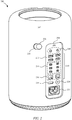
- FIG. 2 shows another embodiment of compact computing system 100 in the form of compact computing system 200.
- compact computing system 200 can be substantially the same or similar as compact computing system 100 with respect to size and shape of housing 102.
- Compact computing system 200 can include housing 202 that can differ from housing 102.
- housing 202 can include opening 204 having a size and shape in accordance with interface panel 206.
- Interface panel 206 can include various ports used for communication of data between compact computing system 200 and various external circuits.
- interface panel 206 can include audio jack ports 208 that can be used to provide an audio stream to an external audio circuit, such as a headphone circuit, audio processor, and the like.
- a set of data ports 210 can be used to transfer data of various forms and/or power between an external circuit(s) and compact computing system 200.
- Data ports 210 can be used to accommodate data connections such as USB, Thunderbolt®, and so on.
- the set of data ports 210 can include data ports 212 in the form of USB ports whereas data ports 214 can take the form of Thunderbolt® ports.
- compact computing system 200 can be interconnected to other computing systems such as data storage devices, portable media players, and video equipment, as well as to form a network of computing systems.
- data ports 216 can take the form of Ethernet ports suitable for forming communication channels to other computing systems and external circuits whereas data port 218 in the form of an HDMI port can be used for audio/video (AV) data transport.
- AV audio/video
- data port 218 can be used to stream high speed video between compact computing system 200 and an external video monitor or other video processing circuitry.
- interface panel 206 can be used to form connections to a large number and variety of external computing systems and circuits which is particularly useful in those situations where a large amount of computing resources are required without the high capital costs associated with large mainframe type computers.
- the compact size and shape of compact computing system 200 also lends itself to space efficient computing networks, data farms, and the like.
- Interface panel 206 can be made of a non-conductive material to electrically insulate each of the ports from one another and from housing 202. Accordingly, interface panel 206 may include a plastic inlay dyed to provide a cosmetic appeal to computing system 200. For example, in some embodiments interface panel 206 is dyed with a black or dark tint. Below the surface of interface panel 206, a conductive web supported by a conductive gasket maintains a Faraday cage for RF and EMI insulation formed between housing 202 and upper and lower conductive gaskets (118, 120) located at an interior surface of housing 202.
- Power on/off button 220 can be readily available to accept a user touch for initiating a power on sequence (including, for example, boot up process) as well as a power down sequence.
- Power input port 222 can be sized and shaped to accept a power plug suitable for transferring external power to operational components within housing 202.
- compact computing system 200 can include internal power resources (such as a battery) that can be charged and re-charged in accordance with power delivered by way of power input port 222.
- Housing interlock opening 224 can be accommodate housing interlock 226 used to secure housing 202 to internal structures of compact computing system 200.
- Housing interlock 226 can take the form of a sliding latch or other such mechanism that can be manually engaged and disengaged. In this way, housing 202 can be easily removed in order to expose internal components and structures for servicing, for example.
- a detection circuit can be used to detect if housing 202 is properly in place with respect to internal components and structures. This is particularly important since thermal management of compact computing system 200 relies to a large degree on the presence and proper placement of housing 202.
- the detection circuit will prevent compact computing system 200 from operating, or at least operating at full capacity.
- the detection circuit can include a magnetic sensor (such as a Hall Effect device) located to detect a magnet(s) disposed on housing 202 only when housing 202 is properly placed and aligned.
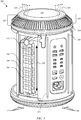
- Removing housing 202 can expose a central core of compact computing system 200. More specifically, FIG. 3 shows central core 300 of compact computing system 200 absent housing 202.
- Central core 300 can include a computing engine having computational components and a heat sink that can be used as a framework used to support at least some of the computational components. In this way, the computing engine takes on a form factor in accordance with that of the heat sink. Accordingly, the cylindrical shape of compact computing system 200 dictates the arrangement of various internal components as well as requirements for thermal management. For example, internal components can be arranged in an axial manner that optimizes both a component packing density (the number of operational components per available volume) and a computing power density (computing power per available volume).
- the axial arrangement of internal components also optimizes an amount of heat that can be transferred to intake airflow 124 from the internal components and removed by way of exhaust airflow 114. (It should be noted that, in general, the nature of compact computing system 200 provides that intake airflow 124 be about the same as that of exhaust air flow 114.)
- memory module 302 can be formed of substrate 304 on which is mounted memory device 306.
- Substrate 304 can have major axis 310 that is parallel to peripheral airflow 312.
- memory device 306 can be mounted onto substrate 304 in a manner that maximizes a thermal transfer interface with peripheral airflow 312.
- each memory device can have a shape corresponding to a minor dimension (representing a width W, for example) and a major dimension (represented by a length L , for example).
- the minor dimension W of memory device 306 is aligned generally parallel to peripheral airflow 312.
- peripheral airflow 312 is constrained by the presence of housing 202 to flow in a peripheral region defined by an interior surface of housing 202 and central core 300.
- peripheral airflow 312 can be characterized as having substantially no radial components thereby further enhancing the heat transfer capability of peripheral airflow 312 with respect to memory module 302 and memory device 306.
- the axial components of peripheral airflow 312 align with the minor dimension W of memory device 306.
- intake airflow 124 is split into peripheral airflow 312 and central airflow 314 (not shown) that flows within a central portion of the central core 300. Accordingly, peripheral airflow 312 and central airflow 314 are combined forming exhaust airflow 114 prior to passing out of compact computing system 200 through second opening 108.
- air mover 320 can be disposed in proximity to second opening 106 (cf. FIG. 1 ). It should be noted that air mover 320 can combine the central airflow 314 and peripheral airflow 312 back into exhaust airflow 114. Air mover 320 could include air exhaust assembly 322 that can be used to direct exhaust airflow 114 through second opening 106 at least some of which engages with exhaust lip 108 in a manner that facilitates the transfer of thermal energy generated by internal components of compact computing system 200. Air exhaust assembly 322 includes vents 324 to allow exhaust airflow 114 to pass through. Cosmetic shield 326 can be used to cover operational components such as RF circuits and antenna. In this regard, cosmetic shield 326 can be formed of RF transparent material such as plastic, ceramic, or other non-conductive materials.
- housing 202 can be used as a chassis ground to provide a good ground for internal components. Accordingly, touch points 328 can be formed of conductive material and be used to form a conductive path between internal components and an interior of housing 202. It should be noted that in order to make a good electrical connection, portions of housing 202 contacting touch points 328 are devoid of any non-conductive or insulating material (such as aluminum oxide). Therefore, in those cases where housing 202 has an aluminum oxide layer formed thereon, selected portions of the aluminum oxide are removed (or that portion of housing 102 masked during the anodization operation) to expose bulk material in those locations that come into contact with touch points 328. As discussed above, in order to prevent leakage of electromagnetic energy, housing 202 and base unit 116 forms a Faraday cage.
- central core 300 may include sensors such as accelerometers disposed on a plurality of points.
- sensors such as accelerometers disposed on a plurality of points.
- illumination patterns can be used to highlight aspects of interface panel 206 so as to make portions of interface panel 206 more visible to the user.
- some of the sensors may include light sensing devices to determine whether or not there is sufficient ambient illumination for the user to see selected items on interface panel 206.
- FIG. 4A shows an exploded view 400 of compact computing system 200 including housing 202 and central core 300.
- Central core 300 includes air mover 320, computing engine 402, and base unit 116.
- Central core 300 may also include a Power Supply Unit (PSU) 404 coupled to interface panel 206 on the outside surface (facing the user).
- PSU Power Supply Unit
- Computing engine 402 includes heat sink 406 for heat exchange with central air flow 314.
- Heat sink 406 may also include a plurality of vertical members (or 'stanchions') 408 along the vertex of the polygonal cross section.
- Vertical members 408 may include attachment features so that a fastener (e.g., through holes for a screw) may attach base unit 116 and air mover 320 to computing engine 402 to form central core 300.
- heat sink 406 includes planar faces 407 that define a central thermal zone having a triangular cross section.
- Heat sink 406 also includes at least one cooling fin 409 that extends longitudinally at least part of a length of a corresponding planar face and spans the central thermal zone.
- a center cooling fin extends from a first planar face to a junction of a second planar face and a third planar face and bisects the central thermal zone into a first region and a second region each having similar triangular cross sections.
- a first cooling fin different from the central cooling fin extends from the first planar face to the second planar face and spans the first region whereas a second cooling fin different from the first cooling fin and the central cooling fin extends from the first planar face to the third planar face and spans the second region.
- a first angle between the first cooling fin and the first planar face varies in accordance with a distance between the first cooling fin and the center cooling fin and a second angle between the second cooling fin and the first planar face varies in accordance with a distance between the second cooling fin and the center cooling fin such that a summation of the first angle and the second angle is equal to about 180°.
- computing engine 402 includes main logic board (MLB) 410.
- MLB 410 may be formed in a circular printed circuit board (PCB), on a plane substantially orthogonal to the longitudinal axis of housing 202.
- Computing engine 402 may have a polygonal cross-section (such as a triangle described above) such that the polygon is inscribed in the circular cross-section of housing 202.
- computing engine 402 may have a triangular cross section wherein a base of the triangle corresponds with a diameter of the circular cross-section of housing 202 whereas the other two sides of the triangle each form a cord of the circular cross-section of housing 202.
- Air mover 320 may include surface 412 for electrically coupling to upper conductive gasket 120.
- Surface 412 can be laser etched to provide a good fit with upper conductive gasket 120 providing a good seal.
- RF antennas in the top portion of air mover 320 (enclosed by cosmetic shield 326) are electrically insulated from RF and EMI signals through the bottom side of air mover 320.
- Air mover 320 may include an indentation 416 for receiving the top edge of an interface structural wall 418. Air mover 320 also includes a plurality of attachment features 420 for attaching air mover 320 to computing engine 402 (e.g., holes). Interface structural wall 418 supports interface panel 206 (cf. FIG. 2 ). In order to insulate central core 300 from RF-radiation and EMI, interface structural wall 418 may include a layer of a conductive material, such as aluminum. In that regard, the layer of conductive material in interface structural wall 418 may have a thickness that provides adequate RF and EMI insulation. In some embodiments, structural wall 418 may include an aluminum layer that is no less than 10 ⁇ m thick.
- the thickness of the aluminum layer in interface structural wall 418 may be about 100 ⁇ m, or more.
- Structural wall 418 includes a housing latch lead-in feature 422 and a housing latch locking feature 424.
- Base unit 116 includes ribs 426, and an indentation 428 for receiving the bottom edge of interface structural wall 418. Indentation 428 may be a grooved portion along a top perimeter of base unit 116.
- Housing 202 can slide down over central core 300 and stops at base unit 116, completing assembly of compact computing system 200.
- lower conductive gasket 118 couples housing 202 to base unit 116.
- lower conductive gasket 118 can have an outer diameter slightly greater than the inner diameter of housing 202.
- Housing 202 is an integral part of the thermal management operation of compact computing system 200 by forming in effect a chimney for peripheral airflow 312 (cf. FIG. 3 ).
- housing 202 also provides RF and EMI insulation to electronic components and circuitry in central core 300.
- some embodiments of compact computing system 200 are fully operational once housing 202 is in place.
- some embodiments may include sensors mounted on central core 300. The sensors may be configured to enable the operation of compact computing system 200 only once housing 202 is secured in place.
- the sensor may include a Hall effect sensor, the magnet placed in an interior face of housing 202. Thus, when housing 202 is in place, the sensor is engaged and compact computing system 200 is enabled.
- housing 202 provides a cosmetic profile to compact computing system 200 that makes it appealing for users, thus enhancing the marketability of the device.
- housing 202 may also serve as a handle for compact computing system 200, through exhaust lip 108 and the gap formed between air mover 320 and portion 110.
- housing 202 allows a user to carry compact computing system 200 from one place to another.
- the round, omnidirectional format of housing 202 also allows the user to rotate compact computing system 200 in order to have interface panel 206 face a desired direction.
- FIG. 4B shows a partial view of an internal portion of housing 202, according to some embodiments.
- the interior surface of housing 202 includes an anodized aluminum layer such that the outside surface of housing 202 is electrically insulated from circuitry inside central core 300. This enables the function of housing 202 as a Faraday cage for RF and EMI insulation of circuitry in central core 300.
- a ground may be coupled between the outside surface of housing 202 and central core 300.
- Conductive stripes 430 may be laser etched on the anodized interior face of housing 202. Thus, stripes 430 reveal a bulk portion of the conductive layer forming housing 202.
- Conductive stripes 430 electrically couple touch points 328 to the conductive layer in housing 202, aiding in the formation of a Faraday cage providing RF and EMI insulation to circuitry in central core 300.
- FIG. 4B also illustrates bottom laser etched surface 432.
- Latch 434 is actuated by the user to fit into latch locking feature 436 so that latch 434 meets locking feature 436.
- a Hall effect sensor identifies that housing 202 is in a locked position and enables the circuitry to be powered 'on'.
- an I/O illumination feature can activate (e.g., light up with illumination) even if housing 202 is not in a locked configuration.
- sensors such as an accelerometer
- I/O illumination circuitry can be active and operable regardless of whether housing 202 is in a locked configuration.
- compact computing system 200 can be prevented from operating, or at least operating at full capacity, when housing 202 is not locked with respect to base 116.
- FIG. 4C shows a cross sectional view 450 of housing 202 along line A-A of FIG. 4A for compact computing system 200.
- Portion 110, opening 106, exhaust lip 108, upper conductive gasket 120, opening 104, and heat sink 406 have been discussed in detail above.
- top portion 110 has a thickness t 1 that is greater than thickness t 2 of a portion 112 of housing 202.
- a thicker top portion 110 reduces the thermal impact on housing 202 by airflow 114 as it engages portion 110 by way of exhaust lip 108.
- housing 202 made of a thermally conductive material such as a metal (e.g., aluminum)
- a thicker layer of material increases the heat flow out of portion 110.
- FIG. 4C shows an illustrative example where thickness t gradually decreases from a maximum value t 1 at exhaust lip 108 down to a reduced value t 2 in portion 112.
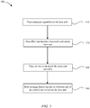
- FIG. 5 shows a flowchart detailing a method 500 for assembling a compact computing system inside a housing, in accordance with the described embodiments.
- the compact computer may include a central core having a processor assembly, a base unit, and an air mover (central core 300, computing engine 402, base unit 116, and air mover 320, cf. FIGS. 3 and 4A ).
- a compact computing system in method 500 may include a PSU and an interface structural wall holding an interface panel (e.g., PSU 404, interface structural wall 418, and interface panel 206).
- Step 510 includes placing the processor assembly on the base unit.
- Step 510 may include attaching fasteners to fixedly couple the processor assembly to the base unit.
- some embodiments may include attaching screws onto bosses placed on the base unit. The screws may pass through holes formed in the processor assembly, thus fixedly coupling the processor assembly to the base unit.
- step 510 may include passing a screw through a slot hole in a vertical member of the processor assembly (e.g., vertical member 408).
- Step 520 includes placing the PSU and the interface structural wall on the base unit.
- the base unit may include a grooved portion along a top perimeter so that a lower edge of the interface structural wall fits in.
- Step 520 may include attaching fasteners to fixedly couple the PSU and the interface panel on the base unit. Accordingly, some embodiments may include using screws as fasteners.
- Step 530 includes placing the air mover on top of the processor assembly.
- step 530 may include attaching fasteners to fixedly couple the air mover to the processor assembly.
- step 530 may include passing a screw through a slot hole in a vertical member of the processor assembly.
- Step 540 includes sliding the housing from the topside to the bottom side of the central core to rest on the base unit.
- the sliding down in step 540 takes place smoothly because a gasket placed on a top interior portion of the housing (e.g., upper conductive gasket 122, cf. FIG. 1 ) contacts the upper edge of the central core when the housing travel is completed.
- the sliding down in step 540 may include using the vertical members in the processor assembly as guiding lines.
- Step 540 provides a concentric configuration between the housing and different components in the central core.
- step 540 may include slightly rotating the housing around the central core. The rotation allows finding a guiding lead for a latch guide so that a latch in the housing may engage a locking feature in the central core.
- a compact computing system can be assembled using a bottom up type assembly.
- Initial assembly operations can include installing a vapor chamber on each side of a triangular central core structure.
- the vapor chamber can take on the form of a two phase (vapor/solid) heat spreader.
- the core can take the form of an aluminum frame secured to and cradled within a fixture.
- High power components such as a graphic processor unit (GPU) and/or central processor unit (CPU) can be mounted directly to the vapor chambers.
- GPU graphic processor unit
- CPU central processor unit
- a good thermal contact can be formed between the vapor chambers and the high power components using a thermally conductive adhesive, paste, or other suitable mechanism.
- a main logic board (MLB) can be pressed against a CPU edge connector followed by installation of a GPU flex(es). Once the MLB is seated and connected to the CPU and GPU, memory modules can be installed after which an inlet assembly can be installed and coupled to the core structure using fasteners.
- An input/output (I/O) assembly that has been independently assembled and pre-tested can be installed after which a power supply unit (PSU) flex can be connected to the MLB followed by connecting the DC PSU power using a bus bar system.
- An exhaust assembly can be installed followed by connecting a RF antenna flex to an I/O assembly.
- Final assembly can include locking the assembly from top down
- FIG. 6A shows a multi-computing system arrangement 600 in accordance with the described embodiments.
- Arrangement 600 can include compact computing systems 602 in a stacked arrangement in rack 604.
- each of the compact computing systems can be interconnected with each other to form a network, for example, compact computing systems 602 can be oriented in any number of directions.
- compact computing systems 602 are arranged horizontally such that air intake/exhaust do not interfere with each other.
- cooling air can be pulled in on one side of rack arrangement 604 and exhausted on another side. In this way exhaust air from one compact computing system is not likely to be re-circulated into an intake of a nearby computing system.
- Compact computing systems 602 can be arranged in such a manner can also be in direct communication via data connectors 606.
- Data connectors 606 can be embodied by Ethernet cables, Thunderbolt® cables, or any number of other high speed data transfer protocol.
- the depicted compact computing systems can be in wireless communication.
- FIG. 6B shows a configuration in which a number of compact computing system are slaved to master compact computing system, thereby allowing the master compact computing system 610 to allocate resources of the various other compact computing systems.
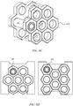
- FIG. 6C shows various other arrangements compatible with the described compact computing systems.
- "honey comb" rack 620 can be used to arrange compact computing systems 602 in a highly efficient close packed arrangement illustrated in various cross sections in FIG. 6D .
- a perspective view and cross sectional view of one embodiment are depicted showing a hexagonal arrangement of compact computing systems.
- the compact computing systems can be arranged in a linear arrangement.
- FIG. 7 is a flowchart detailing a process in accordance with the described embodiments.
- Process 700 is carried out by detecting the movement of the desktop computing system by a sensor at 702 and at 704 providing a movement detection signal by the sensor to a processor in accordance with the movement and altering an operation of the desktop computing system in accordance with the movement at 706.
- FIG. 8 is a block diagram of a computing system 800 suitable for use with the described embodiments.
- the computing system 800 illustrates circuitry of a representative computing system.
- the computing system 800 includes input device 801 coupled to a processor 802 that pertains to a microprocessor or controller for controlling the overall operation of the computing system 800.
- the computing system 800 stores data (such as media data) in a file system 804 and a cache 806.
- the file system 804 typically provides high capacity storage capability for the computing system 800.
- the cache 806 is, for example, Random-Access Memory (RAM) provided by semiconductor memory.
- the computing system 800 can also include a RAM 808 and a Read-Only Memory (ROM) 810.
- the ROM 810 can store programs, utilities or processes to be executed in a non-volatile manner.
- the computing system 800 also includes a network/bus interface 814 that couples to a data link 812.
- the data link 812 allows the computing system 800 to couple to a host computer or to accessory devices.
- the data link 812 can be provided over a wired connection or a wireless connection.
- the network/bus interface 814 can include a wireless transceiver.
- the media items (media data) can pertain to one or more different types of media content.
- the media items are audio tracks (e.g., songs, audio books, and podcasts).
- the media items are images (e.g., photos).
- the media items can be any combination of audio, graphical or visual content.
- Sensor 816 can take the form of circuitry for detecting any number of stimuli.
- sensor 816 can include a Hall Effect sensor responsive to external magnetic field, an audio sensor, a light sensor such as a photometer, and so on.
Landscapes
- Engineering & Computer Science (AREA)
- Theoretical Computer Science (AREA)
- Physics & Mathematics (AREA)
- Human Computer Interaction (AREA)
- General Engineering & Computer Science (AREA)
- General Physics & Mathematics (AREA)
- Computer Hardware Design (AREA)
- Power Engineering (AREA)
- Electromagnetism (AREA)
- Casings For Electric Apparatus (AREA)
- Cooling Or The Like Of Electrical Apparatus (AREA)
- Shielding Devices Or Components To Electric Or Magnetic Fields (AREA)
Description
- The embodiments described herein relate generally to compact computing systems. More particularly, the present embodiments relate to organization of structures and components and fabrication of enclosures suitable for compact computing systems such as a desktop computer.
- The outward appearance of a compact computing system, including its design and its heft, is important to a user of the compact computing system, as the outward appearance contributes to the overall impression that the user has of the compact computing system. At the same time, the assembly of the compact computing system is also important to the user, as a durable assembly will help extend the overall life of the compact computing system and will increase its value to the user.
- One design challenge associated with the manufacture of compact computing systems is the design of the outer enclosures used to house the various internal components. This design challenge generally arises from a number of conflicting design goals that include the desirability of making the outer enclosure or housing lighter, thinner, stronger, and aesthetically pleasing. Lighter housings or enclosures tend to be more flexible and therefore have a greater propensity to buckle and bow, while stronger and more rigid enclosures tend to be thicker and carry more weight. Unfortunately, the increased weight of thicker enclosures may lead to user dissatisfaction with respect to the overall appearance in that they may appear heavy and ill suited for placement on a desktop or in a server rack. However, thinner enclosures can be prone to bowing that may damage internal parts or lead to other failures. Furthermore, the overall appearance of the compact computing system must be aesthetically pleasing as few consumers desire to own or use a device that is perceived to be ugly or unsightly. Due to such considerations, compact computing system enclosure materials are typically selected to provide sufficient structural rigidity while also meeting weight constraints as well as cooperate with thermal systems to maintain operational components within acceptable thermal limits while maintaining any aesthetic appeal worked into materials that meet these criteria.
- An enclosure for a computing system is known from
US2010/002383A1 andUS2005/0036283A1 . - The present application describes various embodiments regarding systems for providing a lightweight and durable compact computing system. Embodiments described below that do not fall within the scope of the appended independent claim do not form part of the invention.
- According to an aspect of the present invention, there is provided an enclosure for a computer system according to
claim 1. - Further, optional, features are recited in each of the claims 2 to 9.
- Other apparatuses, methods, features and advantages of the invention will be or will become apparent to one with skilled in the art upon examination of the following figures and detailed description.
- The included drawings are for illustrative purposes and serve only to provide examples of possible structures and arrangements for the disclosed inventive apparatuses and methods for providing compact computing systems. These drawings in no way limit any changes in form and detail that may be made to the invention by one skilled in the art without departing from the scope of the invention. The embodiments will be readily understood by the following detailed description in conjunction with the accompanying drawings, wherein like reference numerals designate like structural elements.
-
FIG. 1 shows a perspective view of an embodiment of a compact computing system in a stand alone and upright configuration. -
FIG. 2 shows a perspective view of another embodiment of a compact computing system in accordance with the described embodiments. -
FIG. 3 shows a perspective view of a general system layout of the compact computing system ofFIG. 2 . -
FIG. 4A shows an exploded view of a compact computing system including a housing and a central core, according to some embodiments. -
FIG. 4B shows a partial view of an internal portion of the housing for a compact computing system, according to some embodiments. -
FIG. 4C shows a cross sectional view of a housing for a compact computing system, according to some embodiments. -
FIG. 5 shows a flowchart detailing a method for assembling a compact computing system inside a housing, in accordance with the described embodiments. -
FIG. 6A shows a rack arrangement suitable for supporting a number of the compact computing systems. -
FIGS. 6B-6D shows various other rack arrangements suitable for supporting a number of compact computing systems. -
FIG. 7 is a flowchart detailing a process in accordance with the described embodiments. -
FIG. 8 is a block diagram of a computing system suitable for use with the described embodiments. - In the figures, elements having the same or similar reference numeral have the same or similar function and description.
- Representative applications of apparatuses and methods according to the presently described embodiments are provided in this section. These examples are being provided solely to add context and aid in the understanding of the described embodiments. It will thus be apparent to one skilled in the art that the presently described embodiments can be practiced without some or all of these specific details. In other instances, well known process steps have not been described in detail in order to avoid unnecessarily obscuring the presently described embodiments. Other applications are possible, such that the following examples should not be taken as limiting.
- The following relates to a compact computing system that can be configured as a stand-alone unit for placement upon or under a desk or other work area (also referred to as a desktop computer). The compact computing system can also be configured as part of a group of networked or otherwise interconnected computers. In any case, the compact computing system can include a number of electronic components including at least a central processing unit (CPU), and a graphics processing unit (GPU), and other primary and secondary components such a solid state memory devices, wireless components and so on. One or more internal electronic component boards can be shaped to match a surface of the outer enclosure of the compact computing system, including for example, a circular shape to match a top or bottom of a cylinder, or a curved shape to match a segment of an arc conforming to a curved exterior surface of the outer enclosure. In representative embodiments as described herein, the compact computing system can be cylindrical in shape and can be configured to arrange a number of rectangular electronic components as a central core providing a form factor characterized as having a high component packing density (a number of components per available volume). The resulting compact computing device can provide a high computing power density in a small, lightweight, transportable form factor. In some embodiments, the compact computing device can also be coupled to other compact computing devices to form a multi-computer system that can be used as a server computer system (such as in a data farm) or as a network computing system having each compact computing device as a node (or nodes).
- For example, in the embodiments described herein, the compact computing system can be cylindrical and be configured in such a way that the rectangular electronic components can be assembled as a central core with a form factor having a high component packing density (number of components per available volume). The central core can also have a cylindrical shape in concurrence with a housing having an annular cylindrical shape along the lines of a tube. A thermal management system can utilize an air mover that can be move copious amounts of air axially through an interior volume defined by the housing that can be used to cool a central core of the compact computing system in a manner that is both efficient and quiet. Generally speaking, the air mover can provide a volume of air per unit time in the form of an airflow of about 15 - 20 cubic feet per minute (CFM) when major components such as a central processing unit (CPU) and/or a graphics processing unit (GPU) are not being heavily utilized. However, when processing demand increases, the air mover can compensate for any increase in heat generated by ramping up the airflow. For example, in response to an increase in demand for processing resources from either or both the CPU and/or GPU, the air mover can increase the airflow from about 15 - 20 CFM to about 25 - 30 CFM (at about room temperature of 25°C) with an acoustic output of about 35 dbA (it should be noted that these acoustic levels are only experienced when the air mover is performing at a higher end of its operating range during a period of high demand and not during more normal operation). It should be noted that at higher ambient temperature (35°C), the air mover can ramp the airflow even further to compensate for the reduced thermal transfer at the higher ambient temperature. In this situation, the air mover can ramp the airflow to about 35 to 40 CFM or more having a higher acoustic output of 40 dbA or more.
- The air mover can occupy a substantial amount of available cross sectional real estate defined by the housing providing an axial airflow substantially free of radial airflow components. Moreover, components that make up the central core can be aligned in an axial manner that maximizes an amount of surface area in thermal contact with the axial airflow. Furthermore, the design and layout of the components can also be axial in nature further enhancing the available heat transfer capability and component packing density that leads to higher computing power density (computing operations per available volume). For example, an integrated circuit can be designed to have a power input node (s) at a first end of the integrated circuit and data I/Os at an opposite end of the integrated circuit.
- The compact computing system can also be coupled to other compact computing systems to form a multi-computer system that can be used as a server computer system (such as in a data farm) or as a network computing system having each compact computing system as a node (or nodes). One advantage of the compact size and shape of the compact computing system is that a simple racking system (along the lines of a wine rack configuration) can be used to position the multiple connected compact computing systems. For example, the individual compact computing systems can be placed at an angle within a rack arrangement in such a way as to provide easy access to inputs as well as outputs for connection to other devices without restricting the flow of air into or out of the compact computing system. In some cases, the individual compact computing systems can be stacked in an alternating arrangement that also does not restrict either air intake or air exhaust. These and other general subjects are set forth in greater detail below.
- In a particular embodiment, the compact computing system can include a housing that can surround and protect the central core. The housing can be easily removed for servicing or other access. The housing can be formed of aluminum having an aluminum oxide (alumina) layer that both protects the housing and promotes radiative cooling. The aluminum oxide/anodization layer also improved heat rejection from external surface of the housing by increasing its infrared radiative emissivity. Aluminum has a number of characteristics that make it a good choice for the housing. For example, aluminum is a good electrical conductor that can provide good electrical ground and it can be easily machined and has well known metallurgical characteristics. The superior conductivity of aluminum provides a good chassis ground for internal electrical components arranged to fit and operate within the housing. The aluminum housing also provides a good electromagnetic interference (EMI) shield protecting sensitive electronic components from external electromagnetic energy as well as reducing leakage of electromagnetic (EM) energy from the compact computing system. A layer of aluminum oxide can be formed on the surface of the aluminum in a process referred to as anodization. In some cases, the layer of aluminum oxide can be dyed or otherwise imbued with a color(s) to take on a specific color or colors. It should be noted that since aluminum oxide is a good electrical insulator, either the interior surface of the housing is masked during the anodization process to preserve access to the bulk material or selected portions of the layer of aluminum oxide are removed to provide good electrical contacts.
- In one embodiment, the cylindrical housing can take the form of a single piece housing (monolithic). In this way, the cylindrical housing appears seamless and homogenous. The cylindrical shape of the housing maximizes the ratio of internal volume and enclosure volume. In one embodiment, the housing is formed of a single billet of a strong and resilient material such as aluminum that is surface treated (anodized) to provide an aesthetically pleasing appearance. A top portion of the cylindrical housing is formed into the lip used to engage a circumferential portion of the airflow that travels in an axial direction from the first opening to the second opening at which point the airflow passes to an external environment. The lip can also be used to transport the compact computing system using for example, a hand.
- In a particular embodiment, a compact computing system can be assembled using a bottom up type assembly. Initial assembly operations can include installing a vapor chamber on each side of a triangular central core structure. In the described embodiments, the vapor chamber can take on the form of a two phase (vapor/solid) heat spreader. In a particular implementation, the core can take the form of an aluminum frame secured to and cradled within a fixture. High power components, such as a graphic processor unit (GPU) and/or central processor unit (CPU) can be mounted directly to the vapor chambers.
- A good thermal contact can be formed between the vapor chambers and the high power components using a thermally conductive adhesive, paste, or other suitable mechanism. A main logic board (MLB) can be pressed against a CPU edge connector followed by installation of a GPU flex(es). Once the MLB is seated and connected to the CPU and GPU, memory modules can be installed after which an inlet assembly can be installed and coupled to the core structure using fasteners. An input/output (I/O) assembly that has been independently assembled and pre-tested can be installed after which a power supply unit (PSU) control cable can be connected to the MLB followed by connecting the DC PSU power using a bus bar system. An exhaust assembly can be installed followed by connecting a RF antenna flex to an I/O board.
- The housing takes on a cylindrical shape that encloses and defines a cylindrical volume. In the described embodiment, the housing and the corresponding cylindrical volume can be defined in terms of a right circular cylinder having a longitudinal axis that can be used to define a height of the right circular cylinder. The housing also can be characterized as having a circular cross section having a center point on the longitudinal axis. The circular cross section can have a radius that extends from the center point and is perpendicular to the longitudinal axis. In one embodiment, a thickness of the housing can be defined in terms of a relationship between an inner radius (extending from the center point to an interior surface of the housing) and an outer radius (extending from the center point to an exterior surface of the housing).
- The housing can have a thickness tuned to promote circumferential and axial conduction that aids in the spreading out of heat in the housing thereby inhibiting formation of hot spots. The separation between the central core and the housing allows an internal peripheral airflow to cool the housing helping to minimize a touch temperature of the housing. In one embodiment, the housing can be mated to a base unit that provides, in part, a pedestal used to support the compact computing system on a surface. In one embodiment, the base unit can be a removable base unit. The housing can include a first opening having a size and shape in accordance with the base unit. The first opening can be a full perimeter air inlet whose circular design allows for functionality even in those situations where the compact computing system is located in a corner or against a wall. In an assembled configuration, the base unit corresponds to a base of the cylinder. The first opening can be used to accept a flow of air from an external environment passing through vents in the base unit. The amount of air that flows into the housing is related to a pressure differential between the external environment and an interior of the compact computing system created by an air mover assembly near a second opening axially disposed from the first opening. A thermal management system can utilize the air mover that can be move copious amounts of air axially through an interior volume defined by the cylindrical housing that can be used to cool the central core in a manner that is both efficient and quiet.
- In one embodiment, an air exhaust assembly can take the form of a fan assembly. The fan assembly can be an axial fan assembly configured to axially move air through the housing by creating the abovementioned pressure differential. The fan assembly can also be configured as a mixed air fan assembly providing both axial and centrifugal components to air as it exits the fan assembly. In one embodiment, the fan assembly can occupy a substantial portion of available cross sectional area of the cylindrical housing. For example, the fan assembly can account for at least 85% or thereabouts of an available cross sectional area of an interior of the housing. In any case, air can enter through the vents in the base unit. In one embodiment, a baffle arrangement can bifurcate (split) the airflow in such a way that some of the airflow remains within a central column separate from a peripheral airflow located away from the central column. The central column of air can thermally engage a heat sink structure on which internal components can be mounted. In order to optimize thermal transfer, components can be configured and mounted axially (in the direction of air flow) in order to maximize an amount of air engaging the components. In this way, both the central airflow and the peripheral airflow can be used to cool the central core and still maintain the housing at an acceptable temperature.
- The housing can include an exhaust lip at the second opening. The exhaust lip can be arranged to engage a portion of the air as it flows out of the second opening having the effect of directing the airflow (and sound) away from the user. The exhaust lip can also provide an integrated handle structure suitable for grasping the compact computing system. The housing can have a thickness that is tuned by which it is meant that the housing has a varying thickness in which a portion of the housing nearest the exhaust lip is thicker than that portion away from the exhaust lip. The thickness of the housing can be varied in a manner that promotes an axial and circumferential conduction of heat in the housing that promotes a more even distribution of heat that inhibits the formation of hot spots in the housing.
- A good electrical ground (also referred to as a chassis ground) can be used to isolate components that emit significant electromagnetic energy (such as a main logic board, or MLB) from those circuits, such as wireless circuits, that are sensitive to electromagnetic energy. This isolation can be particularly important in the compact computing system due to the close proximity of components that emit electromagnetic energy and those components that are sensitive to electromagnetic energy. Moreover, the housing can include conductive material (such as a gasket infused with conductive particles) that can be mated to a corresponding attachment feature on the base unit completing the formation of a Faraday cage. The Faraday cage can block electromagnetic energy (both internal and external) effectively shielding the external environment from EMI generated by the compact computing system (and the internal environment from externally generated EMI). In order to complete the Faraday cage, air vents in the base unit can be sized to effectively block electromagnetic energy having selected wavelength. More specifically, the wavelength of electromagnetic energy blocked by the vents can be consistent with that emitted by active components with the compact computing system.
- In one embodiment, the compact computing system can include a sensor configured to detect whether or not the housing is properly in place and aligned with respect to the internal components. Proper placement of the housing is important due to the key role that both the shape and configuration of the housing has with respect to thermal management of the compact computing system as well as completing the Faraday cage discussed above. The compact computing system can include an interlock system that detects the presence and proper alignment of the housing with respect to the internal components. Only when the proper alignment is detected, the interlock system will allow the internal components to power up and operate in a manner consistent with system specification. In one embodiment, the interlock system can include a magnetic element detectable by a Hall effect sensor only when the housing is in a proper position and alignment with respect to the internal components.
- Due at least to the strong and resilient nature of the material used to form the housing; the housing can include a large opening having a span that does not require additional support structures. Such an opening can be used to provide access to an input/output panel and power supply port. The input/output panel can include, for example, data ports suitable for accommodating data cables configured for connecting external circuits. The opening can also provide access to an audio circuit, video display circuit, power input, etc. In one embodiment, selected data ports can be illuminated to provide easier access in reduced lighting.
- These and other embodiments are discussed below with reference to
FIGs. 1 - 8 . However, those skilled in the art will readily appreciate that the detailed description given herein with respect to these figures is for explanatory purposes as the invention extends beyond these limited embodiments. -
FIG. 1 shows a perspective view ofcompact computing system 100.Compact computing system 100 can have a shape defined byhousing 102. In the described embodiments,housing 102 can be cylindrical in shape having afirst opening 104 characterized as having diameter d1. More specifically,housing 102 can take the form of a circular right cylinder having a longitudinal axis that extends long a centerline of a central volume enclosed byhousing 102. Housing 102 can be characterized as having a circular cross section having a center point coincident with a corresponding point on the longitudinal axis. The circular cross section has a radius that is perpendicular to the longitudinal axis and extends outwardly therefrom. Accordingly, thickness t of housing 102 (more specifically a housing wall) can be defined as a difference between an outer radius ro associated with an exterior ofhousing 102 and inner radius ri associated with an interior surface ofhousing 102. Moreover,housing 102 can includesecond opening 106 axially disposed fromfirst opening 104 having diameter d2 defined in part byexhaust lip 108 where d1 is at least equal to or greater than d2. Housing 102 can be formed from a single billet of aluminum in the form of a disk that can be extruded in a manner formingexhaust lip 108. Thickness t ofhousing 102 can be tuned to mitigate hot spots. In this regard, housing102 can have a non-uniform thickness t. In particular,portion 110near exhaust lip 108 can have a first thickness of about 4 - 6 mm that then changes to a second thickness associated withportion 112 that is reduced from the first thickness and located away fromexhaust lip 108. In this way,portion 110 can act as both an integrated handle used to graspcompact computing system 100 and as a feature that absorbs and conducts thermal energy transferred from a portion ofexhaust airflow 114 that engagesexhaust lip 108. Through radiative and conductive heat transfer and by limiting the amount of heat transferred toportion 112, the formation of local hot spots inhousing 102 can be mitigated. Tuning the thickness ofhousing 102 can be accomplished using, for example, an impact extrusion process using a metal disk that is then machined to the desired thickness profile. The metal disk may be made of aluminum, titanium, and any other metallic material that provides the strength, thermal conductivity, and RF-isolation desired. The extrusion process forms a cylinder that is machined in the exterior portion and in the interior portion to acquire the desired cross sectional profile and also the desired visual appeal from the exterior. -
Compact computing system 100 can further includebase unit 116.Base unit 116 can be used to provide support forcompact computing system 100. Accordingly,base unit 116 can be formed of strong and resilient material along the lines of metal that can also prevent leakage of electromagnetic (EM) energy from components withincompact computing system 100 that radiate EM energy during operation.Base unit 116 can also be formed of non-metallic compounds that can nonetheless be rendered electrically conductive using, for example, electrically conductive particles embedded therein. In order to assure that any electromagnetic energy emitted by components withincompact computing system 100 does not leak out, lowerconductive gasket 118 can be used to complete a Faraday cage formed bybase unit 116 andhousing 102. Upper conductive gasket 120 (shown in more detail inFIG. 3 ) can be disposed on the interior surface ofhousing 102 near a lower edge ofportion 110. Use ofconductive gaskets -
Base unit 116 can also include vents 122.Vents 122 can be dual purpose in that vents 122 can be arranged inbase unit 116 in such a way that a suitable amount of air from an external environment can flow throughvents 122 in the form ofintake airflow 124. In one embodiment,intake airflow 124 can be related to a pressure differential acrossvents 122 created by an air mover disposed withcompact computing system 100. In one embodiment, the air mover can be disposed nearsecond opening 106 creating a suction effect that reduces an ambient pressure withinhousing 102. In addition to facilitatingintake airflow 124,vents 122 can be sized to prevent leakage of electromagnetic energy there through. The size ofvents 122 can be related to a wavelength corresponding to electromagnetic energy emitted by internal components. -
FIG. 2 shows another embodiment ofcompact computing system 100 in the form ofcompact computing system 200. It should be noted thatcompact computing system 200 can be substantially the same or similar ascompact computing system 100 with respect to size and shape ofhousing 102.Compact computing system 200 can includehousing 202 that can differ fromhousing 102. In this embodiment,housing 202 can include opening 204 having a size and shape in accordance withinterface panel 206.Interface panel 206 can include various ports used for communication of data betweencompact computing system 200 and various external circuits. For example,interface panel 206 can includeaudio jack ports 208 that can be used to provide an audio stream to an external audio circuit, such as a headphone circuit, audio processor, and the like. A set ofdata ports 210 can be used to transfer data of various forms and/or power between an external circuit(s) andcompact computing system 200.Data ports 210 can be used to accommodate data connections such as USB, Thunderbolt®, and so on. For example, the set ofdata ports 210 can includedata ports 212 in the form of USB ports whereasdata ports 214 can take the form of Thunderbolt® ports. In this way,compact computing system 200 can be interconnected to other computing systems such as data storage devices, portable media players, and video equipment, as well as to form a network of computing systems. Furthermore,data ports 216 can take the form of Ethernet ports suitable for forming communication channels to other computing systems and external circuits whereasdata port 218 in the form of an HDMI port can be used for audio/video (AV) data transport. In this way,data port 218 can be used to stream high speed video betweencompact computing system 200 and an external video monitor or other video processing circuitry. Accordingly,interface panel 206 can be used to form connections to a large number and variety of external computing systems and circuits which is particularly useful in those situations where a large amount of computing resources are required without the high capital costs associated with large mainframe type computers. Moreover, the compact size and shape ofcompact computing system 200 also lends itself to space efficient computing networks, data farms, and the like. -
Interface panel 206 can be made of a non-conductive material to electrically insulate each of the ports from one another and fromhousing 202. Accordingly,interface panel 206 may include a plastic inlay dyed to provide a cosmetic appeal tocomputing system 200. For example, in someembodiments interface panel 206 is dyed with a black or dark tint. Below the surface ofinterface panel 206, a conductive web supported by a conductive gasket maintains a Faraday cage for RF and EMI insulation formed betweenhousing 202 and upper and lower conductive gaskets (118, 120) located at an interior surface ofhousing 202. Power on/offbutton 220 can be readily available to accept a user touch for initiating a power on sequence (including, for example, boot up process) as well as a power down sequence.Power input port 222 can be sized and shaped to accept a power plug suitable for transferring external power to operational components withinhousing 202. In some cases,compact computing system 200 can include internal power resources (such as a battery) that can be charged and re-charged in accordance with power delivered by way ofpower input port 222. - Housing interlock opening 224 can be accommodate
housing interlock 226 used to securehousing 202 to internal structures ofcompact computing system 200.Housing interlock 226 can take the form of a sliding latch or other such mechanism that can be manually engaged and disengaged. In this way,housing 202 can be easily removed in order to expose internal components and structures for servicing, for example. It should be noted that although not shown, a detection circuit can be used to detect ifhousing 202 is properly in place with respect to internal components and structures. This is particularly important since thermal management ofcompact computing system 200 relies to a large degree on the presence and proper placement ofhousing 202. Therefore, it is desired that if it is determined thathousing 202 is not in proper placement or alignment with respect to internal structures or components, then the detection circuit will preventcompact computing system 200 from operating, or at least operating at full capacity. In one embodiment, the detection circuit can include a magnetic sensor (such as a Hall Effect device) located to detect a magnet(s) disposed onhousing 202 only whenhousing 202 is properly placed and aligned. - Removing
housing 202 can expose a central core ofcompact computing system 200. More specifically,FIG. 3 showscentral core 300 ofcompact computing system 200absent housing 202.Central core 300 can include a computing engine having computational components and a heat sink that can be used as a framework used to support at least some of the computational components. In this way, the computing engine takes on a form factor in accordance with that of the heat sink. Accordingly, the cylindrical shape ofcompact computing system 200 dictates the arrangement of various internal components as well as requirements for thermal management. For example, internal components can be arranged in an axial manner that optimizes both a component packing density (the number of operational components per available volume) and a computing power density (computing power per available volume). Moreover, the axial arrangement of internal components also optimizes an amount of heat that can be transferred tointake airflow 124 from the internal components and removed by way ofexhaust airflow 114. (It should be noted that, in general, the nature ofcompact computing system 200 provides thatintake airflow 124 be about the same as that ofexhaust air flow 114.) - For example,
memory module 302 can be formed ofsubstrate 304 on which is mountedmemory device 306.Substrate 304 can havemajor axis 310 that is parallel toperipheral airflow 312. In order to optimize heat transfer frommemory device 306 toperipheral airflow 312,memory device 306 can be mounted ontosubstrate 304 in a manner that maximizes a thermal transfer interface withperipheral airflow 312. For example, each memory device can have a shape corresponding to a minor dimension (representing a width W, for example) and a major dimension (represented by a length L , for example). In the embodiment shown, the minor dimension W ofmemory device 306 is aligned generally parallel toperipheral airflow 312. In this way, a thermal transfer interface formed betweenperipheral airflow 312 andmemory device 306 disposed onmemory module 304 can be optimized. It should also be noted thatperipheral airflow 312 is constrained by the presence ofhousing 202 to flow in a peripheral region defined by an interior surface ofhousing 202 andcentral core 300. Moreover,peripheral airflow 312 can be characterized as having substantially no radial components thereby further enhancing the heat transfer capability ofperipheral airflow 312 with respect tomemory module 302 andmemory device 306. In this way, the axial components ofperipheral airflow 312 align with the minor dimension W ofmemory device 306. It should be noted thatintake airflow 124 is split intoperipheral airflow 312 and central airflow 314 (not shown) that flows within a central portion of thecentral core 300. Accordingly,peripheral airflow 312 andcentral airflow 314 are combined formingexhaust airflow 114 prior to passing out ofcompact computing system 200 throughsecond opening 108. - In the described embodiment,
air mover 320 can be disposed in proximity to second opening 106 (cf.FIG. 1 ). It should be noted thatair mover 320 can combine thecentral airflow 314 andperipheral airflow 312 back intoexhaust airflow 114.Air mover 320 could includeair exhaust assembly 322 that can be used todirect exhaust airflow 114 throughsecond opening 106 at least some of which engages withexhaust lip 108 in a manner that facilitates the transfer of thermal energy generated by internal components ofcompact computing system 200.Air exhaust assembly 322 includesvents 324 to allowexhaust airflow 114 to pass through.Cosmetic shield 326 can be used to cover operational components such as RF circuits and antenna. In this regard,cosmetic shield 326 can be formed of RF transparent material such as plastic, ceramic, or other non-conductive materials. - Due to the electrically conductive nature of
housing 202,housing 202 can be used as a chassis ground to provide a good ground for internal components. Accordingly, touch points 328 can be formed of conductive material and be used to form a conductive path between internal components and an interior ofhousing 202. It should be noted that in order to make a good electrical connection, portions ofhousing 202 contactingtouch points 328 are devoid of any non-conductive or insulating material (such as aluminum oxide). Therefore, in those cases wherehousing 202 has an aluminum oxide layer formed thereon, selected portions of the aluminum oxide are removed (or that portion ofhousing 102 masked during the anodization operation) to expose bulk material in those locations that come into contact with touch points 328. As discussed above, in order to prevent leakage of electromagnetic energy,housing 202 andbase unit 116 forms a Faraday cage. - In order to provide a user-friendly interaction with
compact computing system 200,central core 300 may include sensors such as accelerometers disposed on a plurality of points. Thus, as the user handleshousing 202 in order to positioncompact computing system 200 in a convenient location and orientation, illumination patterns can be used to highlight aspects ofinterface panel 206 so as to make portions ofinterface panel 206 more visible to the user. Accordingly, some of the sensors may include light sensing devices to determine whether or not there is sufficient ambient illumination for the user to see selected items oninterface panel 206. -
FIG. 4A shows an explodedview 400 ofcompact computing system 200 includinghousing 202 andcentral core 300.Central core 300 includesair mover 320,computing engine 402, andbase unit 116.Central core 300 may also include a Power Supply Unit (PSU) 404 coupled tointerface panel 206 on the outside surface (facing the user).Computing engine 402 includesheat sink 406 for heat exchange withcentral air flow 314.Heat sink 406 has a cross section can take the form of an m-sided polygon (of which the rectangle is one in which m = 4 and a triangle where m = 3) where m is an integer having a value of at least 3 (that may or may not be equal to n), the sides of the polygon forming a base for mounting processor boards such as CPU board and GPU boards. In other words, there are many geometric arrangements and relationships that are suitable betweenhousing 100/102 and thecentral core 300.Heat sink 406 may also include a plurality of vertical members (or 'stanchions') 408 along the vertex of the polygonal cross section.Vertical members 408 may include attachment features so that a fastener (e.g., through holes for a screw) may attachbase unit 116 andair mover 320 tocomputing engine 402 to formcentral core 300. - It should be noted that in a specific embodiment,
heat sink 406 includes planar faces 407 that define a central thermal zone having a triangular cross section.Heat sink 406 also includes at least onecooling fin 409 that extends longitudinally at least part of a length of a corresponding planar face and spans the central thermal zone. Moreover, a center cooling fin extends from a first planar face to a junction of a second planar face and a third planar face and bisects the central thermal zone into a first region and a second region each having similar triangular cross sections. Furthermore, a first cooling fin different from the central cooling fin extends from the first planar face to the second planar face and spans the first region whereas a second cooling fin different from the first cooling fin and the central cooling fin extends from the first planar face to the third planar face and spans the second region. In the described embodiment, a first angle between the first cooling fin and the first planar face varies in accordance with a distance between the first cooling fin and the center cooling fin and a second angle between the second cooling fin and the first planar face varies in accordance with a distance between the second cooling fin and the center cooling fin such that a summation of the first angle and the second angle is equal to about 180°. - In some embodiments,
computing engine 402 includes main logic board (MLB) 410. Accordingly,MLB 410 may be formed in a circular printed circuit board (PCB), on a plane substantially orthogonal to the longitudinal axis ofhousing 202.Computing engine 402 may have a polygonal cross-section (such as a triangle described above) such that the polygon is inscribed in the circular cross-section ofhousing 202. For example, as shown inFIG. 4A ,computing engine 402 may have a triangular cross section wherein a base of the triangle corresponds with a diameter of the circular cross-section ofhousing 202 whereas the other two sides of the triangle each form a cord of the circular cross-section ofhousing 202.Air mover 320 may include surface 412 for electrically coupling to upperconductive gasket 120. Surface 412 can be laser etched to provide a good fit with upperconductive gasket 120 providing a good seal. Thus, RF antennas in the top portion of air mover 320 (enclosed by cosmetic shield 326) are electrically insulated from RF and EMI signals through the bottom side ofair mover 320. -
Air mover 320 may include anindentation 416 for receiving the top edge of an interfacestructural wall 418.Air mover 320 also includes a plurality of attachment features 420 for attachingair mover 320 to computing engine 402 (e.g., holes). Interfacestructural wall 418 supports interface panel 206 (cf.FIG. 2 ). In order to insulatecentral core 300 from RF-radiation and EMI, interfacestructural wall 418 may include a layer of a conductive material, such as aluminum. In that regard, the layer of conductive material in interfacestructural wall 418 may have a thickness that provides adequate RF and EMI insulation. In some embodiments,structural wall 418 may include an aluminum layer that is no less than 10 µm thick. For example, the thickness of the aluminum layer in interfacestructural wall 418 may be about 100 µm, or more.Structural wall 418 includes a housing latch lead-infeature 422 and a housinglatch locking feature 424.Base unit 116 includesribs 426, and anindentation 428 for receiving the bottom edge of interfacestructural wall 418.Indentation 428 may be a grooved portion along a top perimeter ofbase unit 116. - Housing 202 can slide down over
central core 300 and stops atbase unit 116, completing assembly ofcompact computing system 200. On the bottom end ofhousing 202, lowerconductive gasket 118 couples housing 202 tobase unit 116. In some embodiments, lowerconductive gasket 118 can have an outer diameter slightly greater than the inner diameter ofhousing 202. Thus, oncehousing 202 is lowered down ontobase unit 116, the weight ofhousing 202 presses onto lowerconductive gasket 118 resulting in a concentric bias tohousing 202 that also secureshousing 202 in position. Once in place,housing 202 causes formation of a peripheral air gap betweenvents 122 and the inside surface ofhousing 202. -
Housing 202 is an integral part of the thermal management operation ofcompact computing system 200 by forming in effect a chimney for peripheral airflow 312 (cf.FIG. 3 ). In some embodiments,housing 202 also provides RF and EMI insulation to electronic components and circuitry incentral core 300. In that regard, some embodiments ofcompact computing system 200 are fully operational oncehousing 202 is in place. Accordingly, some embodiments may include sensors mounted oncentral core 300. The sensors may be configured to enable the operation ofcompact computing system 200 only oncehousing 202 is secured in place. For example, the sensor may include a Hall effect sensor, the magnet placed in an interior face ofhousing 202. Thus, whenhousing 202 is in place, the sensor is engaged andcompact computing system 200 is enabled. Further,housing 202 provides a cosmetic profile tocompact computing system 200 that makes it appealing for users, thus enhancing the marketability of the device. In some embodiments,housing 202 may also serve as a handle forcompact computing system 200, throughexhaust lip 108 and the gap formed betweenair mover 320 andportion 110. In that regard,housing 202 allows a user to carrycompact computing system 200 from one place to another. The round, omnidirectional format ofhousing 202 also allows the user to rotatecompact computing system 200 in order to haveinterface panel 206 face a desired direction. -
FIG. 4B shows a partial view of an internal portion ofhousing 202, according to some embodiments. The interior surface ofhousing 202 includes an anodized aluminum layer such that the outside surface ofhousing 202 is electrically insulated from circuitry insidecentral core 300. This enables the function ofhousing 202 as a Faraday cage for RF and EMI insulation of circuitry incentral core 300. In some embodiments, a ground may be coupled between the outside surface ofhousing 202 andcentral core 300.Conductive stripes 430 may be laser etched on the anodized interior face ofhousing 202. Thus,stripes 430 reveal a bulk portion of the conductivelayer forming housing 202.Conductive stripes 430 electrically couple touch points 328 to the conductive layer inhousing 202, aiding in the formation of a Faraday cage providing RF and EMI insulation to circuitry incentral core 300.FIG. 4B also illustrates bottom laser etchedsurface 432.Latch 434 is actuated by the user to fit intolatch locking feature 436 so thatlatch 434 meets lockingfeature 436. By rotatinghousing 202 aboutcentral core 300, a user may find the proper orientation prior to 'dropping'housing 202 into a 'locked' position. In some embodiments, a Hall effect sensor identifies thathousing 202 is in a locked position and enables the circuitry to be powered 'on'. It should be noted that an I/O illumination feature can activate (e.g., light up with illumination) even ifhousing 202 is not in a locked configuration. In some embodiments, sensors (such as an accelerometer) and I/O illumination circuitry can be active and operable regardless of whetherhousing 202 is in a locked configuration. In one embodiment,compact computing system 200 can be prevented from operating, or at least operating at full capacity, whenhousing 202 is not locked with respect tobase 116. -
FIG. 4C shows a crosssectional view 450 ofhousing 202 along line A-A ofFIG. 4A forcompact computing system 200.Portion 110, opening 106,exhaust lip 108, upperconductive gasket 120, opening 104, andheat sink 406 have been discussed in detail above. Accordingly,top portion 110 has a thickness t1 that is greater than thickness t2 of aportion 112 ofhousing 202. A thickertop portion 110 reduces the thermal impact onhousing 202 byairflow 114 as it engagesportion 110 by way ofexhaust lip 108. Inembodiments having housing 202 made of a thermally conductive material such as a metal (e.g., aluminum), a thicker layer of material increases the heat flow out ofportion 110.FIG. 4C shows an illustrative example where thickness t gradually decreases from a maximum value t1 atexhaust lip 108 down to a reduced value t2 inportion 112. -
FIG. 5 shows a flowchart detailing amethod 500 for assembling a compact computing system inside a housing, in accordance with the described embodiments. The compact computer may include a central core having a processor assembly, a base unit, and an air mover (central core 300,computing engine 402,base unit 116, andair mover 320, cf.FIGS. 3 and4A ). Also, a compact computing system inmethod 500 may include a PSU and an interface structural wall holding an interface panel (e.g.,PSU 404, interfacestructural wall 418, and interface panel 206). - Step 510 includes placing the processor assembly on the base unit. Step 510 may include attaching fasteners to fixedly couple the processor assembly to the base unit. For example, some embodiments may include attaching screws onto bosses placed on the base unit. The screws may pass through holes formed in the processor assembly, thus fixedly coupling the processor assembly to the base unit. In that regard,
step 510 may include passing a screw through a slot hole in a vertical member of the processor assembly (e.g., vertical member 408). - Step 520 includes placing the PSU and the interface structural wall on the base unit. The base unit may include a grooved portion along a top perimeter so that a lower edge of the interface structural wall fits in. Step 520 may include attaching fasteners to fixedly couple the PSU and the interface panel on the base unit. Accordingly, some embodiments may include using screws as fasteners.
- Step 530 includes placing the air mover on top of the processor assembly. As in the previous steps,
step 530 may include attaching fasteners to fixedly couple the air mover to the processor assembly. Thus, step 530 may include passing a screw through a slot hole in a vertical member of the processor assembly. - Step 540 includes sliding the housing from the topside to the bottom side of the central core to rest on the base unit. The sliding down in
step 540 takes place smoothly because a gasket placed on a top interior portion of the housing (e.g., upperconductive gasket 122, cf.FIG. 1 ) contacts the upper edge of the central core when the housing travel is completed. Also, the sliding down instep 540 may include using the vertical members in the processor assembly as guiding lines. Step 540 provides a concentric configuration between the housing and different components in the central core. In some embodiments,step 540 may include slightly rotating the housing around the central core. The rotation allows finding a guiding lead for a latch guide so that a latch in the housing may engage a locking feature in the central core. - In a particular embodiment, a compact computing system can be assembled using a bottom up type assembly. Initial assembly operations can include installing a vapor chamber on each side of a triangular central core structure. In the described embodiments, the vapor chamber can take on the form of a two phase (vapor/solid) heat spreader. In a particular implementation, the core can take the form of an aluminum frame secured to and cradled within a fixture. High power components, such as a graphic processor unit (GPU) and/or central processor unit (CPU) can be mounted directly to the vapor chambers.
- A good thermal contact can be formed between the vapor chambers and the high power components using a thermally conductive adhesive, paste, or other suitable mechanism. A main logic board (MLB) can be pressed against a CPU edge connector followed by installation of a GPU flex(es). Once the MLB is seated and connected to the CPU and GPU, memory modules can be installed after which an inlet assembly can be installed and coupled to the core structure using fasteners. An input/output (I/O) assembly that has been independently assembled and pre-tested can be installed after which a power supply unit (PSU) flex can be connected to the MLB followed by connecting the DC PSU power using a bus bar system. An exhaust assembly can be installed followed by connecting a RF antenna flex to an I/O assembly. Final assembly can include locking the assembly from top down
-
FIG. 6A shows amulti-computing system arrangement 600 in accordance with the described embodiments.Arrangement 600 can includecompact computing systems 602 in a stacked arrangement inrack 604. In this configuration, each of the compact computing systems can be interconnected with each other to form a network, for example,compact computing systems 602 can be oriented in any number of directions. As shown inFIG. 6A ,compact computing systems 602 are arranged horizontally such that air intake/exhaust do not interfere with each other. In this depiction, cooling air can be pulled in on one side ofrack arrangement 604 and exhausted on another side. In this way exhaust air from one compact computing system is not likely to be re-circulated into an intake of a nearby computing system.Compact computing systems 602 can be arranged in such a manner can also be in direct communication viadata connectors 606.Data connectors 606 can be embodied by Ethernet cables, Thunderbolt® cables, or any number of other high speed data transfer protocol. In some embodiments the depicted compact computing systems can be in wireless communication.FIG. 6B shows a configuration in which a number of compact computing system are slaved to master compact computing system, thereby allowing the mastercompact computing system 610 to allocate resources of the various other compact computing systems.FIG. 6C shows various other arrangements compatible with the described compact computing systems. For example, "honey comb"rack 620 can be used to arrangecompact computing systems 602 in a highly efficient close packed arrangement illustrated in various cross sections inFIG. 6D . A perspective view and cross sectional view of one embodiment are depicted showing a hexagonal arrangement of compact computing systems. In another arrangement the compact computing systems can be arranged in a linear arrangement. -
FIG. 7 is a flowchart detailing a process in accordance with the described embodiments.Process 700 is carried out by detecting the movement of the desktop computing system by a sensor at 702 and at 704 providing a movement detection signal by the sensor to a processor in accordance with the movement and altering an operation of the desktop computing system in accordance with the movement at 706. -
FIG. 8 is a block diagram of acomputing system 800 suitable for use with the described embodiments. Thecomputing system 800 illustrates circuitry of a representative computing system. Thecomputing system 800 includesinput device 801 coupled to aprocessor 802 that pertains to a microprocessor or controller for controlling the overall operation of thecomputing system 800. Thecomputing system 800 stores data (such as media data) in afile system 804 and acache 806. Thefile system 804 typically provides high capacity storage capability for thecomputing system 800. Thecache 806 is, for example, Random-Access Memory (RAM) provided by semiconductor memory. Thecomputing system 800 can also include aRAM 808 and a Read-Only Memory (ROM) 810. TheROM 810 can store programs, utilities or processes to be executed in a non-volatile manner. - The
computing system 800 also includes a network/bus interface 814 that couples to adata link 812. The data link 812 allows thecomputing system 800 to couple to a host computer or to accessory devices. The data link 812 can be provided over a wired connection or a wireless connection. In the case of a wireless connection, the network/bus interface 814 can include a wireless transceiver. The media items (media data) can pertain to one or more different types of media content. In one embodiment, the media items are audio tracks (e.g., songs, audio books, and podcasts). In another embodiment, the media items are images (e.g., photos). However, in other embodiments, the media items can be any combination of audio, graphical or visual content.Sensor 816 can take the form of circuitry for detecting any number of stimuli. For example,sensor 816 can include a Hall Effect sensor responsive to external magnetic field, an audio sensor, a light sensor such as a photometer, and so on. - The various aspects, embodiments, implementations or features of the described embodiments can be used separately or in any combination.
- The foregoing description, for purposes of explanation, used specific nomenclature to provide a thorough understanding of the invention. However, it will be apparent to one skilled in the art that the specific details are not required in order to practice the invention, as long as the resulting subject-matter falls within the scope of the appended independent claim. Thus, the foregoing descriptions of specific embodiments of the present invention are presented for purposes of illustration and description. They are not intended to be exhaustive or to limit the invention to the precise forms disclosed. It will be apparent to one of ordinary skill in the art that many modifications and variations are possible in view of the above teachings.
- The embodiments were chosen and described in order to best explain the principles of the invention and its practical applications, to thereby enable others skilled in the art to best utilize the invention and various embodiments with various modifications falling within the scope of the appended independent claim as are suited to the particular use contemplated.
- While the embodiments have been described in terms of several particular embodiments, there are alterations, permutations, and equivalents, which fall within the scope of the appended independent claim. It should also be noted that there are many alternative ways of implementing the methods and apparatuses of the present embodiments, which are part of the invention if they fall within the scope of the appended independent claim.
Claims (9)
- An enclosure for a computer system (100, 200) having electronic components, the enclosure comprising:a seamless housing (102, 202) separate from the electronic components and having a cylindrical shape that includes a first circular opening (104) at a first end and a second circular opening (106) axially disposed from the first circular opening at a second end opposite the first end, the cylindrically shaped housing further comprising a longitudinal axis and a circular cross section, the circular cross section having(i) a centre point at a position on the longitudinal axis and(ii) a radius having a constant length and that originates at the centre point and is perpendicular to the longitudinal axis, andwherein the cylindrically shaped housing encloses an internal volume that is symmetric about the longitudinal axis,the housing being formed of material that is both electrically and thermally conductive, and characterised bythe second circular opening being at least partially defined by an exhaust lip (108) arranged to engage with and remove heat from a portion of the air (114) flowing out of the second opening (106),whereinthe housing (102, 202) has a varying thickness value that decreases gradually from a first thickness value (t1) near the exhaust lip (108) to a second thickness value (t2).
- The enclosure as recited in claim 1, wherein the radius further comprises:an inner radius having an inner radial length that corresponds to an interior surface of the housing;an outer radius having an outer radial length greater than the inner radial length that corresponds to an exterior surface of the housing (102, 202), wherein the housing thickness varies in accordance with a difference between the outer radial length and the inner radial length.
- The enclosure as recited in claim 2, wherein the outer radial length varies in accordance with the position of the centre point on the longitudinal axis.
- The enclosure as recited in claim 3, wherein the inner radial length is a constant value.
- The enclosure as recited in claim 1, further comprising a base unit (116) formed of electrically conductive material, the base unit being attached to and electrically coupled with the first end of the housing, the base unit comprising a support element that provides support for the computer system, wherein in a closed configuration, the base unit and the housing form a Faraday cage that electromagnetically isolates the internal volume.
- The enclosure as recited in claim 5, wherein the housing (102, 202) further comprises an electrically conductive seal (118) at the first end.
- The enclosure as recited in claim 6, wherein in the closed configuration the electrically conductive seal (118) creates an electrically conducting path between the housing (102, 202) and the base unit (116).
- The enclosure as recited in claim 7, wherein the base unit (116) comprises:a pedestal configured to support the enclosure;a plurality of vents (122) each having a size and shape and positioned on a circumference of the base unit in a manner that promotes an intake of air and that inhibits a passage of EM energy, wherein the pedestal supports the enclosure in a vertical orientation when placed on a horizontal surface.
- The enclosure as recited in claim 1, wherein the electrically conductive material comprises aluminium.
Applications Claiming Priority (3)
| Application Number | Priority Date | Filing Date | Title |
|---|---|---|---|
| US201361832698P | 2013-06-07 | 2013-06-07 | |
| US201361832695P | 2013-06-07 | 2013-06-07 | |
| PCT/US2014/041165 WO2014197735A1 (en) | 2013-06-07 | 2014-06-05 | Computer system |
Publications (3)
| Publication Number | Publication Date |
|---|---|
| EP3005017A1 EP3005017A1 (en) | 2016-04-13 |
| EP3005017A4 EP3005017A4 (en) | 2016-11-30 |
| EP3005017B1 true EP3005017B1 (en) | 2019-11-20 |
Family
ID=51783945
Family Applications (1)
| Application Number | Title | Priority Date | Filing Date |
|---|---|---|---|
| EP14807396.8A Active EP3005017B1 (en) | 2013-06-07 | 2014-06-05 | Enclosure for a computer system |
Country Status (6)
| Country | Link |
|---|---|
| EP (1) | EP3005017B1 (en) |
| JP (2) | JP5998296B1 (en) |
| KR (1) | KR101613408B1 (en) |
| CN (2) | CN104238687B (en) |
| TW (2) | TWI561962B (en) |
| WO (1) | WO2014197735A1 (en) |
Families Citing this family (11)
| Publication number | Priority date | Publication date | Assignee | Title |
|---|---|---|---|---|
| US10478668B2 (en) * | 2014-11-24 | 2019-11-19 | Adidas Ag | Activity monitoring base station |
| CN109246944B (en) * | 2017-07-11 | 2020-12-25 | 华硕电脑股份有限公司 | Housing and cover for electronic device |
| US10539982B2 (en) | 2017-07-11 | 2020-01-21 | Asustek Computer Inc. | Housing assembly and cover applied to electronic device |
| CN111279288A (en) * | 2017-10-30 | 2020-06-12 | 瑞典爱立信有限公司 | Living room gathering device |
| CN109491479A (en) * | 2018-12-27 | 2019-03-19 | 武汉西山艺创文化有限公司 | A kind of computer case radiation mechanism and heat dissipating method based on vertical turbine fan |
| CN109491480B (en) * | 2018-12-27 | 2022-02-08 | 武汉西山艺创文化有限公司 | Server heat dissipation mechanism and heat dissipation method based on vertical turbofan |
| US10645832B1 (en) * | 2019-05-02 | 2020-05-05 | Apple Inc. | Computer tower architecture |
| CN112015244B (en) * | 2019-05-31 | 2025-09-30 | 苹果公司 | Electronic devices and housings related to electronic devices |
| CA3093897C (en) | 2019-09-26 | 2024-02-20 | Google Llc | Range extender device |
| CN111343515B (en) * | 2020-02-27 | 2022-04-12 | Oppo广东移动通信有限公司 | Customer Premises |
| JP7772955B2 (en) * | 2022-01-18 | 2025-11-18 | レイセオン カンパニー | Electromechanical assembly having integral conductors - Patent Application 20070122997 |
Citations (2)
| Publication number | Priority date | Publication date | Assignee | Title |
|---|---|---|---|---|
| JPH0758469A (en) * | 1993-08-10 | 1995-03-03 | Fujitsu Ltd | Electronic device |
| US20050036283A1 (en) * | 2001-11-08 | 2005-02-17 | Hillman Michael D. | Computer controlled display device |
Family Cites Families (19)
| Publication number | Priority date | Publication date | Assignee | Title |
|---|---|---|---|---|
| US5460571A (en) * | 1994-10-31 | 1995-10-24 | Kato; Junichi | Electro-magnetically shielded ventilation system |
| US6347035B1 (en) * | 1998-10-30 | 2002-02-12 | Fujitsu Limited | Low profile EMI shield with heat spreading plate |
| US6288893B1 (en) * | 1999-02-04 | 2001-09-11 | Compaq Computer Corporation | Desktop computer system having reduced footprint semi-mobile CPU unit |
| US6459577B1 (en) * | 2001-07-06 | 2002-10-01 | Apple Computer, Inc. | Thermal chimney for a computer |
| KR101259706B1 (en) * | 2002-10-22 | 2013-05-06 | 제이슨 에이. 설리반 | Non-peripherals processing control module having improved heat dissipating properties |
| EP1557075A4 (en) * | 2002-10-22 | 2010-01-13 | Sullivan Jason | Non-peripherals processing control module having improved heat dissipating properties |
| US7242574B2 (en) | 2002-10-22 | 2007-07-10 | Sullivan Jason A | Robust customizable computer processing system |
| WO2004102304A2 (en) | 2003-05-13 | 2004-11-25 | Zalman Tech Co., Ltd. | Computer |
| JP4499647B2 (en) * | 2005-10-07 | 2010-07-07 | 富士通株式会社 | Electronics |
| JP2007113530A (en) * | 2005-10-21 | 2007-05-10 | Sony Corp | Jet generator and electronic device |
| US7885062B2 (en) * | 2005-12-09 | 2011-02-08 | Nvidia Corporation | Computer chassis with partitions for improved airflow |
| US7491900B1 (en) * | 2007-09-28 | 2009-02-17 | International Business Machines Corporation | EMC gasket filler and method |
| TWM344028U (en) * | 2008-03-31 | 2008-11-01 | Aopen Inc | Heat dissipation apparatus and computer case including the same |
| CN201229538Y (en) * | 2008-07-04 | 2009-04-29 | 鸿富锦精密工业(深圳)有限公司 | Computer machine box |
| US7873849B2 (en) * | 2009-09-02 | 2011-01-18 | Apple Inc. | Motion sensor data processing using various power management modes |
| CN201654638U (en) * | 2009-11-26 | 2010-11-24 | 鸿富锦精密工业(深圳)有限公司 | Computer system |
| WO2011146668A2 (en) * | 2010-05-18 | 2011-11-24 | Seektech, Inc. | User interface devices, apparatus, and methods |
| CN102455766A (en) * | 2010-10-29 | 2012-05-16 | 鸿富锦精密工业(深圳)有限公司 | Electronic device |
| US8809697B2 (en) * | 2011-05-05 | 2014-08-19 | Carefusion 303, Inc. | Passive cooling and EMI shielding system |
-
2014
- 2014-06-05 EP EP14807396.8A patent/EP3005017B1/en active Active
- 2014-06-05 CN CN201410247270.2A patent/CN104238687B/en active Active
- 2014-06-05 TW TW103119653A patent/TWI561962B/en active
- 2014-06-05 JP JP2015563065A patent/JP5998296B1/en active Active
- 2014-06-05 WO PCT/US2014/041165 patent/WO2014197735A1/en not_active Ceased
- 2014-06-05 TW TW103209977U patent/TWM501712U/en unknown
- 2014-06-05 CN CN201420297132.0U patent/CN203909691U/en not_active Expired - Lifetime
- 2014-06-05 KR KR1020157034734A patent/KR101613408B1/en active Active
-
2016
- 2016-08-29 JP JP2016167270A patent/JP6223518B2/en active Active
Patent Citations (2)
| Publication number | Priority date | Publication date | Assignee | Title |
|---|---|---|---|---|
| JPH0758469A (en) * | 1993-08-10 | 1995-03-03 | Fujitsu Ltd | Electronic device |
| US20050036283A1 (en) * | 2001-11-08 | 2005-02-17 | Hillman Michael D. | Computer controlled display device |
Non-Patent Citations (1)
| Title |
|---|
| HANDLEMAN C: "Cast aluminum inverter enclosure: passive thermal design for reliability", CONFERENCE RECORD OF THE THIRTY-FIRST IEEE PHOTOVOLTAIC SPECIALIST CONFERENCE (IEEE CAT. NO. 05CH37608) IEEE PISCATAWAY, NJ, USA, IEEE, 3 January 2005 (2005-01-03), pages 1647 - 1650, XP010823078, ISBN: 978-0-7803-8707-2, DOI: 10.1109/PVSC.2005.1488462 * |
Also Published As
| Publication number | Publication date |
|---|---|
| KR101613408B1 (en) | 2016-04-18 |
| JP2017049994A (en) | 2017-03-09 |
| JP6223518B2 (en) | 2017-11-01 |
| EP3005017A1 (en) | 2016-04-13 |
| JP5998296B1 (en) | 2016-09-28 |
| CN104238687B (en) | 2017-11-17 |
| JP2016532913A (en) | 2016-10-20 |
| AU2014274827A1 (en) | 2015-12-24 |
| TWM501712U (en) | 2015-05-21 |
| WO2014197735A1 (en) | 2014-12-11 |
| EP3005017A4 (en) | 2016-11-30 |
| KR20160003284A (en) | 2016-01-08 |
| CN203909691U (en) | 2014-10-29 |
| TW201510702A (en) | 2015-03-16 |
| CN104238687A (en) | 2014-12-24 |
| TWI561962B (en) | 2016-12-11 |
Similar Documents
| Publication | Publication Date | Title |
|---|---|---|
| US11256306B2 (en) | Computer housing | |
| US11899509B2 (en) | Computer housing | |
| WO2014197735A1 (en) | Computer system | |
| AU2016204908B2 (en) | Computer thermal system | |
| EP3005019B1 (en) | Computer internal architecture | |
| AU2014274827B2 (en) | Computer system |
Legal Events
| Date | Code | Title | Description |
|---|---|---|---|
| PUAI | Public reference made under article 153(3) epc to a published international application that has entered the european phase |
Free format text: ORIGINAL CODE: 0009012 |
|
| 17P | Request for examination filed |
Effective date: 20151126 |
|
| AK | Designated contracting states |
Kind code of ref document: A1 Designated state(s): AL AT BE BG CH CY CZ DE DK EE ES FI FR GB GR HR HU IE IS IT LI LT LU LV MC MK MT NL NO PL PT RO RS SE SI SK SM TR |
|
| AX | Request for extension of the european patent |
Extension state: BA ME |
|
| DAX | Request for extension of the european patent (deleted) | ||
| REG | Reference to a national code |
Ref country code: DE Ref legal event code: R079 Ref document number: 602014057192 Country of ref document: DE Free format text: PREVIOUS MAIN CLASS: G06F0001160000 Ipc: G06F0001180000 |
|
| A4 | Supplementary search report drawn up and despatched |
Effective date: 20161031 |
|
| RIC1 | Information provided on ipc code assigned before grant |
Ipc: H05K 7/20 20060101ALI20161025BHEP Ipc: G06F 1/18 20060101AFI20161025BHEP Ipc: G06F 1/20 20060101ALI20161025BHEP Ipc: H05K 9/00 20060101ALI20161025BHEP |
|
| STAA | Information on the status of an ep patent application or granted ep patent |
Free format text: STATUS: EXAMINATION IS IN PROGRESS |
|
| 17Q | First examination report despatched |
Effective date: 20170918 |
|
| RAP1 | Party data changed (applicant data changed or rights of an application transferred) |
Owner name: APPLE INC. |
|
| GRAP | Despatch of communication of intention to grant a patent |
Free format text: ORIGINAL CODE: EPIDOSNIGR1 |
|
| STAA | Information on the status of an ep patent application or granted ep patent |
Free format text: STATUS: GRANT OF PATENT IS INTENDED |
|
| INTG | Intention to grant announced |
Effective date: 20190605 |
|
| GRAS | Grant fee paid |
Free format text: ORIGINAL CODE: EPIDOSNIGR3 |
|
| GRAA | (expected) grant |
Free format text: ORIGINAL CODE: 0009210 |
|
| STAA | Information on the status of an ep patent application or granted ep patent |
Free format text: STATUS: THE PATENT HAS BEEN GRANTED |
|
| AK | Designated contracting states |
Kind code of ref document: B1 Designated state(s): AL AT BE BG CH CY CZ DE DK EE ES FI FR GB GR HR HU IE IS IT LI LT LU LV MC MK MT NL NO PL PT RO RS SE SI SK SM TR |
|
| REG | Reference to a national code |
Ref country code: GB Ref legal event code: FG4D |
|
| REG | Reference to a national code |
Ref country code: CH Ref legal event code: EP |
|
| REG | Reference to a national code |
Ref country code: DE Ref legal event code: R096 Ref document number: 602014057192 Country of ref document: DE |
|
| REG | Reference to a national code |
Ref country code: IE Ref legal event code: FG4D |
|
| REG | Reference to a national code |
Ref country code: AT Ref legal event code: REF Ref document number: 1204902 Country of ref document: AT Kind code of ref document: T Effective date: 20191215 |
|
| REG | Reference to a national code |
Ref country code: NL Ref legal event code: MP Effective date: 20191120 |
|
| REG | Reference to a national code |
Ref country code: LT Ref legal event code: MG4D |
|
| PG25 | Lapsed in a contracting state [announced via postgrant information from national office to epo] |
Ref country code: SE Free format text: LAPSE BECAUSE OF FAILURE TO SUBMIT A TRANSLATION OF THE DESCRIPTION OR TO PAY THE FEE WITHIN THE PRESCRIBED TIME-LIMIT Effective date: 20191120 Ref country code: LV Free format text: LAPSE BECAUSE OF FAILURE TO SUBMIT A TRANSLATION OF THE DESCRIPTION OR TO PAY THE FEE WITHIN THE PRESCRIBED TIME-LIMIT Effective date: 20191120 Ref country code: NL Free format text: LAPSE BECAUSE OF FAILURE TO SUBMIT A TRANSLATION OF THE DESCRIPTION OR TO PAY THE FEE WITHIN THE PRESCRIBED TIME-LIMIT Effective date: 20191120 Ref country code: LT Free format text: LAPSE BECAUSE OF FAILURE TO SUBMIT A TRANSLATION OF THE DESCRIPTION OR TO PAY THE FEE WITHIN THE PRESCRIBED TIME-LIMIT Effective date: 20191120 Ref country code: GR Free format text: LAPSE BECAUSE OF FAILURE TO SUBMIT A TRANSLATION OF THE DESCRIPTION OR TO PAY THE FEE WITHIN THE PRESCRIBED TIME-LIMIT Effective date: 20200221 Ref country code: NO Free format text: LAPSE BECAUSE OF FAILURE TO SUBMIT A TRANSLATION OF THE DESCRIPTION OR TO PAY THE FEE WITHIN THE PRESCRIBED TIME-LIMIT Effective date: 20200220 Ref country code: BG Free format text: LAPSE BECAUSE OF FAILURE TO SUBMIT A TRANSLATION OF THE DESCRIPTION OR TO PAY THE FEE WITHIN THE PRESCRIBED TIME-LIMIT Effective date: 20200220 Ref country code: FI Free format text: LAPSE BECAUSE OF FAILURE TO SUBMIT A TRANSLATION OF THE DESCRIPTION OR TO PAY THE FEE WITHIN THE PRESCRIBED TIME-LIMIT Effective date: 20191120 |
|
| PG25 | Lapsed in a contracting state [announced via postgrant information from national office to epo] |
Ref country code: RS Free format text: LAPSE BECAUSE OF FAILURE TO SUBMIT A TRANSLATION OF THE DESCRIPTION OR TO PAY THE FEE WITHIN THE PRESCRIBED TIME-LIMIT Effective date: 20191120 Ref country code: HR Free format text: LAPSE BECAUSE OF FAILURE TO SUBMIT A TRANSLATION OF THE DESCRIPTION OR TO PAY THE FEE WITHIN THE PRESCRIBED TIME-LIMIT Effective date: 20191120 Ref country code: IS Free format text: LAPSE BECAUSE OF FAILURE TO SUBMIT A TRANSLATION OF THE DESCRIPTION OR TO PAY THE FEE WITHIN THE PRESCRIBED TIME-LIMIT Effective date: 20200320 |
|
| PG25 | Lapsed in a contracting state [announced via postgrant information from national office to epo] |
Ref country code: AL Free format text: LAPSE BECAUSE OF FAILURE TO SUBMIT A TRANSLATION OF THE DESCRIPTION OR TO PAY THE FEE WITHIN THE PRESCRIBED TIME-LIMIT Effective date: 20191120 |
|
| PG25 | Lapsed in a contracting state [announced via postgrant information from national office to epo] |
Ref country code: PT Free format text: LAPSE BECAUSE OF FAILURE TO SUBMIT A TRANSLATION OF THE DESCRIPTION OR TO PAY THE FEE WITHIN THE PRESCRIBED TIME-LIMIT Effective date: 20200412 Ref country code: EE Free format text: LAPSE BECAUSE OF FAILURE TO SUBMIT A TRANSLATION OF THE DESCRIPTION OR TO PAY THE FEE WITHIN THE PRESCRIBED TIME-LIMIT Effective date: 20191120 Ref country code: DK Free format text: LAPSE BECAUSE OF FAILURE TO SUBMIT A TRANSLATION OF THE DESCRIPTION OR TO PAY THE FEE WITHIN THE PRESCRIBED TIME-LIMIT Effective date: 20191120 Ref country code: ES Free format text: LAPSE BECAUSE OF FAILURE TO SUBMIT A TRANSLATION OF THE DESCRIPTION OR TO PAY THE FEE WITHIN THE PRESCRIBED TIME-LIMIT Effective date: 20191120 Ref country code: RO Free format text: LAPSE BECAUSE OF FAILURE TO SUBMIT A TRANSLATION OF THE DESCRIPTION OR TO PAY THE FEE WITHIN THE PRESCRIBED TIME-LIMIT Effective date: 20191120 Ref country code: CZ Free format text: LAPSE BECAUSE OF FAILURE TO SUBMIT A TRANSLATION OF THE DESCRIPTION OR TO PAY THE FEE WITHIN THE PRESCRIBED TIME-LIMIT Effective date: 20191120 |
|
| REG | Reference to a national code |
Ref country code: AT Ref legal event code: MK05 Ref document number: 1204902 Country of ref document: AT Kind code of ref document: T Effective date: 20191120 |
|
| REG | Reference to a national code |
Ref country code: DE Ref legal event code: R097 Ref document number: 602014057192 Country of ref document: DE |
|
| PG25 | Lapsed in a contracting state [announced via postgrant information from national office to epo] |
Ref country code: SM Free format text: LAPSE BECAUSE OF FAILURE TO SUBMIT A TRANSLATION OF THE DESCRIPTION OR TO PAY THE FEE WITHIN THE PRESCRIBED TIME-LIMIT Effective date: 20191120 Ref country code: SK Free format text: LAPSE BECAUSE OF FAILURE TO SUBMIT A TRANSLATION OF THE DESCRIPTION OR TO PAY THE FEE WITHIN THE PRESCRIBED TIME-LIMIT Effective date: 20191120 |
|
| PLBE | No opposition filed within time limit |
Free format text: ORIGINAL CODE: 0009261 |
|
| STAA | Information on the status of an ep patent application or granted ep patent |
Free format text: STATUS: NO OPPOSITION FILED WITHIN TIME LIMIT |
|
| 26N | No opposition filed |
Effective date: 20200821 |
|
| PG25 | Lapsed in a contracting state [announced via postgrant information from national office to epo] |
Ref country code: SI Free format text: LAPSE BECAUSE OF FAILURE TO SUBMIT A TRANSLATION OF THE DESCRIPTION OR TO PAY THE FEE WITHIN THE PRESCRIBED TIME-LIMIT Effective date: 20191120 Ref country code: PL Free format text: LAPSE BECAUSE OF FAILURE TO SUBMIT A TRANSLATION OF THE DESCRIPTION OR TO PAY THE FEE WITHIN THE PRESCRIBED TIME-LIMIT Effective date: 20191120 Ref country code: AT Free format text: LAPSE BECAUSE OF FAILURE TO SUBMIT A TRANSLATION OF THE DESCRIPTION OR TO PAY THE FEE WITHIN THE PRESCRIBED TIME-LIMIT Effective date: 20191120 |
|
| PG25 | Lapsed in a contracting state [announced via postgrant information from national office to epo] |
Ref country code: MC Free format text: LAPSE BECAUSE OF FAILURE TO SUBMIT A TRANSLATION OF THE DESCRIPTION OR TO PAY THE FEE WITHIN THE PRESCRIBED TIME-LIMIT Effective date: 20191120 Ref country code: IT Free format text: LAPSE BECAUSE OF FAILURE TO SUBMIT A TRANSLATION OF THE DESCRIPTION OR TO PAY THE FEE WITHIN THE PRESCRIBED TIME-LIMIT Effective date: 20191120 |
|
| REG | Reference to a national code |
Ref country code: CH Ref legal event code: PL |
|
| PG25 | Lapsed in a contracting state [announced via postgrant information from national office to epo] |
Ref country code: LU Free format text: LAPSE BECAUSE OF NON-PAYMENT OF DUE FEES Effective date: 20200605 |
|
| REG | Reference to a national code |
Ref country code: BE Ref legal event code: MM Effective date: 20200630 |
|
| PG25 | Lapsed in a contracting state [announced via postgrant information from national office to epo] |
Ref country code: LI Free format text: LAPSE BECAUSE OF NON-PAYMENT OF DUE FEES Effective date: 20200630 Ref country code: FR Free format text: LAPSE BECAUSE OF NON-PAYMENT OF DUE FEES Effective date: 20200630 Ref country code: CH Free format text: LAPSE BECAUSE OF NON-PAYMENT OF DUE FEES Effective date: 20200630 Ref country code: IE Free format text: LAPSE BECAUSE OF NON-PAYMENT OF DUE FEES Effective date: 20200605 |
|
| PG25 | Lapsed in a contracting state [announced via postgrant information from national office to epo] |
Ref country code: BE Free format text: LAPSE BECAUSE OF NON-PAYMENT OF DUE FEES Effective date: 20200630 |
|
| PG25 | Lapsed in a contracting state [announced via postgrant information from national office to epo] |
Ref country code: TR Free format text: LAPSE BECAUSE OF FAILURE TO SUBMIT A TRANSLATION OF THE DESCRIPTION OR TO PAY THE FEE WITHIN THE PRESCRIBED TIME-LIMIT Effective date: 20191120 Ref country code: MT Free format text: LAPSE BECAUSE OF FAILURE TO SUBMIT A TRANSLATION OF THE DESCRIPTION OR TO PAY THE FEE WITHIN THE PRESCRIBED TIME-LIMIT Effective date: 20191120 Ref country code: CY Free format text: LAPSE BECAUSE OF FAILURE TO SUBMIT A TRANSLATION OF THE DESCRIPTION OR TO PAY THE FEE WITHIN THE PRESCRIBED TIME-LIMIT Effective date: 20191120 |
|
| PG25 | Lapsed in a contracting state [announced via postgrant information from national office to epo] |
Ref country code: MK Free format text: LAPSE BECAUSE OF FAILURE TO SUBMIT A TRANSLATION OF THE DESCRIPTION OR TO PAY THE FEE WITHIN THE PRESCRIBED TIME-LIMIT Effective date: 20191120 |
|
| P01 | Opt-out of the competence of the unified patent court (upc) registered |
Effective date: 20230526 |
|
| PGFP | Annual fee paid to national office [announced via postgrant information from national office to epo] |
Ref country code: GB Payment date: 20260408 Year of fee payment: 13 |
|
| PGFP | Annual fee paid to national office [announced via postgrant information from national office to epo] |
Ref country code: DE Payment date: 20260331 Year of fee payment: 13 |