EP3004730B1 - Uniform illumination light diffusing fiber device - Google Patents
Uniform illumination light diffusing fiber device Download PDFInfo
- Publication number
- EP3004730B1 EP3004730B1 EP14732755.5A EP14732755A EP3004730B1 EP 3004730 B1 EP3004730 B1 EP 3004730B1 EP 14732755 A EP14732755 A EP 14732755A EP 3004730 B1 EP3004730 B1 EP 3004730B1
- Authority
- EP
- European Patent Office
- Prior art keywords
- scattering
- light
- fiber
- optical fiber
- illumination device
- Prior art date
- Legal status (The legal status is an assumption and is not a legal conclusion. Google has not performed a legal analysis and makes no representation as to the accuracy of the status listed.)
- Active
Links
- 239000000835 fiber Substances 0.000 title claims description 186
- 238000005286 illumination Methods 0.000 title claims description 112
- 239000013307 optical fiber Substances 0.000 claims description 103
- 238000000576 coating method Methods 0.000 claims description 36
- 239000011248 coating agent Substances 0.000 claims description 34
- 239000011521 glass Substances 0.000 claims description 21
- GWEVSGVZZGPLCZ-UHFFFAOYSA-N Titan oxide Chemical compound O=[Ti]=O GWEVSGVZZGPLCZ-UHFFFAOYSA-N 0.000 claims description 14
- 239000002105 nanoparticle Substances 0.000 claims description 9
- 238000000149 argon plasma sintering Methods 0.000 claims description 7
- OAICVXFJPJFONN-UHFFFAOYSA-N Phosphorus Chemical compound [P] OAICVXFJPJFONN-UHFFFAOYSA-N 0.000 claims description 4
- 229910052698 phosphorus Inorganic materials 0.000 claims 1
- 239000011574 phosphorus Substances 0.000 claims 1
- 230000005855 radiation Effects 0.000 claims 1
- 238000005253 cladding Methods 0.000 description 46
- VYPSYNLAJGMNEJ-UHFFFAOYSA-N Silicium dioxide Chemical compound O=[Si]=O VYPSYNLAJGMNEJ-UHFFFAOYSA-N 0.000 description 36
- 239000002245 particle Substances 0.000 description 32
- 239000010410 layer Substances 0.000 description 31
- 239000000463 material Substances 0.000 description 26
- 239000007789 gas Substances 0.000 description 15
- 239000000377 silicon dioxide Substances 0.000 description 14
- 229920000642 polymer Polymers 0.000 description 13
- 239000000203 mixture Substances 0.000 description 12
- -1 PC452 Chemical compound 0.000 description 9
- 239000003795 chemical substances by application Substances 0.000 description 8
- 239000002019 doping agent Substances 0.000 description 8
- 230000001902 propagating effect Effects 0.000 description 8
- 235000012239 silicon dioxide Nutrition 0.000 description 7
- 239000007787 solid Substances 0.000 description 7
- 230000005540 biological transmission Effects 0.000 description 6
- 239000011159 matrix material Substances 0.000 description 6
- 238000000034 method Methods 0.000 description 6
- 239000011247 coating layer Substances 0.000 description 5
- MCMNRKCIXSYSNV-UHFFFAOYSA-N Zirconium dioxide Chemical compound O=[Zr]=O MCMNRKCIXSYSNV-UHFFFAOYSA-N 0.000 description 4
- 229910052906 cristobalite Inorganic materials 0.000 description 4
- PNEYBMLMFCGWSK-UHFFFAOYSA-N aluminium oxide Inorganic materials [O-2].[O-2].[O-2].[Al+3].[Al+3] PNEYBMLMFCGWSK-UHFFFAOYSA-N 0.000 description 3
- 238000005452 bending Methods 0.000 description 3
- 230000008901 benefit Effects 0.000 description 3
- 229910052681 coesite Inorganic materials 0.000 description 3
- 230000000052 comparative effect Effects 0.000 description 3
- 238000009826 distribution Methods 0.000 description 3
- 229910052731 fluorine Inorganic materials 0.000 description 3
- 239000007788 liquid Substances 0.000 description 3
- 238000007711 solidification Methods 0.000 description 3
- 230000008023 solidification Effects 0.000 description 3
- 229910052682 stishovite Inorganic materials 0.000 description 3
- 229910052905 tridymite Inorganic materials 0.000 description 3
- NIXOWILDQLNWCW-UHFFFAOYSA-M Acrylate Chemical compound [O-]C(=O)C=C NIXOWILDQLNWCW-UHFFFAOYSA-M 0.000 description 2
- XKRFYHLGVUSROY-UHFFFAOYSA-N Argon Chemical compound [Ar] XKRFYHLGVUSROY-UHFFFAOYSA-N 0.000 description 2
- ZOXJGFHDIHLPTG-UHFFFAOYSA-N Boron Chemical compound [B] ZOXJGFHDIHLPTG-UHFFFAOYSA-N 0.000 description 2
- VTYYLEPIZMXCLO-UHFFFAOYSA-L Calcium carbonate Chemical compound [Ca+2].[O-]C([O-])=O VTYYLEPIZMXCLO-UHFFFAOYSA-L 0.000 description 2
- PXGOKWXKJXAPGV-UHFFFAOYSA-N Fluorine Chemical compound FF PXGOKWXKJXAPGV-UHFFFAOYSA-N 0.000 description 2
- XLOMVQKBTHCTTD-UHFFFAOYSA-N Zinc monoxide Chemical compound [Zn]=O XLOMVQKBTHCTTD-UHFFFAOYSA-N 0.000 description 2
- 238000010521 absorption reaction Methods 0.000 description 2
- 229910052782 aluminium Inorganic materials 0.000 description 2
- XAGFODPZIPBFFR-UHFFFAOYSA-N aluminium Chemical compound [Al] XAGFODPZIPBFFR-UHFFFAOYSA-N 0.000 description 2
- 230000003321 amplification Effects 0.000 description 2
- 229910052786 argon Inorganic materials 0.000 description 2
- TZCXTZWJZNENPQ-UHFFFAOYSA-L barium sulfate Chemical compound [Ba+2].[O-]S([O-])(=O)=O TZCXTZWJZNENPQ-UHFFFAOYSA-L 0.000 description 2
- 229910052796 boron Inorganic materials 0.000 description 2
- 150000001875 compounds Chemical class 0.000 description 2
- 239000012141 concentrate Substances 0.000 description 2
- 230000007423 decrease Effects 0.000 description 2
- 230000000994 depressogenic effect Effects 0.000 description 2
- 238000009792 diffusion process Methods 0.000 description 2
- 239000011737 fluorine Substances 0.000 description 2
- YBMRDBCBODYGJE-UHFFFAOYSA-N germanium dioxide Chemical compound O=[Ge]=O YBMRDBCBODYGJE-UHFFFAOYSA-N 0.000 description 2
- 229910052743 krypton Inorganic materials 0.000 description 2
- 239000011859 microparticle Substances 0.000 description 2
- 239000012764 mineral filler Substances 0.000 description 2
- 238000012986 modification Methods 0.000 description 2
- 230000004048 modification Effects 0.000 description 2
- 239000002086 nanomaterial Substances 0.000 description 2
- 238000003199 nucleic acid amplification method Methods 0.000 description 2
- 239000000049 pigment Substances 0.000 description 2
- 229920001296 polysiloxane Polymers 0.000 description 2
- 238000001228 spectrum Methods 0.000 description 2
- 239000011800 void material Substances 0.000 description 2
- IJGRMHOSHXDMSA-UHFFFAOYSA-N Atomic nitrogen Chemical compound N#N IJGRMHOSHXDMSA-UHFFFAOYSA-N 0.000 description 1
- 229920001730 Moisture cure polyurethane Polymers 0.000 description 1
- 239000004677 Nylon Substances 0.000 description 1
- 239000004698 Polyethylene Substances 0.000 description 1
- 239000004743 Polypropylene Substances 0.000 description 1
- 239000004793 Polystyrene Substances 0.000 description 1
- 229920010524 Syndiotactic polystyrene Polymers 0.000 description 1
- XECAHXYUAAWDEL-UHFFFAOYSA-N acrylonitrile butadiene styrene Chemical compound C=CC=C.C=CC#N.C=CC1=CC=CC=C1 XECAHXYUAAWDEL-UHFFFAOYSA-N 0.000 description 1
- 239000004676 acrylonitrile butadiene styrene Substances 0.000 description 1
- 229920000122 acrylonitrile butadiene styrene Polymers 0.000 description 1
- 230000006978 adaptation Effects 0.000 description 1
- 239000000654 additive Substances 0.000 description 1
- 230000004075 alteration Effects 0.000 description 1
- RREGISFBPQOLTM-UHFFFAOYSA-N alumane;trihydrate Chemical compound O.O.O.[AlH3] RREGISFBPQOLTM-UHFFFAOYSA-N 0.000 description 1
- 229910000410 antimony oxide Inorganic materials 0.000 description 1
- QVGXLLKOCUKJST-UHFFFAOYSA-N atomic oxygen Chemical compound [O] QVGXLLKOCUKJST-UHFFFAOYSA-N 0.000 description 1
- 230000004323 axial length Effects 0.000 description 1
- 229920005601 base polymer Polymers 0.000 description 1
- 230000009286 beneficial effect Effects 0.000 description 1
- 229910000019 calcium carbonate Inorganic materials 0.000 description 1
- 229910002092 carbon dioxide Inorganic materials 0.000 description 1
- 239000000919 ceramic Substances 0.000 description 1
- 229910010293 ceramic material Inorganic materials 0.000 description 1
- 229910000420 cerium oxide Inorganic materials 0.000 description 1
- 238000006243 chemical reaction Methods 0.000 description 1
- 239000004927 clay Substances 0.000 description 1
- 229910052570 clay Inorganic materials 0.000 description 1
- 239000000306 component Substances 0.000 description 1
- 229910052878 cordierite Inorganic materials 0.000 description 1
- 230000008878 coupling Effects 0.000 description 1
- 238000010168 coupling process Methods 0.000 description 1
- 238000005859 coupling reaction Methods 0.000 description 1
- 239000013078 crystal Substances 0.000 description 1
- 238000002425 crystallisation Methods 0.000 description 1
- 230000008025 crystallization Effects 0.000 description 1
- SHFGJEQAOUMGJM-UHFFFAOYSA-N dialuminum dipotassium disodium dioxosilane iron(3+) oxocalcium oxomagnesium oxygen(2-) Chemical compound [O--].[O--].[O--].[O--].[O--].[O--].[O--].[O--].[Na+].[Na+].[Al+3].[Al+3].[K+].[K+].[Fe+3].[Fe+3].O=[Mg].O=[Ca].O=[Si]=O SHFGJEQAOUMGJM-UHFFFAOYSA-N 0.000 description 1
- JSKIRARMQDRGJZ-UHFFFAOYSA-N dimagnesium dioxido-bis[(1-oxido-3-oxo-2,4,6,8,9-pentaoxa-1,3-disila-5,7-dialuminabicyclo[3.3.1]nonan-7-yl)oxy]silane Chemical compound [Mg++].[Mg++].[O-][Si]([O-])(O[Al]1O[Al]2O[Si](=O)O[Si]([O-])(O1)O2)O[Al]1O[Al]2O[Si](=O)O[Si]([O-])(O1)O2 JSKIRARMQDRGJZ-UHFFFAOYSA-N 0.000 description 1
- KZHJGOXRZJKJNY-UHFFFAOYSA-N dioxosilane;oxo(oxoalumanyloxy)alumane Chemical compound O=[Si]=O.O=[Si]=O.O=[Al]O[Al]=O.O=[Al]O[Al]=O.O=[Al]O[Al]=O KZHJGOXRZJKJNY-UHFFFAOYSA-N 0.000 description 1
- 230000000694 effects Effects 0.000 description 1
- 238000007720 emulsion polymerization reaction Methods 0.000 description 1
- UHESRSKEBRADOO-UHFFFAOYSA-N ethyl carbamate;prop-2-enoic acid Chemical compound OC(=O)C=C.CCOC(N)=O UHESRSKEBRADOO-UHFFFAOYSA-N 0.000 description 1
- 239000010433 feldspar Substances 0.000 description 1
- 238000011049 filling Methods 0.000 description 1
- ZYMKZMDQUPCXRP-UHFFFAOYSA-N fluoro prop-2-enoate Chemical compound FOC(=O)C=C ZYMKZMDQUPCXRP-UHFFFAOYSA-N 0.000 description 1
- 239000003365 glass fiber Substances 0.000 description 1
- 239000002241 glass-ceramic Substances 0.000 description 1
- 238000000227 grinding Methods 0.000 description 1
- 239000005337 ground glass Substances 0.000 description 1
- 230000017525 heat dissipation Effects 0.000 description 1
- 238000011065 in-situ storage Methods 0.000 description 1
- 238000002329 infrared spectrum Methods 0.000 description 1
- 239000004615 ingredient Substances 0.000 description 1
- 229910052809 inorganic oxide Inorganic materials 0.000 description 1
- 230000003993 interaction Effects 0.000 description 1
- DNNSSWSSYDEUBZ-UHFFFAOYSA-N krypton atom Chemical compound [Kr] DNNSSWSSYDEUBZ-UHFFFAOYSA-N 0.000 description 1
- 229910052751 metal Inorganic materials 0.000 description 1
- 239000002184 metal Substances 0.000 description 1
- 229910044991 metal oxide Inorganic materials 0.000 description 1
- 150000004706 metal oxides Chemical class 0.000 description 1
- 239000010445 mica Substances 0.000 description 1
- 229910052618 mica group Inorganic materials 0.000 description 1
- 238000002156 mixing Methods 0.000 description 1
- 229910052863 mullite Inorganic materials 0.000 description 1
- 239000010434 nepheline Substances 0.000 description 1
- 229910052664 nepheline Inorganic materials 0.000 description 1
- 229920001778 nylon Polymers 0.000 description 1
- 230000003287 optical effect Effects 0.000 description 1
- 239000011368 organic material Substances 0.000 description 1
- BMMGVYCKOGBVEV-UHFFFAOYSA-N oxo(oxoceriooxy)cerium Chemical compound [Ce]=O.O=[Ce]=O BMMGVYCKOGBVEV-UHFFFAOYSA-N 0.000 description 1
- VTRUBDSFZJNXHI-UHFFFAOYSA-N oxoantimony Chemical compound [Sb]=O VTRUBDSFZJNXHI-UHFFFAOYSA-N 0.000 description 1
- 239000001301 oxygen Substances 0.000 description 1
- 229910052760 oxygen Inorganic materials 0.000 description 1
- 230000035515 penetration Effects 0.000 description 1
- 239000010451 perlite Substances 0.000 description 1
- 235000019362 perlite Nutrition 0.000 description 1
- 238000005191 phase separation Methods 0.000 description 1
- 229920003229 poly(methyl methacrylate) Polymers 0.000 description 1
- 229920000573 polyethylene Polymers 0.000 description 1
- 229920000139 polyethylene terephthalate Polymers 0.000 description 1
- 239000005020 polyethylene terephthalate Substances 0.000 description 1
- 229920001470 polyketone Polymers 0.000 description 1
- 239000002861 polymer material Substances 0.000 description 1
- 239000004926 polymethyl methacrylate Substances 0.000 description 1
- 229920001155 polypropylene Polymers 0.000 description 1
- 229920002223 polystyrene Polymers 0.000 description 1
- 229920002635 polyurethane Polymers 0.000 description 1
- 239000004814 polyurethane Substances 0.000 description 1
- 239000000843 powder Substances 0.000 description 1
- 238000002360 preparation method Methods 0.000 description 1
- 230000008569 process Effects 0.000 description 1
- 239000011253 protective coating Substances 0.000 description 1
- 229910052903 pyrophyllite Inorganic materials 0.000 description 1
- 239000010453 quartz Substances 0.000 description 1
- 150000004760 silicates Chemical class 0.000 description 1
- 229920000468 styrene butadiene styrene block copolymer Polymers 0.000 description 1
- 239000000758 substrate Substances 0.000 description 1
- RAHZWNYVWXNFOC-UHFFFAOYSA-N sulfur dioxide Inorganic materials O=S=O RAHZWNYVWXNFOC-UHFFFAOYSA-N 0.000 description 1
- 239000010435 syenite Substances 0.000 description 1
- 239000000454 talc Substances 0.000 description 1
- 229910052623 talc Inorganic materials 0.000 description 1
- XOLBLPGZBRYERU-UHFFFAOYSA-N tin dioxide Chemical compound O=[Sn]=O XOLBLPGZBRYERU-UHFFFAOYSA-N 0.000 description 1
- 229910001887 tin oxide Inorganic materials 0.000 description 1
- JOYRKODLDBILNP-UHFFFAOYSA-N urethane group Chemical group NC(=O)OCC JOYRKODLDBILNP-UHFFFAOYSA-N 0.000 description 1
Images


Classifications
-
- G—PHYSICS
- G02—OPTICS
- G02B—OPTICAL ELEMENTS, SYSTEMS OR APPARATUS
- G02B6/00—Light guides; Structural details of arrangements comprising light guides and other optical elements, e.g. couplings
- G02B6/0001—Light guides; Structural details of arrangements comprising light guides and other optical elements, e.g. couplings specially adapted for lighting devices or systems
- G02B6/0005—Light guides; Structural details of arrangements comprising light guides and other optical elements, e.g. couplings specially adapted for lighting devices or systems the light guides being of the fibre type
- G02B6/001—Light guides; Structural details of arrangements comprising light guides and other optical elements, e.g. couplings specially adapted for lighting devices or systems the light guides being of the fibre type the light being emitted along at least a portion of the lateral surface of the fibre
-
- B—PERFORMING OPERATIONS; TRANSPORTING
- B82—NANOTECHNOLOGY
- B82Y—SPECIFIC USES OR APPLICATIONS OF NANOSTRUCTURES; MEASUREMENT OR ANALYSIS OF NANOSTRUCTURES; MANUFACTURE OR TREATMENT OF NANOSTRUCTURES
- B82Y20/00—Nanooptics, e.g. quantum optics or photonic crystals
-
- G—PHYSICS
- G02—OPTICS
- G02B—OPTICAL ELEMENTS, SYSTEMS OR APPARATUS
- G02B6/00—Light guides; Structural details of arrangements comprising light guides and other optical elements, e.g. couplings
- G02B6/0001—Light guides; Structural details of arrangements comprising light guides and other optical elements, e.g. couplings specially adapted for lighting devices or systems
- G02B6/0011—Light guides; Structural details of arrangements comprising light guides and other optical elements, e.g. couplings specially adapted for lighting devices or systems the light guides being planar or of plate-like form
- G02B6/0066—Light guides; Structural details of arrangements comprising light guides and other optical elements, e.g. couplings specially adapted for lighting devices or systems the light guides being planar or of plate-like form characterised by the light source being coupled to the light guide
- G02B6/0068—Arrangements of plural sources, e.g. multi-colour light sources
-
- G—PHYSICS
- G02—OPTICS
- G02B—OPTICAL ELEMENTS, SYSTEMS OR APPARATUS
- G02B6/00—Light guides; Structural details of arrangements comprising light guides and other optical elements, e.g. couplings
- G02B6/02—Optical fibres with cladding with or without a coating
- G02B6/02295—Microstructured optical fibre
- G02B6/02314—Plurality of longitudinal structures extending along optical fibre axis, e.g. holes
- G02B6/02319—Plurality of longitudinal structures extending along optical fibre axis, e.g. holes characterised by core or core-cladding interface features
- G02B6/02338—Structured core, e.g. core contains more than one material, non-constant refractive index distribution in core, asymmetric or non-circular elements in core unit, multiple cores, insertions between core and clad
-
- G—PHYSICS
- G02—OPTICS
- G02B—OPTICAL ELEMENTS, SYSTEMS OR APPARATUS
- G02B6/00—Light guides; Structural details of arrangements comprising light guides and other optical elements, e.g. couplings
- G02B6/02—Optical fibres with cladding with or without a coating
- G02B6/02295—Microstructured optical fibre
- G02B6/02314—Plurality of longitudinal structures extending along optical fibre axis, e.g. holes
- G02B6/02342—Plurality of longitudinal structures extending along optical fibre axis, e.g. holes characterised by cladding features, i.e. light confining region
- G02B6/02366—Single ring of structures, e.g. "air clad"
Definitions
- the disclosure generally relates to light diffusing optical fibers for use in illumination applications, and, more specifically, to light diffusing optical fibers and illumination devices utilizing such fibers.
- WO 2011/06321 A1 US 2013/107565 A1 , US 2012/275180 A1 and WO 2013/055842 relate to illumination devices that comprise light diffusing optical fibers.
- an illumination device includes a light source and at least one light diffusing optical fiber.
- the light source is coupled to the fiber and the numerical aperture of the light source is smaller than that of the fiber.
- the illumination device comprises: (i) a light diffusing optical fiber having a numerical aperture of NA LDF , wherein said light diffusing optical fiber has an outer surface, two ends, a core, and a cladding, the fiber comprising a region with a plurality of scattering structures configured to scatter guided light via the scattering structures towards the outer surface providing scattering-induced attenuation greater than 50 dB/km at illumination wavelength, wherein said scatter guided light diffuses through said outer surface to provide illumination; (ii) a light source having a numerical aperture of NA S1 , the light source being optically coupled to one end of said light diffusing optical fiber; such that NA LDF - NA S1 >0.05, 0.05 ⁇ NA S1 ⁇ 0.30 and 0.31 ⁇ NA LDF ⁇ 0.52.
- NA LDF -NA SI >0.02.
- the fiber is surrounded by a scattering coating or a jacket that improves angular scattering, and thus angular illumination.
- the illumination device comprises:
- the illumination device provides a substantially uniform illumination due to scattering, such that the difference between the minimum and maximum scattering illumination intensity is less than 50% of the maximum scattering illumination intensity, for all viewing angles between 40 and 120 degrees.
- the illumination device comprises:
- the light source coupled to the fiber generates light in 200 nm to 500 nm wavelength range and fluorescent material in the fiber coating generates either white, green, red, blue, or NIR (near infrared) light. According to some embodiments the light source coupled to the fiber generates light in 200 nm to 1200 nm wavelength range.
- the illumination device includes a single light diffusing fiber.
- the illumination system includes a plurality of light diffusing fibers.
- the light diffusing fibers may be utilized in a straight configuration, or may be bent.
- the light diffusing fibers fiber may have scattering-induced attenuation between 100 dB/km and 60000 dB/km at illumination wavelength.
- NA LDF - NA S1 >0.05.
- the illumination device further comprises a second light source.
- the second light souse is coupled to another end of the light diffusing optical fiber.
- the second light source has a numerical aperture of NA S2 , wherein NA LDF - NA S2 >0.02.
- NA LDF - NA S2 >0.05.
- the illumination device further comprises a delivery fiber having a numerical aperture NA delivery , wherein (i) the light source is coupled to one end said delivery fiber and the light diffusing optical fiber is coupled to another end of said delivery fiber, and NA delivery ⁇ NA LDF .
- the light diffusing optical fiber further comprises a light scattering/homogenizing coating surrounding the fiber cladding or a protective coating layer.
- the scattering/homogenizing coating may include at least one of the following scattering materials: titania, alumina, silica.
- each of the combinations A-E, A-F, B-D, B-E, B-F, C-D, C-E, and C-F are specifically contemplated and should be considered disclosed from disclosure of A, B, and/or C; D, E, and/or F; and the example combination A-D.
- any subset or combination of these is also specifically contemplated and disclosed.
- the sub-group of A-E, B-F, and C-E are specifically contemplated and should be considered disclosed from disclosure of A, B, and/or C; D, E, and/or F; and the example combination A-D.
- compositions and methods of the disclosure include those having any value or any combination of the values, specific values, more specific values, and preferred values described herein.
- indefinite article “a” or “an” and its corresponding definite article “the” as used herein means at least one, or one or more, unless specified otherwise.
- the "refractive index profile” is the relationship between the refractive index or the relative refractive index and the waveguide (fiber) radius.
- the relative refractive index percent is defined at 850 nm unless otherwise specified.
- the reference index n REF is silica glass with the refractive index of 1.452498 at 850 nm.
- the reference index n REF is the maximum refractive index of the cladding glass at 850 nm.
- the relative refractive index is represented by ⁇ and its values are given in units of "%", unless otherwise specified.
- the relative index percent is negative and is referred to as having a depressed region or depressed-index, and the minimum relative refractive index is calculated at the point at which the relative index is most negative unless otherwise specified.
- the relative index percent is positive and the region can be said to be raised or to have a positive index.
- An “updopant” is herein considered to be a dopant which has a propensity to raise the refractive index relative to pure undoped SiO 2 .
- a “downdopant” is herein considered to be a dopant which has a propensity to lower the refractive index relative to pure undoped SiO 2 .
- An updopant may be present in a region of an optical fiber having a negative relative refractive index when accompanied by one or more other dopants which are not updopants.
- one or more other dopants which are not updopants may be present in a region of an optical fiber having a positive relative refractive index.
- a downdopant may be present in a region of an optical fiber having a positive relative refractive index when accompanied by one or more other dopants which are not downdopants.
- one or more other dopants which are not downdopants may be present in a region of an optical fiber having a negative relative refractive index.
- the term "parabolic” therefore includes substantially parabolically shaped refractive index profiles which may vary slightly from an ⁇ value of 2.0 at one or more points in the core, as well as profiles with minor variations and/or a centerline dip.
- ⁇ is greater than 1.5 and less than 2.5, more preferably greater than 1.7 and 2.3 and even more preferably between 1.8 and 2.3 as measured at 850 nm.
- one or more segments of the refractive index profile have a substantially step index shape with an ⁇ value greater than 8, more preferably greater than 10, and even more preferably greater than 20 as measured at 850 nm.
- step- index profile includes refractive index profiles with constant refractive index in the core, at different radial position within the core.
- a desirable attribute of at least some of the embodiments of the present invention described herein is an illumination device that utilizes light diffusing fiber and provides uniform and high illumination along the length of the fiber.
- the intensity variation of the integrated (diffused) light intensity coming through the sides of the fiber at the illumination wavelength is less than 20% for the target length of the fiber, which can be, for example, 0.02m - 100 m length (e.g., 0.2 m to 10 m).
- Such fibers could be used, for example, as replacements for other conventional lighting objects, but have the additional advantages of: (i) being much thinner than conventional light sources, and therefore can be used with thin illuminating substrates; and/or (ii) being able to function as a cool light source- i.e., the light diffusing fiber does not heat up while producing the required illumination- this feature is advantageous when the fibers 100, or fiber bundles or fiber ribbons containing such fibers are used in environments that have to stay cold, or in the areas where they are used as a light source that is easily accessible to children or others, without a threat of potentially burning someone when handled directly.
- a typical fiber system includes a light source coupled to a fiber where, in order to provide as much light intensity into the fiber core as possible, the light source has a numerical apertures equal to that of the optical fiber.
- the light source In typical light diffusing fibers, light escapes from the fiber core, and the intensity of light diffused out of the outer surface of such fiber is reduced as the light propagates along the length of the fiber, due to immediate exponential decay in the intensity of the light that is propagating through the core.
- the embodiments of the present invention disclosed herein solve this problem by providing light that is uniform in intensity, as a function of fiber length.
- an illumination device 1 includes at least one light diffusing optical fiber (LDF) 100 optically coupled to the light source 500.
- LDF light diffusing optical fiber
- the term "light-diffusing" means that light scattering is substantially spatially continuous along at least a portion of the length of the light-diffusing optical fiber 100, i.e., there are no substantial jumps or discontinuities such as those associated with discrete (e.g., point) scattering.
- the concept of substantially continuous light emission or substantially continuous light scattering as set forth in the present disclosure refers to spatial continuity.
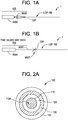
- the light diffusing optical fiber 100 (see Figures 2A , 2B , for example) has a glass core 110 with numerical aperture of NA LDF , an outer surface, and two ends 100' and 100".
- the glass core 110 includes a region 116 with a plurality of scattering structures 100A (e.g., micro- or nano-sized structures) within the core, and the scattering structures 100A are configured to scatter guided light towards the outer surface, providing scattering-induced attenuation greater than 50 dB/km at the illumination wavelength.
- the scatter guided light diffuses through the outer surface of the fiber to provide illumination.
- the light source 500 of the illumination device 1 has a numerical aperture of NA S1 , where NA LDF > NA S1 . While not being bound by theory, we realized that if a light source has a lower numerical aperture than the light diffusing optical fiber 100, then it takes a certain "diffusion distance" to completely fill the mode content of the light diffusing optical fiber 100.
- the low NA mode content of the light diffusing optical fiber 100 has a lower loss rate due to diffusivity than the higher NA modes. Therefore, because it takes a certain distance to completely fill the mode content of the light diffusing optical fiber 100, the brightness of at the beginning portion of the fiber (i.e., illumination provided by the LDF) does not immediately decrease with increasing fiber length due to light loss through diffusion. Instead, Applicants believe that as the mode content of light propagating through the fiber core increases, it compensates for the exponential decay in the intensity of light that is propagating through the core, achieving relatively uniform illumination along the fiber length.
- light source 500 may be is chosen such that NA LDF - NA S1 >0.02.
- NA LDF > 0.3, for example between 0.3 and 0.5.
- NA LDF may be 0.33, 0.35, 0.45, 0.48, 0.5 or therebetween.
- the difference between the numerical apertures between the light source(s) 500 and the fiber 100 and the choice of their NAs influences the length of the distance where the mode content of light diffusing optical fiber 100 becomes full.
- NA S1 ⁇ 0.3.
- NA S1 ⁇ 0.2, and in some embodiments NA S1 ⁇ 0.1.
- light source 500 comprises a light source component 500A coupled to the lens 500B.
- the light diffusing optical fiber 100 is thus optically coupled via fiber end 100' to a light source component 500A through the lens 500B.
- light source 500 comprises a light source component 500A coupled to the light delivery fiber 500C.
- the coupling between the light delivery fiber 500C and light diffusing optical fiber 100 can be done, for by a standard optical fiber coupler 500D, or by splicing the fiber end 100' of the light diffusing optical fiber 100 to the adjacent end of the delivery fiber 500C.
- the light diffusing optical fiber 100 is thus coupled via fiber end 100' to a light source component 500A via the delivery fiber 500C.
- a light diffusing fiber 100 may include one or more core regions with scattering structures, such as randomly distributed voids example.
- scattering structures such as randomly distributed voids example.
- Some examples of light-diffusing optical fibers having randomly arranged and randomly sized voids are described in U.S. Pat. No. 7,450,806 , and in U.S. patent application Ser. No. 12/950,045 .
- other scattering structures such as small light scattering particles, or dopants within the fiber core may also be utilized.
- the light diffusing fiber 100 may have a "roughened" core, where the irregularities on the surface of the core at the core-cladding interface causes light scatter.
- Light diffusing fibers 100 fiber may have scattering-induced attenuation (i.e., attenuation due to light lost through the outer surface of the fiber, not due to absorption of scattering particles within the core) greater than 50 dB/km, for example between 100 dB/km and 60000 dB/km at illumination wavelength.
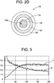
- Figure 3 illustrates the modeled light intensity, as light propagates through a 200 cm long light diffusing fiber 100.
- the core 110 includes a scattering region comprising scattering structures 100A (in this embodiment gas filled voids).
- the modeling was performed with the ray tracing software application ZEMAX, available from Radiant Zemax, LLC, of Redmond, WA, USA.
- the scattering region of the core (region 116 ) comprising the scattering structures 100A was modeled as a scattering volume characterized by the photon mean free path and the scattering angle.
- the modeled scattering mean free path is 3cm, and the scattering angle is 5°.
- MFP is the average distance that the light ray travels between two scattering events, and the scattering angle is the average angle between the ray directions before and after a single scattering event.
- a part of the scattering region has refractive index that is smaller than that of the silica core, and the rest of the scattering region is assumed to have an index close to the index of the silica core, mimicking penetration of the light guided in the scattering region 116 (e.g. a glass ring with gas filled voids 116 '). More specifically, in this embodiment, the scattering region 116 includes two layers 116A and 116B with gas filled voids.
- LDF light diffusing optical fiber
- NA S1 0.17.
- Figure 3 illustrates that in this embodiment of the illumination device 1, the light intensity in the first 1m length of fiber 100 increases due to gradual mode filling (plot A), and thus compensates for the intensity of light that is lost due to loss of light diffusing through the outer surface of the fiber.
- Figure 3 also illustrates modeled intensity of a comparative illumination device (plot B).
- the comparative device model utilized the same optical fiber 100, but the fiber was coupled to a light source with a numerical aperture of 0.36. As shown in Figure 4 in the comparative device, the intensity of the light propagating through a 200m length of the optical fiber continuously decreases, because the NA of the light source was larger than that of the fiber.
- the illumination system includes a single light diffusing fiber 100.
- the illumination device includes a plurality of light diffusing fibers. These light diffusing fiber(s) may be utilized in a straight configuration, or may be bent.
- an illumination device 1 comprises: (i) a light diffusing optical fiber or a side emitting fiber having a numerical aperture of NA LDF , wherein the light diffusing optical fiber has an outer surface, two ends, and a core, and a cladding, the fiber comprising a region with a plurality of scattering structures configured to scatter guided light via the scattering structures towards the outer surface providing scattering-induced attenuation greater than 50 dB/km (and preferably greater than 100 dB/km) at illumination wavelength, the scatter guided light diffuses through the outer surface to provide illumination; (ii) a light source having a numerical aperture of NA S1 , said light source being optically coupled to one end of said light diffusing optical fiber; NA LDF - NA S1 >0.05.
- the light diffusing fibers or side emitting fibers utilized in such an illumination devise may include scattering structures in fiber cladding, and/or on core/cladding interface.
- NA LDF - NA S1 >0.05, 0.05 ⁇ NA S1 ⁇ 0.3 and 0.31 ⁇ NA LDF ⁇ 0.52.
- NA LDF -NA S1 ⁇ 0.1.
- NA LDF -NA S1 ⁇ 0.15.
- the illumination device 1 further comprises a second light source 550.
- the first light source 500 is coupled to the other end 100 ' of the light diffusing optical fiber 100'
- the second light source 550 is coupled to another end 100 " of the light diffusing optical fiber 100.
- the second light source has a numerical aperture of NA S2 , wherein NA LDF >NA S2 , and preferably NA LDF - NA S2 >0.05.
- NA LDF - NA S2 ⁇ 0.1.
- the illumination device 1 further comprises a delivery fiber having a numerical aperture NA deiivery , wherein (i) the light source is coupled to one end the delivery fiber and the light diffusing optical fiber is coupled to another end of said delivery fiber, and NA deiivery ⁇ NA LDF .
- NA LDF - NA delivery >0.05.
- NA LDF - NA delivery ⁇ 0.1.
- the light diffusing fibers 100 can be easily connected to low loss delivery fiber 500C, such as transmission fiber or a fiber that provides light amplification (e.g., a fiber that includes gain medium in the core), thereby allowing a light source to be remotely placed away from light diffusing fiber 100.
- the transmission optical fiber 500C exhibits low light loss along its length, such that light in substantial portion delivered to one end is transmitted to a second end.
- light source 500 comprises a light source component 500A coupled transmission optical fiber 500C.
- light emitted by the light source component 500A is transmitted through the transmission optical fiber 500C to the light-diffusing optical fiber 100, which scatters the light into the surrounding environment.
- the transmission optical fiber exhibits low light loss
- light with sufficient intensity to illuminate the light-diffusing optical fiber 100 may be transmitted through the optical fiber 500C over an extended distance, such that the light source component 500A may be positioned at locations spaced apart from the light-diffusing optical fiber 100.
- the delivery fiber 500C is a laser fiber, or a fiber capable of providing light amplification
- light with sufficient intensity to illuminate the light-diffusing optical fiber 100 is transmitted through the optical fiber 500C and the light source component 500A may be positioned at locations spaced apart from the light-diffusing optical fiber 100.
- the light-diffusing optical fiber 100 may be separated from the light source component 500A electrically, structurally, and optically other than through an optical connection with a transmission optical fiber 500C. This helps to deal with heat dissipation and bring additional flexibility to the design of illumination devices.
- the light source component 500A may be positioned at a location remote from the light-diffusing optical fiber 100. Accordingly, any thermal heat generated by the light source component 500A may be transferred away from the light source light source component 500A at positions remote from the light-diffusing optical fiber 100.
- the thermal temperature of the light-diffusing optical fiber 100 therefore, may remain substantially similar to the ambient temperature of the surrounding environment and the lighting unit may be described as a thermally "cool" lighting unit.
- the illumination device 1 further comprises a reflective surface 600, such that one end 100' of the light diffusing optical fiber (LDF) 100 is coupled to the light source 500, and the reflective surface 600 is coupled to another end 100" of the light diffusing optical fiber.
- the light diffusing optical fiber (LDF) 100 is coupled to a low-cost reflective module 700 that includes the reflective surface 600.
- the reflective module 700 is detachable, allowing easy re-configuration of the illumination device 1.
- the reflective module 700 includes a tube 710, which is sized to fit over the standard FC type connector ferrule 720, such as reusable FC/PC connector used for 125 ⁇ m glass diameter fibers
- the inner diameter of the tube 710 is preferably about 2-5 ⁇ m wider than the outer diameter of the ferrule.
- Ferrule 720 is attached to the fiber 100 for easy connection to the reflective surface 600, at FC receptacle output port.
- the connector ferrule 720 fits snugly into the tube 720, but can pulled out if needed.
- the tube 710 is cut to have a cross-section perpendicular to the longitudinal axis plane, such that its axis is perpendicular to the reflective surface 600.
- the reflective surface 600 is provided by a small mirror 610, with dimensions 2mm x 2 mm, or less, and the tube 710 is attached to this mirror.
- Mirror 610 is attacked to the ferrule 720, and can be for example, a small glass plate (e.g., display glass 0.6 to 1.1 mm thick) with an aluminum coating, or a reflective film or coating.
- the light diffusing optical fiber (LDF) 100 can, when needed, be easily detached from the reflective module 700.
- the mirror 610 is cut of large sheet of thin (e.g., 0.7-1 mm) glass.
- the mirror 610 has a dielectric or metal coating reflective at the light source's wavelength (e.g., the wavelength provided by a laser diode, LD) and is glued to the tube 710.
- This simple fixture is attached to the ferrule, such that a cleaved and polished fiber tip touches the reflective surface 600.
- This exemplary embodiment of the reflective module 700 provides an effective and cost effective way of making end mirrors for lighting fixtures with single light a source for low cost LDF applications.
- Figure 7 illustrates modeled light intensity in another embodiment of the illumination device 1.
- the numerical aperture NA LDF of the light diffusing optical fiber 100 is 0.35
- light diffusing optical fiber 100 is coupled via fiber end 100' to a light source component 500A (blue laser diode, LD, providing light at wavelength of 445nm) through the lens 500B.
- the fiber 100 has a coating that includes Ce-Yag phosphor. The diameter of this fiber was 500 ⁇ m.
- This exemplary fiber provides white light illumination. The color conversion of blue light to white is done using Ce-Yag phosphor placed in the coating of the fiber 100.
- the output from lens 550B has numerical aperture of 0.22 and the lens creates spot size less than 80 ⁇ m in diameter at the fiber core at the end 100'.
- the spot is imaged onto the fiber core 110, which is 125 ⁇ m in diameter.
- NA LDF - NA S1 0.13.
- the other end 100" of the optical fiber 100 was attached to an aluminum mirror 600. That is, in this embodiment the illumination device 1 further comprises a reflective surface 600, such that one end 100' of the light diffusing optical fiber (LDF) 100 is coupled to the light source 500, and the reflective surface 600 is coupled to the end 100" of the light diffusing optical fiber 100.
- LDF light diffusing optical fiber
- a photograph of this fiber is shown in Figure 8 . This photograph illustrates that the fiber 100 appears to be uniform in intensity. That is, Figure 8 illustrates that this fiber provides uniform illumination (end-to-end).
- the use of yellow phosphor such as Ce-YAG placed on the surface of the fiber 100 enables making bright a flexible illumination device providing white color light.
- the brightness of the fiber is shown can exceed 10000 lux.
- the flexibility of thin glass fibers enables the light diffusing fiber 100 to be deployed in complex configurations and shapes in special lighting applications. Light from the fiber can also be coupled 100 into glass sheets for illumination purposes.
- the light source 500 generates light in the 200 nm to 500 nm wavelength range and fluorescent material in the light diffusing fiber 100 can generate either white, green, red, or NIR (near infrared) light.
- the wavelength of the light scattered by the fluorescent material is different from the wavelength of the light propagating in the fiber core.
- the light source 500 coupled to the LDF 100 generates light in 200 nm to 1200 nm wavelength range, which is determined by wavelength(d) of the light source (or multiple light sources).
- the light diffusing optical fiber further comprises a scattering/homogenizing coating surrounding the core.
- the scattering/homogenizing coating may include, for example, at least one of the following scattering materials: titania, alumina, zirconia, silica.
- the light diffusing optical fiber 100 generally comprises a core 110, which further comprises a scattering region.
- the scattering region may comprise scattering particles or scattering structures 100A, for example gas filled voids, such as shown in U.S. Appl. Ser. Nos. 12/950,045 , 13/097,208 , and 13/269,055 , or may comprise the inclusion of scattering particles, such as micro- or nanoparticles of ceramic materials, into the fiber core.
- the gas filled voids may occur throughout the fiber core 110, or may occur near the interface of the core and cladding 120, or may occur in an annular ring within the core.
- the gas filled voids may be arranged in a random or organized pattern and may run parallel to the length of the fiber or may be helical (i.e., rotating along the long axis of the fiber).
- the scattering region 116' may comprise a large number of gas filled voids, for example more than 50, more than 100, or more than 200 voids in the cross section of the fiber.
- the gas filled voids may contain, for example, SO 2 , Kr, Ar, CO 2 , N 2 , O 2 , or mixtures thereof.
- the cross-sectional size (e.g., diameter) of the voids (or other scattering particles) may be from about 10 nm to about 10 ⁇ m and the length may vary from about 1 ⁇ m to about 50 m.
- the cross sectional size of the voids (or other scattering particles) is about 10 nm, 20 nm, 30 nm, 40 nm, 50 nm, 60 nm, 70 nm, 80 nm, 90 nm, 100 nm, 120 nm, 140 nm, 160 nm, 180 nm, 200 nm, 250 nm, 300 nm, 400 nm, 500 nm, 600 nm, 700 nm, 800 nm, 1 ⁇ m, 2 ⁇ m, 3 ⁇ m, 4 ⁇ m, 5 ⁇ m, 6 ⁇ m, 7 ⁇ m, 8 ⁇ m, 9 ⁇ m, or 10 ⁇ m.
- the length of the voids is about 1 ⁇ m, 2 ⁇ m, 3 ⁇ m, 4 ⁇ m, 5 ⁇ m, 6 ⁇ m, 7 ⁇ m, 8 ⁇ m, 9 ⁇ m, 10 ⁇ m, 20 ⁇ m, 30 ⁇ m, 40 ⁇ m, 50 ⁇ m, 60 ⁇ m, 70 ⁇ m, 80 ⁇ m, 90 ⁇ m, 100 ⁇ m, 200 ⁇ m, 300 ⁇ m, 400 ⁇ m, 500 ⁇ m, 600 ⁇ m, 700 ⁇ m, 800 ⁇ m, 900 ⁇ m, 1000 ⁇ m, 5 mm, 10 mm, 50 mm, 100 mm, 500 mm, 1 m, 5 m, 10 m, 20 m, or 50 m.
- Figures 2A and 2B illustrate schematically an embodiment of light diffusing fiber (LDF) 100 with a modified coating 140 or a jacket surrounding the fiber for providing uniform angular scattering over a large angular range (e.g., 40° to 120°, or 30° to 130°, or 15 to 150°).
- LDF light diffusing fiber
- the illumination device 1 is configured to provide substantially uniform illumination due to scattering, such that the difference between the minimum and maximum scattering illumination intensity is less than 50% of the maximum scattering illumination intensity, for all viewing angles between 40 and 120 degrees.
- the light diffusing fiber of this exemplary embodiment includes a glass core 110 with a plurality of light scattering nanostructures (gas filled voids), a polymer cladding 120, and a secondary coating 130.
- the cladding 120 is glass.
- light diffusing fiber (LDF) 100 has a numerical aperture of NA LDF .
- Other light diffusing fibers or side emitting fibers with NA LDF such that NA LDF - NA S1 >0.05 (NA LDF - NA S1 >0.1) may also be utilized.
- the core portion 110 comprises silica-based glass and has an index of refraction, n.
- the index of refraction for the core is about 1.458.
- the core portion 110 may have a radius of from about 10 ⁇ m to about 600 ⁇ m. In other embodiments, the radius of the core is about 50 ⁇ m to about 100 ⁇ m. In some embodiment the radius of the core is from about 30 ⁇ m to about 400 ⁇ m. In other embodiments, the radius of the core is about 125 ⁇ m to about 300 ⁇ m.
- the radius of the core is about 50 ⁇ m, 60 ⁇ m, 70 ⁇ m, 80 ⁇ m, 90 ⁇ m, 100 ⁇ m, 120 ⁇ m, 140 ⁇ m, 160 ⁇ m, 180 ⁇ m, 200 ⁇ m, 220 ⁇ m, 240 ⁇ m, or 250 ⁇ m.
- the scattering particles and/or voids 110A in the core 110 are utilized to scatter light propagating in the core of the light diffusing optical fiber 100 such that the light is directed radially outward from the core portion 110, exiting the outer surface of the fiber, and thereby illuminating the light diffusing optical fiber and the space surrounding the light diffusing optical fiber.
- the scatter-induced attenuation may be increased through increasing the concentration of voids (or other scattering objects), positioning voids (or other scattering objects) throughout the fiber 100.
- the position of the voids are limited to a scattering region core 116 that is in a form of an annular ring (see Figure 4 , for example)
- increasing the width of the annulus comprising the voids will increase the scattering-induced attenuation for the same density of voids. That is, the magnitude of scattered light and thus the amount of scatter-induced attenuation depends on the size of the scattering structures 110A, their density, and the relative area of the scattering region 116 (relative to the overall size of the fiber core 110 ).
- the light diffusing optical fiber 100 may further comprise a cladding 120 which surrounds and is in direct contact with the core portion 110.
- the cladding 120 may be formed from a material which has a low refractive index (e.g., depressed index relative to silica) in order to increase the numerical aperture ( NA LDF ) of the light diffusing optical fiber 100.
- NA LDF numerical aperture
- the cladding has a refractive index of less than about 1.415, and preferably less than 1.35.
- the numerical aperture NA LDF of the light diffusing optical fiber 100 may be greater than about 0.3, and in some embodiments greater than about 0.4 or greater than 0.5.
- the cladding 120 comprises a low index polymeric material such as UV or thermally curable fluoroacrylate, such as PC452, available from SSCP Co. Ltd 403-2, Moknae, Ansan, Kyunggi, Korea, or silicone.
- the cladding comprises a urethane acrylate, such as CPC6, manufactured by DSM Desotech, Elgin, Ill.
- the cladding 120 comprises a silica glass which is down-doped with a down-dopant, such as, for example, fluorine or boron.
- the cladding comprises a high modulus coating.
- the cladding 120 generally has an index of refraction which is less than the index of refraction of the core portion 110.
- the cladding 120 is a low index polymer cladding with a relative refractive index that is negative relative to pure silica glass.
- the relative refractive index of the cladding may be less than about -0.5% and in some embodiments less than - 1%, relative to pure silica (which is considered to be at 0%).
- the cladding 120 generally extends from the outer radius of the core portion 110. In some embodiments described herein, the radial width of the cladding is greater than about 10 ⁇ m, greater than about 20 ⁇ m, greater than about 50 ⁇ m or greater than about 70 ⁇ m.
- the cladding has a thickness of about 10 ⁇ m, 20 ⁇ m, 30 ⁇ m, 40 ⁇ m, 50 ⁇ m, 60 ⁇ m, 70 ⁇ m, 80 ⁇ m, 90 ⁇ m, or 100 ⁇ m. If the glass core diameter is about 50 ⁇ m to 200 ⁇ m, and the cladding thickness is about 50 ⁇ m, the outer diameter of the uncoated fiber is 150-300 ⁇ m.
- the cladding 120 may be glass or polymer. Glass cladding 120 may be preferable when fiber is utilized in high power or UV applications.
- the absorption losses within the fiber 100 are negligible, and the scattering losses, and thus the amount of scatter-induced attenuation in some embodiments are 5 -7 dB/m.
- the bending induced losses can be small (if the NA LDF of the light diffusing fiber 100 is high, for example >0.35, bending losses are small), even with fiber bending radius as small as 5 mm.
- the light diffusing fiber 100 may also comprise a substantially clear layer corresponding to a secondary coating typical for all optical fibers for ease of mechanical handling.
- Figures 2A and 2B illustrate the light diffusing optical fiber 100 that comprises a secondary coating layer 130 which surrounds and is in direct contact with the cladding 120.
- the secondary layer may be a polymer coating.
- the coating layer 130 has a constant diameter along the length of the light diffusing optical fiber 100.
- the optical fiber 100 preferably includes a scattering layer or a scattering coating 140, or may be surrounded by a scattering jacket.
- the scattering (homogenizing) coating, jacket, or layer 140 may be situated on top of the secondary coating 130.
- the secondary coating layer and scattering layer may be combined into a single coating layer 140", depending on how the fiber is manufactured. This process is similar to post-draw ink application for optical fibers. However, it can be combined in one step in the draw, and in this case the secondary coating is not needed and the scattering/homogenizing layer 140 may be applied directly on top of the cladding.
- the coating, jacket or layer 140 comprises or is a scattering (homogenizing) layer and may be a polymer based coating.
- the scattering jacket or coating or layer 140 may comprise any liquid polymer or pre-polymer material into which the scattering agent could is added. It may be applied to the fiber as a liquid and then converted to a solid after application to the fiber.
- the scattering layer 140 comprises a polymer coating (such as, for example, the acrylate-based CPC6, manufactured by DSM Desotech, Elgin, 111), or a silicone-based polymer, further comprising a scattering material (e.g., nano or micro structures or voids).
- the scattering agents into standard UV curable acrylate based optical fiber coatings, such as Coming's standard CPC6 secondary optical fiber coating, thus combining the function of both layers 130 and 140 into a single coating 140" ( Figure 1C).
- a concentrate is first made by mixing 30% by weight of the scattering agent TiO 2 into DSM 950-111 secondary CPC6 optical fiber coating and then passing the mix over a 3 roll mill. These concentrates are then either applied directly as coatings or are further diluted with DSM 950-111 to produce the desired scattering effect.
- the locations of layers 140 and 130 may be switched ( Figure 2D ).
- the layer 140 may be surround the fiber 100 , but spaced from it.
- the scattering layer 140 or a fiber jacket may be utilized to enhance the distribution and/or the nature of the light emitted radially from the core portion 110 and passed through the optional cladding 120 and/or the optional layer 130.
- the scattering material in the jacket or layer 140 may comprise nano or microparticles with an average diameter of from about 200 nm to about 5 ⁇ m. In some embodiments, the average diameter of the particles is about 200 nm, 300 nm, 400 nm, 500 nm, 600 nm, 700 nm, 800 nm, 900 nm, 1 ⁇ m, 2 ⁇ m, 3 ⁇ m, 4 ⁇ m, 5 ⁇ m.
- the concentration of the scattering particles may vary along the length of the fiber or may be constant and may be a weight percent sufficient to provide even scattering of the light while limiting overall attenuation.
- the weight percentage of the scattering particles in the scattering layer comprises about 1%, 2%, 3%, 4%, 5%, 6%, 7%, 8%, 9%, 10%, 11%, 12%, 13%, 14%, 15%, 16%, 17%, 18%, 19%, 20%, 25%, 30%, 35%, 40%, 45%, or 50%.
- the scattering layer 140 comprises small particles of a scattering material which comprise a metal oxides or other high refractive index material, such as, for example, TiO 2 , ZnO, SiO 2 , or Zr.
- the scattering material may also comprise micro- or nanosized particles or voids of low refractive index, such as gas bubbles.
- the scattering layer 140 generally extends either from the outer radius of the cladding 120 or from the outer diameter of the coating layer 130 .
- the radial width of the scattering layer 140 is greater than about 1 ⁇ m, 2 ⁇ m, 3 ⁇ m, 4 ⁇ m, 5 ⁇ m, 6 ⁇ m, 7 ⁇ m, 8 ⁇ m, 9 ⁇ m, 10 ⁇ m, 20 ⁇ m, 30 ⁇ m, 40 ⁇ m, 50 ⁇ m, 60 ⁇ m, 70 ⁇ m, 80 ⁇ m, 90 ⁇ m, or 100 ⁇ m.
- the scattering material may contain TiO 2 -based particles, such as a white ink, which provides for an angle independent distribution of light scattered from the core portion 110 of the light diffusing optical fiber 100.
- the scattering particles comprise a sublayer within the scattering layer.
- the particle sublayer may have a thickness of about 1 ⁇ m to about 5 ⁇ m.
- the thickness of the particle layer and/or the concentration of the particles in the scattering layer may be varied along the axial length of the fiber so as to provide more uniform variation in the intensity of light scattered from the light diffusing optical fiber 100 at large angles (i.e., angles greater than about 15 degrees.
- the angular illumination for all viewing angles between 40 and 120 degrees is within 50% of maximum illumination, and in some embodiments within 30%. In some embodiments, the angular illumination for all viewing angles between 40 and 120 degrees is within 30% of maximum illumination, and in some embodiments within 25%.
- the scattering agent within the scattering layer 140 could be any scattering material that has a refractive index differential from the matrix of coating (i.e., e.g. from base polymer) material of more than 0.05 (e.g., the difference in refractive indices between polymer base and the scattering material is greater than 0.05).
- the difference in refractive indices between base material and the scattering material is at least 0.1. That is, the index of refraction of the scattering particles is preferably at least 0.1 larger than the index of refraction of the base material (e.g., of the polymer or other matrix material) of the scattering layer 140.
- the scattering material(s) can be solid particles, liquid droplets, or gas bubbles. If, for example, the scattering material is solid particles, these solid scattering particles can be either organic or inorganic. If the scattering material is organic, the particles can be pigments, polymers, or any organic material that can be incorporated into the base matrix material as a powder. Scattering agents can also be generated in-situ, via crystallization and/or phase separation.
- Examples of these are, but not limited to, polyethylene, polypropylene, syndiotactic polystyrene, nylon, polyethylene terephthalate, polyketones, and polyurethanes where the urethane functional groups align and crystallize during solidification.
- matrix materials such that the material mixture in the matrix becomes incompatible during cure or solidification, causing it to phase separate into droplets or particles that can scatter light, thus forming scattering sites.
- Example of these would be, but are not limited to, styrene-butadiene-styrene block copolymers, polymethyl methacrylate in polystyrene, and acrylonitrile-butadiene-styrene.
- the scattering particles can be, for example, pigments, oxides, or mineral fillers. Both the organics and inorganicse scattering particles can be generated, for example, from grinding a solid, or as small particles initially (, for example, from emulsion polymerization or solgels).
- the solid scattering particles (or scattering agents) are inorganic oxides like silica, alumina, zirconia, titania, cerium oxide, tin oxide, and antimony oxide. Ground glass, ceramics, or glass-ceramics can also be utilized as scattering agents.
- Ground silicates or mineral fillers like quartz, talc, mullite, cordierite, clay, nepheline syenite, calcium carbonate, aluminum trihydrate, barium sulfate, wallastonite, mica, feldspar, pyrophyllite, diatomite, perlite, and cristobalite can utilized in layer 140 as scattering particles, to provide the uniform angular illumination intensity of the diffused light.
- the cross-sectional size of the scattering particles within the scattering layer 140 is 0.1 ⁇ to 10 ⁇ , where ⁇ is the wavelength of light propagating through the light diffusing fiber 100.
- the cross-sectional size d of the scattering particles is greater than 0.2 ⁇ and less than 5 ⁇ , and more preferably between 0.5 ⁇ and to 2 ⁇ .
- the amount of scattering particles can vary from about 0.005% to 70% by weight, preferably 0.01 to 60% and most preferably 0.02 to 50%. In general, the thinner the scattering layer or scattering coating 140, the larger amount of scattering particles should to be present within that scattering layer.
- unscattered light propagates down the light diffusing fiber 100 from the source in the direction shown by arrow 150.
- Scattered light is shown exiting the light diffusing fiber as arrow 160 at an angle 170, which describes the angular difference between the direction of the fiber and the direction of the scattered light when it leaves light diffusing fiber 100.
- angle 170 describes the angular difference between the direction of the fiber and the direction of the scattered light when it leaves light diffusing fiber 100.
- the visible, and/or near IR spectrum of the light diffusing fiber 100 is independent of angle 170 .
- the intensities of the spectra when angle 170 is between 15° and 150°, or 30° and 130° are within ⁇ 50%, ⁇ 30%, ⁇ 25%, ⁇ 20%, ⁇ 15%, ⁇ 10%, or ⁇ 5% as measured at the peak wavelength.
- the illumination device 1 can provide uniform angular illumination, as well as uniform illumination along the length of the fiber(s) 100 .
- the intensities of the spectra when angle 170 is between all angles within 30° and 130°, or 40° and 120° are at least within ⁇ 50%, for example ⁇ 30%, ⁇ 25%, ⁇ 20%, ⁇ 15%, ⁇ 10%, or ⁇ 5% as measured at the peak wavelength.
- the illumination device 1 can provide uniform angular illumination, as well as uniform illumination along the length of the fiber(s) 100 . Accordingly, illumination device 1 is configured to provide substantially uniform illumination due to scattering, such that the difference between the minimum and maximum scattering illumination intensity is less than 50% of the maximum scattering illumination intensity, for all viewing angles between at least 40 degrees and 110 degrees, for example for all viewing angles between 40 degrees and 120 degrees. According to some embodiments, the difference between the minimum and maximum scattering illumination intensity is not greater than 30% of the maximum scattering illumination intensity.
- the light diffusing optical fibers will generally have a length from about 0.15 m to about 100 m.
- the light diffusing optical fibers for example, have a length of about 100 m, 75 m, 50 m, 40 m, 30 m, 20 m, 10 m, 9 m, 8 m, 7 m, 6 m, 5 m, 4 m, 3 m, 2 m, 1 m, 0.75 m, 0.5 m, 0.25 m, 0.15 m, or 0.1 m.
- the light diffusing optical fibers (LDFs) 100 described herein have a scattering induced attenuation loss of greater than about 0.2 dB/m at a wavelength of 550 nm.
- the scattering induced attenuation loss (attenuation loss due to scattering centers, such as air lines for example) may be greater than about 0.5 dB/m, 0.6 dB/m, 0.7 dB/m, 0.8 dB/m, 0.9 dB/m, 1 dB/m, 1.2 dB/m, 1.4 dB/m, 1.6 dB/m, 1.8 dB/m, 2.0 dB/m, 2.5 dB/m, 3.0 dB/m, 3.5 dB/m, or 4 dB/m, 5 dB/m, 6 dB/m, 7 dB/m, 8 dB/m, 9 dB/m, 10 dB/m, 20
- the light diffusing fiber can be constructed to produce uniform illumination along the entire length of the fiber or uniform illumination along a segment of the fiber which is less than the entire length of the fiber.
- uniform illumination when referring to the illumination along the length, as used herein, means that the intensity of light emitted from the light diffusing fiber does not vary by more than 25% over the specified length, L, where 0.1 ⁇ L ⁇ 100m. ⁇ 2 MIN
- the average scattering loss of the fiber is greater than 50 dB/km, and the scattering loss does not vary more than 20% (i.e., the scattering loss is within ⁇ 20% of the average scattering loss, for example within ⁇ 15%, or within ⁇ 10%) over any given fiber segment of 0.2 m length. In at least some embodiments, the average scattering loss of the fiber is greater than 50 dB/km, and the scattering loss does not vary more than 20% (i.e., the scattering loss is within ⁇ 20% of the average scattering loss, for example within ⁇ 15%, or even within ⁇ 10%) over any given fiber segment of 0.5 m length.
- the average scattering loss of the fiber is greater than 50 dB/km, and the scattering loss does not vary more than 20% (i.e., the scattering loss is within ⁇ 20% of the average scattering loss, for example within ⁇ 15%, or within ⁇ 10%) over any given fiber segment of 1 m length. In at least some embodiments, the average scattering loss of the fiber is greater than 50 dB/km, and the scattering loss does not vary more than 20% (i.e., the scattering loss is within ⁇ 20% of the average scattering loss, for example within ⁇ 15%, or within ⁇ 10%) over any given fiber segment of 3 m length.
- the average scattering loss of the fiber is greater than 50 dB/km, and the scattering loss does not vary more than 20% (i.e., the scattering loss is within ⁇ 20% of the average scattering loss, for example within ⁇ 15%, or within ⁇ 10%) over any given fiber segment of 5 m length. In at least some embodiments, the average scattering loss of the fiber is greater than 50 dB/km, and the scattering loss does not vary more than 15% (i.e., the scattering loss is within ⁇ 15% of the average scattering loss, for example within ⁇ 10%, or within ⁇ 5%) over any given fiber segment of 10 m length.
- the average scattering loss of the fiber is greater than 50 dB/km, and the scattering loss does not vary more than 20% (i.e., the scattering loss is within ⁇ 20% of the average scattering loss, for example within ⁇ 15%, or within ⁇ 10%) over any given fiber segment of 0.2m ⁇ L ⁇ 10m, 0.2m ⁇ L ⁇ 20m or 0.2 m ⁇ L ⁇ 50 m length.
- FIGs. 9A and 9B are schematic a plot of exemplary refractive index versus fiber radius for an example fiber 100 shown in FIG. 2A .
- the core 110 may have a graded core profile, characterized, for example, by an ⁇ -value between 1.7 and 2.3 (e.g., 1.8 to 2.3).
- the core region 112 extends radially outwardly from the centerline to its outer radius, R1 , and has a relative refractive index profile ⁇ 1 (r) corresponding to a maximum refractive index n1 (and relative refractive index percent ⁇ 1MAX ).
- the reference index n REF is the refractive index at the cladding.
- the second core region is a scattering region 116 (nano-structured region) having minimum refractive index n2, a relative refractive index profile ⁇ 2(r), and a minimum relative refractive index n2 MIN corresponding to ⁇ 2 MIN .
- the annular cladding 120 has a refractive index n4, a relative refractive index profile ⁇ 4(r) with a maximum relative refractive index ⁇ 4 MAX , and a minimum relative refractive index ⁇ 4 MIN .
- ⁇ 4 MAX ⁇ 4 MIN .
- core regions 112, 118 have a substantially constant refractive index profile, as shown in FIG. 9B with a constant ⁇ 1 (r) and ⁇ 3(r).
- ⁇ 2(r) is either slightly positive (e.g., 0 ⁇ ⁇ 2(r) ⁇ 0.1%), negative (e.g., -0.1% ⁇ ⁇ 2(r) ⁇ 0), or 0%.
- the absolute magnitude of ⁇ 2(r) is less than 0.1%, preferably less than 0.05%.
- the outer cladding region 120 has a substantially constant refractive index profile, as shown in FIG. 9B , with a constant ⁇ 4(r).
- ⁇ 4(r) 0%.
- the core section 112 has a refractive index where ⁇ 1(r) ⁇ 0%.
- the void-filled scattering region 116 has a relative refractive index profile ⁇ 2(r) having a negative refractive index with absolute magnitude less than 0.05%, and ⁇ 3(r) of the core region 118 can be, for example, positive or zero.
- the cladding 120 has a refractive index -0.05% ⁇ 4(r) ⁇ 0.05%. In other embodiments, the cladding 120 and the core portions 112, 116, and 118 may comprise pure (undoped) silica.
- the cladding 120 when cladding 120 is utilized, the cladding 120 comprises pure silica, F-doped silica, or F(fluorine)/B(boron) co-doped silica. In some embodiments, the cladding 120 comprises pure low index polymer. In some embodiments, scattering region 116 is nano-structured region that a comprises pure silica comprising a plurality of voids 116'. Preferably, the minimum relative refractive index and the average effective relative refractive index, taking into account the presence of any voids, of nano-structured scattering region 116 are both less than -0.1%.
- the scattering structures 110A are gas filled voids, for example airlines.
- the voids may contain one or more gases, such as argon (Ar), nitrogen (N 2 ), oxygen (O 2 ), krypton (Kr), CO 2 , or SO 2 , or mixtures thereof, or can contain a vacuum with substantially no gas.
- gases such as argon (Ar), nitrogen (N 2 ), oxygen (O 2 ), krypton (Kr), CO 2 , or SO 2 , or mixtures thereof, or can contain a vacuum with substantially no gas.
- the average refractive index in nano-structured region 116 is lowered due to the presence of voids.
- the scattering structures 110A such as voids can be randomly or non-periodically disposed in the nano-structured scattering region 116. In other embodiments the voids are disposed periodically within the in nano-structured scattering region 116.
- the core section 112 comprises germania doped silica
- the core inner annular region 118 comprises pure silica
- the cladding annular region 120 comprises a glass or a low index polymer.
- the nano-structured scattering region 116 comprises a plurality of voids 116' in pure silica; and in yet others of these embodiments, the nano-structured scattering region 116 comprises a plurality of voids 116' in fluorine-doped silica.
- the central portion 112 of the core 110 has a radius that is 0.1Rc ⁇ R 1 ⁇ 0.9Rc, preferably 0.5Rc ⁇ R 1 ⁇ 09Rc.
- the width W2 of the scattering region 116 (in this embodiment the width of the nano- structured region) is preferably 0.05Rc ⁇ W2 ⁇ 0.9Rc, preferably 0.1Rc ⁇ W2 ⁇ 0.9Rc, and in some embodiments 0.5Rc ⁇ W2 ⁇ 0.9Rc (a wider nano-structured region gives a higher scattering-induced attenuation, for the same density of nano-sized structures).
- Each section of the core 110 comprises silica based glass.
- the radial width W 2 of nano-structured scattering region 116 is preferably greater than 1 ⁇ m.
- W 2 may be 5 ⁇ m to 300 ⁇ m, and preferably 200 ⁇ m or less. In some embodiments, W 2 is greater than 2 ⁇ m and less than 100 ⁇ m. In other embodiments, W2 is greater than 2 ⁇ m and less than 50 ⁇ m. In other embodiments, W 2 is greater than 2 ⁇ m and less than 20 ⁇ m. In some embodiments, W 2 is at least 7 ⁇ m. In other embodiments, W 2 is greater than 2 ⁇ m and less than 12 ⁇ m.
- the width W 3 of the core region 118 is (R3-R2) and its midpoint R 3MID is (R2+ R3)/2. In some embodiments, W 3 is greater than 1 um and less than 100 ⁇ m.
- the numerical aperture (NA) of fiber 100 is equal to or greater than the NA of a light source directing light into the fiber.
- NA numerical aperture
- the numerical aperture (NA) of fiber 100 is greater than 0.2, in some embodiments greater than 0.3, and more preferably greater than 0.4.
- the core outer radius R1 of the first core region 112- is preferably not less than 24 ⁇ m and not more than 50 ⁇ m, i.e. the core diameter is between about 48 and 100 ⁇ m. In other embodiments, R1 > 24 microns; in still other embodiments, R1 > 30 microns; in yet other embodiments, R1 > 40 microns.
- the cladding 120 has a relative refractive index profile ⁇ 4(r) having a maximum absolute magnitude less than 0.1%, and in this embodiment ⁇ 4 MAX ⁇ 0.05% and ⁇ 4 MIN > -0.05.
- Cladding 120 extends to a radius R4, which is also the outermost periphery of the uncoated optical fiber.
- the width of the cladding, R4-R3, is greater than 20 ⁇ m; in other embodiments R4-R3 is at least 50 ⁇ m, and in some embodiments, R4-R3 is at least 70 ⁇ m.
- the entire core 110 is nano-structured (filled with voids 116', for example), and the core 110 is surrounded by the cladding 120.
- the entire core 110 is a void-filled scattering region 116.
- the core 110 may have a "step" refractive index delta, or may have a graded core profile, with the ⁇ -profile having, for example, ⁇ -value between 1.8 and 2.3.
- Other light diffusing fibers may utilize scattering structures situated at the core cladding boundary or in the cladding.
Description
- The disclosure generally relates to light diffusing optical fibers for use in illumination applications, and, more specifically, to light diffusing optical fibers and illumination devices utilizing such fibers.
-
WO 2011/06321 A1 US 2013/107565 A1 ,US 2012/275180 A1 andWO 2013/055842 relate to illumination devices that comprise light diffusing optical fibers. - According to the disclosure an illumination device includes a light source and at least one light diffusing optical fiber. The light source is coupled to the fiber and the numerical aperture of the light source is smaller than that of the fiber.
- More specifically, according to the invention, the illumination device comprises: (i) a light diffusing optical fiber having a numerical aperture of NALDF, wherein said light diffusing optical fiber has an outer surface, two ends, a core, and a cladding, the fiber comprising a region with a plurality of scattering structures configured to scatter guided light via the scattering structures towards the outer surface providing scattering-induced attenuation greater than 50 dB/km at illumination wavelength, wherein said scatter guided light diffuses through said outer surface to provide illumination; (ii) a light source having a numerical aperture of NAS1, the light source being optically coupled to one end of said light diffusing optical fiber; such that NALDF - NAS1 >0.05, 0.05≤ NAS1 ≤ 0.30 and 0.31≤ NALDF ≤ 0.52. In some embodiments, NALDF-NASI >0.02. According to some embodiments the fiber is surrounded by a scattering coating or a jacket that improves angular scattering, and thus angular illumination.
- According to some embodiments, the illumination device comprises:
- (i) a light diffusing optical fiber having a numerical aperture of NALDF, wherein said light diffusing optical fiber has an outer surface, two ends, and a glass core comprising a region with a plurality of scattering structures within said core configured to scatter guided light via said scattering structures towards the outer surface providing scattering-induced attenuation greater than 50 dB/km at illumination wavelength, wherein said scatter guided light diffuses through said outer surface to provide illumination; (ii) a light source having a numerical aperture of NAS1, said light source being optically coupled to one end of said light diffusing optical fiber; NALDF - NAS1 >0.05, 0.05≤ NAS1 ≤ 0.30 and 0.31≤ NALDF ≤ 0.52. In some embodiments, NALDF-NASI >0.02. According to some embodiments the fiber is surrounded by a scattering coating or a jacket that improves angular scattering, and thus angular illumination.
- According to the embodiments described herein, the illumination device provides a substantially uniform illumination due to scattering, such that the difference between the minimum and maximum scattering illumination intensity is less than 50% of the maximum scattering illumination intensity, for all viewing angles between 40 and 120 degrees.
- According to some embodiments, the illumination device comprises:
- (i) a light diffusing optical fiber having a numerical aperture of NALDF, wherein said light diffusing optical fiber has an outer surface, two ends, and a glass core comprising a region with a plurality of nano-sized structures within said core configured to scatter guided light via said nano-sized structures towards the outer surface providing scattering-induced attenuation greater than 50 dB/km at illumination wavelength, wherein the scatter guided light diffuses through said outer surface to provide illumination;
- (ii) a light source having a numerical aperture of NAS1, said light source being optically coupled to one end of said light diffusing optical fiber; and wherein NALDF - NAS1 >0.02.
- According to some embodiments the light source coupled to the fiber generates light in 200 nm to 500 nm wavelength range and fluorescent material in the fiber coating generates either white, green, red, blue, or NIR (near infrared) light. According to some embodiments the light source coupled to the fiber generates light in 200 nm to 1200 nm wavelength range.
- According to some embodiments, the illumination device includes a single light diffusing fiber. According to other embodiments the illumination system includes a plurality of light diffusing fibers. The light diffusing fibers may be utilized in a straight configuration, or may be bent. The light diffusing fibers fiber may have scattering-induced attenuation between 100 dB/km and 60000 dB/km at illumination wavelength.
- According to the invention, NALDF - NAS1 >0.05. According to the invention, 0.05≤ NAS1 ≤ 0.3. According to the invention, 0.31≤ NALDF ≤ 0.52.
- According to some embodiments the illumination device further comprises a second light source. The second light souse is coupled to another end of the light diffusing optical fiber. The second light source has a numerical aperture of NAS2, wherein NALDF - NAS2 >0.02. Preferably, NALDF - NAS2 >0.05. Also preferably, 0.05≤ NAS2 ≤ 0.3.
- According to some embodiments the illumination device further comprises a delivery fiber having a numerical aperture NAdelivery, wherein (i) the light source is coupled to one end said delivery fiber and the light diffusing optical fiber is coupled to another end of said delivery fiber, and NAdelivery< NALDF.
- According to some embodiments of the illumination device the light diffusing optical fiber further comprises a light scattering/homogenizing coating surrounding the fiber cladding or a protective coating layer. The scattering/homogenizing coating may include at least one of the following scattering materials: titania, alumina, silica.
- Reference is now made in detail to the present preferred embodiments of the invention, examples of which are illustrated in the accompanying drawings. Whenever possible, like or similar reference numerals are used throughout the drawings to refer to like or similar parts. It should be understood that the embodiments disclosed herein are merely examples, each incorporating certain benefits of the present invention.
- Various modifications and alterations may be made to the following examples within the scope of the present invention, and aspects of the different examples may be mixed in different ways to achieve yet further examples. Accordingly, the true scope of the invention is to be understood from the entirety of the present disclosure, in view of but not limited to the embodiments described herein
-
Figures 1A and 1B illustrate schematically two embodiments of illumination device that includes a light diffusing fiber. -
Figures 2A through 2D are schematic illustrations of several embodiments of light diffusing fibers (LDF). -
Figure 3 illustrates the modeled light intensity of one embodiment of illumination device, as light is propagating through 200 cm long length of light diffusing fiber. -
Figure 4 illustrates schematically another embodiment of light diffusing fiber. -
Figure 5 illustrates schematically another embodiment of the illumination device that includes a light diffusing fiber and two light sources coupled to the opposite ends of this fiber. -
Figure 6 illustrates schematically yet another embodiment of the illumination device that includes a light diffusing fiber, a light source coupled to one end of the fiber and a reflective surface situated on the other end of the fiber. -
Figure 7 is a plot of measured intensity along the length of light diffusing fiber of the illumination device ofFigure 6 . -
Figure 8 is a photograph of light diffusing fiber that corresponds toFigure 7 . -
Figures 9A and 9B are schematic illustrations of the relative refractive index profiles exemplary embodiments of light diffusing fiber. - The present disclosure is provided as an enabling teaching and can be understood more readily by reference to the following description, drawings, examples, and claims. To this end, those skilled in the relevant art will recognize and appreciate that many changes can be made to the various aspects of the embodiments described herein, while still obtaining the beneficial results. It will also be apparent that some of the desired benefits of the present embodiments can be obtained by selecting some of the features without utilizing other features. Accordingly, those who work in the art will recognize that many modifications and adaptations are possible and can even be desirable in certain circumstances and are a part of the present disclosure. Therefore, it is to be understood that this disclosure is not limited to the specific compositions, articles, devices, and methods disclosed unless otherwise specified. It is also to be understood that the terminology used herein is for the purpose of describing particular aspects only and is not intended to be limiting.
- Disclosed are materials, compounds, compositions, and components that can be used for, can be used in conjunction with, can be used in preparation for, or are embodiments of the disclosed method and compositions. These and other materials are disclosed herein, and it is understood that when combinations, subsets, interactions, groups, etc. of these materials are disclosed that while specific reference of each various individual and collective combinations and permutation of these compounds may not be explicitly disclosed, each is specifically contemplated and described herein. Thus, if a class of substituents A, B, and/or C are disclosed as well as a class of substituents D, E, and/or F, and an example of a combination embodiment, A-D is disclosed, then each is individually and collectively contemplated. Thus, in this example, each of the combinations A-E, A-F, B-D, B-E, B-F, C-D, C-E, and C-F are specifically contemplated and should be considered disclosed from disclosure of A, B, and/or C; D, E, and/or F; and the example combination A-D. Likewise, any subset or combination of these is also specifically contemplated and disclosed. Thus, for example, the sub-group of A-E, B-F, and C-E are specifically contemplated and should be considered disclosed from disclosure of A, B, and/or C; D, E, and/or F; and the example combination A-D. This concept applies to all aspects of this disclosure including, but not limited to any components of the compositions and steps in methods of making and using the disclosed compositions. Thus, if there are a variety of additional steps that can be performed it is understood that each of these additional steps can be performed with any specific embodiment or combination of embodiments of the disclosed methods, and that each such combination is specifically contemplated and should be considered disclosed.
- In this specification and in the claims which follow, reference will be made to a number of terms which shall be defined to have the following meanings:
"Include," "includes," or like terms means encompassing but not limited to, that is, inclusive and not exclusive. - The term "about" references all terms in the range unless otherwise stated. For example, about 1, 2, or 3 is equivalent to about 1, about 2, or about 3, and further comprises from about 1-3, from about 1-2, and from about 2-3. Specific and preferred values disclosed for compositions, components, ingredients, additives, and like aspects, and ranges thereof, are for illustration only; they do not exclude other defined values or other values within defined ranges. The compositions and methods of the disclosure include those having any value or any combination of the values, specific values, more specific values, and preferred values described herein.
- The indefinite article "a" or "an" and its corresponding definite article "the" as used herein means at least one, or one or more, unless specified otherwise.
- The "refractive index profile" is the relationship between the refractive index or the relative refractive index and the waveguide (fiber) radius.
- The "relative refractive index percent" is defined as

- An "updopant" is herein considered to be a dopant which has a propensity to raise the refractive index relative to pure undoped SiO2. A "downdopant" is herein considered to be a dopant which has a propensity to lower the refractive index relative to pure undoped SiO2. An updopant may be present in a region of an optical fiber having a negative relative refractive index when accompanied by one or more other dopants which are not updopants. Likewise, one or more other dopants which are not updopants may be present in a region of an optical fiber having a positive relative refractive index. A downdopant may be present in a region of an optical fiber having a positive relative refractive index when accompanied by one or more other dopants which are not downdopants.
- Likewise, one or more other dopants which are not downdopants may be present in a region of an optical fiber having a negative relative refractive index.
- The term "a-profile" or "alpha profile" refers to a relative refractive index profile, expressed in terms of Δ(r) which is in units of "%", where r is the radius, which follows the equation,

- As used herein, the term "parabolic" therefore includes substantially parabolically shaped refractive index profiles which may vary slightly from an α value of 2.0 at one or more points in the core, as well as profiles with minor variations and/or a centerline dip. In some exemplary embodiments, α is greater than 1.5 and less than 2.5, more preferably greater than 1.7 and 2.3 and even more preferably between 1.8 and 2.3 as measured at 850 nm. In other embodiments, one or more segments of the refractive index profile have a substantially step index shape with an α value greater than 8, more preferably greater than 10, and even more preferably greater than 20 as measured at 850 nm.
- As used herein, the term "step- index" profile includes refractive index profiles with constant refractive index in the core, at different radial position within the core.
- A desirable attribute of at least some of the embodiments of the present invention described herein is an illumination device that utilizes light diffusing fiber and provides uniform and high illumination along the length of the fiber.
- In at least some embodiments, the intensity variation of the integrated (diffused) light intensity coming through the sides of the fiber at the illumination wavelength is less than 20% for the target length of the fiber, which can be, for example, 0.02m - 100 m length (e.g., 0.2 m to 10 m). Such fibers could be used, for example, as replacements for other conventional lighting objects, but have the additional advantages of: (i) being much thinner than conventional light sources, and therefore can be used with thin illuminating substrates; and/or (ii) being able to function as a cool light source- i.e., the light diffusing fiber does not heat up while producing the required illumination- this feature is advantageous when the
fibers 100, or fiber bundles or fiber ribbons containing such fibers are used in environments that have to stay cold, or in the areas where they are used as a light source that is easily accessible to children or others, without a threat of potentially burning someone when handled directly. - A typical fiber system includes a light source coupled to a fiber where, in order to provide as much light intensity into the fiber core as possible, the light source has a numerical apertures equal to that of the optical fiber. In typical light diffusing fibers, light escapes from the fiber core, and the intensity of light diffused out of the outer surface of such fiber is reduced as the light propagates along the length of the fiber, due to immediate exponential decay in the intensity of the light that is propagating through the core. However, the embodiments of the present invention disclosed herein solve this problem by providing light that is uniform in intensity, as a function of fiber length.
- Referring to
Figure 1A and 1B , according to some embodiments anillumination device 1 includes at least one light diffusing optical fiber (LDF) 100 optically coupled to thelight source 500. The term "light-diffusing" means that light scattering is substantially spatially continuous along at least a portion of the length of the light-diffusingoptical fiber 100, i.e., there are no substantial jumps or discontinuities such as those associated with discrete (e.g., point) scattering. Thus, the concept of substantially continuous light emission or substantially continuous light scattering as set forth in the present disclosure refers to spatial continuity. The light diffusing optical fiber 100 (seeFigures 2A ,2B , for example) has aglass core 110 with numerical aperture of NALDF , an outer surface, and twoends 100' and 100". Theglass core 110 includes aregion 116 with a plurality of scattering structures 100A (e.g., micro- or nano-sized structures) within the core, and the scattering structures 100A are configured to scatter guided light towards the outer surface, providing scattering-induced attenuation greater than 50 dB/km at the illumination wavelength. The scatter guided light diffuses through the outer surface of the fiber to provide illumination. Thelight source 500 of theillumination device 1 has a numerical aperture of NAS1 , where NALDF > NAS1. While not being bound by theory, we realized that if a light source has a lower numerical aperture than the light diffusingoptical fiber 100, then it takes a certain "diffusion distance" to completely fill the mode content of the light diffusingoptical fiber 100. In this regard, without willing to be bound to any theory, we realized that in light diffusing fibers, the low NA mode content of the light diffusingoptical fiber 100 has a lower loss rate due to diffusivity than the higher NA modes. Therefore, because it takes a certain distance to completely fill the mode content of the light diffusingoptical fiber 100, the brightness of at the beginning portion of the fiber (i.e., illumination provided by the LDF) does not immediately decrease with increasing fiber length due to light loss through diffusion. Instead, Applicants believe that as the mode content of light propagating through the fiber core increases, it compensates for the exponential decay in the intensity of light that is propagating through the core, achieving relatively uniform illumination along the fiber length. For example,light source 500 may be is chosen such that NALDF - NAS1 >0.02. According to some embodiments, NALDF > 0.3, for example between 0.3 and 0.5. For example, according to some embodiments, NALDF may be 0.33, 0.35, 0.45, 0.48, 0.5 or therebetween. The difference between the numerical apertures between the light source(s) 500 and thefiber 100 and the choice of their NAs influences the length of the distance where the mode content of light diffusingoptical fiber 100 becomes full. Thus, given a particular length of the light diffusing fiber, one can chose the numerical aperture(s) of the light source(s) and that of the fiber to provide more uniform illumination along the length of the light diffusingoptical fiber 100. According to some embodiments, NAS1 <0.3. According to some embodiments, NAS1 <0.2, and in some embodiments NAS1 <0.1. - In the embodiment depicted in
Figure 1A ,light source 500 comprises alight source component 500A coupled to thelens 500B. The light diffusingoptical fiber 100 is thus optically coupled via fiber end 100' to alight source component 500A through thelens 500B. In the embodiment depicted inFigure 1B ,light source 500 comprises alight source component 500A coupled to thelight delivery fiber 500C. The coupling between thelight delivery fiber 500C and light diffusingoptical fiber 100 can be done, for by a standardoptical fiber coupler 500D, or by splicing the fiber end 100' of the light diffusingoptical fiber 100 to the adjacent end of thedelivery fiber 500C. The light diffusingoptical fiber 100 is thus coupled via fiber end 100' to alight source component 500A via thedelivery fiber 500C. - A
light diffusing fiber 100 may include one or more core regions with scattering structures, such as randomly distributed voids example. Some examples of light-diffusing optical fibers having randomly arranged and randomly sized voids (also referred to as "random air lines" or "nanostructures" or "nano-sized structures") are described inU.S. Pat. No. 7,450,806 , and inU.S. patent application Ser. No. 12/950,045 . Alternatively, other scattering structures such as small light scattering particles, or dopants within the fiber core may also be utilized. Also, alternatively, thelight diffusing fiber 100 may have a "roughened" core, where the irregularities on the surface of the core at the core-cladding interface causes light scatter. Other types of light diffusing fibers may also be utilized.Light diffusing fibers 100 fiber may have scattering-induced attenuation (i.e., attenuation due to light lost through the outer surface of the fiber, not due to absorption of scattering particles within the core) greater than 50 dB/km, for example between 100 dB/km and 60000 dB/km at illumination wavelength. - For example,
Figure 3 illustrates the modeled light intensity, as light propagates through a 200 cm longlight diffusing fiber 100. This exemplary fiber embodiment is illustrated inFigure 4 . It includes a core 110 that is 62.5µm in radius with an index of refraction n=1.46 at λ=589.3 nm. Thecore 110 includes a scattering region comprising scattering structures 100A (in this embodiment gas filled voids). The modeling was performed with the ray tracing software application ZEMAX, available from Radiant Zemax, LLC, of Redmond, WA, USA. The scattering region of the core (region 116) comprising the scattering structures 100A was modeled as a scattering volume characterized by the photon mean free path and the scattering angle. The modeled scattering mean free path (MFP) is 3cm, and the scattering angle is 5°. (MFP is the average distance that the light ray travels between two scattering events, and the scattering angle is the average angle between the ray directions before and after a single scattering event.) A part of the scattering region has refractive index that is smaller than that of the silica core, and the rest of the scattering region is assumed to have an index close to the index of the silica core, mimicking penetration of the light guided in the scattering region 116 (e.g. a glass ring with gas filled voids 116'). More specifically, in this embodiment, thescattering region 116 includes twolayers illumination device 1 includes at least one light diffusing optical fiber (LDF) 100 optically coupled to thelight source 500, where thelight source 500 has NAS1 =0.17. Thus, NALDF > NAS1, and more specifically NALDF - NAS1=0.17.Figure 3 illustrates that in this embodiment of theillumination device 1, the light intensity in the first 1m length offiber 100 increases due to gradual mode filling (plot A), and thus compensates for the intensity of light that is lost due to loss of light diffusing through the outer surface of the fiber.Figure 3 also illustrates modeled intensity of a comparative illumination device (plot B). The comparative device model utilized the sameoptical fiber 100, but the fiber was coupled to a light source with a numerical aperture of 0.36. As shown inFigure 4 in the comparative device, the intensity of the light propagating through a 200m length of the optical fiber continuously decreases, because the NA of the light source was larger than that of the fiber. - According to some embodiments, the illumination system includes a single
light diffusing fiber 100. According to other embodiments the illumination device includes a plurality of light diffusing fibers. These light diffusing fiber(s) may be utilized in a straight configuration, or may be bent. - It is noted different types of light diffusing fibers or side emitting fibers may also be utilized in the
illumination device 1. Thus, anillumination device 1 comprises: (i) a light diffusing optical fiber or a side emitting fiber having a numerical aperture of NALDF, wherein the light diffusing optical fiber has an outer surface, two ends, and a core, and a cladding, the fiber comprising a region with a plurality of scattering structures configured to scatter guided light via the scattering structures towards the outer surface providing scattering-induced attenuation greater than 50 dB/km (and preferably greater than 100 dB/km) at illumination wavelength, the scatter guided light diffuses through the outer surface to provide illumination; (ii) a light source having a numerical aperture of NAS1, said light source being optically coupled to one end of said light diffusing optical fiber; NALDF - NAS1 >0.05. The light diffusing fibers or side emitting fibers utilized in such an illumination devise may include scattering structures in fiber cladding, and/or on core/cladding interface. According to the invention NALDF - NAS1 >0.05, 0.05≤ NAS1 ≤ 0.3 and 0.31≤ NALDF ≤ 0.52. In some exemplary embodiments, NALDF -NAS1 ≥0.1. In some exemplary embodiments, NALDF -NAS1 ≥0.15. - As shown in
Figure 5 , according to some embodiments theillumination device 1 further comprises a second light source 550. In this exemplary embodiment the firstlight source 500 is coupled to the other end 100' of the light diffusing optical fiber 100', and the second light source 550 is coupled to anotherend 100" of the light diffusingoptical fiber 100. The second light source has a numerical aperture of NAS2 , wherein NALDF >NAS2, and preferably NALDF - NAS2 >0.05. For example, in some embodiments, NALDF - NAS2 ≥0.1. Also preferably, 0.05≤ NAS2 ≤ 0.3. - With reference to
Figure 1B , according to some embodiments theillumination device 1 further comprises a delivery fiber having a numerical aperture NAdeiivery, wherein (i) the light source is coupled to one end the delivery fiber and the light diffusing optical fiber is coupled to another end of said delivery fiber, and NAdeiivery< NALDF. For example, in some embodiments, preferably NALDF - NAdelivery>0.05. For example, in some embodiments, NALDF - NAdelivery≥0.1. Thelight diffusing fibers 100 can be easily connected to lowloss delivery fiber 500C, such as transmission fiber or a fiber that provides light amplification (e.g., a fiber that includes gain medium in the core), thereby allowing a light source to be remotely placed away from light diffusingfiber 100. For example, thedelivery fiber 500C can be standard multimode fiber with 50 µm core diameter, NAdeiivery = 0.22, or 62.5 µn core diameter, NAdelivery =0.22, or 105 µm core diameter, NAdelivery = 0.22. The transmissionoptical fiber 500C exhibits low light loss along its length, such that light in substantial portion delivered to one end is transmitted to a second end. In the embodiment depicted inFigure 1B ,light source 500 comprises alight source component 500A coupled transmissionoptical fiber 500C. In this embodiment, light emitted by thelight source component 500A is transmitted through the transmissionoptical fiber 500C to the light-diffusingoptical fiber 100, which scatters the light into the surrounding environment. Because the transmission optical fiber exhibits low light loss, light with sufficient intensity to illuminate the light-diffusingoptical fiber 100 may be transmitted through theoptical fiber 500C over an extended distance, such that thelight source component 500A may be positioned at locations spaced apart from the light-diffusingoptical fiber 100. Similarly, if thedelivery fiber 500C is a laser fiber, or a fiber capable of providing light amplification, light with sufficient intensity to illuminate the light-diffusingoptical fiber 100 is transmitted through theoptical fiber 500C and thelight source component 500A may be positioned at locations spaced apart from the light-diffusingoptical fiber 100. In some embodiments, the light-diffusingoptical fiber 100 may be separated from thelight source component 500A electrically, structurally, and optically other than through an optical connection with a transmissionoptical fiber 500C. This helps to deal with heat dissipation and bring additional flexibility to the design of illumination devices. - Because light emitted by the
light source component 500A is scattered into the surrounding environment by the light-diffusingoptical fiber 100, thelight source component 500A may be positioned at a location remote from the light-diffusingoptical fiber 100. Accordingly, any thermal heat generated by thelight source component 500A may be transferred away from the light sourcelight source component 500A at positions remote from the light-diffusingoptical fiber 100. The thermal temperature of the light-diffusingoptical fiber 100, therefore, may remain substantially similar to the ambient temperature of the surrounding environment and the lighting unit may be described as a thermally "cool" lighting unit. - As shown in
Figure 6 , according to some embodiments, theillumination device 1 further comprises areflective surface 600, such that one end 100' of the light diffusing optical fiber (LDF) 100 is coupled to thelight source 500, and thereflective surface 600 is coupled to anotherend 100" of the light diffusing optical fiber. For example, in some embodiments, the light diffusing optical fiber (LDF) 100 is coupled to a low-costreflective module 700 that includes thereflective surface 600. In this embodiment thereflective module 700 is detachable, allowing easy re-configuration of theillumination device 1. - In the embodiment of
Figure 6 , thereflective module 700 includes atube 710, which is sized to fit over the standard FCtype connector ferrule 720, such as reusable FC/PC connector used for 125 µm glass diameter fibers The inner diameter of thetube 710 is preferably about 2-5 µm wider than the outer diameter of the ferrule.Ferrule 720 is attached to thefiber 100 for easy connection to thereflective surface 600, at FC receptacle output port. Theconnector ferrule 720 fits snugly into thetube 720, but can pulled out if needed. Thetube 710 is cut to have a cross-section perpendicular to the longitudinal axis plane, such that its axis is perpendicular to thereflective surface 600. In this embodiment thereflective surface 600 is provided by asmall mirror 610, with dimensions 2mm x 2 mm, or less, and thetube 710 is attached to this mirror.Mirror 610 is attacked to theferrule 720, and can be for example, a small glass plate (e.g., display glass 0.6 to 1.1 mm thick) with an aluminum coating, or a reflective film or coating. The light diffusing optical fiber (LDF) 100 can, when needed, be easily detached from thereflective module 700. In this embodiment, themirror 610 is cut of large sheet of thin (e.g., 0.7-1 mm) glass. Themirror 610 has a dielectric or metal coating reflective at the light source's wavelength (e.g., the wavelength provided by a laser diode, LD) and is glued to thetube 710. This simple fixture is attached to the ferrule, such that a cleaved and polished fiber tip touches thereflective surface 600. This exemplary embodiment of thereflective module 700 provides an effective and cost effective way of making end mirrors for lighting fixtures with single light a source for low cost LDF applications. -
Figure 7 illustrates modeled light intensity in another embodiment of theillumination device 1. In this embodiment, the numerical aperture NALDF of the light diffusingoptical fiber 100 is 0.35, thefiber 100 has a length L=1.5 m, and thelight source 500 has a numerical aperture NAS1 =0.2. More specifically, light diffusingoptical fiber 100 is coupled via fiber end 100' to alight source component 500A (blue laser diode, LD, providing light at wavelength of 445nm) through thelens 500B. Thefiber 100 has a coating that includes Ce-Yag phosphor. The diameter of this fiber was 500µm. This exemplary fiber provides white light illumination. The color conversion of blue light to white is done using Ce-Yag phosphor placed in the coating of thefiber 100. The output from lens 550B has numerical aperture of 0.22 and the lens creates spot size less than 80 µm in diameter at the fiber core at the end 100'. The spot is imaged onto thefiber core 110, which is 125µm in diameter. In this embodiment, NALDF - NAS1=0.13. Theother end 100" of theoptical fiber 100 was attached to analuminum mirror 600. That is, in this embodiment theillumination device 1 further comprises areflective surface 600, such that one end 100' of the light diffusing optical fiber (LDF) 100 is coupled to thelight source 500, and thereflective surface 600 is coupled to theend 100" of the light diffusingoptical fiber 100. - More specifically,
Figure 7 illustrates light intensity distribution measured with a CCD camera along the length of this fiber embodiment. Uniformity from one end of the optical fiber to the other end of theoptical fiber 100 of this embodiment is about 90 % (min intensity/max intensity=0.9). A photograph of this fiber is shown inFigure 8 . This photograph illustrates that thefiber 100 appears to be uniform in intensity. That is,Figure 8 illustrates that this fiber provides uniform illumination (end-to-end). The use of yellow phosphor such as Ce-YAG placed on the surface of thefiber 100 enables making bright a flexible illumination device providing white color light. The brightness of the fiber is shown can exceed 10000 lux. The flexibility of thin glass fibers enables thelight diffusing fiber 100 to be deployed in complex configurations and shapes in special lighting applications. Light from the fiber can also be coupled 100 into glass sheets for illumination purposes. - Preferably, according to some embodiments the
light source 500 generates light in the 200 nm to 500 nm wavelength range and fluorescent material in thelight diffusing fiber 100 can generate either white, green, red, or NIR (near infrared) light. The wavelength of the light scattered by the fluorescent material is different from the wavelength of the light propagating in the fiber core. According to some embodiments thelight source 500 coupled to theLDF 100 generates light in 200 nm to 1200 nm wavelength range, which is determined by wavelength(d) of the light source (or multiple light sources). - According to some embodiments of the illumination device the light diffusing optical fiber further comprises a scattering/homogenizing coating surrounding the core. The scattering/homogenizing coating may include, for example, at least one of the following scattering materials: titania, alumina, zirconia, silica.
- Referring now to
Figures 2A and2B , one embodiment of a light diffusingoptical fiber 100 is schematically depicted. The light diffusingoptical fiber 100 generally comprises acore 110, which further comprises a scattering region. The scattering region may comprise scattering particles or scattering structures 100A, for example gas filled voids, such as shown in U.S. Appl. Ser. Nos.12/950,045 13/097,208 13/269,055 - For example, the gas filled voids (e.g., air lines) may occur throughout the
fiber core 110, or may occur near the interface of the core andcladding 120, or may occur in an annular ring within the core. The gas filled voids may be arranged in a random or organized pattern and may run parallel to the length of the fiber or may be helical (i.e., rotating along the long axis of the fiber). The scattering region 116' may comprise a large number of gas filled voids, for example more than 50, more than 100, or more than 200 voids in the cross section of the fiber. The gas filled voids may contain, for example, SO2, Kr, Ar, CO2, N2, O2, or mixtures thereof. The cross-sectional size (e.g., diameter) of the voids (or other scattering particles) may be from about 10 nm to about 10 µm and the length may vary from about 1 µm to about 50 m. In some embodiments, the cross sectional size of the voids (or other scattering particles) is about 10 nm, 20 nm, 30 nm, 40 nm, 50 nm, 60 nm, 70 nm, 80 nm, 90 nm, 100 nm, 120 nm, 140 nm, 160 nm, 180 nm, 200 nm, 250 nm, 300 nm, 400 nm, 500 nm, 600 nm, 700 nm, 800 nm, 1 µm, 2 µm, 3 µm, 4 µm, 5 µm, 6 µm, 7 µm, 8 µm, 9 µm, or 10 µm. In some embodiments, the length of the voids is about 1 µm, 2 µm, 3 µm, 4 µm, 5 µm, 6 µm, 7 µm, 8 µm, 9 µm, 10 µm, 20 µm, 30 µm, 40 µm, 50 µm, 60 µm, 70 µm, 80 µm, 90 µm, 100 µm, 200 µm, 300 µm, 400 µm, 500 µm, 600 µm, 700 µm, 800 µm, 900 µm, 1000 µm, 5 mm, 10 mm, 50 mm, 100 mm, 500 mm, 1 m, 5 m, 10 m, 20 m, or 50 m. - More specifically,
Figures 2A and2B illustrate schematically an embodiment of light diffusing fiber (LDF) 100 with a modifiedcoating 140 or a jacket surrounding the fiber for providing uniform angular scattering over a large angular range (e.g., 40° to 120°, or 30° to 130°, or 15 to 150°). For example, according to the exemplary embodiments disclosed herein theillumination device 1 is configured to provide substantially uniform illumination due to scattering, such that the difference between the minimum and maximum scattering illumination intensity is less than 50% of the maximum scattering illumination intensity, for all viewing angles between 40 and 120 degrees. - The light diffusing fiber of this exemplary embodiment includes a
glass core 110 with a plurality of light scattering nanostructures (gas filled voids), apolymer cladding 120, and asecondary coating 130. However, in some embodiments thecladding 120 is glass. As discussed above, light diffusing fiber (LDF) 100 has a numerical aperture of NALDF. Other light diffusing fibers or side emitting fibers with NALDF such that NALDF - NAS1 >0.05 (NALDF - NAS1 >0.1) may also be utilized. - In the embodiment shown in
Figures 2A and2B , thecore portion 110 comprises silica-based glass and has an index of refraction, n. In some embodiments, the index of refraction for the core is about 1.458. Thecore portion 110 may have a radius of from about 10 µm to about 600 µm. In other embodiments, the radius of the core is about 50 µm to about 100 µm. In some embodiment the radius of the core is from about 30 µm to about 400 µm. In other embodiments, the radius of the core is about 125 µm to about 300 µm. In still other embodiments, the radius of the core is about 50 µm, 60 µm, 70 µm, 80 µm, 90 µm, 100 µm, 120 µm, 140 µm, 160 µm, 180 µm, 200 µm, 220 µm, 240 µm, or 250 µm. - The scattering particles and/or
voids 110A in thecore 110 are utilized to scatter light propagating in the core of the light diffusingoptical fiber 100 such that the light is directed radially outward from thecore portion 110, exiting the outer surface of the fiber, and thereby illuminating the light diffusing optical fiber and the space surrounding the light diffusing optical fiber. For example, the scatter-induced attenuation may be increased through increasing the concentration of voids (or other scattering objects), positioning voids (or other scattering objects) throughout thefiber 100. Also for example, in cases where the position of the voids (or other scattering objects) are limited to ascattering region core 116 that is in a form of an annular ring (seeFigure 4 , for example), increasing the width of the annulus comprising the voids will increase the scattering-induced attenuation for the same density of voids. That is, the magnitude of scattered light and thus the amount of scatter-induced attenuation depends on the size of thescattering structures 110A, their density, and the relative area of the scattering region 116 (relative to the overall size of the fiber core 110). - Still referring to
Figures 2A and2B , the light diffusingoptical fiber 100 may further comprise acladding 120 which surrounds and is in direct contact with thecore portion 110. Thecladding 120 may be formed from a material which has a low refractive index (e.g., depressed index relative to silica) in order to increase the numerical aperture (NALDF ) of the light diffusingoptical fiber 100. In some embodiments, the cladding has a refractive index of less than about 1.415, and preferably less than 1.35. For example, the numerical aperture NALDF of the light diffusingoptical fiber 100 may be greater than about 0.3, and in some embodiments greater than about 0.4 or greater than 0.5. In one embodiment, thecladding 120 comprises a low index polymeric material such as UV or thermally curable fluoroacrylate, such as PC452, available from SSCP Co. Ltd 403-2, Moknae, Ansan, Kyunggi, Korea, or silicone. In other embodiments, the cladding comprises a urethane acrylate, such as CPC6, manufactured by DSM Desotech, Elgin, Ill. In still other embodiments thecladding 120 comprises a silica glass which is down-doped with a down-dopant, such as, for example, fluorine or boron. In some embodiments, the cladding comprises a high modulus coating. Thecladding 120 generally has an index of refraction which is less than the index of refraction of thecore portion 110. In some embodiments, thecladding 120 is a low index polymer cladding with a relative refractive index that is negative relative to pure silica glass. For example, the relative refractive index of the cladding may be less than about -0.5% and in some embodiments less than - 1%, relative to pure silica (which is considered to be at 0%). Thecladding 120 generally extends from the outer radius of thecore portion 110. In some embodiments described herein, the radial width of the cladding is greater than about 10 µm, greater than about 20 µm, greater than about 50 µm or greater than about 70 µm. In some embodiments, the cladding has a thickness of about 10 µm, 20 µm, 30 µm, 40 µm, 50 µm, 60 µm, 70 µm, 80 µm, 90 µm, or 100 µm. If the glass core diameter is about 50 µm to 200 µm, and the cladding thickness is about 50 µm, the outer diameter of the uncoated fiber is 150-300 µm. As stated above, thecladding 120 may be glass or polymer.Glass cladding 120 may be preferable when fiber is utilized in high power or UV applications. The absorption losses within thefiber 100 are negligible, and the scattering losses, and thus the amount of scatter-induced attenuation in some embodiments are 5 -7 dB/m. The bending induced losses can be small (if the NALDF of thelight diffusing fiber 100 is high, for example >0.35, bending losses are small), even with fiber bending radius as small as 5 mm. - The
light diffusing fiber 100 may also comprise a substantially clear layer corresponding to a secondary coating typical for all optical fibers for ease of mechanical handling. For example,Figures 2A and2B illustrate the light diffusingoptical fiber 100 that comprises asecondary coating layer 130 which surrounds and is in direct contact with thecladding 120. The secondary layer may be a polymer coating. In at least some embodiments, thecoating layer 130 has a constant diameter along the length of the light diffusingoptical fiber 100. - The
optical fiber 100 preferably includes a scattering layer or ascattering coating 140, or may be surrounded by a scattering jacket. The scattering (homogenizing) coating, jacket, orlayer 140 may be situated on top of thesecondary coating 130. In some embodiments the secondary coating layer and scattering layer may be combined into asingle coating layer 140", depending on how the fiber is manufactured. This process is similar to post-draw ink application for optical fibers. However, it can be combined in one step in the draw, and in this case the secondary coating is not needed and the scattering/homogenizing layer 140 may be applied directly on top of the cladding. - Referring again to
Figures 2A and2B , the coating, jacket orlayer 140 comprises or is a scattering (homogenizing) layer and may be a polymer based coating. For example, the scattering jacket or coating orlayer 140 may comprise any liquid polymer or pre-polymer material into which the scattering agent could is added. It may be applied to the fiber as a liquid and then converted to a solid after application to the fiber. In some embodiments, thescattering layer 140 comprises a polymer coating (such as, for example, the acrylate-based CPC6, manufactured by DSM Desotech, Elgin, 111), or a silicone-based polymer, further comprising a scattering material (e.g., nano or micro structures or voids). In some embodiments, it is most efficient to blend the scattering agents into standard UV curable acrylate based optical fiber coatings, such as Coming's standard CPC6 secondary optical fiber coating, thus combining the function of bothlayers single coating 140" (Figure 1C). For example, according to one embodiment, in order to make scattering blends, a concentrate is first made by mixing 30% by weight of the scattering agent TiO2 into DSM 950-111 secondary CPC6 optical fiber coating and then passing the mix over a 3 roll mill. These concentrates are then either applied directly as coatings or are further diluted with DSM 950-111 to produce the desired scattering effect. In another embodiment the locations oflayers Figure 2D ). In other embodiments thelayer 140 may be surround thefiber 100, but spaced from it. - In some embodiments, the
scattering layer 140 or a fiber jacket (also referred to herein as scattering or homogenizing coating) may be utilized to enhance the distribution and/or the nature of the light emitted radially from thecore portion 110 and passed through theoptional cladding 120 and/or theoptional layer 130. The scattering material in the jacket orlayer 140 may comprise nano or microparticles with an average diameter of from about 200 nm to about 5 µm. In some embodiments, the average diameter of the particles is about 200 nm, 300 nm, 400 nm, 500 nm, 600 nm, 700 nm, 800 nm, 900 nm, 1 µm, 2 µm, 3 µm, 4 µm, 5 µm. The concentration of the scattering particles may vary along the length of the fiber or may be constant and may be a weight percent sufficient to provide even scattering of the light while limiting overall attenuation. In some embodiments, the weight percentage of the scattering particles in the scattering layer comprises about 1%, 2%, 3%, 4%, 5%, 6%, 7%, 8%, 9%, 10%, 11%, 12%, 13%, 14%, 15%, 16%, 17%, 18%, 19%, 20%, 25%, 30%, 35%, 40%, 45%, or 50%. In some embodiments, thescattering layer 140 comprises small particles of a scattering material which comprise a metal oxides or other high refractive index material, such as, for example, TiO2, ZnO, SiO2, or Zr. The scattering material may also comprise micro- or nanosized particles or voids of low refractive index, such as gas bubbles. Thescattering layer 140 generally extends either from the outer radius of thecladding 120 or from the outer diameter of thecoating layer 130. (SeeFigures 2A-2D ) In some embodiments described herein, the radial width of thescattering layer 140 is greater than about 1 µm, 2 µm, 3 µm, 4 µm, 5 µm, 6 µm, 7 µm, 8 µm, 9 µm, 10 µm, 20 µm, 30 µm, 40 µm, 50 µm, 60 µm, 70 µm, 80 µm, 90 µm, or 100 µm. - In some embodiments, the scattering material may contain TiO2-based particles, such as a white ink, which provides for an angle independent distribution of light scattered from the
core portion 110 of the light diffusingoptical fiber 100. In some embodiments, the scattering particles comprise a sublayer within the scattering layer. For example, in some embodiments, the particle sublayer may have a thickness of about 1 µm to about 5 µm. In other embodiments, the thickness of the particle layer and/or the concentration of the particles in the scattering layer may be varied along the axial length of the fiber so as to provide more uniform variation in the intensity of light scattered from the light diffusingoptical fiber 100 at large angles (i.e., angles greater than about 15 degrees. For examples, the angular illumination for all viewing angles between 40 and 120 degrees is within 50% of maximum illumination, and in some embodiments within 30%. In some embodiments, the angular illumination for all viewing angles between 40 and 120 degrees is within 30% of maximum illumination, and in some embodiments within 25%. - In some embodiments the scattering agent within the
scattering layer 140 could be any scattering material that has a refractive index differential from the matrix of coating (i.e., e.g. from base polymer) material of more than 0.05 (e.g., the difference in refractive indices between polymer base and the scattering material is greater than 0.05). Preferably the difference in refractive indices between base material and the scattering material is at least 0.1. That is, the index of refraction of the scattering particles is preferably at least 0.1 larger than the index of refraction of the base material (e.g., of the polymer or other matrix material) of thescattering layer 140. The scattering material(s) (also referred to as a scattering agent(s) herein) can be solid particles, liquid droplets, or gas bubbles. If, for example, the scattering material is solid particles, these solid scattering particles can be either organic or inorganic. If the scattering material is organic, the particles can be pigments, polymers, or any organic material that can be incorporated into the base matrix material as a powder. Scattering agents can also be generated in-situ, via crystallization and/or phase separation. Examples of these are, but not limited to, polyethylene, polypropylene, syndiotactic polystyrene, nylon, polyethylene terephthalate, polyketones, and polyurethanes where the urethane functional groups align and crystallize during solidification. - For example, during the cure or solidification of the matrix material, one can form crystals that function as light scattering sites. Also, for example, one can choose matrix materials, such that the material mixture in the matrix becomes incompatible during cure or solidification, causing it to phase separate into droplets or particles that can scatter light, thus forming scattering sites. Example of these would be, but are not limited to, styrene-butadiene-styrene block copolymers, polymethyl methacrylate in polystyrene, and acrylonitrile-butadiene-styrene.
- If the scattering material is inorganic, the scattering particles can be, for example, pigments, oxides, or mineral fillers. Both the organics and inorganicse scattering particles can be generated, for example, from grinding a solid, or as small particles initially (, for example, from emulsion polymerization or solgels). Preferably the solid scattering particles (or scattering agents) are inorganic oxides like silica, alumina, zirconia, titania, cerium oxide, tin oxide, and antimony oxide. Ground glass, ceramics, or glass-ceramics can also be utilized as scattering agents. Ground silicates or mineral fillers like quartz, talc, mullite, cordierite, clay, nepheline syenite, calcium carbonate, aluminum trihydrate, barium sulfate, wallastonite, mica, feldspar, pyrophyllite, diatomite, perlite, and cristobalite can utilized in
layer 140 as scattering particles, to provide the uniform angular illumination intensity of the diffused light. - The cross-sectional size of the scattering particles within the
scattering layer 140 is 0.1 λ to 10 λ, where λ is the wavelength of light propagating through thelight diffusing fiber 100. Preferably the cross-sectional size d of the scattering particles is greater than 0.2 λ and less than 5 λ, and more preferably between 0.5 λ and to 2 λ. The amount of scattering particles can vary from about 0.005% to 70% by weight, preferably 0.01 to 60% and most preferably 0.02 to 50%. In general, the thinner the scattering layer orscattering coating 140, the larger amount of scattering particles should to be present within that scattering layer. - Referring to
Figure 2B , in the embodiment shown, unscattered light propagates down thelight diffusing fiber 100 from the source in the direction shown byarrow 150. Scattered light is shown exiting the light diffusing fiber asarrow 160 at anangle 170, which describes the angular difference between the direction of the fiber and the direction of the scattered light when it leaveslight diffusing fiber 100. In some embodiments, the visible, and/or near IR spectrum of thelight diffusing fiber 100 is independent ofangle 170. In some embodiments, the intensities of the spectra whenangle 170 is between 15° and 150°, or 30° and 130° are within ±50%, ±30%, ±25%, ±20%, ±15%, ±10%, or ±5% as measured at the peak wavelength. Thus, theillumination device 1 can provide uniform angular illumination, as well as uniform illumination along the length of the fiber(s) 100. In some embodiments, the intensities of the spectra whenangle 170 is between all angles within 30° and 130°, or 40° and 120° are at least within ±50%, for example ±30%, ±25%, ±20%, ±15%, ±10%, or ±5% as measured at the peak wavelength. Thus, theillumination device 1 can provide uniform angular illumination, as well as uniform illumination along the length of the fiber(s) 100. Accordingly,illumination device 1 is configured to provide substantially uniform illumination due to scattering, such that the difference between the minimum and maximum scattering illumination intensity is less than 50% of the maximum scattering illumination intensity, for all viewing angles between at least 40 degrees and 110 degrees, for example for all viewing angles between 40 degrees and 120 degrees. According to some embodiments, the difference between the minimum and maximum scattering illumination intensity is not greater than 30% of the maximum scattering illumination intensity. - In some embodiments described herein the light diffusing optical fibers will generally have a length from about 0.15 m to about 100 m. in some embodiments, the light diffusing optical fibers, for example, have a length of about 100 m, 75 m, 50 m, 40 m, 30 m, 20 m, 10 m, 9 m, 8 m, 7 m, 6 m, 5 m, 4 m, 3 m, 2 m, 1 m, 0.75 m, 0.5 m, 0.25 m, 0.15 m, or 0.1 m.
- Further, the light diffusing optical fibers (LDFs) 100 described herein have a scattering induced attenuation loss of greater than about 0.2 dB/m at a wavelength of 550 nm. For example, in some embodiments, the scattering induced attenuation loss (attenuation loss due to scattering centers, such as air lines for example) may be greater than about 0.5 dB/m, 0.6 dB/m, 0.7 dB/m, 0.8 dB/m, 0.9 dB/m, 1 dB/m, 1.2 dB/m, 1.4 dB/m, 1.6 dB/m, 1.8 dB/m, 2.0 dB/m, 2.5 dB/m, 3.0 dB/m, 3.5 dB/m, or 4 dB/m, 5 dB/m, 6 dB/m, 7 dB/m, 8 dB/m, 9 dB/m, 10 dB/m, 20 dB/m, 30 dB/m, 40 dB/m, or 50 dB/m at 550 nm.
- As described herein, the light diffusing fiber can be constructed to produce uniform illumination along the entire length of the fiber or uniform illumination along a segment of the fiber which is less than the entire length of the fiber. The phrase "uniform illumination," when referring to the illumination along the length, as used herein, means that the intensity of light emitted from the light diffusing fiber does not vary by more than 25% over the specified length, L, where 0.1≥L≥100m. Δ2MIN
- In at least some embodiments, the average scattering loss of the fiber is greater than 50 dB/km, and the scattering loss does not vary more than 20% (i.e., the scattering loss is within ±20% of the average scattering loss, for example within ±15%, or within ±10%) over any given fiber segment of 0.2 m length. In at least some embodiments, the average scattering loss of the fiber is greater than 50 dB/km, and the scattering loss does not vary more than 20% (i.e., the scattering loss is within ±20% of the average scattering loss, for example within ±15%, or even within ±10%) over any given fiber segment of 0.5 m length. In at least some embodiments, the average scattering loss of the fiber is greater than 50 dB/km, and the scattering loss does not vary more than 20% (i.e., the scattering loss is within ±20% of the average scattering loss, for example within ±15%, or within ±10%) over any given fiber segment of 1 m length. In at least some embodiments, the average scattering loss of the fiber is greater than 50 dB/km, and the scattering loss does not vary more than 20% (i.e., the scattering loss is within ±20% of the average scattering loss, for example within ±15%, or within ±10%) over any given fiber segment of 3 m length. In at least some embodiments, the average scattering loss of the fiber is greater than 50 dB/km, and the scattering loss does not vary more than 20% (i.e., the scattering loss is within ±20% of the average scattering loss, for example within ±15%, or within ±10%) over any given fiber segment of 5 m length. In at least some embodiments, the average scattering loss of the fiber is greater than 50 dB/km, and the scattering loss does not vary more than 15% (i.e., the scattering loss is within ±15% of the average scattering loss, for example within ±10%, or within ±5%) over any given fiber segment of 10 m length. For example, in at least some embodiments, the average scattering loss of the fiber is greater than 50 dB/km, and the scattering loss does not vary more than 20% (i.e., the scattering loss is within ±20% of the average scattering loss, for example within ±15%, or within ±10%) over any given fiber segment of 0.2m ≥L≥ 10m, 0.2m ≥L≥ 20m or 0.2 m≥L≥ 50 m length.
-
FIGs. 9A and 9B are schematic a plot of exemplary refractive index versus fiber radius for anexample fiber 100 shown inFIG. 2A . As shown inFIG. 9A , thecore 110 may have a graded core profile, characterized, for example, by an α-value between 1.7 and 2.3 (e.g., 1.8 to 2.3). In this embodiment, thecore region 112 extends radially outwardly from the centerline to its outer radius, R1, and has a relative refractive index profile Δ1(r) corresponding to a maximum refractive index n1 (and relative refractive index percent Δ1MAX). In this embodiment, the reference index nREF is the refractive index at the cladding. In this embodiment, the second core region is a scattering region 116 (nano-structured region) having minimum refractive index n2, a relative refractive index profile Δ2(r), and a minimum relative refractive index n2MIN corresponding to Δ2MIN. Thethird core region 118 has a maximum refractive index n3, a relative refractive a relative refractive index profile (relative refractive index profile Δ3(r) with a maximum relative refractive index Δ3Max and a minimum relative refractive index Δ3MIN, where in some embodiments Δ3MAX = Δ3MIN). In this embodiment theannular cladding 120 has a refractive index n4, a relative refractive index profile Δ4(r) with a maximum relative refractive index Δ4MAX, and a minimum relative refractive index Δ4MIN. In some embodiments Δ4MAX = Δ4MIN. In some embodiments, Δ1MAX>Δ4MAX and Δ3MAX > Δ4MAX. In the embodiment shown inFIG 9A , Δ1MAX>Δ3MAX; Δ3MAX > Δ2MIN and Δ2MIN >Δ4MAX. - In some embodiments,
core regions FIG. 9B with a constant Δ1 (r) and Δ3(r). In some of these embodiments, Δ2(r) is either slightly positive (e.g., 0< Δ2(r) <0.1%), negative (e.g., -0.1% < Δ2(r) <0), or 0%. In some embodiments the absolute magnitude of Δ2(r) is less than 0.1%, preferably less than 0.05%. In some embodiments, theouter cladding region 120 has a substantially constant refractive index profile, as shown inFIG. 9B , with a constant Δ4(r). In some of these embodiments, Δ4(r) = 0%. Thecore section 112 has a refractive index where Δ1(r) ≥0%. In some embodiments, the void-filledscattering region 116 has a relative refractive index profile Δ2(r) having a negative refractive index with absolute magnitude less than 0.05%, and Δ3(r) of thecore region 118 can be, for example, positive or zero. In at least some embodiments, n1>n2 and n3>n4. - In some embodiments the
cladding 120 has a refractive index -0.05%<Δ4(r) <0.05%. In other embodiments, thecladding 120 and thecore portions - In some embodiments, when cladding 120 is utilized, the
cladding 120 comprises pure silica, F-doped silica, or F(fluorine)/B(boron) co-doped silica. In some embodiments, thecladding 120 comprises pure low index polymer. In some embodiments, scatteringregion 116 is nano-structured region that a comprises pure silica comprising a plurality of voids 116'. Preferably, the minimum relative refractive index and the average effective relative refractive index, taking into account the presence of any voids, of nano-structuredscattering region 116 are both less than -0.1%. - In these embodiments the scattering
structures 110A are gas filled voids, for example airlines. The voids may contain one or more gases, such as argon (Ar), nitrogen (N2), oxygen (O2), krypton (Kr), CO2, or SO2, or mixtures thereof, or can contain a vacuum with substantially no gas. However, regardless of the presence or absence of any gas, the average refractive index in nano-structuredregion 116 is lowered due to the presence of voids. The scatteringstructures 110A such as voids can be randomly or non-periodically disposed in the nano-structuredscattering region 116. In other embodiments the voids are disposed periodically within the in nano-structuredscattering region 116. - In example embodiments, the
core section 112 comprises germania doped silica, the core innerannular region 118 comprises pure silica, and the claddingannular region 120 comprises a glass or a low index polymer. In some of these embodiments, the nano-structuredscattering region 116 comprises a plurality of voids 116' in pure silica; and in yet others of these embodiments, the nano-structuredscattering region 116 comprises a plurality of voids 116' in fluorine-doped silica. - In some embodiments, the outer radius, Rc, of the core is greater than 10 µm and less than 600 µm. In some embodiments, the outer radius Rc of the core is greater than 30 µm and/or less than 400 µm. For example, Rc may be 125 µm to 300 µm. In other embodiments, the outer radius Rc of the core 110 (please note that in the embodiment shown in
FIGs. 9A and 9B , Rc= R3) is larger than 50 µm and less than 250 µm. Thecentral portion 112 of thecore 110 has a radius that is 0.1Rc ≤ R1 ≤ 0.9Rc, preferably 0.5Rc ≤ R1 ≤ 09Rc. The width W2 of the scattering region 116 (in this embodiment the width of the nano- structured region) is preferably 0.05Rc ≤ W2 ≤ 0.9Rc, preferably 0.1Rc ≤ W2 ≤ 0.9Rc, and in some embodiments 0.5Rc ≤ W2 ≤ 0.9Rc (a wider nano-structured region gives a higher scattering-induced attenuation, for the same density of nano-sized structures). The solidglass core region 118 has a width Ws=W3 such that 0.1Rc > W 3> 0.9Rc. Each section of thecore 110 comprises silica based glass. The radial width W2 of nano-structuredscattering region 116 is preferably greater than 1 µm. For example, W2 may be 5 µm to 300 µm, and preferably 200 µm or less. In some embodiments, W2 is greater than 2 µm and less than 100 µm. In other embodiments, W2 is greater than 2 µm and less than 50 µm. In other embodiments, W2 is greater than 2 µm and less than 20 µm. In some embodiments, W2 is at least 7 µm. In other embodiments, W2 is greater than 2 µm and less than 12 µm. The width W3 of thecore region 118 is (R3-R2) and its midpoint R3MID is (R2+ R3)/2. In some embodiments, W3 is greater than 1 um and less than 100 µm. The numerical aperture (NA) offiber 100 is equal to or greater than the NA of a light source directing light into the fiber. Preferably the numerical aperture (NA) offiber 100 is greater than 0.2, in some embodiments greater than 0.3, and more preferably greater than 0.4. - In some embodiments, the core outer radius R1 of the first core region 112- is preferably not less than 24 µm and not more than 50 µm, i.e. the core diameter is between about 48 and 100 µm. In other embodiments, R1 > 24 microns; in still other embodiments, R1 > 30 microns; in yet other embodiments, R1 > 40 microns.
- In some embodiments, |Δ2(r)| < 0.025% for more than 50% of the radial width of the
annular scattering region 116, and in other embodiments |Δ2(r)| < 0.01% for more than 50% of the radial width of thescattering region 116. In some embodiments, thecladding 120 has a relative refractive index profile Δ4(r) having a maximum absolute magnitude less than 0.1%, and in this embodiment Δ4MAX < 0.05% and Δ4MIN > -0.05. - Cladding 120 extends to a radius R4, which is also the outermost periphery of the uncoated optical fiber. In some embodiments, the width of the cladding, R4-R3, is greater than 20 µm; in other embodiments R4-R3 is at least 50 µm, and in some embodiments, R4-R3 is at least 70 µm.
- In another embodiment, the
entire core 110 is nano-structured (filled with voids 116', for example), and thecore 110 is surrounded by thecladding 120. In these embodiments theentire core 110 is a void-filledscattering region 116. Thecore 110 may have a "step" refractive index delta, or may have a graded core profile, with the α-profile having, for example, α-value between 1.8 and 2.3. Other light diffusing fibers may utilize scattering structures situated at the core cladding boundary or in the cladding.
Claims (15)
- An illumination device comprising:(i) a light diffusing optical fiber having a numerical aperture of NALDF, wherein said light diffusing optical fiber has an outer surface, two ends, and a region with a plurality of scattering structures configured to scatter guided light via said scattering structures towards the outer surface providing scattering-induced attenuation greater than 50 dB/km at an illumination wavelength, wherein said scatter guided light diffuses through said outer surface to provide illumination; and(ii) a light source having a numerical aperture of NAS1, said light source being optically coupled to one end of said light diffusing optical fiber;characterised in that NALDF - NAS1 >0.05., 0.05≤ NAS1 ≤ 0.30, and 0.31 ≤ NALDF ≤ 0.52.
- The illumination device of claim 1, wherein NALDF - NAS1 ≥0.1.
- The illumination device of claim 1, wherein:
0.15≤ NAS1 ≤ 0.25; and/or (ii) 0.31≤ NALDF ≤ 0.48. - The illumination device according to any one of the preceding claims, further comprising a second light source, said second light source being coupled to a second end of said light diffusing optical fiber, said second light source light source having a numerical aperture of NAS2, wherein NALDF - NAS2 >0.05.
- The illumination device of claim 4, wherein: (i) NALDF - NAS2 >0.1; and/or (ii) 0.15≤ NAS2 ≤ 0.25.
- The illumination device of claim 1, further comprising a reflective surface, said reflective surface being coupled to another end of said light diffusing optical fiber.
- The illumination device of claim 1, wherein said light source is a laser diode.
- The illumination device according to any one of the preceding claims, wherein said light diffusing optical fiber further comprises a light scattering/homogenizing coating surrounding said core.
- The illumination device of claim 8, wherein said coating includes titania.
- The illumination device according to any one of the preceding claims, further including phosphorus containing coating surrounding said core.
- The illumination device of claim 1, wherein: the core diameter is greater than 50 µm and less than 500 µm; and/or (ii) NALDF>0.2.
- The illumination device according to any one of the preceding claims, wherein scattering-induced attenuation greater than 100 dB/km to 60000 dB/km at the illumination wavelength.
- The illumination device according to any one of the preceding claims wherein said fiber is configured to be capable of guiding said light such that radiation out of said outer surface is substantially uniform, such that the difference between the minimum and maximum scattering illumination intensity is less than 10% of the maximum scattering illumination intensity.
- The illumination device according to any one of the preceding claims, wherein said light diffusing optical fiber has a glass core comprising a region with a plurality of said nano-sized structures, said region configured to scatter guided light via said nano-sized structures towards the outer surface.
- The illumination device according to any one of the claims 1-13, wherein the difference between a minimum and a maximum scattering illumination intensity is less than 50% of the maximum scattering illumination intensity, for all viewing angles between 40 and 120 degrees.
Applications Claiming Priority (2)
| Application Number | Priority Date | Filing Date | Title |
|---|---|---|---|
| US201361829624P | 2013-05-31 | 2013-05-31 | |
| PCT/US2014/039483 WO2014193773A1 (en) | 2013-05-31 | 2014-05-27 | Uniform illumination light diffusing fiber device |
Publications (2)
| Publication Number | Publication Date |
|---|---|
| EP3004730A1 EP3004730A1 (en) | 2016-04-13 |
| EP3004730B1 true EP3004730B1 (en) | 2020-06-24 |
Family
ID=50983198
Family Applications (1)
| Application Number | Title | Priority Date | Filing Date |
|---|---|---|---|
| EP14732755.5A Active EP3004730B1 (en) | 2013-05-31 | 2014-05-27 | Uniform illumination light diffusing fiber device |
Country Status (4)
| Country | Link |
|---|---|
| US (1) | US9618672B2 (en) |
| EP (1) | EP3004730B1 (en) |
| JP (1) | JP6483095B2 (en) |
| WO (1) | WO2014193773A1 (en) |
Cited By (1)
| Publication number | Priority date | Publication date | Assignee | Title |
|---|---|---|---|---|
| CN107518862A (en) * | 2016-06-20 | 2017-12-29 | 魏晋 | A kind of optical fiber and imaging method of integrated optical coherence and incoherent imaging system |
Families Citing this family (37)
| Publication number | Priority date | Publication date | Assignee | Title |
|---|---|---|---|---|
| US8620123B2 (en) | 2012-02-13 | 2013-12-31 | Corning Cable Systems Llc | Visual tracer system for fiber optic cable |
| US10068173B2 (en) * | 2014-05-22 | 2018-09-04 | Invuity, Inc. | Medical device featuring cladded waveguide |
| US9874671B2 (en) * | 2014-06-03 | 2018-01-23 | Corning Incorporated | Light diffusing fiber lighting device |
| WO2016064940A1 (en) * | 2014-10-23 | 2016-04-28 | Corning Incorporated | Light-diffusing optical fiber having nanostructured inner and outer core regions |
| US10379309B2 (en) * | 2014-11-18 | 2019-08-13 | Corning Optical Communications LLC | Traceable optical fiber cable and filtered viewing device for enhanced traceability |
| US10222629B2 (en) * | 2015-02-06 | 2019-03-05 | Corning Incorporated | Laser light illumination systems with speckle reduction and speckle reduction methods |
| US10228526B2 (en) | 2015-03-31 | 2019-03-12 | Corning Optical Communications LLC | Traceable cable with side-emitting optical fiber and method of forming the same |
| CN104898197A (en) * | 2015-04-29 | 2015-09-09 | 京东方科技集团股份有限公司 | Light guide plate, preparation method thereof, backlight module and display device |
| US10101553B2 (en) | 2015-05-20 | 2018-10-16 | Corning Optical Communications LLC | Traceable cable with side-emitting optical fiber and method of forming the same |
| EP3325876A1 (en) | 2015-07-17 | 2018-05-30 | Corning Optical Communications LLC | Systems and methods for traceable cables |
| CN107850737A (en) | 2015-07-17 | 2018-03-27 | 康宁光电通信有限责任公司 | For tracking the system and method for cable and cable for such system and method |
| JP2017069053A (en) * | 2015-09-30 | 2017-04-06 | パナソニックIpマネジメント株式会社 | Light-emitting apparatus |
| US10101545B2 (en) | 2015-10-30 | 2018-10-16 | Corning Optical Communications LLC | Traceable cable assembly and connector |
| JP6905523B2 (en) | 2015-11-20 | 2021-07-21 | コーニング インコーポレイテッド | Lighting container for multiplying biological reality |
| EP3377606A1 (en) * | 2015-11-20 | 2018-09-26 | Corning Incorporated | Light converting coating for light diffusing device |
| EP3380783B1 (en) * | 2015-11-25 | 2023-11-08 | Corning Incorporated | Light-diffusing optical fibers |
| EP3440487A2 (en) | 2016-04-08 | 2019-02-13 | Corning Optical Communications LLC | Traceable fiber optic cable assembly with illumination structure and tracing optical fibers for carrying light received from a light launch device |
| US10793449B2 (en) | 2016-04-27 | 2020-10-06 | Arizona Board Of Regents On Behalf Of Arizona State University | Fiber-optic integrated membrane reactor |
| US10107983B2 (en) | 2016-04-29 | 2018-10-23 | Corning Optical Communications LLC | Preferential mode coupling for enhanced traceable patch cord performance |
| US20190083809A1 (en) | 2016-07-27 | 2019-03-21 | Z2020, Llc | Componentry and devices for light therapy delivery and methods related thereto |
| US10222561B2 (en) | 2016-12-21 | 2019-03-05 | Corning Research & Development Corporation | Light launch device for transmitting light into a traceable fiber optic cable assembly with tracing optical fibers |
| US10234614B2 (en) | 2017-01-20 | 2019-03-19 | Corning Research & Development Corporation | Light source assemblies and systems and methods with mode homogenization |
| JP7079265B2 (en) * | 2017-04-11 | 2022-06-01 | コーニング インコーポレイテッド | Lighting system for optical diffused optical fiber |
| JP7270620B2 (en) * | 2017-10-24 | 2023-05-10 | コーニング インコーポレイテッド | Light-diffusing optical fiber for guiding and scattering ultraviolet light |
| US10539747B2 (en) | 2017-12-05 | 2020-01-21 | Corning Research & Development Corporation | Bend induced light scattering fiber and cable assemblies and method of making |
| US10539758B2 (en) | 2017-12-05 | 2020-01-21 | Corning Research & Development Corporation | Traceable fiber optic cable assembly with indication of polarity |
| US10908342B2 (en) * | 2017-12-14 | 2021-02-02 | Schott Ag | Linear light source |
| CN108490560A (en) * | 2018-03-23 | 2018-09-04 | 烽火通信科技股份有限公司 | Radiation hardened cable and its manufacturing method |
| US10765767B2 (en) * | 2018-06-19 | 2020-09-08 | Inikoa Medical, Inc. | Disinfecting methods and apparatus |
| WO2020072339A1 (en) * | 2018-10-01 | 2020-04-09 | Westerhoff Paul K | Uv-c wavelength radially emitting particle-enabled optical fibers for microbial disinfection |
| US11754778B2 (en) | 2018-11-21 | 2023-09-12 | Arizona Board Of Regents On Behalf Of Arizona State University | Photoresponsive polymer coated optical fibers for water treatment |
| US10859749B2 (en) * | 2018-11-28 | 2020-12-08 | Leoni Kabel Gmbh | Optical waveguide for use with a cable or line |
| CN113227012A (en) * | 2018-12-19 | 2021-08-06 | 康宁股份有限公司 | Long length of uniform illumination light diffusing fiber |
| KR20210103500A (en) | 2018-12-21 | 2021-08-23 | 코닝 인코포레이티드 | Light diffusing multi-fiber design configured for use with UV LEDs |
| JP6902523B2 (en) * | 2018-12-27 | 2021-07-14 | 三菱電線工業株式会社 | Side emitting optical fiber |
| US11829560B2 (en) | 2019-01-29 | 2023-11-28 | Smart Technologies Ulc | Interactive input system with illuminated bezel |
| CN110260256A (en) * | 2019-05-29 | 2019-09-20 | 深圳市星汉激光科技有限公司 | A kind of white light laser source |
Family Cites Families (15)
| Publication number | Priority date | Publication date | Assignee | Title |
|---|---|---|---|---|
| JPS5728409U (en) * | 1980-07-25 | 1982-02-15 | ||
| JPH0362302U (en) * | 1989-10-23 | 1991-06-18 | ||
| US5245404A (en) * | 1990-10-18 | 1993-09-14 | Physical Optics Corportion | Raman sensor |
| US7450806B2 (en) | 2005-11-08 | 2008-11-11 | Corning Incorporated | Microstructured optical fibers and methods |
| EP3462171A1 (en) | 2008-07-25 | 2019-04-03 | Corning Incorporated | Nanostructured optical fiber illumination systems and methods for biological applications |
| US8408029B2 (en) | 2009-11-17 | 2013-04-02 | Corning Incorporated | Method for thermally conditioning molten glass |
| EP2502101B2 (en) | 2009-11-20 | 2021-11-17 | Corning Incorporated | Illumination system with side-emitting optical photonic fibre and manufacturing method thereof |
| US8724942B2 (en) | 2011-04-26 | 2014-05-13 | Corning Incorporated | Light-coupling optical systems and methods employing light-diffusing optical fiber |
| US8787717B2 (en) | 2011-04-26 | 2014-07-22 | Corning Incorporated | Systems and methods for coupling light into a transparent sheet |
| US8620125B2 (en) | 2011-04-29 | 2013-12-31 | Corning Incorporated | Light diffusing fibers and methods for making the same |
| US8492448B2 (en) | 2011-10-07 | 2013-07-23 | Corning Incorporated | Systems and methods for performing photoreactions using light-diffusing optical fiber |
| US9217826B2 (en) | 2011-10-11 | 2015-12-22 | Corning Incorporated | Multi-wavelength light source using light diffusing fibers |
| WO2013066668A1 (en) | 2011-10-31 | 2013-05-10 | Corning Incorporated | Light diffusing optical fiber with uv protection layer |
| JP6342813B2 (en) | 2011-12-19 | 2018-06-13 | コーニング インコーポレイテッド | High efficiency uniform UV light diffusing fiber |
| JP2015510603A (en) | 2011-12-19 | 2015-04-09 | コーニング インコーポレイテッド | Uniform white light diffusing fiber |
-
2014
- 2014-05-15 US US14/278,349 patent/US9618672B2/en active Active
- 2014-05-27 WO PCT/US2014/039483 patent/WO2014193773A1/en active Application Filing
- 2014-05-27 EP EP14732755.5A patent/EP3004730B1/en active Active
- 2014-05-27 JP JP2016516711A patent/JP6483095B2/en active Active
Non-Patent Citations (1)
| Title |
|---|
| None * |
Cited By (1)
| Publication number | Priority date | Publication date | Assignee | Title |
|---|---|---|---|---|
| CN107518862A (en) * | 2016-06-20 | 2017-12-29 | 魏晋 | A kind of optical fiber and imaging method of integrated optical coherence and incoherent imaging system |
Also Published As
| Publication number | Publication date |
|---|---|
| US20140355295A1 (en) | 2014-12-04 |
| US9618672B2 (en) | 2017-04-11 |
| JP2016526268A (en) | 2016-09-01 |
| WO2014193773A1 (en) | 2014-12-04 |
| EP3004730A1 (en) | 2016-04-13 |
| JP6483095B2 (en) | 2019-03-13 |
Similar Documents
| Publication | Publication Date | Title |
|---|---|---|
| EP3004730B1 (en) | Uniform illumination light diffusing fiber device | |
| US9442252B2 (en) | Light diffusing fibers with integrated mode shaping lenses | |
| US9093003B2 (en) | Manipulation of color illumination using light diffusing fiber | |
| US10175405B2 (en) | Uniform efficient light diffusing fiber | |
| US8492448B2 (en) | Systems and methods for performing photoreactions using light-diffusing optical fiber | |
| JP6129854B2 (en) | Fiber optic lighting system and method | |
| US20130272014A1 (en) | Multi-wavelength light source using light diffusing fibers | |
| US20140218958A1 (en) | Uniform illumination light diffusing fiber | |
| EP3259522A1 (en) | Light-diffusing optical fiber and optical fiber illumination system | |
| JP6560789B2 (en) | Modular fiber optic lighting system | |
| KR102050072B1 (en) | Autostereoscopic Display Illumination Apparatuses and Autostereoscopic Display Devices Incorporating the Same | |
| US9651734B2 (en) | Autostereoscopic display illumination apparatuses and autostereoscopic display devices incorporating the same | |
| WO2013055841A1 (en) | Color illumination display panel comprising light diffusing fiber | |
| US11105967B2 (en) | Illumination systems including light diffusing optical fibers with nano-sized particles, and light sources projecting light at an angle into an input end face of the optical fibers | |
| JP7408543B2 (en) | Light-diffusing optical fiber with uniform illumination along its spreading length, and method of forming a light-diffusing optical fiber |
Legal Events
| Date | Code | Title | Description |
|---|---|---|---|
| PUAI | Public reference made under article 153(3) epc to a published international application that has entered the european phase |
Free format text: ORIGINAL CODE: 0009012 |
|
| 17P | Request for examination filed |
Effective date: 20151224 |
|
| AK | Designated contracting states |
Kind code of ref document: A1 Designated state(s): AL AT BE BG CH CY CZ DE DK EE ES FI FR GB GR HR HU IE IS IT LI LT LU LV MC MK MT NL NO PL PT RO RS SE SI SK SM TR |
|
| AX | Request for extension of the european patent |
Extension state: BA ME |
|
| DAX | Request for extension of the european patent (deleted) | ||
| STAA | Information on the status of an ep patent application or granted ep patent |
Free format text: STATUS: EXAMINATION IS IN PROGRESS |
|
| 17Q | First examination report despatched |
Effective date: 20190321 |
|
| REG | Reference to a national code |
Ref country code: DE Ref legal event code: R079 Ref document number: 602014066980 Country of ref document: DE Free format text: PREVIOUS MAIN CLASS: F21V0008000000 Ipc: B82Y0020000000 |
|
| RIC1 | Information provided on ipc code assigned before grant |
Ipc: G02B 6/02 20060101ALI20191127BHEP Ipc: F21V 8/00 20060101ALI20191127BHEP Ipc: B82Y 20/00 20110101AFI20191127BHEP |
|
| GRAP | Despatch of communication of intention to grant a patent |
Free format text: ORIGINAL CODE: EPIDOSNIGR1 |
|
| STAA | Information on the status of an ep patent application or granted ep patent |
Free format text: STATUS: GRANT OF PATENT IS INTENDED |
|
| INTG | Intention to grant announced |
Effective date: 20200109 |
|
| GRAS | Grant fee paid |
Free format text: ORIGINAL CODE: EPIDOSNIGR3 |
|
| GRAA | (expected) grant |
Free format text: ORIGINAL CODE: 0009210 |
|
| STAA | Information on the status of an ep patent application or granted ep patent |
Free format text: STATUS: THE PATENT HAS BEEN GRANTED |
|
| AK | Designated contracting states |
Kind code of ref document: B1 Designated state(s): AL AT BE BG CH CY CZ DE DK EE ES FI FR GB GR HR HU IE IS IT LI LT LU LV MC MK MT NL NO PL PT RO RS SE SI SK SM TR |
|
| REG | Reference to a national code |
Ref country code: GB Ref legal event code: FG4D |
|
| REG | Reference to a national code |
Ref country code: CH Ref legal event code: EP |
|
| REG | Reference to a national code |
Ref country code: AT Ref legal event code: REF Ref document number: 1283726 Country of ref document: AT Kind code of ref document: T Effective date: 20200715 |
|
| REG | Reference to a national code |
Ref country code: DE Ref legal event code: R096 Ref document number: 602014066980 Country of ref document: DE |
|
| REG | Reference to a national code |
Ref country code: IE Ref legal event code: FG4D |
|
| PG25 | Lapsed in a contracting state [announced via postgrant information from national office to epo] |
Ref country code: FI Free format text: LAPSE BECAUSE OF FAILURE TO SUBMIT A TRANSLATION OF THE DESCRIPTION OR TO PAY THE FEE WITHIN THE PRESCRIBED TIME-LIMIT Effective date: 20200624 Ref country code: GR Free format text: LAPSE BECAUSE OF FAILURE TO SUBMIT A TRANSLATION OF THE DESCRIPTION OR TO PAY THE FEE WITHIN THE PRESCRIBED TIME-LIMIT Effective date: 20200925 Ref country code: NO Free format text: LAPSE BECAUSE OF FAILURE TO SUBMIT A TRANSLATION OF THE DESCRIPTION OR TO PAY THE FEE WITHIN THE PRESCRIBED TIME-LIMIT Effective date: 20200924 Ref country code: SE Free format text: LAPSE BECAUSE OF FAILURE TO SUBMIT A TRANSLATION OF THE DESCRIPTION OR TO PAY THE FEE WITHIN THE PRESCRIBED TIME-LIMIT Effective date: 20200624 Ref country code: LT Free format text: LAPSE BECAUSE OF FAILURE TO SUBMIT A TRANSLATION OF THE DESCRIPTION OR TO PAY THE FEE WITHIN THE PRESCRIBED TIME-LIMIT Effective date: 20200624 |
|
| REG | Reference to a national code |
Ref country code: LT Ref legal event code: MG4D |
|
| PG25 | Lapsed in a contracting state [announced via postgrant information from national office to epo] |
Ref country code: BG Free format text: LAPSE BECAUSE OF FAILURE TO SUBMIT A TRANSLATION OF THE DESCRIPTION OR TO PAY THE FEE WITHIN THE PRESCRIBED TIME-LIMIT Effective date: 20200924 Ref country code: RS Free format text: LAPSE BECAUSE OF FAILURE TO SUBMIT A TRANSLATION OF THE DESCRIPTION OR TO PAY THE FEE WITHIN THE PRESCRIBED TIME-LIMIT Effective date: 20200624 Ref country code: HR Free format text: LAPSE BECAUSE OF FAILURE TO SUBMIT A TRANSLATION OF THE DESCRIPTION OR TO PAY THE FEE WITHIN THE PRESCRIBED TIME-LIMIT Effective date: 20200624 Ref country code: LV Free format text: LAPSE BECAUSE OF FAILURE TO SUBMIT A TRANSLATION OF THE DESCRIPTION OR TO PAY THE FEE WITHIN THE PRESCRIBED TIME-LIMIT Effective date: 20200624 |
|
| REG | Reference to a national code |
Ref country code: NL Ref legal event code: MP Effective date: 20200624 |
|
| REG | Reference to a national code |
Ref country code: AT Ref legal event code: MK05 Ref document number: 1283726 Country of ref document: AT Kind code of ref document: T Effective date: 20200624 |
|
| PG25 | Lapsed in a contracting state [announced via postgrant information from national office to epo] |
Ref country code: NL Free format text: LAPSE BECAUSE OF FAILURE TO SUBMIT A TRANSLATION OF THE DESCRIPTION OR TO PAY THE FEE WITHIN THE PRESCRIBED TIME-LIMIT Effective date: 20200624 Ref country code: AL Free format text: LAPSE BECAUSE OF FAILURE TO SUBMIT A TRANSLATION OF THE DESCRIPTION OR TO PAY THE FEE WITHIN THE PRESCRIBED TIME-LIMIT Effective date: 20200624 |
|
| PG25 | Lapsed in a contracting state [announced via postgrant information from national office to epo] |
Ref country code: AT Free format text: LAPSE BECAUSE OF FAILURE TO SUBMIT A TRANSLATION OF THE DESCRIPTION OR TO PAY THE FEE WITHIN THE PRESCRIBED TIME-LIMIT Effective date: 20200624 Ref country code: EE Free format text: LAPSE BECAUSE OF FAILURE TO SUBMIT A TRANSLATION OF THE DESCRIPTION OR TO PAY THE FEE WITHIN THE PRESCRIBED TIME-LIMIT Effective date: 20200624 Ref country code: PT Free format text: LAPSE BECAUSE OF FAILURE TO SUBMIT A TRANSLATION OF THE DESCRIPTION OR TO PAY THE FEE WITHIN THE PRESCRIBED TIME-LIMIT Effective date: 20201026 Ref country code: IT Free format text: LAPSE BECAUSE OF FAILURE TO SUBMIT A TRANSLATION OF THE DESCRIPTION OR TO PAY THE FEE WITHIN THE PRESCRIBED TIME-LIMIT Effective date: 20200624 Ref country code: RO Free format text: LAPSE BECAUSE OF FAILURE TO SUBMIT A TRANSLATION OF THE DESCRIPTION OR TO PAY THE FEE WITHIN THE PRESCRIBED TIME-LIMIT Effective date: 20200624 Ref country code: SM Free format text: LAPSE BECAUSE OF FAILURE TO SUBMIT A TRANSLATION OF THE DESCRIPTION OR TO PAY THE FEE WITHIN THE PRESCRIBED TIME-LIMIT Effective date: 20200624 Ref country code: ES Free format text: LAPSE BECAUSE OF FAILURE TO SUBMIT A TRANSLATION OF THE DESCRIPTION OR TO PAY THE FEE WITHIN THE PRESCRIBED TIME-LIMIT Effective date: 20200624 Ref country code: CZ Free format text: LAPSE BECAUSE OF FAILURE TO SUBMIT A TRANSLATION OF THE DESCRIPTION OR TO PAY THE FEE WITHIN THE PRESCRIBED TIME-LIMIT Effective date: 20200624 |
|
| PG25 | Lapsed in a contracting state [announced via postgrant information from national office to epo] |
Ref country code: PL Free format text: LAPSE BECAUSE OF FAILURE TO SUBMIT A TRANSLATION OF THE DESCRIPTION OR TO PAY THE FEE WITHIN THE PRESCRIBED TIME-LIMIT Effective date: 20200624 Ref country code: SK Free format text: LAPSE BECAUSE OF FAILURE TO SUBMIT A TRANSLATION OF THE DESCRIPTION OR TO PAY THE FEE WITHIN THE PRESCRIBED TIME-LIMIT Effective date: 20200624 Ref country code: IS Free format text: LAPSE BECAUSE OF FAILURE TO SUBMIT A TRANSLATION OF THE DESCRIPTION OR TO PAY THE FEE WITHIN THE PRESCRIBED TIME-LIMIT Effective date: 20201024 |
|
| REG | Reference to a national code |
Ref country code: DE Ref legal event code: R097 Ref document number: 602014066980 Country of ref document: DE |
|
| PG25 | Lapsed in a contracting state [announced via postgrant information from national office to epo] |
Ref country code: DK Free format text: LAPSE BECAUSE OF FAILURE TO SUBMIT A TRANSLATION OF THE DESCRIPTION OR TO PAY THE FEE WITHIN THE PRESCRIBED TIME-LIMIT Effective date: 20200624 |
|
| PLBE | No opposition filed within time limit |
Free format text: ORIGINAL CODE: 0009261 |
|
| STAA | Information on the status of an ep patent application or granted ep patent |
Free format text: STATUS: NO OPPOSITION FILED WITHIN TIME LIMIT |
|
| 26N | No opposition filed |
Effective date: 20210325 |
|
| PGFP | Annual fee paid to national office [announced via postgrant information from national office to epo] |
Ref country code: FR Payment date: 20210420 Year of fee payment: 8 |
|
| PG25 | Lapsed in a contracting state [announced via postgrant information from national office to epo] |
Ref country code: SI Free format text: LAPSE BECAUSE OF FAILURE TO SUBMIT A TRANSLATION OF THE DESCRIPTION OR TO PAY THE FEE WITHIN THE PRESCRIBED TIME-LIMIT Effective date: 20200624 |
|
| REG | Reference to a national code |
Ref country code: CH Ref legal event code: PL |
|
| GBPC | Gb: european patent ceased through non-payment of renewal fee |
Effective date: 20210527 |
|
| PG25 | Lapsed in a contracting state [announced via postgrant information from national office to epo] |
Ref country code: MC Free format text: LAPSE BECAUSE OF FAILURE TO SUBMIT A TRANSLATION OF THE DESCRIPTION OR TO PAY THE FEE WITHIN THE PRESCRIBED TIME-LIMIT Effective date: 20200624 Ref country code: LU Free format text: LAPSE BECAUSE OF NON-PAYMENT OF DUE FEES Effective date: 20210527 Ref country code: LI Free format text: LAPSE BECAUSE OF NON-PAYMENT OF DUE FEES Effective date: 20210531 Ref country code: CH Free format text: LAPSE BECAUSE OF NON-PAYMENT OF DUE FEES Effective date: 20210531 |
|
| REG | Reference to a national code |
Ref country code: BE Ref legal event code: MM Effective date: 20210531 |
|
| PG25 | Lapsed in a contracting state [announced via postgrant information from national office to epo] |
Ref country code: IE Free format text: LAPSE BECAUSE OF NON-PAYMENT OF DUE FEES Effective date: 20210527 Ref country code: GB Free format text: LAPSE BECAUSE OF NON-PAYMENT OF DUE FEES Effective date: 20210527 |
|
| PG25 | Lapsed in a contracting state [announced via postgrant information from national office to epo] |
Ref country code: BE Free format text: LAPSE BECAUSE OF NON-PAYMENT OF DUE FEES Effective date: 20210531 |
|
| PGFP | Annual fee paid to national office [announced via postgrant information from national office to epo] |
Ref country code: DE Payment date: 20220411 Year of fee payment: 9 |
|
| PG25 | Lapsed in a contracting state [announced via postgrant information from national office to epo] |
Ref country code: FR Free format text: LAPSE BECAUSE OF NON-PAYMENT OF DUE FEES Effective date: 20220531 |
|
| PG25 | Lapsed in a contracting state [announced via postgrant information from national office to epo] |
Ref country code: HU Free format text: LAPSE BECAUSE OF FAILURE TO SUBMIT A TRANSLATION OF THE DESCRIPTION OR TO PAY THE FEE WITHIN THE PRESCRIBED TIME-LIMIT; INVALID AB INITIO Effective date: 20140527 |
|
| PG25 | Lapsed in a contracting state [announced via postgrant information from national office to epo] |
Ref country code: CY Free format text: LAPSE BECAUSE OF FAILURE TO SUBMIT A TRANSLATION OF THE DESCRIPTION OR TO PAY THE FEE WITHIN THE PRESCRIBED TIME-LIMIT Effective date: 20200624 |
|
| REG | Reference to a national code |
Ref country code: DE Ref legal event code: R119 Ref document number: 602014066980 Country of ref document: DE |