EP3004593B1 - Engine with a thrust reverser lockout mechanism - Google Patents
Engine with a thrust reverser lockout mechanism Download PDFInfo
- Publication number
- EP3004593B1 EP3004593B1 EP13886258.6A EP13886258A EP3004593B1 EP 3004593 B1 EP3004593 B1 EP 3004593B1 EP 13886258 A EP13886258 A EP 13886258A EP 3004593 B1 EP3004593 B1 EP 3004593B1
- Authority
- EP
- European Patent Office
- Prior art keywords
- lockout mechanism
- piston
- handle
- lead screw
- turbofan engine
- Prior art date
- Legal status (The legal status is an assumption and is not a legal conclusion. Google has not performed a legal analysis and makes no representation as to the accuracy of the status listed.)
- Active
Links
Images




Classifications
-
- F—MECHANICAL ENGINEERING; LIGHTING; HEATING; WEAPONS; BLASTING
- F02—COMBUSTION ENGINES; HOT-GAS OR COMBUSTION-PRODUCT ENGINE PLANTS
- F02K—JET-PROPULSION PLANTS
- F02K1/00—Plants characterised by the form or arrangement of the jet pipe or nozzle; Jet pipes or nozzles peculiar thereto
- F02K1/54—Nozzles having means for reversing jet thrust
- F02K1/76—Control or regulation of thrust reversers
- F02K1/766—Control or regulation of thrust reversers with blocking systems or locking devices; Arrangement of locking devices for thrust reversers
-
- F—MECHANICAL ENGINEERING; LIGHTING; HEATING; WEAPONS; BLASTING
- F02—COMBUSTION ENGINES; HOT-GAS OR COMBUSTION-PRODUCT ENGINE PLANTS
- F02K—JET-PROPULSION PLANTS
- F02K1/00—Plants characterised by the form or arrangement of the jet pipe or nozzle; Jet pipes or nozzles peculiar thereto
- F02K1/54—Nozzles having means for reversing jet thrust
- F02K1/64—Reversing fan flow
- F02K1/70—Reversing fan flow using thrust reverser flaps or doors mounted on the fan housing
- F02K1/72—Reversing fan flow using thrust reverser flaps or doors mounted on the fan housing the aft end of the fan housing being movable to uncover openings in the fan housing for the reversed flow
-
- F—MECHANICAL ENGINEERING; LIGHTING; HEATING; WEAPONS; BLASTING
- F05—INDEXING SCHEMES RELATING TO ENGINES OR PUMPS IN VARIOUS SUBCLASSES OF CLASSES F01-F04
- F05D—INDEXING SCHEME FOR ASPECTS RELATING TO NON-POSITIVE-DISPLACEMENT MACHINES OR ENGINES, GAS-TURBINES OR JET-PROPULSION PLANTS
- F05D2260/00—Function
- F05D2260/02—Transport and handling during maintenance and repair
Definitions
- Contemporary aircraft engines may include a thrust reverser actuation system to assist in reducing the aircraft speed during landing.
- Typical thrust reversers include a movable element that when in the active position reverses at least a portion of the air flow passing through the engine. During maintenance of such areas of the engine the movement of the movable part is inhibited for safety; currently, this is done manually by a user near the equipment that controls the hydraulic flow to the movable element.
- US 2003/0070416 A1 relates to a jet engine thrust reverser system having torque limited synchronization and discloses features generally corresponding to the preamble of claim 1.
- EP 0 090 540 A2 relates to a fluid actuator with lock position indicating means.
- US 4,491,059 relates to a fluid actuator with manual lock release and lock position sensor.
- the invention relates to a turbofan engine according to claim 1.
- Figure 1 illustrates a turbofan jet engine assembly 10 having a turbine engine 12, a fan assembly 13, and a nacelle 14. Portions of the nacelle 14 have been cut away for clarity.
- the nacelle 14 surrounds the turbine engine 12 and defines an annular air flow path or annular bypass duct 16 through the jet engine assembly 10 to define a generally forward-to-aft bypass air flow path as schematically illustrated by the arrow 18.
- a thrust reverser with at least one movable element may be used to change the direction of the bypass airflow. In the reversing position the movable element may be configured to reverse at least a portion of the bypass air flow.
- Figure 2 schematically illustrates one example of a thrust reverser 20 that may be used in the turbofan jet engine assembly 10.
- the thrust reverser 20 includes at least one moveable control surface or movable element 22.
- the movable element 22 has been illustrated as a slidable portion of an outer cowling that is capable of axial motion with respect to the forward portion of the nacelle 14.
- a hydraulic actuator 24 may be coupled to the movable element 22 to move the movable element 22 into and out of the reversing position.
- the movable element 22 limits the annular bypass area between the movable element 22 and the turbine engine 12, it also opens up a portion 26 between the movable element 22 and the forward portion of the nacelle 14 such that the air flow path may be reversed as illustrated by the arrows 28.
- An optional deflector or flap may be included to aid in directing the air flow path between the movable element 22 and the forward portion of the nacelle 14.
- the thrust reverser 20 changes the direction of the thrust force by reversing at least a portion of the bypass air flow. It will be understood that any number of multiple actuators may be utilized to move the moveable element into the reversing position.
- Figure 3 schematically illustrates a thrust reverser actuation system 50 that may be used in the turbofan jet engine assembly 10 and that includes multiple actuators 52 with each actuator 52 having an extendable/retractable portion 54 that may be operably coupled to the moveable element 56 to move the movable element into and out of the reversing position.
- the multiple actuators 52 may be fluidly connected with a hydraulic supply line 58 and return line 60.
- a synchronization mechanism 62 may be included to synchronize the multiple actuators 52. It will be understood that any number of multiple actuators 52 may be included in the thrust reverser actuation system 50 and that while four actuators 52 have been illustrated, that the thrust reverser actuation system 50 may include as few as two actuators 52.
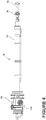
- Figure 4 illustrates an actuator 70 with a cylinder 72 having an actuator housing 74, which may be used in the thrust reverser actuation system 50.
- An end assembly 76 may be provided to facilitate connection to the movable element and is shown in a retracted position and a partially extended position (in phantom).
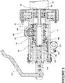
- Figure 5 illustrates a cross section of a portion of the actuator 70.
- a piston 78 is axially movable within the cylinder 72 and is coupled with a lead screw 80.
- the lead screw 80 and piston 78 may be thought of as forming the extendable/retractable portion of the actuator 70.
- One end 82 of the lead screw 80 may be held in suitable bearings 84 within the actuator housing 74.
- the lead screw 80 rotates at a speed proportional to the velocity of the piston 78.
- the end assembly 76 also extends and the moveable element of the thrust reverser is moved.
- Piston 78 is anti-rotated by attachment of the end assembly 76 to the moveable element.
- a synchronization mechanism 90 may be operably coupled to the lead screw 80. More specifically, a worm gear shaft 92 may be coupled with the lead screw 80 through a worm wheel 94 and may form the synchronization mechanism 90 between multiple actuators 70. Each actuator 70 in the thrust reverser actuation system 50 may include similar components and the worm gear shafts 92 of each actuator 70 may be coupled with each other. Because the speed of the worm gear shaft 92 is also proportional to the velocity of the piston 78, when the worm gear shafts 92 of two or more such actuators 70 are connected together, they will be mechanically synchronized.
- the actuator 70 may be locked into position by a lockout mechanism 100.
- the lockout mechanism 100 may selectively couple with the lead screw 80 and may be movable between an inhibit condition ( Figure 7 ) wherein movement of the multiple actuators 70 is prevented, and a permit condition ( Figure 5 ), wherein movement of the multiple actuators 70 is permitted.
- a piston 102 forming a portion of the lockout mechanism 100 may be axially movable within the actuator housing 74 toward and away from the end 82 of the lead screw 80.
- the piston 102 may be moveable between a first position, corresponding to the permit condition of the hydraulic actuator 70 ( Figure 5 ), and a second position where the piston 102 selectively couples with the end 82 of the lead screw 80, corresponding to the inhibit condition of the hydraulic actuator 70 and the synchronization mechanism 90 ( Figure 7 ).
- the piston 102 may be selectively coupled with the lead screw 80 in any suitable manner.
- the piston 102 includes teeth 104 that engage portions of the lead screw 80, such as corresponding teeth 106 on the lead screw 80.
- a handle 110 is operably coupled with the piston 102 and may move the piston 102 between the first position and the second position.
- the handle 110 may be formed in any suitable manner and may be operably coupled with the piston 102 in any suitable manner.
- the handle 110 is operably coupled to the piston 102 through a rotatable link 112.
- the handle 110 is moveable between a first position ( Figure 5 ) where the lockout mechanism 100 is in the permit condition and a second position ( Figure 7 ) where the lockout mechanism 100 is in the inhibit condition.
- When the handle 110 is in the first position it may be pulled by a user to an intermediate position illustrated in Figure 6 .
- the handle 110 may be continued to be pulled until the rotatable link 112 is rotated to an over-center position when the handle 110 is moved to the second position as illustrated in Figure 7 .
- a biasing element 120 may resist the movement of the handle 110 to the second position and may bias the piston 102 away from the lead screw 80.
- the biasing element may include any suitable biasing element including a spring. Once the handle 110 is moved to the second position the biasing element 120 may bias the link 112 to the over-center position. In this manner the biasing element 120 forms a lock element.
- a user may operate the handle 110 to place the lockout mechanism 100 into the inhibit condition.
- the piston 102 operably couples with the lead screw 80 and prevents rotation of the lead screw 80. More specifically, the teeth 104 of the piston 102 engage with the teeth 106 of the lead screw 80 and prevent the lead screw 80 from rotating. As the lead screw 80 is prevented from rotating the worm gear shaft 92 and the other actuators 70 are also inhibited from moving.
- a user may simply push on the handle 110 to overcome the force created by the biasing element 120.
- the biasing element 120 may continue to push the piston 102 away from the lead screw 80 so that the teeth 104 and 106 may disengage and the lock mechanism may be released.
- the actuators 70 may be permitted to move.
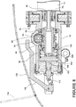
- Figure 8 illustrates a door 130 that is located adjacent the handle 110 and is moveable between a closed position (as shown) and an opened position (in phantom). In the opened position the door 130 may provide access to the handle 110. If the handle 110 is left in the second position, corresponding to the inhibit condition of the lockout mechanism 100, when the door 130 is moved to the closed position, the door 130 contacts the handle 110 with enough force to overcome the biasing element 120 and move the handle 110 back to the first position. This returns the lockout mechanism 100 to the permit condition and allows the lead screw 80 to rotate and the actuator 70 to operate. In this manner, upon closure of the door 130 the lockout mechanism 100 may be automatically unlocked.
- the embodiments described above provide for a variety of benefits including that movement of the movable element of the thrust reverser may be inhibited for crew safety.
- the above described embodiments provide enhanced safety during maintenance with minimum impact on installation and weight.
Landscapes
- Engineering & Computer Science (AREA)
- Chemical & Material Sciences (AREA)
- Combustion & Propulsion (AREA)
- Mechanical Engineering (AREA)
- General Engineering & Computer Science (AREA)
- Retarders (AREA)
- Structures Of Non-Positive Displacement Pumps (AREA)
- Supercharger (AREA)
Description
- Contemporary aircraft engines may include a thrust reverser actuation system to assist in reducing the aircraft speed during landing. Typical thrust reversers include a movable element that when in the active position reverses at least a portion of the air flow passing through the engine. During maintenance of such areas of the engine the movement of the movable part is inhibited for safety; currently, this is done manually by a user near the equipment that controls the hydraulic flow to the movable element.
US 2003/0070416 A1 relates to a jet engine thrust reverser system having torque limited synchronization and discloses features generally corresponding to the preamble of claim 1.EP 0 090 540 A2 relates to a fluid actuator with lock position indicating means.US 4,491,059 relates to a fluid actuator with manual lock release and lock position sensor. - The invention relates to a turbofan engine according to claim 1.
- In the drawings:
-
Figure 1 is a schematic view of a turbofan jet engine with a portion of the outer nacelle cut away for clarity; -
Figure 2 is a schematic view of the engine ofFigure 1 with an exemplary thrust reverser; -
Figure 3 is a schematic view of a thrust reverser actuation system that may be utilized in the turbofan jet engine ofFigure 1 ; -
Figure 4 is a side view of an actuator that may be utilized in the system ofFigure 3 ; -
Figure 5 is a cross-sectional view of a portion of the actuator ofFigure 4 with the lockout mechanism in a permit condition; -
Figure 6 is a cross-sectional view of a portion of the actuator ofFigure 4 with a lockout mechanism in an intermediate position; -
Figure 7 is a cross-sectional view of a portion of the actuator ofFigure 4 with the lockout mechanism in an inhibit condition; and -
Figure 8 is a cross-sectional view of a portion of the actuator ofFigure 4 and schematically illustrating positions of an engine service door. -
Figure 1 illustrates a turbofanjet engine assembly 10 having aturbine engine 12, afan assembly 13, and anacelle 14. Portions of thenacelle 14 have been cut away for clarity. Thenacelle 14 surrounds theturbine engine 12 and defines an annular air flow path orannular bypass duct 16 through thejet engine assembly 10 to define a generally forward-to-aft bypass air flow path as schematically illustrated by thearrow 18. - A thrust reverser with at least one movable element, which is movable to and from a reversing position, may be used to change the direction of the bypass airflow. In the reversing position the movable element may be configured to reverse at least a portion of the bypass air flow. There are several methods of obtaining reverse thrust on turbofan jet engine assemblies.
Figure 2 schematically illustrates one example of athrust reverser 20 that may be used in the turbofanjet engine assembly 10. Thethrust reverser 20 includes at least one moveable control surface ormovable element 22. Themovable element 22 has been illustrated as a slidable portion of an outer cowling that is capable of axial motion with respect to the forward portion of thenacelle 14. Ahydraulic actuator 24 may be coupled to themovable element 22 to move themovable element 22 into and out of the reversing position. In the reversing position, as illustrated, themovable element 22 limits the annular bypass area between themovable element 22 and theturbine engine 12, it also opens up aportion 26 between themovable element 22 and the forward portion of thenacelle 14 such that the air flow path may be reversed as illustrated by thearrows 28. An optional deflector or flap may be included to aid in directing the air flow path between themovable element 22 and the forward portion of thenacelle 14. - The thrust reverser 20 changes the direction of the thrust force by reversing at least a portion of the bypass air flow. It will be understood that any number of multiple actuators may be utilized to move the moveable element into the reversing position.
Figure 3 schematically illustrates a thrustreverser actuation system 50 that may be used in the turbofanjet engine assembly 10 and that includesmultiple actuators 52 with eachactuator 52 having an extendable/retractable portion 54 that may be operably coupled to themoveable element 56 to move the movable element into and out of the reversing position. Themultiple actuators 52 may be fluidly connected with ahydraulic supply line 58 andreturn line 60. Asynchronization mechanism 62 may be included to synchronize themultiple actuators 52. It will be understood that any number ofmultiple actuators 52 may be included in the thrustreverser actuation system 50 and that while fouractuators 52 have been illustrated, that the thrustreverser actuation system 50 may include as few as twoactuators 52. -
Figure 4 illustrates anactuator 70 with acylinder 72 having anactuator housing 74, which may be used in the thrustreverser actuation system 50. Anend assembly 76 may be provided to facilitate connection to the movable element and is shown in a retracted position and a partially extended position (in phantom).Figure 5 illustrates a cross section of a portion of theactuator 70. Apiston 78 is axially movable within thecylinder 72 and is coupled with alead screw 80. Thelead screw 80 andpiston 78 may be thought of as forming the extendable/retractable portion of theactuator 70. Oneend 82 of thelead screw 80 may be held insuitable bearings 84 within theactuator housing 74. As thepiston 78 moves back and forth in thecylinder 72, thelead screw 80 rotates at a speed proportional to the velocity of thepiston 78. As thepiston 78 extends theend assembly 76 also extends and the moveable element of the thrust reverser is moved. Piston 78 is anti-rotated by attachment of theend assembly 76 to the moveable element. - A
synchronization mechanism 90 may be operably coupled to thelead screw 80. More specifically, aworm gear shaft 92 may be coupled with thelead screw 80 through aworm wheel 94 and may form thesynchronization mechanism 90 betweenmultiple actuators 70. Eachactuator 70 in the thrustreverser actuation system 50 may include similar components and theworm gear shafts 92 of eachactuator 70 may be coupled with each other. Because the speed of theworm gear shaft 92 is also proportional to the velocity of thepiston 78, when theworm gear shafts 92 of two or moresuch actuators 70 are connected together, they will be mechanically synchronized. - The
actuator 70 may be locked into position by alockout mechanism 100. Thelockout mechanism 100 may selectively couple with thelead screw 80 and may be movable between an inhibit condition (Figure 7 ) wherein movement of themultiple actuators 70 is prevented, and a permit condition (Figure 5 ), wherein movement of themultiple actuators 70 is permitted. Apiston 102 forming a portion of thelockout mechanism 100 may be axially movable within theactuator housing 74 toward and away from theend 82 of thelead screw 80. Thepiston 102 may be moveable between a first position, corresponding to the permit condition of the hydraulic actuator 70 (Figure 5 ), and a second position where thepiston 102 selectively couples with theend 82 of thelead screw 80, corresponding to the inhibit condition of thehydraulic actuator 70 and the synchronization mechanism 90 (Figure 7 ). Thepiston 102 may be selectively coupled with thelead screw 80 in any suitable manner. In the illustrated example, thepiston 102 includesteeth 104 that engage portions of thelead screw 80, such ascorresponding teeth 106 on thelead screw 80. - A
handle 110 is operably coupled with thepiston 102 and may move thepiston 102 between the first position and the second position. Thehandle 110 may be formed in any suitable manner and may be operably coupled with thepiston 102 in any suitable manner. In the illustrated example, thehandle 110 is operably coupled to thepiston 102 through arotatable link 112. Thehandle 110 is moveable between a first position (Figure 5 ) where thelockout mechanism 100 is in the permit condition and a second position (Figure 7 ) where thelockout mechanism 100 is in the inhibit condition. When thehandle 110 is in the first position it may be pulled by a user to an intermediate position illustrated inFigure 6 . Thehandle 110 may be continued to be pulled until therotatable link 112 is rotated to an over-center position when thehandle 110 is moved to the second position as illustrated inFigure 7 . - A
biasing element 120 may resist the movement of thehandle 110 to the second position and may bias thepiston 102 away from thelead screw 80. The biasing element may include any suitable biasing element including a spring. Once thehandle 110 is moved to the second position the biasingelement 120 may bias thelink 112 to the over-center position. In this manner the biasingelement 120 forms a lock element. - When it is desired to inhibit the movement of the moveable element of the thrust reverser a user may operate the
handle 110 to place thelockout mechanism 100 into the inhibit condition. When thelockout mechanism 100 is in the inhibit condition, thepiston 102 operably couples with thelead screw 80 and prevents rotation of thelead screw 80. More specifically, theteeth 104 of thepiston 102 engage with theteeth 106 of thelead screw 80 and prevent thelead screw 80 from rotating. As thelead screw 80 is prevented from rotating theworm gear shaft 92 and theother actuators 70 are also inhibited from moving. - In this manner, when the lockout mechanism is in the inhibit condition movement of the
multiple actuators 70 is prevented through thesynchronization mechanism 90. Because theworm gear shaft 92 is coupled with thelead screw 80 and because theworm gear shafts 92 of two or moresuch actuators 70 are connected together thelockout mechanism 100 may prevent motion of theother actuators 70. In this manner thelockout mechanism 100 locks out each of the multiple actuators operably coupled to the synchronization mechanism. - To disengage the lockout mechanism 100 a user may simply push on the
handle 110 to overcome the force created by the biasingelement 120. The biasingelement 120 may continue to push thepiston 102 away from thelead screw 80 so that theteeth lockout mechanism 100 is put into a permit condition, theactuators 70 may be permitted to move. -
Figure 8 illustrates adoor 130 that is located adjacent thehandle 110 and is moveable between a closed position (as shown) and an opened position (in phantom). In the opened position thedoor 130 may provide access to thehandle 110. If thehandle 110 is left in the second position, corresponding to the inhibit condition of thelockout mechanism 100, when thedoor 130 is moved to the closed position, thedoor 130 contacts thehandle 110 with enough force to overcome the biasingelement 120 and move thehandle 110 back to the first position. This returns thelockout mechanism 100 to the permit condition and allows thelead screw 80 to rotate and theactuator 70 to operate. In this manner, upon closure of thedoor 130 thelockout mechanism 100 may be automatically unlocked. - The embodiments described above provide for a variety of benefits including that movement of the movable element of the thrust reverser may be inhibited for crew safety. The above described embodiments provide enhanced safety during maintenance with minimum impact on installation and weight.
- This written description uses examples to disclose the invention, including the best mode, and also to enable any person skilled in the art to practice the invention, including making and using any devices or systems and performing any incorporated methods. The patentable scope of the invention is defined by the claims.
Claims (7)
- A turbofan engine (10) comprising:a turbine engine (12);a nacelle (14) surrounding the turbine engine and defining an annular bypass duct (16) between the nacelle and the turbine engine and extending through the turbofan engine to define a generally forward-to-aft bypass air flow path (18);a thrust reverser (20) having at least one movable control surface (22), movable to and from a reversing position where at least a portion of the bypass air flow is at least partially reversed (28);a thrust reverser actuation system (50) having multiple actuators (70) with each actuator having a piston (78) being axially movable within a cylinder (72) of the actuator and being operably coupled to the at least one movable control surface to move the at least one movable control surface into and out of the reversing position, a lead screw (80) rotating at a speed proportional to the velocity of the piston when in use, and a synchronization mechanism (90) to synchronize the multiple actuators; anda lockout mechanism (100);characterized in that:the lockout mechanism (100) is selectively coupled to the lead screw (80) of one of the multiple actuators and movable between an inhibit condition, wherein movement of the multiple actuators is prevented, and a permit condition, wherein movement of the multiple actuators is permitted;the lockout mechanism further comprises a handle (110) for moving the lockout mechanism between the inhibit condition and the permit condition;the turbofan engine further comprises a door (130) located adjacent the handle and moveable between a closed position and an opened position wherein access to the handle is provided;wherein when the door is moved to the closed position it contacts the handle to move the lockout mechanism to the permit condition;wherein the lockout mechanism (100) further comprises a piston (102) axially moveable between a first position and a second position where the piston selectively couples with the lead screw (80);wherein the handle (110) is operably coupled to the piston (102) of the lockout mechanism and the handle is moveable between a first position where the lockout mechanism (100) is in the permit condition and a second position where the lockout mechanism is in the inhibit condition;wherein when the lockout mechanism (100) is in the inhibit condition, the piston (102) of the lockout mechanism operably couples with the lead screw (80) and prevents rotation of the lead screw;wherein the piston (102) of the lockout mechanism comprises teeth (104) that engage portions of the lead screw (80) and prevent rotation of the lead screw when the piston is in the second position that corresponds to the inhibit condition.
- The turbofan engine (10) of claim 1, wherein the lockout mechanism (100) further comprises a biasing element (120) to resist movement of the handle (110) to the second position.
- The turbofan engine (10) of claim 2, wherein the handle (110) is operably coupled to the piston (102) of the lockout mechanism through a rotatable link (112).
- The turbofan engine (10) of claim 3, wherein the link (112) is rotatable to an over-center position when the handle (110) is moved to the second position.
- The turbofan engine of claim 4, wherein the lockout mechanism (100) further comprises a biasing element (120) to bias the piston (102) of the lockout mechanism to the over-center position.
- The turbofan engine (10) of claim 1, wherein the synchronization mechanism (90) is operably coupled to the lead screw (80).
- The turbofan engine (10) of claim 1, wherein the lockout mechanism (100) locks out each of the multiple actuators (70) operably coupled to the synchronization mechanism (90).
Applications Claiming Priority (1)
| Application Number | Priority Date | Filing Date | Title |
|---|---|---|---|
| PCT/US2013/044730 WO2014196985A1 (en) | 2013-06-07 | 2013-06-07 | Engine with a thrust reverser lockout mechanism |
Publications (3)
| Publication Number | Publication Date |
|---|---|
| EP3004593A1 EP3004593A1 (en) | 2016-04-13 |
| EP3004593A4 EP3004593A4 (en) | 2017-02-15 |
| EP3004593B1 true EP3004593B1 (en) | 2021-01-13 |
Family
ID=52008467
Family Applications (1)
| Application Number | Title | Priority Date | Filing Date |
|---|---|---|---|
| EP13886258.6A Active EP3004593B1 (en) | 2013-06-07 | 2013-06-07 | Engine with a thrust reverser lockout mechanism |
Country Status (7)
| Country | Link |
|---|---|
| US (1) | US10344710B2 (en) |
| EP (1) | EP3004593B1 (en) |
| JP (1) | JP6110994B2 (en) |
| CN (1) | CN205638706U (en) |
| BR (1) | BR112015028961A2 (en) |
| CA (1) | CA2913527C (en) |
| WO (1) | WO2014196985A1 (en) |
Families Citing this family (3)
| Publication number | Priority date | Publication date | Assignee | Title |
|---|---|---|---|---|
| US11441514B2 (en) | 2018-10-02 | 2022-09-13 | Woodward, Inc. | Tertiary lock |
| US10865738B2 (en) | 2019-02-27 | 2020-12-15 | Woodward, Inc. | Traveling finger lock for an actuator |
| US11788490B1 (en) * | 2022-12-05 | 2023-10-17 | Woodward, Inc. | Traveling finger lock for an actuator |
Citations (1)
| Publication number | Priority date | Publication date | Assignee | Title |
|---|---|---|---|---|
| US4491059A (en) * | 1982-03-29 | 1985-01-01 | Pneumo Corporation | Fluid actuator with manual lock release and lock position sensor |
Family Cites Families (27)
| Publication number | Priority date | Publication date | Assignee | Title |
|---|---|---|---|---|
| US2688232A (en) * | 1953-06-22 | 1954-09-07 | Gen Motors Corp | Synchronized locking actuator |
| US3180234A (en) * | 1963-07-25 | 1965-04-27 | Jarry Hydraulics Ltd | Dual-position lockable actuator |
| US4714006A (en) * | 1982-02-24 | 1987-12-22 | Pneumo Corporation | Fluid actuator with feedback mechanism |
| US4463661A (en) * | 1982-02-24 | 1984-08-07 | Pneumo Corporation | Fluid actuator with remote lock release assembly |
| US4754694A (en) * | 1982-03-29 | 1988-07-05 | Pneumo Abex Corporation | Fluid actuator with lock position indicating means |
| EP0536954B1 (en) | 1991-10-10 | 1996-01-24 | Lucas Industries Public Limited Company | A lock for a thrust reverser mechanism, a thrust reverser mechanism, and a thrust reverser |
| US5609020A (en) * | 1995-05-15 | 1997-03-11 | The Boeing Company | Thrust reverser synchronization shaft lock |
| EP0763654B1 (en) * | 1995-09-13 | 1999-12-29 | SOCIETE DE CONSTRUCTION DES AVIONS HUREL-DUBOIS (société anonyme) | Electro/hydraulic system for a 2 door thrust reverser |
| EP0801221A3 (en) | 1996-04-09 | 1998-11-04 | Lucas Industries Public Limited Company | Actuating system for an aircraft thrust reverser |
| FR2755730B1 (en) | 1996-11-14 | 1999-01-08 | Hispano Suiza Sa | ELECTRICAL CONTROL SYSTEM FOR A TURBOREACTOR DRIVE INVERTER |
| FR2765916B1 (en) * | 1997-07-10 | 1999-08-20 | Hispano Suiza Sa | PUSH INVERTER WITH IMPROVED IMPACT RESISTANCE |
| US6042053A (en) * | 1997-10-31 | 2000-03-28 | The Boeing Company | Automatic restow system for aircraft thrust reverser |
| US6220546B1 (en) * | 1999-12-29 | 2001-04-24 | The Boeing Company | Aircraft engine and associated aircraft engine cowl |
| US6625972B1 (en) * | 2001-08-30 | 2003-09-30 | The Boeing Company | Thrust reverser sleeve lock |
| US6554224B2 (en) * | 2001-08-31 | 2003-04-29 | The Boeing Company | Out-of-plane thrust reverser sleeve lock |
| US6487846B1 (en) * | 2001-09-07 | 2002-12-03 | Honeywell International, Inc. | Thrust reverser actuator including an integrated locking mechanism |
| US6786039B2 (en) * | 2001-09-07 | 2004-09-07 | Honeywell International, Inc. | Thrust reverser actuator with an automatic relock and lock drop prevention mechanism |
| US6598386B2 (en) | 2001-10-16 | 2003-07-29 | Honeywell International, Inc. | Jet engine thrust reverser system having torque limited synchronization |
| FR2846376B1 (en) | 2002-10-25 | 2005-01-28 | Hispano Suiza Sa | MAINTENANCE AND INHIBITION PLATINUM FOR THRUST INVERTER |
| US20050001095A1 (en) * | 2003-05-05 | 2005-01-06 | Christensen Donald J. | Self-aligning thrust reverser system lock assembly |
| US7216581B2 (en) * | 2004-01-16 | 2007-05-15 | The Boeing Company | Piston locking actuator |
| US7946105B2 (en) * | 2006-11-02 | 2011-05-24 | Honeywell International Inc. | Bi-directional locking ring assembly for aircraft thrust reverser manual drive unit |
| US20080134664A1 (en) * | 2006-12-06 | 2008-06-12 | Spirit Aerosystems, Inc. | Thrust reverser pin lock |
| FR2917788B1 (en) | 2007-06-19 | 2009-07-24 | Aircelle Sa | DOUBLE ACTION ACTUATOR WITH PROGRAM EFFECT |
| US8978356B2 (en) * | 2010-12-03 | 2015-03-17 | The Boeing Company | Thrust reverser and variable area fan nozzle actuation system and method |
| US8713911B2 (en) * | 2010-12-15 | 2014-05-06 | Woodward Hrt, Inc. | System and method for operating a thrust reverser for a turbofan propulsion system |
| US9188081B2 (en) * | 2012-04-10 | 2015-11-17 | Honeywell International Inc. | Thrust reverser actuator with primary lock |
-
2013
- 2013-06-07 WO PCT/US2013/044730 patent/WO2014196985A1/en not_active Ceased
- 2013-06-07 JP JP2016518309A patent/JP6110994B2/en active Active
- 2013-06-07 US US14/888,811 patent/US10344710B2/en active Active
- 2013-06-07 CA CA2913527A patent/CA2913527C/en active Active
- 2013-06-07 BR BR112015028961A patent/BR112015028961A2/en not_active Application Discontinuation
- 2013-06-07 EP EP13886258.6A patent/EP3004593B1/en active Active
- 2013-06-07 CN CN201390001207.XU patent/CN205638706U/en not_active Expired - Lifetime
Patent Citations (1)
| Publication number | Priority date | Publication date | Assignee | Title |
|---|---|---|---|---|
| US4491059A (en) * | 1982-03-29 | 1985-01-01 | Pneumo Corporation | Fluid actuator with manual lock release and lock position sensor |
Also Published As
| Publication number | Publication date |
|---|---|
| CA2913527A1 (en) | 2014-12-11 |
| EP3004593A1 (en) | 2016-04-13 |
| WO2014196985A1 (en) | 2014-12-11 |
| JP2016523335A (en) | 2016-08-08 |
| US10344710B2 (en) | 2019-07-09 |
| US20160076486A1 (en) | 2016-03-17 |
| JP6110994B2 (en) | 2017-04-05 |
| CN205638706U (en) | 2016-10-12 |
| EP3004593A4 (en) | 2017-02-15 |
| BR112015028961A2 (en) | 2017-07-25 |
| CA2913527C (en) | 2018-01-09 |
Similar Documents
| Publication | Publication Date | Title |
|---|---|---|
| EP1554484B1 (en) | Thrust reverser actuator with an automatic relock and lock drop prevention mechanism | |
| EP2466101B1 (en) | System and method for operating a thrust reverser for a turbofan propulsion system | |
| EP2650519B1 (en) | Thrust reverser actuator with primary lock | |
| US8615982B2 (en) | Integrated electric variable area fan nozzle thrust reversal actuation system | |
| EP1918562B1 (en) | Bi-directional locking ring assembly for aircraft thrust reverser manual drive unit | |
| CN105723079B (en) | Actuator apparatus for moving a movable cowl of a thrust reverser | |
| US9562595B2 (en) | Double-acting linear actuator | |
| US9909531B2 (en) | Engine and thrust reverser actuation system | |
| EP3931434B1 (en) | Traveling finger lock for an actuator | |
| US9458795B2 (en) | Actuation device for moving a movable cover of a thrust reverser | |
| US20220372930A1 (en) | Tertiary lock | |
| EP2602464A2 (en) | Common control for thrust reverser and variable area fan nozzle | |
| EP4176169B1 (en) | Hydraulic baulking sync lock | |
| CA2913527C (en) | Engine with a thrust reverser lockout mechanism | |
| EP2574765A2 (en) | Variable area fan nozzle with locking assembly | |
| CN104838125B (en) | Actuation means including main locking system | |
| WO2015065428A1 (en) | Thrust reverser system and engine assembly with lockout mechanism |
Legal Events
| Date | Code | Title | Description |
|---|---|---|---|
| PUAI | Public reference made under article 153(3) epc to a published international application that has entered the european phase |
Free format text: ORIGINAL CODE: 0009012 |
|
| 17P | Request for examination filed |
Effective date: 20160107 |
|
| AK | Designated contracting states |
Kind code of ref document: A1 Designated state(s): AL AT BE BG CH CY CZ DE DK EE ES FI FR GB GR HR HU IE IS IT LI LT LU LV MC MK MT NL NO PL PT RO RS SE SI SK SM TR |
|
| AX | Request for extension of the european patent |
Extension state: BA ME |
|
| DAX | Request for extension of the european patent (deleted) | ||
| REG | Reference to a national code |
Ref country code: DE Ref legal event code: R079 Ref document number: 602013075337 Country of ref document: DE Free format text: PREVIOUS MAIN CLASS: F02C0007000000 Ipc: F02K0001720000 |
|
| A4 | Supplementary search report drawn up and despatched |
Effective date: 20170117 |
|
| RIC1 | Information provided on ipc code assigned before grant |
Ipc: F02K 1/72 20060101AFI20170111BHEP Ipc: F02K 1/76 20060101ALI20170111BHEP |
|
| STAA | Information on the status of an ep patent application or granted ep patent |
Free format text: STATUS: EXAMINATION IS IN PROGRESS |
|
| 17Q | First examination report despatched |
Effective date: 20171207 |
|
| GRAP | Despatch of communication of intention to grant a patent |
Free format text: ORIGINAL CODE: EPIDOSNIGR1 |
|
| STAA | Information on the status of an ep patent application or granted ep patent |
Free format text: STATUS: GRANT OF PATENT IS INTENDED |
|
| INTG | Intention to grant announced |
Effective date: 20200811 |
|
| GRAS | Grant fee paid |
Free format text: ORIGINAL CODE: EPIDOSNIGR3 |
|
| GRAA | (expected) grant |
Free format text: ORIGINAL CODE: 0009210 |
|
| STAA | Information on the status of an ep patent application or granted ep patent |
Free format text: STATUS: THE PATENT HAS BEEN GRANTED |
|
| AK | Designated contracting states |
Kind code of ref document: B1 Designated state(s): AL AT BE BG CH CY CZ DE DK EE ES FI FR GB GR HR HU IE IS IT LI LT LU LV MC MK MT NL NO PL PT RO RS SE SI SK SM TR |
|
| REG | Reference to a national code |
Ref country code: GB Ref legal event code: FG4D |
|
| REG | Reference to a national code |
Ref country code: CH Ref legal event code: EP |
|
| REG | Reference to a national code |
Ref country code: IE Ref legal event code: FG4D |
|
| REG | Reference to a national code |
Ref country code: DE Ref legal event code: R096 Ref document number: 602013075337 Country of ref document: DE |
|
| REG | Reference to a national code |
Ref country code: AT Ref legal event code: REF Ref document number: 1354737 Country of ref document: AT Kind code of ref document: T Effective date: 20210215 |
|
| REG | Reference to a national code |
Ref country code: AT Ref legal event code: MK05 Ref document number: 1354737 Country of ref document: AT Kind code of ref document: T Effective date: 20210113 |
|
| REG | Reference to a national code |
Ref country code: NL Ref legal event code: MP Effective date: 20210113 |
|
| REG | Reference to a national code |
Ref country code: LT Ref legal event code: MG9D |
|
| PG25 | Lapsed in a contracting state [announced via postgrant information from national office to epo] |
Ref country code: LT Free format text: LAPSE BECAUSE OF FAILURE TO SUBMIT A TRANSLATION OF THE DESCRIPTION OR TO PAY THE FEE WITHIN THE PRESCRIBED TIME-LIMIT Effective date: 20210113 Ref country code: PT Free format text: LAPSE BECAUSE OF FAILURE TO SUBMIT A TRANSLATION OF THE DESCRIPTION OR TO PAY THE FEE WITHIN THE PRESCRIBED TIME-LIMIT Effective date: 20210513 Ref country code: HR Free format text: LAPSE BECAUSE OF FAILURE TO SUBMIT A TRANSLATION OF THE DESCRIPTION OR TO PAY THE FEE WITHIN THE PRESCRIBED TIME-LIMIT Effective date: 20210113 Ref country code: GR Free format text: LAPSE BECAUSE OF FAILURE TO SUBMIT A TRANSLATION OF THE DESCRIPTION OR TO PAY THE FEE WITHIN THE PRESCRIBED TIME-LIMIT Effective date: 20210414 Ref country code: FI Free format text: LAPSE BECAUSE OF FAILURE TO SUBMIT A TRANSLATION OF THE DESCRIPTION OR TO PAY THE FEE WITHIN THE PRESCRIBED TIME-LIMIT Effective date: 20210113 Ref country code: BG Free format text: LAPSE BECAUSE OF FAILURE TO SUBMIT A TRANSLATION OF THE DESCRIPTION OR TO PAY THE FEE WITHIN THE PRESCRIBED TIME-LIMIT Effective date: 20210413 Ref country code: NO Free format text: LAPSE BECAUSE OF FAILURE TO SUBMIT A TRANSLATION OF THE DESCRIPTION OR TO PAY THE FEE WITHIN THE PRESCRIBED TIME-LIMIT Effective date: 20210413 Ref country code: NL Free format text: LAPSE BECAUSE OF FAILURE TO SUBMIT A TRANSLATION OF THE DESCRIPTION OR TO PAY THE FEE WITHIN THE PRESCRIBED TIME-LIMIT Effective date: 20210113 |
|
| PG25 | Lapsed in a contracting state [announced via postgrant information from national office to epo] |
Ref country code: SE Free format text: LAPSE BECAUSE OF FAILURE TO SUBMIT A TRANSLATION OF THE DESCRIPTION OR TO PAY THE FEE WITHIN THE PRESCRIBED TIME-LIMIT Effective date: 20210113 Ref country code: AT Free format text: LAPSE BECAUSE OF FAILURE TO SUBMIT A TRANSLATION OF THE DESCRIPTION OR TO PAY THE FEE WITHIN THE PRESCRIBED TIME-LIMIT Effective date: 20210113 Ref country code: PL Free format text: LAPSE BECAUSE OF FAILURE TO SUBMIT A TRANSLATION OF THE DESCRIPTION OR TO PAY THE FEE WITHIN THE PRESCRIBED TIME-LIMIT Effective date: 20210113 Ref country code: RS Free format text: LAPSE BECAUSE OF FAILURE TO SUBMIT A TRANSLATION OF THE DESCRIPTION OR TO PAY THE FEE WITHIN THE PRESCRIBED TIME-LIMIT Effective date: 20210113 Ref country code: LV Free format text: LAPSE BECAUSE OF FAILURE TO SUBMIT A TRANSLATION OF THE DESCRIPTION OR TO PAY THE FEE WITHIN THE PRESCRIBED TIME-LIMIT Effective date: 20210113 |
|
| PG25 | Lapsed in a contracting state [announced via postgrant information from national office to epo] |
Ref country code: IS Free format text: LAPSE BECAUSE OF FAILURE TO SUBMIT A TRANSLATION OF THE DESCRIPTION OR TO PAY THE FEE WITHIN THE PRESCRIBED TIME-LIMIT Effective date: 20210513 |
|
| REG | Reference to a national code |
Ref country code: DE Ref legal event code: R097 Ref document number: 602013075337 Country of ref document: DE |
|
| PG25 | Lapsed in a contracting state [announced via postgrant information from national office to epo] |
Ref country code: CZ Free format text: LAPSE BECAUSE OF FAILURE TO SUBMIT A TRANSLATION OF THE DESCRIPTION OR TO PAY THE FEE WITHIN THE PRESCRIBED TIME-LIMIT Effective date: 20210113 Ref country code: EE Free format text: LAPSE BECAUSE OF FAILURE TO SUBMIT A TRANSLATION OF THE DESCRIPTION OR TO PAY THE FEE WITHIN THE PRESCRIBED TIME-LIMIT Effective date: 20210113 Ref country code: SM Free format text: LAPSE BECAUSE OF FAILURE TO SUBMIT A TRANSLATION OF THE DESCRIPTION OR TO PAY THE FEE WITHIN THE PRESCRIBED TIME-LIMIT Effective date: 20210113 |
|
| PLBE | No opposition filed within time limit |
Free format text: ORIGINAL CODE: 0009261 |
|
| STAA | Information on the status of an ep patent application or granted ep patent |
Free format text: STATUS: NO OPPOSITION FILED WITHIN TIME LIMIT |
|
| PG25 | Lapsed in a contracting state [announced via postgrant information from national office to epo] |
Ref country code: ES Free format text: LAPSE BECAUSE OF FAILURE TO SUBMIT A TRANSLATION OF THE DESCRIPTION OR TO PAY THE FEE WITHIN THE PRESCRIBED TIME-LIMIT Effective date: 20210113 Ref country code: DK Free format text: LAPSE BECAUSE OF FAILURE TO SUBMIT A TRANSLATION OF THE DESCRIPTION OR TO PAY THE FEE WITHIN THE PRESCRIBED TIME-LIMIT Effective date: 20210113 Ref country code: SK Free format text: LAPSE BECAUSE OF FAILURE TO SUBMIT A TRANSLATION OF THE DESCRIPTION OR TO PAY THE FEE WITHIN THE PRESCRIBED TIME-LIMIT Effective date: 20210113 Ref country code: RO Free format text: LAPSE BECAUSE OF FAILURE TO SUBMIT A TRANSLATION OF THE DESCRIPTION OR TO PAY THE FEE WITHIN THE PRESCRIBED TIME-LIMIT Effective date: 20210113 |
|
| 26N | No opposition filed |
Effective date: 20211014 |
|
| REG | Reference to a national code |
Ref country code: DE Ref legal event code: R119 Ref document number: 602013075337 Country of ref document: DE |
|
| PG25 | Lapsed in a contracting state [announced via postgrant information from national office to epo] |
Ref country code: AL Free format text: LAPSE BECAUSE OF FAILURE TO SUBMIT A TRANSLATION OF THE DESCRIPTION OR TO PAY THE FEE WITHIN THE PRESCRIBED TIME-LIMIT Effective date: 20210113 Ref country code: MC Free format text: LAPSE BECAUSE OF FAILURE TO SUBMIT A TRANSLATION OF THE DESCRIPTION OR TO PAY THE FEE WITHIN THE PRESCRIBED TIME-LIMIT Effective date: 20210113 |
|
| REG | Reference to a national code |
Ref country code: CH Ref legal event code: PL |
|
| GBPC | Gb: european patent ceased through non-payment of renewal fee |
Effective date: 20210607 |
|
| PG25 | Lapsed in a contracting state [announced via postgrant information from national office to epo] |
Ref country code: SI Free format text: LAPSE BECAUSE OF FAILURE TO SUBMIT A TRANSLATION OF THE DESCRIPTION OR TO PAY THE FEE WITHIN THE PRESCRIBED TIME-LIMIT Effective date: 20210113 |
|
| REG | Reference to a national code |
Ref country code: BE Ref legal event code: MM Effective date: 20210630 |
|
| PG25 | Lapsed in a contracting state [announced via postgrant information from national office to epo] |
Ref country code: LU Free format text: LAPSE BECAUSE OF NON-PAYMENT OF DUE FEES Effective date: 20210607 |
|
| PG25 | Lapsed in a contracting state [announced via postgrant information from national office to epo] |
Ref country code: LI Free format text: LAPSE BECAUSE OF NON-PAYMENT OF DUE FEES Effective date: 20210630 Ref country code: IT Free format text: LAPSE BECAUSE OF FAILURE TO SUBMIT A TRANSLATION OF THE DESCRIPTION OR TO PAY THE FEE WITHIN THE PRESCRIBED TIME-LIMIT Effective date: 20210113 Ref country code: IE Free format text: LAPSE BECAUSE OF NON-PAYMENT OF DUE FEES Effective date: 20210607 Ref country code: GB Free format text: LAPSE BECAUSE OF NON-PAYMENT OF DUE FEES Effective date: 20210607 Ref country code: DE Free format text: LAPSE BECAUSE OF NON-PAYMENT OF DUE FEES Effective date: 20220101 Ref country code: CH Free format text: LAPSE BECAUSE OF NON-PAYMENT OF DUE FEES Effective date: 20210630 |
|
| PG25 | Lapsed in a contracting state [announced via postgrant information from national office to epo] |
Ref country code: IS Free format text: LAPSE BECAUSE OF FAILURE TO SUBMIT A TRANSLATION OF THE DESCRIPTION OR TO PAY THE FEE WITHIN THE PRESCRIBED TIME-LIMIT Effective date: 20210513 |
|
| PG25 | Lapsed in a contracting state [announced via postgrant information from national office to epo] |
Ref country code: BE Free format text: LAPSE BECAUSE OF NON-PAYMENT OF DUE FEES Effective date: 20210630 |
|
| PG25 | Lapsed in a contracting state [announced via postgrant information from national office to epo] |
Ref country code: HU Free format text: LAPSE BECAUSE OF FAILURE TO SUBMIT A TRANSLATION OF THE DESCRIPTION OR TO PAY THE FEE WITHIN THE PRESCRIBED TIME-LIMIT; INVALID AB INITIO Effective date: 20130607 |
|
| PG25 | Lapsed in a contracting state [announced via postgrant information from national office to epo] |
Ref country code: CY Free format text: LAPSE BECAUSE OF FAILURE TO SUBMIT A TRANSLATION OF THE DESCRIPTION OR TO PAY THE FEE WITHIN THE PRESCRIBED TIME-LIMIT Effective date: 20210113 |
|
| PG25 | Lapsed in a contracting state [announced via postgrant information from national office to epo] |
Ref country code: MK Free format text: LAPSE BECAUSE OF FAILURE TO SUBMIT A TRANSLATION OF THE DESCRIPTION OR TO PAY THE FEE WITHIN THE PRESCRIBED TIME-LIMIT Effective date: 20210113 |
|
| PG25 | Lapsed in a contracting state [announced via postgrant information from national office to epo] |
Ref country code: TR Free format text: LAPSE BECAUSE OF FAILURE TO SUBMIT A TRANSLATION OF THE DESCRIPTION OR TO PAY THE FEE WITHIN THE PRESCRIBED TIME-LIMIT Effective date: 20210113 |
|
| PG25 | Lapsed in a contracting state [announced via postgrant information from national office to epo] |
Ref country code: MT Free format text: LAPSE BECAUSE OF FAILURE TO SUBMIT A TRANSLATION OF THE DESCRIPTION OR TO PAY THE FEE WITHIN THE PRESCRIBED TIME-LIMIT Effective date: 20210113 |
|
| PGFP | Annual fee paid to national office [announced via postgrant information from national office to epo] |
Ref country code: FR Payment date: 20250520 Year of fee payment: 13 |