EP3003698B1 - Tire building drum with increased range of movement - Google Patents
Tire building drum with increased range of movement Download PDFInfo
- Publication number
- EP3003698B1 EP3003698B1 EP14808335.5A EP14808335A EP3003698B1 EP 3003698 B1 EP3003698 B1 EP 3003698B1 EP 14808335 A EP14808335 A EP 14808335A EP 3003698 B1 EP3003698 B1 EP 3003698B1
- Authority
- EP
- European Patent Office
- Prior art keywords
- actuator
- drum
- tire building
- thrust plate
- along
- Prior art date
- Legal status (The legal status is an assumption and is not a legal conclusion. Google has not performed a legal analysis and makes no representation as to the accuracy of the status listed.)
- Active
Links
Images






Classifications
-
- B—PERFORMING OPERATIONS; TRANSPORTING
- B29—WORKING OF PLASTICS; WORKING OF SUBSTANCES IN A PLASTIC STATE IN GENERAL
- B29D—PRODUCING PARTICULAR ARTICLES FROM PLASTICS OR FROM SUBSTANCES IN A PLASTIC STATE
- B29D30/00—Producing pneumatic or solid tyres or parts thereof
- B29D30/06—Pneumatic tyres or parts thereof (e.g. produced by casting, moulding, compression moulding, injection moulding, centrifugal casting)
- B29D30/08—Building tyres
- B29D30/20—Building tyres by the flat-tyre method, i.e. building on cylindrical drums
- B29D30/24—Drums
- B29D30/242—Drums for manufacturing substantially cylindrical tyre components without cores or beads, e.g. treads or belts
-
- B—PERFORMING OPERATIONS; TRANSPORTING
- B29—WORKING OF PLASTICS; WORKING OF SUBSTANCES IN A PLASTIC STATE IN GENERAL
- B29D—PRODUCING PARTICULAR ARTICLES FROM PLASTICS OR FROM SUBSTANCES IN A PLASTIC STATE
- B29D30/00—Producing pneumatic or solid tyres or parts thereof
- B29D30/06—Pneumatic tyres or parts thereof (e.g. produced by casting, moulding, compression moulding, injection moulding, centrifugal casting)
- B29D30/08—Building tyres
- B29D30/20—Building tyres by the flat-tyre method, i.e. building on cylindrical drums
- B29D30/24—Drums
-
- B—PERFORMING OPERATIONS; TRANSPORTING
- B29—WORKING OF PLASTICS; WORKING OF SUBSTANCES IN A PLASTIC STATE IN GENERAL
- B29D—PRODUCING PARTICULAR ARTICLES FROM PLASTICS OR FROM SUBSTANCES IN A PLASTIC STATE
- B29D30/00—Producing pneumatic or solid tyres or parts thereof
- B29D30/06—Pneumatic tyres or parts thereof (e.g. produced by casting, moulding, compression moulding, injection moulding, centrifugal casting)
- B29D30/08—Building tyres
- B29D30/20—Building tyres by the flat-tyre method, i.e. building on cylindrical drums
- B29D30/24—Drums
- B29D30/244—Drums for manufacturing substantially cylindrical tyre components with cores or beads, e.g. carcasses
- B29D30/246—Drums for the multiple stage building process, i.e. the building-up of the cylindrical carcass is realised on one drum and the toroidal expansion is realised after transferring on another drum
Definitions
- the present general inventive concept relates to tire building equipment, and more particularly, to a tire building drum useful in the assembly of a tire component for subsequent use in the assembly of a tire.
- the manufacture of a vehicle tire commonly includes the steps of forming a tire carcass, forming a belt and tread portion of the tire separately of the carcass, and thereafter marrying the belt and tread portion of the tire to the carcass to form a "green" tire.
- the green tire is thereafter treated to form the tread and various other features of the tire.
- Formation of the various portions of a tire is typically accomplished using one or more tire building drums of the type defining a cylindrical working surface.
- formation of the belt and tread portion of the tire is typically accomplished on a type of tire building drum commonly referred to as a "belt and tread drum.”
- Such a drum has an outer cylindrical surface, or circumference, about which one or more layers of tire belt material (such as, for example, reinforcement cords embedded in a polymeric binder) are laid.
- the tire belt material is overlaid with one or more layers of strip tread material to comprise a "belt and tread package.”
- the circumference of a belt and tread drum is preferably capable of expanding and contracting in order to, for example, accommodate the removal of a completed belt and tread package (which is essentially nonexpandable radially) from the drum circumference and to enable a single drum to be used to form belt and tread packages of alternative diameters.
- the circumference of a belt and tread drum can be collectively comprised of a plurality of rigid arcuate segments, wherein each segment provides a portion of the cylindrical surface of the drum and is mounted for movement toward and away from the longitudinal axis of the drum to accommodate expansion and contraction of the drum circumference.
- a tire carcass is formed on another type of tire building drum, known as a "carcass drum,” in a manner somewhat similar to the forming of a belt and tread package discussed above.
- a carcass drum used in forming a tire carcass may also be expandable and contractible as described above.
- the tire carcass After the tire carcass has been formed, it may be transferred, using a type of tire building drum known as a "transfer ring,” to a second stage tire building drum. On the second stage drum, the tire carcass is held while a transfer ring is used to transfer a belt and tread package from a belt and tread drum onto the outer circumference of the tire carcass. Thereafter, the belt and tread package is married to the carcass.
- a commonly employed transfer ring may be considered as an inverted belt and tread drum.
- a transfer ring defines an inner circumferential surface that is adjustable in diameter to permit the transfer ring to encompass the outer circumference of the belt and tread package and contract in diameter to cause the segments of the transfer ring to engage and grasp the belt and tread package to allow transfer of the package to the carcass of the tire.
- Prior art tire building drums of the type described above typically include devices for moving the circumference-defining segments of the drum toward and away from the longitudinal axis of the drum to accommodate adjustment of the diameter of the drum circumference.
- such devices may comprise one or more cam elements which slidably engage radially-extending guides provided on axially-movable structures at the opposite longitudinal ends of the drum, such that the cam elements are slidable with respect to the drum centerline along the radially-extending guides.
- These cam elements are, in turn, secured in relation to inner surfaces of the circumference-defining segments of the drum.
- At least one of the axially-movable structures defines a tapered shape.
- the above-described prior art devices are limited with respect to the extent to which the circumference-defining segments may be moved. More specifically, the extent to which the circumference-defining segments may be expanded and contracted in the above-described prior art devices is limited by the extent to which each of the cam elements may travel along the radially-extending guides. If one or more of the cam elements travels beyond the distal limits of its associated radially-extending guide, the stability of the associated circumference-defining segment may be compromised, such that a non-uniform circumferential surface of the tire building drum is created, thereby leading to inaccuracies formed within a tire component built upon or engaged by the circumferential surface of the tire building drum.
- the presence of mounting equipment and other structures along the central axis of the tire building drum limits the extent to which the radially-extending guides may extend inwardly toward the central axis of the drum.
- the radially-extending guides extend from the outer circumference of the tire building drum radially inwardly, but terminate at a partial distance along the radius of the tire building drum.
- the above-described prior art tire building drums are typically only capable of radial expansion and contraction within a range of approximately 1.4 to 1.
- the tire building drum of US 2012/0168087A1 includes a thrust plate and a conical actuator disposed at opposite longitudinal ends of the tire building drum, and a plurality of tapered ramp members arranged in a cylindrical configuration between the thrust plate and actuator, each ramp member being secured to an interior surface of a circumference-defining segment of the drum. Pairs of guide blocks are interposed between the thrust plate and each of the ramp members, and between each of the ramp members and the actuator, with each guide block defining a radially-extending channel which faces an associated guide block.
- each guide block associated with a ramp member may slide in relation to an associated linear guide member, and each linear guide member may slide in relation to an associated guide block secured to either the thrust plate or the actuator.
- the effective range of movement of each ramp member in relation to the thrust plate and actuator exceeds the overall length of the associated linear guide member.
- tolerances or other such dimensional allowances between mating surfaces of the above-discussed cam elements and associated guide rails may, in some instances, allow the circumference-defining segments of the tire building drum to move slightly in relation to other circumference-defining segments of the drum or in relation to the central axis of the drum. Any such movement of the circumference-defining segments superfluous to the desired expansion and contraction movement of the segments could result in variation of the cylindrical configuration of the circumference-defining segments, thereby resulting in non-uniformity of tires formed using the tire building drum. Thus, superfluous movement of the circumference-defining segments in relation to one another or in relation to the central axis of the drum is generally undesirable.
- the tire building drum comprise a plurality of first guide followers mounted in circumferentially spaced apart locations about the thrust plate interior surface, each first guide follower slidably engaging one of the first linear guide rails and limiting the guide rail to radial movement along the thrust plate interior surface.
- Each first guide follower can be mounted along a radially outer edge of the thrust plate interior surface.
- the tire building drum can comprise a plurality of second guide followers mounted in circumferentially spaced apart locations about the actuator outer surface, each second guide follower slidably engaging one of the second linear guide rails and limiting the guide rail to radial movement along the actuator outer surface as the actuator moves between the first and second positions.
- Each second guide follower can be mounted along a radially outer edge of the actuator outer surface.
- Each first guide follower can be adjacent inner surfaces of the segments when the actuator is in the first position.
- Each second guide follower can be adjacent inner surfaces of the segments when the actuator is in the first position.
- Each of the first and second guide followers can be adjacent a second end of a corresponding linear guide rail when the actuator is in the second position.
- Each first linear guide rail second end can be adjacent a second end of a corresponding second linear guide rail.
- the tire building drum can comprise a plurality of ramp members disposed in circumferentially spaced apart locations about the shaft between the actuator and the thrust plate.
- Each ramp member can have an axially extending, radially outer end secured along an inner surface of one of the segments, a first side surface extending parallel to the thrust plate interior surface, and a second side surface extending parallel to the actuator outer surface.
- Each first linear guide rail can be fixed to a corresponding one of the ramp member first side surfaces.
- Each second linear guide rail can be fixed to a corresponding one of the ramp member second side surfaces.
- Each ramp member can define a substantially flat, right triangular shape extending along an axial dimension of the drum and radially outwardly from the axis.
- Each ramp member can be biased toward the axis.
- the tire building drum can further comprise at least one elastically resilient band extending circumferentially about the axis and biasing the ramp members toward the axis when the actuator is not in the first position.
- the actuator can define a cylindrical inner surface sized and shaped to conform to the shaft outer circumference and to limit movement of the actuator to sliding movement along the shaft.
- the shaft can define an annular flange extending radially outwardly from the shaft second end, the actuator abutting the flange in the first position.
- the actuator can define a circumferential leading portion facing the thrust plate interior surface, the leading portion abutting the thrust plate interior surface in the second position.
- a tire building drum for forming a component of a tire and having opposite first and second ends and a central axis.
- a shaft can extend along the axis, the shaft defining an inwardly tapered portion proximate the tire building drum first end.
- a plurality of substantially arcuate segments can be arranged in a side-by-side circumferential relationship with respect to one another about the shaft to define a segmented, radially expandable and collapsible cylindrical outer working surface.
- An annular thrust plate can extend radially outwardly from the shaft axially outward of the tapered portion, the thrust plate defining a substantially planar axially interior surface.
- An annular actuator can be received along the shaft and movable along the axis between a first position proximate the tire building drum second end and a second position proximate the thrust plate interior surface, the actuator defining a tapered annular outer surface.
- a plurality of radially positionable ramp members can be disposed in circumferentially spaced apart locations about the shaft between the actuator and the thrust plate. Each ramp member can define an axially extending, radially outward surface secured along an interior surface of one of the segments and a radially inward end receivable along the inwardly tapered portion of the shaft proximate the thrust plate when the actuator is in the first position.
- Each ramp member outer surface can have a first end extending axially toward the tire building drum first end and a second end extending axially toward the tire building drum second end.
- a plurality of first guide rails can be provided, with each first guide rail secured along an associated ramp member and extending between the radially inward end of the associated ramp member and the radially outer surface second end.
- a plurality of second guide rails can be provided, with each second guide rail secured along an associated ramp member and extending between the radially inward end of the associated ramp member and the radially outer surface first end.
- a plurality of first guide followers can be disposed in circumferentially spaced apart locations about the actuator outer surface, each first guide follower slidably engaging one of the first guide rails to limit the associated ramp member to radial movement along the actuator outer surface.
- a plurality of second guide followers can be disposed in circumferentially spaced apart locations about the thrust plate interior surface, each second guide follower slidably engaging one of the second guide rails to limit the associated ramp member to radial movement along the thrust plate interior surface.
- each ramp member may move radially outward along the thrust plate interior surface and the actuator outer surface in response to movement of the actuator toward the second position, thereby expanding the cylindrical outer working surface, and each ramp member may move radially inward along the thrust plate interior surface and the actuator outer surface in response to movement of the actuator toward the first position, thereby collapsing the cylindrical outer working surface.
- Each first guide follower may be mounted along a radially outer edge of the actuator outer surface, and each second guide follower may be mounted along a radially outer edge of the thrust plate interior surface.
- each ramp member may be biased toward the axis.
- the actuator may define a circumferential leading portion facing the thrust plate interior surface, the leading portion abutting the thrust plate interior surface in the second position.
- a tire building drum having a working surface which is capable of expansion and contraction within an increased range of motion compared to more conventional tire building drums, and with increased stability compared to certain prior art tire building drums.
- a tire building drum or "drum,” is illustrated generally at 10 in the accompanying figures.
- the drum 10 includes generally a main shaft 12 which extends at least partially along a longitudinal central axis 13 of the drum 10.
- An annular thrust plate 16 extends generally radially outwardly from the shaft 12 at a first end 18 of the drum 10.
- An actuator 14 is disposed along the central axis 13 at a second end 20 of the drum 10, and is movable along the central axis 13 of the drum 10 in relation to the thrust plate 16.
- a plurality of outer-circumference-defining arcuate segments 26 are movably mounted about an outer circumference of the drum 10 such that axial movement of the actuator 14 in relation to the thrust plate 16 results in radial movement of the segments 26 toward and away from the central axis 13 of the drum 10, thereby resulting in expansion and contraction of the outer circumference of the drum 10.
- Figures 1-6 illustrate a drum 10 according to the invention.
- the shaft 12 includes generally an elongated hollow member which extends coaxially along the longitudinal central axis 13 of the drum 10.
- a first end 28 of the shaft 12 is secured to a central portion of the thrust plate 16 along the central axis 13, and a second end 30 of the shaft 12 extends axially inwardly from the thrust plate 16 and traverses a medial plane of the drum 10, terminating proximate the second end 20 of the drum 10.
- the second end 30 of the shaft 12 defines one or more connectors or other features for securing the shaft 12 to a mounting fixture of a tire building machine, of the type known to one of skill in the art.
- the shaft second end 30 defines a generally cylindrical shape having a smooth cylindrical outer surface 32, an open axial end 34, and a threaded cylindrical inner surface 36.
- the threaded inner surface 36 of the shaft 12 is of sufficient size and shape to allow the second end 30 of the shaft 12 to be threadably secured onto an externally-threaded cylindrical portion of a mounting fixture of a tire building machine.
- an annular actuator 14 is slidably received along the outer cylindrical surface 32 of the second end 30 of the shaft 12.
- the actuator 14 defines a generally conical, truncated-conical, or other such tapered frustum shape.
- the actuator 14 generally defines a smooth, cylindrical inner surface 38 which is shaped to closely conform to the cylindrical outer surface 32 of the main shaft second end 30, and an outer circumferential surface 22 which tapers radially and axially inwardly toward the first end 18 of the drum 10.
- the second end 30 of the shaft 12 defines an annular flange 40 extending radially outwardly therefrom.
- the cylindrical inner surface 38 of the actuator 14 is configured to slide along the cylindrical outer surface 32 of the shaft second end 30.
- the cylindrical inner surface 38 of the actuator 14 is not sufficiently large in diameter to receive the flange 40 of the shaft second end 30 therethrough.
- the flange 40 and the thrust plate 16 cooperate to limit slidable movement of the actuator 14 along the main shaft 12 between a first position (see Figure 5 ), in which the actuator 14 is adjacent the flange 40, and a second position (see Figure 6 ), in which the actuator 14 is adjacent an inner surface 50 of the thrust plate 16.
- the tapered, annular outer surface 22 of the actuator 14 cooperates with the inner surface 50 of the thrust plate 16 to define a radially-inwardly tapered annular void space 24 between the actuator 14 and the thrust plate 16.
- the annular void space 24 has an axial dimension which is generally parallel to the central axis 13 of the drum 10 and which is governed by the distance of separation between the actuator 14 and the thrust plate 16. In other words, the axial length of the annular void space 24 is expandable and contractible as the result of movement of the actuator 14 between the first and second positions.
- the drum 10 further includes a plurality of outer-circumference-defining arcuate segments 26 having at least partially mating side edges 42, such that the segments 26 may fit adjacent one another to collectively define a cylindrical outer working surface 44 of the drum 10.
- a plurality of ramp members 46 are provided in a generally cylindrical configuration within the annular void space 24 between the actuator 14 and the thrust plate 16, with each ramp member 46 being secured to an inner surface 48 of a corresponding segment 26.
- each ramp member 46 is generally trapezoidal or triangular in shape, and in the illustrated embodiment is right-triangular, defining a radially outwardly facing surface 52 which is generally parallel to the central axis 13 of the drum 10 and fixed in relation to an inner surface 48 of a corresponding segment 26, a first side surface 54 extending generally radially outwardly from the central axis 13 along the thrust plate inner surface 50, and a second side surface 56 extending at an angle radially outwardly from the central axis 13 axially toward the second end 20 of the drum 10 along the tapered annular surface 22 of the actuator 14.
- a plurality of guide mechanisms are interposed between the thrust plate 16 and each ramp member first side surface 54, and between the actuator 14 and each ramp member second side surface 56, to limit movement of each ramp member 46 to radial movement toward and away from the central axis 13 of the drum 10 along the tapered annular surface 22 of the actuator 14 and along the interior surface 50 of the thrust plate 16.
- an elongated first guide rail 58 is fixed along the length of the first side surface 54 of each ramp member 46
- an elongated second guide rail 60 is fixed along the second side surface 56 of each ramp member 46.
- Each first and second guide rail 58, 60 defines a ridge, channel or track-like guide surface which extends along a length of the guide rail 58, 60.
- a first guide block 62 is fixed to the inner surface 50 of the thrust plate 16 at a location along the outer periphery of the thrust plate inner surface 50 corresponding to a location of the associated first guide rail 58.
- a second guide block 64 is fixed to the outer periphery of the tapered annular surface 22 of the actuator 14 at a location along a circumference of the actuator 14 corresponding to a location of the associated second guide rail 60.
- Each guide block 62, 64 defines a channel which is adapted to mate with and slidably engage the guide surface of an associated guide rail 58, 60, such that the guide rail 58, 60 is slidable along its length with respect to the associated first or second guide block 62, 64, yet is limited to such sliding movement radially inward and outward with respect to the central axis 13 of the drum 10.
- each guide rail 58, 60 is fixed to an associated ramp member 46, and because each guide block 62, 64 associated with each guide rail 58, 60 is fixed to either thrust plate 16 or the actuator 14, the ability of each ramp member 46 to move in relation to the actuator 14 and the thrust plate 16 in directions other than along the lengths of associated guide rails 58, 60 is governed by the specific tolerance of conformity between the guide rails 58, 60 and the channels of the guide blocks 62, 64.
- each channel of each guide block 62, 64 has a cross-sectional shape which closely conforms to at least a portion of the cross-sectional shape of the associated guide rail 58, 60, such that the ability of each ramp member 46 to move in relation to the actuator 14 and thrust plate 16 in directions other than along the lengths of associated guide rails 58, 60 is minimized.
- the guide mechanisms and other features of the drum 10 are dimensioned and configured to allow a relatively large range of motion of the ramp members 46, thus allowing a relatively large range of expansion and contraction of the cylindrical outer working surface 44 of the drum 10, while maintaining stability of the individual arcuate segments 26 in relation to one another.
- the shaft first end 28 tapers radially inwardly along the axial length of the shaft 12 toward the thrust plate 16, such that the axially inward limits of the annular void space 24 are defined by the inwardly tapered portion of the shaft first end 28.
- each ramp member 46 is positioned radially inwardly toward the shaft 12 between the actuator 14 and the thrust plate 16.
- each of the first and second guide rail 58, 60 extends radially inwardly from a respective axial end of the inner surface 48 of a corresponding segment 26 to the radially inwardly tapered portion of the shaft first end 28.
- the thrust plate 16 and the actuator 14 each extend radially outwardly from the central axis 13 to a distance approximately even with the interfaces of the ramp members 46 with the arcuate segments 26.
- each of the guide blocks 62, 64 is positioned at a radially outward end of a respective guide rail 58, 60, adjacent the inner surface 48 of a corresponding segment 26.
- each of the second guide rails 60 extends at an angle from the inwardly-tapered shaft first end 28 radially outward and axially toward the second end 20 of the drum 10, such axial assertion of the guide blocks 62, 64 against their respective guide rails 58, 60 forces each ramp member 46 to slide radially outwardly from between the actuator 14 and the thrust plate 16 along the first and second guide blocks 62, 64.
- the actuator 14 is dimensioned such that, when the drum 10 is in the second position, the first and second guide blocks 62, 64 are each positioned at radially inward ends of their respective guide rails 58, 60.
- the actuator 14 defines a circumferential leading edge 66 at an interface of the cylindrical inner surface 38 of the actuator 14 and a side surface of the actuator 14 facing the thrust plate 16.
- the leading edge 66 of the actuator 14 extends proud to the remainder of the actuator 14, such that, when the drum 10 is in the second position, the leading edge 66 of the actuator 14 abuts the inner surface 50 of the thrust plate 16.
- each of the second guide blocks 64 is positioned at a radially inward end of a corresponding second guide rail 60.
- the actuator 14 defines a circumferential trailing edge 68 at the interface of the cylindrical inner surface 38 of the actuator 14 and a side surface of the actuator 14 facing the flange 40 of the shaft second end 30.
- the trailing edge 68 extends axially outwardly of the remainder of the actuator 14 such that, when the drum 10 is in the first position, the trailing edge 68 of the actuator 14 abuts the flange 40.
- each of the second guide blocks 64 is positioned at a radially outward end of a corresponding second guide rail 60.
- suitable stops may be positioned along the thrust plate 16, along the flange 40, at radially inward ends of the guide rails 58, 60 and/or along the shaft 12 to define the first and second positions of the actuator 14 and to limit continued movement of the actuator 14 toward the thrust plate 16 beyond the first and second positions.
- a plurality of circumferentially-extending through openings 70 are provided at corresponding locations through each of the ramp members 46, and at least one elastically resilient band 72 is received through each of the circumferentially corresponding openings 70 about a circumference of the drum 10.
- the bands 72 are configured to stretch when the ramp members 46 are expanded through movement of the actuator 14 toward the second position, and to assert radially inward force on the ramp members 46, thereby urging the ramp members 46 radially inward toward the shaft 12 of the drum 10 when the actuator is moved toward the first position.
- the actuator 14 and the thrust plate 16 may be driven toward one another from the first position to the second position by a pneumatic, hydraulic, or other such device, and, upon disengagement of the device, the bands 72 may assist in forcing the ramp members 46 radially inward toward the shaft 12 and allowing the actuator 14 and thrust plate 16 to return to the first position.
- the drum 10 may be driven by a rotary actuator or other such device wherein the actuator 14 and/or thrust plate 16 may be positively driven between the first and second positions.
- the above-discussed fixation of the guide rails 58, 60 to respective ramp members 46, and the above-discussed fixation of the various guide blocks 62, 64 to the thrust plate 16 and actuator 14, serves to limit the presence of tolerances or dimensional allowances between mating surfaces of the above-discussed guide mechanisms, thereby maintaining stability of the segments 26 throughout expansion and contraction of the working surface 44 of the drum 10.
- first guide rails 58, 60 and the first and second guide blocks 62, 64 may be reversed .
- first guide rails 58 may be mounted in a radial configuration about the perimeter of the inner surface 50 of the thrust plate 16, with the first guide blocks 62 being mounted along the lengths of the first side surfaces 54 of the ramp members 46.
- second guide rails 60 may be mounted in a radial configuration about the outer surface 22 of the actuator 14, with second guide blocks 64 being mounted along the lengths of the second side surfaces 56 of the ramp members 46.
- Figures 7-18 illustrate cross-sectional views of several additional embodiments constructed in accordance with several features of the present general inventive concept.
- a first type of guide mechanism is interposed between each ramp member 46 and either the actuator 14 or the thrust plate 16
- a second type of guide mechanism is interposed between each ramp member 46 and the other of the actuator 14 or the thrust plate 16.
- one type of guide mechanism is configured to provide increased stability between each ramp member 46 and its associated actuator 14 or thrust plate 16, while the other type of guide mechanism is configured to allow increased range of movement between each ramp member 46 and its associated actuator 14 or thrust plate 16.
- each first guide mechanism 74 comprises a first guide block 62a fixed along the first side surface 54 of a respective ramp member 46, and a second guide block 62b fixed to the interior surface 50 of the thrust plate 16 at a location along an outer perimeter of the thrust plate 16 in radial alignment with the associated first guide block 62a.
- each of the first and second guide blocks 62a, 62b defines an elongated channel, and in the illustrated embodiment, each elongated channel of each first guide block 62a is configured to face, and radially align with, an elongated channel of the corresponding second guide block 62b.
- each first guide mechanism 74 further includes an intermediary guide rail 58a interposed between, and in slidable engagement with, each of the channels of the corresponding first and second guide blocks 62a, 62b.
- Each intermediary guide rail 58a defines first and second guide surfaces along opposite longitudinal sides of the guide rail 58a, such that each first guide block channel is in slidable engagement with a first guide surface along a first longitudinal side of the intermediary guide rail 58a, and each second guide block channel is in slidable engagement with a second guide surface along a second longitudinal side of the intermediary guide rail 58a.
- each second guide mechanism 74 comprises an elongated guide rail 60 fixed along the second side surface 56 of the ramp member 46, and a guide block 64 fixed to the annular outer surface 22 of the actuator 14 at a location along a circumference of the actuator 14 corresponding to a location of the associated guide rail 46.
- each guide block 64 of each second guide mechanism 76 is positioned at a radially outward end of an associated guide rail 60 of the second guide mechanism 76.
- each first guide block 62a is positioned at a radially inward end of an associated intermediary guide rail 58a
- each second guide block 62b of each first guide mechanism 74 is positioned at a radially outward end of an associated intermediary guide rail 58a.
- each guide block 64 of each second guide mechanism 76 is positioned at a radially inward end of an associated guide rail 60 of the second guide mechanism 76.
- each first guide block 62a of each first guide mechanism 74 is positioned at a radially outward end of an associated intermediary guide rail 58a
- each second guide block 62b is positioned at a radially inward end of an associated intermediary guide rail 58a.
- the second guide mechanisms 76 cooperate to maintain stability between the actuator 14 and the various segments 26 forming the cylindrical outer working surface 30 of the drum 10 throughout expansion and contraction of the cylindrical outer working surface 44 by limiting the presence of tolerances or dimensional allowances between mating surfaces of the above-discussed second guide mechanisms 76. It will be further recognized that the range of movement of each ramp member 46 in relation to the actuator 14 is governed by the length that the guide block 64 of each second guide mechanism 76 may travel between respective ends of the associated guide rail 60.
- each ramp member 46 in relation to the thrust plate 16 is governed by the sum of the length that the first guide block 62a of each first guide mechanism 74 may travel between respective ends of the associated intermediary guide rail 58a and the length that the second guide block 62b may travel between respective ends of the associated intermediary guide rail 58a. Therefore, it will be recognized that, when comparing first and second guide mechanisms 74, 76 of equal overall length, the first guide mechanisms 74 may provide for an increased range of movement of the ramp members 46 as compared to the second guide mechanisms 76.
- the first guide mechanisms 74 may provide for an equal range of movement of the ramp members 46 as the second guide mechanisms 76 while employing an intermediary guide rail 58a having a shorter radial length than is required by the guide rail 60 of the second guide mechanism 76.
- each guide rail 64 of each second guide mechanism 76 extends along the entire length of the second side surface 56 of the ramp member 46, and further extends radially inwardly beneath the first guide mechanism 74.
- the second guide mechanism 76 is configured to allow a maximized range of expansion and contraction of the drum 10a, while further assisting in maintaining stability between each ramp member 46 and the actuator 14.
- Figures 9 and 10 illustrate another drum 10b constructed in accordance with several features of the present general inventive concept.
- a plurality of first guide mechanisms 74b are provided, with one first guide mechanism 74b being interposed between the second side surface 56 of each ramp member 46 and the actuator 14.
- a plurality of second guide mechanisms 76b of the type described above are provided, with one second guide mechanism 76 being interposed between the first side surface 54 of each ramp member 46 and the thrust plate 16.
- each second guide mechanism 76b is fixed along the length of the second side surface 54 of a corresponding ramp member 46, and the guide block 64b of each second guide mechanism 76b is fixed along the interior surface 50 of the thrust plate 16 at a location along an outer circumference of the thrust plate 16 in radial alignment with the guide rail 60b.
- the first guide block 62c of each first guide mechanism 74b is fixed to the second side surface 56 of a corresponding ramp member 46, and the second guide block 62d of each first guide mechanism 74b is fixed to the annular surface 22 of the actuator 14.
- the second guide mechanism 76b provides improved stability between each ramp member 46 and the thrust plate 16, while a void space is provided between each ramp member 46 and the actuator 14, radially inwardly of each first guide mechanism 74b.
- FIGS 11 and 12 illustrate another drum 10c wherein a plurality of first guide mechanisms 74c are provided, with one first guide mechanism 44c being interposed between the first side surface 54 of each ramp member 46 and the thrust plate 16.
- each first guide mechanism 74c comprises an elongated cylindrical member 80 slidably received within an elongated tubular member 82 in telescopic fashion, such that the cylindrical member 80 is limited to sliding movement along a coaxis of the cylindrical member 80 and the tubular member 82.
- each first guide mechanism 74c is received within a void space 84 defined along the first side surface 54 of a corresponding ramp member 46.
- Each cylindrical member 80 is secured to a portion of the ramp member 46 within the void space 84 proximate an interior surface 48 of a corresponding circumference-defining segment 26 and proximate the thrust plate 16, and each tubular member 76 is secured to a portion of the main shaft 12 proximate the thrust plate 16.
- Each void space 84 defined along the first side surface 54 of each ramp member 46 is sized and shaped to closely conform to an exterior surface of the tubular member 82, such that the void space 84 and tubular member 82 cooperate to provide stability to the ramp member 46 during expansion and collapse of the drum 10c.
- a plurality of second guide mechanisms 76c are provided as discussed above with regard to Figures 9 and 10 , with one second guide mechanism 76c being interposed between the second side member 56 of each ramp member 46 and the actuator 14.
- FIGS 13 and 14 illustrate another drum 10d wherein, plurality of first guide mechanisms 74d are provided, with one first guide mechanism 74d being interposed between the second side surface 56 of each ramp member 46 and the actuator 14.
- each first guide mechanism 74d includes a pair of rollers 86 rotatably secured in a tandem orientation along a radial dimension of the tapered annular surface 22 of the actuator 14, between the actuator 14 and an associated second side surface 56 of a ramp member 46.
- Each of the pair of rollers 86 is configured to roll along the second side surface 56 of an associated ramp member 46 between opposite first and second ends of the second side surface 56 of the ramp member 46.
- each roller 86 defines an annular groove, channel, lip, or other such guide which is configured to engage a corresponding linear guide defined along the second side surface 56 of the ramp member 46, thereby limiting the ramp member 46 from movement along axial dimensions of the rollers 86.
- at least one resilient spring member is provided to urge each ramp member 46 toward its associated rollers 86.
- a through opening 70d is defined at a central portion of each ramp member 46 along a circumferential direction of the drum 10d.
- a resiliently elastic band 72d is received through each of the through openings 70d in the ramp members about the circumference of the drum 10d, such that the band 72d urges each of the ramp members 46 toward the central axis of the drum 10d, thereby maintaining contact between the rollers 86 and the associated second side members 56 of the ramp members 46 throughout expansion and collapse of the drum 10d.
- FIGs 15 and 16 illustrate another drum 10e wherein, in addition to the rollers 86 described above, each first guide mechanism 74e disposed between each ramp member 46 and the actuator 14 further includes a cantilevered lever arm 88 which is rotatably secured at a first end 90 thereof to a portion of the actuator 14. Each lever arm 88 is configured to rotate along a plane extending radially outwardly from the drum 10e. An additional roller 94 is rotatably secured to a second end 92 of each lever arm 88 and is configured to roll along a slot 96 defined by an associated ramp member 46.
- each slot 96 along its associated ramp member 46 and the orientation, shape, and length of each lever arm 88 in relation to the slot 96 is such that the lever arm 88 and slot 96 cooperate to maintain intimate contact between the rollers 82 and the associated second side surface 56 of the ramp members 46 throughout expansion and collapse of the drum 10e, thereby providing stability to the ramp members 46 during expansion and collapse of the drum 10e.
Landscapes
- Engineering & Computer Science (AREA)
- Mechanical Engineering (AREA)
- Manufacturing & Machinery (AREA)
- Tyre Moulding (AREA)
- Mechanical Control Devices (AREA)
Description
- The present general inventive concept relates to tire building equipment, and more particularly, to a tire building drum useful in the assembly of a tire component for subsequent use in the assembly of a tire.
- The manufacture of a vehicle tire commonly includes the steps of forming a tire carcass, forming a belt and tread portion of the tire separately of the carcass, and thereafter marrying the belt and tread portion of the tire to the carcass to form a "green" tire. The green tire is thereafter treated to form the tread and various other features of the tire.
- Formation of the various portions of a tire is typically accomplished using one or more tire building drums of the type defining a cylindrical working surface. For example, formation of the belt and tread portion of the tire is typically accomplished on a type of tire building drum commonly referred to as a "belt and tread drum." Such a drum has an outer cylindrical surface, or circumference, about which one or more layers of tire belt material (such as, for example, reinforcement cords embedded in a polymeric binder) are laid. Subsequent to laying down the tire belt material, the tire belt material is overlaid with one or more layers of strip tread material to comprise a "belt and tread package." The circumference of a belt and tread drum is preferably capable of expanding and contracting in order to, for example, accommodate the removal of a completed belt and tread package (which is essentially nonexpandable radially) from the drum circumference and to enable a single drum to be used to form belt and tread packages of alternative diameters. For example, the circumference of a belt and tread drum can be collectively comprised of a plurality of rigid arcuate segments, wherein each segment provides a portion of the cylindrical surface of the drum and is mounted for movement toward and away from the longitudinal axis of the drum to accommodate expansion and contraction of the drum circumference.
- A tire carcass is formed on another type of tire building drum, known as a "carcass drum," in a manner somewhat similar to the forming of a belt and tread package discussed above. Thus, a carcass drum used in forming a tire carcass may also be expandable and contractible as described above. After the tire carcass has been formed, it may be transferred, using a type of tire building drum known as a "transfer ring," to a second stage tire building drum. On the second stage drum, the tire carcass is held while a transfer ring is used to transfer a belt and tread package from a belt and tread drum onto the outer circumference of the tire carcass. Thereafter, the belt and tread package is married to the carcass. A commonly employed transfer ring may be considered as an inverted belt and tread drum. That is, whereas the outer circumference of a belt and tread drum is adjustable to accommodate the formation of the belt and tread package thereon and to permit the removal therefrom of a completed belt and tread package, a transfer ring defines an inner circumferential surface that is adjustable in diameter to permit the transfer ring to encompass the outer circumference of the belt and tread package and contract in diameter to cause the segments of the transfer ring to engage and grasp the belt and tread package to allow transfer of the package to the carcass of the tire.
- Prior art tire building drums of the type described above typically include devices for moving the circumference-defining segments of the drum toward and away from the longitudinal axis of the drum to accommodate adjustment of the diameter of the drum circumference. For example, such devices may comprise one or more cam elements which slidably engage radially-extending guides provided on axially-movable structures at the opposite longitudinal ends of the drum, such that the cam elements are slidable with respect to the drum centerline along the radially-extending guides. These cam elements are, in turn, secured in relation to inner surfaces of the circumference-defining segments of the drum. At least one of the axially-movable structures defines a tapered shape. Thus, by moving the axially-movable structures toward one another, the cam elements are urged outwardly from the longitudinal centerline of the drum along the radially-extending guides of the axially-movable structures, and the circumference-defining segments are therefore urged outwardly from the longitudinal centerline of the drum. The result is an outward expansion of the working surface of the drum defined by the circumference-defining segments secured in relation to the cam elements. Conversely, by moving the axially-movable structures away from one another, the cam elements and associated circumference-defining segments are drawn inwardly toward the longitudinal centerline of the drum, thereby contracting the working surface of the drum. Examples of this type of tire building drum are described and illustrated in
U.S. Patent No. 5,066,354, issued to Benjamin ;U.S. Patent No. 5,232,542, issued to Norjiri et al. ; andU.S. Patent No. 5,264,068, issued to Masuda .US3,817,812A discloses a further relevant prior art. - The above-described prior art devices are limited with respect to the extent to which the circumference-defining segments may be moved. More specifically, the extent to which the circumference-defining segments may be expanded and contracted in the above-described prior art devices is limited by the extent to which each of the cam elements may travel along the radially-extending guides. If one or more of the cam elements travels beyond the distal limits of its associated radially-extending guide, the stability of the associated circumference-defining segment may be compromised, such that a non-uniform circumferential surface of the tire building drum is created, thereby leading to inaccuracies formed within a tire component built upon or engaged by the circumferential surface of the tire building drum. Furthermore, in many prior art tire building drums, the presence of mounting equipment and other structures along the central axis of the tire building drum limits the extent to which the radially-extending guides may extend inwardly toward the central axis of the drum. Thus, in many prior art tire building drums, the radially-extending guides extend from the outer circumference of the tire building drum radially inwardly, but terminate at a partial distance along the radius of the tire building drum. Thus, the above-described prior art tire building drums are typically only capable of radial expansion and contraction within a range of approximately 1.4 to 1.
- Certain prior art tire building drums have been developed with the goal of obtaining an increased range of expansion and contraction of the tire building drum. One such prior art tire building drum is described and illustrated in
US 2012/0168087A1 The tire building drum ofUS 2012/0168087A1 includes a thrust plate and a conical actuator disposed at opposite longitudinal ends of the tire building drum, and a plurality of tapered ramp members arranged in a cylindrical configuration between the thrust plate and actuator, each ramp member being secured to an interior surface of a circumference-defining segment of the drum. Pairs of guide blocks are interposed between the thrust plate and each of the ramp members, and between each of the ramp members and the actuator, with each guide block defining a radially-extending channel which faces an associated guide block. For each pair of radially-extending guide blocks, a linear guide member slidably engages both channels in the pair of guide blocks. Thus, in the device according toUS 2012/0168087A1 , each guide block associated with a ramp member may slide in relation to an associated linear guide member, and each linear guide member may slide in relation to an associated guide block secured to either the thrust plate or the actuator. Thus, the effective range of movement of each ramp member in relation to the thrust plate and actuator exceeds the overall length of the associated linear guide member. - In prior art tire building drum devices, tolerances or other such dimensional allowances between mating surfaces of the above-discussed cam elements and associated guide rails may, in some instances, allow the circumference-defining segments of the tire building drum to move slightly in relation to other circumference-defining segments of the drum or in relation to the central axis of the drum. Any such movement of the circumference-defining segments superfluous to the desired expansion and contraction movement of the segments could result in variation of the cylindrical configuration of the circumference-defining segments, thereby resulting in non-uniformity of tires formed using the tire building drum. Thus, superfluous movement of the circumference-defining segments in relation to one another or in relation to the central axis of the drum is generally undesirable.
- In light of the above, while devices similar to the above-described tire building drum of
US 2012/0168087A1 may allow for increased range of expansion and contraction of the circumferential working surface of the drum, such devices may allow superfluous movement of the ramp members and associated circumference-defining segments as a result of additional tolerances interposed between each of the linear guide members and associated pairs of guide blocks. Goal of the invention is to provide a tire building drum which overcome the problems in the state of art. Especially, it is desirable to disclose a tire building drum having an increased range movement, but which also limits superfluous movement of the circumference-defining segments forming the working surface of the drum throughout expansion and contraction of the drum. This goal is solved ba a tire building drum according to claim1. - The invention is defined by the claims.
- The tire building drum comprise a plurality of first guide followers mounted in circumferentially spaced apart locations about the thrust plate interior surface, each first guide follower slidably engaging one of the first linear guide rails and limiting the guide rail to radial movement along the thrust plate interior surface. Each first guide follower can be mounted along a radially outer edge of the thrust plate interior surface. The tire building drum can comprise a plurality of second guide followers mounted in circumferentially spaced apart locations about the actuator outer surface, each second guide follower slidably engaging one of the second linear guide rails and limiting the guide rail to radial movement along the actuator outer surface as the actuator moves between the first and second positions. Each second guide follower can be mounted along a radially outer edge of the actuator outer surface. Each first guide follower can be adjacent inner surfaces of the segments when the actuator is in the first position. Each second guide follower can be adjacent inner surfaces of the segments when the actuator is in the first position. Each of the first and second guide followers can be adjacent a second end of a corresponding linear guide rail when the actuator is in the second position. Each first linear guide rail second end can be adjacent a second end of a corresponding second linear guide rail.
- The tire building drum can comprise a plurality of ramp members disposed in circumferentially spaced apart locations about the shaft between the actuator and the thrust plate. Each ramp member can have an axially extending, radially outer end secured along an inner surface of one of the segments, a first side surface extending parallel to the thrust plate interior surface, and a second side surface extending parallel to the actuator outer surface. Each first linear guide rail can be fixed to a corresponding one of the ramp member first side surfaces. Each second linear guide rail can be fixed to a corresponding one of the ramp member second side surfaces. Each ramp member can define a substantially flat, right triangular shape extending along an axial dimension of the drum and radially outwardly from the axis. Each ramp member can be biased toward the axis. The tire building drum can further comprise at least one elastically resilient band extending circumferentially about the axis and biasing the ramp members toward the axis when the actuator is not in the first position.
- The actuator can define a cylindrical inner surface sized and shaped to conform to the shaft outer circumference and to limit movement of the actuator to sliding movement along the shaft. The shaft can define an annular flange extending radially outwardly from the shaft second end, the actuator abutting the flange in the first position. The actuator can define a circumferential leading portion facing the thrust plate interior surface, the leading portion abutting the thrust plate interior surface in the second position.
- Also part of the present disclosure is a tire building drum for forming a component of a tire and having opposite first and second ends and a central axis. A shaft can extend along the axis, the shaft defining an inwardly tapered portion proximate the tire building drum first end. A plurality of substantially arcuate segments can be arranged in a side-by-side circumferential relationship with respect to one another about the shaft to define a segmented, radially expandable and collapsible cylindrical outer working surface. An annular thrust plate can extend radially outwardly from the shaft axially outward of the tapered portion, the thrust plate defining a substantially planar axially interior surface. An annular actuator can be received along the shaft and movable along the axis between a first position proximate the tire building drum second end and a second position proximate the thrust plate interior surface, the actuator defining a tapered annular outer surface. A plurality of radially positionable ramp members can be disposed in circumferentially spaced apart locations about the shaft between the actuator and the thrust plate. Each ramp member can define an axially extending, radially outward surface secured along an interior surface of one of the segments and a radially inward end receivable along the inwardly tapered portion of the shaft proximate the thrust plate when the actuator is in the first position. Each ramp member outer surface can have a first end extending axially toward the tire building drum first end and a second end extending axially toward the tire building drum second end. A plurality of first guide rails can be provided, with each first guide rail secured along an associated ramp member and extending between the radially inward end of the associated ramp member and the radially outer surface second end. A plurality of second guide rails can be provided, with each second guide rail secured along an associated ramp member and extending between the radially inward end of the associated ramp member and the radially outer surface first end. A plurality of first guide followers can be disposed in circumferentially spaced apart locations about the actuator outer surface, each first guide follower slidably engaging one of the first guide rails to limit the associated ramp member to radial movement along the actuator outer surface. A plurality of second guide followers can be disposed in circumferentially spaced apart locations about the thrust plate interior surface, each second guide follower slidably engaging one of the second guide rails to limit the associated ramp member to radial movement along the thrust plate interior surface. In some embodiments, each ramp member may move radially outward along the thrust plate interior surface and the actuator outer surface in response to movement of the actuator toward the second position, thereby expanding the cylindrical outer working surface, and each ramp member may move radially inward along the thrust plate interior surface and the actuator outer surface in response to movement of the actuator toward the first position, thereby collapsing the cylindrical outer working surface.
- Each first guide follower may be mounted along a radially outer edge of the actuator outer surface, and each second guide follower may be mounted along a radially outer edge of the thrust plate interior surface. In some embodiments, each ramp member may be biased toward the axis. The actuator may define a circumferential leading portion facing the thrust plate interior surface, the leading portion abutting the thrust plate interior surface in the second position.
- The above-mentioned features of the invention will become more clearly understood from the following detailed description of the invention read together with the drawings in which:
-
Figure 1 is a perspective view showing one embodiment of a tire building drum constructed in accordance with several features of the present general inventive concept; -
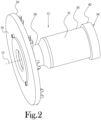
Figure 2 is a perspective view showing the thrust plate and shaft portions of the tire building drum ofFigure 1 ; -
Figure 3 is a perspective view showing the thrust plate, shaft, and actuator portions of the tire building drum ofFigure 1 ; -
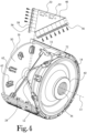
Figure 4 is a partial cutaway, partially exploded perspective view of the tire building drum ofFigure 1 ; -
Figure 5 is a cross-sectional side view showing the tire building drum ofFigure 1 in a first position; -
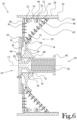
Figure 6 is a cross-sectional side view showing the tire building drum ofFigure 1 in a second position; -
Figure 7 is a cross-sectional side view showing another embodiment of a tire building drum constructed in accordance with several features of the present general inventive concept, with the tire building drum shown in a first position; -
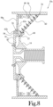
Figure 8 is a cross-sectional side view showing the tire building drum ofFigure 7 in a second position; -
Figure 9 is a cross-sectional side view showing another embodiment of a tire building drum constructed in accordance with several features of the present general inventive concept, with the tire building drum shown in a first position; -
Figure 10 is a cross-sectional side view showing the tire building drum ofFigure 9 in a second position -
Figure 11 is a partial cross-sectional side view showing another embodiment of a tire building drum constructed in accordance with several features of the present general inventive concept, with the tire building drum shown in a first position; -
Figure 12 is a partial cross-sectional side view showing the tire building drum ofFigure 11 in a second position -
Figure 13 is a partial cross-sectional side view showing another embodiment of a tire building drum constructed in accordance with several features of the present general inventive concept, with the tire building drum shown in a first position; -
Figure 14 is a partial cross-sectional side view showing the tire building drum ofFigure 13 in a second position; -
Figure 15 is a partial cross-sectional side view showing another embodiment of a tire building drum constructed in accordance with several features of the present general inventive concept, with the tire building drum shown in a first position; and -
Figure 16 is a partial cross-sectional side view showing the tire building drum ofFigure 15 in a second position. - According to several features a tire building drum is provided having a working surface which is capable of expansion and contraction within an increased range of motion compared to more conventional tire building drums, and with increased stability compared to certain prior art tire building drums. One embodiment of a tire building drum, or "drum," is illustrated generally at 10 in the accompanying figures. Referring initially to
Figures 1-3 , thedrum 10 includes generally amain shaft 12 which extends at least partially along a longitudinalcentral axis 13 of thedrum 10. Anannular thrust plate 16 extends generally radially outwardly from theshaft 12 at afirst end 18 of thedrum 10. Anactuator 14 is disposed along thecentral axis 13 at asecond end 20 of thedrum 10, and is movable along thecentral axis 13 of thedrum 10 in relation to thethrust plate 16. As will be discussed in further detail below, a plurality of outer-circumference-definingarcuate segments 26 are movably mounted about an outer circumference of thedrum 10 such that axial movement of theactuator 14 in relation to thethrust plate 16 results in radial movement of thesegments 26 toward and away from thecentral axis 13 of thedrum 10, thereby resulting in expansion and contraction of the outer circumference of thedrum 10. -
Figures 1-6 illustrate adrum 10 according to the invention. With reference toFigure 2 theshaft 12 includes generally an elongated hollow member which extends coaxially along the longitudinalcentral axis 13 of thedrum 10. Afirst end 28 of theshaft 12 is secured to a central portion of thethrust plate 16 along thecentral axis 13, and asecond end 30 of theshaft 12 extends axially inwardly from thethrust plate 16 and traverses a medial plane of thedrum 10, terminating proximate thesecond end 20 of thedrum 10. Thesecond end 30 of theshaft 12 defines one or more connectors or other features for securing theshaft 12 to a mounting fixture of a tire building machine, of the type known to one of skill in the art. In the illustrated embodiment, the shaftsecond end 30 defines a generally cylindrical shape having a smooth cylindricalouter surface 32, an openaxial end 34, and a threaded cylindricalinner surface 36. The threadedinner surface 36 of theshaft 12 is of sufficient size and shape to allow thesecond end 30 of theshaft 12 to be threadably secured onto an externally-threaded cylindrical portion of a mounting fixture of a tire building machine. - With reference to
Figures 2-6 , anannular actuator 14 is slidably received along the outercylindrical surface 32 of thesecond end 30 of theshaft 12. In several embodiments, theactuator 14 defines a generally conical, truncated-conical, or other such tapered frustum shape. For example, in the illustrated embodiment, theactuator 14 generally defines a smooth, cylindricalinner surface 38 which is shaped to closely conform to the cylindricalouter surface 32 of the main shaftsecond end 30, and an outercircumferential surface 22 which tapers radially and axially inwardly toward thefirst end 18 of thedrum 10. In the illustrated embodiment, thesecond end 30 of theshaft 12 defines anannular flange 40 extending radially outwardly therefrom. The cylindricalinner surface 38 of theactuator 14 is configured to slide along the cylindricalouter surface 32 of the shaftsecond end 30. However, the cylindricalinner surface 38 of theactuator 14 is not sufficiently large in diameter to receive theflange 40 of the shaftsecond end 30 therethrough. Thus, theflange 40 and thethrust plate 16 cooperate to limit slidable movement of theactuator 14 along themain shaft 12 between a first position (seeFigure 5 ), in which theactuator 14 is adjacent theflange 40, and a second position (seeFigure 6 ), in which theactuator 14 is adjacent aninner surface 50 of thethrust plate 16. - The tapered, annular
outer surface 22 of theactuator 14 cooperates with theinner surface 50 of thethrust plate 16 to define a radially-inwardly taperedannular void space 24 between the actuator 14 and thethrust plate 16. Theannular void space 24 has an axial dimension which is generally parallel to thecentral axis 13 of thedrum 10 and which is governed by the distance of separation between the actuator 14 and thethrust plate 16. In other words, the axial length of theannular void space 24 is expandable and contractible as the result of movement of theactuator 14 between the first and second positions. - Referring to
Figure 1 , thedrum 10 further includes a plurality of outer-circumference-definingarcuate segments 26 having at least partially mating side edges 42, such that thesegments 26 may fit adjacent one another to collectively define a cylindrical outer workingsurface 44 of thedrum 10. As shown inFigures 3-6 , a plurality oframp members 46 are provided in a generally cylindrical configuration within theannular void space 24 between the actuator 14 and thethrust plate 16, with eachramp member 46 being secured to aninner surface 48 of a correspondingsegment 26. As shown inFigures 4-6 , the perimeter of eachramp member 46 is generally trapezoidal or triangular in shape, and in the illustrated embodiment is right-triangular, defining a radially outwardly facingsurface 52 which is generally parallel to thecentral axis 13 of thedrum 10 and fixed in relation to aninner surface 48 of a correspondingsegment 26, afirst side surface 54 extending generally radially outwardly from thecentral axis 13 along the thrust plateinner surface 50, and asecond side surface 56 extending at an angle radially outwardly from thecentral axis 13 axially toward thesecond end 20 of thedrum 10 along the taperedannular surface 22 of theactuator 14. - In accordance with several features a plurality of guide mechanisms are interposed between the
thrust plate 16 and each ramp memberfirst side surface 54, and between the actuator 14 and each ramp membersecond side surface 56, to limit movement of eachramp member 46 to radial movement toward and away from thecentral axis 13 of thedrum 10 along the taperedannular surface 22 of theactuator 14 and along theinterior surface 50 of thethrust plate 16. For example, in the present case, an elongatedfirst guide rail 58 is fixed along the length of thefirst side surface 54 of eachramp member 46, and an elongatedsecond guide rail 60 is fixed along thesecond side surface 56 of eachramp member 46. Each first andsecond guide rail guide rail first guide rail 58, afirst guide block 62 is fixed to theinner surface 50 of thethrust plate 16 at a location along the outer periphery of the thrust plateinner surface 50 corresponding to a location of the associatedfirst guide rail 58. Likewise, for each second guide rail 60 asecond guide block 64 is fixed to the outer periphery of the taperedannular surface 22 of theactuator 14 at a location along a circumference of the actuator 14 corresponding to a location of the associatedsecond guide rail 60. Eachguide block guide rail guide rail second guide block central axis 13 of thedrum 10. - It will be recognized that, because each
guide rail ramp member 46, and because eachguide block guide rail plate 16 or theactuator 14, the ability of eachramp member 46 to move in relation to theactuator 14 and thethrust plate 16 in directions other than along the lengths of associatedguide rails guide block guide rail ramp member 46 to move in relation to theactuator 14 and thrustplate 16 in directions other than along the lengths of associatedguide rails - Sometimes, the guide mechanisms and other features of the
drum 10 are dimensioned and configured to allow a relatively large range of motion of theramp members 46, thus allowing a relatively large range of expansion and contraction of the cylindrical outer workingsurface 44 of thedrum 10, while maintaining stability of the individualarcuate segments 26 in relation to one another. For example, in the illustrated embodiment, the shaftfirst end 28 tapers radially inwardly along the axial length of theshaft 12 toward thethrust plate 16, such that the axially inward limits of theannular void space 24 are defined by the inwardly tapered portion of the shaftfirst end 28. In this embodiment, when theactuator 14 is in the first position nearest thesecond end 20 of the drum 10 (seeFigure 5 ), eachramp member 46 is positioned radially inwardly toward theshaft 12 between the actuator 14 and thethrust plate 16. In this position, each of the first andsecond guide rail inner surface 48 of a correspondingsegment 26 to the radially inwardly tapered portion of the shaftfirst end 28. In a the illustrated embodiment, when thedrum 10 is in the first position, thethrust plate 16 and theactuator 14 each extend radially outwardly from thecentral axis 13 to a distance approximately even with the interfaces of theramp members 46 with thearcuate segments 26. Thus, when theactuator 14 is positioned in the first position, each of the guide blocks 62, 64 is positioned at a radially outward end of arespective guide rail inner surface 48 of a correspondingsegment 26. - As shown in
Figure 6 , movement of theactuator 14 along theshaft 12 toward the second position reduces the axial length of theannular void space 24 and forces each of the guide blocks 62, 64 axially toward theirrespective guide rails first end 28 radially outward and axially toward thesecond end 20 of thedrum 10, such axial assertion of the guide blocks 62, 64 against theirrespective guide rails ramp member 46 to slide radially outwardly from between the actuator 14 and thethrust plate 16 along the first and second guide blocks 62, 64. Thus, movement of theactuator 14 toward thethrust plate 16 results in radial expansion of theramp members 46 in relation to theshaft 12 and corresponding radial expansion of the workingsurface 44 defined by thearcuate segments 26. Conversely, movement of theactuator 14 away from thethrust plate 16 and toward the first position expands the axial length of theannular void space 24, thereby causing each ramp member to slide radially inwardly along the first and second guide blocks 62, 64 toward thecentral axis 13 of thedrum 10, and thereby collapsing the workingsurface 44 defined by each of thearcuate segments 26. Thus, by moving theactuator 14 between the first and second positions along theshaft 12, the workingsurface 44 of thedrum 10 may be expanded and collapsed. - In some cases, the
actuator 14 is dimensioned such that, when thedrum 10 is in the second position, the first and second guide blocks 62, 64 are each positioned at radially inward ends of theirrespective guide rails actuator 14 defines a circumferential leadingedge 66 at an interface of the cylindricalinner surface 38 of theactuator 14 and a side surface of theactuator 14 facing thethrust plate 16. The leadingedge 66 of theactuator 14 extends proud to the remainder of theactuator 14, such that, when thedrum 10 is in the second position, the leadingedge 66 of theactuator 14 abuts theinner surface 50 of thethrust plate 16. In this configuration, each of the second guide blocks 64 is positioned at a radially inward end of a correspondingsecond guide rail 60. Similarly, in the illustrated configuration, theactuator 14 defines acircumferential trailing edge 68 at the interface of the cylindricalinner surface 38 of theactuator 14 and a side surface of theactuator 14 facing theflange 40 of the shaftsecond end 30. The trailingedge 68 extends axially outwardly of the remainder of theactuator 14 such that, when thedrum 10 is in the first position, the trailingedge 68 of theactuator 14 abuts theflange 40. In this configuration, each of the second guide blocks 64 is positioned at a radially outward end of a correspondingsecond guide rail 60. Those of skill in the art will recognize other suitable features which may be included for defining the positional relationship of theactuator 14 in relationship to thethrust plate 16 andflange 40 in the first and second positions. Sometimes, suitable stops may be positioned along thethrust plate 16, along theflange 40, at radially inward ends of the guide rails 58, 60 and/or along theshaft 12 to define the first and second positions of theactuator 14 and to limit continued movement of theactuator 14 toward thethrust plate 16 beyond the first and second positions. - With reference to
Figures 4-6 , a plurality of circumferentially-extending throughopenings 70 are provided at corresponding locations through each of theramp members 46, and at least one elasticallyresilient band 72 is received through each of thecircumferentially corresponding openings 70 about a circumference of thedrum 10. Thebands 72 are configured to stretch when theramp members 46 are expanded through movement of theactuator 14 toward the second position, and to assert radially inward force on theramp members 46, thereby urging theramp members 46 radially inward toward theshaft 12 of thedrum 10 when the actuator is moved toward the first position. Thus, in these embodiments, theactuator 14 and thethrust plate 16 may be driven toward one another from the first position to the second position by a pneumatic, hydraulic, or other such device, and, upon disengagement of the device, thebands 72 may assist in forcing theramp members 46 radially inward toward theshaft 12 and allowing theactuator 14 and thrustplate 16 to return to the first position. However, it will be recognized that inclusion of the at least oneband 72 and correspondingopenings 70 in theramp members 46 is not necessary to accomplish thedrum 10. Upon circumstances, thedrum 10 may be driven by a rotary actuator or other such device wherein theactuator 14 and/or thrustplate 16 may be positively driven between the first and second positions. - It will be appreciated by one of skill in the art that the above-described configuration of the inwardly tapered shaft
first end 28, in combination with the dimensioning of the peripheries of thethrust plate 16 andactuator 14, the positioning of the guide blocks 62, 64 at such peripheries, and the configuration of theramp members 46 and the first andsecond guide rails second guide rail first end 28 and radially outwardly to respective opposite ends of theinternal surfaces 48 of thesegments 26, serves to substantially maximize the effective range of expansion and contraction of the workingsurface 44 of thedrum 10. Furthermore, it will be appreciated by one of skill in the art that the above-discussed fixation of the guide rails 58, 60 torespective ramp members 46, and the above-discussed fixation of the various guide blocks 62, 64 to thethrust plate 16 andactuator 14, serves to limit the presence of tolerances or dimensional allowances between mating surfaces of the above-discussed guide mechanisms, thereby maintaining stability of thesegments 26 throughout expansion and contraction of the workingsurface 44 of thedrum 10. - Occasionally, the positional relationship of the first and
second guide rails first guide rails 58 may be mounted in a radial configuration about the perimeter of theinner surface 50 of thethrust plate 16, with the first guide blocks 62 being mounted along the lengths of the first side surfaces 54 of theramp members 46. Likewise, thesecond guide rails 60 may be mounted in a radial configuration about theouter surface 22 of theactuator 14, with second guide blocks 64 being mounted along the lengths of the second side surfaces 56 of theramp members 46. - Figures 7-18 illustrate cross-sectional views of several additional embodiments constructed in accordance with several features of the present general inventive concept. In several embodiments, a first type of guide mechanism is interposed between each
ramp member 46 and either theactuator 14 or thethrust plate 16, and a second type of guide mechanism is interposed between eachramp member 46 and the other of theactuator 14 or thethrust plate 16. In several embodiments, one type of guide mechanism is configured to provide increased stability between eachramp member 46 and its associatedactuator 14 or thrustplate 16, while the other type of guide mechanism is configured to allow increased range of movement between eachramp member 46 and its associatedactuator 14 or thrustplate 16. - For example, in
Figures 7 and8 , a plurality offirst guide mechanisms 74 are provided, with onefirst guide mechanism 74 being interposed between eachramp member 46 and thethrust plate 16. In the illustrated embodiment, eachfirst guide mechanism 74 comprises afirst guide block 62a fixed along thefirst side surface 54 of arespective ramp member 46, and asecond guide block 62b fixed to theinterior surface 50 of thethrust plate 16 at a location along an outer perimeter of thethrust plate 16 in radial alignment with the associatedfirst guide block 62a. Similar to the embodiment discussed above, each of the first andsecond guide blocks first guide block 62a is configured to face, and radially align with, an elongated channel of the correspondingsecond guide block 62b. In the present case, eachfirst guide mechanism 74 further includes anintermediary guide rail 58a interposed between, and in slidable engagement with, each of the channels of the corresponding first andsecond guide blocks intermediary guide rail 58a defines first and second guide surfaces along opposite longitudinal sides of theguide rail 58a, such that each first guide block channel is in slidable engagement with a first guide surface along a first longitudinal side of theintermediary guide rail 58a, and each second guide block channel is in slidable engagement with a second guide surface along a second longitudinal side of theintermediary guide rail 58a. - A plurality of
second guide mechanisms 76 are provided, with onesecond guide mechanism 76 being interposed between eachramp member 46 and theouter surface 22 of theactuator 14. In the illustrated embodiment, eachsecond guide mechanism 74 comprises anelongated guide rail 60 fixed along thesecond side surface 56 of theramp member 46, and aguide block 64 fixed to the annularouter surface 22 of theactuator 14 at a location along a circumference of the actuator 14 corresponding to a location of the associatedguide rail 46. - Referring to
Figure 7 , as discussed above, with theactuator 14 in the first position, eachguide block 64 of eachsecond guide mechanism 76 is positioned at a radially outward end of an associatedguide rail 60 of thesecond guide mechanism 76. With regard to the first andsecond guide blocks first guide mechanism 74, eachfirst guide block 62a is positioned at a radially inward end of an associatedintermediary guide rail 58a, and eachsecond guide block 62b of eachfirst guide mechanism 74 is positioned at a radially outward end of an associatedintermediary guide rail 58a. Referring toFigure 8 , with theactuator 14 in the second position, eachguide block 64 of eachsecond guide mechanism 76 is positioned at a radially inward end of an associatedguide rail 60 of thesecond guide mechanism 76. In this configuration, eachfirst guide block 62a of eachfirst guide mechanism 74 is positioned at a radially outward end of an associatedintermediary guide rail 58a, and eachsecond guide block 62b is positioned at a radially inward end of an associatedintermediary guide rail 58a. - In this case, it will be recognized that the
second guide mechanisms 76 cooperate to maintain stability between the actuator 14 and thevarious segments 26 forming the cylindrical outer workingsurface 30 of thedrum 10 throughout expansion and contraction of the cylindrical outer workingsurface 44 by limiting the presence of tolerances or dimensional allowances between mating surfaces of the above-discussedsecond guide mechanisms 76. It will be further recognized that the range of movement of eachramp member 46 in relation to theactuator 14 is governed by the length that theguide block 64 of eachsecond guide mechanism 76 may travel between respective ends of the associatedguide rail 60. However, the range of movement of eachramp member 46 in relation to thethrust plate 16 is governed by the sum of the length that thefirst guide block 62a of eachfirst guide mechanism 74 may travel between respective ends of the associatedintermediary guide rail 58a and the length that thesecond guide block 62b may travel between respective ends of the associatedintermediary guide rail 58a. Therefore, it will be recognized that, when comparing first andsecond guide mechanisms first guide mechanisms 74 may provide for an increased range of movement of theramp members 46 as compared to thesecond guide mechanisms 76. Alternatively, thefirst guide mechanisms 74 may provide for an equal range of movement of theramp members 46 as thesecond guide mechanisms 76 while employing anintermediary guide rail 58a having a shorter radial length than is required by theguide rail 60 of thesecond guide mechanism 76. In light of the above, in the embodiment ofFigures 7-8 , eachguide rail 64 of eachsecond guide mechanism 76 extends along the entire length of thesecond side surface 56 of theramp member 46, and further extends radially inwardly beneath thefirst guide mechanism 74. Thus, thesecond guide mechanism 76 is configured to allow a maximized range of expansion and contraction of thedrum 10a, while further assisting in maintaining stability between eachramp member 46 and theactuator 14. -
Figures 9 and 10 illustrate anotherdrum 10b constructed in accordance with several features of the present general inventive concept. In the embodiment ofFigures 9 and 10 , a plurality offirst guide mechanisms 74b are provided, with onefirst guide mechanism 74b being interposed between thesecond side surface 56 of eachramp member 46 and theactuator 14. A plurality ofsecond guide mechanisms 76b of the type described above are provided, with onesecond guide mechanism 76 being interposed between thefirst side surface 54 of eachramp member 46 and thethrust plate 16. In the illustrated embodiment, theguide rail 60b of eachsecond guide mechanism 76b is fixed along the length of thesecond side surface 54 of acorresponding ramp member 46, and theguide block 64b of eachsecond guide mechanism 76b is fixed along theinterior surface 50 of thethrust plate 16 at a location along an outer circumference of thethrust plate 16 in radial alignment with theguide rail 60b. Thefirst guide block 62c of eachfirst guide mechanism 74b is fixed to thesecond side surface 56 of acorresponding ramp member 46, and thesecond guide block 62d of eachfirst guide mechanism 74b is fixed to theannular surface 22 of theactuator 14. Thus, in the embodiment ofFigures 9 and 10 , thesecond guide mechanism 76b provides improved stability between eachramp member 46 and thethrust plate 16, while a void space is provided between eachramp member 46 and theactuator 14, radially inwardly of eachfirst guide mechanism 74b. -
Figures 11 and 12 illustrate anotherdrum 10c wherein a plurality offirst guide mechanisms 74c are provided, with one first guide mechanism 44c being interposed between thefirst side surface 54 of eachramp member 46 and thethrust plate 16. In the illustrated embodiment, eachfirst guide mechanism 74c comprises an elongatedcylindrical member 80 slidably received within anelongated tubular member 82 in telescopic fashion, such that thecylindrical member 80 is limited to sliding movement along a coaxis of thecylindrical member 80 and thetubular member 82. In the present case, eachfirst guide mechanism 74c is received within avoid space 84 defined along thefirst side surface 54 of acorresponding ramp member 46. Eachcylindrical member 80 is secured to a portion of theramp member 46 within thevoid space 84 proximate aninterior surface 48 of a corresponding circumference-definingsegment 26 and proximate thethrust plate 16, and eachtubular member 76 is secured to a portion of themain shaft 12 proximate thethrust plate 16. Eachvoid space 84 defined along thefirst side surface 54 of eachramp member 46 is sized and shaped to closely conform to an exterior surface of thetubular member 82, such that thevoid space 84 andtubular member 82 cooperate to provide stability to theramp member 46 during expansion and collapse of thedrum 10c. In the embodiment ofFigures 11 and 12 , a plurality ofsecond guide mechanisms 76c are provided as discussed above with regard toFigures 9 and 10 , with onesecond guide mechanism 76c being interposed between thesecond side member 56 of eachramp member 46 and theactuator 14. -
Figures 13 and 14 illustrate anotherdrum 10d wherein, plurality offirst guide mechanisms 74d are provided, with onefirst guide mechanism 74d being interposed between thesecond side surface 56 of eachramp member 46 and theactuator 14. In the illustrated embodiment, eachfirst guide mechanism 74d includes a pair ofrollers 86 rotatably secured in a tandem orientation along a radial dimension of the taperedannular surface 22 of theactuator 14, between the actuator 14 and an associatedsecond side surface 56 of aramp member 46. Each of the pair ofrollers 86 is configured to roll along thesecond side surface 56 of an associatedramp member 46 between opposite first and second ends of thesecond side surface 56 of theramp member 46. In certain cases, eachroller 86 defines an annular groove, channel, lip, or other such guide which is configured to engage a corresponding linear guide defined along thesecond side surface 56 of theramp member 46, thereby limiting theramp member 46 from movement along axial dimensions of therollers 86. In several embodiments, at least one resilient spring member is provided to urge eachramp member 46 toward its associatedrollers 86. For example, in the illustrated embodiment, a throughopening 70d is defined at a central portion of eachramp member 46 along a circumferential direction of thedrum 10d. A resilientlyelastic band 72d is received through each of the throughopenings 70d in the ramp members about the circumference of thedrum 10d, such that theband 72d urges each of theramp members 46 toward the central axis of thedrum 10d, thereby maintaining contact between therollers 86 and the associatedsecond side members 56 of theramp members 46 throughout expansion and collapse of thedrum 10d. -
Figures 15 and 16 illustrate anotherdrum 10e wherein, in addition to therollers 86 described above, eachfirst guide mechanism 74e disposed between eachramp member 46 and theactuator 14 further includes a cantileveredlever arm 88 which is rotatably secured at afirst end 90 thereof to a portion of theactuator 14. Eachlever arm 88 is configured to rotate along a plane extending radially outwardly from thedrum 10e. Anadditional roller 94 is rotatably secured to asecond end 92 of eachlever arm 88 and is configured to roll along aslot 96 defined by an associatedramp member 46. The orientation of eachslot 96 along its associatedramp member 46 and the orientation, shape, and length of eachlever arm 88 in relation to theslot 96 is such that thelever arm 88 andslot 96 cooperate to maintain intimate contact between therollers 82 and the associatedsecond side surface 56 of theramp members 46 throughout expansion and collapse of thedrum 10e, thereby providing stability to theramp members 46 during expansion and collapse of thedrum 10e.
Claims (16)
- A tire building drum (10) for forming a component of a tire, said drum (10) having a central axis (13) and opposite first (28) and second axial ends (20), said drum (10) comprising:a shaft (12) extending along said axis (13), said shaft (12) defining an outer circumference proximate to said second axial end (20) and a tapered portion that tapers radially inwardly along an axial length of the shaft proximate said first axial end (28), the tapered portion defining an axially inward limit of an annular void space (24) proximate said first axial end (28), wherein the shaft (12) is hollow such that it has an inner surface with an inner diameter and a threaded portion;a plurality of substantially arcuate segments (26) arranged in a side-by-side circumferential relationship with respect to one another about said shaft to define a segmented, radially expandable and collapsible cylindrical outer working surface (44), each said segment (26) having a first end proximate said drum (10) first axial end and a second end proximate said drum second axial end;an annular thrust plate (16) extending radially outwardly from said shaft (12) axially outward of said tapered portion, said thrust plate (16) defining a substantially planar axially interior surface;an actuator (14) defines a circumferential trailing edge extending axially outwardly of the remainder of the actuator (14) such that, when the drum (10) is in the first position the trailing edge abutes a flange and when the drum (10) is in said second position the leading edge of the actuator (14) abutes the inner surface of a thrust plate (16);an annular actuator (14) received about said shaft (12) and movable along said axis (13) between a first position proximate said drum second end and a second position proximate said drum first end, said actuator (14) defining a radially and axially inwardly tapered annular outer surface;a plurality of first linear guide rails, each said first linear guide rail having a first end secured proximate said first end of a respective one of said segments and a second end extending radially inwardly along said thrust plate (16) interior surface; a plurality of second linear guide rails, each said second linear guide rail having a first end secured proximate said second end of a respective one of said segments and a second end extending radially and axially inwardly along said actuator (14) outer surface;wherein said thrust plate (16) is slidably secured to each said first linear guide rail and said actuator (14) is slidably secured to each said second linear guide rail, and wherein each of said second ends of said first and second linear guide rails extends radially inward of said shaft (12) outer circumference toward and into said annular void space (24) defined on said shaft tapered portion when said actuator (14)is in said first position;whereby each of said first and second linear guide rails moves radially outward along said thrust plate (16) interior surface and said actuator (14) outer surface in response to movement of said actuator (14) toward said second position, thereby moving each of said segments radially outwardly from said axis (13) and expanding said cylindrical outer working surface, and each of said first and second linear guide rails moves radially inward along said thrust plate (16) interior surface and said actuator outer surface in response to movement of said actuator (14) toward said first position, thereby moving each of said segments radially inwardly toward said axis (13) and collapsing said cylindrical outer working surface.
- The tire building drum of claim 1 further comprising a plurality of first guide followers mounted in circumferentially spaced apart locations about said thrust plate (16) interior surface, each said first guide follower slidably engaging one of said first linear guide rails and limiting said guide rail to radial movement along said thrust plate (16) interior surface.
- The tire building drum of claim 2, each said first guide follower being mounted along a radially outer edge of said thrust plate interior surface.
- The tire building drum of claim 3 further comprising a plurality of second guide followers mounted in circumferentially spaced apart locations about said actuator (14) outer surface, each said second guide follower slidably engaging a respective one of said second linear guide rails and limiting said second linear guide rails to radial movement along said actuator (14) outer surface as said actuator moves between said first and second positions.
- The tire building drum of claim 4, each said second guide follower being mounted along a radially outer edge of said actuator (14) outer surface.
- The tire building drum of claim 5, each said first guide follower being adjacent inner surfaces of said segments when said actuator (14) is in said first position.
- The tire building drum of claim 5, each said second guide follower being adjacent inner surfaces of said segments when said actuator (14) is in said first position.
- The tire building drum of claim 5, each of said first and second guide followers being adjacent the second end of its respective one of the linear guide rails to which it is respectively engaged when said actuator (14) is in said second position.
- The tire building drum of claim 8 wherein each said first linear guide rail second end is adjacent the second end of a corresponding respective one of the second linear guide rails.
- The tire building drum of claim 1 further comprising a plurality of ramp members (46) disposed in circumferentially spaced apart locations about said shaft (12)between said actuator and said thrust plate (16), each said ramp member (46) having an axially extending, radially outer end secured along an inner surface of one of said segments, a first side surface extending parallel to said thrust plate (16) interior surface, and a second side surface extending parallel to said actuator (14) outer surface, each said first linear guide rail being fixed to a corresponding one of said ramp member (46) first side surfaces, each said second linear guide rail being fixed to a corresponding one of said ramp member (46) second side surfaces.
- The tire building drum of claim 10, each ramp member (46) defining a substantially flat, right triangular shape extending along an axial dimension of said drum and radially outwardly from said axis.
- The tire building drum of claim 10, each said ramp member (46) being biased toward said axis.
- The tire building drum of claim 12 further comprising at least one elastically resilient band extending circumferentially about said axis and biasing said ramp members (46) toward said axis when said actuator (14) is not in said first position.
- The tire building drum of claim 1, said actuator (14) defining a cylindrical inner surface sized and shaped to conform to said shaft outer circumference and to limit movement of said actuator (14) to sliding movement along said shaft.
- The tire building drum of claim 14, said shaft defining an annular flange extending radially outwardly from said shaft second end, said actuator (14) abutting said flange in said first position.
- The tire building drum of claim 14, said actuator (14) defining a circumferential leading portion facing said thrust plate interior surface, said leading portion abutting said thrust plate interior surface in said second position.
Applications Claiming Priority (2)
| Application Number | Priority Date | Filing Date | Title |
|---|---|---|---|
| US201361832544P | 2013-06-07 | 2013-06-07 | |
| PCT/US2014/040885 WO2014197579A1 (en) | 2013-06-07 | 2014-06-04 | Tire building drum with increased range of movement |
Publications (4)
| Publication Number | Publication Date |
|---|---|
| EP3003698A1 EP3003698A1 (en) | 2016-04-13 |
| EP3003698A4 EP3003698A4 (en) | 2016-12-28 |
| EP3003698B1 true EP3003698B1 (en) | 2025-01-29 |
| EP3003698C0 EP3003698C0 (en) | 2025-01-29 |
Family
ID=52004453
Family Applications (1)
| Application Number | Title | Priority Date | Filing Date |
|---|---|---|---|
| EP14808335.5A Active EP3003698B1 (en) | 2013-06-07 | 2014-06-04 | Tire building drum with increased range of movement |
Country Status (6)
| Country | Link |
|---|---|
| US (1) | US9855715B2 (en) |
| EP (1) | EP3003698B1 (en) |
| KR (1) | KR102205188B1 (en) |
| CN (1) | CN105658419B (en) |
| RU (1) | RU2659249C2 (en) |
| WO (1) | WO2014197579A1 (en) |
Families Citing this family (7)
| Publication number | Priority date | Publication date | Assignee | Title |
|---|---|---|---|---|
| FR3031695B1 (en) * | 2015-01-16 | 2017-02-24 | Michelin & Cie | DRUM MAKING A PNEUMATIC BRAKE |
| EP3277489B1 (en) * | 2015-03-31 | 2020-12-02 | Pirelli Tyre S.p.A. | Process and expandable forming drum for building tyres for vehicle wheels |
| BR112020011729B1 (en) * | 2017-12-28 | 2023-05-09 | Pirelli Tyre S.P.A | DRUM FOR THE CONSTRUCTION OF A TIRE FOR TWO-WHEEL VEHICLES, AND METHOD FOR CONTROLLING THE GEOMETRY OF A CONSTRUCTION DRUM |
| EP3917765B1 (en) * | 2019-01-28 | 2024-03-27 | Davian Enterprises, LLC | Expandable belt and tread drum with reverse offset fingers |
| EP4139120B1 (en) | 2020-04-22 | 2025-08-06 | William A. Jones | Shoulder assembly for tire building machine |
| KR102834419B1 (en) | 2020-05-29 | 2025-07-14 | 케네쓰 맥클리리 | Transfer ring and transfer ring shoe with reduced air entrapment feature |
| WO2022120117A2 (en) | 2020-12-03 | 2022-06-09 | Davian Enterprises, Llc (Dba Wyko Tire Technologies) | Expandable belt and tread drum with magnetic deck fixing |
Family Cites Families (142)
| Publication number | Priority date | Publication date | Assignee | Title |
|---|---|---|---|---|
| USRE22369E (en) | 1943-08-31 | Collapsible form | ||
| US1233567A (en) | 1916-10-07 | 1917-07-17 | William C Furry | Mold for forming concrete structures. |
| US1750728A (en) | 1928-04-30 | 1930-03-18 | George A Robison | Well-tool grab |
| US2168897A (en) | 1937-03-23 | 1939-08-08 | Akron Standard Mold Co | Tire building drum |
| US2353767A (en) | 1937-12-29 | 1944-07-18 | Akron Standard Mold Co | Tire building drum |
| US2201469A (en) | 1938-03-07 | 1940-05-21 | Akron Standard Mold Co | Collapsible form |
| US2335169A (en) | 1941-04-19 | 1943-11-23 | Akron Standard Mold Co | Tire-making drum |
| US2367831A (en) | 1942-11-24 | 1945-01-23 | Firestone Tire & Rubber Co | Collapsible form |
| US2529861A (en) | 1945-09-01 | 1950-11-14 | White S Dental Mfg Co | Adjustable seat supporting structure |
| US2614057A (en) | 1951-02-21 | 1952-10-14 | Us Rubber Co | Tire building drum |
| US2699198A (en) | 1951-08-04 | 1955-01-11 | Goodrich Co B F | Tire building drum |
| US2715932A (en) | 1953-03-04 | 1955-08-23 | Goodyear Tire & Rubber | Tire building drum |
| US2728616A (en) | 1953-11-24 | 1955-12-27 | Fafnir Bearing Co | Bearing |
| FR1227567A (en) | 1958-06-05 | 1960-08-22 | Firestone Tire & Rubber Co | Tire forming drum |
| US3101289A (en) | 1959-04-24 | 1963-08-20 | Pirelli | Method of making expansible tubular diaphragms for tire building drums |
| FR1242880A (en) | 1959-06-25 | 1960-10-07 | Kleber Colombes | Tire building drum |
| NL253095A (en) | 1959-07-03 | |||
| US3207648A (en) | 1962-02-01 | 1965-09-21 | Akron Standard Mold Co | Tire building apparatus |
| US3140216A (en) * | 1962-04-18 | 1964-07-07 | Akron Standard Mold Co | Precision tire building drum |
| US3405023A (en) | 1964-05-19 | 1968-10-08 | Goodrich Co B F | Tire building drum |
| US3346434A (en) | 1964-06-09 | 1967-10-10 | Akron Standard Mold Co | Tire building drum |
| GB1050820A (en) | 1964-08-19 | |||
| US3507528A (en) | 1965-02-16 | 1970-04-21 | Westinghouse Electric Corp | Locking device |
| US3375154A (en) | 1965-04-09 | 1968-03-26 | Akron Standard Mold Co | Tire building drum |
| US3408244A (en) | 1965-04-28 | 1968-10-29 | Nat Standard Co | Tire assembling apparatus and apparatus for forming side walls for tires |
| US3489634A (en) | 1965-06-24 | 1970-01-13 | Uniroyal Inc | Apparatus for building tires and the like |
| FR95396E (en) | 1966-02-25 | 1970-09-11 | Nrm Corp | Radial carcass tire making drum. |
| US3485700A (en) | 1966-07-20 | 1969-12-23 | Ralph F Cooper | Tire building drum |
| NL6716660A (en) | 1966-12-30 | 1968-07-01 | ||
| BG18591A3 (en) | 1967-02-08 | 1975-02-25 | ||
| FR1531460A (en) | 1967-04-26 | 1968-07-05 | Uniroyal Englebert France | Axially collapsible and retractable pulley |
| US3695974A (en) | 1970-03-09 | 1972-10-03 | Gen Tire & Rubber Co | Tire building drum |
| US3644162A (en) | 1970-07-06 | 1972-02-22 | Goodyear Tire & Rubber | Tire-building drum |
| US3676261A (en) | 1970-07-06 | 1972-07-11 | Goodyear Tire & Rubber | Bead setting and ply turnup apparatus |
| US3784426A (en) | 1970-12-18 | 1974-01-08 | Goodyear Tire & Rubber | Method of building tires |
| JPS5031910B1 (en) * | 1971-05-11 | 1975-10-16 | ||
| US3787262A (en) | 1971-09-24 | 1974-01-22 | Goodyear Tire & Rubber | Tire building drum |
| US3816218A (en) | 1972-03-29 | 1974-06-11 | Goodyear Tire & Rubber | Tire building drum |
| JPS5217063B2 (en) | 1972-04-11 | 1977-05-13 | ||
| US3837968A (en) | 1972-11-20 | 1974-09-24 | Goodyear Tire & Rubber | Tire building drum |
| JPS5121669B2 (en) | 1972-12-07 | 1976-07-03 | ||
| US3867229A (en) | 1974-02-01 | 1975-02-18 | Goodyear Tire & Rubber | Tire building drum |
| JPS532474B2 (en) | 1974-04-15 | 1978-01-28 | ||
| CA1062594A (en) | 1974-05-22 | 1979-09-18 | Frank R. Jellison | Building machine having an infinite number of drum settings |
| US4131500A (en) | 1974-12-09 | 1978-12-26 | Avon Tyres Limited | Tire building drum |
| US4010058A (en) | 1975-05-16 | 1977-03-01 | The Goodyear Tire & Rubber Company | Tire building drum |
| US4105487A (en) | 1975-12-27 | 1978-08-08 | Bridgestone Tire Company Limited | Process of and an apparatus for producing green tires |
| GB1568858A (en) | 1977-03-10 | 1980-06-04 | Vni I Konstrukt I Oborud Dlya | Tyre-building drum |
| JPS5463184A (en) | 1977-10-28 | 1979-05-21 | Bridgestone Tire Co Ltd | Tire forming drum |
| US4230517A (en) | 1978-03-15 | 1980-10-28 | Nrm Corporation | Modular tire building machine |
| US4149927A (en) | 1978-03-24 | 1979-04-17 | The General Tire & Rubber Company | Tire building apparatus with improved drum shoulder |
| US4155796A (en) | 1978-06-28 | 1979-05-22 | The Goodyear Tire & Rubber Company | Single section tire building drum |
| US4210482A (en) | 1978-10-25 | 1980-07-01 | Eaton Corporation | Variable width tire building drum |
| US4324604A (en) | 1978-12-22 | 1982-04-13 | The General Tire & Rubber Co. | Bead setting apparatus with retractable flange |
| JPS55103942A (en) | 1979-02-01 | 1980-08-08 | Bridgestone Corp | Forming drum for tyre |
| US4239579A (en) | 1979-05-25 | 1980-12-16 | The Goodyear Tire & Rubber Company | Tire building drum |
| US4312696A (en) | 1980-03-12 | 1982-01-26 | National-Standard Company | Tire building apparatus |
| US4325764A (en) | 1980-06-19 | 1982-04-20 | The Goodyear Tire & Rubber Company | Drum and method of shaping a radial tire |
| IT1133894B (en) | 1980-10-15 | 1986-07-24 | Pirelli | IMPROVEMENTS IN PROCESSES AND EQUIPMENT FOR THE MANUFACTURE OF TIRES |
| US4473427A (en) | 1981-06-12 | 1984-09-25 | Mitsubishi Jukogyo Kabushiki Kaisha | Radial tire manufacture apparatus |
| US4425180A (en) | 1981-07-08 | 1984-01-10 | Vsesojuzny Nauchno-Issledovatelsky I Konstruktorsky Institut Po Oborudovaniju Dlya Shinnoi Promyshlennosti | Tire casing assembly drum |
| IT1145094B (en) | 1981-09-16 | 1986-11-05 | Martinson Srl | SELF-CENTERING BEZEL |
| US4469546A (en) | 1981-12-16 | 1984-09-04 | Cooper Tire & Rubber Company | Transfer ring for a tire building machine |
| US4445962A (en) | 1982-07-01 | 1984-05-01 | The B. F. Goodrich Company | Tire building drum |
| JPS5912834A (en) | 1982-07-13 | 1984-01-23 | Bridgestone Corp | Forming drum for radial tyre forming machine |
| US4436574A (en) * | 1982-12-13 | 1984-03-13 | Eagle-Picher Industries, Inc. | Radial mandrel |
| JPS59120438A (en) | 1982-12-27 | 1984-07-12 | Bridgestone Corp | Tire molding equipment |
| JPS59202837A (en) | 1983-05-02 | 1984-11-16 | Bridgestone Corp | Tire molding apparatus |
| US4582557A (en) | 1983-12-12 | 1986-04-15 | Nrm Corporation | Tire building machine and method |
| GB8403351D0 (en) | 1984-02-08 | 1984-03-14 | Wyko Equipment Ltd | Tyre building drum |
| US4626302A (en) | 1984-09-24 | 1986-12-02 | The Goodyear Tire & Rubber Company | Tire building apparatus and method |
| DE3536816A1 (en) | 1985-10-16 | 1987-04-16 | Josef Maier | FORMWORK FOR ROUND OR MULTI-SIDED BUILDINGS |
| US4780171A (en) | 1987-08-13 | 1988-10-25 | Wyko Incorporated | Tire building machine |
| US4861173A (en) | 1987-08-17 | 1989-08-29 | Advanced Graphics Technology, Inc. | Bearing locking apparatus |
| US4861123A (en) | 1987-10-19 | 1989-08-29 | Waterloo Industries, Inc. | Integral slide formed from drawer shell |
| US4798647A (en) | 1988-01-25 | 1989-01-17 | Haas Herbert G | Releasable mounting assembly for tire building drum |
| JP2706974B2 (en) | 1989-04-25 | 1998-01-28 | 株式会社ブリヂストン | Method of folding back tire components |
| DE3925083A1 (en) | 1989-07-28 | 1991-01-31 | Continental Ag | METHOD AND DEVICE FOR PRODUCING A TIRE BLANK ON A BOMBING LEVEL |
| EP0431854B1 (en) * | 1989-12-04 | 1995-02-22 | Sumitomo Rubber Industries Limited | Drum for assembling tyre component material |
| US5089077A (en) | 1990-03-08 | 1992-02-18 | Wyko, Incorporated | Apparatus for manufacturing multiple-ply tire carcasses |
| US5047108A (en) | 1990-03-09 | 1991-09-10 | Wyko, Inc. | Tire building drum for fabricating high profile type tire carcasses |
| US5066354A (en) * | 1990-05-25 | 1991-11-19 | Cooper Tire And Rubber Company | Building drum for a tire belt-tread stock package |
| NL9001645A (en) | 1990-07-19 | 1992-02-17 | Vmi Epe Holland | MECHANISM FOR SUPPORTING AND FASTENING THE HEELS IN CONSTRUCTION OF AIR TIRES. |
| JPH0645194B2 (en) * | 1990-07-24 | 1994-06-15 | 住友ゴム工業株式会社 | Beadlock method and apparatus for green tire molding machine |
| JPH07102628B2 (en) | 1991-04-30 | 1995-11-08 | 住友ゴム工業株式会社 | Ring member forming device |
| JP3193417B2 (en) | 1991-10-07 | 2001-07-30 | 株式会社ブリヂストン | Drum for tire building |
| US5320701A (en) | 1992-11-04 | 1994-06-14 | Illinois Tool Works Inc. | Tire building drum |
| EP0613767B1 (en) | 1993-03-04 | 1998-06-10 | Bridgestone Corporation | Method of forming a green tyre |
| IT1271479B (en) | 1993-10-11 | 1997-05-28 | Pirelli | METHOD AND EQUIPMENT FOR THE CAPPING OF A COATING STRUCTURE ON A CIRCLE FOR VEHICLE TIRES |
| US5354405A (en) | 1993-11-18 | 1994-10-11 | Wyko, Inc. | Bead lock drum for use in the manufacture of vehicle tires |
| US5618374A (en) | 1994-02-10 | 1997-04-08 | Wyko, Inc. | Belt and tread drum for vehicle tire making machine |
| US5441587A (en) | 1994-08-12 | 1995-08-15 | Wyko, Inc. | Transfer ring having selective adjustability of shoe movement |
| US5709768A (en) | 1995-10-24 | 1998-01-20 | Wyko, Inc. | Apparatus with adjustable circumference made up of a plurality of interconnected shoes |
| US5635016A (en) | 1995-10-24 | 1997-06-03 | Wyko, Inc. | Transfer ring or drum apparatus with adjustable circumference |
| US5906836A (en) * | 1995-11-27 | 1999-05-25 | American Mobility Limited Partnership | Spin casting apparatus for manufacturing an item from polyurethane foam |
| IT1281105B1 (en) | 1995-12-22 | 1998-02-11 | Bridgestone Firestone Tech | TIRE FORMING DRUM |
| US5735995A (en) | 1996-02-13 | 1998-04-07 | The Steelastic Company, L.L.C. | Apparatus for applying an apex filler to a bead ring |
| DE19742035C1 (en) | 1997-09-24 | 1999-04-08 | Continental Ag | Method and drum as a device for building a green tire |
| US6004250A (en) | 1997-09-30 | 1999-12-21 | Wyko, Inc. | System and method for releaseably attaching outer segments to a drum useful in the manufacture of vehicle tires |
| US6007268A (en) | 1998-04-24 | 1999-12-28 | Specialized Marketing International, Inc. | Radial and axial locking release collar |
| US6058999A (en) | 1998-05-04 | 2000-05-09 | Wyko, Inc. | Tire manufacturing drum having simultaneous axial and radial adjustability |
| US6238292B1 (en) | 1998-05-27 | 2001-05-29 | Monadnock Lifetime Products, Inc. | Push button controlled police baton with ball bearing locking mechanism |
| US6013147A (en) | 1998-07-21 | 2000-01-11 | Wyko, Inc. | Expandable belt and tread drum |
| US20030197389A1 (en) | 1998-08-04 | 2003-10-23 | Moilanen Steven M. | Modular stamped parts transfer gripper |
| US6585022B1 (en) | 1998-09-01 | 2003-07-01 | The Goodyear Tire And Rubber Company | Tire building method and apparatus |
| US6152645A (en) | 1998-12-15 | 2000-11-28 | The United States Of America As Represented By The Secretary Of The Navy | Ball lock mechanism |
| JP4257712B2 (en) | 1999-03-08 | 2009-04-22 | 株式会社ブリヂストン | Rotating drum for tire molding |
| US6390166B1 (en) | 2000-05-19 | 2002-05-21 | Wyko, Inc. | Expandable mandrel having adjustable width |
| JP2001341212A (en) * | 2000-06-06 | 2001-12-11 | Bridgestone Corp | Tire molding apparatus |
| KR20020069223A (en) * | 2000-10-27 | 2002-08-29 | 소시에떼 드 테크놀로지 미쉐린 | Tyre building drum |
| US6457505B1 (en) | 2000-11-16 | 2002-10-01 | Wyko, Inc. | Vehicle tire building drum including bead drum positioning and side wall formation features |
| US6602372B1 (en) | 2000-11-20 | 2003-08-05 | Wyko, Inc. | Method and apparatus for control of dual collapsible mandrels |
| US6673183B2 (en) | 2001-07-31 | 2004-01-06 | Wyko, Inc. | Method and apparatus for tire carcass positioning on a drum |
| US6571682B2 (en) | 2001-07-31 | 2003-06-03 | Wyko, Inc. | Apparatus for converting circular motion to radial motion |
| US6793752B2 (en) | 2001-09-21 | 2004-09-21 | The Goodyear Tire & Rubber Company | Precision longitudinal registration of tire building drum to automated tire building system work station |
| US20050028920A1 (en) * | 2003-08-04 | 2005-02-10 | Roedseth John Kolbjoern | High crown first stage tire building drum |
| US7000905B1 (en) | 2003-08-05 | 2006-02-21 | The Crosby Group, Inc. | Retaining keeper assembly for a hoisting device |
| US7287772B2 (en) | 2004-01-12 | 2007-10-30 | West Coast Choppers, Inc. | Apparatus and method for securing an axle to a frame |
| NL1025904C2 (en) * | 2004-04-08 | 2005-10-11 | Vmi Epe Holland | Seat belt drum. |
| GB0413275D0 (en) | 2004-06-15 | 2004-07-14 | Wyko Equip | Bead lock arrangement |
| DE102004032508A1 (en) | 2004-07-06 | 2006-02-16 | Continental Aktiengesellschaft | Method and device for constructing a radial tire |
| DE102004032511A1 (en) | 2004-07-06 | 2006-02-16 | Continental Aktiengesellschaft | Method and device for positioning bead cores |
| US7288160B2 (en) | 2004-12-23 | 2007-10-30 | The Goodyear Tire & Rubber Company | Method of making a tire using a high crown uni-stage tire building drum |
| GB0506363D0 (en) * | 2005-03-30 | 2005-05-04 | Wyko Equip | Tyre building drum |
| JP4614857B2 (en) * | 2005-09-30 | 2011-01-19 | 株式会社ブリヂストン | Tire molding drum |
| GB0603700D0 (en) | 2006-02-24 | 2006-04-05 | Wyko Equip | Expandable mandrel having adjustable width |
| US7637665B2 (en) | 2006-06-30 | 2009-12-29 | Emerson Power Transmission Corporation | Bearing assembly and resilient seal element |
| US20100101732A1 (en) | 2008-10-23 | 2010-04-29 | Howley Sean E | Method and apparatus for establishing obtainable range of diameters of a working drum |
| US8056597B2 (en) | 2008-04-10 | 2011-11-15 | Bps Engineering, Llc | Cam follower assembly for thin walled cylinder of scroll shaping drum used in tire construction |
| US8701731B2 (en) | 2008-07-02 | 2014-04-22 | Davian Enterprises, LLC | Transfer ring having advantaged cam follower-camming groove aspect and method |
| US8091602B2 (en) | 2008-07-02 | 2012-01-10 | Davian Enterprises, LLC | Transfer ring having advantaged cam follower-camming groove aspect and method |
| US8757231B2 (en) | 2009-01-26 | 2014-06-24 | E. I. Du Pont De Nemours And Company | Elastomer tire sealing ring |
| DE102009003507A1 (en) * | 2009-02-19 | 2010-08-26 | Continental Reifen Deutschland Gmbh | Tire carcass manufacturing device for vehicle, has traversing unit moved on drive shaft in axial direction, where segments of bellows carrier and traversing unit are movably connected to each other by ball bearing |
| JP4897853B2 (en) * | 2009-06-10 | 2012-03-14 | 住友ゴム工業株式会社 | Tire molding drum |
| US8602078B2 (en) | 2010-06-15 | 2013-12-10 | Bps Engineering, Llc | Transfer ring or drum apparatus having adjustable circumference |
| KR101819120B1 (en) | 2010-07-09 | 2018-01-16 | 다비안 엔터프라이즈, 엘엘씨 | Anti-flex assembly |
| WO2012012697A1 (en) | 2010-07-22 | 2012-01-26 | Wyko Tire Technology, Inc. | Bearing expansion lock |
| US20120033906A1 (en) | 2010-08-03 | 2012-02-09 | Davian Enterprises, LLC | Quick Replacement Bearing Axle for Tire Transfer Ring |
| CN103140345A (en) | 2010-09-02 | 2013-06-05 | 达维阶企业有限责任公司 | Locking spacer and method |
| US8899292B2 (en) | 2010-10-14 | 2014-12-02 | Davian Enterprises, LLC | Fully supported expandable deck |
| WO2012091738A2 (en) * | 2010-12-31 | 2012-07-05 | Bps Engineering, Llc | Assembly for altering the diameter of transfer ring or drum apparatus through a broad range |
| US20130008611A1 (en) | 2011-07-05 | 2013-01-10 | Rob Marcus | Multi-Piece Sealing Sleeve |
-
2014
- 2014-06-04 WO PCT/US2014/040885 patent/WO2014197579A1/en not_active Ceased
- 2014-06-04 CN CN201480042141.8A patent/CN105658419B/en active Active
- 2014-06-04 EP EP14808335.5A patent/EP3003698B1/en active Active
- 2014-06-04 RU RU2016100306A patent/RU2659249C2/en active
- 2014-06-04 KR KR1020167000354A patent/KR102205188B1/en active Active
- 2014-06-04 US US14/295,828 patent/US9855715B2/en active Active
Also Published As
| Publication number | Publication date |
|---|---|
| US20140360673A1 (en) | 2014-12-11 |
| WO2014197579A1 (en) | 2014-12-11 |
| EP3003698A1 (en) | 2016-04-13 |
| KR20160026974A (en) | 2016-03-09 |
| EP3003698A4 (en) | 2016-12-28 |
| CN105658419B (en) | 2018-01-02 |
| RU2016100306A (en) | 2017-07-13 |
| US9855715B2 (en) | 2018-01-02 |
| KR102205188B1 (en) | 2021-01-20 |
| CN105658419A (en) | 2016-06-08 |
| EP3003698C0 (en) | 2025-01-29 |
| RU2659249C2 (en) | 2018-06-29 |
Similar Documents
| Publication | Publication Date | Title |
|---|---|---|
| US9855715B2 (en) | Tire building drum with increased range of movement | |
| US8708017B2 (en) | Assembly for altering the diameter of transfer ring or drum apparatus through a broad range | |
| EP2698243B1 (en) | Sleeveless tire building drum | |
| EP3037249B1 (en) | Sleeveless tire building drum | |
| EP2868463B1 (en) | Tire building drum | |
| EP2698244B1 (en) | Sleeveless tire building drum with interchangeable width elements | |
| EP3102399B1 (en) | Expandable belt and tread drum with varied curvature segments | |
| EP2913182A1 (en) | Transfer ring or drum apparatus with adjustable circumference | |
| EP2217434B1 (en) | Method of building tyres and drum therefor. | |
| EP0455469B1 (en) | Tire building apparatus | |
| US3817812A (en) | Drum for building green tires | |
| US7384499B2 (en) | Apparatus for tread belt assembly | |
| US9662848B2 (en) | Method and apparatus for adjusting a tire building machine | |
| EP3378636B1 (en) | Belt drum | |
| US20070187016A1 (en) | Tire manufacturing method and tire | |
| JP7189752B2 (en) | Bead transfer device | |
| TH33239B (en) | The tire's expanding cylinder has alternating fixed and expanding segments and an external layout for the inner sidewall. | |
| TH57323A (en) | The tire's expanding cylinder has alternating fixed and expanding segments and an external layout for the inner sidewall. |
Legal Events
| Date | Code | Title | Description |
|---|---|---|---|
| PUAI | Public reference made under article 153(3) epc to a published international application that has entered the european phase |
Free format text: ORIGINAL CODE: 0009012 |
|
| 17P | Request for examination filed |
Effective date: 20160105 |
|
| AK | Designated contracting states |
Kind code of ref document: A1 Designated state(s): AL AT BE BG CH CY CZ DE DK EE ES FI FR GB GR HR HU IE IS IT LI LT LU LV MC MK MT NL NO PL PT RO RS SE SI SK SM TR |
|
| AX | Request for extension of the european patent |
Extension state: BA ME |
|
| DAX | Request for extension of the european patent (deleted) | ||
| A4 | Supplementary search report drawn up and despatched |
Effective date: 20161124 |
|
| RIC1 | Information provided on ipc code assigned before grant |
Ipc: B29D 30/24 20060101AFI20161118BHEP |
|
| STAA | Information on the status of an ep patent application or granted ep patent |
Free format text: STATUS: EXAMINATION IS IN PROGRESS |
|
| 17Q | First examination report despatched |
Effective date: 20180810 |
|
| GRAP | Despatch of communication of intention to grant a patent |
Free format text: ORIGINAL CODE: EPIDOSNIGR1 |
|
| STAA | Information on the status of an ep patent application or granted ep patent |
Free format text: STATUS: GRANT OF PATENT IS INTENDED |
|
| INTG | Intention to grant announced |
Effective date: 20240829 |
|
| GRAJ | Information related to disapproval of communication of intention to grant by the applicant or resumption of examination proceedings by the epo deleted |
Free format text: ORIGINAL CODE: EPIDOSDIGR1 |
|
| STAA | Information on the status of an ep patent application or granted ep patent |
Free format text: STATUS: EXAMINATION IS IN PROGRESS |
|
| GRAP | Despatch of communication of intention to grant a patent |
Free format text: ORIGINAL CODE: EPIDOSNIGR1 |
|
| STAA | Information on the status of an ep patent application or granted ep patent |
Free format text: STATUS: GRANT OF PATENT IS INTENDED |
|
| GRAS | Grant fee paid |
Free format text: ORIGINAL CODE: EPIDOSNIGR3 |
|
| GRAA | (expected) grant |
Free format text: ORIGINAL CODE: 0009210 |
|
| STAA | Information on the status of an ep patent application or granted ep patent |
Free format text: STATUS: THE PATENT HAS BEEN GRANTED |
|
| INTC | Intention to grant announced (deleted) | ||
| INTG | Intention to grant announced |
Effective date: 20241213 |
|
| AK | Designated contracting states |
Kind code of ref document: B1 Designated state(s): AL AT BE BG CH CY CZ DE DK EE ES FI FR GB GR HR HU IE IS IT LI LT LU LV MC MK MT NL NO PL PT RO RS SE SI SK SM TR |
|
| REG | Reference to a national code |
Ref country code: GB Ref legal event code: FG4D |
|
| REG | Reference to a national code |
Ref country code: CH Ref legal event code: EP |
|
| REG | Reference to a national code |
Ref country code: DE Ref legal event code: R096 Ref document number: 602014091501 Country of ref document: DE |
|
| REG | Reference to a national code |
Ref country code: IE Ref legal event code: FG4D |
|
| U01 | Request for unitary effect filed |
Effective date: 20250129 |
|
| U07 | Unitary effect registered |
Designated state(s): AT BE BG DE DK EE FI FR IT LT LU LV MT NL PT RO SE SI Effective date: 20250218 |
|
| REG | Reference to a national code |
Ref country code: SK Ref legal event code: T3 Ref document number: E 46182 Country of ref document: SK |
|
| PG25 | Lapsed in a contracting state [announced via postgrant information from national office to epo] |
Ref country code: RS Free format text: LAPSE BECAUSE OF FAILURE TO SUBMIT A TRANSLATION OF THE DESCRIPTION OR TO PAY THE FEE WITHIN THE PRESCRIBED TIME-LIMIT Effective date: 20250429 |
|
| PG25 | Lapsed in a contracting state [announced via postgrant information from national office to epo] |
Ref country code: PL Free format text: LAPSE BECAUSE OF FAILURE TO SUBMIT A TRANSLATION OF THE DESCRIPTION OR TO PAY THE FEE WITHIN THE PRESCRIBED TIME-LIMIT Effective date: 20250129 |
|
| PG25 | Lapsed in a contracting state [announced via postgrant information from national office to epo] |
Ref country code: ES Free format text: LAPSE BECAUSE OF FAILURE TO SUBMIT A TRANSLATION OF THE DESCRIPTION OR TO PAY THE FEE WITHIN THE PRESCRIBED TIME-LIMIT Effective date: 20250129 |
|
| PGFP | Annual fee paid to national office [announced via postgrant information from national office to epo] |
Ref country code: GB Payment date: 20250620 Year of fee payment: 12 |
|
| PG25 | Lapsed in a contracting state [announced via postgrant information from national office to epo] |
Ref country code: IS Free format text: LAPSE BECAUSE OF FAILURE TO SUBMIT A TRANSLATION OF THE DESCRIPTION OR TO PAY THE FEE WITHIN THE PRESCRIBED TIME-LIMIT Effective date: 20250529 Ref country code: NO Free format text: LAPSE BECAUSE OF FAILURE TO SUBMIT A TRANSLATION OF THE DESCRIPTION OR TO PAY THE FEE WITHIN THE PRESCRIBED TIME-LIMIT Effective date: 20250429 |
|
| PG25 | Lapsed in a contracting state [announced via postgrant information from national office to epo] |
Ref country code: HR Free format text: LAPSE BECAUSE OF FAILURE TO SUBMIT A TRANSLATION OF THE DESCRIPTION OR TO PAY THE FEE WITHIN THE PRESCRIBED TIME-LIMIT Effective date: 20250129 |
|
| PG25 | Lapsed in a contracting state [announced via postgrant information from national office to epo] |
Ref country code: GR Free format text: LAPSE BECAUSE OF FAILURE TO SUBMIT A TRANSLATION OF THE DESCRIPTION OR TO PAY THE FEE WITHIN THE PRESCRIBED TIME-LIMIT Effective date: 20250430 |
|
| PGFP | Annual fee paid to national office [announced via postgrant information from national office to epo] |
Ref country code: SK Payment date: 20250604 Year of fee payment: 12 |
|
| PGFP | Annual fee paid to national office [announced via postgrant information from national office to epo] |
Ref country code: CZ Payment date: 20250528 Year of fee payment: 12 |
|
| U20 | Renewal fee for the european patent with unitary effect paid |
Year of fee payment: 12 Effective date: 20250623 |
|
| PG25 | Lapsed in a contracting state [announced via postgrant information from national office to epo] |
Ref country code: SM Free format text: LAPSE BECAUSE OF FAILURE TO SUBMIT A TRANSLATION OF THE DESCRIPTION OR TO PAY THE FEE WITHIN THE PRESCRIBED TIME-LIMIT Effective date: 20250129 |
|
| PLBE | No opposition filed within time limit |
Free format text: ORIGINAL CODE: 0009261 |
|
| STAA | Information on the status of an ep patent application or granted ep patent |
Free format text: STATUS: NO OPPOSITION FILED WITHIN TIME LIMIT |
|
| REG | Reference to a national code |
Ref country code: CH Ref legal event code: L10 Free format text: ST27 STATUS EVENT CODE: U-0-0-L10-L00 (AS PROVIDED BY THE NATIONAL OFFICE) Effective date: 20251210 |
|
| 26N | No opposition filed |
Effective date: 20251030 |
|
| REG | Reference to a national code |
Ref country code: CH Ref legal event code: H13 Free format text: ST27 STATUS EVENT CODE: U-0-0-H10-H13 (AS PROVIDED BY THE NATIONAL OFFICE) Effective date: 20260127 |
|
| PG25 | Lapsed in a contracting state [announced via postgrant information from national office to epo] |
Ref country code: MC Free format text: LAPSE BECAUSE OF FAILURE TO SUBMIT A TRANSLATION OF THE DESCRIPTION OR TO PAY THE FEE WITHIN THE PRESCRIBED TIME-LIMIT Effective date: 20250129 |
|
| PG25 | Lapsed in a contracting state [announced via postgrant information from national office to epo] |
Ref country code: IE Free format text: LAPSE BECAUSE OF NON-PAYMENT OF DUE FEES Effective date: 20250604 |
|
| PG25 | Lapsed in a contracting state [announced via postgrant information from national office to epo] |
Ref country code: CH Free format text: LAPSE BECAUSE OF NON-PAYMENT OF DUE FEES Effective date: 20250630 |