EP3003484B1 - Radiotherapy system provided with a program for the calculation of the intensity of an electrons beam - Google Patents
Radiotherapy system provided with a program for the calculation of the intensity of an electrons beam Download PDFInfo
- Publication number
- EP3003484B1 EP3003484B1 EP14748282.2A EP14748282A EP3003484B1 EP 3003484 B1 EP3003484 B1 EP 3003484B1 EP 14748282 A EP14748282 A EP 14748282A EP 3003484 B1 EP3003484 B1 EP 3003484B1
- Authority
- EP
- European Patent Office
- Prior art keywords
- intensity
- electrons
- radiation
- zone
- calculation
- Prior art date
- Legal status (The legal status is an assumption and is not a legal conclusion. Google has not performed a legal analysis and makes no representation as to the accuracy of the status listed.)
- Active
Links
Images



Classifications
-
- A—HUMAN NECESSITIES
- A61—MEDICAL OR VETERINARY SCIENCE; HYGIENE
- A61N—ELECTROTHERAPY; MAGNETOTHERAPY; RADIATION THERAPY; ULTRASOUND THERAPY
- A61N5/00—Radiation therapy
- A61N5/10—X-ray therapy; Gamma-ray therapy; Particle-irradiation therapy
- A61N5/103—Treatment planning systems
- A61N5/1031—Treatment planning systems using a specific method of dose optimization
-
- A—HUMAN NECESSITIES
- A61—MEDICAL OR VETERINARY SCIENCE; HYGIENE
- A61N—ELECTROTHERAPY; MAGNETOTHERAPY; RADIATION THERAPY; ULTRASOUND THERAPY
- A61N5/00—Radiation therapy
- A61N5/10—X-ray therapy; Gamma-ray therapy; Particle-irradiation therapy
- A61N5/103—Treatment planning systems
- A61N5/1039—Treatment planning systems using functional images, e.g. PET or MRI
-
- A—HUMAN NECESSITIES
- A61—MEDICAL OR VETERINARY SCIENCE; HYGIENE
- A61N—ELECTROTHERAPY; MAGNETOTHERAPY; RADIATION THERAPY; ULTRASOUND THERAPY
- A61N5/00—Radiation therapy
- A61N5/10—X-ray therapy; Gamma-ray therapy; Particle-irradiation therapy
- A61N5/1048—Monitoring, verifying, controlling systems and methods
- A61N5/1064—Monitoring, verifying, controlling systems and methods for adjusting radiation treatment in response to monitoring
- A61N5/1065—Beam adjustment
-
- A—HUMAN NECESSITIES
- A61—MEDICAL OR VETERINARY SCIENCE; HYGIENE
- A61N—ELECTROTHERAPY; MAGNETOTHERAPY; RADIATION THERAPY; ULTRASOUND THERAPY
- A61N5/00—Radiation therapy
- A61N5/10—X-ray therapy; Gamma-ray therapy; Particle-irradiation therapy
- A61N5/1048—Monitoring, verifying, controlling systems and methods
- A61N5/1071—Monitoring, verifying, controlling systems and methods for verifying the dose delivered by the treatment plan
-
- A—HUMAN NECESSITIES
- A61—MEDICAL OR VETERINARY SCIENCE; HYGIENE
- A61N—ELECTROTHERAPY; MAGNETOTHERAPY; RADIATION THERAPY; ULTRASOUND THERAPY
- A61N5/00—Radiation therapy
- A61N5/10—X-ray therapy; Gamma-ray therapy; Particle-irradiation therapy
- A61N5/1077—Beam delivery systems
-
- A—HUMAN NECESSITIES
- A61—MEDICAL OR VETERINARY SCIENCE; HYGIENE
- A61N—ELECTROTHERAPY; MAGNETOTHERAPY; RADIATION THERAPY; ULTRASOUND THERAPY
- A61N5/00—Radiation therapy
- A61N5/10—X-ray therapy; Gamma-ray therapy; Particle-irradiation therapy
- A61N5/103—Treatment planning systems
- A61N5/1031—Treatment planning systems using a specific method of dose optimization
- A61N2005/1034—Monte Carlo type methods; particle tracking
-
- A—HUMAN NECESSITIES
- A61—MEDICAL OR VETERINARY SCIENCE; HYGIENE
- A61N—ELECTROTHERAPY; MAGNETOTHERAPY; RADIATION THERAPY; ULTRASOUND THERAPY
- A61N5/00—Radiation therapy
- A61N5/10—X-ray therapy; Gamma-ray therapy; Particle-irradiation therapy
- A61N2005/1085—X-ray therapy; Gamma-ray therapy; Particle-irradiation therapy characterised by the type of particles applied to the patient
- A61N2005/1089—Electrons
Definitions
- the present invention is defined in the appended claims and relates to a radiotherapy system provided with a program for the calculation of the intensity of an electrons beam.
- the invention concerns a system or apparatus of the above kind, studied and realized in particular to simulate the intensity calculation of an electrons beam that can be administered in intra-operative radiotherapy to be achieved during the removal of the tumor mass but which can be used for any intra-operative radiotherapy treatment, of which the intensity calculation of the electron beam to be administered is necessary.
- IORT intra-operative radiotherapy
- IORT mainly consists in the administration, during the surgical removal of the tumor mass, of a single high dose of radiation, delivered directly to the tumor bed, with the purpose of sterilizing the tumor cells remaining after surgical resection.
- the main benefits of the IORT reside in the fact that, using electron beams of appropriate energy, it is possible to provide directly on the target volume, during surgery in a single treatment session, a treatment dose saving at the same time healthy tissue that can be completely shielded or temporarily removed from the treated zone during irradiation.
- IORT is already routinely used for treating some superficial tumors (breast, head, neck) and deep tumors (prostate, rectum) and bring significant benefits to the Regional or National Health Service as it significantly reduces the waiting lists of patients for the access to the radiotherapy departments, as the treatment is performed in a single session, at the same surgery.
- the radiation beam affects healthy organs, which can be appropriately shielded and protected during surgery.
- the value of the dose delivered to the tumor bed is checked by measurements with in vivo dosimetry, by placing a detector dose in a significant reference point within the radiation field, or in the opening of the tumor bed.
- EP 2269693 A prior art example closest to the invention at issue is represented by the European patent application EP 2269693 , which relates to a simulation and planning system for IORT and the corresponding method.
- This system includes a central processing unit for the management of the system and the interface with the user, a plurality of monitor units or screens for displaying images and peripherals responsible for collecting data relating the actions performed by the user.
- the system also includes a deformation simulation module for the simulation of the deformation produced user.
- the system also includes a deformation simulation module for the simulation of the deformation produced in the organs and the nearby tissues during the IORT treatment, implemented by means of algorithms for instantly calculating the radiation dose applied during IORT treatment, and means for recording all the activities carried out by the user and means for generating a dosimetry report.
- a deformation simulation module for the simulation of the deformation produced in the organs and the nearby tissues during the IORT treatment, implemented by means of algorithms for instantly calculating the radiation dose applied during IORT treatment, and means for recording all the activities carried out by the user and means for generating a dosimetry report.
- This system is limited to simulate and plan a IORT treatment in order to estimate the radiation dose that is needed during treatment itself, based on a dosimetry report relative to the entire duration of treatment.
- a first disadvantage is represented by the inappropriate accuracy of the entire distribution of the dose delivered in real time on the irradiated districts with the risk of affecting the clinical studies aimed at determining the dose-effect relationships.
- instruments to conform the beam of radiation are not yet commercially available, i.e. tools that enable to obtain variable shape and size beams so as to adapt to the district to be treated, in particular in clinical irregular targets, as, for example, in case of lower limbs sarcomas.
- Another disadvantage is represented by the impossibility of knowing the exact layout of the zone to be treated or the "clinical target” and the radiosensitive structures to be safeguarded during the surgery phase, as a real time images acquisition or "imaging on-line" system is not available.
- a further disadvantage is the impossibility of knowing, displaying, and documenting the actual distribution of the delivered dose to the zone to be treated and to the radiosensitive structures, since is not available a treatment planning program or "treatment planning system” (TPS), based on the images acquisition in surgical phase, in more complex morphological situations and characterized by a wide extension of the zone to be treated, such as cancers of the head and neck.
- TPS treatment planning system
- a final disadvantage is the inability to customize the IORT treatment, immediately before the release of the dose, depending on the actual geometry of the anatomical reference, considerably changed after surgery, because of the removal of the tumor mass.
- object of the present invention to provide a radiotherapy system provided with a real time calculating program of the intensity of the electron beam that can be sent to a patient in the zone subjected to surgical removal, contextually the surgical intervention that takes into account the exact calculation of the intensity of the electron beam already sent and the conformation of the region to be treated, during and after surgical removal.
- Another object of the invention is to perform a predictive calculation of the IORT treatment plan, which allows having information about the intensity of the electron beam that can be sent to the zone to be treated and information regarding healthy organs for the purpose of optimizing the treatment.
- Another object of the invention is to provide a treatment planning system TPS, that uses the electron beam intensity value recorded during the first half of delivering for the accurate determination of monitor units, which have a magnitude proportional to the delivered dose.
- a system for radiotherapy provided with a program for the calculation of the intensity of an electrons beam
- the system comprising a mobile electrons accelerator, equipped with a conveyor adapted to convey an electrons beam with a presettable intensity on a zone of or internal to a patient, and constituting the target radiotherapy, an images acquisition apparatus, adapted to detect said zone, an integrated control unit, comprising a bidimensional or tridimensional images display and a computer, said computer being connected to said electrons accelerator and to said images acquisition apparatus, and an active sensing device of the radiation dose deposited by said electrons beam, that can be placed between the distal end of said conveyor and said zone, and that can be connected to said integrated control unit, characterized in that said computer is equipped with a program for the calculation of an intensity of said electrons beam by which said zone can be irradiated, comprising the following steps:
- ⁇ (i,j,k) is the matrix that represents said final intensity of said step (vi) that can be emitted in said second radiation
- index k represents the depth of the medium passed through
- g(i,j,l) is the original matrix of the data related to said first intensity set in said step (i)
- ⁇ l is the electronic density of the water
- ⁇ z is the voxel dimension of said at least one image acquired in said step (iv) along the axis of said electrons beam
- i and j represent the starting point of the path of the radiation on said zone.
- the calculation of said function f ( i , j , k ) is performed by statistics simulation, for example of Monte Carlo type, carried on reference data collected in a database of distribution of the intensity of an electrons beam in water, according to different reference geometries of said zone and constructive geometries of said mobile electrons accelerator.
- said portion emitted in said first radiation in said step (ii) corresponds to almost the half of said first intensity of said step (i).
- said steps from (i) to (iv) can be recursively run in such a way that, at each new recursion, the final intensity calculated in said step (iv) of the previous recursion coincides with a first intensity settable in said step (i) of the following recursion.
- said active radiation sensing device is an active dosimeter, such as MOSFET or diode or diamond kind, and is equipped with a radiopaque or hypoechoic repere in order to be visible during said step (iv).
- the system S includes a dedicated mobile electron accelerator A, an images acquisition apparatus B that allows the acquisition of the intra-operative images during surgery, different from the pre-operative ones, allowing the accurate localization of both the zone Z to be treated of the conveyor D for the delivery of the radiation.
- System S also includes an integrated control unit E comprising a 2D and 3D images display and a computer that hosts a treatment planning program or "treatment planning system” (TPS), capable of interfacing with both the images display for image processing necessary for the calculation of the appropriate electron beam intensity and with accelerator A for the management of the specific radiotherapy activity and technical parameters.
- TPS treatment planning system
- System S also comprises a control and verification device F based on an in vivo measurement performed in real time with small size active radiation detectors, such as diodes or MOSFET transistor, which interfaces with the integrated system E.
- active radiation detectors such as diodes or MOSFET transistor
- the TPS program integrated with the accelerator A allows to acquire the images produced by the image display to be used intraoperatively for delineating regions of interest used as a guide during surgical intervention.
- System S allows to carry out a real time provisional study of the IORT plan, based on an accurate calculation resulting from processing the images, to calculate the intensity of the electron beam that can be sent to the zone Z to be treated and to the nearby tissues.
- TPS is based on the acquisition and elaboration of images, through appropriate computer codes for the co-registration of the images themselves, during pre-operative simulation of the treatment, intra-operative and post-operative.
- the TPS uses the characteristic dosimetric data of the accelerator A, such as percentage depth dose, called “Percentage Depth Dose” (PDD) and profiles for each energy value and to each type of conveyor D.
- PDD Percentage Depth Dose
- the simulation also makes use of conveyors D geometry and the beam modifiers devices that are additional systems to be placed at the end of the conveyor D to shape the field.
- TPS algorithms uses Monte Carlo simulations and dosimetric experimental measurements under real conditions.
- TPS also includes calculation algorithms for the study of the interaction between the IORT electron beams and tissues of the patient passed through, aimed at calculating the intensity of the electrons beam emitted during intra-operative phase.
- TPS program also includes 3D anatomical segmentation models, which allows three dimensions visualization of organs and electronic intensity.
- system S provides data and information exchange between different devices, creating a dedicated unique platform performed using the standard DICOM images and proprietary standards with the accelerator A.
- the image acquisition apparatus B acquires real-time three-dimensional/volumetric images post surgery that are sent to the TPS with the aim of determining the electron density of the tissues of the zone Z to be treated, in order to differentiate the effectiveness of treatment with respect to tumor tissue and to healthy organs.
- Device F detects the real intensity of the first electrons beam in vivo delivered during the IORT treatment.
- This measure is compared with the value of the first intensity of the electron beam calculated and set before the treatment, so as then to modify/adapt the dose delivered in real time, avoiding possible undue doses, calculating a final intensity of the beam to be delivered in a second irradiation.
- the delivery of the IORT treatment is realized in two subsequent parts, a first radiation and a second radiation, according to a broken irradiation path, within the same surgical session, measurements made by the device F in vivo during the first part of delivery are used to optimize the delivery of the electron beam intensity during the second part.
- TPS dosimetry calculations are supported by Monte Carlo simulation in order to verify the agreement with the dosimetry calculation of the TPS under realistic conditions, or using images and information acquired during the intra-operative phase.
- the electron beam intensity calculation refers to a database of dose distributions in water, calculated by Monte Carlo simulations or experimentally determined, in different reference geometries.
- the intensity distribution of the electron beam in water and the field magnitudes of the incident beam derive from the totally detailed description and are characteristic of the IORT mobile linear accelerator used, both in geometry and construction materials terms.
- a first quick estimate of the electron beam intensity distribution is obtained by selecting for each collimator (defined by diameter and cutting angle) and beam energy, the corresponding matrix of the beam intensity of electrons and applying a fast algorithm to compute the equivalent radiological path, such as "ray tracing".
- the pixels of the CT scan are considered as areas, defined by intersections of orthogonal sets of equally spaced parallel straight lines, , in particular two families of parallel straight lines, as shown in figure 10b .
- the intersections of the radius AB are calculated, which represents the radiation, with the equally spaced parallel straight lines.
- intersections of the radius AB with the straight lines are given by the union of two equidistant sets, one set for horizontal straight lines (in solid line) and one for vertical straight lines (dashed).
- the intersections between the radius AB and the straight lines consist of two groups, a first group for the intersections with the horizontal straight lines (triangles) and a second group for the intersections with the vertical straight lines (circles).
- intersections of the radius AB with the pixels are identified by the union of these two groups of intersections.
- This union set is used to determine the X-ray path.
- the parameter ⁇ which defines the fraction of the path from A to B, is zero at point A and equal to one at point B.
- the point A is within the regular arrangement in CT space and the value of ⁇ min is zero.
- ⁇ max is equal to one.
- the length of the beam contained by a particular voxel, in radius length units is given by the difference between two adjacent parametric values of the overall set.
- the quantities dx, dy and dz also correspond to the lengths of the voxel sides.
- the parametric values ⁇ min and ⁇ max are obtained by the intersection of the radius AB and the sides of the regular arrangement in the CT space.
- the functions min and max select from the lists of the corresponding arguments, the terms minimum and maximum, respectively.
- ⁇ max is less than or equal to ⁇ min, then the radius does not intersect the regular arrangement in the CT space.
- the sets ⁇ a x ⁇ , ⁇ a y ⁇ and ⁇ a z ⁇ are each ordered in ascending order.
- Each term, in each set corresponds to the intersection of the radius with a particular plane.
- the intersections of the radius with the voxels are obtained grouping the set ⁇ a x ⁇ , ⁇ a y ⁇ and ⁇ a z ⁇ , in one set.
- the parametric values of ⁇ min and ⁇ max are added to the unique parametric set.
- the voxel [ i ( m ), j ( m ), k ( m )] which corresponds to the intersections m and m-1 is the one that contains the middle point of the two intersections.
- I ⁇ radius f x l , y l , z l dl
- the algorithm can be modeled in the flow chart of figure 11 .
- the relative time amount required by the computer processing, for each step of the algorithm is reported in terms of the respective percentages, on the right of each descriptive block of the step at issue.
- This algorithm applied to a data matrix of electronic densities, obtained from one or more imaging studies of the patient, extracts in each point the equivalent radiological path in water and uses it to sample inputs electron beam intensity matrix.
- the result of this sampling operation is then projected voxel by voxel, on a patient radiological image that represent the treatment studied.
- the images useful for the determination of the simulation of the dose are obtained in the phase of study/treatment planning, using a pre-surgery morphological image, the during surgery the previous image is suitably deformed and/or co-registered with the one acquired during surgery before IORT treatment.
- the calculation can also be carried out directly on the 3D image acquired in the operating room.
- a more accurate calculation of the dose is obtained by an analytical formula, by which Monte Carlo data are parameterized, whose parameters were obtained by statistical methods from the dose distribution obtained by Monte Carlo simulation, or alternatively by the experimental measures.
- z m is the depth of the maximum of the distribution
- p 1 ..., p 5 are the parameters of the fit.
- ⁇ C ⁇ 1 ⁇ 2 z + SAD ⁇ 3
- ⁇ MCS ⁇ 4 Z ⁇ 5 R p ⁇ 6 1 1 + e ⁇ 7 z ⁇ ⁇ 5 R p
- ⁇ 1 ..., ⁇ 5 are the parameters obtained in the fit of the experimental data or by Monte Carlo.
- the information on the density obtained from the pre-surgery images of the patient is used to modify the parameters of the analytical representation in order to describe more faithfully the effect on the electron beam intensity distribution by different densities encountered by the electron beam.
- the dosimetric on-line verification occurs by placing the dosimeter F in one or more points of interest within the surgical incision to be treated.
- the active dosimeter F (such as MOSFET, diodes, diamond) is made visible by the intra-operative imaging system (example with a radiopaque marker, hypoechoic, or other) and the reading value is used for comparison with the planned data.
- An advantage of the present invention is the possibility to calculate the intensity of the electron beam that can be sent to a zone to be treated to eliminate residual cancer cells, taking into account variations of the morphology of the zone to be treated as a result of surgery and of the radiation already received by the zone to be treated.
- a further advantage of the present invention is the possibility to take into account the presence of the beam modifiers dosimetric calculation, taking into account the absorption of the radiation in the same.
Landscapes
- Health & Medical Sciences (AREA)
- Engineering & Computer Science (AREA)
- Biomedical Technology (AREA)
- Pathology (AREA)
- Nuclear Medicine, Radiotherapy & Molecular Imaging (AREA)
- Radiology & Medical Imaging (AREA)
- Life Sciences & Earth Sciences (AREA)
- Animal Behavior & Ethology (AREA)
- General Health & Medical Sciences (AREA)
- Public Health (AREA)
- Veterinary Medicine (AREA)
- Radiation-Therapy Devices (AREA)
Description
- The present invention is defined in the appended claims and relates to a radiotherapy system provided with a program for the calculation of the intensity of an electrons beam.
- More specifically, the invention concerns a system or apparatus of the above kind, studied and realized in particular to simulate the intensity calculation of an electrons beam that can be administered in intra-operative radiotherapy to be achieved during the removal of the tumor mass but which can be used for any intra-operative radiotherapy treatment, of which the intensity calculation of the electron beam to be administered is necessary.
- As it is well known, currently, following a conservative surgical intervention, i.e., after the removal of a part of the body, in which a tumor mass is present, it is resorted to the conventional external beam radiotherapy that conveys high energy X-rays through the skin, to release the X-rays dose within the predetermined zone to be irradiated, in order to sterilize the remaining part, in particular the tumor bed, which is the zone of the body where the tumor lesion was present prior to surgical resection, so as to reduce the risk of local relapses.
- Generally, in conventional radiotherapy, the total dose required is given in several fractions, resulting in the need for the patient to access dozens of times at the health care facility.
- It seems evident that this procedure is burdensome both for the considerable discomfort to patients, and for the strong economic and organizational impact to which the radiotherapy departments are involved to.
- Additionally, by this type of treatments, generally delivered through photons, it is not possible to completely avoid the irradiation of healthy tissues and organs close to the tumor areas, which can compromise the normal function of these organs and tissues.
- Therefore intra-operative radiotherapy (IORT) as a technical replacement and/or supplemental of the conventional radiotherapy is recently developed.
- IORT mainly consists in the administration, during the surgical removal of the tumor mass, of a single high dose of radiation, delivered directly to the tumor bed, with the purpose of sterilizing the tumor cells remaining after surgical resection.
- The main benefits of the IORT reside in the fact that, using electron beams of appropriate energy, it is possible to provide directly on the target volume, during surgery in a single treatment session, a treatment dose saving at the same time healthy tissue that can be completely shielded or temporarily removed from the treated zone during irradiation.
- In particular, IORT is already routinely used for treating some superficial tumors (breast, head, neck) and deep tumors (prostate, rectum) and bring significant benefits to the Regional or National Health Service as it significantly reduces the waiting lists of patients for the access to the radiotherapy departments, as the treatment is performed in a single session, at the same surgery.
- Clinical experience suggests that the biological effectiveness of single-dose administration is larger than the effect that the same dose would have been greater than the same dose administered in a full course of fractionated external beam radiation therapy. Indeed, the clear time reduction between tumor surgical excision and the tumor irradiation decreases significantly the regrowth risk of the tumor mass due to residual tumor cells, with clinical and logistical undoubted advantages for the patient. The patent application
US 2007/195929 A1 describes a system for radiotherapy according to the preamble ofclaim 1. This method is essential in cases in which the action of surgical removal of the tumor mass is not fully effective or it is difficult due to the presence of structures or critical organs, which may be damaged or cut during surgery, or if a high risk of microscopic infiltration of the tumor bed is present. In addition, it is possible to prevent that the radiation beam affects healthy organs, which can be appropriately shielded and protected during surgery. Currently, the value of the dose delivered to the tumor bed is checked by measurements with in vivo dosimetry, by placing a detector dose in a significant reference point within the radiation field, or in the opening of the tumor bed. A prior art example closest to the invention at issue is represented by the European patent applicationEP 2269693 , which relates to a simulation and planning system for IORT and the corresponding method. This system includes a central processing unit for the management of the system and the interface with the user, a plurality of monitor units or screens for displaying images and peripherals responsible for collecting data relating the actions performed by the user. The system also includes a deformation simulation module for the simulation of the deformation produced user. - The system also includes a deformation simulation module for the simulation of the deformation produced in the organs and the nearby tissues during the IORT treatment, implemented by means of algorithms for instantly calculating the radiation dose applied during IORT treatment, and means for recording all the activities carried out by the user and means for generating a dosimetry report.
- This system, however, is limited to simulate and plan a IORT treatment in order to estimate the radiation dose that is needed during treatment itself, based on a dosimetry report relative to the entire duration of treatment.
- However, currently practiced IORT still has significant limitations and disadvantages.
- A first disadvantage is represented by the inappropriate accuracy of the entire distribution of the dose delivered in real time on the irradiated districts with the risk of affecting the clinical studies aimed at determining the dose-effect relationships.
- Moreover, instruments to conform the beam of radiation are not yet commercially available, i.e. tools that enable to obtain variable shape and size beams so as to adapt to the district to be treated, in particular in clinical irregular targets, as, for example, in case of lower limbs sarcomas.
- Furthermore, due to the current conformation of the instruments, treating tumor beds with extensions greater then 10-12 cm is not possible.
- Another disadvantage is represented by the impossibility of knowing the exact layout of the zone to be treated or the "clinical target" and the radiosensitive structures to be safeguarded during the surgery phase, as a real time images acquisition or "imaging on-line" system is not available.
- A further disadvantage is the impossibility of knowing, displaying, and documenting the actual distribution of the delivered dose to the zone to be treated and to the radiosensitive structures, since is not available a treatment planning program or "treatment planning system" (TPS), based on the images acquisition in surgical phase, in more complex morphological situations and characterized by a wide extension of the zone to be treated, such as cancers of the head and neck.
- A final disadvantage is the inability to customize the IORT treatment, immediately before the release of the dose, depending on the actual geometry of the anatomical reference, considerably changed after surgery, because of the removal of the tumor mass.
- In light of the above, it is, therefore, object of the present invention to provide a radiotherapy system provided with a real time calculating program of the intensity of the electron beam that can be sent to a patient in the zone subjected to surgical removal, contextually the surgical intervention that takes into account the exact calculation of the intensity of the electron beam already sent and the conformation of the region to be treated, during and after surgical removal.
- Another object of the invention is to perform a predictive calculation of the IORT treatment plan, which allows having information about the intensity of the electron beam that can be sent to the zone to be treated and information regarding healthy organs for the purpose of optimizing the treatment.
- Another object of the invention is to provide a treatment planning system TPS, that uses the electron beam intensity value recorded during the first half of delivering for the accurate determination of monitor units, which have a magnitude proportional to the delivered dose.
- It is therefore specific object of the present invention a system for radiotherapy provided with a program for the calculation of the intensity of an electrons beam, the system comprising a mobile electrons accelerator, equipped with a conveyor adapted to convey an electrons beam with a presettable intensity on a zone of or internal to a patient, and constituting the target radiotherapy, an images acquisition apparatus, adapted to detect said zone, an integrated control unit, comprising a bidimensional or tridimensional images display and a computer, said computer being connected to said electrons accelerator and to said images acquisition apparatus, and an active sensing device of the radiation dose deposited by said electrons beam, that can be placed between the distal end of said conveyor and said zone, and that can be connected to said integrated control unit, characterized in that said computer is equipped with a program for the calculation of an intensity of said electrons beam by which said zone can be irradiated, comprising the following steps:
- (i) setting a first intensity of said electrons beam, according to functioning and geometric characteristic parameters of said electrons accelerator and/or calculated by Monte Carlo method, and according to at least one predefined image of said zone, said intensity being emitted by said electrons accelerator in a first radiation;
- (ii) operating said electrons accelerator to emit a first electrons beam in said first radiation, corresponding to a fraction of said first intensity set in said step (i);
- (iii) detecting a real intensity of said first electrons beam during said first radiation, by said radiation sensing device placed in correspondence of said zone;
- (iv) acquiring at least one image of said zone by said images acquisition apparatus;
- (v) calculating an intermediate intensity of said electrons beam, according to said at least one image acquired in said step (iv) and according to said real intensity of said first electrons beam detected in said step (iii); and
- (vi) comparing said first intensity of said step (i) with said intermediate intensity of said step (v) to calculate a final intensity of said electrons beam, by which said zone can be irradiated in a second radiation following said first radiation.
- Further according to the invention, the calculation of said final intensity of said step (vi) is performed by the following equation:

- Preferably according to the invention, the calculation of said function f(i,j,k) is performed by statistics simulation, for example of Monte Carlo type, carried on reference data collected in a database of distribution of the intensity of an electrons beam in water, according to different reference geometries of said zone and constructive geometries of said mobile electrons accelerator.
- Still according to the invention, said portion emitted in said first radiation in said step (ii) corresponds to almost the half of said first intensity of said step (i).
- Further according to the invention, said steps from (i) to (iv) can be recursively run in such a way that, at each new recursion, the final intensity calculated in said step (iv) of the previous recursion coincides with a first intensity settable in said step (i) of the following recursion.
- Preferably according to the invention, said active radiation sensing device is an active dosimeter, such as MOSFET or diode or diamond kind, and is equipped with a radiopaque or hypoechoic repere in order to be visible during said step (iv).
- Preferred embodiments are defined in the dependent claims.
- The present invention will be now described, for illustrative but not limitative purposes, according to its preferred embodiments, with particular reference to the figures of the enclosed drawings, wherein:
-
figure 1 shows the system object of the invention; -
figure 2 shows the imaging system to describe the geometry of the district to be treated and the relative positioning of the conveyor of the accelerator with respect to the patient; -
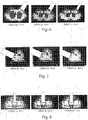
figure 3 shows a representation of the treated zone with conveyor; -
figure 4 shows a further representation of the treated zone with conveyor; -
figure 5 shows a simulation of a three-dimensional intraoperative distribution calculated using a statistical method; -
figure 6 shows a region, having a particular shape, treated by a conveyor; -
figure 7 shows a region having a further particular conformation, treated by a conveyor; -
figure 8 shows a region, having a further particular conformation, treated by a conveyor; -
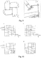
figure 9 shows a prototype of shaper of the beam, where figure A shows a view from below and figure B shows a side view; -
figure 10 shows a schematic representation of the algorithm used in the present invention; and -
figure 11 shows a block diagram of the algorithm. - In the various figures, similar parts will be indicated by the same reference numbers.
- Referring to
figure 1 , the system S includes a dedicated mobile electron accelerator A, an images acquisition apparatus B that allows the acquisition of the intra-operative images during surgery, different from the pre-operative ones, allowing the accurate localization of both the zone Z to be treated of the conveyor D for the delivery of the radiation. - System S also includes an integrated control unit E comprising a 2D and 3D images display and a computer that hosts a treatment planning program or "treatment planning system" (TPS), capable of interfacing with both the images display for image processing necessary for the calculation of the appropriate electron beam intensity and with accelerator A for the management of the specific radiotherapy activity and technical parameters.
- System S also comprises a control and verification device F based on an in vivo measurement performed in real time with small size active radiation detectors, such as diodes or MOSFET transistor, which interfaces with the integrated system E.
- The TPS program integrated with the accelerator A allows to acquire the images produced by the image display to be used intraoperatively for delineating regions of interest used as a guide during surgical intervention.
- System S allows to carry out a real time provisional study of the IORT plan, based on an accurate calculation resulting from processing the images, to calculate the intensity of the electron beam that can be sent to the zone Z to be treated and to the nearby tissues.
- TPS is based on the acquisition and elaboration of images, through appropriate computer codes for the co-registration of the images themselves, during pre-operative simulation of the treatment, intra-operative and post-operative.
- During the treatment pre-operative simulation, the TPS uses the characteristic dosimetric data of the accelerator A, such as percentage depth dose, called "Percentage Depth Dose" (PDD) and profiles for each energy value and to each type of conveyor D.
- The simulation also makes use of conveyors D geometry and the beam modifiers devices that are additional systems to be placed at the end of the conveyor D to shape the field.
- TPS algorithms uses Monte Carlo simulations and dosimetric experimental measurements under real conditions.
- TPS also includes calculation algorithms for the study of the interaction between the IORT electron beams and tissues of the patient passed through, aimed at calculating the intensity of the electrons beam emitted during intra-operative phase.
- TPS program also includes 3D anatomical segmentation models, which allows three dimensions visualization of organs and electronic intensity.
- In addition, system S provides data and information exchange between different devices, creating a dedicated unique platform performed using the standard DICOM images and proprietary standards with the accelerator A.
- System S has a function which differs according to the different phases in which it operates, in particular:
- in the data acquisition preliminary phase, "pre-planning", computed tomography (CT) images are acquired of the anatomical section C subject to surgery using any conventional CT imaging system.
- These images are then used for the realization and the optimization of the pre-operative treatment plan, calculating, by module TPS, a first intensity of the electron beam, taking into account the operating and geometric characteristic parameters of the electron accelerator A and/or calculated by the Monte Carlo method, to be delivered through the electron accelerator A in a first irradiation.
- During intraoperative phase, the image acquisition apparatus B acquires real-time three-dimensional/volumetric images post surgery that are sent to the TPS with the aim of determining the electron density of the tissues of the zone Z to be treated, in order to differentiate the effectiveness of treatment with respect to tumor tissue and to healthy organs.
- These data allow to calculate the distributions of the electron beam intensity also taking into account the presence of beam shapers or surfaces and/or volumes with irregular geometry and therefore to obtain, display and document the intensity distribution of the electron beam released to tissues during the IORT.
- Device F detects the real intensity of the first electrons beam in vivo delivered during the IORT treatment.
- This measure is compared with the value of the first intensity of the electron beam calculated and set before the treatment, so as then to modify/adapt the dose delivered in real time, avoiding possible undue doses, calculating a final intensity of the beam to be delivered in a second irradiation.
- Since the delivery of the IORT treatment is realized in two subsequent parts, a first radiation and a second radiation, according to a broken irradiation path, within the same surgical session, measurements made by the device F in vivo during the first part of delivery are used to optimize the delivery of the electron beam intensity during the second part.
- During the post-operative phase, TPS dosimetry calculations are supported by Monte Carlo simulation in order to verify the agreement with the dosimetry calculation of the TPS under realistic conditions, or using images and information acquired during the intra-operative phase.
- The electron beam intensity calculation refers to a database of dose distributions in water, calculated by Monte Carlo simulations or experimentally determined, in different reference geometries.
- As regards Monte Carlo simulations, the intensity distribution of the electron beam in water and the field magnitudes of the incident beam, derive from the totally detailed description and are characteristic of the IORT mobile linear accelerator used, both in geometry and construction materials terms.
- Starting from the distributions of the electron beam intensity in the water, the calculation execution choices are two. A first quick estimate of the electron beam intensity distribution, resulting from the geometry of irradiation choice, is obtained by selecting for each collimator (defined by diameter and cutting angle) and beam energy, the corresponding matrix of the beam intensity of electrons and applying a fast algorithm to compute the equivalent radiological path, such as "ray tracing".
- The data obtained through CT scans are used to determine the equivalent path in water through the calculation of known integrals for a specific radius through the regular arrangement in the CT space

- Indicating the voxel function as f(i, j, k), where voxel means a volumetric pixel, i.e. the voxels are considered as the intersection volume of sets of parallel planes and equally spaced, of indexes (i, j, k), and the length contained in that voxel as the l(i, j, k), the integral I above can be discretized according to the formula

- The direct calculation of this equation requires the use of an algorithm that scales with the number of terms in the sum, which corresponds to the number of voxels in the regular arrangement in CT space.
- Referring to
figure 10a , the pixels of the CT scan are considered as areas, defined by intersections of orthogonal sets of equally spaced parallel straight lines, , in particular two families of parallel straight lines, as shown infigure 10b . - The intersections of the radius AB are calculated, which represents the radiation, with the equally spaced parallel straight lines.
- As the lines are equally spaced, it is needed to determine only the first intersection and generate all the other recursively.
- The intersections of the radius AB with the straight lines, are given by the union of two equidistant sets, one set for horizontal straight lines (in solid line) and one for vertical straight lines (dashed).
- Referring, for example, to
figure 10a , the intersections between the radius AB and the straight lines consist of two groups, a first group for the intersections with the horizontal straight lines (triangles) and a second group for the intersections with the vertical straight lines (circles). - The intersections of the radius AB with the pixels are identified by the union of these two groups of intersections.
- The identification of this union set is used to determine the X-ray path.
- From this identification, the possibility of obtaining the regular arrangement in the CT three-dimensional space follows.
- The radius from point A to point B can be represented according to the known formulas:

- The parameter α, which defines the fraction of the path from A to B, is zero at point A and equal to one at point B.
- The intersections of radius AB with the sides of the regular arrangement of the voxels in the CT space are shown in
figure 10 . - Referring to
figure 11a , if both A and B points fall outside of the regular arrangement in CT space, then the parameter values corresponding to the intersection points of the radius with the edges are given by αmin and αmax. - All intersections of the radius AB with single lines must have parametric values that fall in the range between αmin and αmax.
- Referring to
figure 10b , the point A is within the regular arrangement in CT space and the value of αmin is zero. - Referring to
figure 10c , if point B is within the regular arrangement, then αmax is equal to one. - Referring to
figure 10d , in case of both points A and B are within the regular arrangement in CT space, αmin is equal to zero and αmax is equal to one. - The solution to the intersection of the radius with the CT voxels derives immediately as it corresponds to the parametric values of the intersections, in the range between αmin and αmax of the radius with each orthogonal set of parallel and equally spaced planes.
- For each of the coordinate planes, it is obtained a set of values of the parameter α and the three sets of parametric values are neatly combined in a single set; for example, by the combination of the ordered set (1, 4, 7); (2, 5, 8) and (3, 6, 9), the overall set (1, 2, 3, 4, 5, 6, 7, 8, 9) is obtained. The length of the beam contained by a particular voxel, in radius length units is given by the difference between two adjacent parametric values of the overall set.
- For each voxel intersection length, the indices of the corresponding voxel are obtained and the products of the length and density are summed over all the intersections for obtaining the radiological path. A more detailed description of the algorithm is given below.
- For a regular arrangement in the CT space of (Nx-1, Ny-1, Nz-1) voxel, the set of orthogonal equidistant parallel planes can be described using the following known formulas:


- The quantities dx, dy and dz also correspond to the lengths of the voxel sides.
- The parametric values αmin and αmax are obtained by the intersection of the radius AB and the sides of the regular arrangement in the CT space.
- From the above equations, the parametric values corresponding to the sides are obtained as follows:


- If the denominator (XB - XA) of the equation is zero, then the beam is perpendicular to the x-axis and the corresponding values of αx are undefined.
- The same applies to αy and αz.
- If the values of αx, αy or αz are undefined, then those values are simply dropped in all the following discussion.
- In terms of the parametric values given above, the quantities αmin and αmax are determined by the following known formulas:


- If αmax is less than or equal to αmin, then the radius does not intersect the regular arrangement in the CT space.
- Among all the intersecting planes, there are only a few that have parametric values in the range between αmin and αmax.
- From the above equations, the range of indices (imin, imax), (jmin, jmax) and (kmin, kmax), corresponding to these particular planes, are given by the following expressions:


- For a given range of indices (imin, imax), (jmin, jmax) and (kmin, kmax), the sets of parametric values {ax }, {ay } and {az }, corresponding to the intersections of the radius with the planes are given by the following expression:


- The sets {ax }, {ay } and {az } are each ordered in ascending order.
- Each term, in each set corresponds to the intersection of the radius with a particular plane. The intersections of the radius with the voxels are obtained grouping the set {ax }, {ay } and {az }, in one set.
- To include the case in which one or both of the extreme points of the radius can be within the regular arrangement in the CT space, the parametric values of αmin and αmax are added to the unique parametric set.
- The terms αmin and αmax and the grouped sets {ax }, {ay } and {az } are expressed by the set {α} according to the known formula:


- For two intersections m and m-1, the length l(m) of the voxel is given by the known expression:



- The voxel [i(m),j(m),k(m)] which corresponds to the intersections m and m-1 is the one that contains the middle point of the two intersections.
- The indices [i(m),j(m),k(m)] are obtained using the following known expressions:


- The integral I


- The algorithm can be modeled in the flow chart of
figure 11 . - For a typical problem, the relative time amount required by the computer processing, for each step of the algorithm, is reported in terms of the respective percentages, on the right of each descriptive block of the step at issue.
- This algorithm, applied to a data matrix of electronic densities, obtained from one or more imaging studies of the patient, extracts in each point the equivalent radiological path in water and uses it to sample inputs electron beam intensity matrix.
- The result of this sampling operation is then projected voxel by voxel, on a patient radiological image that represent the treatment studied.
- The images useful for the determination of the simulation of the dose are obtained in the phase of study/treatment planning, using a pre-surgery morphological image, the during surgery the previous image is suitably deformed and/or co-registered with the one acquired during surgery before IORT treatment.
- The calculation can also be carried out directly on the 3D image acquired in the operating room.
- A more accurate calculation of the dose is obtained by an analytical formula, by which Monte Carlo data are parameterized, whose parameters were obtained by statistical methods from the dose distribution obtained by Monte Carlo simulation, or alternatively by the experimental measures.
- Using this parameterization, the data calculated by Monte Carlo or measured are expressed in an integral analytical representation, applying the analytic fit formula from experimental data or by Monte Carlo.
- The percentage depth dose distribution along the central axis of the beam has been represented by means of the known formula:

and p 1...,p 5 are the parameters of the fit. - Furthermore, the distribution of percentage depth dose in the outer region to the conveyor is obtained by the original formula:

- The dose profile of the "pencil beam" radius is represented by a Gaussian which sigma varies with the depth in water and is separable into two
components 
- The analytical expression of the geometric component is given by


- The latter formula is the relevant part of the invention for the dose calculation.
- Experimental or generated by the Monte Carlo distributions, when they are managed in the form of "Look Up Tables" or of three-dimensional shape matrices g(i,j,l), are re-sampled to take into account the inhomogeneity encountered by the electrons in their path according to the scheme described below.
- Indicating with f(i,j,k) the electron beam intensity matrix and with k the index that identifies the depth in the medium crossed, it is

where g(i,j,l) is the original data matrix, ρl is the electron density relative to water and Δ z is the size of the voxel along the beam axis, i and j identify the start point of the path of the radiation of said zone (Z). - The information on the density obtained from the pre-surgery images of the patient, is used to modify the parameters of the analytical representation in order to describe more faithfully the effect on the electron beam intensity distribution by different densities encountered by the electron beam.
- The dosimetric on-line verification occurs by placing the dosimeter F in one or more points of interest within the surgical incision to be treated.
- The active dosimeter F (such as MOSFET, diodes, diamond) is made visible by the intra-operative imaging system (example with a radiopaque marker, hypoechoic, or other) and the reading value is used for comparison with the planned data.
- An advantage of the present invention is the possibility to calculate the intensity of the electron beam that can be sent to a zone to be treated to eliminate residual cancer cells, taking into account variations of the morphology of the zone to be treated as a result of surgery and of the radiation already received by the zone to be treated.
- A further advantage of the present invention is the possibility to take into account the presence of the beam modifiers dosimetric calculation, taking into account the absorption of the radiation in the same.
- The present invention has been described for illustrative but not limitative purposes, according to its preferred embodiments, but it is to be understood that modifications and/or changes can be introduced by those skilled in the art without departing from the relevant scope as defined in the enclosed claims.
Claims (5)
- System (S) for radiotherapy provided with a program for the calculation of the intensity of an electrons beam, the system comprising
a mobile electrons accelerator (A), equipped with a conveyor (D) adapted to convey an electrons beam with a presettable intensity on a zone (Z) of or internal to a patient, and constituting the target radiotherapy,
an images acquisition apparatus (B), adapted to detect said zone (Z),
an integrated control unit (E), comprising a bidimensional or tridimensional images display and a computer, said computer being connected to said electrons accelerator (A) and to said images acquisition apparatus (B), and
an active sensing device (F) of the radiation dose deposited by said electrons beam, that can be placed between the distal end of said conveyor (D) and said zone (Z), and that can be connected to said integrated control unit (E),
said computer being equipped with a program for the calculation of an intensity of said electrons beam by which said zone (Z) can be irradiated, comprising the following steps:(i) setting a first intensity of said electrons beam, according to functioning and geometric characteristic parameters of said electrons accelerator (A) and/or calculated by Monte Carlo method, and according to at least one predefined image of said zone (Z), said intensity being emitted by said electrons accelerator (A) in a first radiation;(ii) operating said electrons accelerator (A) to emit a first electrons beam in said first radiation, corresponding to a fraction of said first intensity set in said step (i);(iii) detecting a real intensity of said first electrons beam during said first radiation, by said radiation sensing device (F) placed in correspondence of said zone (Z);(iv) acquiring at least one image of said zone (Z) by said images acquisition apparatus (B);(v) calculating an intermediate intensity of said electrons beam, according to said at least one image acquired in said step (iv) and according to said real intensity of said first electrons beam detected in said step (iii); and(vi) comparing said first intensity of said step (i) with said intermediate intensity of said step (v) to calculate a final intensity of said electrons beam, by which said zone (Z) can be to irradiated in a second radiation following said first radiation.characterized in that the calculation of said final intensity of said step (vi) is performed by the following equation: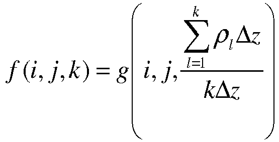
- System (S) according to claim 1, characterized in that the calculation of said function f(i,j,k) is performed by statistics simulation, for example of Monte Carlo type, carried out on reference data collected in a database of distribution of the intensity of an electrons beam in water, according to different reference geometries of said zone (Z) and constructive geometries of said mobile electrons accelerator (A).
- System (S) according to anyone of the preceding claims, characterized in that said portion emitted in said first radiation in said step (ii) corresponds to almost the half of said first intensity of said step (i), so as to provide the data necessary for the steps from (iv) to (vi).
- System (S) according to anyone of the preceding claims, characterized in that said steps from (i) to (iv) can be recursively run in such a way that, at each new recursion, the final intensity calculated in said step (iv) of the previous recursion coincides with a first intensity settable in said step (i) of the following recursion.
- System (S) according to anyone of the preceding claims, characterized in that said active radiation sensing device (F) is an active dosimeter, such as MOSFET or diode or diamond kind, and is equipped with a radiopaque or hypoechoic repere in order to be visible during said step (iv).
Applications Claiming Priority (2)
| Application Number | Priority Date | Filing Date | Title |
|---|---|---|---|
| IT000314A ITRM20130314A1 (en) | 2013-05-30 | 2013-05-30 | SYSTEM FOR RADIOTHERAPY PROVIDED WITH A PROGRAM FOR THE CALCULATION OF THE INTENSITY OF A BAND OF ELECTRONS. |
| PCT/IT2014/000147 WO2014192034A1 (en) | 2013-05-30 | 2014-05-28 | Radiotherapy system provided with a program for the calculation of the intensity of an electrons beam |
Publications (2)
| Publication Number | Publication Date |
|---|---|
| EP3003484A1 EP3003484A1 (en) | 2016-04-13 |
| EP3003484B1 true EP3003484B1 (en) | 2017-05-10 |
Family
ID=48877442
Family Applications (1)
| Application Number | Title | Priority Date | Filing Date |
|---|---|---|---|
| EP14748282.2A Active EP3003484B1 (en) | 2013-05-30 | 2014-05-28 | Radiotherapy system provided with a program for the calculation of the intensity of an electrons beam |
Country Status (6)
| Country | Link |
|---|---|
| US (1) | US10046176B2 (en) |
| EP (1) | EP3003484B1 (en) |
| ES (1) | ES2636765T3 (en) |
| IT (1) | ITRM20130314A1 (en) |
| RU (1) | RU2655070C2 (en) |
| WO (1) | WO2014192034A1 (en) |
Families Citing this family (2)
| Publication number | Priority date | Publication date | Assignee | Title |
|---|---|---|---|---|
| CN110353796A (en) * | 2018-04-28 | 2019-10-22 | 北京铭杰医疗科技有限公司 | Tumor treatment device and method of use thereof |
| DE102019118078B4 (en) * | 2019-07-04 | 2022-09-08 | Carl Zeiss Meditec Ag | Postoperative determination of the applied dose in the tumor tissue in IORT |
Family Cites Families (10)
| Publication number | Priority date | Publication date | Assignee | Title |
|---|---|---|---|---|
| JPS61231828A (en) | 1985-04-04 | 1986-10-16 | 三菱電機株式会社 | Gas insualted switchgear |
| RU2148827C1 (en) * | 1996-07-01 | 2000-05-10 | Кузбасский научно-исследовательский институт травматологии и реабилитации | Method for predicting repair process development course in burn wound |
| US7354391B2 (en) * | 2003-11-07 | 2008-04-08 | Cytyc Corporation | Implantable radiotherapy/brachytherapy radiation detecting apparatus and methods |
| EP1977788B1 (en) * | 2005-07-22 | 2011-05-04 | Tomotherapy Incorporated | System of delivering radiation therapy to a moving region of interest |
| US7839972B2 (en) * | 2005-07-22 | 2010-11-23 | Tomotherapy Incorporated | System and method of evaluating dose delivered by a radiation therapy system |
| US20090018403A1 (en) * | 2007-07-12 | 2009-01-15 | Sicel Technologies, Inc. | Trackable implantable sensor devices, systems, and related methods of operation |
| EP2269693A4 (en) * | 2008-04-14 | 2015-07-08 | Gmv Aerospace And Defence S A | INTRAOPERATIVE RADIOTHERAPY PLANNING SYSTEM AND METHOD FOR IMPLEMENTING SUCH PLANNING |
| WO2010141583A2 (en) * | 2009-06-02 | 2010-12-09 | Mayo Foundation For Medical Education And Research | System and method for dose verification radiotherapy |
| US8173983B1 (en) * | 2010-01-07 | 2012-05-08 | Velayudhan Sahadevan | All field simultaneous radiation therapy |
| CN103096975B (en) * | 2010-09-09 | 2016-10-26 | 皇家飞利浦电子股份有限公司 | Dosimeter, treatment device and computer system for measuring radiation dose to a subject during magnetic resonance imaging |
-
2013
- 2013-05-30 IT IT000314A patent/ITRM20130314A1/en unknown
-
2014
- 2014-05-28 RU RU2015151193A patent/RU2655070C2/en active
- 2014-05-28 WO PCT/IT2014/000147 patent/WO2014192034A1/en not_active Ceased
- 2014-05-28 ES ES14748282.2T patent/ES2636765T3/en active Active
- 2014-05-28 EP EP14748282.2A patent/EP3003484B1/en active Active
- 2014-05-28 US US14/894,472 patent/US10046176B2/en active Active
Also Published As
| Publication number | Publication date |
|---|---|
| EP3003484A1 (en) | 2016-04-13 |
| RU2015151193A3 (en) | 2018-03-26 |
| US20160121137A1 (en) | 2016-05-05 |
| ES2636765T3 (en) | 2017-10-09 |
| RU2655070C2 (en) | 2018-05-23 |
| WO2014192034A1 (en) | 2014-12-04 |
| ITRM20130314A1 (en) | 2014-12-01 |
| RU2015151193A (en) | 2017-07-06 |
| US10046176B2 (en) | 2018-08-14 |
Similar Documents
| Publication | Publication Date | Title |
|---|---|---|
| Verhaegen et al. | A review of treatment planning for precision image-guided photon beam pre-clinical animal radiation studies | |
| US9463336B2 (en) | Benchmark system for radiation therapy planning | |
| US9076222B2 (en) | Use of collection of plans to develop new optimization objectives | |
| CN106237545B (en) | a radiotherapy device | |
| US11426606B2 (en) | Method and system of evaluating a radiation therapy treatment plan | |
| KR20100016039A (en) | Improved treatment plan evaluation in radiotherapy by stochastic analysis of delineation uncertainty | |
| CA2568343A1 (en) | Systems and methods for global optimization of treatment planning for external beam radiation therapy | |
| EP2269693A1 (en) | Planning system for intraoperative radiation therapy and method for carrying out said planning | |
| DeJongh et al. | A comparison of proton stopping power measured with proton CT and x‐ray CT in fresh postmortem porcine structures | |
| CN106237523A (en) | Improvement for radiotherapeutic dosimetry technical elements | |
| Steinsberger et al. | Extension of RBE-weighted 4D particle dose calculation for non-periodic motion | |
| Sloboda et al. | A brief look at model-based dose calculation principles, practicalities, and promise | |
| Sait et al. | Validation of three-dimensional electronic portal imaging device-based PerFRACTION™ software for patient-specific quality assurance | |
| US10046176B2 (en) | Radiotherapy system provided with a program for the calculation of the intensity of an electrons beam | |
| JP6312737B2 (en) | Method for generating and / or providing data for tissue treatment | |
| Gayol et al. | MRI-LINAC dosimetry approach by Monte Carlo codes coupling charged particle radiation transport with strong magnetic fields | |
| Sevcik et al. | Low energy deposition patterns in irradiated phantom with metal artefacts inside: a comparison between FLUKA Monte Carlo simulation and GafChromic EBT2 film measurements | |
| Jannah et al. | Evaluation of doses distribution in breast cancer mastectomy using SlicerRT | |
| Bertschi | Towards the application of prompt-gamma imaging in online adaptive proton therapy | |
| Bentefour et al. | Using CBCT for pretreatment range check in proton therapy: a phantom study for prostate treatment by anterior–posterior beam | |
| Fernandes | Proton Range Verification for Irradiation of Anthropomorphic Phantoms Implemented in Geant4 Monte Carlo Simulations | |
| Kititharakun et al. | Surrounding dose investigation of real-time motion tracking system in tomotherapy | |
| Paruccini et al. | [OA211] A single phantom, a single statistical method, a single figure of merit for all X-ray equipment | |
| KR101297263B1 (en) | Simulation apparatus for radiation dose of charged particle, irradiation apparatus for charged particle ray, simulation apparatus for radiation dose of charged particle, and irradiation method for charged particle ray | |
| JP2023157681A (en) | Treatment planning system, treatment planning method and treatment planning program |
Legal Events
| Date | Code | Title | Description |
|---|---|---|---|
| PUAI | Public reference made under article 153(3) epc to a published international application that has entered the european phase |
Free format text: ORIGINAL CODE: 0009012 |
|
| 17P | Request for examination filed |
Effective date: 20151215 |
|
| AK | Designated contracting states |
Kind code of ref document: A1 Designated state(s): AL AT BE BG CH CY CZ DE DK EE ES FI FR GB GR HR HU IE IS IT LI LT LU LV MC MK MT NL NO PL PT RO RS SE SI SK SM TR |
|
| AX | Request for extension of the european patent |
Extension state: BA ME |
|
| DAX | Request for extension of the european patent (deleted) | ||
| GRAP | Despatch of communication of intention to grant a patent |
Free format text: ORIGINAL CODE: EPIDOSNIGR1 |
|
| INTG | Intention to grant announced |
Effective date: 20161202 |
|
| GRAS | Grant fee paid |
Free format text: ORIGINAL CODE: EPIDOSNIGR3 |
|
| GRAA | (expected) grant |
Free format text: ORIGINAL CODE: 0009210 |
|
| AK | Designated contracting states |
Kind code of ref document: B1 Designated state(s): AL AT BE BG CH CY CZ DE DK EE ES FI FR GB GR HR HU IE IS IT LI LT LU LV MC MK MT NL NO PL PT RO RS SE SI SK SM TR |
|
| REG | Reference to a national code |
Ref country code: GB Ref legal event code: FG4D |
|
| REG | Reference to a national code |
Ref country code: AT Ref legal event code: REF Ref document number: 891674 Country of ref document: AT Kind code of ref document: T Effective date: 20170515 Ref country code: CH Ref legal event code: EP |
|
| REG | Reference to a national code |
Ref country code: IE Ref legal event code: FG4D |
|
| REG | Reference to a national code |
Ref country code: DE Ref legal event code: R096 Ref document number: 602014009759 Country of ref document: DE |
|
| REG | Reference to a national code |
Ref country code: FR Ref legal event code: PLFP Year of fee payment: 4 |
|
| REG | Reference to a national code |
Ref country code: NL Ref legal event code: MP Effective date: 20170510 |
|
| REG | Reference to a national code |
Ref country code: LT Ref legal event code: MG4D |
|
| REG | Reference to a national code |
Ref country code: ES Ref legal event code: FG2A Ref document number: 2636765 Country of ref document: ES Kind code of ref document: T3 Effective date: 20171009 |
|
| REG | Reference to a national code |
Ref country code: AT Ref legal event code: MK05 Ref document number: 891674 Country of ref document: AT Kind code of ref document: T Effective date: 20170510 |
|
| PG25 | Lapsed in a contracting state [announced via postgrant information from national office to epo] |
Ref country code: NO Free format text: LAPSE BECAUSE OF FAILURE TO SUBMIT A TRANSLATION OF THE DESCRIPTION OR TO PAY THE FEE WITHIN THE PRESCRIBED TIME-LIMIT Effective date: 20170810 Ref country code: GR Free format text: LAPSE BECAUSE OF FAILURE TO SUBMIT A TRANSLATION OF THE DESCRIPTION OR TO PAY THE FEE WITHIN THE PRESCRIBED TIME-LIMIT Effective date: 20170811 Ref country code: HR Free format text: LAPSE BECAUSE OF FAILURE TO SUBMIT A TRANSLATION OF THE DESCRIPTION OR TO PAY THE FEE WITHIN THE PRESCRIBED TIME-LIMIT Effective date: 20170510 Ref country code: LT Free format text: LAPSE BECAUSE OF FAILURE TO SUBMIT A TRANSLATION OF THE DESCRIPTION OR TO PAY THE FEE WITHIN THE PRESCRIBED TIME-LIMIT Effective date: 20170510 Ref country code: AT Free format text: LAPSE BECAUSE OF FAILURE TO SUBMIT A TRANSLATION OF THE DESCRIPTION OR TO PAY THE FEE WITHIN THE PRESCRIBED TIME-LIMIT Effective date: 20170510 Ref country code: FI Free format text: LAPSE BECAUSE OF FAILURE TO SUBMIT A TRANSLATION OF THE DESCRIPTION OR TO PAY THE FEE WITHIN THE PRESCRIBED TIME-LIMIT Effective date: 20170510 |
|
| PG25 | Lapsed in a contracting state [announced via postgrant information from national office to epo] |
Ref country code: SE Free format text: LAPSE BECAUSE OF FAILURE TO SUBMIT A TRANSLATION OF THE DESCRIPTION OR TO PAY THE FEE WITHIN THE PRESCRIBED TIME-LIMIT Effective date: 20170510 Ref country code: LV Free format text: LAPSE BECAUSE OF FAILURE TO SUBMIT A TRANSLATION OF THE DESCRIPTION OR TO PAY THE FEE WITHIN THE PRESCRIBED TIME-LIMIT Effective date: 20170510 Ref country code: RS Free format text: LAPSE BECAUSE OF FAILURE TO SUBMIT A TRANSLATION OF THE DESCRIPTION OR TO PAY THE FEE WITHIN THE PRESCRIBED TIME-LIMIT Effective date: 20170510 Ref country code: PL Free format text: LAPSE BECAUSE OF FAILURE TO SUBMIT A TRANSLATION OF THE DESCRIPTION OR TO PAY THE FEE WITHIN THE PRESCRIBED TIME-LIMIT Effective date: 20170510 Ref country code: NL Free format text: LAPSE BECAUSE OF FAILURE TO SUBMIT A TRANSLATION OF THE DESCRIPTION OR TO PAY THE FEE WITHIN THE PRESCRIBED TIME-LIMIT Effective date: 20170510 Ref country code: BG Free format text: LAPSE BECAUSE OF FAILURE TO SUBMIT A TRANSLATION OF THE DESCRIPTION OR TO PAY THE FEE WITHIN THE PRESCRIBED TIME-LIMIT Effective date: 20170810 Ref country code: IS Free format text: LAPSE BECAUSE OF FAILURE TO SUBMIT A TRANSLATION OF THE DESCRIPTION OR TO PAY THE FEE WITHIN THE PRESCRIBED TIME-LIMIT Effective date: 20170910 |
|
| REG | Reference to a national code |
Ref country code: CH Ref legal event code: PL |
|
| PG25 | Lapsed in a contracting state [announced via postgrant information from national office to epo] |
Ref country code: DK Free format text: LAPSE BECAUSE OF FAILURE TO SUBMIT A TRANSLATION OF THE DESCRIPTION OR TO PAY THE FEE WITHIN THE PRESCRIBED TIME-LIMIT Effective date: 20170510 Ref country code: EE Free format text: LAPSE BECAUSE OF FAILURE TO SUBMIT A TRANSLATION OF THE DESCRIPTION OR TO PAY THE FEE WITHIN THE PRESCRIBED TIME-LIMIT Effective date: 20170510 Ref country code: RO Free format text: LAPSE BECAUSE OF FAILURE TO SUBMIT A TRANSLATION OF THE DESCRIPTION OR TO PAY THE FEE WITHIN THE PRESCRIBED TIME-LIMIT Effective date: 20170510 Ref country code: CZ Free format text: LAPSE BECAUSE OF FAILURE TO SUBMIT A TRANSLATION OF THE DESCRIPTION OR TO PAY THE FEE WITHIN THE PRESCRIBED TIME-LIMIT Effective date: 20170510 Ref country code: SK Free format text: LAPSE BECAUSE OF FAILURE TO SUBMIT A TRANSLATION OF THE DESCRIPTION OR TO PAY THE FEE WITHIN THE PRESCRIBED TIME-LIMIT Effective date: 20170510 |
|
| REG | Reference to a national code |
Ref country code: DE Ref legal event code: R097 Ref document number: 602014009759 Country of ref document: DE |
|
| REG | Reference to a national code |
Ref country code: IE Ref legal event code: MM4A |
|
| PG25 | Lapsed in a contracting state [announced via postgrant information from national office to epo] |
Ref country code: CH Free format text: LAPSE BECAUSE OF NON-PAYMENT OF DUE FEES Effective date: 20170531 Ref country code: LI Free format text: LAPSE BECAUSE OF NON-PAYMENT OF DUE FEES Effective date: 20170531 Ref country code: SM Free format text: LAPSE BECAUSE OF FAILURE TO SUBMIT A TRANSLATION OF THE DESCRIPTION OR TO PAY THE FEE WITHIN THE PRESCRIBED TIME-LIMIT Effective date: 20170510 Ref country code: IT Free format text: LAPSE BECAUSE OF FAILURE TO SUBMIT A TRANSLATION OF THE DESCRIPTION OR TO PAY THE FEE WITHIN THE PRESCRIBED TIME-LIMIT Effective date: 20170510 |
|
| PLBE | No opposition filed within time limit |
Free format text: ORIGINAL CODE: 0009261 |
|
| STAA | Information on the status of an ep patent application or granted ep patent |
Free format text: STATUS: NO OPPOSITION FILED WITHIN TIME LIMIT |
|
| PG25 | Lapsed in a contracting state [announced via postgrant information from national office to epo] |
Ref country code: LU Free format text: LAPSE BECAUSE OF NON-PAYMENT OF DUE FEES Effective date: 20170528 |
|
| REG | Reference to a national code |
Ref country code: FR Ref legal event code: PLFP Year of fee payment: 5 |
|
| 26N | No opposition filed |
Effective date: 20180213 |
|
| REG | Reference to a national code |
Ref country code: BE Ref legal event code: MM Effective date: 20170531 |
|
| PG25 | Lapsed in a contracting state [announced via postgrant information from national office to epo] |
Ref country code: IE Free format text: LAPSE BECAUSE OF NON-PAYMENT OF DUE FEES Effective date: 20170528 |
|
| PG25 | Lapsed in a contracting state [announced via postgrant information from national office to epo] |
Ref country code: SI Free format text: LAPSE BECAUSE OF FAILURE TO SUBMIT A TRANSLATION OF THE DESCRIPTION OR TO PAY THE FEE WITHIN THE PRESCRIBED TIME-LIMIT Effective date: 20170510 |
|
| PG25 | Lapsed in a contracting state [announced via postgrant information from national office to epo] |
Ref country code: BE Free format text: LAPSE BECAUSE OF NON-PAYMENT OF DUE FEES Effective date: 20170531 |
|
| PG25 | Lapsed in a contracting state [announced via postgrant information from national office to epo] |
Ref country code: MT Free format text: LAPSE BECAUSE OF NON-PAYMENT OF DUE FEES Effective date: 20170528 |
|
| GBPC | Gb: european patent ceased through non-payment of renewal fee |
Effective date: 20180528 |
|
| PG25 | Lapsed in a contracting state [announced via postgrant information from national office to epo] |
Ref country code: GB Free format text: LAPSE BECAUSE OF NON-PAYMENT OF DUE FEES Effective date: 20180528 |
|
| PG25 | Lapsed in a contracting state [announced via postgrant information from national office to epo] |
Ref country code: MC Free format text: LAPSE BECAUSE OF FAILURE TO SUBMIT A TRANSLATION OF THE DESCRIPTION OR TO PAY THE FEE WITHIN THE PRESCRIBED TIME-LIMIT Effective date: 20170510 Ref country code: HU Free format text: LAPSE BECAUSE OF FAILURE TO SUBMIT A TRANSLATION OF THE DESCRIPTION OR TO PAY THE FEE WITHIN THE PRESCRIBED TIME-LIMIT; INVALID AB INITIO Effective date: 20140528 |
|
| PG25 | Lapsed in a contracting state [announced via postgrant information from national office to epo] |
Ref country code: CY Free format text: LAPSE BECAUSE OF FAILURE TO SUBMIT A TRANSLATION OF THE DESCRIPTION OR TO PAY THE FEE WITHIN THE PRESCRIBED TIME-LIMIT Effective date: 20170510 |
|
| PG25 | Lapsed in a contracting state [announced via postgrant information from national office to epo] |
Ref country code: MK Free format text: LAPSE BECAUSE OF FAILURE TO SUBMIT A TRANSLATION OF THE DESCRIPTION OR TO PAY THE FEE WITHIN THE PRESCRIBED TIME-LIMIT Effective date: 20170510 |
|
| PG25 | Lapsed in a contracting state [announced via postgrant information from national office to epo] |
Ref country code: TR Free format text: LAPSE BECAUSE OF FAILURE TO SUBMIT A TRANSLATION OF THE DESCRIPTION OR TO PAY THE FEE WITHIN THE PRESCRIBED TIME-LIMIT Effective date: 20170510 |
|
| PG25 | Lapsed in a contracting state [announced via postgrant information from national office to epo] |
Ref country code: PT Free format text: LAPSE BECAUSE OF FAILURE TO SUBMIT A TRANSLATION OF THE DESCRIPTION OR TO PAY THE FEE WITHIN THE PRESCRIBED TIME-LIMIT Effective date: 20170510 |
|
| PG25 | Lapsed in a contracting state [announced via postgrant information from national office to epo] |
Ref country code: AL Free format text: LAPSE BECAUSE OF FAILURE TO SUBMIT A TRANSLATION OF THE DESCRIPTION OR TO PAY THE FEE WITHIN THE PRESCRIBED TIME-LIMIT Effective date: 20170510 |
|
| REG | Reference to a national code |
Ref country code: FR Ref legal event code: PLFP Year of fee payment: 10 |
|
| P01 | Opt-out of the competence of the unified patent court (upc) registered |
Effective date: 20230616 |
|
| PGFP | Annual fee paid to national office [announced via postgrant information from national office to epo] |
Ref country code: FR Payment date: 20240328 Year of fee payment: 11 |
|
| PGFP | Annual fee paid to national office [announced via postgrant information from national office to epo] |
Ref country code: DE Payment date: 20240328 Year of fee payment: 11 |
|
| PGFP | Annual fee paid to national office [announced via postgrant information from national office to epo] |
Ref country code: ES Payment date: 20240610 Year of fee payment: 11 |
|
| REG | Reference to a national code |
Ref country code: DE Ref legal event code: R119 Ref document number: 602014009759 Country of ref document: DE |
|
| PG25 | Lapsed in a contracting state [announced via postgrant information from national office to epo] |
Ref country code: DE Free format text: LAPSE BECAUSE OF NON-PAYMENT OF DUE FEES Effective date: 20251202 |
|
| PG25 | Lapsed in a contracting state [announced via postgrant information from national office to epo] |
Ref country code: FR Free format text: LAPSE BECAUSE OF NON-PAYMENT OF DUE FEES Effective date: 20250531 |