EP3002974A1 - Communication system and communication method, communication apparatus and control method for the same, program, and storage medium - Google Patents
Communication system and communication method, communication apparatus and control method for the same, program, and storage medium Download PDFInfo
- Publication number
- EP3002974A1 EP3002974A1 EP15184278.8A EP15184278A EP3002974A1 EP 3002974 A1 EP3002974 A1 EP 3002974A1 EP 15184278 A EP15184278 A EP 15184278A EP 3002974 A1 EP3002974 A1 EP 3002974A1
- Authority
- EP
- European Patent Office
- Prior art keywords
- communication apparatus
- information
- communication
- signal
- network
- Prior art date
- Legal status (The legal status is an assumption and is not a legal conclusion. Google has not performed a legal analysis and makes no representation as to the accuracy of the status listed.)
- Granted
Links
- 238000004891 communication Methods 0.000 title claims abstract description 217
- 238000000034 method Methods 0.000 title claims description 31
- 230000004044 response Effects 0.000 claims abstract description 11
- 230000000737 periodic effect Effects 0.000 claims description 4
- 230000008054 signal transmission Effects 0.000 claims 2
- 230000006870 function Effects 0.000 description 45
- 230000008569 process Effects 0.000 description 17
- 238000010586 diagram Methods 0.000 description 12
- 230000005540 biological transmission Effects 0.000 description 8
- 238000005516 engineering process Methods 0.000 description 5
- 238000001514 detection method Methods 0.000 description 3
- 230000007704 transition Effects 0.000 description 3
- 230000010267 cellular communication Effects 0.000 description 2
- 230000001960 triggered effect Effects 0.000 description 2
- 230000004913 activation Effects 0.000 description 1
- 230000009286 beneficial effect Effects 0.000 description 1
- 230000001413 cellular effect Effects 0.000 description 1
- 125000004122 cyclic group Chemical group 0.000 description 1
- 230000014509 gene expression Effects 0.000 description 1
- 238000010295 mobile communication Methods 0.000 description 1
- 238000012986 modification Methods 0.000 description 1
- 230000004048 modification Effects 0.000 description 1
- 230000003287 optical effect Effects 0.000 description 1
- 230000009467 reduction Effects 0.000 description 1
Images


Classifications
-
- H—ELECTRICITY
- H04—ELECTRIC COMMUNICATION TECHNIQUE
- H04W—WIRELESS COMMUNICATION NETWORKS
- H04W72/00—Local resource management
- H04W72/50—Allocation or scheduling criteria for wireless resources
- H04W72/51—Allocation or scheduling criteria for wireless resources based on terminal or device properties
-
- H—ELECTRICITY
- H04—ELECTRIC COMMUNICATION TECHNIQUE
- H04W—WIRELESS COMMUNICATION NETWORKS
- H04W4/00—Services specially adapted for wireless communication networks; Facilities therefor
- H04W4/70—Services for machine-to-machine communication [M2M] or machine type communication [MTC]
-
- H—ELECTRICITY
- H04—ELECTRIC COMMUNICATION TECHNIQUE
- H04W—WIRELESS COMMUNICATION NETWORKS
- H04W4/00—Services specially adapted for wireless communication networks; Facilities therefor
- H04W4/80—Services using short range communication, e.g. near-field communication [NFC], radio-frequency identification [RFID] or low energy communication
-
- H—ELECTRICITY
- H04—ELECTRIC COMMUNICATION TECHNIQUE
- H04W—WIRELESS COMMUNICATION NETWORKS
- H04W48/00—Access restriction; Network selection; Access point selection
-
- H—ELECTRICITY
- H04—ELECTRIC COMMUNICATION TECHNIQUE
- H04W—WIRELESS COMMUNICATION NETWORKS
- H04W76/00—Connection management
- H04W76/10—Connection setup
-
- H—ELECTRICITY
- H04—ELECTRIC COMMUNICATION TECHNIQUE
- H04W—WIRELESS COMMUNICATION NETWORKS
- H04W84/00—Network topologies
- H04W84/02—Hierarchically pre-organised networks, e.g. paging networks, cellular networks, WLAN [Wireless Local Area Network] or WLL [Wireless Local Loop]
- H04W84/10—Small scale networks; Flat hierarchical networks
- H04W84/12—WLAN [Wireless Local Area Networks]
-
- H—ELECTRICITY
- H04—ELECTRIC COMMUNICATION TECHNIQUE
- H04W—WIRELESS COMMUNICATION NETWORKS
- H04W84/00—Network topologies
- H04W84/18—Self-organising networks, e.g. ad-hoc networks or sensor networks
Definitions
- the present invention relates to communication setting technology for wireless communication.
- a digital camera In recent years, an increasing number of products such as digital cameras are equipped with a communication function that uses a wireless local area network (LAN). Consequently, using the communication function, a digital camera, for example, is capable of uploading a captured image to a server on the Internet so that a plurality of users can share the captured image.
- a wireless local area network LAN
- the user of the camera needs to perform an operation to connect the camera to one of the access points (APs) of the wireless LAN that are located in the proximity of the camera.
- APs access points
- the user of the camera needs to input the identifier of an AP, or connection parameters including security system information, a password, etc., to the camera, and cause the camera to start connecting to the AP, in a location where the camera can communicate with the AP.
- NFC near field communication
- BLE Bluetooth ® low energy
- Smartphones have a user interface that is suitable for inputting characters, and in general, inputting connection parameters from these devices is easier than performing similar inputting from cameras in many cases. Furthermore, many smartphones have the function of automatically finding and connecting to a connectable AP by using, for example, connection parameters obtained by reading a QR code (TM), or connection parameters input in the past. However, it is not easy to equip cameras with a function that is similar to the function of smartphones for reasons such as the cost, size, etc.
- QR code QR code
- Japanese Patent Laid-open No. 2010-245748 discloses a technology by which a terminal device that is connected to an AP transmits the connection parameters for the AP to a camera by NFC, and the camera connects to the same AP. Note that equipping a camera with such a function does not greatly influence the cost, size, etc., of the camera because the only function to be added to the camera is the NFC communication function.
- the present invention is made in view of the above problem, and in a communication system including a plurality of apparatuses among which information used for connecting to another apparatus is exchanged, the present invention provides a technology for improving user convenience when the information used for the connection is exchanged.
- the present invention in its first aspect provides a communication system as specified in claim 1.
- the present invention in its second aspect provides a communication apparatus as specified in claims 2 to 10.
- the present invention in its third aspect provides a communication method as specified in claim 11.
- the present invention in its fourth aspect provides a communication apparatus control method as specified in claim 12.
- the present invention in its fifth aspect provides a program as specified in claim 13.
- the present invention in its sixth aspect provides a storage medium as specified in claim 14.
- FIG. 1 shows an example of the configuration of a wireless communication system according to the present embodiment.
- a camera 100 uploads captured image data to a server 103 on a network (e.g. the Internet) via an access point (AP) 102 of a wireless LAN.
- the camera 100 obtains AP information, which is for connecting to the AP 102, from a smartphone 101 by wireless communication that is based on the Bluetooth low energy (BLE) communication standard.
- the AP information includes, for example, information indicating that the AP 102 is present in the proximity of the smartphone 101 at the timing when the AP information is transmitted, and connection parameters used for connecting to the AP 102.
- connection parameters include, for example, the AP identifier of the AP 102, information indicating the security system type of the AP 102, and password information required to connect to the AP 102 by using the security system.
- An AP identifier is, for example, the identifier that identifies an AP, or the identifier of a wireless LAN network formed by an AP, and a service set identifier (SSID) or the like may be used as an AP identifier.
- SSID service set identifier Serving as a terminal in the wireless LAN, the camera 100 connects to the AP 102 based on the AP information.
- the camera 100 and the smartphone 101 that perform communication for establishing a wireless LAN connection between the camera 100 and the AP 102, but these are merely examples, and other devices having the communication function may be used.
- the following accounts apply to, in general terms, any system in which a first communication apparatus and a second communication apparatus perform communication for establishing a connection between the first communication apparatus and a third communication apparatus.
- the "third communication apparatus" mentioned above is not necessarily a particular communication apparatus, and may be any communication apparatus that can connect to the server 103 on the network.
- the third communication apparatus may be, for example, an access point of a wireless LAN that is connected to a wired network and establishes a wireless network, or a communication apparatus that is capable of connecting to a network for wirelessly connecting to the server 103.
- the camera 100 and the smartphone 101 perform communication by BLE and communication between the camera 100 or the smartphone 101 and the AP 102 is performed via a wireless LAN
- the camera 100 or the smartphone 101 and the AP 102 may perform communication with each other via a wireless network that uses a method other than the wireless LAN method
- the camera 100 and the smartphone 101 may perform communication with each other by using a method other than the BLE method.
- the wireless LAN to be used may be a wireless LAN complying with the series of IEEE 802.11 standards for example, or any of the past, present, or future wireless LANs.
- other communication methods to be used may be any of the past, present, or future methods.
- FIG. 2 is a sequence diagram showing an example of the flow of BLE communication performed by the camera 100 and the smartphone 101.
- the camera 100 repeatedly and periodically transmits an advertising packet at predetermined intervals.
- the advertising packet mentioned here is, for example, a packet used for finding the other party performing BLE communication, in order to obtain the AP information that is necessary for the camera 100 to connect to another communication apparatus (e.g. the AP 102) that is used for connecting to a network.
- the smartphone 101 Upon receiving the advertising packet from the camera 100, the smartphone 101 transmits a connection request to the camera 100.
- a BLE communication connection is established between the camera 100 and the smartphone 101, and thereafter a transition to intermittent communication occurs, by which data packets are periodically exchanged at predetermined intervals.
- the camera 100 needs to obtain from the smartphone 101 information about the timing of starting intermittent communication, and information about the intervals of the intermittent communication, and these pieces of information are contained in the connection request packet.
- the camera 100 and the smartphone 101 exchange data packets at the intervals of the intermittent communication.
- the communication apparatus on the transmission side transmits information indicating whether or not data to be transmitted is contained in the data packet by including the information in the data packet, and the communication apparatus on the reception side can determine whether or not the packet includes significant data by checking the information.
- the camera 100 When it is necessary to connect to the AP 102 (connect to the network), the camera 100 requests the smartphone 101 for the AP information by using the data packet for the subsequent sequence of intermittent communication.
- the AP information requested here is not necessarily the information of the particular AP 102, and may be information of any AP that can connect to the network. Therefore, this request for the AP information can be regarded as a signal indicating that the camera 100 wishes to connect to the network.
- the data packet in this case can be regarded as a signal for notifying the smartphone 101 that the camera 100 wishes to connect to the network.
- the smartphone 101 After receiving this request, upon detecting that an AP (e.g. the AP 102) that can connect to the network is present in the proximity, the smartphone 101 transmits the AP information of the AP by using the data packet for the sequence of intermittent communication that is subsequent to the timing of detection.
- AP e.g. the AP 102
- the smartphone 101 transmits the AP information of the AP by using the data packet for the sequence of intermittent communication that is subsequent to the timing of detection.
- “proximity” mentioned here is the communicable range for the smartphone 101 via the wireless LAN.
- this AP information includes, for example, information indicating that the AP 102 is present in the proximity of the smartphone 101 at the timing when the AP information is transmitted, and connection parameters used for connecting to the AP 102.
- the communicable range of BLE communication has a sufficiently short distance
- the camera 100 which is the communication partner to the smartphone 101 by BLE communication, is also present in the proximity of the AP 102. Therefore, by being notified that the smartphone 101 has detected the AP 102 in its proximity, and being provided with the AP information of the AP 102, the camera 100 can connect to the AP 102, and can connect to, for example, the server 103 via the AP 102.
- the intervals of intermittent communication may be set with consideration of the movement of the smartphone 101, and may be set to approximately 1 second, for example.
- the smartphone 101 has ordinary functions required to obtain the AP identifiers of APs in its proximity.
- the smartphone 101 has, for example, the function of obtaining the AP identifiers by performing a passive scan prescribed by the wireless LAN standard, and receiving a beacon that is periodically transmitted from each AP in its proximity.
- the smartphone 101 has a user interface, from which the user makes an instruction to perform a passive scan.
- the smartphone 101 may have the function of automatically performing a scan, instead of the user interface, or in addition to the user interface.
- the smartphone 101 may have the function of automatically performing a scan when it is in a location where an AP is likely to be present, by using positional information.
- the smartphone 101 has ordinary functions required to obtain the connection parameters other than the AP identifier as well, with respect to one AP out of the APs in its proximity.
- the smartphone 101 has, for example, the function of displaying a list of the AP identifiers found by a passive scan, and an acceptance function, which is the function of allowing the user to select one of the AP identifiers and accepting user input of the security system and password corresponding to the selected AP.
- the acceptance function may be, for example, a software or hardware keyboard function, or the function of capturing and analyzing a QR code or the like.
- the smartphone 101 may have the function of storing input content accepted in the past so that thereafter input of the same content by the user can be avoided.
- FIG. 3 is a block diagram showing an example of the functional configuration of the camera 100.
- the camera 100 includes, for example, a wireless LAN communication unit 301, a BLE communication unit 302, an AP information requesting unit 303, an image storing unit 304, and an image capturing unit 305.
- functions not related to the present embodiment, such as a calling function, are not depicted in the drawing, and their description has been omitted.
- the wireless LAN communication unit 301 includes, for example, an ordinary antenna, a modulation and demodulation function, and a protocol processing function, which are required for wireless LAN communication, and the wireless LAN communication unit 301 connects to the AP 102, reads out image data stored in the image storing unit 304 for example, and transmits it to the AP 102. Note that the image data transmitted to the AP 102 is transferred to the server 103, via a network for example.
- the BLE communication unit 302 includes, for example, an ordinary antenna, a modulation and demodulation function, and a protocol processing function, which are required for BLE communication, and, as described above, the BLE communication unit 302 establishes a connection with the smartphone 101 by BLE communication and performs intermittent communication with the smartphone 101.
- the AP information requesting unit 303 obtains the AP information from the smartphone 101 by using the BLE communication unit 302, and, based on the AP information, outputs the timing at which the wireless LAN communication unit 301 connects to the AP 102, and the connection parameters for the AP 102, to the wireless LAN communication unit 301.
- the wireless LAN communication unit 301 connects to the AP 102 according to these pieces of information.
- the image storing unit 304 stores, for example, image data captured by the image capturing unit 305.
- the image capturing unit 305 performs image capturing according to a user operation, generates image data, and stores it to the image storing unit 304.
- the image storing unit 304 can store the image data of not only one image, but of a plurality of images.
- the camera 100 may have, for example, hardware modules constituting at least one CPU, at least one ROM, at least one RAM, and so on, which are not shown in FIG. 3 , and the CPU may perform the processes represented by the flowchart described below by executing a program stored in the ROM.
- FIG. 4 shows the flow of the processes performed in the camera 100, particularly by the AP information requesting unit 303.
- the AP information requesting unit 303 starts its operation when triggered by the turning on of the power of the camera.
- the AP information requesting unit 303 repeatedly transmits the advertising packet at predetermined intervals by using the BLE communication unit 302 (step S401), and starts periodically transmitting/receiving signals via intermittent communication in response to receiving a connection request from the smartphone 101 (step S402).
- the AP information requesting unit 303 determines whether or not there is any data to be transmitted to the server 103 (step S403).
- the data to be transmitted to the server may be, for example, image data in the image storing unit 304, which has not been transmitted yet, or image data specified by the user.
- the AP information requesting unit 303 controls the BLE communication unit 302 to transmit the AP information request by using the data packet for the subsequent sequence of the intermittent communication (step S404). Then, the AP information requesting unit 303 waits to receive the AP information from the smartphone 101 via a subsequent sequence of the intermittent communication (step S405).
- the AP information requesting unit 303 controls the wireless LAN communication unit 301 so that it connects to the AP 102 by using the connection parameters contained in the AP information thus received, thereby connecting the camera 100 to the AP 102 (step S406).
- the AP information requesting unit 303 controls the wireless LAN communication unit 301 so that it transmits the data to be transmitted, which has been determined in step S403, to the server 103 via the AP 102 (step S407).
- the AP information requesting unit 303 controls the wireless LAN communication unit 301 so that it disconnects the connection with the AP 102 (step S408), and awaits the next occurrence of data to be transmitted (step S403).
- the AP information requesting unit 303 may wait for a predetermined period of time after the data to be transmitted has been transmitted to the server 103 (step S407), thereby confirming that there will be no data to be additionally transmitted to the server, and then disconnect the connection with the AP (step S408). If it is determined within this predetermined period that there is further data to be transmitted to the server 103, the AP information requesting unit 303 transmits this further data as well (step S407).
- the AP information requesting unit 303 goes back to step S401 whenever BLE communication with the smartphone 101 is disconnected.
- BLE communication is maintained after the request for the AP information has been transmitted, it is possible to confirm that the camera 100 wishes to connect to the network, unless the request is cancelled for a particular reason.
- BLE communication is disconnected, it will be impossible to confirm that, and accordingly the processing will be reset in such a case.
- the camera 100 may determine not to make an attempt to connect to the network for a while, and disconnect BLE communication. Then, after another predetermined period has elapsed, the camera 100 may establish BLE communication again, and make a request for the AP information. Consequently, it is possible to prevent the camera 100 from continuously performing periodic transmission/reception of signals via BLE in a situation where the connection with the AP cannot be established, which leads to a reduction in power consumption by the camera 100.
- FIG. 5 is a block diagram showing an example of the functional configuration of the smartphone 101.
- the smartphone 101 includes, for example, a wireless LAN communication unit 501, a BLE communication unit 502, an AP information obtaining unit 503, and an AP information notification unit 504. Note that functions not directly related to the present embodiment, such as a calling function, are not depicted in the drawing, and their description has been omitted from that of FIG. 5 .
- the wireless LAN communication unit 501 and the BLE communication unit 502 are respectively similar to the wireless LAN communication unit 301 and the BLE communication unit 302, and each has an ordinary antenna, a modulation and demodulation function, and a protocol processing function, which are required for wireless LAN communication and BLE communication.
- the AP information obtaining unit 503 has ordinary functions required to obtain the AP identifiers of APs in the proximity of the smartphone 101, and the connection parameters of one of the APs in its proximity, as described above. By using these functions, after receiving the request for the AP information from the camera 100, the AP information obtaining unit 503 detects the AP 102 in its proximity and obtains the connection parameters used for connecting to the AP 102.
- the AP information notification unit 504 notifies the camera 100 of the AP information obtained by the AP information obtaining unit 503 based on the AP information request received from the camera 100 via the BLE communication unit 502.
- the AP information serves as a response to the request.
- the smartphone 101 may have, for example, hardware modules constituting at least one CPU, at least one ROM, at least one RAM, and so on, which are not shown in FIG. 5 , and the CPU may perform the processes represented by the flowchart described below by executing a program stored in the ROM.
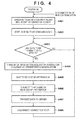
- FIG. 6 shows the flow of the processes performed in the smartphone 101, particularly by the AP information notification unit 504.
- the AP information notification unit 504 starts its operation when triggered by the turning on of the smartphone 101, or the activation of predetermined application software in the smartphone 101.
- the AP information notification unit 504 first waits to receive an advertising packet from the camera 100 by using the BLE communication unit 502 (step S601). Then, upon receiving the advertising packet, the AP information notification unit 504 transmits a connection request to the camera 100, and starts periodic transmission/reception of packets via intermittent communication by BLE (step S602). Next, the AP information notification unit 504 waits to receive a request for the AP information from the camera 100 via intermittent communication by BLE (step S603).
- the AP information notification unit 504 Upon receiving the request for the AP information, the AP information notification unit 504 inquires the AP information obtaining unit 503 as to whether or not the AP 102 is present in the proximity (e.g. the communicable range of the smartphone 101), and as to whether or not its connection parameters have been obtained (step S604). Note that the AP information obtaining unit 503 performs a search after receiving the request for the AP information from the camera 100, for example, in order to determine whether or not the AP is present in the proximity of the smartphone 101. Also, the AP information obtaining unit 503 may determine whether or not an AP is present in the proximity of the smartphone 101 according to whether or not there is an AP to which the smartphone 101 connects.
- the AP information obtaining unit 503 also performs the process of obtaining the connection parameters for connecting to the AP found in the search.
- the AP information obtaining unit 503 it is unnecessary for the AP information obtaining unit 503 to newly obtain connection parameters because the purpose can be satisfied by notification of the connection parameters that are being used for the connection.
- the AP information notification unit 504 controls the BLE communication unit 502 so that it transmits the AP information over the subsequent sequence of intermittent communication (step S605). After that, the AP information notification unit 504 goes back to step S603, and waits to receive a request for the AP information again.
- the AP information includes, for example, information indicating that the AP 102 is present in the proximity at the timing when the AP information is transmitted, and the connection parameters used for connecting to the AP 102.
- the AP information notification unit 504 waits until the AP 102 is present in the proximity and its connection parameters are obtained. Note that even while performing any of the steps above, the AP information notification unit 504 goes back to step S601 whenever BLE communication with the camera 100 is disconnected. In other words, while BLE communication is maintained after the request for the AP information has been received, it is possible to confirm that the camera 100 wishes to connect to the network, unless the request is cancelled for a particular reason. However, if BLE communication is disconnected, it will be impossible to confirm that, and accordingly the processing will be reset in such a case.
- a data packet 700 is a BLE data packet including AP information.
- the data packet 700 includes a preamble 701, an access address 702, a PDU (Protocol Data Unit) 703, and a CRC (Cyclic Redundancy Check) 704.
- the preamble 701 is used for determining the beginning of the packet.
- the access address 702 represents that communication is performed between the camera 100 and the smartphone 101.
- the CRC 704 is used for error detection, and is calculated based on the content of the PDU 703.
- the PDU 703 is configured to include a header 711 and a payload 712, and the header 711 includes information indicating that this packet is a data packet, and information indicating the length of the payload 712. When there is no data to be transmitted via intermittent communication, this length is 0. However, in a data packet including the AP information, the value of the length is equal to or greater than 1.
- the payload 712 includes a data type 721, an AP identifier 722, a security system type 723, and a password 724.
- the data type 721 stores a value indicating that this data packet includes AP information.
- the information indicated by the connection parameters for the AP identified by the AP identifier 722 is stored in the AP identifier 722, the security system type 723, and the password 724.
- the camera 100 Upon receiving this data packet, the camera 100 can find out that the data packet includes AP information by reading the value of the data type 721, and accordingly can find out the timing at which the AP information has been transmitted.
- the data type 721 is information indicating whether or not the AP specified by the AP identifier 722 is present in the proximity (communicable range) of the smartphone 101 at the timing of the transmission of the data packet.
- the header 711 may also include information indicating whether or not it is followed by a data packet.
- the connection parameters may be divided into a plurality of data packets by using the information before being transmitted.
- the AP information requesting unit 303 may transmit the request for the AP information in the form of a data packet from the camera 100 to the smartphone 101 as with the above case, by setting the value of the data type 721 in the PDU to be a value indicating that this data packet is a request for the AP information.
- the data packet format above is merely an example, and the AP information may be transmitted in other formats.
- step S601 the smartphone 101 enters into the state of waiting to receive an advertising packet.
- step S602 an advertising packet is transmitted from the camera 100 at time 803 (step S402).
- step S402 the smartphone 101 transmits a connection request at time 804 (step S602). Consequently, intermittent communication between the camera 100 and the smartphone 101 via BLE starts (step S403, step S602), and the smartphone 101 enters into the state of waiting for a request for the AP information from the camera 100 (step S603).
- the camera 100 transmits a request for the AP information to the smartphone 101 by the sequence of the intermittent communication at time 806, and comes into the state of waiting to receive the AP information (steps S403 to S405).
- the smartphone 101 comes into the state of waiting for the presence of an AP within the communicable range of the smartphone 101 itself, and waiting for obtaining the AP information of the AP (step S604).
- the smartphone 101 When the user goes back home at time 807, the smartphone 101 connects to the AP at the user's home as operated by the user or automatically, and consequently the smartphone 101 enters into the situation where an AP is present in its proximity and the connection parameters for the AP have been obtained. Accordingly, the smartphone 101 transmits the AP information to the camera 100 at time 808 when the subsequent sequence of the intermittent communication occurs (step S605). At the time of receiving the AP information, the camera 100 can recognize the presence of a connectable AP in its proximity, and simultaneously, it can obtain the connection parameters for the AP.
- the camera 100 connects to the AP that corresponds to the AP information notified by the smartphone 101, and transmits the captured image to the server on the network via the AP (step S406, step S407). After that, upon completing the data transmission, the camera 100 disconnects the connection with the AP (step S408).
- the camera 100 can automatically connect to the AP at the user's home and transmit the image to the server.
- the connecting of the smartphone 101 to the AP at the user's home at the time 807 is, in many cases, performed manually or automatically regardless of the presence of the camera 100.
- wireless LAN communication when compared to cellular communication, is faster and cheaper, and allows users to use services such as calling and data communication almost in the same manner as with cellular communication, and, in many cases, wireless LAN communication is preferentially used by smartphones in locations where an AP is present.
- the wireless communication system it is possible to connect the camera to the network without performing an operation that is solely for connecting the camera to the wireless LAN, and thus user convenience is improved. Also, the camera according to the present embodiment can be realized by simply adding only the BLE communication function to an ordinary camera, which does not cause a significant increase in size or cost compared to adding the NFC communication function.
- Embodiment 1 an example is described in which the camera 100 transmits a request for AP information used for connecting to an AP that can connect to the network without specifying the AP.
- the camera 100 specifies a particular AP, and makes a request for the AP information of the particular AP.
- FIG. 9 shows an example of the functional configuration of the camera 100 according to the present embodiment.
- the camera 100 according to the present embodiment has a similar configuration to the configuration represented by the block diagram shown in FIG. 3 described for Embodiment 1, except that an AP identifier setting unit 901 is added. Therefore, the following describes the differences from Embodiment 1, and the description of the parts having similar functions as in Embodiment 1 has been omitted.
- the AP identifier setting unit 901 has an interface for, when the AP information requesting unit 303 detects in step S406 shown in FIG. 4 that AP information is obtained, displaying a screen as shown in FIG. 10 and accepting an operation, based on the AP identifier contained in the AP information.
- the AP identifier setting unit 901 has the function of showing connectable APs to the user, and obtaining the designation of an AP to connect to from the user.
- the AP identifier setting unit 901 stores the connection parameters contained in the AP information when the user selects "YES" in FIG. 10 .
- the AP identifier setting unit 901 controls the AP information requesting unit 303 so that, when transmitting an AP information request later in step S404, the AP information requesting unit 303 transmits the AP information request together with the AP identifier, which is contained in the connection parameters, by including it in the AP information request.
- FIG. 11 is a flowchart showing the flow of processes performed by the AP information notification unit 504 of the smartphone 101 according to the present embodiment. Note that in FIG. 11 the steps of performing the same process as in FIG. 6 are given the same reference numbers, and the description of them has been omitted unless necessary.
- the AP information notification unit 504 After waiting to receive an AP information request via intermittent communication (step S603), the AP information notification unit 504 determines whether or not the received AP information request contains an AP identifier (step S1101). Then, when the AP information request does not contain an AP identifier (NO in step S1101), the AP information notification unit 504 proceeds to step S604, and performs the same processes as in Embodiment 1. On the other hand, when an AP identifier is contained (YES in step S1101), the AP information notification unit 504 waits until the AP information obtaining unit 503 detects that the AP having the AP identifier is present in its proximity (step S1102).
- the AP information notification unit 504 proceeds to step S605, and transmits its AP information to the camera 100.
- the camera 100 is holding the connection parameters for the AP because the AP information to be transmitted is that of the AP that has been specified from the camera 100.
- the AP information notification unit 504 notifies only of the AP information of the AP that has the AP identifier specified from the camera 100.
- the user can enable the camera 100 to connect only to the AP at home from then on. Consequently, the user can perform uploading from the camera 100 to the server via the AP at home, which has a relatively stable connection status, and it is therefore possible to reduce the possibility that uploading results in failure due to connection to an AP having an unstable connection status while the user is moving outside the home.
- a request for AP information can be transmitted in the form of a data packet, in which the data type 721 having a predetermined value is included in the PDU.
- a request for AP information can be included in the PDU of an advertising packet, in a similar format. Therefore, a request for AP information may be transmitted in the form of an advertising packet instead of a data packet.
- transmission of an advertising packet in which the PDU does not contain the data type 721 may be regarded as transmission of a request for AP information. In both cases, in response to receiving the advertising packet, the smartphone 101 can determine that it has received a request for AP information.
- the AP information notification unit 504 waits until the AP information obtaining unit 503 obtains the AP information in step S604 in FIG. 6 either according to a user operation or automatically. Instead of performing this process, the AP information notification unit 504 may request the AP information obtaining unit 503 to perform a passive scan when receiving a request for AP information via intermittent communication in step S603. Consequently, when a connectable AP is present in the proximity when the user captures an image, the user can connect the camera to the AP immediately after capturing the image, and upload the captured image to the server.
- the AP information requesting unit 303 may transition to the sleep state after transmitting a request for AP information in step S404 in FIG. 4 .
- the camera 100 may cause, not only the AP information requesting unit 303, but also some of the functions of the camera 100, except for the functions of the BLE communication unit 302, to transition to the sleep state.
- some independent communication modules output an interruption signal when receiving a data packet that is not empty. By using this interruption signal as a wakeup signal, it is possible to reduce the power consumption of the camera 100 during the period from the time 806 in FIG. 8 , at which a request for AP information is transmitted, to the time 808, at which the AP information is received. Consequently, the frequency with which the user charges the battery of the camera can be reduced, and the convenience can be improved.
- the present invention in a communication system including a plurality of apparatuses among which information used for connecting to another apparatus is exchanged, user convenience when the information used for the connection is exchanged can be improved.
- Embodiment(s) of the present invention can also be realized by a computer of a system or apparatus that reads out and executes computer executable instructions (e.g., one or more programs) recorded on a storage medium (which may also be referred to more fully as a 'non-transitory computer-readable storage medium') to perform the functions of one or more of the above-described embodiment(s) and/or that includes one or more circuits (e.g., application specific integrated circuit (ASIC)) for performing the functions of one or more of the above-described embodiment(s), and by a method performed by the computer of the system or apparatus by, for example, reading out and executing the computer executable instructions from the storage medium to perform the functions of one or more of the above-described embodiment(s) and/or controlling the one or more circuits to perform the functions of one or more of the above-described embodiment(s).
- computer executable instructions e.g., one or more programs
- a storage medium which may also be referred to more fully as
- the computer may comprise one or more processors (e.g., central processing unit (CPU), micro processing unit (MPU)) and may include a network of separate computers or separate processors to read out and execute the computer executable instructions.
- the computer executable instructions may be provided to the computer, for example, from a network or the storage medium.
- the storage medium may include, for example, one or more of a hard disk, a random-access memory (RAM), a read only memory (ROM), a storage of distributed computing systems, an optical disk (such as a compact disc (CD), digital versatile disc (DVD), or Blu-ray Disc (BD)TM), a flash memory device, a memory card, and the like.
Abstract
Description
- The present invention relates to communication setting technology for wireless communication.
- In recent years, an increasing number of products such as digital cameras are equipped with a communication function that uses a wireless local area network (LAN). Consequently, using the communication function, a digital camera, for example, is capable of uploading a captured image to a server on the Internet so that a plurality of users can share the captured image. To transmit data to the Internet by using a wireless LAN, the user of the camera needs to perform an operation to connect the camera to one of the access points (APs) of the wireless LAN that are located in the proximity of the camera. In other words, the user of the camera needs to input the identifier of an AP, or connection parameters including security system information, a password, etc., to the camera, and cause the camera to start connecting to the AP, in a location where the camera can communicate with the AP.
- Meanwhile, an increasing number of mobile communication devices such as smartphones are now equipped with a communication function that uses a cellular system and a wireless LAN, and also near field communication (NFC), Bluetooth ® low energy (BLE), etc. Note that NFC is a communication standard that is suitable for, upon a touch operation as a trigger, transmitting and receiving data within a short period for which the device is being touched. Also note that BLE is a communication standard that is suitable for maintaining intermittent communication in which, for example, one communication sequence occurs every second or so, over a long period, with low power consumption.
- Smartphones have a user interface that is suitable for inputting characters, and in general, inputting connection parameters from these devices is easier than performing similar inputting from cameras in many cases. Furthermore, many smartphones have the function of automatically finding and connecting to a connectable AP by using, for example, connection parameters obtained by reading a QR code (TM), or connection parameters input in the past. However, it is not easy to equip cameras with a function that is similar to the function of smartphones for reasons such as the cost, size, etc.
- In this regard, using a camera having the function of receiving the connection parameters of a wireless LAN from a smartphone by NFC, the user can input the connection parameters to the camera and connect the camera to the wireless LAN by simply touching the camera to the smartphone. As such technology, Japanese Patent Laid-open No.
2010-245748 - However, when using the technology disclosed in Japanese Patent Laid-open No.
2010-245748 - The present invention is made in view of the above problem, and in a communication system including a plurality of apparatuses among which information used for connecting to another apparatus is exchanged, the present invention provides a technology for improving user convenience when the information used for the connection is exchanged.
- The present invention in its first aspect provides a communication system as specified in claim 1.
- The present invention in its second aspect provides a communication apparatus as specified in claims 2 to 10.
- The present invention in its third aspect provides a communication method as specified in claim 11.
- The present invention in its fourth aspect provides a communication apparatus control method as specified in claim 12.
- The present invention in its fifth aspect provides a program as specified in claim 13.
- The present invention in its sixth aspect provides a storage medium as specified in claim 14.
- Further features of the present invention will become apparent from the following description of embodiments (with reference to the attached drawings).
- The accompanying drawings, which are incorporated in and constitute a part of the specification, illustrate embodiments of the invention, and together with the description, serve to explain the principles of the invention.
-
FIG. 1 is a diagram showing an example of a configuration of a wireless communication system. -
FIG. 2 is a sequence diagram showing a flow of BLE communication. -
FIG. 3 is a block diagram showing an example of a functional configuration of acamera 100. -
FIG. 4 is a flowchart showing a flow of processes performed by an APinformation requesting unit 303 of thecamera 100. -
FIG. 5 is a block diagram showing an example of a functional configuration of asmartphone 101. -
FIG. 6 is a flowchart showing a flow of processes performed by an APinformation notification unit 504 of thesmartphone 101. -
FIG. 7 is a diagram showing an example of a format for AP information transmitted from thesmartphone 101. -
FIG. 8 is a sequence diagram showing an example of a flow of processes performed by thecamera 100 and thesmartphone 101. -
FIG. 9 is a block diagram showing another example of the functional configuration of thecamera 100. -
FIG. 10 is a diagram showing an example of a screen displayed by an APidentifier setting unit 901. -
FIG. 11 is a flowchart showing a flow of other processes performed by the APinformation notification unit 504 of thesmartphone 101. - Embodiments of the present invention will now be described in detail with reference to the drawings. It should be noted that the relative arrangement of the components, the numerical expressions and numerical values set forth in these embodiments do not limit the scope of the present invention unless it is specifically stated otherwise. Each of the embodiments of the present invention described below can be implemented solely or as a combination of a plurality of the embodiments or features thereof where necessary or where the combination of elements or features from individual embodiments in a single embodiment is beneficial.
-
FIG. 1 shows an example of the configuration of a wireless communication system according to the present embodiment. In this wireless communication system, acamera 100, for example, uploads captured image data to aserver 103 on a network (e.g. the Internet) via an access point (AP) 102 of a wireless LAN. Thecamera 100 obtains AP information, which is for connecting to the AP 102, from asmartphone 101 by wireless communication that is based on the Bluetooth low energy (BLE) communication standard. The AP information includes, for example, information indicating that the AP 102 is present in the proximity of thesmartphone 101 at the timing when the AP information is transmitted, and connection parameters used for connecting to the AP 102. The connection parameters include, for example, the AP identifier of theAP 102, information indicating the security system type of theAP 102, and password information required to connect to the AP 102 by using the security system. An AP identifier is, for example, the identifier that identifies an AP, or the identifier of a wireless LAN network formed by an AP, and a service set identifier (SSID) or the like may be used as an AP identifier. Serving as a terminal in the wireless LAN, thecamera 100 connects to the AP 102 based on the AP information. - Note that, in the following description, it is the
camera 100 and thesmartphone 101 that perform communication for establishing a wireless LAN connection between thecamera 100 and the AP 102, but these are merely examples, and other devices having the communication function may be used. In other words, the following accounts apply to, in general terms, any system in which a first communication apparatus and a second communication apparatus perform communication for establishing a connection between the first communication apparatus and a third communication apparatus. Also note that the "third communication apparatus" mentioned above is not necessarily a particular communication apparatus, and may be any communication apparatus that can connect to theserver 103 on the network. In other words, the third communication apparatus may be, for example, an access point of a wireless LAN that is connected to a wired network and establishes a wireless network, or a communication apparatus that is capable of connecting to a network for wirelessly connecting to theserver 103. - Furthermore, although the following provides a description of a case in which the
camera 100 and thesmartphone 101 perform communication by BLE and communication between thecamera 100 or thesmartphone 101 and the AP 102 is performed via a wireless LAN, this is not a limiting description by any means. In other words, thecamera 100 or thesmartphone 101 and the AP 102 may perform communication with each other via a wireless network that uses a method other than the wireless LAN method, and thecamera 100 and thesmartphone 101 may perform communication with each other by using a method other than the BLE method. Also, in the case where a wireless LAN is used, the wireless LAN to be used may be a wireless LAN complying with the series of IEEE 802.11 standards for example, or any of the past, present, or future wireless LANs. Similarly, other communication methods to be used may be any of the past, present, or future methods. - Next, a description is given of the flow of BLE communication performed between the
camera 100 and thesmartphone 101 in the wireless communication system according to the present embodiment.FIG. 2 is a sequence diagram showing an example of the flow of BLE communication performed by thecamera 100 and thesmartphone 101. - In this example, first, the
camera 100 repeatedly and periodically transmits an advertising packet at predetermined intervals. The advertising packet mentioned here is, for example, a packet used for finding the other party performing BLE communication, in order to obtain the AP information that is necessary for thecamera 100 to connect to another communication apparatus (e.g. the AP 102) that is used for connecting to a network. Upon receiving the advertising packet from thecamera 100, thesmartphone 101 transmits a connection request to thecamera 100. - Consequently, a BLE communication connection is established between the
camera 100 and thesmartphone 101, and thereafter a transition to intermittent communication occurs, by which data packets are periodically exchanged at predetermined intervals. Note that in order to perform intermittent communication in synchronization with each other, thecamera 100 needs to obtain from thesmartphone 101 information about the timing of starting intermittent communication, and information about the intervals of the intermittent communication, and these pieces of information are contained in the connection request packet. Also note that when there is no data to be transmitted to the other party, thecamera 100 and thesmartphone 101 exchange data packets at the intervals of the intermittent communication. The communication apparatus on the transmission side transmits information indicating whether or not data to be transmitted is contained in the data packet by including the information in the data packet, and the communication apparatus on the reception side can determine whether or not the packet includes significant data by checking the information. - When it is necessary to connect to the AP 102 (connect to the network), the
camera 100 requests thesmartphone 101 for the AP information by using the data packet for the subsequent sequence of intermittent communication. Note that the AP information requested here is not necessarily the information of theparticular AP 102, and may be information of any AP that can connect to the network. Therefore, this request for the AP information can be regarded as a signal indicating that thecamera 100 wishes to connect to the network. In other words, the data packet in this case can be regarded as a signal for notifying thesmartphone 101 that thecamera 100 wishes to connect to the network. - After receiving this request, upon detecting that an AP (e.g. the AP 102) that can connect to the network is present in the proximity, the
smartphone 101 transmits the AP information of the AP by using the data packet for the sequence of intermittent communication that is subsequent to the timing of detection. Note that "proximity" mentioned here is the communicable range for thesmartphone 101 via the wireless LAN. As described above, this AP information includes, for example, information indicating that theAP 102 is present in the proximity of thesmartphone 101 at the timing when the AP information is transmitted, and connection parameters used for connecting to theAP 102. - Note that since the communicable range of BLE communication has a sufficiently short distance, if the
AP 102 is present in the proximity of thesmartphone 101, it can be estimated that thecamera 100, which is the communication partner to thesmartphone 101 by BLE communication, is also present in the proximity of theAP 102. Therefore, by being notified that thesmartphone 101 has detected theAP 102 in its proximity, and being provided with the AP information of theAP 102, thecamera 100 can connect to theAP 102, and can connect to, for example, theserver 103 via theAP 102. - Here, if the intervals of intermittent communication are long, there is the possibility that during the period from when the
smartphone 101 detects the presence of theAP 102 in its proximity to when the subsequent sequence of the intermittent communication occurs, the user holding thesmartphone 101 moves to a location where thesmartphone 101 cannot perform wireless LAN communication with theAP 102. Therefore, the intervals of the intermittent communication may be set with consideration of the movement of thesmartphone 101, and may be set to approximately 1 second, for example. - Note that the
smartphone 101 has ordinary functions required to obtain the AP identifiers of APs in its proximity. In other words, thesmartphone 101 has, for example, the function of obtaining the AP identifiers by performing a passive scan prescribed by the wireless LAN standard, and receiving a beacon that is periodically transmitted from each AP in its proximity. Furthermore, thesmartphone 101 has a user interface, from which the user makes an instruction to perform a passive scan. Note that thesmartphone 101 may have the function of automatically performing a scan, instead of the user interface, or in addition to the user interface. Furthermore, thesmartphone 101 may have the function of automatically performing a scan when it is in a location where an AP is likely to be present, by using positional information. - Furthermore, the
smartphone 101 has ordinary functions required to obtain the connection parameters other than the AP identifier as well, with respect to one AP out of the APs in its proximity. In other words, thesmartphone 101 has, for example, the function of displaying a list of the AP identifiers found by a passive scan, and an acceptance function, which is the function of allowing the user to select one of the AP identifiers and accepting user input of the security system and password corresponding to the selected AP. Note that the acceptance function may be, for example, a software or hardware keyboard function, or the function of capturing and analyzing a QR code or the like. Also, thesmartphone 101 may have the function of storing input content accepted in the past so that thereafter input of the same content by the user can be avoided. - Next, a description is given of an example of the configuration of the
camera 100 and the flow of processes performed by thecamera 100.FIG. 3 is a block diagram showing an example of the functional configuration of thecamera 100. Thecamera 100 includes, for example, a wirelessLAN communication unit 301, aBLE communication unit 302, an APinformation requesting unit 303, animage storing unit 304, and animage capturing unit 305. Note that functions not related to the present embodiment, such as a calling function, are not depicted in the drawing, and their description has been omitted. - The wireless
LAN communication unit 301 includes, for example, an ordinary antenna, a modulation and demodulation function, and a protocol processing function, which are required for wireless LAN communication, and the wirelessLAN communication unit 301 connects to theAP 102, reads out image data stored in theimage storing unit 304 for example, and transmits it to theAP 102. Note that the image data transmitted to theAP 102 is transferred to theserver 103, via a network for example. TheBLE communication unit 302 includes, for example, an ordinary antenna, a modulation and demodulation function, and a protocol processing function, which are required for BLE communication, and, as described above, theBLE communication unit 302 establishes a connection with thesmartphone 101 by BLE communication and performs intermittent communication with thesmartphone 101. - The AP
information requesting unit 303 obtains the AP information from thesmartphone 101 by using theBLE communication unit 302, and, based on the AP information, outputs the timing at which the wirelessLAN communication unit 301 connects to theAP 102, and the connection parameters for theAP 102, to the wirelessLAN communication unit 301. The wirelessLAN communication unit 301 connects to theAP 102 according to these pieces of information. - The
image storing unit 304 stores, for example, image data captured by theimage capturing unit 305. Theimage capturing unit 305 performs image capturing according to a user operation, generates image data, and stores it to theimage storing unit 304. Note that theimage storing unit 304 can store the image data of not only one image, but of a plurality of images. - Note that the
camera 100 may have, for example, hardware modules constituting at least one CPU, at least one ROM, at least one RAM, and so on, which are not shown inFIG. 3 , and the CPU may perform the processes represented by the flowchart described below by executing a program stored in the ROM. -
FIG. 4 shows the flow of the processes performed in thecamera 100, particularly by the APinformation requesting unit 303. The APinformation requesting unit 303 starts its operation when triggered by the turning on of the power of the camera. The APinformation requesting unit 303 repeatedly transmits the advertising packet at predetermined intervals by using the BLE communication unit 302 (step S401), and starts periodically transmitting/receiving signals via intermittent communication in response to receiving a connection request from the smartphone 101 (step S402). - After that, the AP
information requesting unit 303 determines whether or not there is any data to be transmitted to the server 103 (step S403). Here, the data to be transmitted to the server may be, for example, image data in theimage storing unit 304, which has not been transmitted yet, or image data specified by the user. Upon the occurrence of data to be transmitted (YES in step S403), the APinformation requesting unit 303 controls theBLE communication unit 302 to transmit the AP information request by using the data packet for the subsequent sequence of the intermittent communication (step S404). Then, the APinformation requesting unit 303 waits to receive the AP information from thesmartphone 101 via a subsequent sequence of the intermittent communication (step S405). - Then, upon receiving the AP information, the AP
information requesting unit 303 controls the wirelessLAN communication unit 301 so that it connects to theAP 102 by using the connection parameters contained in the AP information thus received, thereby connecting thecamera 100 to the AP 102 (step S406). Next, the APinformation requesting unit 303 controls the wirelessLAN communication unit 301 so that it transmits the data to be transmitted, which has been determined in step S403, to theserver 103 via the AP 102 (step S407). Then, upon completing the transmission of the data to be transmitted, the APinformation requesting unit 303 controls the wirelessLAN communication unit 301 so that it disconnects the connection with the AP 102 (step S408), and awaits the next occurrence of data to be transmitted (step S403). - Note that it is not necessary for the AP
information requesting unit 303 to perform a control to disconnect the connection with the AP (step S408) immediately after transmitting the data to be transmitted to the server 103 (step S407). In other words, the APinformation requesting unit 303 may wait for a predetermined period of time after the data to be transmitted has been transmitted to the server 103 (step S407), thereby confirming that there will be no data to be additionally transmitted to the server, and then disconnect the connection with the AP (step S408). If it is determined within this predetermined period that there is further data to be transmitted to theserver 103, the APinformation requesting unit 303 transmits this further data as well (step S407). Consequently, it is possible to avoid unnecessarily disconnecting and/or re-establishing the connection via the wireless LAN. Note that even while performing any of the steps above, the APinformation requesting unit 303 goes back to step S401 whenever BLE communication with thesmartphone 101 is disconnected. In other words, while BLE communication is maintained after the request for the AP information has been transmitted, it is possible to confirm that thecamera 100 wishes to connect to the network, unless the request is cancelled for a particular reason. However, if BLE communication is disconnected, it will be impossible to confirm that, and accordingly the processing will be reset in such a case. - Note that if the
camera 100 is not notified of the AP information despite maintaining the connection over the predetermined period by BLE communication, thecamera 100 may determine not to make an attempt to connect to the network for a while, and disconnect BLE communication. Then, after another predetermined period has elapsed, thecamera 100 may establish BLE communication again, and make a request for the AP information. Consequently, it is possible to prevent thecamera 100 from continuously performing periodic transmission/reception of signals via BLE in a situation where the connection with the AP cannot be established, which leads to a reduction in power consumption by thecamera 100. - Next, a description is given of an example of the functional configuration of the
smartphone 101 and the flow of processes performed by thesmartphone 101.FIG. 5 is a block diagram showing an example of the functional configuration of thesmartphone 101. Thesmartphone 101 includes, for example, a wirelessLAN communication unit 501, aBLE communication unit 502, an APinformation obtaining unit 503, and an APinformation notification unit 504. Note that functions not directly related to the present embodiment, such as a calling function, are not depicted in the drawing, and their description has been omitted from that ofFIG. 5 . - The wireless
LAN communication unit 501 and theBLE communication unit 502 are respectively similar to the wirelessLAN communication unit 301 and theBLE communication unit 302, and each has an ordinary antenna, a modulation and demodulation function, and a protocol processing function, which are required for wireless LAN communication and BLE communication. The APinformation obtaining unit 503 has ordinary functions required to obtain the AP identifiers of APs in the proximity of thesmartphone 101, and the connection parameters of one of the APs in its proximity, as described above. By using these functions, after receiving the request for the AP information from thecamera 100, the APinformation obtaining unit 503 detects theAP 102 in its proximity and obtains the connection parameters used for connecting to theAP 102. The APinformation notification unit 504 notifies thecamera 100 of the AP information obtained by the APinformation obtaining unit 503 based on the AP information request received from thecamera 100 via theBLE communication unit 502. The AP information serves as a response to the request. Note that thesmartphone 101 may have, for example, hardware modules constituting at least one CPU, at least one ROM, at least one RAM, and so on, which are not shown inFIG. 5 , and the CPU may perform the processes represented by the flowchart described below by executing a program stored in the ROM. -
FIG. 6 shows the flow of the processes performed in thesmartphone 101, particularly by the APinformation notification unit 504. The APinformation notification unit 504 starts its operation when triggered by the turning on of thesmartphone 101, or the activation of predetermined application software in thesmartphone 101. The APinformation notification unit 504 first waits to receive an advertising packet from thecamera 100 by using the BLE communication unit 502 (step S601). Then, upon receiving the advertising packet, the APinformation notification unit 504 transmits a connection request to thecamera 100, and starts periodic transmission/reception of packets via intermittent communication by BLE (step S602). Next, the APinformation notification unit 504 waits to receive a request for the AP information from thecamera 100 via intermittent communication by BLE (step S603). - Upon receiving the request for the AP information, the AP
information notification unit 504 inquires the APinformation obtaining unit 503 as to whether or not theAP 102 is present in the proximity (e.g. the communicable range of the smartphone 101), and as to whether or not its connection parameters have been obtained (step S604). Note that the APinformation obtaining unit 503 performs a search after receiving the request for the AP information from thecamera 100, for example, in order to determine whether or not the AP is present in the proximity of thesmartphone 101. Also, the APinformation obtaining unit 503 may determine whether or not an AP is present in the proximity of thesmartphone 101 according to whether or not there is an AP to which thesmartphone 101 connects. Note that in the case of performing a search for an AP, the APinformation obtaining unit 503 also performs the process of obtaining the connection parameters for connecting to the AP found in the search. On the other hand, when there is an AP that is connected, it is unnecessary for the APinformation obtaining unit 503 to newly obtain connection parameters because the purpose can be satisfied by notification of the connection parameters that are being used for the connection. - When the
AP 102 is present in the proximity and its connection parameters have been obtained (YES in step S604), the APinformation notification unit 504 controls theBLE communication unit 502 so that it transmits the AP information over the subsequent sequence of intermittent communication (step S605). After that, the APinformation notification unit 504 goes back to step S603, and waits to receive a request for the AP information again. The AP information includes, for example, information indicating that theAP 102 is present in the proximity at the timing when the AP information is transmitted, and the connection parameters used for connecting to theAP 102. - On the other hand, when the
AP 102 is not present in the proximity, or its connection parameters have not been obtained (NO in step S604), the APinformation notification unit 504 waits until theAP 102 is present in the proximity and its connection parameters are obtained. Note that even while performing any of the steps above, the APinformation notification unit 504 goes back to step S601 whenever BLE communication with thecamera 100 is disconnected. In other words, while BLE communication is maintained after the request for the AP information has been received, it is possible to confirm that thecamera 100 wishes to connect to the network, unless the request is cancelled for a particular reason. However, if BLE communication is disconnected, it will be impossible to confirm that, and accordingly the processing will be reset in such a case. - Here, a description is given of the format for the AP information transmitted from the
smartphone 101, with reference toFIG. 7 . InFIG. 7 , adata packet 700 is a BLE data packet including AP information. Thedata packet 700 includes apreamble 701, anaccess address 702, a PDU (Protocol Data Unit) 703, and a CRC (Cyclic Redundancy Check) 704. Thepreamble 701 is used for determining the beginning of the packet. Theaccess address 702 represents that communication is performed between thecamera 100 and thesmartphone 101. TheCRC 704 is used for error detection, and is calculated based on the content of thePDU 703. - Here, the
PDU 703 is configured to include aheader 711 and apayload 712, and theheader 711 includes information indicating that this packet is a data packet, and information indicating the length of thepayload 712. When there is no data to be transmitted via intermittent communication, this length is 0. However, in a data packet including the AP information, the value of the length is equal to or greater than 1. Thepayload 712 includes adata type 721, anAP identifier 722, asecurity system type 723, and apassword 724. Thedata type 721 stores a value indicating that this data packet includes AP information. The information indicated by the connection parameters for the AP identified by theAP identifier 722 is stored in theAP identifier 722, thesecurity system type 723, and thepassword 724. - Upon receiving this data packet, the
camera 100 can find out that the data packet includes AP information by reading the value of thedata type 721, and accordingly can find out the timing at which the AP information has been transmitted. In other words, thedata type 721 is information indicating whether or not the AP specified by theAP identifier 722 is present in the proximity (communicable range) of thesmartphone 101 at the timing of the transmission of the data packet. - Note that according to the BLE communication standard, the
header 711 may also include information indicating whether or not it is followed by a data packet. When the size of the connection parameters is large, the connection parameters may be divided into a plurality of data packets by using the information before being transmitted. Also, the APinformation requesting unit 303 may transmit the request for the AP information in the form of a data packet from thecamera 100 to thesmartphone 101 as with the above case, by setting the value of thedata type 721 in the PDU to be a value indicating that this data packet is a request for the AP information. - Note that the data packet format above is merely an example, and the AP information may be transmitted in other formats.
- Next, a description is given of the flow of the processes performed between the
camera 100 and thesmartphone 101, with reference toFIG. 8 . Note that the following describes, for example, a case where the user goes out carrying thecamera 100 and thesmartphone 101, captures an image with thecamera 100, and goes back home, and then thesmartphone 101 connects to the AP at the home. - First, in response to the user turning on the power of the
smartphone 101 attime 801, thesmartphone 101 enters into the state of waiting to receive an advertising packet (step S601). Next, in response to the user turning on the power of thecamera 100 attime 802, an advertising packet is transmitted from thecamera 100 at time 803 (step S402). In response to this advertising packet, thesmartphone 101 transmits a connection request at time 804 (step S602). Consequently, intermittent communication between thecamera 100 and thesmartphone 101 via BLE starts (step S403, step S602), and thesmartphone 101 enters into the state of waiting for a request for the AP information from the camera 100 (step S603). - After that, when the user performs an image capturing operation with the
camera 100 attime 805, image data to be transmitted occurs in thecamera 100. Accordingly, thecamera 100 transmits a request for the AP information to thesmartphone 101 by the sequence of the intermittent communication attime 806, and comes into the state of waiting to receive the AP information (steps S403 to S405). Upon receiving the request for the AP information, thesmartphone 101 comes into the state of waiting for the presence of an AP within the communicable range of thesmartphone 101 itself, and waiting for obtaining the AP information of the AP (step S604). - When the user goes back home at
time 807, thesmartphone 101 connects to the AP at the user's home as operated by the user or automatically, and consequently thesmartphone 101 enters into the situation where an AP is present in its proximity and the connection parameters for the AP have been obtained. Accordingly, thesmartphone 101 transmits the AP information to thecamera 100 attime 808 when the subsequent sequence of the intermittent communication occurs (step S605). At the time of receiving the AP information, thecamera 100 can recognize the presence of a connectable AP in its proximity, and simultaneously, it can obtain the connection parameters for the AP. Accordingly, attime 809, thecamera 100 connects to the AP that corresponds to the AP information notified by thesmartphone 101, and transmits the captured image to the server on the network via the AP (step S406, step S407). After that, upon completing the data transmission, thecamera 100 disconnects the connection with the AP (step S408). - As described above, although only the power-on operation at the
time 802 and the image capturing operation at thetime 805 are the operations performed by the user on thecamera 100, thecamera 100 can automatically connect to the AP at the user's home and transmit the image to the server. Note that the connecting of thesmartphone 101 to the AP at the user's home at thetime 807 is, in many cases, performed manually or automatically regardless of the presence of thecamera 100. This is because wireless LAN communication, when compared to cellular communication, is faster and cheaper, and allows users to use services such as calling and data communication almost in the same manner as with cellular communication, and, in many cases, wireless LAN communication is preferentially used by smartphones in locations where an AP is present. Therefore, according to the wireless communication system according to the present embodiment, it is possible to connect the camera to the network without performing an operation that is solely for connecting the camera to the wireless LAN, and thus user convenience is improved. Also, the camera according to the present embodiment can be realized by simply adding only the BLE communication function to an ordinary camera, which does not cause a significant increase in size or cost compared to adding the NFC communication function. - In Embodiment 1, an example is described in which the
camera 100 transmits a request for AP information used for connecting to an AP that can connect to the network without specifying the AP. In contrast, in the present embodiment a case is described where thecamera 100 specifies a particular AP, and makes a request for the AP information of the particular AP. -
FIG. 9 shows an example of the functional configuration of thecamera 100 according to the present embodiment. Thecamera 100 according to the present embodiment has a similar configuration to the configuration represented by the block diagram shown inFIG. 3 described for Embodiment 1, except that an APidentifier setting unit 901 is added. Therefore, the following describes the differences from Embodiment 1, and the description of the parts having similar functions as in Embodiment 1 has been omitted. - The AP
identifier setting unit 901 has an interface for, when the APinformation requesting unit 303 detects in step S406 shown inFIG. 4 that AP information is obtained, displaying a screen as shown inFIG. 10 and accepting an operation, based on the AP identifier contained in the AP information. In other words, the APidentifier setting unit 901 has the function of showing connectable APs to the user, and obtaining the designation of an AP to connect to from the user. Furthermore, the APidentifier setting unit 901 stores the connection parameters contained in the AP information when the user selects "YES" inFIG. 10 . Then, the APidentifier setting unit 901 controls the APinformation requesting unit 303 so that, when transmitting an AP information request later in step S404, the APinformation requesting unit 303 transmits the AP information request together with the AP identifier, which is contained in the connection parameters, by including it in the AP information request. -
FIG. 11 is a flowchart showing the flow of processes performed by the APinformation notification unit 504 of thesmartphone 101 according to the present embodiment. Note that inFIG. 11 the steps of performing the same process as inFIG. 6 are given the same reference numbers, and the description of them has been omitted unless necessary. - After waiting to receive an AP information request via intermittent communication (step S603), the AP
information notification unit 504 determines whether or not the received AP information request contains an AP identifier (step S1101). Then, when the AP information request does not contain an AP identifier (NO in step S1101), the APinformation notification unit 504 proceeds to step S604, and performs the same processes as in Embodiment 1. On the other hand, when an AP identifier is contained (YES in step S1101), the APinformation notification unit 504 waits until the APinformation obtaining unit 503 detects that the AP having the AP identifier is present in its proximity (step S1102). Then, upon the detection of the AP by the AP information obtaining unit 503 (YES in step S1102), the APinformation notification unit 504 proceeds to step S605, and transmits its AP information to thecamera 100. Note that in this case there is the possibility that thecamera 100 is holding the connection parameters for the AP because the AP information to be transmitted is that of the AP that has been specified from thecamera 100. In this case, namely the case where thecamera 100 is holding the connection parameters for the detected AP, it is unnecessary for thesmartphone 101 to transmit the connection parameters when transmitting the AP information. - In this way, the AP
information notification unit 504 notifies only of the AP information of the AP that has the AP identifier specified from thecamera 100. In other words, by storing the information of the AP at home to thecamera 100 by using the interface shown inFIG. 10 , the user can enable thecamera 100 to connect only to the AP at home from then on. Consequently, the user can perform uploading from thecamera 100 to the server via the AP at home, which has a relatively stable connection status, and it is therefore possible to reduce the possibility that uploading results in failure due to connection to an AP having an unstable connection status while the user is moving outside the home. - In each of the embodiments above, it has been explained that a request for AP information can be transmitted in the form of a data packet, in which the
data type 721 having a predetermined value is included in the PDU. However, according to the BLE communication standard, a request for AP information can be included in the PDU of an advertising packet, in a similar format. Therefore, a request for AP information may be transmitted in the form of an advertising packet instead of a data packet. Furthermore, when BLE communication between thecamera 100 and thesmartphone 101 is not used for any other purpose, transmission of an advertising packet in which the PDU does not contain thedata type 721 may be regarded as transmission of a request for AP information. In both cases, in response to receiving the advertising packet, thesmartphone 101 can determine that it has received a request for AP information. - In addition, in each of the embodiments above, it is assumed that the AP
information notification unit 504 waits until the APinformation obtaining unit 503 obtains the AP information in step S604 inFIG. 6 either according to a user operation or automatically. Instead of performing this process, the APinformation notification unit 504 may request the APinformation obtaining unit 503 to perform a passive scan when receiving a request for AP information via intermittent communication in step S603. Consequently, when a connectable AP is present in the proximity when the user captures an image, the user can connect the camera to the AP immediately after capturing the image, and upload the captured image to the server. - Furthermore, when the
BLE communication unit 302 is implemented in thecamera 100 as an independent communication module, the APinformation requesting unit 303 may transition to the sleep state after transmitting a request for AP information in step S404 inFIG. 4 . Note that, after transmitting a request for AP information, thecamera 100 may cause, not only the APinformation requesting unit 303, but also some of the functions of thecamera 100, except for the functions of theBLE communication unit 302, to transition to the sleep state. In other words, some independent communication modules output an interruption signal when receiving a data packet that is not empty. By using this interruption signal as a wakeup signal, it is possible to reduce the power consumption of thecamera 100 during the period from thetime 806 inFIG. 8 , at which a request for AP information is transmitted, to thetime 808, at which the AP information is received. Consequently, the frequency with which the user charges the battery of the camera can be reduced, and the convenience can be improved. - According to the present invention, in a communication system including a plurality of apparatuses among which information used for connecting to another apparatus is exchanged, user convenience when the information used for the connection is exchanged can be improved.
- Embodiment(s) of the present invention can also be realized by a computer of a system or apparatus that reads out and executes computer executable instructions (e.g., one or more programs) recorded on a storage medium (which may also be referred to more fully as a 'non-transitory computer-readable storage medium') to perform the functions of one or more of the above-described embodiment(s) and/or that includes one or more circuits (e.g., application specific integrated circuit (ASIC)) for performing the functions of one or more of the above-described embodiment(s), and by a method performed by the computer of the system or apparatus by, for example, reading out and executing the computer executable instructions from the storage medium to perform the functions of one or more of the above-described embodiment(s) and/or controlling the one or more circuits to perform the functions of one or more of the above-described embodiment(s). The computer may comprise one or more processors (e.g., central processing unit (CPU), micro processing unit (MPU)) and may include a network of separate computers or separate processors to read out and execute the computer executable instructions. The computer executable instructions may be provided to the computer, for example, from a network or the storage medium. The storage medium may include, for example, one or more of a hard disk, a random-access memory (RAM), a read only memory (ROM), a storage of distributed computing systems, an optical disk (such as a compact disc (CD), digital versatile disc (DVD), or Blu-ray Disc (BD)™), a flash memory device, a memory card, and the like.
- While the present invention has been described with reference to embodiments, it is to be understood that the invention is not limited to the disclosed embodiments. It will of course be understood that this invention has been described above by way of example only, and that modifications of detail can be made within the scope of this invention.
Claims (14)
- A communication system that includes a first communication apparatus (100) and a second communication apparatus (101),
the first communication apparatus (100) comprising:communication means (302, 303) for transmitting to the second communication apparatus (101) a signal that requests information for connecting to a network, and receiving from the second communication apparatus (101) information for connecting to another communication apparatus (102) that is connectable to the network; andconnection means (301) for connecting to the other communication apparatus (102) based on the received information, and connecting to the network via the other communication apparatus (102),the second communication apparatus (101) comprising:accepting means (502) for accepting the signal from the first communication apparatus (100);determination means (503) for, in response to accepting the signal, determining whether or not the other communication apparatus (102) is present within a communicable range; andnotification means (504) for notifying the first communication apparatus (100) of the information for connecting to the other communication apparatus (102) in the case that the other communication apparatus (102) is determined to be present within the communicable range. - A communication apparatus (101), comprising:accepting means (502) for accepting a signal that has been transmitted from a first other communication apparatus (100) and that requests information for connecting to a network;determination means (503) for determining whether or not a second other communication apparatus (102) connectable to the network is present within a communicable range in response to accepting the signal; andnotification means (504) for notifying the first other communication apparatus (100) of the information for connecting to the second other communication apparatus (102) in the case that the second other communication apparatus (102) is determined to be present within the communicable range.
- The communication apparatus according to claim 2,
wherein the notification means (504) transmits to the first other communication apparatus (100) a signal including information that indicates whether or not the second other communication apparatus (102) is present within the communicable range by performing a periodic signal transmission and reception. - The communication apparatus according to claim 3,
wherein, when a signal indicating that the second other communication apparatus (102) is present within the communicable range is transmitted to the first other communication apparatus (100) by the periodic signal transmission and reception, the notification means (504) includes the information for connecting to the second other communication apparatus (102) in the signal, thereby notifying the information to the first other communication apparatus (100). - The communication apparatus according to any one of claims 2 to 4,
wherein the accepting means (502) accepts a signal that is transmitted from the first other communication apparatus (100) and that is for establishing a connection between the first other communication apparatus (100) and the communication apparatus (101), the signal serving as the signal that is transmitted from the first other communication apparatus (100) and that requests the information for connecting to the network. - The communication apparatus according to any one of claims 2 to 5,
wherein the determination means (503) determines whether or not the second other communication apparatus (102) is present within the communicable range by determining whether or not the communication apparatus (101) is connected to the second other communication apparatus (102). - The communication apparatus according to any one of claims 2 to 5,
wherein the determination means (503) determines whether or not the second other communication apparatus (102) is present within the communicable range by performing a search after the signal that is transmitted from the first other communication apparatus (100) and that requests the information for connecting to the network is accepted. - The communication apparatus according to any one of claims 2 to 7,
wherein the information for connecting to the second other communication apparatus (102) contains at least one of: information identifying the second other communication apparatus (102) or information identifying a wireless network formed by the second other communication apparatus (102); a type of security system used by the second other communication apparatus (102); and a password for connecting to the second other communication apparatus (102) by using the security system. - The communication apparatus according to any one of claims 2 to 8,
wherein the second other communication apparatus (102) is a wireless LAN access point, and the first other communication apparatus (100) and the communication apparatus (101) are wireless LAN terminals. - The communication apparatus according to any one of claims 2 to 9,
wherein the notification means (504) performs communication by using Bluetooth Low Energy, and the first other communication apparatus (100) connects to the second other communication apparatus (102) by using a wireless LAN complying with IEEE 802.11 standards. - A communication method for a communication system including a first communication apparatus (100) and a second communication apparatus (101), comprising:transmitting (S404), by the first communication apparatus (100), a signal that requests information for connecting to a network, to the second communication apparatus (101);accepting (S603), by the second communication apparatus (101), the signal from the first communication apparatus (100);determining (S604), by the second communication apparatus (101), whether or not another communication apparatus (102) that is connectable to the network is present within a communicable range of the second communication apparatus (101) in response to accepting the signal;notifying (S605), by the second communication apparatus (101), the first communication apparatus (100) of the information for connecting to the other communication apparatus (102) in the case that the other communication apparatus (102) is determined to be present within the communicable range;receiving (S405), by the first communication apparatus (100), the information for connecting to the other communication apparatus (102), from the second communication apparatus (101); andconnecting (S406), by the first communication apparatus (100), to the other communication apparatus (102) based on the received information, and connecting to the network via the other communication apparatus (102).
- A communication apparatus control method, comprising:accepting (S603) a signal that has been transmitted from a first other communication apparatus (100) and that requests information for connecting to a network;determining (S604) whether or not a second other communication apparatus (102) connectable to the network is present within a communicable range in response to accepting the signal; andnotifying (S605) the first other communication apparatus (100) of the information for connecting to the second other communication apparatus (102) in the case that the second other communication apparatus (102) is determined to be present within the communicable range.
- A program which, when run on a device, causes the device to execute a method according to claim 11 or claim 12.
- A computer-readable storage medium storing a program according to claim 13.
Applications Claiming Priority (1)
| Application Number | Priority Date | Filing Date | Title |
|---|---|---|---|
| JP2014204214A JP6472202B2 (en) | 2014-10-02 | 2014-10-02 | COMMUNICATION SYSTEM, COMMUNICATION METHOD, COMMUNICATION DEVICE, ITS CONTROL METHOD, AND PROGRAM |
Publications (2)
| Publication Number | Publication Date |
|---|---|
| EP3002974A1 true EP3002974A1 (en) | 2016-04-06 |
| EP3002974B1 EP3002974B1 (en) | 2018-03-28 |
Family
ID=54146963
Family Applications (1)
| Application Number | Title | Priority Date | Filing Date |
|---|---|---|---|
| EP15184278.8A Active EP3002974B1 (en) | 2014-10-02 | 2015-09-08 | Communication system and communication method, communication apparatus and control method for the same, program, and storage medium |
Country Status (6)
| Country | Link |
|---|---|
| US (2) | US9949270B2 (en) |
| EP (1) | EP3002974B1 (en) |
| JP (1) | JP6472202B2 (en) |
| KR (1) | KR101889848B1 (en) |
| CN (1) | CN105491681B (en) |
| RU (1) | RU2645275C2 (en) |
Families Citing this family (16)
| Publication number | Priority date | Publication date | Assignee | Title |
|---|---|---|---|---|
| JP6472202B2 (en) * | 2014-10-02 | 2019-02-20 | キヤノン株式会社 | COMMUNICATION SYSTEM, COMMUNICATION METHOD, COMMUNICATION DEVICE, ITS CONTROL METHOD, AND PROGRAM |
| JP6812687B2 (en) * | 2016-07-14 | 2021-01-13 | カシオ計算機株式会社 | Communication equipment, electronic clocks, time correction methods, and programs |
| JP6833397B2 (en) | 2016-08-12 | 2021-02-24 | キヤノン株式会社 | Communication device, control method of communication device, program |
| JP6855723B2 (en) * | 2016-09-21 | 2021-04-07 | カシオ計算機株式会社 | Communication device, electronic clock, time change method, connection request generation method, and program |
| JP6874381B2 (en) * | 2017-01-16 | 2021-05-19 | ブラザー工業株式会社 | Communication device |
| JP6862872B2 (en) | 2017-02-02 | 2021-04-21 | ブラザー工業株式会社 | Communication device |
| JP6541715B2 (en) * | 2017-05-12 | 2019-07-10 | キヤノン株式会社 | INFORMATION PROCESSING APPARATUS, CONTROL METHOD, AND PROGRAM |
| KR102210020B1 (en) * | 2017-06-29 | 2021-02-01 | 캐논 가부시끼가이샤 | Communication apparatus and control method therefor |
| JP7049086B2 (en) | 2017-08-29 | 2022-04-06 | キヤノン株式会社 | Communication equipment, control methods, and programs |
| US10292089B2 (en) * | 2017-09-18 | 2019-05-14 | Sonos, Inc. | Re-establishing connectivity on lost players |
| JP2019193069A (en) * | 2018-04-24 | 2019-10-31 | キヤノン株式会社 | Communication device, and control method and program therefor |
| JP7095504B2 (en) * | 2018-09-05 | 2022-07-05 | セイコーエプソン株式会社 | Terminal equipment, wireless connection control method and wireless connection control program |
| JP7271128B2 (en) * | 2018-10-22 | 2023-05-11 | キヤノン株式会社 | Wireless communication system and wireless terminal |
| US11609734B2 (en) * | 2018-10-25 | 2023-03-21 | Canon Kabushiki Kaisha | Communication apparatus, method of controlling communication apparatus, and storage medium for wireless communication |
| JP7438676B2 (en) * | 2019-06-27 | 2024-02-27 | キヤノン株式会社 | Wireless communication device and its control method |
| JP2022053356A (en) * | 2020-09-24 | 2022-04-05 | キヤノン株式会社 | Communication device, control method thereof, and program |
Citations (4)
| Publication number | Priority date | Publication date | Assignee | Title |
|---|---|---|---|---|
| US20100254349A1 (en) * | 2009-04-03 | 2010-10-07 | Casio Computer Co., Ltd. | Wireless communication system and wireless communication method to perform handover of communication using different communication systems |
| US20130237148A1 (en) * | 2012-03-12 | 2013-09-12 | Research In Motion Limited | Wireless local area network hotspot registration using near field communications |
| WO2013162538A1 (en) * | 2012-04-25 | 2013-10-31 | Nokia Corporation | Context aware networking for multimode devices |
| WO2013184110A1 (en) * | 2012-06-06 | 2013-12-12 | Nokia Corporation | Optimized wifi network discovery using bluetooth low-energy |
Family Cites Families (15)
| Publication number | Priority date | Publication date | Assignee | Title |
|---|---|---|---|---|
| US20020071416A1 (en) | 2000-12-13 | 2002-06-13 | Greg Carlson | Ad hoc wide area network access method and system |
| RU2276461C2 (en) | 2001-11-16 | 2006-05-10 | Свисском Фикснет Аг | Method and device for classification of network connections |
| JP4689339B2 (en) * | 2005-04-27 | 2011-05-25 | キヤノン株式会社 | COMMUNICATION DEVICE AND COMMUNICATION PARAMETER SETTING METHOD |
| US8463238B2 (en) * | 2007-06-28 | 2013-06-11 | Apple Inc. | Mobile device base station |
| JP2009033632A (en) | 2007-07-30 | 2009-02-12 | Nec Corp | Wimax system, radio terminal, and radio base station |
| RU2456770C2 (en) | 2007-11-19 | 2012-07-20 | Квэлкомм Инкорпорейтед | Configuration of identifier for access point of femtocell |
| US9554338B2 (en) * | 2011-02-18 | 2017-01-24 | Qualcomm Incorporated | Apparatus, method, and system for uplink control channel reception in a heterogeneous wireless communication network |
| US8699379B2 (en) * | 2011-04-08 | 2014-04-15 | Blackberry Limited | Configuring mobile station according to type of wireless local area network (WLAN) deployment |
| JP2013085116A (en) | 2011-10-07 | 2013-05-09 | Canon Inc | Communication system, communication system control method and program |
| JP5979960B2 (en) | 2012-05-01 | 2016-08-31 | キヤノン株式会社 | Control device, control method and program |
| US9025014B2 (en) * | 2012-07-25 | 2015-05-05 | Gopro, Inc. | Device detection camera system |
| JP6019881B2 (en) * | 2012-07-25 | 2016-11-02 | ブラザー工業株式会社 | Communication device and portable terminal |
| US9258712B2 (en) * | 2012-09-04 | 2016-02-09 | Nokia Technologies Oy | Method, apparatus, and computer program product for sharing wireless network configurations |
| US9439232B2 (en) * | 2014-01-17 | 2016-09-06 | GM Global Technology Operations LLC | Managing traditional Wi-Fi and Wi-Fi direct connections using a wireless device |
| JP6472202B2 (en) * | 2014-10-02 | 2019-02-20 | キヤノン株式会社 | COMMUNICATION SYSTEM, COMMUNICATION METHOD, COMMUNICATION DEVICE, ITS CONTROL METHOD, AND PROGRAM |
-
2014
- 2014-10-02 JP JP2014204214A patent/JP6472202B2/en active Active
-
2015
- 2015-09-08 EP EP15184278.8A patent/EP3002974B1/en active Active
- 2015-09-14 US US14/853,201 patent/US9949270B2/en not_active Expired - Fee Related
- 2015-10-01 RU RU2015141796A patent/RU2645275C2/en active
- 2015-10-01 KR KR1020150138289A patent/KR101889848B1/en active IP Right Grant
- 2015-10-08 CN CN201510647012.8A patent/CN105491681B/en active Active
-
2018
- 2018-03-01 US US15/908,996 patent/US10356794B2/en active Active
Patent Citations (5)
| Publication number | Priority date | Publication date | Assignee | Title |
|---|---|---|---|---|
| US20100254349A1 (en) * | 2009-04-03 | 2010-10-07 | Casio Computer Co., Ltd. | Wireless communication system and wireless communication method to perform handover of communication using different communication systems |
| JP2010245748A (en) | 2009-04-03 | 2010-10-28 | Casio Computer Co Ltd | Wireless communication system and wireless communication method |
| US20130237148A1 (en) * | 2012-03-12 | 2013-09-12 | Research In Motion Limited | Wireless local area network hotspot registration using near field communications |
| WO2013162538A1 (en) * | 2012-04-25 | 2013-10-31 | Nokia Corporation | Context aware networking for multimode devices |
| WO2013184110A1 (en) * | 2012-06-06 | 2013-12-12 | Nokia Corporation | Optimized wifi network discovery using bluetooth low-energy |
Also Published As
| Publication number | Publication date |
|---|---|
| KR20160040109A (en) | 2016-04-12 |
| US10356794B2 (en) | 2019-07-16 |
| CN105491681B (en) | 2019-12-31 |
| JP2016076744A (en) | 2016-05-12 |
| CN105491681A (en) | 2016-04-13 |
| EP3002974B1 (en) | 2018-03-28 |
| KR101889848B1 (en) | 2018-08-20 |
| RU2015141796A (en) | 2017-04-06 |
| JP6472202B2 (en) | 2019-02-20 |
| RU2645275C2 (en) | 2018-02-19 |
| US9949270B2 (en) | 2018-04-17 |
| US20180242303A1 (en) | 2018-08-23 |
| US20160100394A1 (en) | 2016-04-07 |
Similar Documents
| Publication | Publication Date | Title |
|---|---|---|
| US10356794B2 (en) | Communication system and communication method, communication apparatus and control method for the same, and storage medium | |
| US10595347B2 (en) | Systems and methods for coupling wireless devices | |
| US10225719B2 (en) | Method and apparatus for establishing communication between an image photographing apparatus and a user device | |
| US9872129B2 (en) | Communication apparatus, method for controlling the same, and storage medium | |
| EP3761679B1 (en) | Location method and related device | |
| EP2949138B1 (en) | Communication apparatus, method of controlling the same, and program | |
| US9742897B2 (en) | Communication apparatus, method of controlling the same, and non-transitory computer-readable storage medium | |
| US11134435B2 (en) | Electronic device supporting multiple wireless communication protocols and method therefor | |
| EP3193529B1 (en) | Communication apparatus, method of controlling the same, and communication system | |
| US20180227979A1 (en) | Communication apparatus, control method, and storage medium | |
| US10009347B2 (en) | Communication device, communication method, and communication system | |
| KR20160007259A (en) | Apparatus and method for selecting channel in wireless communication system | |
| US10911293B2 (en) | Terminal and information processing method | |
| EP3172891B1 (en) | Reliable transfer of data from an image capturing device to a remote data storage | |
| US9154960B2 (en) | Wireless communication network construction terminal, wireless communication network participation terminal, wireless communication system, and wireless communication method |
Legal Events
| Date | Code | Title | Description |
|---|---|---|---|
| PUAI | Public reference made under article 153(3) epc to a published international application that has entered the european phase |
Free format text: ORIGINAL CODE: 0009012 |
|
| AK | Designated contracting states |
Kind code of ref document: A1 Designated state(s): AL AT BE BG CH CY CZ DE DK EE ES FI FR GB GR HR HU IE IS IT LI LT LU LV MC MK MT NL NO PL PT RO RS SE SI SK SM TR |
|
| AX | Request for extension of the european patent |
Extension state: BA ME |
|
| 17P | Request for examination filed |
Effective date: 20161006 |
|
| RBV | Designated contracting states (corrected) |
Designated state(s): AL AT BE BG CH CY CZ DE DK EE ES FI FR GB GR HR HU IE IS IT LI LT LU LV MC MK MT NL NO PL PT RO RS SE SI SK SM TR |
|
| 17Q | First examination report despatched |
Effective date: 20161107 |
|
| GRAP | Despatch of communication of intention to grant a patent |
Free format text: ORIGINAL CODE: EPIDOSNIGR1 |
|
| RIC1 | Information provided on ipc code assigned before grant |
Ipc: H04W 48/00 20090101AFI20171010BHEP Ipc: H04W 84/10 20090101ALI20171010BHEP Ipc: H04W 4/00 20090101ALI20171010BHEP Ipc: H04W 48/18 20090101ALI20171010BHEP Ipc: H04W 84/12 20090101ALI20171010BHEP Ipc: H04W 48/16 20090101ALI20171010BHEP Ipc: H04W 36/08 20090101ALI20171010BHEP |
|
| INTG | Intention to grant announced |
Effective date: 20171109 |
|
| GRAS | Grant fee paid |
Free format text: ORIGINAL CODE: EPIDOSNIGR3 |
|
| GRAA | (expected) grant |
Free format text: ORIGINAL CODE: 0009210 |
|
| AK | Designated contracting states |
Kind code of ref document: B1 Designated state(s): AL AT BE BG CH CY CZ DE DK EE ES FI FR GB GR HR HU IE IS IT LI LT LU LV MC MK MT NL NO PL PT RO RS SE SI SK SM TR |
|
| REG | Reference to a national code |
Ref country code: GB Ref legal event code: FG4D |
|
| REG | Reference to a national code |
Ref country code: CH Ref legal event code: EP |
|
| REG | Reference to a national code |
Ref country code: AT Ref legal event code: REF Ref document number: 984484 Country of ref document: AT Kind code of ref document: T Effective date: 20180415 |
|
| REG | Reference to a national code |
Ref country code: IE Ref legal event code: FG4D |
|
| REG | Reference to a national code |
Ref country code: DE Ref legal event code: R096 Ref document number: 602015009265 Country of ref document: DE |
|
| PG25 | Lapsed in a contracting state [announced via postgrant information from national office to epo] |
Ref country code: HR Free format text: LAPSE BECAUSE OF FAILURE TO SUBMIT A TRANSLATION OF THE DESCRIPTION OR TO PAY THE FEE WITHIN THE PRESCRIBED TIME-LIMIT Effective date: 20180328 Ref country code: FI Free format text: LAPSE BECAUSE OF FAILURE TO SUBMIT A TRANSLATION OF THE DESCRIPTION OR TO PAY THE FEE WITHIN THE PRESCRIBED TIME-LIMIT Effective date: 20180328 Ref country code: NO Free format text: LAPSE BECAUSE OF FAILURE TO SUBMIT A TRANSLATION OF THE DESCRIPTION OR TO PAY THE FEE WITHIN THE PRESCRIBED TIME-LIMIT Effective date: 20180628 Ref country code: LT Free format text: LAPSE BECAUSE OF FAILURE TO SUBMIT A TRANSLATION OF THE DESCRIPTION OR TO PAY THE FEE WITHIN THE PRESCRIBED TIME-LIMIT Effective date: 20180328 |
|
| REG | Reference to a national code |
Ref country code: NL Ref legal event code: MP Effective date: 20180328 |
|
| REG | Reference to a national code |
Ref country code: LT Ref legal event code: MG4D |
|
| PG25 | Lapsed in a contracting state [announced via postgrant information from national office to epo] |
Ref country code: RS Free format text: LAPSE BECAUSE OF FAILURE TO SUBMIT A TRANSLATION OF THE DESCRIPTION OR TO PAY THE FEE WITHIN THE PRESCRIBED TIME-LIMIT Effective date: 20180328 Ref country code: SE Free format text: LAPSE BECAUSE OF FAILURE TO SUBMIT A TRANSLATION OF THE DESCRIPTION OR TO PAY THE FEE WITHIN THE PRESCRIBED TIME-LIMIT Effective date: 20180328 Ref country code: LV Free format text: LAPSE BECAUSE OF FAILURE TO SUBMIT A TRANSLATION OF THE DESCRIPTION OR TO PAY THE FEE WITHIN THE PRESCRIBED TIME-LIMIT Effective date: 20180328 Ref country code: BG Free format text: LAPSE BECAUSE OF FAILURE TO SUBMIT A TRANSLATION OF THE DESCRIPTION OR TO PAY THE FEE WITHIN THE PRESCRIBED TIME-LIMIT Effective date: 20180628 Ref country code: GR Free format text: LAPSE BECAUSE OF FAILURE TO SUBMIT A TRANSLATION OF THE DESCRIPTION OR TO PAY THE FEE WITHIN THE PRESCRIBED TIME-LIMIT Effective date: 20180629 |
|
| REG | Reference to a national code |
Ref country code: FR Ref legal event code: PLFP Year of fee payment: 4 |
|
| PG25 | Lapsed in a contracting state [announced via postgrant information from national office to epo] |
Ref country code: AL Free format text: LAPSE BECAUSE OF FAILURE TO SUBMIT A TRANSLATION OF THE DESCRIPTION OR TO PAY THE FEE WITHIN THE PRESCRIBED TIME-LIMIT Effective date: 20180328 Ref country code: RO Free format text: LAPSE BECAUSE OF FAILURE TO SUBMIT A TRANSLATION OF THE DESCRIPTION OR TO PAY THE FEE WITHIN THE PRESCRIBED TIME-LIMIT Effective date: 20180328 Ref country code: IT Free format text: LAPSE BECAUSE OF FAILURE TO SUBMIT A TRANSLATION OF THE DESCRIPTION OR TO PAY THE FEE WITHIN THE PRESCRIBED TIME-LIMIT Effective date: 20180328 Ref country code: PL Free format text: LAPSE BECAUSE OF FAILURE TO SUBMIT A TRANSLATION OF THE DESCRIPTION OR TO PAY THE FEE WITHIN THE PRESCRIBED TIME-LIMIT Effective date: 20180328 Ref country code: EE Free format text: LAPSE BECAUSE OF FAILURE TO SUBMIT A TRANSLATION OF THE DESCRIPTION OR TO PAY THE FEE WITHIN THE PRESCRIBED TIME-LIMIT Effective date: 20180328 Ref country code: NL Free format text: LAPSE BECAUSE OF FAILURE TO SUBMIT A TRANSLATION OF THE DESCRIPTION OR TO PAY THE FEE WITHIN THE PRESCRIBED TIME-LIMIT Effective date: 20180328 Ref country code: ES Free format text: LAPSE BECAUSE OF FAILURE TO SUBMIT A TRANSLATION OF THE DESCRIPTION OR TO PAY THE FEE WITHIN THE PRESCRIBED TIME-LIMIT Effective date: 20180328 |
|
| PG25 | Lapsed in a contracting state [announced via postgrant information from national office to epo] |
Ref country code: SM Free format text: LAPSE BECAUSE OF FAILURE TO SUBMIT A TRANSLATION OF THE DESCRIPTION OR TO PAY THE FEE WITHIN THE PRESCRIBED TIME-LIMIT Effective date: 20180328 Ref country code: SK Free format text: LAPSE BECAUSE OF FAILURE TO SUBMIT A TRANSLATION OF THE DESCRIPTION OR TO PAY THE FEE WITHIN THE PRESCRIBED TIME-LIMIT Effective date: 20180328 Ref country code: CZ Free format text: LAPSE BECAUSE OF FAILURE TO SUBMIT A TRANSLATION OF THE DESCRIPTION OR TO PAY THE FEE WITHIN THE PRESCRIBED TIME-LIMIT Effective date: 20180328 |
|
| REG | Reference to a national code |
Ref country code: AT Ref legal event code: MK05 Ref document number: 984484 Country of ref document: AT Kind code of ref document: T Effective date: 20180328 |
|
| PG25 | Lapsed in a contracting state [announced via postgrant information from national office to epo] |
Ref country code: PT Free format text: LAPSE BECAUSE OF FAILURE TO SUBMIT A TRANSLATION OF THE DESCRIPTION OR TO PAY THE FEE WITHIN THE PRESCRIBED TIME-LIMIT Effective date: 20180730 |
|
| REG | Reference to a national code |
Ref country code: DE Ref legal event code: R097 Ref document number: 602015009265 Country of ref document: DE |
|
| PG25 | Lapsed in a contracting state [announced via postgrant information from national office to epo] |
Ref country code: AT Free format text: LAPSE BECAUSE OF FAILURE TO SUBMIT A TRANSLATION OF THE DESCRIPTION OR TO PAY THE FEE WITHIN THE PRESCRIBED TIME-LIMIT Effective date: 20180328 Ref country code: DK Free format text: LAPSE BECAUSE OF FAILURE TO SUBMIT A TRANSLATION OF THE DESCRIPTION OR TO PAY THE FEE WITHIN THE PRESCRIBED TIME-LIMIT Effective date: 20180328 |
|
| PLBE | No opposition filed within time limit |
Free format text: ORIGINAL CODE: 0009261 |
|
| STAA | Information on the status of an ep patent application or granted ep patent |
Free format text: STATUS: NO OPPOSITION FILED WITHIN TIME LIMIT |
|
| 26N | No opposition filed |
Effective date: 20190103 |
|
| PG25 | Lapsed in a contracting state [announced via postgrant information from national office to epo] |
Ref country code: MC Free format text: LAPSE BECAUSE OF FAILURE TO SUBMIT A TRANSLATION OF THE DESCRIPTION OR TO PAY THE FEE WITHIN THE PRESCRIBED TIME-LIMIT Effective date: 20180328 |
|
| REG | Reference to a national code |
Ref country code: CH Ref legal event code: PL |
|
| PG25 | Lapsed in a contracting state [announced via postgrant information from national office to epo] |
Ref country code: SI Free format text: LAPSE BECAUSE OF FAILURE TO SUBMIT A TRANSLATION OF THE DESCRIPTION OR TO PAY THE FEE WITHIN THE PRESCRIBED TIME-LIMIT Effective date: 20180328 |
|
| REG | Reference to a national code |
Ref country code: BE Ref legal event code: MM Effective date: 20180930 |
|
| REG | Reference to a national code |
Ref country code: IE Ref legal event code: MM4A |
|
| PG25 | Lapsed in a contracting state [announced via postgrant information from national office to epo] |
Ref country code: LU Free format text: LAPSE BECAUSE OF NON-PAYMENT OF DUE FEES Effective date: 20180908 |
|
| PG25 | Lapsed in a contracting state [announced via postgrant information from national office to epo] |
Ref country code: IE Free format text: LAPSE BECAUSE OF NON-PAYMENT OF DUE FEES Effective date: 20180908 |
|
| PG25 | Lapsed in a contracting state [announced via postgrant information from national office to epo] |
Ref country code: CH Free format text: LAPSE BECAUSE OF NON-PAYMENT OF DUE FEES Effective date: 20180930 Ref country code: BE Free format text: LAPSE BECAUSE OF NON-PAYMENT OF DUE FEES Effective date: 20180930 Ref country code: LI Free format text: LAPSE BECAUSE OF NON-PAYMENT OF DUE FEES Effective date: 20180930 |
|
| PG25 | Lapsed in a contracting state [announced via postgrant information from national office to epo] |
Ref country code: MT Free format text: LAPSE BECAUSE OF NON-PAYMENT OF DUE FEES Effective date: 20180908 |
|
| PG25 | Lapsed in a contracting state [announced via postgrant information from national office to epo] |
Ref country code: TR Free format text: LAPSE BECAUSE OF FAILURE TO SUBMIT A TRANSLATION OF THE DESCRIPTION OR TO PAY THE FEE WITHIN THE PRESCRIBED TIME-LIMIT Effective date: 20180328 |
|
| PG25 | Lapsed in a contracting state [announced via postgrant information from national office to epo] |
Ref country code: MK Free format text: LAPSE BECAUSE OF NON-PAYMENT OF DUE FEES Effective date: 20180328 Ref country code: CY Free format text: LAPSE BECAUSE OF FAILURE TO SUBMIT A TRANSLATION OF THE DESCRIPTION OR TO PAY THE FEE WITHIN THE PRESCRIBED TIME-LIMIT Effective date: 20180328 Ref country code: HU Free format text: LAPSE BECAUSE OF FAILURE TO SUBMIT A TRANSLATION OF THE DESCRIPTION OR TO PAY THE FEE WITHIN THE PRESCRIBED TIME-LIMIT; INVALID AB INITIO Effective date: 20150908 |
|
| PG25 | Lapsed in a contracting state [announced via postgrant information from national office to epo] |
Ref country code: IS Free format text: LAPSE BECAUSE OF FAILURE TO SUBMIT A TRANSLATION OF THE DESCRIPTION OR TO PAY THE FEE WITHIN THE PRESCRIBED TIME-LIMIT Effective date: 20180728 |
|
| PGFP | Annual fee paid to national office [announced via postgrant information from national office to epo] |
Ref country code: GB Payment date: 20230823 Year of fee payment: 9 |
|
| PGFP | Annual fee paid to national office [announced via postgrant information from national office to epo] |
Ref country code: FR Payment date: 20230822 Year of fee payment: 9 Ref country code: DE Payment date: 20230822 Year of fee payment: 9 |