EP3002951B1 - Display apparatus and control system and method for same - Google Patents
Display apparatus and control system and method for same Download PDFInfo
- Publication number
- EP3002951B1 EP3002951B1 EP15186554.0A EP15186554A EP3002951B1 EP 3002951 B1 EP3002951 B1 EP 3002951B1 EP 15186554 A EP15186554 A EP 15186554A EP 3002951 B1 EP3002951 B1 EP 3002951B1
- Authority
- EP
- European Patent Office
- Prior art keywords
- display apparatus
- control device
- target
- paired
- priority
- Prior art date
- Legal status (The legal status is an assumption and is not a legal conclusion. Google has not performed a legal analysis and makes no representation as to the accuracy of the status listed.)
- Active
Links
Images











Classifications
-
- H—ELECTRICITY
- H04—ELECTRIC COMMUNICATION TECHNIQUE
- H04N—PICTORIAL COMMUNICATION, e.g. TELEVISION
- H04N21/00—Selective content distribution, e.g. interactive television or video on demand [VOD]
- H04N21/40—Client devices specifically adapted for the reception of or interaction with content, e.g. set-top-box [STB]; Operations thereof
- H04N21/41—Structure of client; Structure of client peripherals
- H04N21/4104—Peripherals receiving signals from specially adapted client devices
- H04N21/4108—Peripherals receiving signals from specially adapted client devices characterised by an identification number or address, e.g. local network address
-
- H—ELECTRICITY
- H04—ELECTRIC COMMUNICATION TECHNIQUE
- H04N—PICTORIAL COMMUNICATION, e.g. TELEVISION
- H04N21/00—Selective content distribution, e.g. interactive television or video on demand [VOD]
- H04N21/40—Client devices specifically adapted for the reception of or interaction with content, e.g. set-top-box [STB]; Operations thereof
- H04N21/43—Processing of content or additional data, e.g. demultiplexing additional data from a digital video stream; Elementary client operations, e.g. monitoring of home network or synchronising decoder's clock; Client middleware
- H04N21/436—Interfacing a local distribution network, e.g. communicating with another STB or one or more peripheral devices inside the home
- H04N21/43615—Interfacing a Home Network, e.g. for connecting the client to a plurality of peripherals
-
- G—PHYSICS
- G08—SIGNALLING
- G08C—TRANSMISSION SYSTEMS FOR MEASURED VALUES, CONTROL OR SIMILAR SIGNALS
- G08C17/00—Arrangements for transmitting signals characterised by the use of a wireless electrical link
- G08C17/02—Arrangements for transmitting signals characterised by the use of a wireless electrical link using a radio link
-
- H—ELECTRICITY
- H04—ELECTRIC COMMUNICATION TECHNIQUE
- H04N—PICTORIAL COMMUNICATION, e.g. TELEVISION
- H04N21/00—Selective content distribution, e.g. interactive television or video on demand [VOD]
- H04N21/40—Client devices specifically adapted for the reception of or interaction with content, e.g. set-top-box [STB]; Operations thereof
- H04N21/41—Structure of client; Structure of client peripherals
- H04N21/4104—Peripherals receiving signals from specially adapted client devices
- H04N21/4126—The peripheral being portable, e.g. PDAs or mobile phones
- H04N21/41265—The peripheral being portable, e.g. PDAs or mobile phones having a remote control device for bidirectional communication between the remote control device and client device
-
- H—ELECTRICITY
- H04—ELECTRIC COMMUNICATION TECHNIQUE
- H04N—PICTORIAL COMMUNICATION, e.g. TELEVISION
- H04N21/00—Selective content distribution, e.g. interactive television or video on demand [VOD]
- H04N21/40—Client devices specifically adapted for the reception of or interaction with content, e.g. set-top-box [STB]; Operations thereof
- H04N21/41—Structure of client; Structure of client peripherals
- H04N21/422—Input-only peripherals, i.e. input devices connected to specially adapted client devices, e.g. global positioning system [GPS]
- H04N21/42204—User interfaces specially adapted for controlling a client device through a remote control device; Remote control devices therefor
-
- H—ELECTRICITY
- H04—ELECTRIC COMMUNICATION TECHNIQUE
- H04N—PICTORIAL COMMUNICATION, e.g. TELEVISION
- H04N21/00—Selective content distribution, e.g. interactive television or video on demand [VOD]
- H04N21/40—Client devices specifically adapted for the reception of or interaction with content, e.g. set-top-box [STB]; Operations thereof
- H04N21/43—Processing of content or additional data, e.g. demultiplexing additional data from a digital video stream; Elementary client operations, e.g. monitoring of home network or synchronising decoder's clock; Client middleware
- H04N21/436—Interfacing a local distribution network, e.g. communicating with another STB or one or more peripheral devices inside the home
- H04N21/4363—Adapting the video stream to a specific local network, e.g. a Bluetooth® network
- H04N21/43637—Adapting the video stream to a specific local network, e.g. a Bluetooth® network involving a wireless protocol, e.g. Bluetooth®, RF or wireless LAN [IEEE 802.11]
-
- H—ELECTRICITY
- H04—ELECTRIC COMMUNICATION TECHNIQUE
- H04W—WIRELESS COMMUNICATION NETWORKS
- H04W4/00—Services specially adapted for wireless communication networks; Facilities therefor
- H04W4/80—Services using short range communication, e.g. near-field communication [NFC], radio-frequency identification [RFID] or low energy communication
-
- H—ELECTRICITY
- H04—ELECTRIC COMMUNICATION TECHNIQUE
- H04W—WIRELESS COMMUNICATION NETWORKS
- H04W76/00—Connection management
- H04W76/10—Connection setup
- H04W76/11—Allocation or use of connection identifiers
-
- H—ELECTRICITY
- H04—ELECTRIC COMMUNICATION TECHNIQUE
- H04W—WIRELESS COMMUNICATION NETWORKS
- H04W76/00—Connection management
- H04W76/10—Connection setup
- H04W76/14—Direct-mode setup
-
- G—PHYSICS
- G08—SIGNALLING
- G08C—TRANSMISSION SYSTEMS FOR MEASURED VALUES, CONTROL OR SIMILAR SIGNALS
- G08C2201/00—Transmission systems of control signals via wireless link
- G08C2201/20—Binding and programming of remote control devices
-
- G—PHYSICS
- G08—SIGNALLING
- G08C—TRANSMISSION SYSTEMS FOR MEASURED VALUES, CONTROL OR SIMILAR SIGNALS
- G08C2201/00—Transmission systems of control signals via wireless link
- G08C2201/90—Additional features
- G08C2201/93—Remote control using other portable devices, e.g. mobile phone, PDA, laptop
-
- H—ELECTRICITY
- H04—ELECTRIC COMMUNICATION TECHNIQUE
- H04N—PICTORIAL COMMUNICATION, e.g. TELEVISION
- H04N21/00—Selective content distribution, e.g. interactive television or video on demand [VOD]
- H04N21/40—Client devices specifically adapted for the reception of or interaction with content, e.g. set-top-box [STB]; Operations thereof
- H04N21/41—Structure of client; Structure of client peripherals
- H04N21/422—Input-only peripherals, i.e. input devices connected to specially adapted client devices, e.g. global positioning system [GPS]
- H04N21/42204—User interfaces specially adapted for controlling a client device through a remote control device; Remote control devices therefor
- H04N21/42206—User interfaces specially adapted for controlling a client device through a remote control device; Remote control devices therefor characterized by hardware details
- H04N21/42221—Transmission circuitry, e.g. infrared [IR] or radio frequency [RF]
Definitions
- the present invention relates to a display apparatus and a control system and method for the same.
- Display apparatuses are devices including display panels that display images that users can watch. Display apparatuses may include television sets or monitors.
- control devices for instance, remote controllers.
- types of commands transmitted to the electronic devices through the control devices have been also varied and types of control device have also been varied.
- control devices conventionally adopt an infrared (IR) method.
- IR infrared
- RF radio frequency
- WO 2012/009095 provides a system and a method for determining whether a media device is in the vicinity of a user input device, or vice versa, and determining whether a nearby media device is associated with a user request.
- WO 2013/049630 provides a method for a remote which broadcasts a discovery message to all devices within range and receives at least one response from a device configuring the remote to control said device.
- pairing processes are required to transmit or receive data between control devices and electronic devices which are the targets of control, for instance, display apparatuses.
- control devices which are paired one-to-one with the display apparatuses should be provided, and in order to use a control device which has been paired to a different display apparatus, a pairing process should be performed again.
- aspects of the present invention relate to a display apparatus and a control system and method for the same.
- a display apparatus is provided according to claim 1.
- a control method for a display apparatus is provided according to claim 10.
- the communication circuitry may be configured to receive pairing information of the peripheral display apparatus.
- the pairing information may include identification information of each control device paired with the peripheral display apparatus.
- the controller may be configured to change a priority of identification information of the target control device in the identification information to a highest priority based on the response message and the pairing information.
- the controller may be configured to sequentially change priorities of a number of the identification information based on the pairing information.
- the communication circuitry may receive an operation command of the target control device based on the changing of the priority.
- the controller may be configured to perform control such that a function corresponding to the operation command is performed.
- a control method for a display apparatus which performs wireless communication with a target control device and a peripheral display apparatus includes: transmitting to the peripheral display apparatus a request message requesting a determination of whether an operation command of the target control device is received when the target control device is operated; and performing a function corresponding to the operation command of the target control device based on a response message to the request message.
- the target control device may be one of control devices paired with the peripheral display apparatus.
- Transmitting of the request message to the peripheral display apparatus may include: receiving an operation attempt signal of the target control device when the target control device is operated; and transmitting the request message when the operation attempt signal is received.
- the control method for the display apparatus may further include receiving pairing information of the peripheral display apparatus.
- the pairing information may include identification information of each control device paired with the peripheral display apparatus.
- control method for the display apparatus may further include changing a priority of identification information of the target control device in the identification information to a highest priority based on the response message and the pairing information.
- control method for the display apparatus may further include sequentially changing priorities of a number of the identification information based on the pairing information.
- the control such that the function corresponding to the operation command is performed may include receiving the operation command of the target control device based on the changing of the priority, and performing a function corresponding to the operation command when the operation command is received.
- FIG. 1 is a view illustrating a display apparatus, a control device, and a control system for the display apparatus including the same.
- a control system 1 of a display apparatus may include a display apparatus 200 and a control device 100 to control the display apparatus 200.
- the display apparatus 200 is a device having, for example, a function of displaying images, and may, for example, include a television set, a monitor, a smartphone, a notebook, a tablet and the like, but is not limited thereto. However, for the sake of convenience in the description, hereinafter, the display apparatus 200 implemented as a television set will be exemplified and described in detail.
- the display apparatus 200 may include a user interface unit 250 which has an input unit 251, a display unit 252, and an audio output unit 253, a housing 21 which is disposed outside the display unit 252 and is provided to protect the display unit 252 and electronic components of the display unit, and a base 22 which supports the display apparatus 200.
- a user interface unit 250 which has an input unit 251, a display unit 252, and an audio output unit 253, a housing 21 which is disposed outside the display unit 252 and is provided to protect the display unit 252 and electronic components of the display unit, and a base 22 which supports the display apparatus 200.
- the input unit 251 is provided at a side of the housing 21, and receives various commands to execute operations of the control device 100 input, for example, by a user. For example, a user may input a power on/off command, a channel/volume control command, a screen control command or the like through the input unit 251.
- a key pad, a dome switch, a touch pad having a constant voltage or current type, or the like which can receive commands by a push or touch method may be adopted.
- the touch pad may, for example, include a touch screen panel (TSP), and may have a structure having layers along with the display unit 252.
- TSP touch screen panel
- a jog wheel, a joystick or the like on which a key can be rotated may be adopted.
- the input unit 251 may also receive a command in a data form, and to this end, may, for example, include a motion recognition module, a voice recognition module and the like.
- the motion recognition module may, for example, include a camera and be used to recognize motion of a user or the control device 100.
- the voice recognition module may include a microphone and be used to recognize a user voice or a user voice command.
- the display unit 252 displays various images or various screens according, for example, to user inputs.
- the display unit 252 may output terrestrial broadcasting which is received in real time, or a broadcasting video on demand (VOD) or movie VOD selected by the user.
- the display unit 252 may output a menu screen for the configuration of the display apparatus 200.
- a cathode ray tube (CRT), a digital light processing (DLP) panel, a plasma display panel, a liquid crystal display (LCD) panel, an electro luminescence (EL) panel, a electrophoretic display (EPD) panel, a electrochromic display (ECD) panel, a light emitting diode (LED) panel, an organic light emitting diode (OLED) panel or the like may be adopted, but is not limited thereto.
- the display unit 252 may be formed of a flexible display having a changeable shape, for example, a changeable curvature.
- the display unit 252 may be provided to have a certain curvature, or may be provided to be able to switch to one state of a flat surface state or a curved surface state having curvature.
- the display unit 252 may be provided to have both side end units protruding forward from a center and have a certain curvature.
- the display unit 252 when the display unit 252 is formed of a TSP which has a layer structure along with a touch pad, the display unit 252 may also be used as an input device in addition to a display apparatus.
- a base panel (not shown) which is formed in a shape corresponding to the display unit 252 and supports a rear surface of the display unit 252 may be provided at the rear surface of the display unit 252, and an audio output unit 253 may be provided at one side or both sides of the display unit 252.
- the audio output unit 253 may output audio data related to images.
- the audio output unit 253 may output audio data included in terrestrial broadcasting received in real time or a broadcasting VOD or movie VOD selected by a user.
- the audio output unit 253 may be formed of a speaker, a buzzer or the like, but is not limited thereto.
- the housing 21 may be formed to cover an edge of a front surface of the display unit 252 and a rear surface, and the base 22 supported by an installation surface, such as a floor, on which the display apparatus 200 is installed may be provided below the housing 21.
- the display apparatus 200 may also be installed on a wall by a bracket or the like, and in this case, the base 22 may be omitted.
- the control device 100 may, for example, be a device for remotely controlling the display apparatus 200 based on an input, such as, for example, a user input, and may include a remote controller, a mobile communication terminal, a smartphone, a notebook, a tablet or the like, but is not limited thereto. However, for the sake of convenience in the description, the control device 100 implemented as a remote controller will be described.
- the control device 100 may include an input unit 150 which receives user commands.
- the user may input various commands, for example, a power on/off command, a channel/volume control command, a screen control command, a function selection command, and a menu moving/selecting command, to operate the display apparatus 200 through the input unit 150.
- the input unit 151 a key pad, a dome switch, a touch pad having a constant voltage or current type, or the like which can receive user commands by a push or touch method may be adopted.
- the touch pad may be formed of a touch screen panel (TSP), and in this case, the input unit 152 may be used as a display apparatus in addition to an input device.
- the input unit 150 may include a jog wheel, a joystick or the like on which a key can be rotated may be adopted.
- the input unit 150 may include a motion recognition module, such as a camera, or a voice recognition module, such as a microphone, and thus the input unit 150 may also receive user commends in the form of data, such as motion data or voice data.
- the control device 100 may be connected to the display apparatus 200 through wireless communication.
- the control device 100 may be paired, that is, a communication link may be established, with the display apparatus 200 through wireless communication, and may transmit user commands which are input in the control device 100 to the paired display apparatus 200.
- the control device 100 may be provided to correspond in number to the display apparatus 200, and may form a one-to-one pairing relation with the display apparatus 200. For example, when the display apparatus 200 is provided in a plurality, each of the display apparatuses 200 may have a paired control device 100.
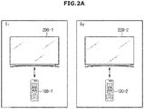
- FIGS. 2A and 2B are views illustrating a pairing relation between control devices and display apparatuses.
- a plurality of display apparatuses 200 e.g., 200-1, 200-2, 200-3, are provided in a certain area, and the plurality of display apparatuses 200 may be connected to each other through wireless communication.
- the certain area is an area in which the plurality of display apparatuses 200 can be connected through wireless communication.
- the plurality of display apparatuses 200 may be separately provided in a plurality of separated spaces.
- the plurality of display apparatuses 200 may include a first display apparatus 200-1 and a second display apparatus 200-2, the first display apparatus 200-1 may be provided in a first space S1, and the second display apparatus 200-2 may be provided in a second space S2.
- the plurality of display apparatuses 200 may include the first display apparatus 200-1, the second display apparatus 200-2, and a third display apparatus 200-3, the first display apparatus 200-1 may be provided in the first space S1, the second display apparatus 200-2 may be provided in the second space S2, and the third display apparatus 200-3 may be provided in a third space S3.
- FIGS. 2A and 2B are only examples, and the number of the display apparatuses 200 is not limited thereto.
- the plurality of display apparatuses 200 may form a one-to-one pairing relation with the control devices 100, and each display apparatus 200 may be controlled by the control device 100 paired therewith.
- the first display apparatus 200-1 is paired with the first control device 100-1 which is located in the same area in which the first display apparatus 200-1 is located, and the second display apparatus 200-2 is paired with the second control device 100-2 which is located in the same area in which the second display apparatus 200-2 is located.
- the first display apparatus 200-1 may be controlled by the first control device 100-1
- the second display apparatus 200-2 may be controlled by the second control device 100-2.
- user commands input to the first control device 100-1 are transmitted to the first display apparatus 200-1, and the first display apparatus 200-1 operates based on the user commands input to the first control device 100-1.
- user commands input to the second control device 100-2 are transmitted to the second display apparatus 200-2, and the second display apparatus 200-2 operates based on the user commands input to the second control device 100-2.
- the first display apparatus 200-1 is paired with the first control device 100-1 which is located in the same area in which the first display apparatus 200-1 is located
- the second display apparatus 200-2 is paired with the second control device 100-2 which is located in the same area in which the second display apparatus 200-2 is located
- the third display apparatus 200-3 is paired with the third control device 100-3 which is located in the same area in which the third display apparatus 200-3 is located.
- the first display apparatus 200-1 may be controlled by the first control device 100-1
- the second display apparatus 200-2 may be controlled by the second control device 100-2
- the third display apparatus 200-3 may be controlled by the third control device 100-3.
- user commands input to the first control device 100-1 are transmitted to the first display apparatus 200-1
- the first display apparatus 200-1 operates according to the user commands input to the first control device 100-1
- User commands input to the second control device 100-2 are transmitted to the second display apparatus 200-2
- the second display apparatus 200-2 operates according to the user commands input to the second control device 100-2
- user commands input to the third control device 100-3 are transmitted to the third display apparatus 200-3
- the third display apparatus 200-3 operates according to the user commands input to the third control device 100-3.
- each of the display apparatuses 200 may be controlled by the control device 100 paired therewith.
- a display apparatus 200 and a control device 100 paired therewith are not located in the same space, or a display apparatus 200 and a control device 100 paired with a different display apparatus 200 are located in the same location, it may be necessary for the corresponding display apparatus 200 to be controlled by the control device 100 paired with a different display apparatus 200.
- the second display apparatus 200-2 may need to be controlled by the first control device 100-1.
- a process of re-pairing the control device 100 paired with the different display apparatus 200 with the corresponding display apparatus 200 may be performed.
- the control system 1 of the display apparatus that is formed to be controllable by a control device 100 paired with a different display apparatus 200, without requiring a re-pairing process to be performed will be described with reference to an accompanying block diagram.
- a display apparatus 200 to be controlled is defined as “a target display apparatus 200,” and a display apparatus 200 located peripherally relative to the target display apparatus 200, for example, located in a certain area from the target display apparatus 200 and performing wireless communication with the target display apparatus 200 is defined as “a peripheral display apparatus 200,” and even if a control device 100 is paired with a display apparatus 200 other than the target display apparatus 200, the control device 100 which is operated by a user to control a target display apparatus 200 is defined as "a target control device 100.”
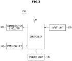
- FIG. 3 is a block diagram illustrating a control device
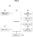
- FIG. 4 is a block diagram illustrating a display apparatus.
- the control device 100 may include a power supply 110, communication circuitry in the form of, for example, a communication unit 120, a controller 130, a storage unit 140, and an input unit 150
- the display apparatus 200 may include a power supply 210, communication circuitry in the form of, for example, a communication unit 220, a controller 230, a storage unit 240, and a user interface unit 250.
- the control device 100 may be a target control device 100
- the display apparatus 200 may be a target display apparatus 200.
- the power supply 110 supplies driving power to drive the control device 100.
- the power supply 110 may be implemented by a battery which is electrically connected to various components mounted on the control device 100 and supply driving power.
- the power supply 110 may be implemented by a primary battery, for example, a mercury battery, a manganese battery, an alkaline battery, and a lithium battery, and also a secondary battery, for example, a Ni-Cd battery, a Ni-NH battery, a lead acid storage battery, a Li-ion battery, a lithium polymer battery.
- the power supply 110 may also be implemented by a solar battery which generates electricity using solar heat, but is not limited to that type.
- the input unit 150 receives user commands.
- the input unit 150 receives various commands from a user to operate the display apparatus 200.
- the input unit 150 may receive on/off commands, channel/volume control commands, screen control commands, function selection commands, menu moving/selection commands or the like from a user, and since the implementation type of the input unit 150 has been described above, it will be omitted below.
- the controller 130 is configured to control overall operations of the control device 100.
- the controller 130 is supplied with power of the power supply 110, and is configured to control an operation of each unit of the control device 100, for example, the communication unit 120 and the storage unit 140.
- the controller 130 may be configured to control the storage unit 140 to store information of the display apparatus 200 paired with the control device 100.
- the controller 130 may also be configured to control the storage unit 140 to store a user command input through the input unit 150.
- controller 130 may be configured to convert a user command input through the input unit 150 into a form of data which is receivable by the display apparatus 200, and may be configured to control the communication unit 120 to transmit the user command converted into the form of data to the display apparatus 200.
- the controller 130 may be configured to control the communication unit 120 to transmit the user command converted into the form of data to the paired display apparatus 200.
- the controller 130 may be configured to convert a user command into Bluetooth data, and to control the communication unit 120 to transmit the user command which is converted into the Bluetooth data to the paired display apparatus 200.
- the controller 130 may be configured to control the communication unit 120 to transmit a format-converted user command to the target display apparatus 200.
- the specific description of the control priority change of the control device 100 will be described below along with the description of the display apparatus 200.
- a user command which is converted into the form of data receivable by the display apparatus 200 for example, Bluetooth data
- an operation command hereinafter.
- the controller 130 may be configured to control the communication unit 120 to transmit an operation attempt signal to the target display apparatus 200.
- the controller 130 may be configured to control the communication unit 120 to transmit the operation command to the paired display apparatus 200, and to simultaneously transmit the operation attempt signal to the target display apparatus 200.
- the communication unit 120 may be configured to transmit an operation command to the paired display apparatus 200 based on a control signal of the controller 130, and to simultaneously transmit an operation attempt signal to the target display apparatus 200.
- an 'operation attempt signal' may, for example, be referred to as a signal which indicates that a user is attempting to operate the target control device 100 to control the target display apparatus 200, and when the control device 100 and the display apparatus 200 perform IR communication, the operation attempt signal may include an IR signal, but is not limited thereto.
- the above-described controller 130 may, for example, be formed of various processors including at least one chip in which an integrated circuit is formed.
- the controller 130 may, for example, be formed of one processor, but may also be provided as a plurality of separate processors.
- the communication unit 120 is configured to perform wireless communication with the display apparatus 200.
- the communication unit 120 performs wireless communication with the paired display apparatus 200, and performs wireless communication with the display apparatus 200 located in the same area, for example, the target display apparatus 200.
- the communication unit 120 may transfer or receive data to or from the paired display apparatus 200.
- the communication unit 120 may receive information of the paired display apparatus 200.
- the communication unit 120 may transmit an operation command based on a user input to the paired display apparatus 200.
- the communication unit 120 may transmit or receive data to or from the paired display apparatus 200 using, for example, a Bluetooth method, and in this case, the operation command may include Bluetooth data.
- a communication method between the communication unit 120 and the display apparatus 200 paired therewith is not limited to a Bluetooth method, and a type of the operation command is not limited to Bluetooth data.
- the communication unit 120 may transmit an operation attempt signal based on a user input to the target display apparatus 200.
- the communication unit 120 may perform, for example, IR communication with the target display apparatus 200, and in this case, the operation attempt signal may include an 'IR signal.'
- a communication method between the communication unit 120 and the target display apparatus 200 is not limited to the IR communication, and a type of the operation attempt signal is not limited to the IR signal.
- the communication unit 120 may transmit an operation command based on a user input to the target display apparatus 200.
- An apparatus which receives the operation command of the communication unit 120 may be changed from the paired display apparatus 200 to the target display apparatus 200. For example, based on a change of the control priority of the control device 100, the communication unit 120 may transmit the operation command to the target display apparatus 200, or the target display apparatus 200 may receive the operation command of the communication unit 120.
- the communication method for transmitting the operation command and the communication method for transmitting the operation attempt signal may be different from each other, for example, a Bluetooth method and an IR method, or the same method may be used.
- the communication unit 120 may include various communication modules, for example, a wireless Internet module, a near field communication module, a mobile communication module, etc.
- the wireless Internet module is a module which is connected to an outside network and performs communication based on a communication protocol, for example, wireless LAN (WLAN), Wi-Fi, Wireless Broadband (WiBro), Worldwide Interoperability for Microwave Access (WiMAX), High-Speed Downlink Packet Access (HSDPA), etc.
- a communication protocol for example, wireless LAN (WLAN), Wi-Fi, Wireless Broadband (WiBro), Worldwide Interoperability for Microwave Access (WiMAX), High-Speed Downlink Packet Access (HSDPA), etc.
- the near field communication module may be a module for performing communication with outside devices located adjacent to each other based on a near field communication method, for example, Bluetooth, radio frequency identification (RFID), Infrared Data Association (IrDA) communication, ultra wideband (UWB), ZigBee and the like.
- RFID radio frequency identification
- IrDA Infrared Data Association
- UWB ultra wideband
- ZigBee ZigBee
- the mobile communication module is a module which accesses a mobile communication network and performs communication based on various mobile communication protocols, for example, third generation (3G), Third Generation Partnership Project (3GPP), Long Term Evolution (LTE), etc.
- 3G third generation
- 3GPP Third Generation Partnership Project
- LTE Long Term Evolution
- the present invention is not limited thereto, and as long as the communication unit 120 can communicate with the display apparatus 200, the communication unit 120 may adopt other types of communication modules in addition to the modules described above.
- the storage unit 140 may temporarily or permanently store data and programs to operate the control device 100.
- the storage unit 140 may store information of the paired display apparatus 200, and may temporarily or permanently store user commands or operation commands input through the input unit 150.
- the storage unit 140 may store programs to convert the input user commands into operation commands that the display apparatus 200 may receive and analyze, and transfer the operation commands and operation attempt signals.
- the storage unit 140 described above may include at least one type of storage medium, for example, a flash memory type, a hard disk type, a multimedia card micro type, a cart type memory such as a Secure Digital (SD) or extreme digital (XD) memory, a random access memory (RAM), a static RAM (SRAM), a read-only memory (ROM), an electrically erasable programmable ROM (EEPROM), a programmable ROM (PROM), a magnetic RAM (MRAM), a magnetic disk, an optical disc, etc.
- SD Secure Digital
- XD extreme digital
- RAM random access memory
- SRAM static RAM
- ROM read-only memory
- EEPROM electrically erasable programmable ROM
- PROM programmable ROM
- MRAM magnetic RAM
- the present invention is not limited thereto, and may be implemented using different types known in the art.
- the control device 100 may use web storages which perform a storage function on the Internet.
- the power supply 210 is supplied with external power or internal power, and supplies driving power to operate the display apparatus 200.
- the power supply 210 is electrically connected to each unit of the display apparatus 200, for example, the communication unit 220, the controller 230, the user interface unit 250, and the storage unit 240, and supplies the driving power thereto.
- the power supply 210 may be implemented by a primary battery, for example, a mercury battery, a manganese battery, an alkaline battery, and a lithium battery, and also a secondary battery such as a Ni-Cd battery, a Ni-NH battery, a lead acid storage battery, a Li-ion battery, or a lithium polymer battery.
- the power supply 210 may be implemented by a solar battery which generates electricity using solar heat, but is not limited to that type.
- a user may connect the display apparatus 1 and the external power supply using a wire, and charge the power supply 210.
- the controller 230 is configured to control overall operations of the display apparatus 200.
- the controller 230 is supplied with power from the power supply 210, and is configured to control each unit of the display apparatus 200, for example, the communication unit 220, the storage unit 240, the display unit 252, and the audio output unit 253.
- the controller 230 may be configured to control the communication unit 220 to transmit, receive, or share pairing information with the different display apparatus 200.
- the pairing information may include identification information of the paired control device 100.
- the controller 230 of the first display apparatus 200-1 may be configured to control the communication unit 220 to transmit identification information of the first control device 100-1, for example, the identification information of the control device 100-1 paired with the first display apparatus 200-1, to a different display apparatus, for example, the second display apparatus 200-2.
- the controller 230 of the second display apparatus 200-2 may be configured to control the communication unit 220 to transmit identification information of the second control device 100-2, for example, the identification information of the control device 100-2 paired with the second display apparatus 200-2, to the first display apparatus 200-1.
- the controller 230 of the first display apparatus 200-1 may be configured to control the communication unit 220 to transmit identification information of the first control device 100-1, for example, the identification information of the control device 100-1 paired with the first display apparatus 200-1, to a different display apparatus, for example, the second display apparatus 200-2 and the third display apparatus 200-3.
- the controller 230 of the second display apparatus 200-2 may be configured to control the communication unit 220 to transmit identification information of the second control device 100-2, for example, the identification information of the second control device 100-2 paired with second display apparatus 200-2, to the first display apparatus 200-1 and the third display apparatus 200-3.
- the controller 230 of the third display apparatus 200-3 may be configured to control the communication unit 220 to transmit identification information of the third control device 100-3, for example, the identification information of the third control device 100-3 paired with the display apparatus 200-3, to the first display apparatus 200-1 and the second display apparatus 200-2.
- the controller 230 is configured to control the communication unit 220 to transmit to the peripheral display apparatus 200 a request message requesting determination on whether an operation command is received.
- the controller 230 may be configured to identify the target control device 100 based on the response message, change a control priority of the target control device 100 to the highest priority, and be controlled by the target control device 100.
- the controller 230 may be configured to generate an identification information list of the control device 100 based on pairing information received from the peripheral display apparatus 200, change a priority of identification information of the target control device 100 to the highest priority in the identification information list, and change a control priority of the target control device 100 to the highest priority. This will be described below.
- the identification information list representing a list of the identification of control devices, ranked according to priority, will also be referred to herein as a "priority list".
- the controller 230 may be configured to sequentially or "cyclically" perform a priority change of the priority list, and identify the target control device 100. Identification of the target control device 100 will be described below.
- the control priority of the target control device 100 may be changed to the highest priority, or the target control device 100 is identified, and the operation command of the target control device 100 may be received through the communication unit 220.
- the controller 230 may be configured to perform an operation or function corresponding to the received operation command.
- the controller 230 may be configured to control, for example, a display unit 252 or an audio output unit 253 based on operation commands.
- an operation command includes a "channel change command”
- the controller 230 may be configured to control the display unit 252 to output a screen of the changed channel.
- the controller 230 may be configured to control the audio output unit 253 to output sound at the adjusted volume.
- the controller 230 may be configured to control the communication unit 220 to transmit to the target display apparatus 200 a response message to the request message described above.
- the controller 230 may be configured to control the storage unit 240 to store pairing information received from the different display apparatus 200.
- the controller 230 may be configured to control the storage unit 240 to generate a priority list of the control devices 100 based on the identification information of the control devices and the pairing information, and store the generated priority list.
- the controller 230 may be configured to control the storage unit 240 to store the revised priority list based on the changing of the priority.
- the controller 230 described above may, for example, be formed of various processors including at least one chip in which an integrated circuit is formed.
- the controller 230 may, for example, be provided in one processor, or may be provided as a plurality of separate processors.
- the communication unit 220 may be configured to perform communication with external servers or external devices of various types, and transmit or receive various signals or information based on various communication methods.
- the communication unit 220 may receive image data or audio data to be output to the user interface unit 250, for example, through the display unit 252 or the audio output unit 253, from broadcasting servers or mobile communication servers.
- the communication unit 220 may perform wireless communication with the control device 100 and a different display apparatus 200.
- the communication unit 220 may receive an operation attempt signal from the target control device 100.
- the communication unit 220 may transmit to the peripheral display apparatus 200 a request message requesting determination on whether an operation command is received, and may receive a response message to the request message from the peripheral display apparatus 200.
- a change in the priority list is performed, and the communication unit 220 may receive the operation command from the target control device 100.
- the communication unit 220 When the communication unit 220 is included in the peripheral display apparatus 200, for example, when the communication unit 220 is included in the display apparatus 200 paired with the target control device 100, the communication unit 220 may receive an operation command from the target control device 100. In addition, the communication unit 220 included in the peripheral display apparatus 200 may receive the request message described above from the target display apparatus 200, and may transmit a response message to the request message to the target display apparatus 200.
- the communication unit 220 may include various communication modules, for example, broadcast receiving modules, wireless Internet modules, near field communication modules, mobile communication modules, etc.
- a broadcast receiving module may include terrestrial broadcast receiving modules including antennas, demodulators, equalizer and the like to receive terrestrial broadcasting signals, digital multimedia broadcasting (DMB) modules to receive and process DMB signals, and the like. Since the wireless Internet module, the near field communication module, and the mobile communication module are the same as those described above, descriptions will be omitted below.
- DMB digital multimedia broadcasting
- the present invention is not limited thereto, and as long as the control device 100 and the different display apparatus 200 can perform communication with external devices or external servers, the communication unit 220 may adopt other types of communication modules in addition to the communication modules described above.
- the storage unit 240 may temporarily or permanently store data and programs to operate the display apparatus 200.
- the storage unit 240 may temporarily or permanently store image data or audio data received from an outside device or an outside server.
- the storage unit 240 may store pairing information received from the different display apparatus 200.
- the storage unit 240 may store a priority list of the control device 100 generated based on the pairing information, and when a priority change is performed, the storage unit 240 may store the priority list revised based on the changing of the priority.
- the storage unit 240 may store a program to transmit a request message, and when a request message is received, the storage unit 240 may store a program for transmitting a response message, a program for identifying the target control device 100 based on the response message, or the like. In addition, the storage unit 240 may store a program for generating a priority list of the control device 100 based on pairing information, a program for renewing or revising the priority list based on the priority change, or the like.
- the storage unit 240 described above may include at least one type of storage medium, for example, a flash memory type, a hard disk type, a multimedia card micro type, a card type memory such as an SD or XD memory, a RAM, an SRAM, a ROM, an EEPROM, a PROM, an MRAM, a magnetic disk, and an optical disc.
- a flash memory type for example, a flash memory type, a hard disk type, a multimedia card micro type, a card type memory such as an SD or XD memory, a RAM, an SRAM, a ROM, an EEPROM, a PROM, an MRAM, a magnetic disk, and an optical disc.
- the display apparatus 200 may use web storages which perform a storage function on the Internet.
- control system 1 of the display apparatus was described above with reference to the control block diagram, and the operation of the control system 1 of the display apparatus will be described hereinafter with reference to FIGS. 5 to 19 .
- FIGS. 5 to 10 are views illustrating example operation of a control system of a display apparatus.
- the display apparatus 200 and the control device 100 are the same as illustrated in FIG. 2A .
- the display apparatus 200 includes the first display apparatus 200-1 provided in the first space Si and the second display apparatus 200-2 provided in the second space S2, the first display apparatus 200-1 is paired with the first control device 100-1, and the second display apparatus 200-2 is paired with the second control device 100-2.
- FIG. 5 is a view illustrating an example in which a control device which is paired with a peripheral display apparatus becomes a target control device
- FIG. 6 is view illustrating pairing information stored in the display apparatus in FIG. 5
- FIG. 7 is a view illustrating priority lists stored in the display apparatus in FIG. 5 .
- FIG. 5 illustrates the first control device 100-1 which is paired with the first display apparatus 200-1, is located in the same area as the second display apparatus 200-2, and is operated by a user to control the second display apparatus 200-2.
- the second display apparatus 200-2 becomes a display apparatus to be controlled, for example, a target display apparatus
- the first control device 100-1 paired with the first display apparatus 200-1 becomes a target control device to be controlled by the user.
- the first display apparatus 200-1 may search for a different display apparatus located in a certain area, for example, the area of the second display apparatus 200-2, through the communication unit 220, and may transmit, receive, and share pairing information with the located second display apparatus 200-2.
- the second display apparatus 200-2 may search for a different display apparatus located in a certain area, for example, the area of the first display apparatus 200-1, through the communication unit 220, and may transmit, receive, and share the pairing information with the located first display apparatus 200-1.
- Sharing of pairing information between the first display apparatus 200-1 and the second display apparatus 200-2 may be performed before an operation of the target control device 100-1 is performed, and the pairing information may be stored in the first display apparatus 200-1 and the second display apparatus 200-2.
- pairing information may include identification information of the paired control device 100.
- the pairing information may include identification information of the first control device 100-1 paired with the first display apparatus 200-1 and identification information of a second control device 100-2 paired with the second display apparatus 200-2.
- the storage unit 240 of the first display apparatus 200-1 and the storage unit 240 of the second display apparatus 200-2 may each store pairing information as illustrated in FIG. 6 .
- the storage unit 240 of the first display apparatus 200-1 may store a Bluetooth device address (BD_ADDR) of the first control device 100-1 paired with the first display apparatus 200-1 corresponding to the first display apparatus 200-1, and may store a BD_ADDR of the second control device 100-2 paired with the second display apparatus 200-2 corresponding to the second display apparatus 200-2.
- the storage unit 240 of the second display apparatus 200-2 may also store a BD_ADDR of the first control device 100-1 paired with the first display apparatus 200-1 corresponding to the first display apparatus 200-1, and may store a BD_ADDR of the second control device 100-2 paired with the second display apparatus 200-2 corresponding to the second display apparatus 200-2.
- the first display apparatus 200-1 and the second display apparatus 200-2 may generate and store a priority list of the control device 100 based on the pairing information.
- the controller 230 of the first display apparatus 200-1 may be configured to generate a priority list based on identification information and the pairing information so that a control priority of the first control device 100-1 paired with the first display apparatus 200-1 is the highest priority, and the generated priority list may be stored in the storage unit 240.
- the storage unit 240 of the first display apparatus 200-1 may store the priority list in which a BD_ADDR of the first control device 100-1 has the first priority.
- the controller 230 of the second display apparatus 200-2 may be configured to generate a priority list based on identification information and the pairing information so that a control priority of the second control device 100-2 paired with the second display apparatus 200-2 is the highest priority, and the generated priority list may be stored in the storage unit 240.
- the storage unit 240 of the second display apparatus 200-2 may store a priority list in which a BD_ADDR of the second control device 100-2 has the first priority.
- the communication unit 120 of the target control device 100-1 transmits an operation attempt signal to a target display apparatus located in the same area, for example, the second display apparatus 200-2, and transmits an operation command to the first display apparatus 200-1 paired with the target control device 100-1.
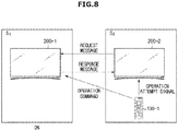
- FIG. 8 is a view illustrating an operation of the target display apparatus illustrated, for example, in FIG. 5 when an operation attempt signal is received.
- the target display apparatus 200-2 that has received an operation attempt signal transmits to the peripheral display apparatus which shares pairing information, for example, the first display apparatus 200-1, a request message requesting a determination of whether the operation command is received.
- the communication unit 220 of the first display apparatus 200-1 may transmit a response message to the request message to the target display apparatus 200-2.
- the communication unit 220 of the first display apparatus 200-1 may transmit the response message which informs the target display apparatus 200-2 of receipt of the operation command.
- the controller 230 of the target display apparatus 200-2 is configured to identify the target control device 100-1 based on the response message of the peripheral display apparatus, for example, the first display apparatus 200-1, and changes a priority of identification information of the target control device 100-1 to the highest priority in a priority list.
- the priority list renewed or revised based on the changing of the priority may be stored in the storage unit 240 of the target display apparatus 200-2.
- FIG. 9 is a view illustrating a renewed or revised priority list of a target display apparatus.
- the controller 230 of the target display apparatus 200-2 may be configured to confirm that a target control device is the first control device 100-1 paired with the first display apparatus based on the response message of the first display apparatus 200-1. Once the target control device is identified, the controller 230 changes a BD_ADDR of the first control device 100-1 paired with the first display apparatus 200-1 to the highest priority in a priority list based on identification information and pairing information stored in the storage unit 240, and as illustrated in FIG. 9 , the storage unit 240 of the target display apparatus 200-2 stores the renewed or revised priority list.
- the target display apparatus 200-2 may then be controlled by the target control device 100-1.
- an operation command of the target control device 100-1 is received by the target display apparatus 200-2, and the target display apparatus 200-2 performs a function based on the received operation command.
- FIG. 10 is a view illustrating an operation of a target display apparatus when a peripheral display apparatus is off.
- the target display apparatus 200-2 that has received an operation attempt signal transmits to a peripheral display apparatus which shares pairing information, for example, the first display apparatus 200-1, a request message requesting determination on whether an operation command is received.
- the first display apparatus 200-1 may not transmit a response message to the request message to the target display apparatus 200-2.
- the controller 230 of the target display apparatus 200-2 may be configured to sequentially change a priority of identification information in a priority list generated in advance.
- the controller 230 is configured to change identification information of the second priority, for example, a BD_ADDR of the first control device 100-1, to the first priority.
- the controller 230 of the target display apparatus 200-2 may be configured to determine whether the operation command is received through the communication unit 220, and when the operation command is received, the controller 230 of the target display apparatus 200-2 may be configured to control the storage such that the identification information list based on the changing of the priority is stored, and may identify the target control device 100-1.
- the communication unit 220 of the target display apparatus 200-2 may receive the operation command.
- the storage unit 240 of the target display apparatus 200-2 stores the priority list in which the BD_ADDR of the first control device 100-1 is changed to the first priority, for example, the same priority list as illustrated in FIG. 9 .
- controller 230 may be configured to compare the pairing information and the renewed or revised priority list, determine whether identification information of the first priority is the BD_ADDR of the first control device 100-1, and confirm that the target control device is the first control device 100-1 which was paired with the first display apparatus 200-1.
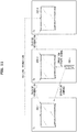
- FIGS. 11 to 19 are views illustrating an operation of a control system of a display apparatus.
- a display apparatus 200 and a control device 100 are the same as illustrated in FIG. 2B .
- FIGS. 11 to 19 illustrate that the display apparatus 200 includes a first display apparatus 200-1 provided in a first space Si, a second display apparatus 200-2 provided in a second space S2, and a third display apparatus 200-3 provided in a third space S3, the first display apparatus 200-1 is paired with a first control device 100-1, the second display apparatus 200-2 is paired with a second control device 100-2, and the third display apparatus 200-3 is paired with a third control device 100-3.
- FIG. 11 illustrates another example in which a control device which is paired with a peripheral display apparatus becomes a target control device
- FIG. 12 illustrates pairing information stored in the display apparatus in FIG. 11
- FIG. 13 illustrates a priority list stored in the display apparatus in FIG. 11 .
- the first control device 100-1 which is paired with the first display apparatus 200-1 is located in the same area as the second display apparatus 200-2, and is operated by a user to control the second display apparatus 200-2.
- the second display apparatus 200-2 becomes a display apparatus to be controlled, for example, a target display apparatus
- the first control device 100-1 paired with the first display apparatus 200-1 becomes a target control device to be controlled by the user.
- the first display apparatus 200-1 may search for a different display apparatus located in a certain area, for example, the second display apparatus 200-2 and the third display apparatus 200-3, through the communication unit 220, and transmit, receive, and share pairing information with the located second display apparatus 200-2 and third display apparatus 200-3.
- the second display apparatus 200-2 may search for a different display apparatus located in a certain area, for example, the first display apparatus 200-1 and the third display apparatus 200-3, through the communication unit 220, and transmit, receive, and share pairing information with the located first display apparatus 200-1 and third display apparatus 200-3.
- the third display apparatus 200-3 may also search for a different display apparatus located in a certain area, for example, the first display apparatus 200-1 and the second display apparatus 200-2, through the communication unit 220, and transmit, receive, and share pairing information with the located first display apparatus 200-1 and second display apparatus 200-2.
- Sharing of pairing information among the first display apparatus 200-1, the second display apparatus 200-2, and the third display apparatus 200-3 may be performed before an operation of the target control device 100-1, and the pairing information may be stored in each of the first display apparatus 200-1, the second display apparatus 200-2, and the third display apparatus 200-3.
- the pairing information may include identification information of the first control device 100-1 paired with the first display apparatus 200-1, identification information of the second control device 100-2 paired with the second display apparatus 200-2, and identification information of the third control device 100-3 paired with the third display apparatus 200-3.
- the storage unit 240 of the first display apparatus 200-1, the storage unit 240 of the second display apparatus 200-2, and the storage unit 240 of the third display apparatus 200-3 may each store pairing information as illustrated, for example, in FIG. 12 .
- the storage unit 240 of the first display apparatus 200-1 may store a BD_ADDR of the first control device 100-1 paired with the first display apparatus 200-1 corresponding to the first display apparatus 200-1, a BD_ADDR of the second control device 100-2 paired with the second display apparatus 200-2 corresponding to the second display apparatus 200-2, and a BD_ADDR of the third control device 100-3 paired with the third display apparatus 200-3 corresponding to the third display apparatus 200-3.
- the storage unit 240 of the second display apparatus 200-2 and the storage unit 240 of the third display apparatus 200-3 may each store the BD_ADDR of the first control device 100-1 paired with the first display apparatus 200-1 corresponding to the first display apparatus 200-1, the BD_ADDR of the second control device 100-2 paired with the second display apparatus 200-2 corresponding to the second display apparatus 200-2, and the BD_ADDR of the third control device 100-3 paired with the third display apparatus 200-3 corresponding to the third display apparatus 200-3.
- the first display apparatus 200-1, the second display apparatus 200-2, and the third display apparatus 200-3 may each generate and store a priority list of the identification information of control devices 100 based on pairing information.
- the controller 230 of the first display apparatus 200-1 may be configured to generate a priority list based on pairing information so that a control priority of the first control device 100-1 paired with the first display apparatus 200-1 becomes the highest priority, and the generated priority list may be stored in the storage unit 240.
- the storage unit 240 of the first display apparatus 200-1 may store the priority list in which a BD_ADDR of the first control device 100-1 has the first priority.
- the controller 230 of the second display apparatus 200-2 may be configured to generate a priority list based on pairing information so that a control priority of second control device 100-2 paired with the second display apparatus 200-2 becomes the highest priority, and the generated priority list may be stored in the storage unit 240.
- the storage unit 240 of the second display apparatus 200-2 may store the priority list in which a BD_ADDR of the second control device 100-2 has the first priority.
- the controller 230 of the third display apparatus 200-3 may be configured to generate a priority list based on pairing information so that a control priority of third control device 100-3 paired with the third display apparatus 200-3 becomes the highest priority, and the generated priority list may be stored in the storage unit 240.
- the storage unit 240 of the third display apparatus 200-3 may store the priority list in which a BD_ADDR of the third control device 100-3 has the first priority.
- the communication unit 120 of the target control device 100-1 transmits an operation attempt signal to a target display apparatus located in the same area, for example, the second display apparatus 200-2, and transmits an operation command to the first display apparatus 200-1 paired with the target control device 100-1.
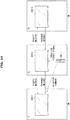
- FIG. 14 illustrates an operation of a target display apparatus according to FIG. 11 when an operation attempt signal is received.
- the target display apparatus 200-2 which received the operation attempt signal transmits to a peripheral display apparatus, for example, the first display apparatus 200-1 and the third display apparatus 200-3 which share pairing information, a request message requesting a determination of whether an operation command is received.
- the communication unit 220 of the first display apparatus 200-1 may transmit a response message to the request message to the target display apparatus 200-2.
- the communication unit 220 of the first display apparatus 200-1 may transmit the response message which informs the target display apparatus 200-2 of receipt of the operation command.
- the communication unit 220 of the third display apparatus 200-3 may transmit a response message to the request message to the target display apparatus 200-2.
- the communication unit 220 of the third display apparatus 200-3 may transmit the response message which informs the target display apparatus 200-2 of 'no receipt of the operation command.
- the controller 230 of the target display apparatus 200-2 is configured to identify the target control device 100-1 based on the response messages of the peripheral display apparatus, for example, the first display apparatus 200-1 and the third display apparatus 200-3, and to change a priority of identification information of the target control device 100-1 to the highest priority in a priority list.
- the priority list is renewed or revised based on the changing of the priority may be stored in the storage unit 240 of the target display apparatus 200-2.
- FIG. 15 is a view illustrating a renewed or revised priority list of a target display apparatus.
- the controller 230 of the target display apparatus 200-2 may be configured to confirm that a display apparatus which received the operation command is the first display apparatus 200-1 based on the response message of the first display apparatus 200-1 and the third display apparatus 200-3.
- the controller 230 may be configured to determine that a target control device is the first control device 100-1 paired with the first display apparatus.
- the controller 230 may be configured to change a BD_ADDR of the first control device 100-1 paired with the first display apparatus 200-1 to the highest priority in a priority list based on the pairing information stored in the storage unit 240, and as illustrated in FIG. 15 , the storage unit 240 of the target display apparatus 200-2 may store the priority list having the changed priority.
- the target display apparatus 200-2 may be controlled by the target control device 100-1.
- the operation command of the target control device 100-1 is received by the target display apparatus 200-2, and the target display apparatus 200-2 performs a function based on the received operation command.
- FIGS. 16 and 17 are views illustrating an operation of a target display apparatus when a peripheral display apparatus is off.
- the target display apparatus 200-2 that has received an operation attempt signal transmits to peripheral display apparatuses which share pairing information, for example, the first display apparatus 200-1 and the third display apparatus 200-3, a request message requesting determination on whether an operation command is received.
- the communication unit 220 of the first display apparatus 200-1 may transmit a response message to the request message to the target display apparatus 200-2.
- the communication unit 220 of the third display apparatus 200-3 may not transmit the response message to the request message to the target display apparatus 200-2.
- the communication unit 220 of the target display apparatus 200-2 receives the response message which informs of receipt of the operation command' from the first display apparatus 200-1, but does not receive the response message from the third display apparatus 200-3.
- the controller 230 of the target display apparatus 200-2 may be configured to determine that a display apparatus that has received the operation command is the first display apparatus 200-1 based on the response message of the first display apparatus 200-1, and a target control device is the first control device 100-1 paired with the first display apparatus.
- the communication unit 220 of the first display apparatus 200-1 may not transmit a response message to the request message to the target display apparatus 200-2.
- the communication unit 220 of the third display apparatus 200-3 may transmit a response message to the request message to the target display apparatus 200-2.
- the communication unit 220 of the target display apparatus 200-2 does not receive a response message from the first display apparatus 200-1, but receives a response message which informs of 'no receipt of the operation command' from the third display apparatus 200-3.
- the controller 230 of the target display apparatus 200-2 may be configured to confirm that the third display apparatus 200-3 does not receive the operation command, for example, a display apparatus that has received the operation command is the first display apparatus 200-1, based on the response message of the third display apparatus 200-3, and that the target control device is the first control device 100-1 paired with first display apparatus.
- the controller 230 may be configured to change a BD_ADDR of the first control device 100-1 paired with the first display apparatus 200-1 to the highest priority in a priority list based on the pairing information stored in the storage unit 240.
- the target display apparatus 200-2 may be controlled by the target control device 100-1.
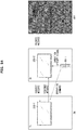
- FIG. 18 is a view illustrating an operation of a target display apparatus when all peripheral display apparatuses are off
- FIG. 19 is a view illustrating a sequential or "cyclic" change of priorities of a number of identification information.
- the communication unit 220 of the target display apparatus 200-2 does not receive a response message from the peripheral display apparatuses 200-1 and 200-3.
- the controller 230 of the target display apparatus 200-2 may be configured to sequentially change a priority of identification information in a priority list which was generated in advance. While the priority of the identification information is changed sequentially, the controller 230 of the target display apparatus 200-2 may be configured to determine through the communication unit 220 whether an operation command is received, and when the operation command is received, the controller 230 of the target display apparatus 200-2 is configured to control the storage such that the renewed or revised priority is stored.
- the controller 230 changes an identification information of the second priority, for example, a BD_ADDR of the third control device 100-3, to the first priority, and renews or revises the priority list as illustrated in FIG. 19A .
- the BD_ADDR of the third control device 100-3 is changed to the first priority, the communication unit 220 of the target display apparatus 200-2 is still unable to receive the operation command, and the controller 230 is configured to change the priority again.
- the controller 230 is configured to change identification information of the second priority in the renewed priority list, for example, a BD_ADDR of the first control device 100-1, to the first priority, and renews or revises the priority list as illustrate in FIG. 19B .
- the communication unit 220 of the target display apparatus 200-2 may receive the operation command.
- the storage unit 240 of the target display apparatus 200-2 may store the priority list in which the BD_ADDR of the first control device 100-1 is changed to the first priority, for example, the renewed priority list as illustrated in FIG.
- the controller 230 may be configured to compare pairing information and the renewed priority list, confirm that the identification information of the first priority is the BD_ADDR of the first control device 100-1, and identify that the target control device is the paired first control device 100-1 paired with the first display apparatus 200-1.
- the display apparatus 200, the control device 100, and the control system 1 of the display apparatus including the same were described above, and a control method of a display apparatus will be described hereinafter with reference to an accompanying flow chart.
- FIG. 20 is a flow chart illustrating a control method of a display apparatus.
- the target display apparatus 200 receives pairing information from the peripheral display apparatuses 200, or shares the pairing information with the peripheral display apparatuses 200 (S710).
- Sharing of pairing information with the peripheral display apparatuses 200 is performed before an operation of the target control device 100-1, and the pairing information is stored in the target display apparatus 200.
- the target display apparatus 200 generates a priority list for the control devices 100 based on identification information of the control devices derived from the pairing information, and stores the generated priority list.
- the target display apparatus 200-2 receives an operation attempt signal from the target control device 100 (S720).
- the target display apparatus 200-2 that has received the operation attempt signal transmits to the peripheral display apparatuses which share the pairing information a request message requesting a determination of whether an operation command is received (S730). Next, the target display apparatus 200-2 determines whether response messages to the request message are received from the peripheral display apparatuses 200 (S740).
- the target display apparatus 200-2 obtains identification information of the target control device 100 based on the response messages and the pairing information (S751).
- the target display apparatus 200-2 identifies what display apparatus 200 was paired with the target control device 100 based on the response messages, and obtains the identification information of the target control device 100 based on the pairing information.
- the target display apparatus 200-2 then changes a priority of the identification information of the target control device 100 in the priority list to the highest priority (S752). As the identification information of the target control device 100 is changed to the highest priority, the operation command of the target control device 100 is received by the target display apparatus 200. In addition, the changed priority list may be stored in the target display apparatus 200.
- the target display apparatus 200 performs a function or an operation corresponding to the received operation command (S770).
- the target display apparatus 200 may be controlled by the target control device 100.
- the target display apparatus 200 sequentially changes the priority information of the control devices 100 paired with the peripheral display apparatuses 200 based on the pairing information (S761). For example, the target display apparatus 200 sequentially changes the priority of the identification information in the priority list generated based on the pairing information, and renews the priority list.
- the target display apparatus 200 determines whether the operation command is received (S762).
- the process returns to S761.
- the target display apparatus 200 performs the priority change of the identification information again and renews the priority list again.
- the target display apparatus 200 When the operation command is received, the target display apparatus 200 performs a function or an operation corresponding to the received operation command (S770).
- the target display apparatus 200 may store the priority list based on the changed priority, compare the pairing information and the renewed priority list, and identify the target control device 100.
- the display apparatus can be controlled through a control device paired with a different display apparatus, and since a re-pairing process is not performed by a user, an additional operation in which a user performs a re-pairing process can be removed, and the convenience of the user can be improved.
- the described systems, methods and techniques may be implemented in digital electronic circuitry including, for example, electrical circuitry, logic circuitry, hardware, computer hardware, firmware, software, or any combinations of these elements.
- Apparatus embodying these techniques may include appropriate input and output devices, a computer processor, and a computer program product tangibly embodied in a non-transitory machine-readable storage device or medium for execution by a programmable processor.
- a process embodying these techniques may be performed by a programmable hardware processor executing a suitable program of instructions to perform desired functions by operating on input data and generating appropriate output.
- the techniques may be implemented in one or more computer programs that are executable on a programmable processing system including at least one programmable processor coupled to receive data and instructions from, and transmit data and instructions to, a data storage system, at least one input device, and at least one output device.
- Each computer program may be implemented in a high-level procedural or object-oriented programming language or in assembly or machine language, if desired; and in any case, the language may be compiled or interpreted language.
- Suitable processors include, by way of example, both general and special purpose microprocessors. Generally, a processor will receive instructions and data from a rea-only memory and/or a random access memory.
- Non-transitory storage devices suitable for tangibly embodying computer program instructions and data include all forms of computer memory including, but not limited to, non-volatile memory, including by way of example, semiconductor memory devices, such as Erasable Programmable Read-Only Memory (EPROM), Electrically Erasable Programmable Read-Only Memory (EEPROM), and flash memory devices; magnetic disks, such as internal hard disks and removable disks; magneto-optical disks; Compact Disc Read-Only Memory (CD-ROM), digital versatile disk (DVD), Blu-ray disk, universal serial bus (USB) device, memory card, or the like.
- EPROM Erasable Programmable Read-Only Memory
- EEPROM Electrically Erasable Programmable Read-Only Memory
- flash memory devices such as Erasable Programmable Read-Only Memory (EPROM), Electrically Erasable Programmable Read-Only Memory (EEPROM), and flash memory devices
- magnetic disks such as internal hard disks and removable disks
- magneto-optical disks Compact
- ASICs application-specific integrated circuits
- digital electronic circuitry any of the foregoing may be supplemented by, or incorporated in, specially designed hardware or circuitry including, for example, application-specific integrated circuits (ASICs) and digital electronic circuitry.
- ASICs application-specific integrated circuits
- methods for providing image contents described above may be implemented by a program including an executable algorithm that may be executed in a computer, and the program may be stored and provided in a non-transitory computer readable medium.
Landscapes
- Engineering & Computer Science (AREA)
- Signal Processing (AREA)
- Computer Networks & Wireless Communication (AREA)
- Multimedia (AREA)
- Physics & Mathematics (AREA)
- General Physics & Mathematics (AREA)
- Human Computer Interaction (AREA)
- General Engineering & Computer Science (AREA)
- Selective Calling Equipment (AREA)
- Controls And Circuits For Display Device (AREA)
Description
- The present invention relates to a display apparatus and a control system and method for the same.
- Display apparatuses are devices including display panels that display images that users can watch. Display apparatuses may include television sets or monitors.
- In order to control various electronic devices including display apparatuses, users may use control devices, for instance, remote controllers. As functions and types of electronic devices have advanced and increased, types of commands transmitted to the electronic devices through the control devices have been also varied and types of control device have also been varied.
- In general, control devices conventionally adopt an infrared (IR) method. However, as amounts and types of data transmitted through the control devices increase, the control devices which adopt various wireless communication methods, for instance, radio frequency (RF) methods including Bluetooth, have been widely used.
-
WO 2012/009095 provides a system and a method for determining whether a media device is in the vicinity of a user input device, or vice versa, and determining whether a nearby media device is associated with a user request. -
WO 2013/049630 provides a method for a remote which broadcasts a discovery message to all devices within range and receives at least one response from a device configuring the remote to control said device. - When Bluetooth or another RF method or the like is adopted, pairing processes are required to transmit or receive data between control devices and electronic devices which are the targets of control, for instance, display apparatuses. In addition, when there are a plurality of display apparatuses, control devices which are paired one-to-one with the display apparatuses should be provided, and in order to use a control device which has been paired to a different display apparatus, a pairing process should be performed again.
- Therefore, aspects of the present invention relate to a display apparatus and a control system and method for the same.
- Additional aspects of the present invention and example embodiments will be set forth in the detailed description which follows.
- In accordance with an example embodiment of the present invention, a display apparatus is provided according to
claim 1. - In accordance with another aspect of the example embodiments, a control method for a display apparatus is provided according to claim 10.
- Optional features are as set out in the dependent claims.
- These and/or other aspects and advantages of the example embodiments will become apparent from the following detailed description, taken in conjunction with the accompanying drawings, in which like reference numerals refer to like elements, and wherein:
-
FIG. 1 is a view illustrating a display apparatus, a control device, and a control system for the display apparatus including the same; -
FIGS. 2A and2B are views illustrating a pairing relation between control devices and display apparatuses; -
FIG. 3 is a control block diagram illustrating a control device; -
FIG. 4 is a control block diagram illustrating a display apparatus; -
FIG. 5 is a view illustrating an example in which a control device which is paired with a peripheral display apparatus becomes a target control device; -
FIG. 6 is view which illustrates pairing information stored in the display apparatus ofFIG. 5 ; -
FIGS. 7A and7B are views illustrating identification information lists stored in the display apparatus ofFIG. 5 ; -
FIG. 8 is a view illustrating an operation of the target display apparatus according toFIG. 5 when an operation attempt signal is received; -
FIG. 9 is a view illustrating a renewed identification information list of a target display apparatus; -
FIG. 10 is a view illustrating an operation of a target display apparatus when a peripheral display apparatus is off; -
FIG. 11 is a view illustrating another example in which a control device which is paired with a peripheral display apparatus becomes a target control device; -
FIG. 12 is a view illustrating pairing information stored in the display apparatus ofFIG. 11 ; - The communication circuitry may be configured to receive pairing information of the peripheral display apparatus.
- The pairing information may include identification information of each control device paired with the peripheral display apparatus.
- When the communication circuitry receives the response message from the peripheral display apparatus, the controller may be configured to change a priority of identification information of the target control device in the identification information to a highest priority based on the response message and the pairing information.
- When the communication circuitry does not receive the response message from the peripheral display apparatus, the controller may be configured to sequentially change priorities of a number of the identification information based on the pairing information.
- The communication circuitry may receive an operation command of the target control device based on the changing of the priority.
- When the operation command is received, the controller may be configured to perform control such that a function corresponding to the operation command is performed.
- In accordance with still another aspect of the example embodiments, a control method for a display apparatus which performs wireless communication with a target control device and a peripheral display apparatus includes: transmitting to the peripheral display apparatus a request message requesting a determination of whether an operation command of the target control device is received when the target control device is operated; and performing a function corresponding to the operation command of the target control device based on a response message to the request message.
- The target control device may be one of control devices paired with the peripheral display apparatus.
- Transmitting of the request message to the peripheral display apparatus may include: receiving an operation attempt signal of the target control device when the target control device is operated; and transmitting the request message when the operation attempt signal is received.
- The control method for the display apparatus may further include receiving pairing information of the peripheral display apparatus.
- The pairing information may include identification information of each control device paired with the peripheral display apparatus.
- When the response message is received from the peripheral display apparatus, the control method for the display apparatus may further include changing a priority of identification information of the target control device in the identification information to a highest priority based on the response message and the pairing information.
- When the response message is not received from the peripheral display apparatus, the control method for the display apparatus may further include sequentially changing priorities of a number of the identification information based on the pairing information.
- The control such that the function corresponding to the operation command is performed may include receiving the operation command of the target control device based on the changing of the priority, and performing a function corresponding to the operation command when the operation command is received.
- These and/or other aspects and advantages of the example embodiments will become apparent from the following detailed description, taken in conjunction with the accompanying drawings, in which like reference numerals refer to like elements, and wherein:
-
FIG. 1 is a view illustrating a display apparatus, a control device, and a control system for the display apparatus including the same; -
FIGS. 2A and2B are views illustrating a pairing relation between control devices and display apparatuses; -
FIG. 3 is a control block diagram illustrating a control device; -
FIG. 4 is a control block diagram illustrating a display apparatus; -
FIG. 5 is a view illustrating an example in which a control device which is paired with a peripheral display apparatus becomes a target control device; -
FIG. 6 is view which illustrates pairing information stored in the display apparatus ofFIG. 5 ; -
FIGS. 7A and7B are views illustrating identification information lists stored in the display apparatus ofFIG. 5 ; -
FIG. 8 is a view illustrating an operation of the target display apparatus according toFIG. 5 when an operation attempt signal is received; -
FIG. 9 is a view illustrating a renewed identification information list of a target display apparatus; -
FIG. 10 is a view illustrating an operation of a target display apparatus when a peripheral display apparatus is off; -
FIG. 11 is a view illustrating another example in which a control device which is paired with a peripheral display apparatus becomes a target control device; -
FIG. 12 is a view illustrating pairing information stored in the display apparatus ofFIG. 11 ; -
FIGS. 13A-13C are views illustrating an identification information list stored in the display apparatus ofFIG. 11 ; -
FIG. 14 is a view illustrating an operation of a target display apparatus according toFIG. 11 when an operation attempt signal is received; -
FIG. 15 is a view illustrating a renewed identification information list of a target display apparatus; -
FIGS. 16 and17 are views illustrating an operation of a target display apparatus when a part of the peripheral display apparatuses is off; -
FIG. 18 is a view illustrating an operation of a target display apparatus when all peripheral display apparatuses are off; -
FIGS. 19A and19B are views illustrating a sequential change of priorities of a number of identification information; and -
FIG. 20 is a flow chart illustrating a control method of a display apparatus. - Example embodiments described in this disclosure and configurations illustrated in the drawings are only examples. The present invention covers various modifications that can substitute for the embodiments and drawings.
- Hereinafter, a display apparatus, and a control system and method for the display apparatus will be described in detail in conjunction with example embodiments that are described with reference to the accompanying drawings. The same reference number refers to the same component throughout the drawings.
-
FIG. 1 is a view illustrating a display apparatus, a control device, and a control system for the display apparatus including the same. - Referring to
FIG. 1 , acontrol system 1 of a display apparatus may include adisplay apparatus 200 and acontrol device 100 to control thedisplay apparatus 200. - The
display apparatus 200 is a device having, for example, a function of displaying images, and may, for example, include a television set, a monitor, a smartphone, a notebook, a tablet and the like, but is not limited thereto. However, for the sake of convenience in the description, hereinafter, thedisplay apparatus 200 implemented as a television set will be exemplified and described in detail. - As illustrated in
FIG. 1 , thedisplay apparatus 200 may include auser interface unit 250 which has aninput unit 251, adisplay unit 252, and anaudio output unit 253, ahousing 21 which is disposed outside thedisplay unit 252 and is provided to protect thedisplay unit 252 and electronic components of the display unit, and a base 22 which supports thedisplay apparatus 200. - The
input unit 251 is provided at a side of thehousing 21, and receives various commands to execute operations of thecontrol device 100 input, for example, by a user. For example, a user may input a power on/off command, a channel/volume control command, a screen control command or the like through theinput unit 251. - As the
input unit 251, a key pad, a dome switch, a touch pad having a constant voltage or current type, or the like which can receive commands by a push or touch method may be adopted. The touch pad may, for example, include a touch screen panel (TSP), and may have a structure having layers along with thedisplay unit 252. In addition, as theinput unit 251, a jog wheel, a joystick or the like on which a key can be rotated may be adopted. - The
input unit 251 may also receive a command in a data form, and to this end, may, for example, include a motion recognition module, a voice recognition module and the like. The motion recognition module may, for example, include a camera and be used to recognize motion of a user or thecontrol device 100. The voice recognition module may include a microphone and be used to recognize a user voice or a user voice command. - The
display unit 252 displays various images or various screens according, for example, to user inputs. For example, thedisplay unit 252 may output terrestrial broadcasting which is received in real time, or a broadcasting video on demand (VOD) or movie VOD selected by the user. In addition, thedisplay unit 252 may output a menu screen for the configuration of thedisplay apparatus 200. - As the
display unit 252, a cathode ray tube (CRT), a digital light processing (DLP) panel, a plasma display panel, a liquid crystal display (LCD) panel, an electro luminescence (EL) panel, a electrophoretic display (EPD) panel, a electrochromic display (ECD) panel, a light emitting diode (LED) panel, an organic light emitting diode (OLED) panel or the like may be adopted, but is not limited thereto. - In addition, the
display unit 252 may be formed of a flexible display having a changeable shape, for example, a changeable curvature. When the shape of thedisplay unit 252 is changeable, thedisplay unit 252 may be provided to have a certain curvature, or may be provided to be able to switch to one state of a flat surface state or a curved surface state having curvature. For example, thedisplay unit 252 may be provided to have both side end units protruding forward from a center and have a certain curvature. - As described above, when the
display unit 252 is formed of a TSP which has a layer structure along with a touch pad, thedisplay unit 252 may also be used as an input device in addition to a display apparatus. - A base panel (not shown) which is formed in a shape corresponding to the
display unit 252 and supports a rear surface of thedisplay unit 252 may be provided at the rear surface of thedisplay unit 252, and anaudio output unit 253 may be provided at one side or both sides of thedisplay unit 252. - The
audio output unit 253 may output audio data related to images. For example, theaudio output unit 253 may output audio data included in terrestrial broadcasting received in real time or a broadcasting VOD or movie VOD selected by a user. Theaudio output unit 253 may be formed of a speaker, a buzzer or the like, but is not limited thereto. - The
housing 21 may be formed to cover an edge of a front surface of thedisplay unit 252 and a rear surface, and the base 22 supported by an installation surface, such as a floor, on which thedisplay apparatus 200 is installed may be provided below thehousing 21. Thedisplay apparatus 200 may also be installed on a wall by a bracket or the like, and in this case, thebase 22 may be omitted. - The
control device 100 may, for example, be a device for remotely controlling thedisplay apparatus 200 based on an input, such as, for example, a user input, and may include a remote controller, a mobile communication terminal, a smartphone, a notebook, a tablet or the like, but is not limited thereto. However, for the sake of convenience in the description, thecontrol device 100 implemented as a remote controller will be described. - The
control device 100 may include aninput unit 150 which receives user commands. The user may input various commands, for example, a power on/off command, a channel/volume control command, a screen control command, a function selection command, and a menu moving/selecting command, to operate thedisplay apparatus 200 through theinput unit 150. - As the input unit 151, a key pad, a dome switch, a touch pad having a constant voltage or current type, or the like which can receive user commands by a push or touch method may be adopted. The touch pad may be formed of a touch screen panel (TSP), and in this case, the input unit 152 may be used as a display apparatus in addition to an input device. In addition, the
input unit 150, may include a jog wheel, a joystick or the like on which a key can be rotated may be adopted. Theinput unit 150 may include a motion recognition module, such as a camera, or a voice recognition module, such as a microphone, and thus theinput unit 150 may also receive user commends in the form of data, such as motion data or voice data. - The
control device 100 may be connected to thedisplay apparatus 200 through wireless communication. Thecontrol device 100 may be paired, that is, a communication link may be established, with thedisplay apparatus 200 through wireless communication, and may transmit user commands which are input in thecontrol device 100 to the paireddisplay apparatus 200. Thecontrol device 100 may be provided to correspond in number to thedisplay apparatus 200, and may form a one-to-one pairing relation with thedisplay apparatus 200. For example, when thedisplay apparatus 200 is provided in a plurality, each of thedisplay apparatuses 200 may have a pairedcontrol device 100. -
FIGS. 2A and2B are views illustrating a pairing relation between control devices and display apparatuses. - Referring to
FIGS. 2A and2B , a plurality ofdisplay apparatuses 200, e.g., 200-1, 200-2, 200-3, are provided in a certain area, and the plurality ofdisplay apparatuses 200 may be connected to each other through wireless communication. For example, the certain area is an area in which the plurality ofdisplay apparatuses 200 can be connected through wireless communication. - The plurality of
display apparatuses 200 may be separately provided in a plurality of separated spaces. As illustrated inFIG. 2A , the plurality ofdisplay apparatuses 200 may include a first display apparatus 200-1 and a second display apparatus 200-2, the first display apparatus 200-1 may be provided in a first space S1, and the second display apparatus 200-2 may be provided in a second space S2. As illustrated inFIG. 2B , the plurality ofdisplay apparatuses 200 may include the first display apparatus 200-1, the second display apparatus 200-2, and a third display apparatus 200-3, the first display apparatus 200-1 may be provided in the first space S1, the second display apparatus 200-2 may be provided in the second space S2, and the third display apparatus 200-3 may be provided in a third space S3. However,FIGS. 2A and2B are only examples, and the number of thedisplay apparatuses 200 is not limited thereto. - The plurality of
display apparatuses 200 may form a one-to-one pairing relation with thecontrol devices 100, and eachdisplay apparatus 200 may be controlled by thecontrol device 100 paired therewith. - In
FIG. 2A , for example, the first display apparatus 200-1 is paired with the first control device 100-1 which is located in the same area in which the first display apparatus 200-1 is located, and the second display apparatus 200-2 is paired with the second control device 100-2 which is located in the same area in which the second display apparatus 200-2 is located. - In this case, the first display apparatus 200-1 may be controlled by the first control device 100-1, and the second display apparatus 200-2 may be controlled by the second control device 100-2. For example, user commands input to the first control device 100-1 are transmitted to the first display apparatus 200-1, and the first display apparatus 200-1 operates based on the user commands input to the first control device 100-1. In the same way, user commands input to the second control device 100-2 are transmitted to the second display apparatus 200-2, and the second display apparatus 200-2 operates based on the user commands input to the second control device 100-2.
- In
FIG. 2B ,, for example, the first display apparatus 200-1 is paired with the first control device 100-1 which is located in the same area in which the first display apparatus 200-1 is located, the second display apparatus 200-2 is paired with the second control device 100-2 which is located in the same area in which the second display apparatus 200-2 is located, and the third display apparatus 200-3 is paired with the third control device 100-3 which is located in the same area in which the third display apparatus 200-3 is located. - In this case, for example, the first display apparatus 200-1 may be controlled by the first control device 100-1, the second display apparatus 200-2 may be controlled by the second control device 100-2, and the third display apparatus 200-3 may be controlled by the third control device 100-3. For example, user commands input to the first control device 100-1 are transmitted to the first display apparatus 200-1, and the first display apparatus 200-1 operates according to the user commands input to the first control device 100-1. User commands input to the second control device 100-2 are transmitted to the second display apparatus 200-2, and the second display apparatus 200-2 operates according to the user commands input to the second control device 100-2. In the same way, user commands input to the third control device 100-3 are transmitted to the third display apparatus 200-3, and the third display apparatus 200-3 operates according to the user commands input to the third control device 100-3.
- As described above, each of the
display apparatuses 200 may be controlled by thecontrol device 100 paired therewith. However, when adisplay apparatus 200 and acontrol device 100 paired therewith are not located in the same space, or adisplay apparatus 200 and acontrol device 100 paired with adifferent display apparatus 200 are located in the same location, it may be necessary for thecorresponding display apparatus 200 to be controlled by thecontrol device 100 paired with adifferent display apparatus 200. For example, inFIGS. 2A or2B , when the first control device 100-1 paired with the first display apparatus 200-1 and the second display apparatus 200-2 are located in the same space, for example, the second space S2, the second display apparatus 200-2 may need to be controlled by the first control device 100-1. - In order for a
display apparatus 200 to be controlled by acontrol device 100 paired with adifferent display apparatus 200, a process of re-pairing thecontrol device 100 paired with thedifferent display apparatus 200 with thecorresponding display apparatus 200 may be performed. However, according to embodiments of the present invention, thecontrol system 1 of the display apparatus that is formed to be controllable by acontrol device 100 paired with adifferent display apparatus 200, without requiring a re-pairing process to be performed will be described with reference to an accompanying block diagram. - In addition, hereinafter, a
display apparatus 200 to be controlled is defined as "atarget display apparatus 200," and adisplay apparatus 200 located peripherally relative to thetarget display apparatus 200, for example, located in a certain area from thetarget display apparatus 200 and performing wireless communication with thetarget display apparatus 200 is defined as "aperipheral display apparatus 200," and even if acontrol device 100 is paired with adisplay apparatus 200 other than thetarget display apparatus 200, thecontrol device 100 which is operated by a user to control atarget display apparatus 200 is defined as "atarget control device 100." -
FIG. 3 is a block diagram illustrating a control device, andFIG. 4 is a block diagram illustrating a display apparatus. - Referring to
FIGS. 3 and4 , thecontrol device 100 may include apower supply 110, communication circuitry in the form of, for example, acommunication unit 120, acontroller 130, astorage unit 140, and aninput unit 150, and thedisplay apparatus 200 may include apower supply 210, communication circuitry in the form of, for example, acommunication unit 220, acontroller 230, astorage unit 240, and auser interface unit 250. Here, thecontrol device 100 may be atarget control device 100, and thedisplay apparatus 200 may be atarget display apparatus 200. - The
power supply 110 supplies driving power to drive thecontrol device 100. Thepower supply 110 may be implemented by a battery which is electrically connected to various components mounted on thecontrol device 100 and supply driving power. Thepower supply 110 may be implemented by a primary battery, for example, a mercury battery, a manganese battery, an alkaline battery, and a lithium battery, and also a secondary battery, for example, a Ni-Cd battery, a Ni-NH battery, a lead acid storage battery, a Li-ion battery, a lithium polymer battery. In addition, thepower supply 110 may also be implemented by a solar battery which generates electricity using solar heat, but is not limited to that type. - The
input unit 150 receives user commands. Theinput unit 150 receives various commands from a user to operate thedisplay apparatus 200. For example, theinput unit 150 may receive on/off commands, channel/volume control commands, screen control commands, function selection commands, menu moving/selection commands or the like from a user, and since the implementation type of theinput unit 150 has been described above, it will be omitted below. - The
controller 130 is configured to control overall operations of thecontrol device 100. Thecontroller 130 is supplied with power of thepower supply 110, and is configured to control an operation of each unit of thecontrol device 100, for example, thecommunication unit 120 and thestorage unit 140. - For example, when paired with a
control device 100, thecontroller 130 may be configured to control thestorage unit 140 to store information of thedisplay apparatus 200 paired with thecontrol device 100. Thecontroller 130 may also be configured to control thestorage unit 140 to store a user command input through theinput unit 150. - In addition, the
controller 130 may be configured to convert a user command input through theinput unit 150 into a form of data which is receivable by thedisplay apparatus 200, and may be configured to control thecommunication unit 120 to transmit the user command converted into the form of data to thedisplay apparatus 200. - The
controller 130 may be configured to control thecommunication unit 120 to transmit the user command converted into the form of data to the paireddisplay apparatus 200. For example, when thecontrol device 100 and thedisplay apparatus 200 perform wireless communication using a Bluetooth method, thecontroller 130 may be configured to convert a user command into Bluetooth data, and to control thecommunication unit 120 to transmit the user command which is converted into the Bluetooth data to the paireddisplay apparatus 200. - When a control priority of the
control device 100 is changed to control thetarget display apparatus 200, thecontroller 130 may be configured to control thecommunication unit 120 to transmit a format-converted user command to thetarget display apparatus 200. Here, the specific description of the control priority change of thecontrol device 100 will be described below along with the description of thedisplay apparatus 200. - In addition, a user command which is converted into the form of data receivable by the
display apparatus 200, for example, Bluetooth data, may be referred to as an operation command hereinafter. - The
controller 130 may be configured to control thecommunication unit 120 to transmit an operation attempt signal to thetarget display apparatus 200. Thecontroller 130 may be configured to control thecommunication unit 120 to transmit the operation command to the paireddisplay apparatus 200, and to simultaneously transmit the operation attempt signal to thetarget display apparatus 200. For example, when a user command is input through theinput unit 150, thecommunication unit 120 may be configured to transmit an operation command to the paireddisplay apparatus 200 based on a control signal of thecontroller 130, and to simultaneously transmit an operation attempt signal to thetarget display apparatus 200. - Here, an 'operation attempt signal' may, for example, be referred to as a signal which indicates that a user is attempting to operate the
target control device 100 to control thetarget display apparatus 200, and when thecontrol device 100 and thedisplay apparatus 200 perform IR communication, the operation attempt signal may include an IR signal, but is not limited thereto. - The above-described
controller 130 may, for example, be formed of various processors including at least one chip in which an integrated circuit is formed. In addition, thecontroller 130 may, for example, be formed of one processor, but may also be provided as a plurality of separate processors. - The
communication unit 120 is configured to perform wireless communication with thedisplay apparatus 200. Thecommunication unit 120 performs wireless communication with the paireddisplay apparatus 200, and performs wireless communication with thedisplay apparatus 200 located in the same area, for example, thetarget display apparatus 200. - The
communication unit 120 may transfer or receive data to or from the paireddisplay apparatus 200. For example, thecommunication unit 120 may receive information of the paireddisplay apparatus 200. In addition, thecommunication unit 120 may transmit an operation command based on a user input to the paireddisplay apparatus 200. - As described above, the
communication unit 120 may transmit or receive data to or from the paireddisplay apparatus 200 using, for example, a Bluetooth method, and in this case, the operation command may include Bluetooth data.' However, as long as the operation command can be transmitted, a communication method between thecommunication unit 120 and thedisplay apparatus 200 paired therewith is not limited to a Bluetooth method, and a type of the operation command is not limited to Bluetooth data. - The
communication unit 120 may transmit an operation attempt signal based on a user input to thetarget display apparatus 200. As described above, thecommunication unit 120 may perform, for example, IR communication with thetarget display apparatus 200, and in this case, the operation attempt signal may include an 'IR signal.' However, as long as the operation attempt signal can be transmitted, a communication method between thecommunication unit 120 and thetarget display apparatus 200 is not limited to the IR communication, and a type of the operation attempt signal is not limited to the IR signal. - When a control priority of the
control device 100 is changed to control thetarget display apparatus 200, thecommunication unit 120 may transmit an operation command based on a user input to thetarget display apparatus 200. An apparatus which receives the operation command of thecommunication unit 120 may be changed from the paireddisplay apparatus 200 to thetarget display apparatus 200. For example, based on a change of the control priority of thecontrol device 100, thecommunication unit 120 may transmit the operation command to thetarget display apparatus 200, or thetarget display apparatus 200 may receive the operation command of thecommunication unit 120. - In addition, as described above, the communication method for transmitting the operation command and the communication method for transmitting the operation attempt signal may be different from each other, for example, a Bluetooth method and an IR method, or the same method may be used.
- To this end, the
communication unit 120 may include various communication modules, for example, a wireless Internet module, a near field communication module, a mobile communication module, etc. - The wireless Internet module is a module which is connected to an outside network and performs communication based on a communication protocol, for example, wireless LAN (WLAN), Wi-Fi, Wireless Broadband (WiBro), Worldwide Interoperability for Microwave Access (WiMAX), High-Speed Downlink Packet Access (HSDPA), etc.
- The near field communication module may be a module for performing communication with outside devices located adjacent to each other based on a near field communication method, for example, Bluetooth, radio frequency identification (RFID), Infrared Data Association (IrDA) communication, ultra wideband (UWB), ZigBee and the like.
- The mobile communication module is a module which accesses a mobile communication network and performs communication based on various mobile communication protocols, for example, third generation (3G), Third Generation Partnership Project (3GPP), Long Term Evolution (LTE), etc.
- However, the present invention is not limited thereto, and as long as the
communication unit 120 can communicate with thedisplay apparatus 200, thecommunication unit 120 may adopt other types of communication modules in addition to the modules described above. - The
storage unit 140 may temporarily or permanently store data and programs to operate thecontrol device 100. For example, thestorage unit 140 may store information of the paireddisplay apparatus 200, and may temporarily or permanently store user commands or operation commands input through theinput unit 150. - In addition, when user commands are input, the
storage unit 140 may store programs to convert the input user commands into operation commands that thedisplay apparatus 200 may receive and analyze, and transfer the operation commands and operation attempt signals. - The
storage unit 140 described above may include at least one type of storage medium, for example, a flash memory type, a hard disk type, a multimedia card micro type, a cart type memory such as a Secure Digital (SD) or extreme digital (XD) memory, a random access memory (RAM), a static RAM (SRAM), a read-only memory (ROM), an electrically erasable programmable ROM (EEPROM), a programmable ROM (PROM), a magnetic RAM (MRAM), a magnetic disk, an optical disc, etc. However, the present invention is not limited thereto, and may be implemented using different types known in the art. In addition, thecontrol device 100 may use web storages which perform a storage function on the Internet. - The
power supply 210 is supplied with external power or internal power, and supplies driving power to operate thedisplay apparatus 200. Thepower supply 210 is electrically connected to each unit of thedisplay apparatus 200, for example, thecommunication unit 220, thecontroller 230, theuser interface unit 250, and thestorage unit 240, and supplies the driving power thereto. - The
power supply 210 may be implemented by a primary battery, for example, a mercury battery, a manganese battery, an alkaline battery, and a lithium battery, and also a secondary battery such as a Ni-Cd battery, a Ni-NH battery, a lead acid storage battery, a Li-ion battery, or a lithium polymer battery. In addition, thepower supply 210 may be implemented by a solar battery which generates electricity using solar heat, but is not limited to that type. When thepower supply 210 is supplied with external power, a user may connect thedisplay apparatus 1 and the external power supply using a wire, and charge thepower supply 210. - The
controller 230 is configured to control overall operations of thedisplay apparatus 200. Thecontroller 230 is supplied with power from thepower supply 210, and is configured to control each unit of thedisplay apparatus 200, for example, thecommunication unit 220, thestorage unit 240, thedisplay unit 252, and theaudio output unit 253. - The
controller 230 may be configured to control thecommunication unit 220 to transmit, receive, or share pairing information with thedifferent display apparatus 200. Here, the pairing information may include identification information of the pairedcontrol device 100. - As illustrated in
FIG. 2A , thecontroller 230 of the first display apparatus 200-1 may be configured to control thecommunication unit 220 to transmit identification information of the first control device 100-1, for example, the identification information of the control device 100-1 paired with the first display apparatus 200-1, to a different display apparatus, for example, the second display apparatus 200-2. In addition, thecontroller 230 of the second display apparatus 200-2 may be configured to control thecommunication unit 220 to transmit identification information of the second control device 100-2, for example, the identification information of the control device 100-2 paired with the second display apparatus 200-2, to the first display apparatus 200-1. - In addition, as illustrated above in
FIG. 2B , thecontroller 230 of the first display apparatus 200-1 may be configured to control thecommunication unit 220 to transmit identification information of the first control device 100-1, for example, the identification information of the control device 100-1 paired with the first display apparatus 200-1, to a different display apparatus, for example, the second display apparatus 200-2 and the third display apparatus 200-3. Thecontroller 230 of the second display apparatus 200-2 may be configured to control thecommunication unit 220 to transmit identification information of the second control device 100-2, for example, the identification information of the second control device 100-2 paired with second display apparatus 200-2, to the first display apparatus 200-1 and the third display apparatus 200-3. In the same way, thecontroller 230 of the third display apparatus 200-3 may be configured to control thecommunication unit 220 to transmit identification information of the third control device 100-3, for example, the identification information of the third control device 100-3 paired with the display apparatus 200-3, to the first display apparatus 200-1 and the second display apparatus 200-2. - When the
communication unit 220 receives an operation attempt signal from thetarget control device 100 or thecontroller 230 that is included in thetarget display apparatus 200, thecontroller 230 is configured to control thecommunication unit 220 to transmit to the peripheral display apparatus 200 a request message requesting determination on whether an operation command is received. - When the
communication unit 220 receives a response message to the request message from theperipheral display apparatus 200, thecontroller 230 may be configured to identify thetarget control device 100 based on the response message, change a control priority of thetarget control device 100 to the highest priority, and be controlled by thetarget control device 100. Thecontroller 230 may be configured to generate an identification information list of thecontrol device 100 based on pairing information received from theperipheral display apparatus 200, change a priority of identification information of thetarget control device 100 to the highest priority in the identification information list, and change a control priority of thetarget control device 100 to the highest priority. This will be described below. The identification information list, representing a list of the identification of control devices, ranked according to priority, will also be referred to herein as a "priority list". - When the
communication unit 220 does not receive a response message to the request message from thedisplay apparatus 200, thecontroller 230 may be configured to sequentially or "cyclically" perform a priority change of the priority list, and identify thetarget control device 100. Identification of thetarget control device 100 will be described below. - The control priority of the
target control device 100 may be changed to the highest priority, or thetarget control device 100 is identified, and the operation command of thetarget control device 100 may be received through thecommunication unit 220. Thecontroller 230 may be configured to perform an operation or function corresponding to the received operation command. - The
controller 230 may be configured to control, for example, adisplay unit 252 or anaudio output unit 253 based on operation commands. As an example, when an operation command includes a "channel change command," thecontroller 230 may be configured to control thedisplay unit 252 to output a screen of the changed channel. In addition, when an operation command includes a "volume adjustment command," thecontroller 230 may be configured to control theaudio output unit 253 to output sound at the adjusted volume. - Meanwhile, when the
communication unit 220 does not receive the operation attempt signal from thetarget control device 100, or thecontroller 230 is included in theperipheral display apparatus 200, thecontroller 230 may be configured to control thecommunication unit 220 to transmit to the target display apparatus 200 a response message to the request message described above. - The
controller 230 may be configured to control thestorage unit 240 to store pairing information received from thedifferent display apparatus 200. Thecontroller 230 may be configured to control thestorage unit 240 to generate a priority list of thecontrol devices 100 based on the identification information of the control devices and the pairing information, and store the generated priority list. When a change in the priority list is performed, thecontroller 230 may be configured to control thestorage unit 240 to store the revised priority list based on the changing of the priority. - The
controller 230 described above may, for example, be formed of various processors including at least one chip in which an integrated circuit is formed. In addition, thecontroller 230 may, for example, be provided in one processor, or may be provided as a plurality of separate processors. - The
communication unit 220 may be configured to perform communication with external servers or external devices of various types, and transmit or receive various signals or information based on various communication methods. - For example, the
communication unit 220 may receive image data or audio data to be output to theuser interface unit 250, for example, through thedisplay unit 252 or theaudio output unit 253, from broadcasting servers or mobile communication servers. - In addition, the
communication unit 220 may perform wireless communication with thecontrol device 100 and adifferent display apparatus 200. - When the
communication unit 220 is included in thetarget display apparatus 200, thecommunication unit 220 may receive an operation attempt signal from thetarget control device 100. In addition, thecommunication unit 220 may transmit to the peripheral display apparatus 200 a request message requesting determination on whether an operation command is received, and may receive a response message to the request message from theperipheral display apparatus 200. In addition, a change in the priority list is performed, and thecommunication unit 220 may receive the operation command from thetarget control device 100. - When the
communication unit 220 is included in theperipheral display apparatus 200, for example, when thecommunication unit 220 is included in thedisplay apparatus 200 paired with thetarget control device 100, thecommunication unit 220 may receive an operation command from thetarget control device 100. In addition, thecommunication unit 220 included in theperipheral display apparatus 200 may receive the request message described above from thetarget display apparatus 200, and may transmit a response message to the request message to thetarget display apparatus 200. - To this end, the
communication unit 220 may include various communication modules, for example, broadcast receiving modules, wireless Internet modules, near field communication modules, mobile communication modules, etc. - A broadcast receiving module may include terrestrial broadcast receiving modules including antennas, demodulators, equalizer and the like to receive terrestrial broadcasting signals, digital multimedia broadcasting (DMB) modules to receive and process DMB signals, and the like. Since the wireless Internet module, the near field communication module, and the mobile communication module are the same as those described above, descriptions will be omitted below.
- In addition, the present invention is not limited thereto, and as long as the
control device 100 and thedifferent display apparatus 200 can perform communication with external devices or external servers, thecommunication unit 220 may adopt other types of communication modules in addition to the communication modules described above. - The
storage unit 240 may temporarily or permanently store data and programs to operate thedisplay apparatus 200. For example, thestorage unit 240 may temporarily or permanently store image data or audio data received from an outside device or an outside server. In addition, thestorage unit 240 may store pairing information received from thedifferent display apparatus 200. Thestorage unit 240 may store a priority list of thecontrol device 100 generated based on the pairing information, and when a priority change is performed, thestorage unit 240 may store the priority list revised based on the changing of the priority. - When an operation attempt signal is received, the
storage unit 240 may store a program to transmit a request message, and when a request message is received, thestorage unit 240 may store a program for transmitting a response message, a program for identifying thetarget control device 100 based on the response message, or the like. In addition, thestorage unit 240 may store a program for generating a priority list of thecontrol device 100 based on pairing information, a program for renewing or revising the priority list based on the priority change, or the like. - The
storage unit 240 described above may include at least one type of storage medium, for example, a flash memory type, a hard disk type, a multimedia card micro type, a card type memory such as an SD or XD memory, a RAM, an SRAM, a ROM, an EEPROM, a PROM, an MRAM, a magnetic disk, and an optical disc. However, it is not limited thereto, and may be implemented in arbitrary different types known in the art. In addition, thedisplay apparatus 200 may use web storages which perform a storage function on the Internet. - The structure of the
control system 1 of the display apparatus was described above with reference to the control block diagram, and the operation of thecontrol system 1 of the display apparatus will be described hereinafter with reference toFIGS. 5 to 19 . -
FIGS. 5 to 10 are views illustrating example operation of a control system of a display apparatus. InFIGS. 5 to 10 , thedisplay apparatus 200 and thecontrol device 100 are the same as illustrated inFIG. 2A . For example, it may be illustrated that thedisplay apparatus 200 includes the first display apparatus 200-1 provided in the first space Si and the second display apparatus 200-2 provided in the second space S2, the first display apparatus 200-1 is paired with the first control device 100-1, and the second display apparatus 200-2 is paired with the second control device 100-2. -
FIG. 5 is a view illustrating an example in which a control device which is paired with a peripheral display apparatus becomes a target control device,FIG. 6 is view illustrating pairing information stored in the display apparatus inFIG. 5 , andFIG. 7 is a view illustrating priority lists stored in the display apparatus inFIG. 5 . - In
FIG. 5 , illustrates the first control device 100-1 which is paired with the first display apparatus 200-1, is located in the same area as the second display apparatus 200-2, and is operated by a user to control the second display apparatus 200-2. For example, the second display apparatus 200-2 becomes a display apparatus to be controlled, for example, a target display apparatus, and the first control device 100-1 paired with the first display apparatus 200-1 becomes a target control device to be controlled by the user. - The first display apparatus 200-1 may search for a different display apparatus located in a certain area, for example, the area of the second display apparatus 200-2, through the
communication unit 220, and may transmit, receive, and share pairing information with the located second display apparatus 200-2. Alternatively, or in addition, the second display apparatus 200-2 may search for a different display apparatus located in a certain area, for example, the area of the first display apparatus 200-1, through thecommunication unit 220, and may transmit, receive, and share the pairing information with the located first display apparatus 200-1. - Sharing of pairing information between the first display apparatus 200-1 and the second display apparatus 200-2 may be performed before an operation of the target control device 100-1 is performed, and the pairing information may be stored in the first display apparatus 200-1 and the second display apparatus 200-2.
- As described above, pairing information may include identification information of the paired
control device 100. The pairing information may include identification information of the first control device 100-1 paired with the first display apparatus 200-1 and identification information of a second control device 100-2 paired with the second display apparatus 200-2. - Thus, when the first or second control device 100-1, 100-2, and the first or second display apparatus 200-1, 200-2, perform communication, for example, using a Bluetooth method, the
storage unit 240 of the first display apparatus 200-1 and thestorage unit 240 of the second display apparatus 200-2 may each store pairing information as illustrated inFIG. 6 . - For example, the
storage unit 240 of the first display apparatus 200-1 may store a Bluetooth device address (BD_ADDR) of the first control device 100-1 paired with the first display apparatus 200-1 corresponding to the first display apparatus 200-1, and may store a BD_ADDR of the second control device 100-2 paired with the second display apparatus 200-2 corresponding to the second display apparatus 200-2. Similarly, thestorage unit 240 of the second display apparatus 200-2 may also store a BD_ADDR of the first control device 100-1 paired with the first display apparatus 200-1 corresponding to the first display apparatus 200-1, and may store a BD_ADDR of the second control device 100-2 paired with the second display apparatus 200-2 corresponding to the second display apparatus 200-2. - The first display apparatus 200-1 and the second display apparatus 200-2 may generate and store a priority list of the
control device 100 based on the pairing information. - The
controller 230 of the first display apparatus 200-1 may be configured to generate a priority list based on identification information and the pairing information so that a control priority of the first control device 100-1 paired with the first display apparatus 200-1 is the highest priority, and the generated priority list may be stored in thestorage unit 240. For example, as illustrated inFIG. 7A , thestorage unit 240 of the first display apparatus 200-1 may store the priority list in which a BD_ADDR of the first control device 100-1 has the first priority. - In addition, the
controller 230 of the second display apparatus 200-2 may be configured to generate a priority list based on identification information and the pairing information so that a control priority of the second control device 100-2 paired with the second display apparatus 200-2 is the highest priority, and the generated priority list may be stored in thestorage unit 240. For example, as illustrated inFIG. 7B , thestorage unit 240 of the second display apparatus 200-2 may store a priority list in which a BD_ADDR of the second control device 100-2 has the first priority. - Referring to
FIG. 5 , when a user command is input through theinput unit 150 of the target control device 100-1, thecommunication unit 120 of the target control device 100-1 transmits an operation attempt signal to a target display apparatus located in the same area, for example, the second display apparatus 200-2, and transmits an operation command to the first display apparatus 200-1 paired with the target control device 100-1. -
FIG. 8 is a view illustrating an operation of the target display apparatus illustrated, for example, inFIG. 5 when an operation attempt signal is received. - Referring to
FIG. 8 , through thecommunication unit 220, the target display apparatus 200-2 that has received an operation attempt signal transmits to the peripheral display apparatus which shares pairing information, for example, the first display apparatus 200-1, a request message requesting a determination of whether the operation command is received. - When the
power supply 210 of the first display apparatus 200-1 is on, thecommunication unit 220 of the first display apparatus 200-1 may transmit a response message to the request message to the target display apparatus 200-2. Thecommunication unit 220 of the first display apparatus 200-1 may transmit the response message which informs the target display apparatus 200-2 of receipt of the operation command.' - The
controller 230 of the target display apparatus 200-2 is configured to identify the target control device 100-1 based on the response message of the peripheral display apparatus, for example, the first display apparatus 200-1, and changes a priority of identification information of the target control device 100-1 to the highest priority in a priority list. The priority list renewed or revised based on the changing of the priority may be stored in thestorage unit 240 of the target display apparatus 200-2. -
FIG. 9 is a view illustrating a renewed or revised priority list of a target display apparatus. - The
controller 230 of the target display apparatus 200-2 may be configured to confirm that a target control device is the first control device 100-1 paired with the first display apparatus based on the response message of the first display apparatus 200-1. Once the target control device is identified, thecontroller 230 changes a BD_ADDR of the first control device 100-1 paired with the first display apparatus 200-1 to the highest priority in a priority list based on identification information and pairing information stored in thestorage unit 240, and as illustrated inFIG. 9 , thestorage unit 240 of the target display apparatus 200-2 stores the renewed or revised priority list. - As described above, as the identification information of the target control device 100-1 is changed to the highest priority, the target display apparatus 200-2 may then be controlled by the target control device 100-1. For example, an operation command of the target control device 100-1 is received by the target display apparatus 200-2, and the target display apparatus 200-2 performs a function based on the received operation command.
-
FIG. 10 is a view illustrating an operation of a target display apparatus when a peripheral display apparatus is off. - Referring to
FIG. 10 , in a similar manner as illustrated inFIG. 8 , through thecommunication unit 220, the target display apparatus 200-2 that has received an operation attempt signal transmits to a peripheral display apparatus which shares pairing information, for example, the first display apparatus 200-1, a request message requesting determination on whether an operation command is received. - When the
power supply 210 of the first display apparatus 200-1 is off, the first display apparatus 200-1 may not transmit a response message to the request message to the target display apparatus 200-2. - When a response message is not received from the peripheral display apparatus, for example, the first display apparatus 200-1, the
controller 230 of the target display apparatus 200-2 may be configured to sequentially change a priority of identification information in a priority list generated in advance. In the priority list described inFIG. 7B , thecontroller 230 is configured to change identification information of the second priority, for example, a BD_ADDR of the first control device 100-1, to the first priority. - While the priority of the identification information is sequentially changed, the
controller 230 of the target display apparatus 200-2 may be configured to determine whether the operation command is received through thecommunication unit 220, and when the operation command is received, thecontroller 230 of the target display apparatus 200-2 may be configured to control the storage such that the identification information list based on the changing of the priority is stored, and may identify the target control device 100-1. - When identification information of a second priority, for example, a BD_ADDR of the first control device 100-1, is changed to the first priority based on a sequential change of the priority of the identification information, the
communication unit 220 of the target display apparatus 200-2 may receive the operation command. Thus, thestorage unit 240 of the target display apparatus 200-2 stores the priority list in which the BD_ADDR of the first control device 100-1 is changed to the first priority, for example, the same priority list as illustrated inFIG. 9 . In addition, thecontroller 230 may be configured to compare the pairing information and the renewed or revised priority list, determine whether identification information of the first priority is the BD_ADDR of the first control device 100-1, and confirm that the target control device is the first control device 100-1 which was paired with the first display apparatus 200-1. -
FIGS. 11 to 19 are views illustrating an operation of a control system of a display apparatus. InFIGS. 11 to 19 , adisplay apparatus 200 and acontrol device 100 are the same as illustrated inFIG. 2B . For example,FIGS. 11 to 19 illustrate that thedisplay apparatus 200 includes a first display apparatus 200-1 provided in a first space Si, a second display apparatus 200-2 provided in a second space S2, and a third display apparatus 200-3 provided in a third space S3, the first display apparatus 200-1 is paired with a first control device 100-1, the second display apparatus 200-2 is paired with a second control device 100-2, and the third display apparatus 200-3 is paired with a third control device 100-3. -
FIG. 11 illustrates another example in which a control device which is paired with a peripheral display apparatus becomes a target control device,FIG. 12 illustrates pairing information stored in the display apparatus inFIG. 11 , andFIG. 13 illustrates a priority list stored in the display apparatus inFIG. 11 . - In
FIG. 11 , for example, the first control device 100-1 which is paired with the first display apparatus 200-1 is located in the same area as the second display apparatus 200-2, and is operated by a user to control the second display apparatus 200-2. For example, the second display apparatus 200-2 becomes a display apparatus to be controlled, for example, a target display apparatus, and the first control device 100-1 paired with the first display apparatus 200-1 becomes a target control device to be controlled by the user. - The first display apparatus 200-1 may search for a different display apparatus located in a certain area, for example, the second display apparatus 200-2 and the third display apparatus 200-3, through the
communication unit 220, and transmit, receive, and share pairing information with the located second display apparatus 200-2 and third display apparatus 200-3. Alternatively, or in addition, the second display apparatus 200-2 may search for a different display apparatus located in a certain area, for example, the first display apparatus 200-1 and the third display apparatus 200-3, through thecommunication unit 220, and transmit, receive, and share pairing information with the located first display apparatus 200-1 and third display apparatus 200-3. Similarly, the third display apparatus 200-3 may also search for a different display apparatus located in a certain area, for example, the first display apparatus 200-1 and the second display apparatus 200-2, through thecommunication unit 220, and transmit, receive, and share pairing information with the located first display apparatus 200-1 and second display apparatus 200-2. - Sharing of pairing information among the first display apparatus 200-1, the second display apparatus 200-2, and the third display apparatus 200-3 may be performed before an operation of the target control device 100-1, and the pairing information may be stored in each of the first display apparatus 200-1, the second display apparatus 200-2, and the third display apparatus 200-3.
- The pairing information may include identification information of the first control device 100-1 paired with the first display apparatus 200-1, identification information of the second control device 100-2 paired with the second display apparatus 200-2, and identification information of the third control device 100-3 paired with the third display apparatus 200-3.
- Thus, when a
control device 100 and adisplay apparatus 200 perform wireless communication, for example, a Bluetooth method, thestorage unit 240 of the first display apparatus 200-1, thestorage unit 240 of the second display apparatus 200-2, and thestorage unit 240 of the third display apparatus 200-3 may each store pairing information as illustrated, for example, inFIG. 12 . - For example, the
storage unit 240 of the first display apparatus 200-1 may store a BD_ADDR of the first control device 100-1 paired with the first display apparatus 200-1 corresponding to the first display apparatus 200-1, a BD_ADDR of the second control device 100-2 paired with the second display apparatus 200-2 corresponding to the second display apparatus 200-2, and a BD_ADDR of the third control device 100-3 paired with the third display apparatus 200-3 corresponding to the third display apparatus 200-3. Similarly, thestorage unit 240 of the second display apparatus 200-2 and thestorage unit 240 of the third display apparatus 200-3 may each store the BD_ADDR of the first control device 100-1 paired with the first display apparatus 200-1 corresponding to the first display apparatus 200-1, the BD_ADDR of the second control device 100-2 paired with the second display apparatus 200-2 corresponding to the second display apparatus 200-2, and the BD_ADDR of the third control device 100-3 paired with the third display apparatus 200-3 corresponding to the third display apparatus 200-3. - The first display apparatus 200-1, the second display apparatus 200-2, and the third display apparatus 200-3 may each generate and store a priority list of the identification information of
control devices 100 based on pairing information. - The
controller 230 of the first display apparatus 200-1 may be configured to generate a priority list based on pairing information so that a control priority of the first control device 100-1 paired with the first display apparatus 200-1 becomes the highest priority, and the generated priority list may be stored in thestorage unit 240. For example, as illustrated inFIG. 13A , thestorage unit 240 of the first display apparatus 200-1 may store the priority list in which a BD_ADDR of the first control device 100-1 has the first priority. - In addition, the
controller 230 of the second display apparatus 200-2 may be configured to generate a priority list based on pairing information so that a control priority of second control device 100-2 paired with the second display apparatus 200-2 becomes the highest priority, and the generated priority list may be stored in thestorage unit 240. For example, as illustrated inFIG. 13B , thestorage unit 240 of the second display apparatus 200-2 may store the priority list in which a BD_ADDR of the second control device 100-2 has the first priority. - Similarly, the
controller 230 of the third display apparatus 200-3 may be configured to generate a priority list based on pairing information so that a control priority of third control device 100-3 paired with the third display apparatus 200-3 becomes the highest priority, and the generated priority list may be stored in thestorage unit 240. For example, as illustrated inFIG. 13C , thestorage unit 240 of the third display apparatus 200-3 may store the priority list in which a BD_ADDR of the third control device 100-3 has the first priority. - Referring to
FIG. 11 , when a user command is input through theinput unit 150 of the target control device 100-1, thecommunication unit 120 of the target control device 100-1 transmits an operation attempt signal to a target display apparatus located in the same area, for example, the second display apparatus 200-2, and transmits an operation command to the first display apparatus 200-1 paired with the target control device 100-1. -
FIG. 14 illustrates an operation of a target display apparatus according toFIG. 11 when an operation attempt signal is received. - Referring to
FIG. 14 , through thecommunication unit 220, the target display apparatus 200-2 which received the operation attempt signal transmits to a peripheral display apparatus, for example, the first display apparatus 200-1 and the third display apparatus 200-3 which share pairing information, a request message requesting a determination of whether an operation command is received. - When the
power supply 210 of the first display apparatus 200-1 is on, thecommunication unit 220 of the first display apparatus 200-1 may transmit a response message to the request message to the target display apparatus 200-2. Thecommunication unit 220 of the first display apparatus 200-1 may transmit the response message which informs the target display apparatus 200-2 of receipt of the operation command.' - In addition, when the
power supply 210 of the third display apparatus 200-3 is on, thecommunication unit 220 of the third display apparatus 200-3 may transmit a response message to the request message to the target display apparatus 200-2. Thecommunication unit 220 of the third display apparatus 200-3 may transmit the response message which informs the target display apparatus 200-2 of 'no receipt of the operation command.' - The
controller 230 of the target display apparatus 200-2 is configured to identify the target control device 100-1 based on the response messages of the peripheral display apparatus, for example, the first display apparatus 200-1 and the third display apparatus 200-3, and to change a priority of identification information of the target control device 100-1 to the highest priority in a priority list. The priority list is renewed or revised based on the changing of the priority may be stored in thestorage unit 240 of the target display apparatus 200-2. -
FIG. 15 is a view illustrating a renewed or revised priority list of a target display apparatus. - The
controller 230 of the target display apparatus 200-2 may be configured to confirm that a display apparatus which received the operation command is the first display apparatus 200-1 based on the response message of the first display apparatus 200-1 and the third display apparatus 200-3. For example, thecontroller 230 may be configured to determine that a target control device is the first control device 100-1 paired with the first display apparatus. - Once the target control device is identified, the
controller 230 may be configured to change a BD_ADDR of the first control device 100-1 paired with the first display apparatus 200-1 to the highest priority in a priority list based on the pairing information stored in thestorage unit 240, and as illustrated inFIG. 15 , thestorage unit 240 of the target display apparatus 200-2 may store the priority list having the changed priority. - As described above, as the identification information of the target control device 100-1 is changed to the highest priority, the target display apparatus 200-2 may be controlled by the target control device 100-1. For example, the operation command of the target control device 100-1 is received by the target display apparatus 200-2, and the target display apparatus 200-2 performs a function based on the received operation command.
-
FIGS. 16 and17 are views illustrating an operation of a target display apparatus when a peripheral display apparatus is off. - Referring to
FIGS. 16 and17 , in a similar manner as described above with reference toFIG. 14 , through thecommunication unit 220, the target display apparatus 200-2 that has received an operation attempt signal transmits to peripheral display apparatuses which share pairing information, for example, the first display apparatus 200-1 and the third display apparatus 200-3, a request message requesting determination on whether an operation command is received. - As illustrated in
FIG. 16 , when thepower supply 210 of the first display apparatus 200-1 is on, thecommunication unit 220 of the first display apparatus 200-1 may transmit a response message to the request message to the target display apparatus 200-2. However, when thepower supply 210 of the third display apparatus 200-3 is off, thecommunication unit 220 of the third display apparatus 200-3 may not transmit the response message to the request message to the target display apparatus 200-2. - For example, the
communication unit 220 of the target display apparatus 200-2 receives the response message which informs of receipt of the operation command' from the first display apparatus 200-1, but does not receive the response message from the third display apparatus 200-3. - The
controller 230 of the target display apparatus 200-2 may be configured to determine that a display apparatus that has received the operation command is the first display apparatus 200-1 based on the response message of the first display apparatus 200-1, and a target control device is the first control device 100-1 paired with the first display apparatus. - As illustrated in
FIG. 17 , when thepower supply 210 of the first display apparatus 200-1 is off, thecommunication unit 220 of the first display apparatus 200-1 may not transmit a response message to the request message to the target display apparatus 200-2. However, when the third display apparatus 200-3 is on, thecommunication unit 220 of the third display apparatus 200-3 may transmit a response message to the request message to the target display apparatus 200-2. - For example, the
communication unit 220 of the target display apparatus 200-2 does not receive a response message from the first display apparatus 200-1, but receives a response message which informs of 'no receipt of the operation command' from the third display apparatus 200-3. - The
controller 230 of the target display apparatus 200-2 may be configured to confirm that the third display apparatus 200-3 does not receive the operation command, for example, a display apparatus that has received the operation command is the first display apparatus 200-1, based on the response message of the third display apparatus 200-3, and that the target control device is the first control device 100-1 paired with first display apparatus. - Once the target control device is identified, the
controller 230 may be configured to change a BD_ADDR of the first control device 100-1 paired with the first display apparatus 200-1 to the highest priority in a priority list based on the pairing information stored in thestorage unit 240. Thus, the target display apparatus 200-2 may be controlled by the target control device 100-1. -
FIG. 18 is a view illustrating an operation of a target display apparatus when all peripheral display apparatuses are off, andFIG. 19 is a view illustrating a sequential or "cyclic" change of priorities of a number of identification information. - As illustrated in
FIG. 18 , when all of the power supplies 210 of peripheral display apparatuses 200-1 and 200-3 are off, thecommunication unit 220 of the target display apparatus 200-2 does not receive a response message from the peripheral display apparatuses 200-1 and 200-3. - When the response message is not received from the peripheral display apparatuses 200-1 and 200-3 in a certain period, the
controller 230 of the target display apparatus 200-2 may be configured to sequentially change a priority of identification information in a priority list which was generated in advance. While the priority of the identification information is changed sequentially, thecontroller 230 of the target display apparatus 200-2 may be configured to determine through thecommunication unit 220 whether an operation command is received, and when the operation command is received, thecontroller 230 of the target display apparatus 200-2 is configured to control the storage such that the renewed or revised priority is stored. - In the priority list illustrated in
FIG. 19A , thecontroller 230 changes an identification information of the second priority, for example, a BD_ADDR of the third control device 100-3, to the first priority, and renews or revises the priority list as illustrated inFIG. 19A . When the BD_ADDR of the third control device 100-3 is changed to the first priority, thecommunication unit 220 of the target display apparatus 200-2 is still unable to receive the operation command, and thecontroller 230 is configured to change the priority again. - The
controller 230 is configured to change identification information of the second priority in the renewed priority list, for example, a BD_ADDR of the first control device 100-1, to the first priority, and renews or revises the priority list as illustrate inFIG. 19B . When the BD_ADDR of the first control device 100-1 is changed to the first priority, thecommunication unit 220 of the target display apparatus 200-2 may receive the operation command. Thus, thestorage unit 240 of the target display apparatus 200-2 may store the priority list in which the BD_ADDR of the first control device 100-1 is changed to the first priority, for example, the renewed priority list as illustrated inFIG. 19B , and thecontroller 230 may be configured to compare pairing information and the renewed priority list, confirm that the identification information of the first priority is the BD_ADDR of the first control device 100-1, and identify that the target control device is the paired first control device 100-1 paired with the first display apparatus 200-1. - The
display apparatus 200, thecontrol device 100, and thecontrol system 1 of the display apparatus including the same were described above, and a control method of a display apparatus will be described hereinafter with reference to an accompanying flow chart. -
FIG. 20 is a flow chart illustrating a control method of a display apparatus. - Referring to
FIG. 20 , thetarget display apparatus 200 receives pairing information from theperipheral display apparatuses 200, or shares the pairing information with the peripheral display apparatuses 200 (S710). - Sharing of pairing information with the
peripheral display apparatuses 200 is performed before an operation of the target control device 100-1, and the pairing information is stored in thetarget display apparatus 200. In addition, thetarget display apparatus 200 generates a priority list for thecontrol devices 100 based on identification information of the control devices derived from the pairing information, and stores the generated priority list. - When the target control device is controlled by a user, the target display apparatus 200-2 receives an operation attempt signal from the target control device 100 (S720).
- The target display apparatus 200-2 that has received the operation attempt signal transmits to the peripheral display apparatuses which share the pairing information a request message requesting a determination of whether an operation command is received (S730). Next, the target display apparatus 200-2 determines whether response messages to the request message are received from the peripheral display apparatuses 200 (S740).
- When the response messages are received, the target display apparatus 200-2 obtains identification information of the
target control device 100 based on the response messages and the pairing information (S751). - The target display apparatus 200-2 identifies what
display apparatus 200 was paired with thetarget control device 100 based on the response messages, and obtains the identification information of thetarget control device 100 based on the pairing information. - The target display apparatus 200-2 then changes a priority of the identification information of the
target control device 100 in the priority list to the highest priority (S752). As the identification information of thetarget control device 100 is changed to the highest priority, the operation command of thetarget control device 100 is received by thetarget display apparatus 200. In addition, the changed priority list may be stored in thetarget display apparatus 200. - The
target display apparatus 200 performs a function or an operation corresponding to the received operation command (S770). For example, thetarget display apparatus 200 may be controlled by thetarget control device 100. - In the determination of S740, when the response messages are not received, the
target display apparatus 200 sequentially changes the priority information of thecontrol devices 100 paired with theperipheral display apparatuses 200 based on the pairing information (S761). For example, thetarget display apparatus 200 sequentially changes the priority of the identification information in the priority list generated based on the pairing information, and renews the priority list. - While the priority of the identification information is changed sequentially, the
target display apparatus 200 determines whether the operation command is received (S762). - When the operation command is not received, the process returns to S761. For example, the
target display apparatus 200 performs the priority change of the identification information again and renews the priority list again. - When the operation command is received, the
target display apparatus 200 performs a function or an operation corresponding to the received operation command (S770). Thetarget display apparatus 200 may store the priority list based on the changed priority, compare the pairing information and the renewed priority list, and identify thetarget control device 100. - As is apparent from the above description, in a display apparatus and a control system and method for the same in accordance with example embodiments, the display apparatus can be controlled through a control device paired with a different display apparatus, and since a re-pairing process is not performed by a user, an additional operation in which a user performs a re-pairing process can be removed, and the convenience of the user can be improved.
- As described above, and will be appreciated by those skilled in the art, the described systems, methods and techniques may be implemented in digital electronic circuitry including, for example, electrical circuitry, logic circuitry, hardware, computer hardware, firmware, software, or any combinations of these elements. Apparatus embodying these techniques may include appropriate input and output devices, a computer processor, and a computer program product tangibly embodied in a non-transitory machine-readable storage device or medium for execution by a programmable processor. A process embodying these techniques may be performed by a programmable hardware processor executing a suitable program of instructions to perform desired functions by operating on input data and generating appropriate output. The techniques may be implemented in one or more computer programs that are executable on a programmable processing system including at least one programmable processor coupled to receive data and instructions from, and transmit data and instructions to, a data storage system, at least one input device, and at least one output device. Each computer program may be implemented in a high-level procedural or object-oriented programming language or in assembly or machine language, if desired; and in any case, the language may be compiled or interpreted language. Suitable processors include, by way of example, both general and special purpose microprocessors. Generally, a processor will receive instructions and data from a rea-only memory and/or a random access memory. Non-transitory storage devices suitable for tangibly embodying computer program instructions and data include all forms of computer memory including, but not limited to, non-volatile memory, including by way of example, semiconductor memory devices, such as Erasable Programmable Read-Only Memory (EPROM), Electrically Erasable Programmable Read-Only Memory (EEPROM), and flash memory devices; magnetic disks, such as internal hard disks and removable disks; magneto-optical disks; Compact Disc Read-Only Memory (CD-ROM), digital versatile disk (DVD), Blu-ray disk, universal serial bus (USB) device, memory card, or the like. Any of the foregoing may be supplemented by, or incorporated in, specially designed hardware or circuitry including, for example, application-specific integrated circuits (ASICs) and digital electronic circuitry. Thus, methods for providing image contents described above may be implemented by a program including an executable algorithm that may be executed in a computer, and the program may be stored and provided in a non-transitory computer readable medium.
- While embodiments of the display apparatus, and the control system and control method for the same have been described above with reference to the drawings, it will be understood by those skilled in the art that the examples may be performed in other concrete forms which fall within the scope of the invention as defined by the claims. Therefore, the aforementioned embodiments should be considered only as examples in all aspects and not for purposes of limitation.
Claims (11)
- A display apparatus (200-2) configured to perform wireless communication with a target control device (100) and a peripheral display apparatus (200-1), wherein the target control device is one of control devices paired with the peripheral display apparatus, the display apparatus comprising:communication circuitry (220) configured to receive pairing information of the peripheral display apparatus and to transmit to the peripheral display apparatus a request message requesting a determination of whether an operation command of the target control device is received when the target control device is operated, wherein the pairing information includes identification information of each control device paired with the peripheral display apparatus; anda controller (230) configured to perform a function corresponding to the operation command of the target control device based on a response message to the request message.
- The display apparatus of claim 1, wherein the operation command includes Bluetooth data corresponding to the operation command.
- The display apparatus of claim 1, wherein, in response to the target control device being operated, the communication circuitry receives an operation attempt signal of the target control device, and in response to the operation attempt signal being received, the communication circuitry transmits the request message.
- The display apparatus of claim 3, wherein the operation attempt signal includes an infrared (IR) signal.
- The display apparatus of claim 1, wherein the identification information includes a Bluetooth device address (BD_ADDR).
- The display apparatus of claim 1, wherein, in response to the communication circuitry receiving the response message from the peripheral display apparatus, the controller is configured to change a priority of the target control device to a highest priority based on the response message and the pairing information.
- The display apparatus of claim 1, wherein, in response to the communication circuitry not receiving the response message from the peripheral display apparatus, the controller is configured to sequentially change priorities of each control device based on the pairing information.
- The display apparatus of claim 6 or 7, wherein the communication circuitry receives an operation command of the target control device based on the changing of the priority.
- The display apparatus of claim 8, wherein, in response to the operation command being received, the controller is configured to perform a function corresponding to the operation command.
- A method for controlling a display apparatus (200-2) configured to perform wireless communication with a target control device (100) and a peripheral display apparatus (200-1) wherein the target control device is one of control devices paired with the peripheral display apparatus, comprising:receiving from the peripheral device pairing information of the peripheral display apparatus;transmitting to the peripheral display apparatus a request message requesting a determination of whether an operation command of the target control device is received when the target control device is operated, wherein the pairing information includes identification information of each control device paired with the peripheral display apparatus; andperforming a function corresponding to the operation command of the target control device based on a response message to the request message.
- The method of claim 10, wherein transmitting the request message to the peripheral display apparatus includes:receiving an operation attempt signal of the target control device when the target control device is operated; andtransmitting the request message when the operation attempt signal is received.
Applications Claiming Priority (1)
| Application Number | Priority Date | Filing Date | Title |
|---|---|---|---|
| KR1020140132521A KR102216451B1 (en) | 2014-10-01 | 2014-10-01 | Display apparatus, system and method for display apparatus |
Publications (3)
| Publication Number | Publication Date |
|---|---|
| EP3002951A2 EP3002951A2 (en) | 2016-04-06 |
| EP3002951A3 EP3002951A3 (en) | 2016-04-27 |
| EP3002951B1 true EP3002951B1 (en) | 2021-04-07 |
Family
ID=54251961
Family Applications (1)
| Application Number | Title | Priority Date | Filing Date |
|---|---|---|---|
| EP15186554.0A Active EP3002951B1 (en) | 2014-10-01 | 2015-09-23 | Display apparatus and control system and method for same |
Country Status (5)
| Country | Link |
|---|---|
| US (1) | US9661255B2 (en) |
| EP (1) | EP3002951B1 (en) |
| KR (1) | KR102216451B1 (en) |
| CN (1) | CN105488972B (en) |
| WO (1) | WO2016052882A1 (en) |
Families Citing this family (7)
| Publication number | Priority date | Publication date | Assignee | Title |
|---|---|---|---|---|
| CN106603741A (en) * | 2016-12-12 | 2017-04-26 | 广东威创视讯科技股份有限公司 | DLP configuration method, remote control, display unit and DLP configuration system |
| KR102301386B1 (en) | 2017-06-27 | 2021-09-13 | 삼성전자주식회사 | Method for Wireless Communication with the External Device and the Electronic Device supporting the same |
| KR102369121B1 (en) * | 2017-10-12 | 2022-03-03 | 삼성전자주식회사 | Image processing apparatus, display device and control method thereof |
| CN111866566B (en) * | 2019-04-25 | 2022-06-17 | 精工爱普生株式会社 | Image display system and control method of image display system |
| CN111417002A (en) * | 2020-03-16 | 2020-07-14 | 青岛海信传媒网络技术有限公司 | Method for customizing control protocol and display equipment |
| US20240015351A1 (en) * | 2020-09-03 | 2024-01-11 | Telefonaktiebolaget Lm Ericsson (Publ) | A computer software module arrangement, a circuitry arrangement, a device, a system and a method for improved control of media casting |
| KR102690103B1 (en) * | 2022-03-08 | 2024-07-31 | 엘지전자 주식회사 | Display device and operating method thereof |
Citations (6)
| Publication number | Priority date | Publication date | Assignee | Title |
|---|---|---|---|---|
| US20090132728A1 (en) * | 2005-04-28 | 2009-05-21 | Takayuki Fukui | Audio-video processing apparatus and program therefor |
| US20120079551A1 (en) * | 2010-09-27 | 2012-03-29 | Kabushiki Kaisha Toshiba | Information output apparatus, information processing system and information processing method |
| US20120127937A1 (en) * | 2010-11-22 | 2012-05-24 | Harkirat Singh | Method and system for minimizing latencies for content protection in audio/video networks |
| WO2013049630A1 (en) * | 2011-09-29 | 2013-04-04 | Echostar Technologies L.L.C. | Assisting use of control devices with different electronic devices |
| WO2013109117A1 (en) * | 2012-01-19 | 2013-07-25 | 엘지전자 주식회사 | Media control device, media control target device, and methods of operating such devices |
| EP2683175A1 (en) * | 2012-07-03 | 2014-01-08 | Samsung Electronics Co., Ltd | Display apparatus, interactive server, and response information providing method |
Family Cites Families (23)
| Publication number | Priority date | Publication date | Assignee | Title |
|---|---|---|---|---|
| EP1443736A3 (en) * | 2003-01-30 | 2006-01-04 | Broadcom Corporation | Server architecture supporting a personal media exchange network |
| EP1635508A1 (en) | 2004-09-08 | 2006-03-15 | Koninklijke Philips Electronics N.V. | Secure pairing for wireless communications devices |
| US20070249288A1 (en) | 2006-04-14 | 2007-10-25 | Kamran Moallemi | Distance-based security |
| JP2008263308A (en) * | 2007-04-10 | 2008-10-30 | Sony Corp | Remote controller, electronic device and remote control system |
| US8818272B2 (en) | 2007-07-18 | 2014-08-26 | Broadcom Corporation | System and method for remotely controlling bluetooth enabled electronic equipment |
| KR20090011436A (en) * | 2007-07-26 | 2009-02-02 | 삼성전자주식회사 | Display device, control method of display device and display system comprising same |
| JP5003518B2 (en) * | 2008-02-04 | 2012-08-15 | ソニー株式会社 | Remote control system, receiver and remote control method |
| WO2009150492A1 (en) * | 2008-06-11 | 2009-12-17 | Freescale Semiconductor, Inc. | Method and apparatus for enabling communication between a first device and at least one further device |
| KR20100135145A (en) * | 2009-06-16 | 2010-12-24 | 삼성전자주식회사 | Remote control device and display method thereof |
| US8344859B2 (en) * | 2009-06-29 | 2013-01-01 | Echostar Technologies L.L.C. | Automatic change of association of a remote control device with an electronic device |
| KR101381752B1 (en) * | 2009-12-08 | 2014-04-10 | 한국전자통신연구원 | Terminal and Method for controlling thereof |
| US20110317634A1 (en) * | 2010-06-28 | 2011-12-29 | Rovi Technologies Corporation | Systems and methods for identifying and communicating with media devices in a connected platform environment using multiple communication channels |
| WO2012009095A2 (en) | 2010-06-28 | 2012-01-19 | United Video Properties, Inc. | Systems and methods for identifying and communicating with media devices in a connected platform environment using multiple communication channels |
| US8488067B2 (en) * | 2010-10-27 | 2013-07-16 | Sony Corporation | TV use simulation |
| KR20130022608A (en) * | 2011-08-25 | 2013-03-07 | 삼성전자주식회사 | Display apparatus and method for executing application thereof, external device which remotely control apparatus and method for providing application operating screen thereof |
| US8545331B2 (en) * | 2011-09-29 | 2013-10-01 | Echostar Technologies L.L.C. | Assisting use of control devices with different content players in a network |
| CN103096128B (en) * | 2011-11-07 | 2016-07-06 | 中国移动通信集团公司 | A kind of realize the method for video interactive, server, terminal and system |
| CN102542768B (en) * | 2012-02-10 | 2013-10-09 | 华为终端有限公司 | Radio frequency equipment pairing method and system, and radio frequency equipment |
| JP5985299B2 (en) * | 2012-08-09 | 2016-09-06 | 富士通コンポーネント株式会社 | Electronic device, control device and network system |
| KR102131646B1 (en) * | 2013-01-03 | 2020-07-08 | 삼성전자주식회사 | Display apparatus and control method thereof |
| US9258508B2 (en) * | 2013-03-15 | 2016-02-09 | Time Warner Cable Enterprises Llc | IR pairing for RF4CE remote controls |
| CN103533543A (en) * | 2013-10-08 | 2014-01-22 | 深圳Tcl新技术有限公司 | Terminal pairing method and device on basis of near field communication |
| KR102190229B1 (en) * | 2014-04-11 | 2020-12-11 | 삼성전자주식회사 | Method, apparatus and multimedia system for volume control |
-
2014
- 2014-10-01 KR KR1020140132521A patent/KR102216451B1/en not_active Expired - Fee Related
-
2015
- 2015-09-10 WO PCT/KR2015/009528 patent/WO2016052882A1/en not_active Ceased
- 2015-09-23 EP EP15186554.0A patent/EP3002951B1/en active Active
- 2015-09-24 US US14/863,521 patent/US9661255B2/en active Active
- 2015-09-28 CN CN201510627412.2A patent/CN105488972B/en not_active Expired - Fee Related
Patent Citations (8)
| Publication number | Priority date | Publication date | Assignee | Title |
|---|---|---|---|---|
| US20090132728A1 (en) * | 2005-04-28 | 2009-05-21 | Takayuki Fukui | Audio-video processing apparatus and program therefor |
| US20120079551A1 (en) * | 2010-09-27 | 2012-03-29 | Kabushiki Kaisha Toshiba | Information output apparatus, information processing system and information processing method |
| US20120127937A1 (en) * | 2010-11-22 | 2012-05-24 | Harkirat Singh | Method and system for minimizing latencies for content protection in audio/video networks |
| WO2013049630A1 (en) * | 2011-09-29 | 2013-04-04 | Echostar Technologies L.L.C. | Assisting use of control devices with different electronic devices |
| WO2013109117A1 (en) * | 2012-01-19 | 2013-07-25 | 엘지전자 주식회사 | Media control device, media control target device, and methods of operating such devices |
| US20150012646A1 (en) * | 2012-01-19 | 2015-01-08 | Lg Electronics Inc. | Media control device, media control target device, and methods of operating such devices |
| EP2683175A1 (en) * | 2012-07-03 | 2014-01-08 | Samsung Electronics Co., Ltd | Display apparatus, interactive server, and response information providing method |
| CN103533021A (en) * | 2012-07-03 | 2014-01-22 | 三星电子株式会社 | Display apparatus, interactive system and method for providing response information |
Also Published As
| Publication number | Publication date |
|---|---|
| KR20160039445A (en) | 2016-04-11 |
| US9661255B2 (en) | 2017-05-23 |
| WO2016052882A1 (en) | 2016-04-07 |
| EP3002951A3 (en) | 2016-04-27 |
| CN105488972B (en) | 2020-03-13 |
| EP3002951A2 (en) | 2016-04-06 |
| CN105488972A (en) | 2016-04-13 |
| KR102216451B1 (en) | 2021-02-17 |
| US20160100120A1 (en) | 2016-04-07 |
Similar Documents
| Publication | Publication Date | Title |
|---|---|---|
| EP3002951A2 (en) | Display apparatus and control system and method for same | |
| US9407330B2 (en) | Mobile terminal, home appliance and method for operating the same | |
| EP2916471B1 (en) | System and method for providing tethering service using short range communication | |
| US9414426B2 (en) | Method and apparatus for reconnection in short-range wireless communication | |
| US9866892B2 (en) | IR pairing for RF4CE remote controls | |
| US9698998B2 (en) | Apparatus and method for playing contents in home network system | |
| KR102245362B1 (en) | Method for controlling wireless network connection between devices using difference communication protocol and computer-readable recording media for storing program for the same | |
| US20140323048A1 (en) | Communication service in communication modes | |
| EP3338513B1 (en) | Communication apparatus and display apparatus | |
| EP3151620B1 (en) | Electronic device and method for performing wireless communication of the same | |
| EP3796571A1 (en) | Method and device for controlling unmanned aerial vehicle to access network | |
| WO2017148155A1 (en) | Wireless charging system and method | |
| US11032862B2 (en) | Device and communication connection method for connecting multiple devices | |
| KR102514443B1 (en) | Digital device and method of processing data the same | |
| EP3954105B1 (en) | Electronic device and operating method thereof for skipping operations during suspend state | |
| US10485055B2 (en) | Lighting apparatus including function configuration switch module and control method therefor, and computer-readable recording medium having program recorded thereon for executing same | |
| EP3145203A1 (en) | System for controlling notification events and method thereof | |
| US9755724B2 (en) | Electronic apparatus for determining relay apparatus and method thereof | |
| KR20170127616A (en) | Wireless lighting device and electric and electronic device control system using mobile terminal | |
| US20170289602A1 (en) | Digital device and control method therefor | |
| KR101678835B1 (en) | Wireless lighting device and electric and electronic device control system using mobile terminal | |
| CN118118283A (en) | IoT device network configuration method and related device | |
| US20240236815A9 (en) | Electronic device supporting nan connection and p2p connection, terminal device and controlling method therefor | |
| US20140333842A1 (en) | Method for setting time of display apparatus, method for setting time of display apparatus by remote controller, display apparatus and remote controller | |
| EP3396814B1 (en) | Wireless power transmission device and operation method of wireless power transmission device |
Legal Events
| Date | Code | Title | Description |
|---|---|---|---|
| PUAL | Search report despatched |
Free format text: ORIGINAL CODE: 0009013 |
|
| PUAI | Public reference made under article 153(3) epc to a published international application that has entered the european phase |
Free format text: ORIGINAL CODE: 0009012 |
|
| AK | Designated contracting states |
Kind code of ref document: A2 Designated state(s): AL AT BE BG CH CY CZ DE DK EE ES FI FR GB GR HR HU IE IS IT LI LT LU LV MC MK MT NL NO PL PT RO RS SE SI SK SM TR |
|
| AX | Request for extension of the european patent |
Extension state: BA ME |
|
| AK | Designated contracting states |
Kind code of ref document: A3 Designated state(s): AL AT BE BG CH CY CZ DE DK EE ES FI FR GB GR HR HU IE IS IT LI LT LU LV MC MK MT NL NO PL PT RO RS SE SI SK SM TR |
|
| AX | Request for extension of the european patent |
Extension state: BA ME |
|
| RIC1 | Information provided on ipc code assigned before grant |
Ipc: H04N 21/436 20110101ALI20160318BHEP Ipc: H04N 21/41 20110101ALI20160318BHEP Ipc: H04N 21/4363 20110101ALI20160318BHEP Ipc: H04N 21/422 20110101AFI20160318BHEP |
|
| 17P | Request for examination filed |
Effective date: 20160721 |
|
| RBV | Designated contracting states (corrected) |
Designated state(s): AL AT BE BG CH CY CZ DE DK EE ES FI FR GB GR HR HU IE IS IT LI LT LU LV MC MK MT NL NO PL PT RO RS SE SI SK SM TR |
|
| STAA | Information on the status of an ep patent application or granted ep patent |
Free format text: STATUS: EXAMINATION IS IN PROGRESS |
|
| RIC1 | Information provided on ipc code assigned before grant |
Ipc: H04W 76/02 20090101ALI20161102BHEP Ipc: H04N 5/44 20060101ALI20161102BHEP Ipc: G08C 17/02 20060101AFI20161102BHEP Ipc: H04N 21/4363 20110101ALI20161102BHEP Ipc: H04N 21/41 20110101ALI20161102BHEP Ipc: H04W 4/00 20090101ALI20161102BHEP Ipc: H04N 21/436 20110101ALI20161102BHEP Ipc: H04N 21/422 20110101ALI20161102BHEP |
|
| 17Q | First examination report despatched |
Effective date: 20161110 |
|
| REG | Reference to a national code |
Ref country code: DE Ref legal event code: R079 Ref document number: 602015067692 Country of ref document: DE Free format text: PREVIOUS MAIN CLASS: H04N0021422000 Ipc: H04W0004800000 |
|
| RIC1 | Information provided on ipc code assigned before grant |
Ipc: H04W 76/14 20160406ALI20181030BHEP Ipc: H04N 21/41 20110101ALI20181030BHEP Ipc: H04W 76/11 20160406ALI20181030BHEP Ipc: H04N 5/44 20110101ALI20181030BHEP Ipc: H04N 21/436 20110101ALI20181030BHEP Ipc: H04W 4/80 20160406AFI20181030BHEP Ipc: H04N 21/422 20110101ALI20181030BHEP Ipc: G08C 17/02 20060101ALI20181030BHEP Ipc: H04N 21/4363 20110101ALI20181030BHEP |
|
| RIC1 | Information provided on ipc code assigned before grant |
Ipc: H04N 21/4363 20110101ALI20181030BHEP Ipc: H04N 5/44 20110101ALI20181030BHEP Ipc: H04W 4/80 20180101AFI20181030BHEP Ipc: H04N 21/436 20110101ALI20181030BHEP Ipc: H04N 21/422 20110101ALI20181030BHEP Ipc: H04W 76/14 20180101ALI20181030BHEP Ipc: G08C 17/02 20060101ALI20181030BHEP Ipc: H04N 21/41 20110101ALI20181030BHEP Ipc: H04W 76/11 20180101ALI20181030BHEP |
|
| RIC1 | Information provided on ipc code assigned before grant |
Ipc: H04N 21/422 20110101ALI20181030BHEP Ipc: H04W 76/14 20180101ALI20181030BHEP Ipc: H04N 21/436 20110101ALI20181030BHEP Ipc: H04W 4/80 20180101AFI20181030BHEP Ipc: H04N 5/44 20110101ALI20181030BHEP Ipc: H04W 76/11 20180101ALI20181030BHEP Ipc: H04N 21/41 20110101ALI20181030BHEP Ipc: G08C 17/02 20060101ALI20181030BHEP Ipc: H04N 21/4363 20110101ALI20181030BHEP |
|
| GRAP | Despatch of communication of intention to grant a patent |
Free format text: ORIGINAL CODE: EPIDOSNIGR1 |
|
| STAA | Information on the status of an ep patent application or granted ep patent |
Free format text: STATUS: GRANT OF PATENT IS INTENDED |
|
| INTG | Intention to grant announced |
Effective date: 20201023 |
|
| GRAS | Grant fee paid |
Free format text: ORIGINAL CODE: EPIDOSNIGR3 |
|
| GRAA | (expected) grant |
Free format text: ORIGINAL CODE: 0009210 |
|
| STAA | Information on the status of an ep patent application or granted ep patent |
Free format text: STATUS: THE PATENT HAS BEEN GRANTED |
|
| AK | Designated contracting states |
Kind code of ref document: B1 Designated state(s): AL AT BE BG CH CY CZ DE DK EE ES FI FR GB GR HR HU IE IS IT LI LT LU LV MC MK MT NL NO PL PT RO RS SE SI SK SM TR |
|
| REG | Reference to a national code |
Ref country code: GB Ref legal event code: FG4D |
|
| REG | Reference to a national code |
Ref country code: AT Ref legal event code: REF Ref document number: 1381266 Country of ref document: AT Kind code of ref document: T Effective date: 20210415 Ref country code: CH Ref legal event code: EP |
|
| REG | Reference to a national code |
Ref country code: IE Ref legal event code: FG4D |
|
| REG | Reference to a national code |
Ref country code: DE Ref legal event code: R096 Ref document number: 602015067692 Country of ref document: DE |
|
| REG | Reference to a national code |
Ref country code: NL Ref legal event code: FP |
|
| REG | Reference to a national code |
Ref country code: LT Ref legal event code: MG9D |
|
| REG | Reference to a national code |
Ref country code: AT Ref legal event code: MK05 Ref document number: 1381266 Country of ref document: AT Kind code of ref document: T Effective date: 20210407 |
|
| PG25 | Lapsed in a contracting state [announced via postgrant information from national office to epo] |
Ref country code: HR Free format text: LAPSE BECAUSE OF FAILURE TO SUBMIT A TRANSLATION OF THE DESCRIPTION OR TO PAY THE FEE WITHIN THE PRESCRIBED TIME-LIMIT Effective date: 20210407 Ref country code: FI Free format text: LAPSE BECAUSE OF FAILURE TO SUBMIT A TRANSLATION OF THE DESCRIPTION OR TO PAY THE FEE WITHIN THE PRESCRIBED TIME-LIMIT Effective date: 20210407 Ref country code: LT Free format text: LAPSE BECAUSE OF FAILURE TO SUBMIT A TRANSLATION OF THE DESCRIPTION OR TO PAY THE FEE WITHIN THE PRESCRIBED TIME-LIMIT Effective date: 20210407 Ref country code: BG Free format text: LAPSE BECAUSE OF FAILURE TO SUBMIT A TRANSLATION OF THE DESCRIPTION OR TO PAY THE FEE WITHIN THE PRESCRIBED TIME-LIMIT Effective date: 20210707 Ref country code: AT Free format text: LAPSE BECAUSE OF FAILURE TO SUBMIT A TRANSLATION OF THE DESCRIPTION OR TO PAY THE FEE WITHIN THE PRESCRIBED TIME-LIMIT Effective date: 20210407 |
|
| PG25 | Lapsed in a contracting state [announced via postgrant information from national office to epo] |
Ref country code: NO Free format text: LAPSE BECAUSE OF FAILURE TO SUBMIT A TRANSLATION OF THE DESCRIPTION OR TO PAY THE FEE WITHIN THE PRESCRIBED TIME-LIMIT Effective date: 20210707 Ref country code: PL Free format text: LAPSE BECAUSE OF FAILURE TO SUBMIT A TRANSLATION OF THE DESCRIPTION OR TO PAY THE FEE WITHIN THE PRESCRIBED TIME-LIMIT Effective date: 20210407 Ref country code: PT Free format text: LAPSE BECAUSE OF FAILURE TO SUBMIT A TRANSLATION OF THE DESCRIPTION OR TO PAY THE FEE WITHIN THE PRESCRIBED TIME-LIMIT Effective date: 20210809 Ref country code: ES Free format text: LAPSE BECAUSE OF FAILURE TO SUBMIT A TRANSLATION OF THE DESCRIPTION OR TO PAY THE FEE WITHIN THE PRESCRIBED TIME-LIMIT Effective date: 20210407 Ref country code: SE Free format text: LAPSE BECAUSE OF FAILURE TO SUBMIT A TRANSLATION OF THE DESCRIPTION OR TO PAY THE FEE WITHIN THE PRESCRIBED TIME-LIMIT Effective date: 20210407 Ref country code: RS Free format text: LAPSE BECAUSE OF FAILURE TO SUBMIT A TRANSLATION OF THE DESCRIPTION OR TO PAY THE FEE WITHIN THE PRESCRIBED TIME-LIMIT Effective date: 20210407 Ref country code: IS Free format text: LAPSE BECAUSE OF FAILURE TO SUBMIT A TRANSLATION OF THE DESCRIPTION OR TO PAY THE FEE WITHIN THE PRESCRIBED TIME-LIMIT Effective date: 20210807 Ref country code: LV Free format text: LAPSE BECAUSE OF FAILURE TO SUBMIT A TRANSLATION OF THE DESCRIPTION OR TO PAY THE FEE WITHIN THE PRESCRIBED TIME-LIMIT Effective date: 20210407 Ref country code: GR Free format text: LAPSE BECAUSE OF FAILURE TO SUBMIT A TRANSLATION OF THE DESCRIPTION OR TO PAY THE FEE WITHIN THE PRESCRIBED TIME-LIMIT Effective date: 20210708 |
|
| REG | Reference to a national code |
Ref country code: DE Ref legal event code: R097 Ref document number: 602015067692 Country of ref document: DE |
|
| PG25 | Lapsed in a contracting state [announced via postgrant information from national office to epo] |
Ref country code: RO Free format text: LAPSE BECAUSE OF FAILURE TO SUBMIT A TRANSLATION OF THE DESCRIPTION OR TO PAY THE FEE WITHIN THE PRESCRIBED TIME-LIMIT Effective date: 20210407 Ref country code: CZ Free format text: LAPSE BECAUSE OF FAILURE TO SUBMIT A TRANSLATION OF THE DESCRIPTION OR TO PAY THE FEE WITHIN THE PRESCRIBED TIME-LIMIT Effective date: 20210407 Ref country code: EE Free format text: LAPSE BECAUSE OF FAILURE TO SUBMIT A TRANSLATION OF THE DESCRIPTION OR TO PAY THE FEE WITHIN THE PRESCRIBED TIME-LIMIT Effective date: 20210407 Ref country code: DK Free format text: LAPSE BECAUSE OF FAILURE TO SUBMIT A TRANSLATION OF THE DESCRIPTION OR TO PAY THE FEE WITHIN THE PRESCRIBED TIME-LIMIT Effective date: 20210407 Ref country code: SM Free format text: LAPSE BECAUSE OF FAILURE TO SUBMIT A TRANSLATION OF THE DESCRIPTION OR TO PAY THE FEE WITHIN THE PRESCRIBED TIME-LIMIT Effective date: 20210407 Ref country code: SK Free format text: LAPSE BECAUSE OF FAILURE TO SUBMIT A TRANSLATION OF THE DESCRIPTION OR TO PAY THE FEE WITHIN THE PRESCRIBED TIME-LIMIT Effective date: 20210407 |
|
| PLBE | No opposition filed within time limit |
Free format text: ORIGINAL CODE: 0009261 |
|
| STAA | Information on the status of an ep patent application or granted ep patent |
Free format text: STATUS: NO OPPOSITION FILED WITHIN TIME LIMIT |
|
| 26N | No opposition filed |
Effective date: 20220110 |
|
| REG | Reference to a national code |
Ref country code: CH Ref legal event code: PL |
|
| REG | Reference to a national code |
Ref country code: BE Ref legal event code: MM Effective date: 20210930 |
|
| GBPC | Gb: european patent ceased through non-payment of renewal fee |
Effective date: 20210923 |
|
| PG25 | Lapsed in a contracting state [announced via postgrant information from national office to epo] |
Ref country code: IS Free format text: LAPSE BECAUSE OF FAILURE TO SUBMIT A TRANSLATION OF THE DESCRIPTION OR TO PAY THE FEE WITHIN THE PRESCRIBED TIME-LIMIT Effective date: 20210807 Ref country code: MC Free format text: LAPSE BECAUSE OF FAILURE TO SUBMIT A TRANSLATION OF THE DESCRIPTION OR TO PAY THE FEE WITHIN THE PRESCRIBED TIME-LIMIT Effective date: 20210407 Ref country code: AL Free format text: LAPSE BECAUSE OF FAILURE TO SUBMIT A TRANSLATION OF THE DESCRIPTION OR TO PAY THE FEE WITHIN THE PRESCRIBED TIME-LIMIT Effective date: 20210407 |
|
| PG25 | Lapsed in a contracting state [announced via postgrant information from national office to epo] |
Ref country code: LU Free format text: LAPSE BECAUSE OF NON-PAYMENT OF DUE FEES Effective date: 20210923 Ref country code: IT Free format text: LAPSE BECAUSE OF FAILURE TO SUBMIT A TRANSLATION OF THE DESCRIPTION OR TO PAY THE FEE WITHIN THE PRESCRIBED TIME-LIMIT Effective date: 20210407 Ref country code: IE Free format text: LAPSE BECAUSE OF NON-PAYMENT OF DUE FEES Effective date: 20210923 Ref country code: GB Free format text: LAPSE BECAUSE OF NON-PAYMENT OF DUE FEES Effective date: 20210923 Ref country code: FR Free format text: LAPSE BECAUSE OF NON-PAYMENT OF DUE FEES Effective date: 20210930 Ref country code: BE Free format text: LAPSE BECAUSE OF NON-PAYMENT OF DUE FEES Effective date: 20210930 |
|
| PG25 | Lapsed in a contracting state [announced via postgrant information from national office to epo] |
Ref country code: LI Free format text: LAPSE BECAUSE OF NON-PAYMENT OF DUE FEES Effective date: 20210930 Ref country code: CH Free format text: LAPSE BECAUSE OF NON-PAYMENT OF DUE FEES Effective date: 20210930 |
|
| PGFP | Annual fee paid to national office [announced via postgrant information from national office to epo] |
Ref country code: NL Payment date: 20220822 Year of fee payment: 8 |
|
| PGFP | Annual fee paid to national office [announced via postgrant information from national office to epo] |
Ref country code: DE Payment date: 20220621 Year of fee payment: 8 |
|
| PG25 | Lapsed in a contracting state [announced via postgrant information from national office to epo] |
Ref country code: HU Free format text: LAPSE BECAUSE OF FAILURE TO SUBMIT A TRANSLATION OF THE DESCRIPTION OR TO PAY THE FEE WITHIN THE PRESCRIBED TIME-LIMIT; INVALID AB INITIO Effective date: 20150923 |
|
| PG25 | Lapsed in a contracting state [announced via postgrant information from national office to epo] |
Ref country code: CY Free format text: LAPSE BECAUSE OF FAILURE TO SUBMIT A TRANSLATION OF THE DESCRIPTION OR TO PAY THE FEE WITHIN THE PRESCRIBED TIME-LIMIT Effective date: 20210407 |
|
| REG | Reference to a national code |
Ref country code: DE Ref legal event code: R119 Ref document number: 602015067692 Country of ref document: DE |
|
| PG25 | Lapsed in a contracting state [announced via postgrant information from national office to epo] |
Ref country code: MK Free format text: LAPSE BECAUSE OF FAILURE TO SUBMIT A TRANSLATION OF THE DESCRIPTION OR TO PAY THE FEE WITHIN THE PRESCRIBED TIME-LIMIT Effective date: 20210407 |
|
| REG | Reference to a national code |
Ref country code: NL Ref legal event code: MM Effective date: 20231001 |
|
| PG25 | Lapsed in a contracting state [announced via postgrant information from national office to epo] |
Ref country code: NL Free format text: LAPSE BECAUSE OF NON-PAYMENT OF DUE FEES Effective date: 20231001 |
|
| PG25 | Lapsed in a contracting state [announced via postgrant information from national office to epo] |
Ref country code: TR Free format text: LAPSE BECAUSE OF FAILURE TO SUBMIT A TRANSLATION OF THE DESCRIPTION OR TO PAY THE FEE WITHIN THE PRESCRIBED TIME-LIMIT Effective date: 20210407 Ref country code: NL Free format text: LAPSE BECAUSE OF NON-PAYMENT OF DUE FEES Effective date: 20231001 |
|
| PG25 | Lapsed in a contracting state [announced via postgrant information from national office to epo] |
Ref country code: DE Free format text: LAPSE BECAUSE OF NON-PAYMENT OF DUE FEES Effective date: 20240403 |
|
| PG25 | Lapsed in a contracting state [announced via postgrant information from national office to epo] |
Ref country code: MT Free format text: LAPSE BECAUSE OF FAILURE TO SUBMIT A TRANSLATION OF THE DESCRIPTION OR TO PAY THE FEE WITHIN THE PRESCRIBED TIME-LIMIT Effective date: 20210407 |