EP3002890A1 - Method and system for self-optimizing a resource for a mobile service by satellite. - Google Patents
Method and system for self-optimizing a resource for a mobile service by satellite. Download PDFInfo
- Publication number
- EP3002890A1 EP3002890A1 EP15187550.7A EP15187550A EP3002890A1 EP 3002890 A1 EP3002890 A1 EP 3002890A1 EP 15187550 A EP15187550 A EP 15187550A EP 3002890 A1 EP3002890 A1 EP 3002890A1
- Authority
- EP
- European Patent Office
- Prior art keywords
- cell
- processor
- mss
- cells
- resources
- Prior art date
- Legal status (The legal status is an assumption and is not a legal conclusion. Google has not performed a legal analysis and makes no representation as to the accuracy of the status listed.)
- Granted
Links
Images







Classifications
-
- H—ELECTRICITY
- H04—ELECTRIC COMMUNICATION TECHNIQUE
- H04W—WIRELESS COMMUNICATION NETWORKS
- H04W72/00—Local resource management
- H04W72/20—Control channels or signalling for resource management
- H04W72/29—Control channels or signalling for resource management between an access point and the access point controlling device
-
- H—ELECTRICITY
- H04—ELECTRIC COMMUNICATION TECHNIQUE
- H04B—TRANSMISSION
- H04B7/00—Radio transmission systems, i.e. using radiation field
- H04B7/14—Relay systems
- H04B7/15—Active relay systems
- H04B7/185—Space-based or airborne stations; Stations for satellite systems
- H04B7/1851—Systems using a satellite or space-based relay
- H04B7/18519—Operations control, administration or maintenance
-
- H—ELECTRICITY
- H04—ELECTRIC COMMUNICATION TECHNIQUE
- H04B—TRANSMISSION
- H04B7/00—Radio transmission systems, i.e. using radiation field
- H04B7/14—Relay systems
- H04B7/15—Active relay systems
- H04B7/185—Space-based or airborne stations; Stations for satellite systems
- H04B7/1853—Satellite systems for providing telephony service to a mobile station, i.e. mobile satellite service
- H04B7/18539—Arrangements for managing radio, resources, i.e. for establishing or releasing a connection
-
- H—ELECTRICITY
- H04—ELECTRIC COMMUNICATION TECHNIQUE
- H04W—WIRELESS COMMUNICATION NETWORKS
- H04W24/00—Supervisory, monitoring or testing arrangements
- H04W24/08—Testing, supervising or monitoring using real traffic
-
- H—ELECTRICITY
- H04—ELECTRIC COMMUNICATION TECHNIQUE
- H04W—WIRELESS COMMUNICATION NETWORKS
- H04W72/00—Local resource management
- H04W72/04—Wireless resource allocation
- H04W72/044—Wireless resource allocation based on the type of the allocated resource
- H04W72/0473—Wireless resource allocation based on the type of the allocated resource the resource being transmission power
-
- H—ELECTRICITY
- H04—ELECTRIC COMMUNICATION TECHNIQUE
- H04W—WIRELESS COMMUNICATION NETWORKS
- H04W84/00—Network topologies
- H04W84/02—Hierarchically pre-organised networks, e.g. paging networks, cellular networks, WLAN [Wireless Local Area Network] or WLL [Wireless Local Loop]
- H04W84/04—Large scale networks; Deep hierarchical networks
- H04W84/06—Airborne or Satellite Networks
Definitions
- the present disclosure relates to Mobile Satellite Systems (MSS).
- MSS Mobile Satellite Systems
- the present disclosure relates to self-optimizing cellular MSS networks.
- a method for self-optimizing MSS resources involves determining, with at least one processor, the communication demand for at least one cell in a MSS network. The method further involves determining, with at least one processor, whether the communication demand for at least one cell exceeds the capacity threshold for at least one cell. Further, the method involves reallocating, with at least one processor, when the communication demand for at least one cell exceeds the capacity threshold for at least one cell, at least a portion of the MSS resources such that at least one cell is able to meet the communication demand.
- the reallocating of at least a portion of the MSS resources comprises allocating at least one communication resource (e.g., at least one transmission frequency carrier, at least one receive frequency carrier) from at least one adjacent cell to at least one cell.
- at least one communication resource e.g., at least one transmission frequency carrier, at least one receive frequency carrier
- the reallocating of at least a portion of the MSS resources comprises redefining a shape of at least one adjacent cell to at least one cell.
- the redefining of the shape of at least one adjacent cell comprises redefining at least one vertex of at least one adjacent cell.
- the reallocating of at least a portion of the MSS resources comprises redefining a cell type of at least one cell.
- the cell type is one of a standard spot cell, a micro cell, or a regional cell.
- the cell type comprises cells of the same size and/or cells of different sizes.
- the reallocating of at least a portion of the MSS resources comprises allocating greater effective isotropic radiation power (EIRP) to at least one cell. In some embodiments, the reallocating of at least a portion of the MSS resources comprises allocating greater gain over temperature (G/T) to at least one cell.
- EIRP effective isotropic radiation power
- G/T gain over temperature
- the capacity threshold for at least one cell is related to available frequency bandwidth of at least one cell. In some embodiments, the capacity threshold for at least one cell is predetermined. In one or more embodiments, the capacity threshold for at least one cell can be changed dynamically over time.
- At least one cell may be a regular shape (e.g., a square, a polygon, a circle, a triangle, etc.) or an irregular shape (i.e. a shape having sides of different lengths and/or angles of different sizes).
- the reallocating of at least a portion of the MSS resources occurs without a handover event.
- a system for self-optimizing MSS resources involves at least one processor to determine the communication demand for at least one cell in a MSS network; to determine whether the communication demand for at least one cell exceeds the capacity threshold for at least one cell; and to reallocate, when the communication demand for at least one cell exceeds the capacity threshold for at least one cell, at least a portion of the MSS resources such that at least one cell is able to meet the communication demand.
- At least one processor when at least one processor is to reallocate at least a portion of the MSS resources, at least one processor is to allocate at least one communication resource from at least one adjacent cell to at least one cell.
- At least one processor when at least one processor is to reallocate at least a portion of the MSS resources, at least one processor is to redefine a shape of at least one adjacent cell to at least one cell. In some embodiments, when at least one processor is to redefine the shape of at least one adjacent cell, at least one processor is to redefine at least one vertex of at least one adjacent cell.
- At least one processor when at least one processor is to reallocate at least a portion of the MSS resources, at least one processor is to redefine a cell type of at least one cell.
- the cell type is one of a standard spot cell, a micro cell, or a regional cell.
- At least one processor when at least one processor is to reallocate at least a portion of the MSS resources, at least one processor is to allocate greater effective isotropic radiation power (EIRP) to at least one cell. In some embodiments, when at least one processor is to reallocate at least a portion of the MSS resources, at least one processor is to allocate greater gain over temperature (G/T) to at least one cell.
- EIRP effective isotropic radiation power
- G/T gain over temperature
- the capacity threshold for at least one cell is related to available frequency bandwidth of at least one cell. In some embodiments, the capacity threshold for at least one cell is predetermined. In at least one embodiment, the capacity threshold for at least one cell can be changed dynamically over time.
- the methods and apparatus disclosed herein provide an operative system for self-optimizing MSS networks.
- the disclosed system employs automated methods to respond to transient cell congestion epochs by using techniques such as (1) carrier shaping, (2) cell shaping, (3) cell type selection, and (4) beam shaping.
- RAN resources are automatically, dynamically modified locally to more efficiently satisfy local surges in demand.
- Resource plans are used to define the static configuration of MSS resources.
- Resource plans contain configurations for the MSS network specifying, for example, cell type; cell identification (ID); cell vertices (e.g., defined by latitude and longitude); frequency resuse of cells (e.g., denoted by colors); beamports per cell; carriers per beamport; frequencies, bandwidths, and power per carrier; terminal types (such as data terminals, handheld terminals (e.g., ruggedized terminals, smartphones, laptops, and tablets), asset tracking terminals (e.g., inconspicuous terminals), vehicular terminals, maritime terminals, and aeronautical terminals) for cells; effective isotropic radiation power (EIRP) for cells; gain over temperature (G/T) for cells; and/or data rates for cells.
- EIRP effective isotropic radiation power
- G/T gain over temperature
- the present disclosure presents a framework and collection of design tactics that enable the migration from the current practice of open loop radio resource planning (i.e. manual resource planning) to a closed loop method (i.e. automated dynamic resource planning) that targets detection and mitigation of MSS resource underutilization, while ensuring the overall stability of the MSS network.
- open loop radio resource planning i.e. manual resource planning
- closed loop method i.e. automated dynamic resource planning
- the closed loop system and method described herein enable a more streamlined MSS network planning and operations.
- the waveform-agnostic framework and methods described herein anticipate the future needs of mobile network operators, while providing a key design discriminator for MSS networks supported by satellite systems and/or by terrestrial MSS systems.
- Embodiments of the present disclosure may be described herein in terms of functional and/or logical block components and various processing steps. It should be appreciated that such block components may be realized by any number of hardware, software, and/or firmware components configured to perform the specified functions. For example, an embodiment of the present disclosure may employ various integrated circuit components, e.g., memory elements, digital signal processing elements, logic elements, look-up tables, or the like, which may carry out a variety of functions under the control of one or more microprocessors or other control devices. In addition, those skilled in the art will appreciate that embodiments of the present disclosure may be practiced in conjunction with, and that the system described herein is merely one example embodiment of the present disclosure.
- FIG. 1 is a diagram 100 showing an exemplary MSS network that may be employed by the disclosed system and method for self-optimizing MSS resources, in accordance with at least one embodiment of the present disclosure.
- a MSS network comprising a plurality of cells 110 is shown.
- a satellite 130 which is part of a satellite system, is radiating the RAN antenna pattern 120 onto Earth 140.
- the antenna pattern 120 is radiated over Mexico, Central America, and part of South America.
- the antenna pattern 120 may be radiated over various different areas of the Earth 140 than is shown in FIG. 1 .
- the satellite 130 may be part of a satellite system that comprises a constellation of satellites.
- the satellite 130 may be orbiting the Earth 140, for example, in a low Earth orbit (LEO) or a medium Earth orbit (MEO).
- LEO low Earth orbit
- MEO medium Earth orbit
- more than one satellite 130 may be used to radiate the RAN antenna pattern 120.
- FIG. 2 is a diagram 200 showing an exemplary cellular network supported by a terrestrial cellular system that may be employed by the disclosed system and method for self-optimizing RAN resources, in accordance with at least one embodiment of the present disclosure.
- a cellular network comprising a plurality of cells 210 is shown.
- the plurality of cells 210 are situated over the continental United States.
- the plurality of cells 210 may be situated over various different areas of the Earth 140 than is shown in FIG. 2 .
- a plurality of Base Station Subsystems (BSS) 230 which are part of a terrestrial cellular system, are radiating the cellular antenna pattern 220 onto Earth 240.
- BSS Base Station Subsystems
- a single BSS 230 may be used to radiate one cell 210 or more than one cell 210 of the cellular antenna pattern 220.
- FIG. 3 depicts a flow chart depicting the disclosed method 300 for self-optimizing RAN resources, in accordance with at least one embodiment of the present disclosure.
- at least one processor determines a communication demand for at least one cell in a MSS network 320.
- at least one processor is located within at least one satellite, at least one BSS, and/or at least one network operations center (NOC). Then, at least one processor determines whether the communication demand for at least one cell exceeds a capacity threshold for at least one cell 330.
- NOC network operations center
- At least one processor reallocates at least a portion of the MSS resources such that at least one cell is able to meet the communication demand 340.
- at least one processor reallocates at least a portion of the MSS resources by (1) allocating a carrier from at least one adjacent cell (i.e. carrier shaping), (2) redefining a shape of at least one adjacent cell (i.e. cell shaping), (3) redefining a cell type of at least one cell (i.e. cell type selection), and/or (4) allocating greater effective isotropic radiation power (EIRP) to at least one cell and/or allocating greater gain over temperature (G/T) to at least one cell (i.e. beam shaping). Then, the method 300 ends 350.
- EIRP effective isotropic radiation power
- FIG. 4 is a diagram 400 illustrating carrier shaping that may be employed by the disclosed system and method for self-optimizing MSS resources, in accordance with at least one embodiment of the present disclosure.
- a RAN antenna pattern 410 is shown to comprise seven cells 420a (i.e. N 1 , N 2 , N 3 , N 5 , N 6 , and N 7 ), 430a (i.e. N 4 ).
- cells 420a surround cell 430a and are adjacent to cell 430a.
- At least one processor determines the communication demand (e.g., which may be related to available frequency bandwidth, data rate, and/or power) for each of the cells 420a, 430a in the RAN antenna pattern 410. At least one processor then determines whether the respective communication demand for each of the cells 420a, 430a exceeds the respective capacity threshold (e.g., which may be related to available frequency bandwidth, data rate, and/or power) for each of the cells 420a, 430a. In one or more embodiments, the capacity threshold for each of the cells 420a, 430a is predetermined. In some embodiments, the capacity threshold for each of the cells 420a, 430a can be changed dynamically over time (e.g., changed by a system operator and/or by a network operations center).
- the capacity threshold for each of the cells 420a, 430a can be changed dynamically over time (e.g., changed by a system operator and/or by a network operations center).
- At least one processor has determined that for the cell 430a located in the center of the RAN antenna pattern 410, its communication demand exceeds its capacity threshold and, as such, the cell 430a is identified as congested. In addition, for this example, at least one processor has determined that for the cells 420a surrounding the congested cell 430a, their respective communication demand is lower than their capacity threshold and, as such, the cells 420a are identified as underutilized.
- At least one processor performs carrier shaping 440 by allocating a number of carriers from adjacent cells 420a to cell 430a, such that cell 430b is now able to meet its communication demand and such that cells 420b are still able to meet their respective communication demands.
- cells 420b i.e. N 1 , N 2 , N 3 , N 5 , N 6 , and N 7
- At least one processor may perform carrier shaping by allocating carriers from underutilized cells that are adjacent and/or are not directly adjacent to the congested cell.
- FIG. 5 is a diagram 500 illustrating cell shaping that may be employed by the disclosed system and method for self-optimizing MSS resources, in accordance with at least one embodiment of the present disclosure.
- a RAN antenna pattern 510 is shown to comprise seven cells 520a, 530a (i.e. cells N 1 to N 7 ).
- cells 520a i.e. cells N 1 - N 3 and N 5 - N 7
- cell 530a i.e. cell N 4
- each cell 520a, 530a in the RAN antenna pattern 510 is the same cell type and, as such, each cell 520a, 530a is the same size and shape.
- At least one processor determines the communication demand (e.g., which may be related to available frequency bandwidth, data rate, and/or power) for each of the cells 520a, 530a in the RAN antenna pattern 510. Then, at least one processor determines whether the respective communication demand for each of the cells 520a, 530a exceeds the respective capacity threshold (e.g., which may be related to available frequency bandwidth, data rate, and/or power) for each of the cells 520a, 530a.
- the capacity threshold for each of the cells 520a, 530a is predetermined.
- the capacity threshold for each of the cells 520a, 530a can be changed dynamically over time (e.g., changed by a system operator and/or by a network operations center).
- At least one processor has determined that for the cell 530a located in the center of the RAN antenna pattern 510, its communication demand exceeds its capacity threshold and, as such, the cell 530a is identified as congested. In addition, for this example, at least one processor has determined that for the cells 520a surrounding the congested cell 530a, their respective communication demand is lower than their capacity threshold and, as such, the cells 520a are identified as underutilized.
- At least one processor performs cell shaping 540 by enlarging cells 520a to cover at least a portion of the area of cell 530a by redefining the vertices of cells 520a, such that cell 530b is now able to meet its communication demand and such that cells 520b are still able to meet their respective communication demands.
- the cells 520a i.e. cells N 1 - N 3 and N 5 - N 7
- the cells 520b i.e. cells N 1 - N 3 and N 5 -N 7
- the cells 520a need to be enlarged by the same amount of size (i.e.
- one surrounding cell e.g., 520a (cell N 1 )
- another surrounding cell e.g., 520a (cell N 2 )
- the first portion is larger than the second portion and, as such, the coverage of the portions of the congested cell (e.g., cell 530a) are non-symmetric.
- one surrounding cell e.g., 520a (cell N 1 )
- two surrounding cells e.g., 520a (cells N 1 and N 2 ) may be enlarged to cover a portion of the congested cell (e.g., 530a).
- FIG. 6 is a diagram 600 illustrating cell type selection that may be employed by the disclosed system and method for self-optimizing MSS resources, in accordance with at least one embodiment of the present disclosure.
- a RAN antenna pattern 610 is shown to comprise seven cells 620a, 630a (i.e. cells N 1 to N 7 ).
- cells 620a i.e. cells N 1 - N 3 and N 5 - N 7
- surround cell 630a i.e. cell N 4
- each cell 620a, 630a in the RAN antenna pattern 610 is the same cell type.
- the cell type for the cells 620a, 630a, for this example, is a standard spot cell type.
- At least one processor determines the communication demand (e.g., which may be related to available frequency bandwidth, data rate, and/or power) for each of the cells 620a, 630a in the RAN antenna pattern 610. At least one processor then determines whether the respective communication demand for each of the cells 620a, 630a exceeds the respective capacity threshold (e.g., which may be related to available frequency bandwidth, data rate, and/or power) for each of the cells 620a, 630a. In one or more embodiments, the capacity threshold for each of the cells 620a, 630a is predetermined. In some embodiments, the capacity threshold for each of the cells 620a, 630a can be changed dynamically over time (e.g., changed by a system operator and/or by a network operations center).
- the capacity threshold for each of the cells 620a, 630a can be changed dynamically over time (e.g., changed by a system operator and/or by a network operations center).
- At least one processor has determined that for the cell 630a located in the center of the RAN antenna pattern 610, its communication demand exceeds its capacity threshold and, as such, the cell 630a is identified as congested.
- At least one processor performs cell type selection 640 by handing over a portion of the terminals in cell 630a to an overlapping cell 650 of a larger cell type (e.g., a regional cell type), such that cell 630b is now able to meet its communication demand.
- a larger cell type e.g., a regional cell type
- FIGS. 7A, 7B, and 7C are diagrams showing different exemplary cell types that may be used for the cell type selection of FIG. 6 , in accordance with at least one embodiment of the present disclosure.
- FIG. 7A illustrates an exemplary cell type of standard spot cells 710
- FIG. 7B illustrates an exemplary cell type of microcells 720
- FIG. 7C illustrates an exemplary cell type of regional cells 730.
- FIGS. 8A and 8B are diagrams illustrating beam shaping that may be employed by the disclosed system and method for self-optimizing MSS resources, in accordance with at least one embodiment of the present disclosure.
- FIG. 8A depicts a Beam Weight Generator 800
- FIG. 8B shows an exemplary RAN antenna pattern 810 comprising a plurality of cells 820.
- the cells 820 are shown to have various effective isotropic radiation power (EIRP) in dBi, as shown in beam pattern 830.
- EIRP effective isotropic radiation power
- dBi effective isotropic radiation power
- the cells 820 employ a seven (7) color frequency reuse scheme 840. Each "color" represents a specific predetermined frequency band.
- At least one processor determines the communication demand (e.g., which may be related to available frequency bandwidth, data rate, and/or power) for each of the cells 820 in the RAN antenna pattern 810. At least one processor then determines whether the respective communication demand for each of the cells 820 exceeds the respective capacity threshold (e.g., which may be related to available frequency bandwidth, data rate, and/or power) for each of the cells 820.
- the capacity threshold for each of the cells 820 is predetermined.
- the capacity threshold for each of the cells 820 can be changed dynamically over time (e.g., changed by a system operator and/or by a network operations center).
- At least one processor has determined that a cell 820 located within the RAN antenna pattern 810 has a communication demand that exceeds its capacity threshold, then that cell 820 is identified as congested. In addition, if at least one processor has determined that other cells 820 surrounding the congested cell 820 have a respective communication demand that is lower than their respective capacity threshold, then the cells 820 are identified as underutilized.
- the Target (aggregate) carrier over interference (C/I) input 850 to the Beam Forming Network (BFN) beam weight generator function 800 can be modified to increase the spectral efficiency of the congested beam 820. This will have the effect of increasing beam gain for users in the congested cell 820 with a slight degradation being imposed for users at the edge of the coverage area of the cell pattern 810.
- the beam weight generator 800 with the assistance of a beam weight generator tool 880 and/or a system engineer 890, is able to produce the new beamweight coefficients 895 by utilizing feed patterns 810, mainlobe gain 860, Target C/I 850, the cell pattern 870, and the frequency reuse pan 840.
- the reuse distance 897 can be increased, for example, from a four (4) color reuse scheme to a seven (7) color reuse scheme, or from a 7 color reuse scheme to a twenty-eight (28) color reuse scheme. This has the overall effect of increasing beam 820 gain due to a decrease in interference experienced by users at the edge of the cell or beam coverage 810.
- At least one processor may perform beam shaping by allocating EIRP from underutilized cells that are adjacent and/or are not directly adjacent to the congested cell. Additionally, it should also be noted that in other embodiments, at least one processor may perform beam shaping by allocating gain over temperature (G/T) dB/W from underutilized cells that are adjacent and/or are not directly adjacent to the congested cell.
- G/T gain over temperature
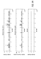
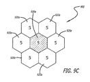
- FIGS. 9A - 9F show data for a simulation study of an exemplary case using carrier shaping of FIG. 4 , in accordance with at least one embodiment of the present disclosure.
- FIG. 9C shows the exemplary RAN antenna pattern 900 used for the simulation study.
- the RAN antenna pattern 900 is shown to comprise seven cells 920a, 930a.
- cells 920a surround cell 930a and are adjacent to cell 930a.
- Cell 930a is determined to be congested, and cells 920a are determined to be underutilized.
- a normal distribution of five (5) carriers was assigned to each cell 920a, 930a in the RAN antenna pattern 900.
- each carrier had 20 subscribers.
- FIG. 9F shows the distribution of carriers for each of the cells 920b, 930b post carrier shaping (i.e. cells 920b each have one (1) carrier and cell 930b has twenty-nine (29) carriers).
- FIG. 9A shows the graphs containing the simulation data for the uncongested cell 930a prior to carrier shaping
- FIG. 9B shows graphs containing the simulation data for a congested cell 920a prior to carrier shaping
- FIG. 9D shows graphs containing the simulation data for the uncongested cell 920b post carrier shaping
- FIG. 9E shows graphs containing the simulation data for the congested cell 930b post carrier shaping.
- the simulation study results show that post carrier shaping, call blocking decreased from 42.6% to 3.68%, the aggregate number of sessions increased from 112 to 335, and the aggregate utilization increased from 16% to 47.89%.
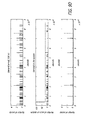
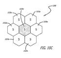
- FIGS. 10A - 10F show data for a simulation study of an exemplary case using cell shaping of FIG. 5 , in accordance with at least one embodiment of the present disclosure.
- FIG. 10C shows the exemplary RAN antenna pattern 1000 used for the simulation study.
- the RAN antenna pattern 1000 is shown to comprise seven cells 1020a, 1030a.
- cells 1020a surround cell 1030a and are adjacent to cell 1030a.
- Cell 1030a is determined to be congested, and cells 1020a are determined to be underutilized.
- a normal distribution of five (5) carriers was assigned to each cell 1020a, 1030a in the RAN antenna pattern 1000. In addition, each carrier had 20 subscribers.
- cells 1020a are enlarged to cover the area of cell 1030a by redefining the vertices of cells 1020a.
- FIG. 10F shows that cells 1020b cover the area of cell 1030b.
- FIG. 10A shows the graphs containing the simulation data for the uncongested cell 1030a prior to cell shaping
- FIG. 10B shows graphs containing the simulation data for a congested cell 1020a prior to cell shaping
- FIG. 10D shows graphs containing the simulation data for the uncongested cell 1020b post cell shaping
- FIG. 10E shows graphs containing the simulation data for the congested cell 1030b post cell shaping.
- the simulation study results show that post cell shaping, call blocking decreased from 42.6% to 1.38%, the aggregate number of sessions increased from 112 to 349, and the aggregate utilization increased from 16% to 49.86%.
- FIG. 11 is a table 1100 showing a summary of the improvement in cell congestion for the simulation study of the exemplary case using carrier shaping of FIGS. 9A - 9F and the improvement in cell congestion for the simulation study of the exemplary case using cell shaping of FIGS. 10A - 10F , in accordance with at least one embodiment of the present disclosure.
- the table 1100 shows that the baseline call blocking percentage of 42.60% decreased to 3.68% when carrier shaping was implemented and to 1.38% when cell shaping was implemented.
- the table 1100 also shows that the baseline throughput of total sessions of 112 increased to 335 sessions when carrier shaping was implemented and to 349 sessions when cell shaping was implemented.
- the table 1100 shows that the baseline total utilization capacity of 16.00% increased to 47.89% when carrier shaping was implemented and to 49.86% when cell shaping was implemented.
- the disclosed system and method for self-optimizing MSS resources may employ one or more than one of the disclosed four techniques (i.e. (1) carrier shaping, (2) cell shaping, (3) cell type selection, and (4) beam shaping) in order to relieve congestion of a congested cell.
- the disclosed system and method may employ the techniques of carrier shaping and cell shaping in conjunction together to relieve congestion of a congested cell.
- the disclosed system and method may employ the techniques of cell shaping and beam shaping in conjunction together to relieve congestion of a congested cell.
- FIG. 12 illustrates a block diagram of an illustrative computing system 1200 suitable for implementing an embodiment of the present disclosure, in accordance with at least one embodiment of the present disclosure.
- at least one processor which may be located within at least one satellite, at least one BSS, and/or at least one NOC
- the disclosed system for self-optimizing MSS resources may include and/or employ at least a portion of the disclosed computer system 1200.
- Computing system 1200 includes a bus 1206 or other communication mechanism for communicating information, which interconnects subsystems and devices, such as processor 1207, system memory 1208 (e.g., RAM), static storage device 1209 (e.g., ROM), disk drive 1210 (e.g., magnetic or optical), communication interface 1214 (e.g., modem or Ethernet card), display 1211 (e.g., CRT or LCD), input device 1212 (e.g., keyboard), and cursor control (not shown).
- processor 1207 system memory 1208 (e.g., RAM), static storage device 1209 (e.g., ROM), disk drive 1210 (e.g., magnetic or optical), communication interface 1214 (e.g., modem or Ethernet card), display 1211 (e.g., CRT or LCD), input device 1212 (e.g., keyboard), and cursor control (not shown).
- system memory 1208 e.g., RAM
- static storage device 1209 e.g., ROM
- disk drive 1210
- computer system 1200 performs specific operations by processor 1207 executing one or more sequences of one or more instructions contained in system memory 1208. Such instructions may be read into system memory 1208 from another computer readable/usable medium, such as static storage device 1209 or disk drive 1210.
- hard-wired circuitry may be used in place of or in combination with software instructions to implement the present disclosure.
- embodiments of the present disclosure are not limited to any specific combination of hardware circuitry and/or software.
- the term "logic" shall mean any combination of software or hardware that is used to implement all or part of the present disclosure.
- Nonvolatile media includes, for example, optical or magnetic disks, such as disk drive 1210.
- Volatile media includes dynamic memory, such as system memory 1208.
- Computer readable media includes, for example, floppy disk, flexible disk, hard disk, magnetic tape, any other magnetic medium, CD-ROM, any other optical medium, punch cards, paper tape, any other physical medium with patterns of holes, RAM, PROM, EPROM, FLASH-EPROM, any other memory chip or cartridge, or any other medium from which a computer can read.
- execution of the sequences of instructions to practice the present disclosure is performed by a single computer system 1200.
- two or more computer systems 1200 coupled by communication link 1215 may perform the sequence of instructions required to practice the present disclosure in coordination with one another.
- Computer system 1200 may transmit and receive messages, data, and instructions, including program, i.e., application code, through communication link 1215 and communication interface 1214. Received program code may be executed by processor 1207 as it is received, and/or stored in disk drive 1210, or other nonvolatile storage for later execution. Computer system 1200 may also interact with a database 1232 within a database system 1231 via a data interface 1233 where the computer system 1200 may store and retrieve information or data of the electronic design into and from the database system 1231.
- program i.e., application code
Landscapes
- Engineering & Computer Science (AREA)
- Computer Networks & Wireless Communication (AREA)
- Signal Processing (AREA)
- Physics & Mathematics (AREA)
- Astronomy & Astrophysics (AREA)
- Aviation & Aerospace Engineering (AREA)
- General Physics & Mathematics (AREA)
- Mobile Radio Communication Systems (AREA)
- Radio Relay Systems (AREA)
Abstract
Description
- The present disclosure relates to Mobile Satellite Systems (MSS). In particular, it relates to self-optimizing cellular MSS networks.
- Currently, when cells in a MSS experience traffic congestion, an open loop approach to allocation of Radio Access Network (RAN) resources is used to respond. This open loop approach implies that manual intervention by a system operator is required in order to respond to the transient periods of congestion in the network. Manual intervention by system operators is labor intensive and time consuming and, as such, the system operators are unable to quickly respond to these transient periods of traffic congestion in the network.
- As such, there is a need for an improved method for self-optimizing MSS resources.
- The present disclosure relates to a method, system, and apparatus for self-optimizing MSS networks. In one or more embodiments, a method for self-optimizing MSS resources involves determining, with at least one processor, the communication demand for at least one cell in a MSS network. The method further involves determining, with at least one processor, whether the communication demand for at least one cell exceeds the capacity threshold for at least one cell. Further, the method involves reallocating, with at least one processor, when the communication demand for at least one cell exceeds the capacity threshold for at least one cell, at least a portion of the MSS resources such that at least one cell is able to meet the communication demand.
- In one or more embodiments, the reallocating of at least a portion of the MSS resources comprises allocating at least one communication resource (e.g., at least one transmission frequency carrier, at least one receive frequency carrier) from at least one adjacent cell to at least one cell.
- In at least one embodiment, the reallocating of at least a portion of the MSS resources comprises redefining a shape of at least one adjacent cell to at least one cell. In some embodiments, the redefining of the shape of at least one adjacent cell comprises redefining at least one vertex of at least one adjacent cell.
- In one or more embodiments, the reallocating of at least a portion of the MSS resources comprises redefining a cell type of at least one cell. In some embodiments, the cell type is one of a standard spot cell, a micro cell, or a regional cell. In one or more embodiments, the cell type comprises cells of the same size and/or cells of different sizes.
- In at least one embodiment, the reallocating of at least a portion of the MSS resources comprises allocating greater effective isotropic radiation power (EIRP) to at least one cell. In some embodiments, the reallocating of at least a portion of the MSS resources comprises allocating greater gain over temperature (G/T) to at least one cell.
- In one or more embodiments, the capacity threshold for at least one cell is related to available frequency bandwidth of at least one cell. In some embodiments, the capacity threshold for at least one cell is predetermined. In one or more embodiments, the capacity threshold for at least one cell can be changed dynamically over time.
- In at least one embodiment, at least one cell may be a regular shape (e.g., a square, a polygon, a circle, a triangle, etc.) or an irregular shape (i.e. a shape having sides of different lengths and/or angles of different sizes). In some embodiments, the reallocating of at least a portion of the MSS resources occurs without a handover event.
- In at least one embodiment, a system for self-optimizing MSS resources involves at least one processor to determine the communication demand for at least one cell in a MSS network; to determine whether the communication demand for at least one cell exceeds the capacity threshold for at least one cell; and to reallocate, when the communication demand for at least one cell exceeds the capacity threshold for at least one cell, at least a portion of the MSS resources such that at least one cell is able to meet the communication demand.
- In one or more embodiments, when at least one processor is to reallocate at least a portion of the MSS resources, at least one processor is to allocate at least one communication resource from at least one adjacent cell to at least one cell.
- In at least one embodiment, when at least one processor is to reallocate at least a portion of the MSS resources, at least one processor is to redefine a shape of at least one adjacent cell to at least one cell. In some embodiments, when at least one processor is to redefine the shape of at least one adjacent cell, at least one processor is to redefine at least one vertex of at least one adjacent cell.
- In one or more embodiments, when at least one processor is to reallocate at least a portion of the MSS resources, at least one processor is to redefine a cell type of at least one cell. In some embodiments, the cell type is one of a standard spot cell, a micro cell, or a regional cell.
- In at least one embodiment, when at least one processor is to reallocate at least a portion of the MSS resources, at least one processor is to allocate greater effective isotropic radiation power (EIRP) to at least one cell. In some embodiments, when at least one processor is to reallocate at least a portion of the MSS resources, at least one processor is to allocate greater gain over temperature (G/T) to at least one cell.
- In one or more embodiments, the capacity threshold for at least one cell is related to available frequency bandwidth of at least one cell. In some embodiments, the capacity threshold for at least one cell is predetermined. In at least one embodiment, the capacity threshold for at least one cell can be changed dynamically over time.
- The features, functions, and advantages can be achieved independently in various embodiments of the present disclosure or may be combined in yet other embodiments.
- These and other features, aspects, and advantages of the present disclosure will become better understood with regard to the following description, appended claims, and accompanying drawings where:
-
FIG. 1 is a diagram showing an exemplary MSS network that may be employed by the disclosed system and method for self-optimizing MSS resources, in accordance with at least one embodiment of the present disclosure. -
FIG. 2 is a diagram showing an exemplary cellular network supported by a terrestrial cellular system that may be employed by the disclosed system and method for self-optimizing cellular resources, in accordance with at least one embodiment of the present disclosure. -
FIG. 3 depicts a flow chart depicting the disclosed method for self-optimizing MSS resources, in accordance with at least one embodiment of the present disclosure. -
FIG. 4 is a diagram illustrating carrier shaping that may be employed by the disclosed system and method for self-optimizing MSS resources, in accordance with at least one embodiment of the present disclosure. -
FIG. 5 is a diagram illustrating cell shaping that may be employed by the disclosed system and method for self-optimizing MSS resources, in accordance with at least one embodiment of the present disclosure. -
FIG. 6 is a diagram illustrating cell type selection that may be employed by the disclosed system and method for self-optimizing MSS resources, in accordance with at least one embodiment of the present disclosure. -
FIGS. 7A, 7B, and 7C are diagrams showing different exemplary cell types that may be used for the cell type selection ofFIG. 6 , in accordance with at least one embodiment of the present disclosure. -
FIGS. 8A and 8B are diagrams illustrating beam shaping that may be employed by the disclosed system and method for self-optimizing MSS resources, in accordance with at least one embodiment of the present disclosure. -
FIGS. 9A - 9F show data for a simulation study of an exemplary case using carrier shaping ofFIG. 4 , in accordance with at least one embodiment of the present disclosure. -
FIGS. 10A - 10F show data for a simulation study of an exemplary case using cell shaping ofFIG. 5 , in accordance with at least one embodiment of the present disclosure. -
FIG. 11 is a table showing a summary of the improvement in cell congestion for the simulation study of the exemplary case using carrier shaping ofFIGS. 9A - 9F and the improvement in cell congestion for the simulation study of the exemplary case using cell shaping ofFIGS. 10A - 10F , in accordance with at least one embodiment of the present disclosure. -
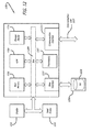
FIG. 12 illustrates a block diagram of an illustrative computing system suitable for implementing an embodiment of the present disclosure, in accordance with at least one embodiment of the present disclosure. - The methods and apparatus disclosed herein provide an operative system for self-optimizing MSS networks. The disclosed system employs automated methods to respond to transient cell congestion epochs by using techniques such as (1) carrier shaping, (2) cell shaping, (3) cell type selection, and (4) beam shaping. Based on performance parameter data of the MSS network, RAN resources are automatically, dynamically modified locally to more efficiently satisfy local surges in demand.
- Currently, network planning for MSS networks is very labor intensive with network planners developing and validating multiple resource plans; and with network operators installing, validating, and activating the static configurations associated with the resource plans. Resource plans are used to define the static configuration of MSS resources. Resource plans contain configurations for the MSS network specifying, for example, cell type; cell identification (ID); cell vertices (e.g., defined by latitude and longitude); frequency resuse of cells (e.g., denoted by colors); beamports per cell; carriers per beamport; frequencies, bandwidths, and power per carrier; terminal types (such as data terminals, handheld terminals (e.g., ruggedized terminals, smartphones, laptops, and tablets), asset tracking terminals (e.g., inconspicuous terminals), vehicular terminals, maritime terminals, and aeronautical terminals) for cells; effective isotropic radiation power (EIRP) for cells; gain over temperature (G/T) for cells; and/or data rates for cells. The labor intensive validation of the static resource plan requires additional operational cost and complexity.
- The introduction of data-intensive mobile user terminals (such as smartphones, tablets, and universal serial bus (USB) MODEM-attached laptops) yields increasingly bursty traffic loads, high variability of active user locations, and an exponential increase in mobile broadband subscribers. These factors increase the likelihood of a serving cell becoming congested, while its neighboring cells remain underutilized.
- The present disclosure presents a framework and collection of design tactics that enable the migration from the current practice of open loop radio resource planning (i.e. manual resource planning) to a closed loop method (i.e. automated dynamic resource planning) that targets detection and mitigation of MSS resource underutilization, while ensuring the overall stability of the MSS network. In addition to enabling the harvesting stranded network capacity, the closed loop system and method described herein enable a more streamlined MSS network planning and operations.
- The waveform-agnostic framework and methods described herein anticipate the future needs of mobile network operators, while providing a key design discriminator for MSS networks supported by satellite systems and/or by terrestrial MSS systems.
- In the following description, numerous details are set forth in order to provide a more thorough description of the system. It will be apparent, however, to one skilled in the art, that the disclosed system may be practiced without these specific details. In the other instances, well known features have not been described in detail so as not to unnecessarily obscure the system.
- Embodiments of the present disclosure may be described herein in terms of functional and/or logical block components and various processing steps. It should be appreciated that such block components may be realized by any number of hardware, software, and/or firmware components configured to perform the specified functions. For example, an embodiment of the present disclosure may employ various integrated circuit components, e.g., memory elements, digital signal processing elements, logic elements, look-up tables, or the like, which may carry out a variety of functions under the control of one or more microprocessors or other control devices. In addition, those skilled in the art will appreciate that embodiments of the present disclosure may be practiced in conjunction with, and that the system described herein is merely one example embodiment of the present disclosure.
- For the sake of brevity, conventional techniques and components related to MSS networks, and other functional aspects of the system (and the individual operating components of the systems) may not be described in detail herein. Furthermore, the connecting lines shown in the various figures contained herein are intended to represent example functional relationships and/or physical couplings between the various elements. It should be noted that many alternative or additional functional relationships or physical connections may be present in an embodiment of the present disclosure.
-
FIG. 1 is a diagram 100 showing an exemplary MSS network that may be employed by the disclosed system and method for self-optimizing MSS resources, in accordance with at least one embodiment of the present disclosure. In this figure, a MSS network comprising a plurality ofcells 110 is shown. Also in this figure, asatellite 130, which is part of a satellite system, is radiating theRAN antenna pattern 120 ontoEarth 140. In this example, theantenna pattern 120 is radiated over Mexico, Central America, and part of South America. However, it should be noted that in other embodiments, theantenna pattern 120 may be radiated over various different areas of theEarth 140 than is shown inFIG. 1 . - The
satellite 130 may be part of a satellite system that comprises a constellation of satellites. Thesatellite 130 may be orbiting theEarth 140, for example, in a low Earth orbit (LEO) or a medium Earth orbit (MEO). In one or more embodiments, more than onesatellite 130 may be used to radiate theRAN antenna pattern 120. -
FIG. 2 is a diagram 200 showing an exemplary cellular network supported by a terrestrial cellular system that may be employed by the disclosed system and method for self-optimizing RAN resources, in accordance with at least one embodiment of the present disclosure. In this figure, a cellular network comprising a plurality ofcells 210 is shown. In this example, the plurality ofcells 210 are situated over the continental United States. However, it should be noted that in other embodiments, the plurality ofcells 210 may be situated over various different areas of theEarth 140 than is shown inFIG. 2 . - Also in this figure, a plurality of Base Station Subsystems (BSS) 230, which are part of a terrestrial cellular system, are radiating the
cellular antenna pattern 220 ontoEarth 240. In one or more embodiments, asingle BSS 230 may be used to radiate onecell 210 or more than onecell 210 of thecellular antenna pattern 220. -
FIG. 3 depicts a flow chart depicting the disclosedmethod 300 for self-optimizing RAN resources, in accordance with at least one embodiment of the present disclosure. At thestart 310 of themethod 300, at least one processor determines a communication demand for at least one cell in aMSS network 320. In one or more embodiments, at least one processor is located within at least one satellite, at least one BSS, and/or at least one network operations center (NOC). Then, at least one processor determines whether the communication demand for at least one cell exceeds a capacity threshold for at least onecell 330. - When the communication demand for at least one cell exceeds the capacity threshold for at least one cell, at least one processor reallocates at least a portion of the MSS resources such that at least one cell is able to meet the
communication demand 340. In one or more embodiments, at least one processor reallocates at least a portion of the MSS resources by (1) allocating a carrier from at least one adjacent cell (i.e. carrier shaping), (2) redefining a shape of at least one adjacent cell (i.e. cell shaping), (3) redefining a cell type of at least one cell (i.e. cell type selection), and/or (4) allocating greater effective isotropic radiation power (EIRP) to at least one cell and/or allocating greater gain over temperature (G/T) to at least one cell (i.e. beam shaping). Then, themethod 300 ends 350. -
FIG. 4 is a diagram 400 illustrating carrier shaping that may be employed by the disclosed system and method for self-optimizing MSS resources, in accordance with at least one embodiment of the present disclosure. In this figure, a RAN antenna pattern 410 is shown to comprise sevencells 420a (i.e. N1, N2, N3, N5, N6, and N7), 430a (i.e. N4). In the RAN antenna pattern 410,cells 420asurround cell 430a and are adjacent tocell 430a. - At least one processor (which may be located within at least one satellite, at least one BSS, and/or at least one NOC) determines the communication demand (e.g., which may be related to available frequency bandwidth, data rate, and/or power) for each of the
cells cells cells cells cells - In this example, at least one processor has determined that for the
cell 430a located in the center of the RAN antenna pattern 410, its communication demand exceeds its capacity threshold and, as such, thecell 430a is identified as congested. In addition, for this example, at least one processor has determined that for thecells 420a surrounding thecongested cell 430a, their respective communication demand is lower than their capacity threshold and, as such, thecells 420a are identified as underutilized. - In order to relieve the congestion of the
cell 430a, at least one processor performs carrier shaping 440 by allocating a number of carriers fromadjacent cells 420a tocell 430a, such thatcell 430b is now able to meet its communication demand and such thatcells 420b are still able to meet their respective communication demands. As such, for this example, post carrier shaping 440,cells 420b (i.e. N1, N2, N3, N5, N6, and N7) will each have k1, k2, k3, k5, k6, and k7, respectively, number of less carriers andcell 430b (i.e. N4) will have ∑ki (where i = 1, 2, 3, 5, 6, 7) number of more carriers. It should be noted that in one or more embodiments, at least one processor may perform carrier shaping by allocating carriers from underutilized cells that are adjacent and/or are not directly adjacent to the congested cell. -
FIG. 5 is a diagram 500 illustrating cell shaping that may be employed by the disclosed system and method for self-optimizing MSS resources, in accordance with at least one embodiment of the present disclosure. In this figure, aRAN antenna pattern 510 is shown to comprise sevencells RAN antenna pattern 510,cells 520a (i.e. cells N1 - N3 and N5 - N7)surround cell 530a (i.e. cell N4) and are adjacent tocell 530a. For this example, eachcell RAN antenna pattern 510 is the same cell type and, as such, eachcell - At least one processor (which may be located within at least one satellite, at least one BSS, and/or at least one NOC) determines the communication demand (e.g., which may be related to available frequency bandwidth, data rate, and/or power) for each of the
cells RAN antenna pattern 510. Then, at least one processor determines whether the respective communication demand for each of thecells cells cells cells - In this example, at least one processor has determined that for the
cell 530a located in the center of theRAN antenna pattern 510, its communication demand exceeds its capacity threshold and, as such, thecell 530a is identified as congested. In addition, for this example, at least one processor has determined that for thecells 520a surrounding thecongested cell 530a, their respective communication demand is lower than their capacity threshold and, as such, thecells 520a are identified as underutilized. - In order to relieve the congestion of the
cell 530a, at least one processor performs cell shaping 540 by enlargingcells 520a to cover at least a portion of the area ofcell 530a by redefining the vertices ofcells 520a, such thatcell 530b is now able to meet its communication demand and such thatcells 520b are still able to meet their respective communication demands. - It should be noted that, in this example, as shown in
FIG. 5 , thecells 520a (i.e. cells N1 - N3 and N5 - N7) have all been enlarged to cover portions of the area ofcell 530a (i.e. cell N4) such that theenlarged cells 520b (i.e. cells N1 - N3 and N5-N7) symmetrically cover portions ofcell 530b (i.e. cell N4). However, it should be noted that in some embodiments for cell shaping, not all of thecells 520a (i.e. cells N1 - N3 and N5 - N7) need to be enlarged by the same amount of size (i.e. not all of thecells 520a need to have their vertices changed by the same amount of distance) such that theenlarged cells 520b cover portions of thecell 530b symmetrically. In one example, for these embodiments of cell shaping, one surrounding cell (e.g., 520a (cell N1)) may have its vertices enlarged to cover a first portion of the congested cell (e.g.,cell 530a) and another surrounding cell (e.g., 520a (cell N2)) may have its vertices enlarged to cover a second portion of the congested cell (e.g.,cell 530a), where the first portion is larger than the second portion and, as such, the coverage of the portions of the congested cell (e.g.,cell 530a) are non-symmetric. - In addition, it should be noted that, in some embodiments for cell shaping, not all of the surrounding cells (e.g.,
cells 520a) of a congested cell (e.g.,cell 530a) need to be enlarged to cover a portion of the congested cell (e.g.,cell 530a). In one example for these embodiments for cell shaping, one surrounding cell (e.g., 520a (cell N1)) may be enlarged to cover a portion of the congested cell (e.g., 530a). In another example for these embodiments of cell shaping, two surrounding cells (e.g., 520a (cells N1 and N2)) may be enlarged to cover a portion of the congested cell (e.g., 530a). -
FIG. 6 is a diagram 600 illustrating cell type selection that may be employed by the disclosed system and method for self-optimizing MSS resources, in accordance with at least one embodiment of the present disclosure. In this figure, aRAN antenna pattern 610 is shown to comprise sevencells RAN antenna pattern 610,cells 620a (i.e. cells N1 - N3 and N5 - N7)surround cell 630a (i.e. cell N4) and are adjacent tocell 630a. For this example, eachcell RAN antenna pattern 610 is the same cell type. The cell type for thecells - At least one processor (which may be located within at least one satellite, at least one BSS, and/or at least one NOC) determines the communication demand (e.g., which may be related to available frequency bandwidth, data rate, and/or power) for each of the
cells RAN antenna pattern 610. At least one processor then determines whether the respective communication demand for each of thecells cells cells cells - In this example, at least one processor has determined that for the
cell 630a located in the center of theRAN antenna pattern 610, its communication demand exceeds its capacity threshold and, as such, thecell 630a is identified as congested. - In order to relieve the congestion of the
cell 630a, at least one processor performscell type selection 640 by handing over a portion of the terminals incell 630a to an overlappingcell 650 of a larger cell type (e.g., a regional cell type), such thatcell 630b is now able to meet its communication demand. -
FIGS. 7A, 7B, and 7C are diagrams showing different exemplary cell types that may be used for the cell type selection ofFIG. 6 , in accordance with at least one embodiment of the present disclosure. In particular,FIG. 7A illustrates an exemplary cell type ofstandard spot cells 710,FIG. 7B illustrates an exemplary cell type ofmicrocells 720, andFIG. 7C illustrates an exemplary cell type ofregional cells 730. -
FIGS. 8A and 8B are diagrams illustrating beam shaping that may be employed by the disclosed system and method for self-optimizing MSS resources, in accordance with at least one embodiment of the present disclosure. In Particular,FIG. 8A depicts aBeam Weight Generator 800, andFIG. 8B shows an exemplaryRAN antenna pattern 810 comprising a plurality ofcells 820. For this example, thecells 820 are shown to have various effective isotropic radiation power (EIRP) in dBi, as shown inbeam pattern 830. Also for this example, thecells 820 employ a seven (7) colorfrequency reuse scheme 840. Each "color" represents a specific predetermined frequency band. - At least one processor (which may be located within at least one satellite, at least one BSS, and/or at least one NOC) determines the communication demand (e.g., which may be related to available frequency bandwidth, data rate, and/or power) for each of the
cells 820 in theRAN antenna pattern 810. At least one processor then determines whether the respective communication demand for each of thecells 820 exceeds the respective capacity threshold (e.g., which may be related to available frequency bandwidth, data rate, and/or power) for each of thecells 820. In one or more embodiments, the capacity threshold for each of thecells 820 is predetermined. In some embodiments, the capacity threshold for each of thecells 820 can be changed dynamically over time (e.g., changed by a system operator and/or by a network operations center). - In this example, if at least one processor has determined that a
cell 820 located within theRAN antenna pattern 810 has a communication demand that exceeds its capacity threshold, then thatcell 820 is identified as congested. In addition, if at least one processor has determined thatother cells 820 surrounding thecongested cell 820 have a respective communication demand that is lower than their respective capacity threshold, then thecells 820 are identified as underutilized. - If a cell (or beam) 820 is found to be congested and sufficient power is available in the system (i.e. at least one
cell 820 is underutilized), the Target (aggregate) carrier over interference (C/I)input 850 to the Beam Forming Network (BFN) beamweight generator function 800 can be modified to increase the spectral efficiency of thecongested beam 820. This will have the effect of increasing beam gain for users in thecongested cell 820 with a slight degradation being imposed for users at the edge of the coverage area of thecell pattern 810. Thebeam weight generator 800, with the assistance of a beamweight generator tool 880 and/or asystem engineer 890, is able to produce the newbeamweight coefficients 895 by utilizingfeed patterns 810, mainlobe gain 860, Target C/I 850, thecell pattern 870, and thefrequency reuse pan 840. - Alternately, when a cell (or beam) 820 is found to be congested, the
reuse distance 897 can be increased, for example, from a four (4) color reuse scheme to a seven (7) color reuse scheme, or from a 7 color reuse scheme to a twenty-eight (28) color reuse scheme. This has the overall effect of increasingbeam 820 gain due to a decrease in interference experienced by users at the edge of the cell orbeam coverage 810. - It should be noted that in one or more embodiments, at least one processor may perform beam shaping by allocating EIRP from underutilized cells that are adjacent and/or are not directly adjacent to the congested cell. Additionally, it should also be noted that in other embodiments, at least one processor may perform beam shaping by allocating gain over temperature (G/T) dB/W from underutilized cells that are adjacent and/or are not directly adjacent to the congested cell.
-
FIGS. 9A - 9F show data for a simulation study of an exemplary case using carrier shaping ofFIG. 4 , in accordance with at least one embodiment of the present disclosure. In particular,FIG. 9C shows the exemplaryRAN antenna pattern 900 used for the simulation study. TheRAN antenna pattern 900 is shown to comprise sevencells RAN antenna pattern 900,cells 920asurround cell 930a and are adjacent tocell 930a.Cell 930a is determined to be congested, andcells 920a are determined to be underutilized. For the simulation study, a normal distribution of five (5) carriers was assigned to eachcell RAN antenna pattern 900. In addition, each carrier had 20 subscribers. In order to relieve the congestion of thecell 930a, during carrier shaping, four (4) carriers were allocated from eachadjacent cell 920a tocell 930a. And,FIG. 9F shows the distribution of carriers for each of thecells cells 920b each have one (1) carrier andcell 930b has twenty-nine (29) carriers). - In addition,
FIG. 9A shows the graphs containing the simulation data for theuncongested cell 930a prior to carrier shaping,FIG. 9B shows graphs containing the simulation data for acongested cell 920a prior to carrier shaping,FIG. 9D shows graphs containing the simulation data for theuncongested cell 920b post carrier shaping, andFIG. 9E shows graphs containing the simulation data for thecongested cell 930b post carrier shaping. The simulation study results show that post carrier shaping, call blocking decreased from 42.6% to 3.68%, the aggregate number of sessions increased from 112 to 335, and the aggregate utilization increased from 16% to 47.89%. -
FIGS. 10A - 10F show data for a simulation study of an exemplary case using cell shaping ofFIG. 5 , in accordance with at least one embodiment of the present disclosure. In particular,FIG. 10C shows the exemplaryRAN antenna pattern 1000 used for the simulation study. TheRAN antenna pattern 1000 is shown to comprise sevencells RAN antenna pattern 1000,cells 1020asurround cell 1030a and are adjacent tocell 1030a.Cell 1030a is determined to be congested, andcells 1020a are determined to be underutilized. For the simulation study, a normal distribution of five (5) carriers was assigned to eachcell RAN antenna pattern 1000. In addition, each carrier had 20 subscribers. In order to relieve the congestion of thecell 1030a, during cell shaping,cells 1020a are enlarged to cover the area ofcell 1030a by redefining the vertices ofcells 1020a.FIG. 10F shows thatcells 1020b cover the area ofcell 1030b. - In addition,
FIG. 10A shows the graphs containing the simulation data for theuncongested cell 1030a prior to cell shaping,FIG. 10B shows graphs containing the simulation data for acongested cell 1020a prior to cell shaping,FIG. 10D shows graphs containing the simulation data for theuncongested cell 1020b post cell shaping, andFIG. 10E shows graphs containing the simulation data for thecongested cell 1030b post cell shaping. The simulation study results show that post cell shaping, call blocking decreased from 42.6% to 1.38%, the aggregate number of sessions increased from 112 to 349, and the aggregate utilization increased from 16% to 49.86%. -
FIG. 11 is a table 1100 showing a summary of the improvement in cell congestion for the simulation study of the exemplary case using carrier shaping ofFIGS. 9A - 9F and the improvement in cell congestion for the simulation study of the exemplary case using cell shaping ofFIGS. 10A - 10F , in accordance with at least one embodiment of the present disclosure. In this figure, the table 1100 shows that the baseline call blocking percentage of 42.60% decreased to 3.68% when carrier shaping was implemented and to 1.38% when cell shaping was implemented. The table 1100 also shows that the baseline throughput of total sessions of 112 increased to 335 sessions when carrier shaping was implemented and to 349 sessions when cell shaping was implemented. Also, the table 1100 shows that the baseline total utilization capacity of 16.00% increased to 47.89% when carrier shaping was implemented and to 49.86% when cell shaping was implemented. - It should be noted that, in one or more embodiments, the disclosed system and method for self-optimizing MSS resources may employ one or more than one of the disclosed four techniques (i.e. (1) carrier shaping, (2) cell shaping, (3) cell type selection, and (4) beam shaping) in order to relieve congestion of a congested cell. For an example, in some embodiments, the disclosed system and method may employ the techniques of carrier shaping and cell shaping in conjunction together to relieve congestion of a congested cell. In another example, in some embodiments, the disclosed system and method may employ the techniques of cell shaping and beam shaping in conjunction together to relieve congestion of a congested cell.
-
FIG. 12 illustrates a block diagram of anillustrative computing system 1200 suitable for implementing an embodiment of the present disclosure, in accordance with at least one embodiment of the present disclosure. For example, at least one processor (which may be located within at least one satellite, at least one BSS, and/or at least one NOC) of the disclosed system for self-optimizing MSS resources may include and/or employ at least a portion of the disclosedcomputer system 1200.Computing system 1200 includes abus 1206 or other communication mechanism for communicating information, which interconnects subsystems and devices, such asprocessor 1207, system memory 1208 (e.g., RAM), static storage device 1209 (e.g., ROM), disk drive 1210 (e.g., magnetic or optical), communication interface 1214 (e.g., modem or Ethernet card), display 1211 (e.g., CRT or LCD), input device 1212 (e.g., keyboard), and cursor control (not shown). - According to one embodiment of the present disclosure,
computer system 1200 performs specific operations byprocessor 1207 executing one or more sequences of one or more instructions contained insystem memory 1208. Such instructions may be read intosystem memory 1208 from another computer readable/usable medium, such asstatic storage device 1209 ordisk drive 1210. In alternative embodiments, hard-wired circuitry may be used in place of or in combination with software instructions to implement the present disclosure. Thus, embodiments of the present disclosure are not limited to any specific combination of hardware circuitry and/or software. In one embodiment, the term "logic" shall mean any combination of software or hardware that is used to implement all or part of the present disclosure. - The term "computer readable medium" or "computer usable medium" as used herein refers to any medium that participates in providing instructions to
processor 1207 for execution. Such a medium may take many forms, including but not limited to, non-volatile media, volatile media, and transmission media. Nonvolatile media includes, for example, optical or magnetic disks, such asdisk drive 1210. Volatile media includes dynamic memory, such assystem memory 1208. - Common forms of computer readable media includes, for example, floppy disk, flexible disk, hard disk, magnetic tape, any other magnetic medium, CD-ROM, any other optical medium, punch cards, paper tape, any other physical medium with patterns of holes, RAM, PROM, EPROM, FLASH-EPROM, any other memory chip or cartridge, or any other medium from which a computer can read.
- In an embodiment of the present disclosure, execution of the sequences of instructions to practice the present disclosure is performed by a
single computer system 1200. According to other embodiments of the present disclosure, two ormore computer systems 1200 coupled by communication link 1215 (e.g., LAN, PTSN, or wireless network) may perform the sequence of instructions required to practice the present disclosure in coordination with one another. -
Computer system 1200 may transmit and receive messages, data, and instructions, including program, i.e., application code, throughcommunication link 1215 andcommunication interface 1214. Received program code may be executed byprocessor 1207 as it is received, and/or stored indisk drive 1210, or other nonvolatile storage for later execution.Computer system 1200 may also interact with adatabase 1232 within adatabase system 1231 via adata interface 1233 where thecomputer system 1200 may store and retrieve information or data of the electronic design into and from thedatabase system 1231. - Although particular embodiments have been shown and described, it should be understood that the above discussion is not intended to limit the scope of these embodiments. While embodiments and variations of the many aspects of the present disclosure have been disclosed and described herein, such disclosure is provided for purposes of explanation and illustration only. Thus, various changes and modifications may be made without departing from the scope of the claims.
- Where methods described above indicate certain events occurring in certain order, those of ordinary skill in the art having the benefit of this disclosure would recognize that the ordering may be modified and that such modifications are in accordance with the variations of the present disclosure. Additionally, parts of methods may be performed concurrently in a parallel process when possible, as well as performed sequentially. In addition, more parts or less part of the methods may be performed.
- Accordingly, embodiments are intended to exemplify alternatives, modifications, and equivalents that may fall within the scope of the claims.
- Although certain illustrative embodiments and methods have been disclosed herein, it can be apparent from the foregoing disclosure to those skilled in the art that variations and modifications of such embodiments and methods can be made without departing from the true spirit and scope of the art disclosed. Many other examples of the art disclosed exist, each differing from others in matters of detail only. Accordingly, it is intended that the art disclosed shall be limited only to the extent required by the appended claims and the rules and principles of applicable law.
Claims (15)
- A method for self-optimizing MSS resources, the method comprising:determining, with at least one processor, a communication demand for at least one cell in a MSS network;determining, with the at least one processor, whether the communication demand for the at least one cell exceeds a capacity threshold for the at least one cell; andreallocating, with the at least one processor, when the communication demand for the at least one cell exceeds the capacity threshold for the at least one cell, at least a portion of the MSS resources such that the at least one cell is able to meet the communication demand.
- The method of claim 1, wherein the reallocating of the at least a portion of the MSS resources comprises allocating at least one communication resource from at least one adjacent cell to the at least one cell.
- The method of claim 1 or 2, wherein the reallocating of the at least a portion of the MSS resources comprises at least one of redefining a shape of at least one adjacent cell to the at least one cell.
- The method of claim 1, 2 or 3, wherein the reallocating of the at least a portion of the MSS resources comprises redefining a cell type of the at least one cell.
- The method of any of claims 1 to 4, wherein the reallocating of the at least a portion of the MSS resources comprises allocating greater effective isotropic radiation power (EIRP) to the at least one cell or allocating greater gain over temperature (G/T) to the at least one cell.
- The method of any of claims 1 to 5, wherein the capacity threshold for the at least one cell is related to available frequency bandwidth of the at least one cell or the capacity threshold for the at least one cell is predetermined.
- The method of any of claims 1 to 6, wherein the at least one cell may be one of a regular shape and an irregular shape.
- The method of any of claims 1 to 7, wherein the reallocating of the at least a portion of the MSS resources occurs without a handover event.
- A system for self-optimizing MSS resources, the system comprising:at least one processor to determine a communication demand for at least one cell in a MSS network; to determine whether the communication demand for the at least one cell exceeds a capacity threshold for the at least one cell; andto reallocate, when the communication demand for the at least one cell exceeds the capacity threshold for the at least one cell, at least a portion of the MSS resources such that the at least one cell is able to meet the communication demand.
- The system of claim 9, wherein when the at least one processor is to reallocate the at least a portion of the MSS resources, the at least one processor is to allocate at least one communication resource from at least one adjacent cell to the at least one cell.
- The system of claim 9 or 10, wherein when the at least one processor is to reallocate the at least a portion of the MSS resources, the at least one processor is to redefine a shape of at least one adjacent cell to the at least one cell.
- The system of claim 9, 10 or 11, wherein when the at least one processor is to redefine the shape of the at least one adjacent cell, the at least one processor is to redefine at least one vertex of the at least one adjacent cell.
- The system of any of claims 9 to 12, wherein when the at least one processor is to reallocate the at least a portion of the MSS resources, the at least one processor is to redefine a cell type of the at least one cell.
- The system of any of claims 9 to 13, wherein the cell type is one of a standard spot cell, a micro cell, or a regional cell.
- The system of any of claims 9 to 14, wherein when the at least one processor is to reallocate the at least a portion of the MSS resources, the at least one processor is to allocate greater effective isotropic radiation power (EIRP) to the at least one cell.
Applications Claiming Priority (1)
| Application Number | Priority Date | Filing Date | Title |
|---|---|---|---|
| US14/502,802 US9942892B2 (en) | 2014-09-30 | 2014-09-30 | Self-optimizing mobile satellite systems |
Publications (2)
| Publication Number | Publication Date |
|---|---|
| EP3002890A1 true EP3002890A1 (en) | 2016-04-06 |
| EP3002890B1 EP3002890B1 (en) | 2020-09-16 |
Family
ID=54292573
Family Applications (1)
| Application Number | Title | Priority Date | Filing Date |
|---|---|---|---|
| EP15187550.7A Active EP3002890B1 (en) | 2014-09-30 | 2015-09-30 | Method and system for self-optimizing a resource for a mobile service by satellite. |
Country Status (3)
| Country | Link |
|---|---|
| US (1) | US9942892B2 (en) |
| EP (1) | EP3002890B1 (en) |
| RU (1) | RU2690162C2 (en) |
Cited By (1)
| Publication number | Priority date | Publication date | Assignee | Title |
|---|---|---|---|---|
| EP3863193A1 (en) * | 2020-02-10 | 2021-08-11 | The Boeing Company | Adaptive self-optimizing network using closed-loop feedback |
Families Citing this family (11)
| Publication number | Priority date | Publication date | Assignee | Title |
|---|---|---|---|---|
| CN106095529B (en) * | 2016-06-08 | 2019-07-02 | 西安电子科技大学 | A carrier migration method under C-RAN architecture |
| US10142967B2 (en) * | 2017-03-10 | 2018-11-27 | Mediatek Inc. | Method of handling radio resource |
| US10276581B1 (en) | 2017-10-31 | 2019-04-30 | Taiwan Semiconductor Manufacturing Co., Ltd. | Integrated circuit chip and manufacturing method thereof |
| US11962393B2 (en) * | 2018-03-08 | 2024-04-16 | Smiths Interconnect, Inc. | Network agnostic dynamic SATCOM system and associated network features |
| US11050616B2 (en) | 2018-12-20 | 2021-06-29 | The Boeing Company | Adaptive self-optimizing network using closed-loop feedback |
| US10771989B2 (en) | 2018-12-20 | 2020-09-08 | The Boeing Company | Adaptive self-optimizing network using closed-loop feedback |
| CN115765829A (en) * | 2019-06-28 | 2023-03-07 | 华为技术有限公司 | Method and device for cell selection in NTN |
| EP3783811A1 (en) * | 2019-08-19 | 2021-02-24 | Vodafone IP Licensing Limited | Configuration of high altitude platform-based cellular radio access network |
| US12035145B2 (en) * | 2021-12-09 | 2024-07-09 | Dish Wireless L.L.C. | Automated sector creation in physical radiofrequency network deployments |
| CN115272091A (en) * | 2022-03-18 | 2022-11-01 | 广州极飞科技股份有限公司 | Image processing method, device, equipment and storage medium |
| US12476702B1 (en) * | 2025-07-10 | 2025-11-18 | Telcom Ventures, Llc | Methods and devices to generate a spectrum utilization map for devices in spot beams served by a mobile satellite service network |
Citations (4)
| Publication number | Priority date | Publication date | Assignee | Title |
|---|---|---|---|---|
| WO2001041548A2 (en) * | 1999-12-10 | 2001-06-14 | Motorola, Inc. | Variable beam size digital beamforming system |
| US20100309828A1 (en) * | 2009-06-09 | 2010-12-09 | Atc Technologies, Llc | Systems, methods and network components that provide different satellite spot beam return carrier groupings and reuse patterns |
| US20130009809A1 (en) * | 2011-07-08 | 2013-01-10 | Thales | Multi-Spot Satellite System with Efficient Space Resource Allocation |
| US20130244570A1 (en) * | 2012-03-13 | 2013-09-19 | Electronics And Telecommunications Research Institute | Apparatus and method for allocating resource in multi-beam satellite communication |
Family Cites Families (27)
| Publication number | Priority date | Publication date | Assignee | Title |
|---|---|---|---|---|
| US5448621A (en) * | 1993-08-02 | 1995-09-05 | Motorola, Inc. | Dynamic reallocation of spectral capacity in cellular communication systems |
| US5574968A (en) * | 1994-06-01 | 1996-11-12 | Motorola, Inc. | Satellite cellular communication methods for performing cell-to-cell handoff |
| US5732353A (en) * | 1995-04-07 | 1998-03-24 | Ericsson Inc. | Automatic control channel planning in adaptive channel allocation systems |
| US5898681A (en) * | 1996-09-30 | 1999-04-27 | Amse Subsidiary Corporation | Methods of load balancing and controlling congestion in a combined frequency division and time division multiple access communication system using intelligent login procedures and mobile terminal move commands |
| US6574474B1 (en) * | 1999-05-20 | 2003-06-03 | Avaya Technology Corp. | Load balancing for cellular and wireless systems |
| DE60033350T2 (en) * | 1999-10-15 | 2007-07-12 | Northrop Grumman Corp., Los Angeles | Dynamic selection of beamwidth for multiple access cells with uneven distribution |
| US8121605B2 (en) * | 2002-06-27 | 2012-02-21 | Globalstar, Inc. | Resource allocation to terrestrial and satellite services |
| US20060068848A1 (en) * | 2003-01-28 | 2006-03-30 | Celletra Ltd. | System and method for load distribution between base station sectors |
| EP2128686B1 (en) * | 2008-05-29 | 2017-07-05 | LG Electronics Inc. | Mobile terminal with a solar cell module integrated under the display and method for controlling the display |
| KR20100070279A (en) * | 2008-12-17 | 2010-06-25 | 이용석 | Method for operating femto-cell in wireless communication system |
| US8855677B2 (en) * | 2011-01-12 | 2014-10-07 | Telefonaktiebolaget Lm Ericsson (Publ) | Nodes and methods for positioning |
| JP5379177B2 (en) * | 2011-02-10 | 2013-12-25 | 株式会社日立製作所 | Distributed antenna system, base station apparatus, and radio resource control method |
| US9191851B2 (en) * | 2011-09-29 | 2015-11-17 | Telefonaktiebolaget L M Ericsson (Publ) | Cell size and shape estimation in heterogeneous networks |
| US8712438B1 (en) * | 2012-05-24 | 2014-04-29 | Sprint Spectrum L.P. | Method and system for associating a cell-sector with time-dependent location parameters |
| JP2014017587A (en) * | 2012-07-06 | 2014-01-30 | Fujitsu Ltd | Radio communication network area design method, computer program, and radio communication network area design device |
| US8995255B2 (en) * | 2012-08-03 | 2015-03-31 | Intel Corporation | Coverage adjustment in E-UTRA networks |
| US9648502B2 (en) * | 2012-08-15 | 2017-05-09 | Trimble Navigation Limited | System for tailoring wireless coverage to a geographic area |
| WO2014043665A2 (en) * | 2012-09-17 | 2014-03-20 | Interdigital Patent Holdings, Inc. | Self-optimization of backhaul radio reseources and small cell backhaul delay estimation |
| GB2506150A (en) * | 2012-09-21 | 2014-03-26 | Nec Corp | Scheduling of Machine Type Communications (MTC) in a wireless communications system |
| CN104854773B (en) * | 2013-01-14 | 2018-05-11 | 英特尔Ip公司 | Energy acquisition equipment in wireless network |
| US9414399B2 (en) * | 2013-02-07 | 2016-08-09 | Commscope Technologies Llc | Radio access networks |
| WO2015009211A1 (en) * | 2013-07-18 | 2015-01-22 | Telefonaktiebolaget L M Ericsson (Publ) | Methods and devices for cell reconfiguration |
| US9107041B2 (en) * | 2013-08-07 | 2015-08-11 | Alcatel Lucent | Systems and methods for determining a user equipment location based on measurements from multiple base stations |
| EP2869622B1 (en) * | 2013-11-05 | 2016-08-03 | Telefonica Digital España, S.L.U. | Method and device for locating network activity in cellular communication networks |
| US9374161B2 (en) * | 2013-11-21 | 2016-06-21 | Comtech Ef Data Corp. | System and method for satellite link budget analysis (LBA) optimization |
| US9426666B2 (en) * | 2013-11-26 | 2016-08-23 | The Boeing Company | Integrated resource planning for satellite systems |
| EP3186995A1 (en) * | 2014-08-28 | 2017-07-05 | Telefonaktiebolaget LM Ericsson (publ) | Methods receiving radiation pattern information and related network nodes and base stations |
-
2014
- 2014-09-30 US US14/502,802 patent/US9942892B2/en active Active
-
2015
- 2015-07-03 RU RU2015126662A patent/RU2690162C2/en active
- 2015-09-30 EP EP15187550.7A patent/EP3002890B1/en active Active
Patent Citations (4)
| Publication number | Priority date | Publication date | Assignee | Title |
|---|---|---|---|---|
| WO2001041548A2 (en) * | 1999-12-10 | 2001-06-14 | Motorola, Inc. | Variable beam size digital beamforming system |
| US20100309828A1 (en) * | 2009-06-09 | 2010-12-09 | Atc Technologies, Llc | Systems, methods and network components that provide different satellite spot beam return carrier groupings and reuse patterns |
| US20130009809A1 (en) * | 2011-07-08 | 2013-01-10 | Thales | Multi-Spot Satellite System with Efficient Space Resource Allocation |
| US20130244570A1 (en) * | 2012-03-13 | 2013-09-19 | Electronics And Telecommunications Research Institute | Apparatus and method for allocating resource in multi-beam satellite communication |
Cited By (1)
| Publication number | Priority date | Publication date | Assignee | Title |
|---|---|---|---|---|
| EP3863193A1 (en) * | 2020-02-10 | 2021-08-11 | The Boeing Company | Adaptive self-optimizing network using closed-loop feedback |
Also Published As
| Publication number | Publication date |
|---|---|
| US9942892B2 (en) | 2018-04-10 |
| US20160095109A1 (en) | 2016-03-31 |
| EP3002890B1 (en) | 2020-09-16 |
| RU2015126662A (en) | 2017-01-12 |
| RU2690162C2 (en) | 2019-05-31 |
| RU2015126662A3 (en) | 2018-12-20 |
Similar Documents
| Publication | Publication Date | Title |
|---|---|---|
| EP3002890B1 (en) | Method and system for self-optimizing a resource for a mobile service by satellite. | |
| US9288844B1 (en) | Wireless radio access point configuration | |
| EP3632150B1 (en) | Method and apparatus for dynamic protection area (dpa) protection | |
| US11470014B2 (en) | System and method of managing data connections to a communication network using tiered devices and telemetry data | |
| EP3220682B1 (en) | Radio resource management system and radio resource management method | |
| JP7670679B2 (en) | Multiple simultaneous bandwidth segments for a base station of a cellular network | |
| JPH04302547A (en) | Channel assignment method and system in cellular radio telephone system | |
| Smith et al. | An O-RAN approach to spectrum sharing between commercial 5G and government satellite systems | |
| US20130095822A1 (en) | Dynamic radio capabilities based upon available transport bandwidth | |
| JP6632908B2 (en) | Method and device for reallocating resources in satellite-terrestrial integrated network and computer program | |
| KR102333864B1 (en) | Uav arrangement device and method based on machine learning for maximizing communication throughput | |
| EP3748996B1 (en) | Radio resource management system and radio resource management method | |
| JP7633992B2 (en) | Multi-tenant wireless network management based on traffic monitoring | |
| EP4084521A1 (en) | Communication control device and communication control method | |
| TWI633804B (en) | Communication control device, communication control method, and information processing device | |
| JP7620613B2 (en) | Bandwidth adjustment of multiple simultaneous bandwidth portions for a base station of a cellular network - Patents.com | |
| CN114885336B (en) | Interference coordination method, device and storage medium | |
| KR20140124108A (en) | Apparatus and method of dynamic spectrum allocation based on spectrum auction using binary integer programming | |
| US20230318684A1 (en) | Apparatus, methods and computer programs | |
| EP3804381B1 (en) | Cellular telecommunications network | |
| CN103650560A (en) | Co-cell frequency planning method and equipment | |
| US12328594B2 (en) | Method and apparatus for determining base stations to be deployed based on interference values to stationary communication stations | |
| US12192783B2 (en) | Station placement designing assistance apparatus, station placement designing assistance method and program | |
| CN109155916B (en) | Electronic device and method for electronic device | |
| CN119946600B (en) | Deployment method, equipment, communication system and storage medium of emergency communication network |
Legal Events
| Date | Code | Title | Description |
|---|---|---|---|
| PUAI | Public reference made under article 153(3) epc to a published international application that has entered the european phase |
Free format text: ORIGINAL CODE: 0009012 |
|
| 17P | Request for examination filed |
Effective date: 20150930 |
|
| AK | Designated contracting states |
Kind code of ref document: A1 Designated state(s): AL AT BE BG CH CY CZ DE DK EE ES FI FR GB GR HR HU IE IS IT LI LT LU LV MC MK MT NL NO PL PT RO RS SE SI SK SM TR |
|
| AX | Request for extension of the european patent |
Extension state: BA ME |
|
| 17Q | First examination report despatched |
Effective date: 20161018 |
|
| RBV | Designated contracting states (corrected) |
Designated state(s): AL AT BE BG CH CY CZ DE DK EE ES FI FR GB GR HR HU IE IS IT LI LT LU LV MC MK MT NL NO PL PT RO RS SE SI SK SM TR |
|
| STAA | Information on the status of an ep patent application or granted ep patent |
Free format text: STATUS: EXAMINATION IS IN PROGRESS |
|
| GRAP | Despatch of communication of intention to grant a patent |
Free format text: ORIGINAL CODE: EPIDOSNIGR1 |
|
| STAA | Information on the status of an ep patent application or granted ep patent |
Free format text: STATUS: GRANT OF PATENT IS INTENDED |
|
| INTG | Intention to grant announced |
Effective date: 20200325 |
|
| GRAS | Grant fee paid |
Free format text: ORIGINAL CODE: EPIDOSNIGR3 |
|
| GRAA | (expected) grant |
Free format text: ORIGINAL CODE: 0009210 |
|
| STAA | Information on the status of an ep patent application or granted ep patent |
Free format text: STATUS: THE PATENT HAS BEEN GRANTED |
|
| AK | Designated contracting states |
Kind code of ref document: B1 Designated state(s): AL AT BE BG CH CY CZ DE DK EE ES FI FR GB GR HR HU IE IS IT LI LT LU LV MC MK MT NL NO PL PT RO RS SE SI SK SM TR |
|
| REG | Reference to a national code |
Ref country code: GB Ref legal event code: FG4D |
|
| REG | Reference to a national code |
Ref country code: CH Ref legal event code: EP |
|
| REG | Reference to a national code |
Ref country code: DE Ref legal event code: R096 Ref document number: 602015059092 Country of ref document: DE |
|
| REG | Reference to a national code |
Ref country code: IE Ref legal event code: FG4D |
|
| REG | Reference to a national code |
Ref country code: AT Ref legal event code: REF Ref document number: 1315099 Country of ref document: AT Kind code of ref document: T Effective date: 20201015 |
|
| PG25 | Lapsed in a contracting state [announced via postgrant information from national office to epo] |
Ref country code: HR Free format text: LAPSE BECAUSE OF FAILURE TO SUBMIT A TRANSLATION OF THE DESCRIPTION OR TO PAY THE FEE WITHIN THE PRESCRIBED TIME-LIMIT Effective date: 20200916 Ref country code: FI Free format text: LAPSE BECAUSE OF FAILURE TO SUBMIT A TRANSLATION OF THE DESCRIPTION OR TO PAY THE FEE WITHIN THE PRESCRIBED TIME-LIMIT Effective date: 20200916 Ref country code: NO Free format text: LAPSE BECAUSE OF FAILURE TO SUBMIT A TRANSLATION OF THE DESCRIPTION OR TO PAY THE FEE WITHIN THE PRESCRIBED TIME-LIMIT Effective date: 20201216 Ref country code: BG Free format text: LAPSE BECAUSE OF FAILURE TO SUBMIT A TRANSLATION OF THE DESCRIPTION OR TO PAY THE FEE WITHIN THE PRESCRIBED TIME-LIMIT Effective date: 20201216 Ref country code: SE Free format text: LAPSE BECAUSE OF FAILURE TO SUBMIT A TRANSLATION OF THE DESCRIPTION OR TO PAY THE FEE WITHIN THE PRESCRIBED TIME-LIMIT Effective date: 20200916 Ref country code: GR Free format text: LAPSE BECAUSE OF FAILURE TO SUBMIT A TRANSLATION OF THE DESCRIPTION OR TO PAY THE FEE WITHIN THE PRESCRIBED TIME-LIMIT Effective date: 20201217 |
|
| REG | Reference to a national code |
Ref country code: AT Ref legal event code: MK05 Ref document number: 1315099 Country of ref document: AT Kind code of ref document: T Effective date: 20200916 |
|
| REG | Reference to a national code |
Ref country code: NL Ref legal event code: MP Effective date: 20200916 |
|
| PG25 | Lapsed in a contracting state [announced via postgrant information from national office to epo] |
Ref country code: LV Free format text: LAPSE BECAUSE OF FAILURE TO SUBMIT A TRANSLATION OF THE DESCRIPTION OR TO PAY THE FEE WITHIN THE PRESCRIBED TIME-LIMIT Effective date: 20200916 Ref country code: RS Free format text: LAPSE BECAUSE OF FAILURE TO SUBMIT A TRANSLATION OF THE DESCRIPTION OR TO PAY THE FEE WITHIN THE PRESCRIBED TIME-LIMIT Effective date: 20200916 |
|
| REG | Reference to a national code |
Ref country code: LT Ref legal event code: MG4D |
|
| PG25 | Lapsed in a contracting state [announced via postgrant information from national office to epo] |
Ref country code: CZ Free format text: LAPSE BECAUSE OF FAILURE TO SUBMIT A TRANSLATION OF THE DESCRIPTION OR TO PAY THE FEE WITHIN THE PRESCRIBED TIME-LIMIT Effective date: 20200916 Ref country code: EE Free format text: LAPSE BECAUSE OF FAILURE TO SUBMIT A TRANSLATION OF THE DESCRIPTION OR TO PAY THE FEE WITHIN THE PRESCRIBED TIME-LIMIT Effective date: 20200916 Ref country code: SM Free format text: LAPSE BECAUSE OF FAILURE TO SUBMIT A TRANSLATION OF THE DESCRIPTION OR TO PAY THE FEE WITHIN THE PRESCRIBED TIME-LIMIT Effective date: 20200916 Ref country code: RO Free format text: LAPSE BECAUSE OF FAILURE TO SUBMIT A TRANSLATION OF THE DESCRIPTION OR TO PAY THE FEE WITHIN THE PRESCRIBED TIME-LIMIT Effective date: 20200916 Ref country code: NL Free format text: LAPSE BECAUSE OF FAILURE TO SUBMIT A TRANSLATION OF THE DESCRIPTION OR TO PAY THE FEE WITHIN THE PRESCRIBED TIME-LIMIT Effective date: 20200916 Ref country code: PT Free format text: LAPSE BECAUSE OF FAILURE TO SUBMIT A TRANSLATION OF THE DESCRIPTION OR TO PAY THE FEE WITHIN THE PRESCRIBED TIME-LIMIT Effective date: 20210118 Ref country code: LT Free format text: LAPSE BECAUSE OF FAILURE TO SUBMIT A TRANSLATION OF THE DESCRIPTION OR TO PAY THE FEE WITHIN THE PRESCRIBED TIME-LIMIT Effective date: 20200916 |
|
| REG | Reference to a national code |
Ref country code: CH Ref legal event code: PL |
|
| PG25 | Lapsed in a contracting state [announced via postgrant information from national office to epo] |
Ref country code: IS Free format text: LAPSE BECAUSE OF FAILURE TO SUBMIT A TRANSLATION OF THE DESCRIPTION OR TO PAY THE FEE WITHIN THE PRESCRIBED TIME-LIMIT Effective date: 20210116 Ref country code: PL Free format text: LAPSE BECAUSE OF FAILURE TO SUBMIT A TRANSLATION OF THE DESCRIPTION OR TO PAY THE FEE WITHIN THE PRESCRIBED TIME-LIMIT Effective date: 20200916 Ref country code: AL Free format text: LAPSE BECAUSE OF FAILURE TO SUBMIT A TRANSLATION OF THE DESCRIPTION OR TO PAY THE FEE WITHIN THE PRESCRIBED TIME-LIMIT Effective date: 20200916 Ref country code: AT Free format text: LAPSE BECAUSE OF FAILURE TO SUBMIT A TRANSLATION OF THE DESCRIPTION OR TO PAY THE FEE WITHIN THE PRESCRIBED TIME-LIMIT Effective date: 20200916 Ref country code: ES Free format text: LAPSE BECAUSE OF FAILURE TO SUBMIT A TRANSLATION OF THE DESCRIPTION OR TO PAY THE FEE WITHIN THE PRESCRIBED TIME-LIMIT Effective date: 20200916 |
|
| REG | Reference to a national code |
Ref country code: DE Ref legal event code: R097 Ref document number: 602015059092 Country of ref document: DE |
|
| REG | Reference to a national code |
Ref country code: BE Ref legal event code: MM Effective date: 20200930 |
|
| PG25 | Lapsed in a contracting state [announced via postgrant information from national office to epo] |
Ref country code: MC Free format text: LAPSE BECAUSE OF FAILURE TO SUBMIT A TRANSLATION OF THE DESCRIPTION OR TO PAY THE FEE WITHIN THE PRESCRIBED TIME-LIMIT Effective date: 20200916 Ref country code: SK Free format text: LAPSE BECAUSE OF FAILURE TO SUBMIT A TRANSLATION OF THE DESCRIPTION OR TO PAY THE FEE WITHIN THE PRESCRIBED TIME-LIMIT Effective date: 20200916 Ref country code: LU Free format text: LAPSE BECAUSE OF NON-PAYMENT OF DUE FEES Effective date: 20200930 |
|
| PLBE | No opposition filed within time limit |
Free format text: ORIGINAL CODE: 0009261 |
|
| STAA | Information on the status of an ep patent application or granted ep patent |
Free format text: STATUS: NO OPPOSITION FILED WITHIN TIME LIMIT |
|
| 26N | No opposition filed |
Effective date: 20210617 |
|
| PG25 | Lapsed in a contracting state [announced via postgrant information from national office to epo] |
Ref country code: BE Free format text: LAPSE BECAUSE OF NON-PAYMENT OF DUE FEES Effective date: 20200930 Ref country code: DK Free format text: LAPSE BECAUSE OF FAILURE TO SUBMIT A TRANSLATION OF THE DESCRIPTION OR TO PAY THE FEE WITHIN THE PRESCRIBED TIME-LIMIT Effective date: 20200916 Ref country code: CH Free format text: LAPSE BECAUSE OF NON-PAYMENT OF DUE FEES Effective date: 20200930 Ref country code: SI Free format text: LAPSE BECAUSE OF FAILURE TO SUBMIT A TRANSLATION OF THE DESCRIPTION OR TO PAY THE FEE WITHIN THE PRESCRIBED TIME-LIMIT Effective date: 20200916 Ref country code: LI Free format text: LAPSE BECAUSE OF NON-PAYMENT OF DUE FEES Effective date: 20200930 Ref country code: IE Free format text: LAPSE BECAUSE OF NON-PAYMENT OF DUE FEES Effective date: 20200930 |
|
| PG25 | Lapsed in a contracting state [announced via postgrant information from national office to epo] |
Ref country code: IT Free format text: LAPSE BECAUSE OF FAILURE TO SUBMIT A TRANSLATION OF THE DESCRIPTION OR TO PAY THE FEE WITHIN THE PRESCRIBED TIME-LIMIT Effective date: 20200916 |
|
| PG25 | Lapsed in a contracting state [announced via postgrant information from national office to epo] |
Ref country code: TR Free format text: LAPSE BECAUSE OF FAILURE TO SUBMIT A TRANSLATION OF THE DESCRIPTION OR TO PAY THE FEE WITHIN THE PRESCRIBED TIME-LIMIT Effective date: 20200916 Ref country code: MT Free format text: LAPSE BECAUSE OF FAILURE TO SUBMIT A TRANSLATION OF THE DESCRIPTION OR TO PAY THE FEE WITHIN THE PRESCRIBED TIME-LIMIT Effective date: 20200916 Ref country code: CY Free format text: LAPSE BECAUSE OF FAILURE TO SUBMIT A TRANSLATION OF THE DESCRIPTION OR TO PAY THE FEE WITHIN THE PRESCRIBED TIME-LIMIT Effective date: 20200916 |
|
| PG25 | Lapsed in a contracting state [announced via postgrant information from national office to epo] |
Ref country code: MK Free format text: LAPSE BECAUSE OF FAILURE TO SUBMIT A TRANSLATION OF THE DESCRIPTION OR TO PAY THE FEE WITHIN THE PRESCRIBED TIME-LIMIT Effective date: 20200916 |
|
| P01 | Opt-out of the competence of the unified patent court (upc) registered |
Effective date: 20230516 |
|
| PGFP | Annual fee paid to national office [announced via postgrant information from national office to epo] |
Ref country code: DE Payment date: 20250929 Year of fee payment: 11 |
|
| PGFP | Annual fee paid to national office [announced via postgrant information from national office to epo] |
Ref country code: GB Payment date: 20250929 Year of fee payment: 11 |
|
| PGFP | Annual fee paid to national office [announced via postgrant information from national office to epo] |
Ref country code: FR Payment date: 20250925 Year of fee payment: 11 |