EP3002846A1 - Method, controller, and computer program product for controlling a voltage in a power grid - Google Patents
Method, controller, and computer program product for controlling a voltage in a power grid Download PDFInfo
- Publication number
- EP3002846A1 EP3002846A1 EP14187096.4A EP14187096A EP3002846A1 EP 3002846 A1 EP3002846 A1 EP 3002846A1 EP 14187096 A EP14187096 A EP 14187096A EP 3002846 A1 EP3002846 A1 EP 3002846A1
- Authority
- EP
- European Patent Office
- Prior art keywords
- bus
- voltage
- power
- robust optimization
- tolerance range
- Prior art date
- Legal status (The legal status is an assumption and is not a legal conclusion. Google has not performed a legal analysis and makes no representation as to the accuracy of the status listed.)
- Granted
Links
Images
Classifications
-
- H—ELECTRICITY
- H02—GENERATION; CONVERSION OR DISTRIBUTION OF ELECTRIC POWER
- H02J—ELECTRIC POWER NETWORKS; CIRCUIT ARRANGEMENTS OR SYSTEMS FOR SUPPLYING OR DISTRIBUTING ELECTRIC POWER; SYSTEMS FOR STORING ELECTRIC ENERGY
- H02J3/00—Circuit arrangements for AC mains or AC distribution networks
- H02J3/38—Arrangements for feeding a single network from two or more generators or sources in parallel; Arrangements for feeding already energised networks from additional generators or sources in parallel
- H02J3/46—Controlling the sharing of generated power between the generators, sources or networks
-
- G—PHYSICS
- G05—CONTROLLING; REGULATING
- G05B—CONTROL OR REGULATING SYSTEMS IN GENERAL; FUNCTIONAL ELEMENTS OF SUCH SYSTEMS; MONITORING OR TESTING ARRANGEMENTS FOR SUCH SYSTEMS OR ELEMENTS
- G05B15/00—Systems controlled by a computer
- G05B15/02—Systems controlled by a computer electric
-
- H—ELECTRICITY
- H02—GENERATION; CONVERSION OR DISTRIBUTION OF ELECTRIC POWER
- H02J—ELECTRIC POWER NETWORKS; CIRCUIT ARRANGEMENTS OR SYSTEMS FOR SUPPLYING OR DISTRIBUTING ELECTRIC POWER; SYSTEMS FOR STORING ELECTRIC ENERGY
- H02J3/00—Circuit arrangements for AC mains or AC distribution networks
- H02J3/04—Arrangements for connecting networks of the same frequency but supplied from different sources
- H02J3/06—Controlling the transfer of power between connected networks; Controlling load sharing between connected networks
-
- H—ELECTRICITY
- H02—GENERATION; CONVERSION OR DISTRIBUTION OF ELECTRIC POWER
- H02J—ELECTRIC POWER NETWORKS; CIRCUIT ARRANGEMENTS OR SYSTEMS FOR SUPPLYING OR DISTRIBUTING ELECTRIC POWER; SYSTEMS FOR STORING ELECTRIC ENERGY
- H02J2101/00—Supply or distribution of decentralised, dispersed or local electric power generation
- H02J2101/20—Dispersed power generation using renewable energy sources
-
- H—ELECTRICITY
- H02—GENERATION; CONVERSION OR DISTRIBUTION OF ELECTRIC POWER
- H02J—ELECTRIC POWER NETWORKS; CIRCUIT ARRANGEMENTS OR SYSTEMS FOR SUPPLYING OR DISTRIBUTING ELECTRIC POWER; SYSTEMS FOR STORING ELECTRIC ENERGY
- H02J2103/00—Details of circuit arrangements for mains or AC distribution networks
- H02J2103/30—Simulating, planning, modelling, reliability check or computer assisted design [CAD] of electric power networks
-
- H—ELECTRICITY
- H02—GENERATION; CONVERSION OR DISTRIBUTION OF ELECTRIC POWER
- H02J—ELECTRIC POWER NETWORKS; CIRCUIT ARRANGEMENTS OR SYSTEMS FOR SUPPLYING OR DISTRIBUTING ELECTRIC POWER; SYSTEMS FOR STORING ELECTRIC ENERGY
- H02J3/00—Circuit arrangements for AC mains or AC distribution networks
- H02J3/38—Arrangements for feeding a single network from two or more generators or sources in parallel; Arrangements for feeding already energised networks from additional generators or sources in parallel
- H02J3/381—Dispersed generators
-
- H—ELECTRICITY
- H02—GENERATION; CONVERSION OR DISTRIBUTION OF ELECTRIC POWER
- H02J—ELECTRIC POWER NETWORKS; CIRCUIT ARRANGEMENTS OR SYSTEMS FOR SUPPLYING OR DISTRIBUTING ELECTRIC POWER; SYSTEMS FOR STORING ELECTRIC ENERGY
- H02J3/00—Circuit arrangements for AC mains or AC distribution networks
- H02J3/38—Arrangements for feeding a single network from two or more generators or sources in parallel; Arrangements for feeding already energised networks from additional generators or sources in parallel
- H02J3/46—Controlling the sharing of generated power between the generators, sources or networks
- H02J3/48—Controlling the sharing of active power
-
- H—ELECTRICITY
- H02—GENERATION; CONVERSION OR DISTRIBUTION OF ELECTRIC POWER
- H02J—ELECTRIC POWER NETWORKS; CIRCUIT ARRANGEMENTS OR SYSTEMS FOR SUPPLYING OR DISTRIBUTING ELECTRIC POWER; SYSTEMS FOR STORING ELECTRIC ENERGY
- H02J3/00—Circuit arrangements for AC mains or AC distribution networks
- H02J3/38—Arrangements for feeding a single network from two or more generators or sources in parallel; Arrangements for feeding already energised networks from additional generators or sources in parallel
- H02J3/46—Controlling the sharing of generated power between the generators, sources or networks
- H02J3/50—Controlling the sharing of reactive power
-
- Y—GENERAL TAGGING OF NEW TECHNOLOGICAL DEVELOPMENTS; GENERAL TAGGING OF CROSS-SECTIONAL TECHNOLOGIES SPANNING OVER SEVERAL SECTIONS OF THE IPC; TECHNICAL SUBJECTS COVERED BY FORMER USPC CROSS-REFERENCE ART COLLECTIONS [XRACs] AND DIGESTS
- Y02—TECHNOLOGIES OR APPLICATIONS FOR MITIGATION OR ADAPTATION AGAINST CLIMATE CHANGE
- Y02E—REDUCTION OF GREENHOUSE GAS [GHG] EMISSIONS, RELATED TO ENERGY GENERATION, TRANSMISSION OR DISTRIBUTION
- Y02E10/00—Energy generation through renewable energy sources
- Y02E10/50—Photovoltaic [PV] energy
- Y02E10/56—Power conversion systems, e.g. maximum power point trackers
-
- Y—GENERAL TAGGING OF NEW TECHNOLOGICAL DEVELOPMENTS; GENERAL TAGGING OF CROSS-SECTIONAL TECHNOLOGIES SPANNING OVER SEVERAL SECTIONS OF THE IPC; TECHNICAL SUBJECTS COVERED BY FORMER USPC CROSS-REFERENCE ART COLLECTIONS [XRACs] AND DIGESTS
- Y02—TECHNOLOGIES OR APPLICATIONS FOR MITIGATION OR ADAPTATION AGAINST CLIMATE CHANGE
- Y02E—REDUCTION OF GREENHOUSE GAS [GHG] EMISSIONS, RELATED TO ENERGY GENERATION, TRANSMISSION OR DISTRIBUTION
- Y02E60/00—Enabling technologies; Technologies with a potential or indirect contribution to GHG emissions mitigation
-
- Y—GENERAL TAGGING OF NEW TECHNOLOGICAL DEVELOPMENTS; GENERAL TAGGING OF CROSS-SECTIONAL TECHNOLOGIES SPANNING OVER SEVERAL SECTIONS OF THE IPC; TECHNICAL SUBJECTS COVERED BY FORMER USPC CROSS-REFERENCE ART COLLECTIONS [XRACs] AND DIGESTS
- Y04—INFORMATION OR COMMUNICATION TECHNOLOGIES HAVING AN IMPACT ON OTHER TECHNOLOGY AREAS
- Y04S—SYSTEMS INTEGRATING TECHNOLOGIES RELATED TO POWER NETWORK OPERATION, COMMUNICATION OR INFORMATION TECHNOLOGIES FOR IMPROVING THE ELECTRICAL POWER GENERATION, TRANSMISSION, DISTRIBUTION, MANAGEMENT OR USAGE, i.e. SMART GRIDS
- Y04S40/00—Systems for electrical power generation, transmission, distribution or end-user application management characterised by the use of communication or information technologies, or communication or information technology specific aspects supporting them
- Y04S40/20—Information technology specific aspects, e.g. CAD, simulation, modelling, system security
Definitions
- a voltage control has to fulfill several requirements.
- the voltage of PQ buses i.e. buses where the voltage cannot be controlled directly
- Examples for PQ buses are load buses or buses with renewable power supply.
- the voltage of PV buses i.e. buses where the voltage level can be controlled directly
- Examples for PV buses are generator buses with conventional generators or buses with on-load tap changer (OLTC) transformers, reactive power compensators, flexible AC transmission systems (FACTS), or DC power grid terminals.
- Known methods for voltage control in a power grid include methods based on numerically solving a set of nonlinear power flow equations, which combine values for active powers, reactive powers, voltage amplitudes and phase angles of the PV buses and the PQ buses of the power grid. It is known to solve these power flow equations for the voltage amplitudes at the PQ buses by inputting the values for the active and reactive power supply and demand at the PQ buses and the active power supply and demand and voltage amplitude at the PV buses. These input values are measured or estimated, e.g. based on predetermined load profiles. According to known methods the optimal voltage levels at the PV buses are not determined directly but rather by an iterative solution of the power flow equations for different voltage levels. This often implies time consuming calculations. Furthermore, the dependence on estimated or varying values for the active and reactive power supply and demand leads to a significant increase of numerical complexity.
- a method, a controller, and a computer program product for controlling a voltage in a power grid comprising a PV bus and a PQ bus are provided.
- the controller and/or the computer program product may be central instances for the power grid or distributed over several communicating instances.
- a first tolerance range for an active power of the PV bus and a second tolerance range for an active power of the PQ bus are received.
- the tolerance ranges may be represented as intervals defined by minimum and maximum values of the respective quantities.
- a first value for a reactive power of the PQ bus is received.
- Robust optimization methods are a particular class of optimization methods allowing for uncertain parameters. They specifically allow the optimization of first quantities satisfying given constraints for a whole domain of uncertain second quantities.
- the constraints are often denoted as robust optimization constraints and the domain of uncertain second quantities is often denoted as uncertainty or robust optimization uncertainty.
- the first and second tolerance range and the first reactive power value are input to the robust optimization process using the first and second tolerance range as robust optimization uncertainty.
- the robust optimization process determines a voltage set point for the PV bus so that the set of power flow equations is fulfilled for the first and second tolerance range. According to the determined voltage set point a voltage at the PV bus is controlled.
- the voltage set point can be determined in compliance with the tolerance ranges even if a power supply and/or consumption is not known precisely or shows fast variations.
- the invention allows a fast and flexible determination and optimization of the voltage set point, thus allowing an efficient voltage control of the PV bus with a short reaction time.
- a third tolerance range for a voltage of the PQ bus may be received and input to the robust optimization process as a robust optimization constraint.
- the voltage set point may be determined so that the robust optimization constraint is satisfied for the first and second tolerance range.
- a nominal value for a voltage of the PQ bus may be received and input to the robust optimization process taking a difference between the nominal value and an actual voltage of the PQ bus into account in a robust optimization cost function.
- the voltage set point may be determined so that the robust optimization cost function is minimized for the first and second tolerance range.
- a deviation of the voltage set point from a nominal voltage of the PV bus may be minimized by the robust optimization process. This allows minimizing fluctuations of the voltage at the PV bus, thus enhancing voltage stability.
- the first tolerance range may be received from a conventional power generator or a high voltage direct current (HVDC) terminal at the PV bus.
- the second tolerance range and the first reactive power value may be received from a renewable power generator or a load device at the PQ bus.
- the voltage set point may be transmitted to a conventional power generator, a high voltage direct current terminal, and/or a flexible AC transmission system, e.g. a static VAR compensator, at the PV bus.
- a conventional power generator e.g. a high voltage direct current terminal
- a flexible AC transmission system e.g. a static VAR compensator
- the set of power flow equations may comprise a linearized power flow equation.
- the linearization of the linearized power flow equation may be based on neglecting a resistance of a power line of the transmission grid compared to an inductivity of the power line. Furthermore, a phase angle difference between neighboring buses may be linearized.
- the linearization of the linearized power flow equation may be based on neglecting a deviation of a voltage value from a nominal voltage of the PV bus or PQ bus compared to a voltage difference between neighboring buses. Moreover, a phase angle difference between neighboring buses may be linearized.
- the robust optimization process may be a linear robust optimization process based on a linear programming routine.
- Linear programming routines allow a particular fast and stable numerical solution of constrained optimization problems.
- the robust optimization process can be efficiently distributed over several processors.
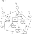
- FIG. 1 a depicts an exemplary embodiment of a power grid with several PV buses PV1, PV2 and several PQ buses PQ1, PQ2, and PQ3 in schematic representation.
- the PV buses PV1 and PV2 are generator buses with conventional power generators G.
- One of the PV buses PV1 or PV2 may be treated as a slack bus for computation purposes.
- the PQ buses PQ1 and PQ2 are load buses with load devices L while the PQ bus PQ3 is a bus with a renewable power supply W, e.g. a wind generator.
- the PV buses PV1 and PV2 and the PQ buses PQ1,...,PQ3 are connected by power lines PL.
- a controller CTL is provided in the power grid.
- the controller CTL is coupled to the PV buses PV1 and PV2 as well as to the PQ buses PQ1,...,PQ3 as indicated by dashed lines in figure 1 .
- the controller CTL receives a minimum value P min and a maximum value P max for the active power supplied or consumed by the respective power generator or load device of the respective bus. Furthermore, the controller CTL receives from each of the buses PV1, PV2, PQ1,...,PQ3 a minimum value v min and a maximum value v max for a voltage of the respective bus.
- the minimum and maximum values v min and v max may alternatively provided by a grid code of the power system.
- the values P min and P max specify a tolerance range for the active power of that bus and the values v min and v max specify a tolerance range for the voltage of that bus.
- the controller CTL receives from each of the PQ buses PQ1,...,PQ3 a value Q for the reactive power of the respective PQ bus.
- This reactive power value Q may also be a vector, in particular a pair of parameters denoting a range, in particular a tolerance range for the reactive power of the respective PQ bus. The latter may be the case when controlling the voltage of PV buses in distribution grids according to the second embodiment described below.
- the controller CTL inputs the received tolerance ranges specified by the P min , P max , v min , and v max for each bus and the received reactive power values Q for the PQ buses into a robust optimization process for a set of power flow equations as described in detail below.
- the robust optimization process outputs a respective optimized voltage set point v st for each of the PV buses PV1 and PV2 so that the robust optimization constraints are satisfied.
- Each of the respective voltage set points v st is transmitted to the respective power generator G of the respective PV bus PV1 or PV2 in order to control their voltages.
- the imaginary unit is denoted by "j”.
- ⁇ i and ⁇ k denote the phases of the voltages v i and v k at the buses B i and B k , respectively.
- the r ik , x ik , b ik , v i , v k , ⁇ i , and ⁇ k are considered real, while the z ik , v i , v k , and c ik are considered complex quantities.
- the buses B i and B k are often denoted by their index i or k, respectively.
- the power flow equations are a set of nonlinear equations combining characteristic quantities of the power grid.
- the sum includes all neighboring buses k connected to bus i by a power line.
- S i , P i , and Q i denote the net apparent power, active power and reactive power, respectively, generated at bus i.
- a power grid contains a number of generator buses, all of which are PV buses except for one which is the slack bus.
- all load buses are PQ buses.
- the power flow equations are usually solved to provide a solution on Q, ⁇ for the PV buses with P * , v* given and v, ⁇ for the PQ buses with P*, Q* given.
- Q, ⁇ , P*, v * , v, ⁇ , P*, Q* denote the vectors of the corresponding indexed quantities.
- the intervals [P *n min , P *n max ] denote tolerance ranges or uncertainties for the active powers P *n of the PV and PQ buses.
- the above question defines a so called robust optimization problem.
- Robust optimization problems are a particular known class of optimization problems allowing for uncertain parameters. They specifically allow the optimization of first quantities, here the voltages v *i of the PV buses, satisfying given constraints, here the voltages v k of the PQ buses, for a whole domain of uncertain second quantities, here the active power loads P *n of PV and PQ buses.
- the constraints are often denoted as robust optimization constraints and the domain of uncertain second quantities is often denoted as uncertainty or robust optimization uncertainty.
- the power grid comprises a transmission grid.
- the power grid comprises a distribution grid.
- the power lines may not be assumed to be purely inductive in distribution grids. With the latter, the ratio r ik /x ik may even be close to 1 or above 1.
- B ⁇ is invertible which can be shown, e.g. using Gershgorin's disc theorem.
- the above procedure related to distribution grids according to the second embodiment may be summarized in the following exemplary linear programming problem that minimizes the largest voltage offset v G - v N *1 from the nominal voltages v N of all PV buses. min ⁇ G ⁇ ⁇ G - ⁇ N 1 ⁇ ⁇ s . t .
- ⁇ X ⁇ 12 and ⁇ X ⁇ 22 specifies the lower left N L *N G and lower right N L *N L block of the matrix X and ⁇ X ⁇ 2 denotes the lower N L *N block of the matrix X.
- the invention allows for a direct optimization of the controllable voltage levels, an incorporation of uncertain active and reactive power supply and demand, and a formulation as a linear programming problem.
- the latter allows for a fast solution even for a great number of optimization variables.
Landscapes
- Engineering & Computer Science (AREA)
- Power Engineering (AREA)
- General Engineering & Computer Science (AREA)
- Physics & Mathematics (AREA)
- General Physics & Mathematics (AREA)
- Automation & Control Theory (AREA)
- Supply And Distribution Of Alternating Current (AREA)
Abstract
Description
- In contemporary power grids for transmission and/or distribution of electrical power it becomes increasingly complex to control the voltage of the various buses of the power grid. This is at least partially due to the increase of renewable power supply, which leads to faster power flow variations and reverse power flow from distribution grids to transmission grids.
- Usually, a voltage control has to fulfill several requirements. First, the voltage of PQ buses, i.e. buses where the voltage cannot be controlled directly, should be within predetermined voltage limits. Examples for PQ buses are load buses or buses with renewable power supply. Second, the voltage of PV buses, i.e. buses where the voltage level can be controlled directly, should be close to a nominal voltage value. Examples for PV buses are generator buses with conventional generators or buses with on-load tap changer (OLTC) transformers, reactive power compensators, flexible AC transmission systems (FACTS), or DC power grid terminals. These requirements should be fulfilled even in case of fast power variations of e.g. a renewable power supply. Hence, the voltage control should allow for a fast re-optimization after significant power flow variations, even for large power grids.
- Known methods for voltage control in a power grid include methods based on numerically solving a set of nonlinear power flow equations, which combine values for active powers, reactive powers, voltage amplitudes and phase angles of the PV buses and the PQ buses of the power grid. It is known to solve these power flow equations for the voltage amplitudes at the PQ buses by inputting the values for the active and reactive power supply and demand at the PQ buses and the active power supply and demand and voltage amplitude at the PV buses. These input values are measured or estimated, e.g. based on predetermined load profiles. According to known methods the optimal voltage levels at the PV buses are not determined directly but rather by an iterative solution of the power flow equations for different voltage levels. This often implies time consuming calculations. Furthermore, the dependence on estimated or varying values for the active and reactive power supply and demand leads to a significant increase of numerical complexity.
- It is an object of the present invention to provide a method, a controller, and a computer program product for controlling a voltage in a power grid that are more flexible in particular in cases of varying or uncertain power flows.
- This object is achieved by a method according to patent claim 1, a controller according to patent claim 11, and a computer program product according to patent claim 12.
- According to the invention, a method, a controller, and a computer program product for controlling a voltage in a power grid comprising a PV bus and a PQ bus are provided. The controller and/or the computer program product may be central instances for the power grid or distributed over several communicating instances. A first tolerance range for an active power of the PV bus and a second tolerance range for an active power of the PQ bus are received. Here, the tolerance ranges may be represented as intervals defined by minimum and maximum values of the respective quantities. Furthermore, a first value for a reactive power of the PQ bus is received. With that, a robust optimization process is run by a processor for a set of power flow equations combining values for active powers, reactive powers, and voltages of the PV bus and the PQ bus.
- Robust optimization methods are a particular class of optimization methods allowing for uncertain parameters. They specifically allow the optimization of first quantities satisfying given constraints for a whole domain of uncertain second quantities. The constraints are often denoted as robust optimization constraints and the domain of uncertain second quantities is often denoted as uncertainty or robust optimization uncertainty.
- According to the invention the first and second tolerance range and the first reactive power value are input to the robust optimization process using the first and second tolerance range as robust optimization uncertainty. With that, the robust optimization process determines a voltage set point for the PV bus so that the set of power flow equations is fulfilled for the first and second tolerance range. According to the determined voltage set point a voltage at the PV bus is controlled.
- Because the invention uses tolerance ranges for a robust optimization process instead of given or estimated power grid parameters, the voltage set point can be determined in compliance with the tolerance ranges even if a power supply and/or consumption is not known precisely or shows fast variations. In particular, the invention allows a fast and flexible determination and optimization of the voltage set point, thus allowing an efficient voltage control of the PV bus with a short reaction time.
- Particular embodiments of the invention are given by the dependent claims.
- According to an advantageous embodiment of the invention, a third tolerance range for a voltage of the PQ bus may be received and input to the robust optimization process as a robust optimization constraint. With that, the voltage set point may be determined so that the robust optimization constraint is satisfied for the first and second tolerance range.
- According to a further embodiment a nominal value for a voltage of the PQ bus may be received and input to the robust optimization process taking a difference between the nominal value and an actual voltage of the PQ bus into account in a robust optimization cost function. With that, the voltage set point may be determined so that the robust optimization cost function is minimized for the first and second tolerance range.
- According to an advantageous embodiment of the invention a deviation of the voltage set point from a nominal voltage of the PV bus may be minimized by the robust optimization process. This allows minimizing fluctuations of the voltage at the PV bus, thus enhancing voltage stability.
- According to an embodiment of the invention the first tolerance range may be received from a conventional power generator or a high voltage direct current (HVDC) terminal at the PV bus. Furthermore, the second tolerance range and the first reactive power value may be received from a renewable power generator or a load device at the PQ bus.
- Moreover, the voltage set point may be transmitted to a conventional power generator, a high voltage direct current terminal, and/or a flexible AC transmission system, e.g. a static VAR compensator, at the PV bus.
- Advantageously, the set of power flow equations may comprise a linearized power flow equation.
- For a transmission grid the linearization of the linearized power flow equation may be based on neglecting a resistance of a power line of the transmission grid compared to an inductivity of the power line. Furthermore, a phase angle difference between neighboring buses may be linearized.
- For a distribution grid the linearization of the linearized power flow equation may be based on neglecting a deviation of a voltage value from a nominal voltage of the PV bus or PQ bus compared to a voltage difference between neighboring buses. Moreover, a phase angle difference between neighboring buses may be linearized.
- With the above linearizations the power flow equations can be simplified considerably. This allows a fast and stable numerical solution even in case of a very large power grid.
- Moreover, the robust optimization process may be a linear robust optimization process based on a linear programming routine. Linear programming routines allow a particular fast and stable numerical solution of constrained optimization problems. Furthermore, the robust optimization process can be efficiently distributed over several processors.
- Particular embodiments of the invention are described in the following paragraphs in conjunction with the drawings.
- The drawings show in schematic representation:
- Figure 1
- a power grid with several PV buses and several PQ buses, and
- Figure 2
- a branch model representing a connection between two buses.
-
Figure 1 a depicts an exemplary embodiment of a power grid with several PV buses PV1, PV2 and several PQ buses PQ1, PQ2, and PQ3 in schematic representation. According to that embodiment, the PV buses PV1 and PV2 are generator buses with conventional power generators G. One of the PV buses PV1 or PV2 may be treated as a slack bus for computation purposes. Furthermore, the PQ buses PQ1 and PQ2 are load buses with load devices L while the PQ bus PQ3 is a bus with a renewable power supply W, e.g. a wind generator. The PV buses PV1 and PV2 and the PQ buses PQ1,...,PQ3 are connected by power lines PL. - For controlling voltages of the conventional power generators G of the PV buses PV1 and PV2 a controller CTL is provided in the power grid. The controller CTL is coupled to the PV buses PV1 and PV2 as well as to the PQ buses PQ1,...,PQ3 as indicated by dashed lines in
figure 1 . - From each of the buses PV1, PV2, PQ1,...,PQ3, the controller CTL receives a minimum value Pmin and a maximum value Pmax for the active power supplied or consumed by the respective power generator or load device of the respective bus. Furthermore, the controller CTL receives from each of the buses PV1, PV2, PQ1,...,PQ3 a minimum value vmin and a maximum value vmax for a voltage of the respective bus. The minimum and maximum values vmin and vmax may alternatively provided by a grid code of the power system. For each bus, the values Pmin and Pmax specify a tolerance range for the active power of that bus and the values vmin and vmax specify a tolerance range for the voltage of that bus.
- Moreover, the controller CTL receives from each of the PQ buses PQ1,...,PQ3 a value Q for the reactive power of the respective PQ bus. This reactive power value Q may also be a vector, in particular a pair of parameters denoting a range, in particular a tolerance range for the reactive power of the respective PQ bus. The latter may be the case when controlling the voltage of PV buses in distribution grids according to the second embodiment described below.
- The controller CTL inputs the received tolerance ranges specified by the Pmin, Pmax, vmin, and vmax for each bus and the received reactive power values Q for the PQ buses into a robust optimization process for a set of power flow equations as described in detail below. The robust optimization process outputs a respective optimized voltage set point vst for each of the PV buses PV1 and PV2 so that the robust optimization constraints are satisfied. Each of the respective voltage set points vst is transmitted to the respective power generator G of the respective PV bus PV1 or PV2 in order to control their voltages.
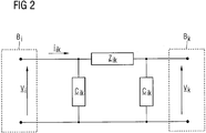
- A common network model of a power grid represents a power line between two power grid buses Bi and Bk by a complex series impedance z ik = rik + j*xik and complex shunt admittance c ik = j*bik, the latter being equally split between adjacent buses. Here and in the following the imaginary unit is denoted by "j".
Figure 2 shows a schematic representation of a line or branch model with complex node voltages v i = vi*exp(j*θi) at bus Bi and v k = vk*exp(j*θk) at bus Bk and complex current i ik = (v i-v k)/z ik flowing from bus Bi to adjacent bus Bk. - Here, θi and θk denote the phases of the voltages v i and v k at the buses Bi and Bk, respectively. The rik, xik, bik, vi, vk, θi, and θk are considered real, while the z ik, v i, v k, and c ik are considered complex quantities. In the following, the buses Bi and Bk are often denoted by their index i or k, respectively.
- The apparent power Sik flowing from bus i bus to bus k is given by:

- This leads to the known AC, i.e. alternating current, power flow equations for a power grid with N buses:


- The power flow equations are a set of nonlinear equations combining characteristic quantities of the power grid. Here, the sum includes all neighboring buses k connected to bus i by a power line. Si, Pi, and Qi denote the net apparent power, active power and reactive power, respectively, generated at bus i.
- There are three types of buses
- slack bus s: with vs = 1 and θs = 0, provides the missing active power and reactive power in order to balance the power flow equations (s denotes the index of the slack bus),
- PV bus i: with Pi = P*i and vi = v*i for given P*i, v*i, (typically a generator bus), and
- PQ bus k: with Pk = P*k and Qk = Q*k for given P*k, Q*k, (typically a load bus).
- Usually, a power grid contains a number of generator buses, all of which are PV buses except for one which is the slack bus. Typically, all load buses are PQ buses.
- According to prior art, the power flow equations are usually solved to provide a solution on Q, θ for the PV buses with P*, v* given and v, θ for the PQ buses with P*, Q* given. Here, Q, θ, P*, v*, v, θ, P*, Q* denote the vectors of the corresponding indexed quantities.
- With the present invention, in contrast, the following question is considered:
- Given a power grid with one slack bus, NG-1 PV buses, and NL PQ buses with uncertain active power loads or generators P*n with P*n min <= P*n <= P*n max, how should the voltages v*i at the PV buses be tuned such that the voltages vk at the PQ buses satisfy vk min <= vk <= vk max?
- The intervals [P*n min, P*n max] denote tolerance ranges or uncertainties for the active powers P*n of the PV and PQ buses. The above question defines a so called robust optimization problem. Robust optimization problems are a particular known class of optimization problems allowing for uncertain parameters. They specifically allow the optimization of first quantities, here the voltages v*i of the PV buses, satisfying given constraints, here the voltages vk of the PQ buses, for a whole domain of uncertain second quantities, here the active power loads P*n of PV and PQ buses. The constraints are often denoted as robust optimization constraints and the domain of uncertain second quantities is often denoted as uncertainty or robust optimization uncertainty.
- According to a first exemplary embodiment of the invention the power grid comprises a transmission grid. In transmission grids, the power lines are mainly inductive, i.e. xik >> rik. Therefore, the power flow equations (2b) can be simplified to


- For the PV buses as well as for the PQ buses, the active power is given by P*. Since the power lines are purely inductive, there is no active power loss in the transmission grid and, therefore, the active power supply of the slack node can be obtained from 1TP = 0. If P* is defined as an NG+NL-1 dimensional vector, i.e. as a vector with one dimension less than P, with one element for each PV and PQ bus, then we have


- In order to determine estimates of the voltages at the PQ buses, a result from the paper "A DC power flow extension" by T. Kyriakidis, R. Cherkaoui, and M. Kaya, in "4th IEEE PES Innovative Smart Grid Technologies (ISGT) Europe", 2013 may be used. That so called P-inv approximation is based on the DC power flow (5) assuming mainly inductive power lines to estimate the voltage phase angles. Then, the voltage levels at all buses are estimated based on an approximated AC power flow considering both inductive and resistive parameters of the power lines. This condition states


- A further linearization can be used around typical values for θi that leads to more accurate results of the phase angles θi. The phase angles θi may be different from zero but the variation of the θi depending on P* may be assumed to be small. Thus, we rewrite (8) using (7) and (6) in the following form

- Coming back to the question above, we replace v* of the PV buses by vb+Δv, where vb is the reference or base voltage and Δv is an offset to be tuned. Thus, we obtain
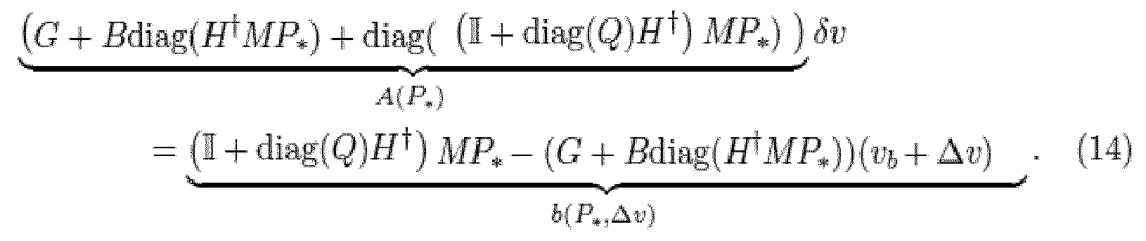
- This equality constraint contains the known parameters G, B, H, M, and vb. We are interested in the δv of the PQ buses. For these lines in (14), the elements of Q only depend on the PQ buses. Thus, also the relevant elements of Q are known. The uncertain vector P* enters linearly in the equation and the uncertainty is constrained by a convex polytope. Therefore, all admissible vectors P* can be investigated by analyzing a finite set of corner points of the convex polytope. Furthermore, the control variables Δv and the constraint output variables δv enter linearly in the constraint. Therefore, the above relation leads to a linear programming problem that can be solved easily using standard solution algorithms like interior-point methods or the known simplex algorithm.
- The above steps may be summarized in the following exemplary linear programming problem that minimizes the largest voltage offset Δv of all PV buses.



- According to a second exemplary embodiment of the invention the power grid comprises a distribution grid. In contrast to transmission grids according to the first embodiment, the power lines may not be assumed to be purely inductive in distribution grids. With the latter, the ratio rik/xik may even be close to 1 or above 1.
- For distribution grids, we also start from the AC power flow equations (2). We describe the rik/xik ratio by the phase of the complex impedance z ik = rik + j*xik = zik*exp (j*Φik),
where Φik=tan (xik/rik). It follows that
rik/(rik 2+xik 2)=cos(Φik)/zik and xik/(rik 2+xik 2)=sin (Φik)/zik. - With that we obtain

- In order to find an appropriate solution of (16), the following simplifications are advantageous:
- The phase differences are rather small, i.e. it can be assumed that sin (θi-θk) ≈ θi-θk and cos (θi-θk) ≈ 1,
- The variation of the voltages vi is negligible compared to the voltage differences between adjacent buses, i.e. vi-vk dominates the variation of the individual vi. This allows to replace some voltages by a nominal voltage vN, i.e. it can be assumed that vi≈vN,
- The shunt capacitors of the power lines may be neglected, i.e. bik≈0. Because of this assumption, the reactive power for the shunt capacitors can be added to Qi as additional constant reactive power load.
- With the above simplifications a linearized power flow equations can be derived

- The active power part of this linearized power flow equation falls back to the DC power flow equation for purely inductive powerlines, i.e. Φik=π/2. However, these equations are also valid for distribution grids. Note that the above simplifications have turned the power grid into a loss-less power grid model because the active and reactive power flowing into each power line is equal to the power flow that leaves this power line at the other end.
- Equation (16) may be rewritten in matrix form


- Similarly, B is a matrix with elements -bik = -xik/(rik 2+xik 2) = -sin(Φik)/zik on the off-diagonal and

- B and G are symmetric matrices and satisfy 1TB=B*1=0 and 1TG=G*1=0. Hence, B and G are not invertible, but 1TP=0 and 1TQ=0 is fulfilled. This shows again that the above power grid model is loss-less.
- Coming back to the question above, we consider a power grid with one slack bus, NG-1 PV buses, and NL PQ buses. Without loss of generality, it may be assumed that the first bus (i=1) is the slack bus, i.e. θ1=0 and P1 = -∑N i=2 Pi, the buses 2 to NG are PV buses, and buses NG+1 to N=NG+NL are PQ buses. With this assumption, the first row and the first column of (18) may be removed in order to obtain


- The above procedure related to distribution grids according to the second embodiment may be summarized in the following exemplary linear programming problem that minimizes the largest voltage offset vG - vN*1 from the nominal voltages vN of all PV buses.


- The embodiments as described above illustrate the advantages of the invention. In particular, the invention allows for a direct optimization of the controllable voltage levels, an incorporation of uncertain active and reactive power supply and demand, and a formulation as a linear programming problem. The latter allows for a fast solution even for a great number of optimization variables.
Claims (12)
- Method for controlling a voltage in a power grid comprising a PV bus (PV1, PV2) and a PQ bus (PQ1,...,PQ3), the method comprising:a) receiving a first tolerance range for an active power of the PV bus (PV1, PV2) and a second tolerance range for an active power of the PQ bus (PQ1,...,PQ3),b) receiving a first value for a reactive power (Q) of the PQ bus (PQ1,...,PQ3),c) running, by a processor, a robust optimization process for a set of power flow equations combining values for active powers, reactive powers, and voltages of the PV bus (PV1, PV2) and the PQ bus (PQ1,...,PQ3),d) inputting the first and second tolerance range and the first reactive power value (Q) to the robust optimization process using the first and second tolerance range as robust optimization uncertainty,e) determining by the robust optimization process a voltage set point (vst) for the PV bus (PV1, PV2) so that the set of power flow equations is fulfilled for the first and second tolerance range, andf) controlling a voltage at the PV bus (PV1, PV2) according to the determined voltage set point (vst).
- Method according to claim 1, whereina) a third tolerance range for a voltage of the PQ bus (PQ1,...,PQ3) is received,b) the third tolerance range is input to the robust optimization process as a robust optimization constraint, andc) the voltage set point (vst) is determined so that the robust optimization constraint is satisfied for the first and second tolerance range.
- Method according to one of the preceding claims, whereina) a nominal value for a voltage of the PQ bus (PQ1,...,PQ3) is received,b) the nominal value is input to the robust optimization process taking a difference between the nominal value and an actual voltage of the PQ bus into account in a robust optimization cost function, andc) the voltage set point (vst) is determined so that the robust optimization cost function is minimized for the first and second tolerance range.
- Method according to one of the preceding claims, wherein the robust optimization process minimizes a deviation of the voltage set point (vst) from a nominal voltage of the PV bus (PV1, PV2).
- Method according to one of the preceding claims, wherein the first tolerance range is received from a conventional power generator (G) or a high voltage direct current terminal at the PV bus (PV1, PV2) and/or
the second tolerance range and the first reactive power value (Q) are received from a renewable power generator (W) or a load device (L) at the PQ bus (PQ1,...,PQ3). - Method according to one of the preceding claims, wherein the voltage set point (vst) is transmitted to a conventional power generator (G), a high voltage direct current terminal, and/or a flexible AC transmission system at the PV bus (PV1, PV2).
- Method according to one of the preceding claims, wherein the set of power flow equations comprise a linearized power flow equation.
- Method according to claim 5, wherein
for a transmission grid the linearization of the linearized power flow equation is based ona) neglecting a resistance of a power line of the transmission grid compared to an inductivity of the power line and/orb) linearizing a phase angle difference between neighboring buses. - Method according to claim 5 or 6, wherein
for a distribution grid the linearization of the linearized power flow equation is based ona) neglecting a deviation of a voltage value from a nominal voltage of the PV bus (PV1, PV2) or PQ bus (PQ1,...,PQ3) compared to a voltage difference between neighboring buses and/orb) linearizing a phase angle difference between neighboring buses. - Method according to one of the preceding claims, wherein
the robust optimization process is a linear robust optimization process based on a linear programming routine. - Controller (CTL) for controlling a voltage in a power grid comprising a PV bus (PV1, PV2) and a PQ bus (PQ1,...,PQ3), the controller (CTL) being configured to perform a method according to one of the preceding claims.
- Computer program product for controlling a voltage in a power grid comprising a PV bus (PV1, PV2) and a PQ bus (PQ1,...,PQ3), the computer program product being adapted to perform a method according to one of the claims 1 to 8.
Priority Applications (3)
| Application Number | Priority Date | Filing Date | Title |
|---|---|---|---|
| ES14187096T ES2727130T3 (en) | 2014-09-30 | 2014-09-30 | Method, controller and software product to control a voltage in an electrical network |
| EP14187096.4A EP3002846B1 (en) | 2014-09-30 | 2014-09-30 | Method, controller, and computer program product for controlling a voltage in a power grid |
| US14/871,519 US9897988B2 (en) | 2014-09-30 | 2015-09-30 | Method, controller, and computer program product for controlling a voltage in a power grid |
Applications Claiming Priority (1)
| Application Number | Priority Date | Filing Date | Title |
|---|---|---|---|
| EP14187096.4A EP3002846B1 (en) | 2014-09-30 | 2014-09-30 | Method, controller, and computer program product for controlling a voltage in a power grid |
Publications (2)
| Publication Number | Publication Date |
|---|---|
| EP3002846A1 true EP3002846A1 (en) | 2016-04-06 |
| EP3002846B1 EP3002846B1 (en) | 2019-02-20 |
Family
ID=51655593
Family Applications (1)
| Application Number | Title | Priority Date | Filing Date |
|---|---|---|---|
| EP14187096.4A Active EP3002846B1 (en) | 2014-09-30 | 2014-09-30 | Method, controller, and computer program product for controlling a voltage in a power grid |
Country Status (3)
| Country | Link |
|---|---|
| US (1) | US9897988B2 (en) |
| EP (1) | EP3002846B1 (en) |
| ES (1) | ES2727130T3 (en) |
Cited By (4)
| Publication number | Priority date | Publication date | Assignee | Title |
|---|---|---|---|---|
| EP3261209A1 (en) | 2016-06-24 | 2017-12-27 | Siemens Aktiengesellschaft | Method, control apparatus, system and computer program product for reactive power and voltage control in distribution grids |
| CN107681669A (en) * | 2017-06-22 | 2018-02-09 | 国家电网公司 | Using the power network distribution idle work optimization method of shuffled frog leaping algorithm |
| EP3035476B1 (en) * | 2014-12-18 | 2019-07-24 | Siemens Aktiengesellschaft | Method, controller, and computer program product for controlling a voltage in a DC power grid |
| CN110365020A (en) * | 2019-06-05 | 2019-10-22 | 华南理工大学 | Reactive power optimization method based on integrated learning |
Families Citing this family (5)
| Publication number | Priority date | Publication date | Assignee | Title |
|---|---|---|---|---|
| EP3226374B1 (en) * | 2016-04-01 | 2019-02-13 | Siemens Aktiengesellschaft | Method and control device for controlling a power grid |
| CN106058847A (en) * | 2016-04-05 | 2016-10-26 | 国网重庆市电力公司电力科学研究院 | Method used for identifying area being weak in voltage stability of power grid |
| CN106058859A (en) * | 2016-07-04 | 2016-10-26 | 国网重庆市电力公司电力科学研究院 | Reliability evaluation algorithm for complicated power distribution network with micro-grid |
| CN106940869B (en) * | 2017-03-10 | 2020-10-30 | 国网山东省电力公司经济技术研究院 | Robust optimization evaluation method for reference power grid considering load uncertainty |
| US11169187B2 (en) * | 2019-06-28 | 2021-11-09 | King Fahd University Of Petroleum And Minerals | Zig zag based load flow method and system for extended radial distribution systems |
Family Cites Families (3)
| Publication number | Priority date | Publication date | Assignee | Title |
|---|---|---|---|---|
| IN2015DN00930A (en) * | 2012-08-09 | 2015-06-12 | Rajiv Kumar Varma | |
| CN102801166B (en) * | 2012-08-13 | 2014-12-10 | 清华大学 | Safely and economically coordinated automatic voltage control method based on cooperative game theory |
| CN105794068B (en) * | 2013-11-28 | 2019-09-13 | 维斯塔斯风力系统集团公司 | Control of reactive power in wind power plants |
-
2014
- 2014-09-30 ES ES14187096T patent/ES2727130T3/en active Active
- 2014-09-30 EP EP14187096.4A patent/EP3002846B1/en active Active
-
2015
- 2015-09-30 US US14/871,519 patent/US9897988B2/en active Active
Non-Patent Citations (2)
| Title |
|---|
| ANONYMOUS: "Slack bus - Wikipedia, the free encyclopedia", 9 September 2014 (2014-09-09), XP055165601, Retrieved from the Internet <URL:http://en.wikipedia.org/wiki/Slack_bus> [retrieved on 20150128] * |
| T. KYRIAKIDIS; R. CHERKAOUI; M. KAYA: "A DC power flow extension", 4TH IEEE PES INNOVATIVE SMART GRID TECHNOLOGIES (ISGT) EUROPE, May 2013 (2013-05-01) |
Cited By (5)
| Publication number | Priority date | Publication date | Assignee | Title |
|---|---|---|---|---|
| EP3035476B1 (en) * | 2014-12-18 | 2019-07-24 | Siemens Aktiengesellschaft | Method, controller, and computer program product for controlling a voltage in a DC power grid |
| EP3261209A1 (en) | 2016-06-24 | 2017-12-27 | Siemens Aktiengesellschaft | Method, control apparatus, system and computer program product for reactive power and voltage control in distribution grids |
| CN107681669A (en) * | 2017-06-22 | 2018-02-09 | 国家电网公司 | Using the power network distribution idle work optimization method of shuffled frog leaping algorithm |
| CN110365020A (en) * | 2019-06-05 | 2019-10-22 | 华南理工大学 | Reactive power optimization method based on integrated learning |
| CN110365020B (en) * | 2019-06-05 | 2021-10-22 | 华南理工大学 | Reactive power optimization method based on ensemble learning |
Also Published As
| Publication number | Publication date |
|---|---|
| EP3002846B1 (en) | 2019-02-20 |
| US9897988B2 (en) | 2018-02-20 |
| ES2727130T3 (en) | 2019-10-14 |
| US20160094031A1 (en) | 2016-03-31 |
Similar Documents
| Publication | Publication Date | Title |
|---|---|---|
| EP3002846B1 (en) | Method, controller, and computer program product for controlling a voltage in a power grid | |
| EP3261209B1 (en) | Method, control apparatus, system and computer program product for reactive power and voltage control in distribution grids | |
| Gebbran et al. | Multiperiod der coordination using admm-based three-block distributed ac optimal power flow considering inverter volt-var control | |
| Liere‐Netheler et al. | Optimised curtailment of distributed generators for the provision of congestion management services considering discrete controllability | |
| Sanseverino et al. | Optimal power flow in three-phase islanded microgrids with inverter interfaced units | |
| Zu et al. | Distribution network reconfiguration comprehensively considering N− 1 security and network loss | |
| Geth et al. | Current-voltage formulation of the unbalanced optimal power flow problem | |
| Idoniboyeobu et al. | Analysisfor electical load flow studies in port harcourt, nigeria, using newton raphson fast decoupled techniques | |
| Ingalalli et al. | Decentralized state estimation-based optimal integral model predictive control of voltage and frequency in the distribution system microgrids | |
| Watson et al. | Effectiveness of power electronic voltage regulators in the distribution network | |
| Kolenc et al. | Coordinated reactive power control to achieve minimal operating costs | |
| CN108471109A (en) | The univesral distribution formula control method and system of the more micro-grid systems of direct current | |
| Di Fazio et al. | Decentralized voltage control of distributed generation using a distribution system structural MIMO model | |
| JP6075348B2 (en) | Voltage regulator | |
| CN106816879A (en) | A Coordinated Voltage Control Method for Active Distribution Network Based on Emergency Demand Response | |
| Jibiki et al. | Line flow sensitivities of line reactances for congestion management | |
| Bian et al. | Power system voltage stability and security assessment | |
| Sarić et al. | Fuzzy multi-objective algorithm for multiple solution of distribution systems voltage control | |
| Sou et al. | Joint renewable generation maximization and radial distribution network reconfiguration | |
| Suresh et al. | Increasing the Loadability of Power System through Optimal Placement of GUPFC using UDTPSO. | |
| Picallo et al. | Stochastic optimal power flow in distribution grids under uncertainty from state estimation | |
| Safitri et al. | Monte Carlo-based stochastic analysis results for coordination of single-phase rooftop PVs in low voltage residential networks | |
| Portelinha et al. | Three phase fast decoupled power flow for emerging distribution systems | |
| Nouri et al. | Strategic scheduling in smart grids | |
| Sousa et al. | Selective Harmonic Measurement and Compensation Using Smart Inverters in a Microgrid with Distributed Generation |
Legal Events
| Date | Code | Title | Description |
|---|---|---|---|
| PUAI | Public reference made under article 153(3) epc to a published international application that has entered the european phase |
Free format text: ORIGINAL CODE: 0009012 |
|
| AK | Designated contracting states |
Kind code of ref document: A1 Designated state(s): AL AT BE BG CH CY CZ DE DK EE ES FI FR GB GR HR HU IE IS IT LI LT LU LV MC MK MT NL NO PL PT RO RS SE SI SK SM TR |
|
| AX | Request for extension of the european patent |
Extension state: BA ME |
|
| 17P | Request for examination filed |
Effective date: 20161006 |
|
| RBV | Designated contracting states (corrected) |
Designated state(s): AL AT BE BG CH CY CZ DE DK EE ES FI FR GB GR HR HU IE IS IT LI LT LU LV MC MK MT NL NO PL PT RO RS SE SI SK SM TR |
|
| RAP1 | Party data changed (applicant data changed or rights of an application transferred) |
Owner name: SIEMENS AKTIENGESELLSCHAFT |
|
| STAA | Information on the status of an ep patent application or granted ep patent |
Free format text: STATUS: EXAMINATION IS IN PROGRESS |
|
| 17Q | First examination report despatched |
Effective date: 20180326 |
|
| GRAP | Despatch of communication of intention to grant a patent |
Free format text: ORIGINAL CODE: EPIDOSNIGR1 |
|
| STAA | Information on the status of an ep patent application or granted ep patent |
Free format text: STATUS: GRANT OF PATENT IS INTENDED |
|
| INTG | Intention to grant announced |
Effective date: 20180924 |
|
| GRAS | Grant fee paid |
Free format text: ORIGINAL CODE: EPIDOSNIGR3 |
|
| GRAA | (expected) grant |
Free format text: ORIGINAL CODE: 0009210 |
|
| STAA | Information on the status of an ep patent application or granted ep patent |
Free format text: STATUS: THE PATENT HAS BEEN GRANTED |
|
| AK | Designated contracting states |
Kind code of ref document: B1 Designated state(s): AL AT BE BG CH CY CZ DE DK EE ES FI FR GB GR HR HU IE IS IT LI LT LU LV MC MK MT NL NO PL PT RO RS SE SI SK SM TR |
|
| REG | Reference to a national code |
Ref country code: GB Ref legal event code: FG4D |
|
| REG | Reference to a national code |
Ref country code: CH Ref legal event code: EP |
|
| REG | Reference to a national code |
Ref country code: DE Ref legal event code: R096 Ref document number: 602014041170 Country of ref document: DE |
|
| REG | Reference to a national code |
Ref country code: AT Ref legal event code: REF Ref document number: 1099438 Country of ref document: AT Kind code of ref document: T Effective date: 20190315 |
|
| REG | Reference to a national code |
Ref country code: IE Ref legal event code: FG4D |
|
| REG | Reference to a national code |
Ref country code: NL Ref legal event code: MP Effective date: 20190220 |
|
| REG | Reference to a national code |
Ref country code: LT Ref legal event code: MG4D |
|
| PG25 | Lapsed in a contracting state [announced via postgrant information from national office to epo] |
Ref country code: NL Free format text: LAPSE BECAUSE OF FAILURE TO SUBMIT A TRANSLATION OF THE DESCRIPTION OR TO PAY THE FEE WITHIN THE PRESCRIBED TIME-LIMIT Effective date: 20190220 Ref country code: LT Free format text: LAPSE BECAUSE OF FAILURE TO SUBMIT A TRANSLATION OF THE DESCRIPTION OR TO PAY THE FEE WITHIN THE PRESCRIBED TIME-LIMIT Effective date: 20190220 Ref country code: SE Free format text: LAPSE BECAUSE OF FAILURE TO SUBMIT A TRANSLATION OF THE DESCRIPTION OR TO PAY THE FEE WITHIN THE PRESCRIBED TIME-LIMIT Effective date: 20190220 Ref country code: NO Free format text: LAPSE BECAUSE OF FAILURE TO SUBMIT A TRANSLATION OF THE DESCRIPTION OR TO PAY THE FEE WITHIN THE PRESCRIBED TIME-LIMIT Effective date: 20190520 Ref country code: PT Free format text: LAPSE BECAUSE OF FAILURE TO SUBMIT A TRANSLATION OF THE DESCRIPTION OR TO PAY THE FEE WITHIN THE PRESCRIBED TIME-LIMIT Effective date: 20190620 Ref country code: FI Free format text: LAPSE BECAUSE OF FAILURE TO SUBMIT A TRANSLATION OF THE DESCRIPTION OR TO PAY THE FEE WITHIN THE PRESCRIBED TIME-LIMIT Effective date: 20190220 |
|
| PG25 | Lapsed in a contracting state [announced via postgrant information from national office to epo] |
Ref country code: HR Free format text: LAPSE BECAUSE OF FAILURE TO SUBMIT A TRANSLATION OF THE DESCRIPTION OR TO PAY THE FEE WITHIN THE PRESCRIBED TIME-LIMIT Effective date: 20190220 Ref country code: GR Free format text: LAPSE BECAUSE OF FAILURE TO SUBMIT A TRANSLATION OF THE DESCRIPTION OR TO PAY THE FEE WITHIN THE PRESCRIBED TIME-LIMIT Effective date: 20190521 Ref country code: IS Free format text: LAPSE BECAUSE OF FAILURE TO SUBMIT A TRANSLATION OF THE DESCRIPTION OR TO PAY THE FEE WITHIN THE PRESCRIBED TIME-LIMIT Effective date: 20190620 Ref country code: LV Free format text: LAPSE BECAUSE OF FAILURE TO SUBMIT A TRANSLATION OF THE DESCRIPTION OR TO PAY THE FEE WITHIN THE PRESCRIBED TIME-LIMIT Effective date: 20190220 Ref country code: BG Free format text: LAPSE BECAUSE OF FAILURE TO SUBMIT A TRANSLATION OF THE DESCRIPTION OR TO PAY THE FEE WITHIN THE PRESCRIBED TIME-LIMIT Effective date: 20190520 Ref country code: RS Free format text: LAPSE BECAUSE OF FAILURE TO SUBMIT A TRANSLATION OF THE DESCRIPTION OR TO PAY THE FEE WITHIN THE PRESCRIBED TIME-LIMIT Effective date: 20190220 |
|
| REG | Reference to a national code |
Ref country code: AT Ref legal event code: MK05 Ref document number: 1099438 Country of ref document: AT Kind code of ref document: T Effective date: 20190220 |
|
| REG | Reference to a national code |
Ref country code: ES Ref legal event code: FG2A Ref document number: 2727130 Country of ref document: ES Kind code of ref document: T3 Effective date: 20191014 |
|
| PG25 | Lapsed in a contracting state [announced via postgrant information from national office to epo] |
Ref country code: SK Free format text: LAPSE BECAUSE OF FAILURE TO SUBMIT A TRANSLATION OF THE DESCRIPTION OR TO PAY THE FEE WITHIN THE PRESCRIBED TIME-LIMIT Effective date: 20190220 Ref country code: RO Free format text: LAPSE BECAUSE OF FAILURE TO SUBMIT A TRANSLATION OF THE DESCRIPTION OR TO PAY THE FEE WITHIN THE PRESCRIBED TIME-LIMIT Effective date: 20190220 Ref country code: CZ Free format text: LAPSE BECAUSE OF FAILURE TO SUBMIT A TRANSLATION OF THE DESCRIPTION OR TO PAY THE FEE WITHIN THE PRESCRIBED TIME-LIMIT Effective date: 20190220 Ref country code: AL Free format text: LAPSE BECAUSE OF FAILURE TO SUBMIT A TRANSLATION OF THE DESCRIPTION OR TO PAY THE FEE WITHIN THE PRESCRIBED TIME-LIMIT Effective date: 20190220 Ref country code: DK Free format text: LAPSE BECAUSE OF FAILURE TO SUBMIT A TRANSLATION OF THE DESCRIPTION OR TO PAY THE FEE WITHIN THE PRESCRIBED TIME-LIMIT Effective date: 20190220 Ref country code: EE Free format text: LAPSE BECAUSE OF FAILURE TO SUBMIT A TRANSLATION OF THE DESCRIPTION OR TO PAY THE FEE WITHIN THE PRESCRIBED TIME-LIMIT Effective date: 20190220 |
|
| REG | Reference to a national code |
Ref country code: DE Ref legal event code: R097 Ref document number: 602014041170 Country of ref document: DE |
|
| PG25 | Lapsed in a contracting state [announced via postgrant information from national office to epo] |
Ref country code: PL Free format text: LAPSE BECAUSE OF FAILURE TO SUBMIT A TRANSLATION OF THE DESCRIPTION OR TO PAY THE FEE WITHIN THE PRESCRIBED TIME-LIMIT Effective date: 20190220 Ref country code: SM Free format text: LAPSE BECAUSE OF FAILURE TO SUBMIT A TRANSLATION OF THE DESCRIPTION OR TO PAY THE FEE WITHIN THE PRESCRIBED TIME-LIMIT Effective date: 20190220 |
|
| PLBE | No opposition filed within time limit |
Free format text: ORIGINAL CODE: 0009261 |
|
| STAA | Information on the status of an ep patent application or granted ep patent |
Free format text: STATUS: NO OPPOSITION FILED WITHIN TIME LIMIT |
|
| PG25 | Lapsed in a contracting state [announced via postgrant information from national office to epo] |
Ref country code: AT Free format text: LAPSE BECAUSE OF FAILURE TO SUBMIT A TRANSLATION OF THE DESCRIPTION OR TO PAY THE FEE WITHIN THE PRESCRIBED TIME-LIMIT Effective date: 20190220 |
|
| 26N | No opposition filed |
Effective date: 20191121 |
|
| PG25 | Lapsed in a contracting state [announced via postgrant information from national office to epo] |
Ref country code: SI Free format text: LAPSE BECAUSE OF FAILURE TO SUBMIT A TRANSLATION OF THE DESCRIPTION OR TO PAY THE FEE WITHIN THE PRESCRIBED TIME-LIMIT Effective date: 20190220 |
|
| PG25 | Lapsed in a contracting state [announced via postgrant information from national office to epo] |
Ref country code: TR Free format text: LAPSE BECAUSE OF FAILURE TO SUBMIT A TRANSLATION OF THE DESCRIPTION OR TO PAY THE FEE WITHIN THE PRESCRIBED TIME-LIMIT Effective date: 20190220 |
|
| PG25 | Lapsed in a contracting state [announced via postgrant information from national office to epo] |
Ref country code: MC Free format text: LAPSE BECAUSE OF FAILURE TO SUBMIT A TRANSLATION OF THE DESCRIPTION OR TO PAY THE FEE WITHIN THE PRESCRIBED TIME-LIMIT Effective date: 20190220 |
|
| REG | Reference to a national code |
Ref country code: CH Ref legal event code: PL |
|
| PG25 | Lapsed in a contracting state [announced via postgrant information from national office to epo] |
Ref country code: IE Free format text: LAPSE BECAUSE OF NON-PAYMENT OF DUE FEES Effective date: 20190930 Ref country code: CH Free format text: LAPSE BECAUSE OF NON-PAYMENT OF DUE FEES Effective date: 20190930 Ref country code: LU Free format text: LAPSE BECAUSE OF NON-PAYMENT OF DUE FEES Effective date: 20190930 Ref country code: LI Free format text: LAPSE BECAUSE OF NON-PAYMENT OF DUE FEES Effective date: 20190930 |
|
| REG | Reference to a national code |
Ref country code: BE Ref legal event code: MM Effective date: 20190930 |
|
| PG25 | Lapsed in a contracting state [announced via postgrant information from national office to epo] |
Ref country code: BE Free format text: LAPSE BECAUSE OF NON-PAYMENT OF DUE FEES Effective date: 20190930 |
|
| GBPC | Gb: european patent ceased through non-payment of renewal fee |
Effective date: 20190930 |
|
| PG25 | Lapsed in a contracting state [announced via postgrant information from national office to epo] |
Ref country code: GB Free format text: LAPSE BECAUSE OF NON-PAYMENT OF DUE FEES Effective date: 20190930 |
|
| PG25 | Lapsed in a contracting state [announced via postgrant information from national office to epo] |
Ref country code: CY Free format text: LAPSE BECAUSE OF FAILURE TO SUBMIT A TRANSLATION OF THE DESCRIPTION OR TO PAY THE FEE WITHIN THE PRESCRIBED TIME-LIMIT Effective date: 20190220 |
|
| PG25 | Lapsed in a contracting state [announced via postgrant information from national office to epo] |
Ref country code: MT Free format text: LAPSE BECAUSE OF FAILURE TO SUBMIT A TRANSLATION OF THE DESCRIPTION OR TO PAY THE FEE WITHIN THE PRESCRIBED TIME-LIMIT Effective date: 20190220 Ref country code: HU Free format text: LAPSE BECAUSE OF FAILURE TO SUBMIT A TRANSLATION OF THE DESCRIPTION OR TO PAY THE FEE WITHIN THE PRESCRIBED TIME-LIMIT; INVALID AB INITIO Effective date: 20140930 |
|
| PG25 | Lapsed in a contracting state [announced via postgrant information from national office to epo] |
Ref country code: MK Free format text: LAPSE BECAUSE OF FAILURE TO SUBMIT A TRANSLATION OF THE DESCRIPTION OR TO PAY THE FEE WITHIN THE PRESCRIBED TIME-LIMIT Effective date: 20190220 |
|
| PGFP | Annual fee paid to national office [announced via postgrant information from national office to epo] |
Ref country code: IT Payment date: 20250924 Year of fee payment: 12 |
|
| PGFP | Annual fee paid to national office [announced via postgrant information from national office to epo] |
Ref country code: FR Payment date: 20250915 Year of fee payment: 12 |
|
| PGFP | Annual fee paid to national office [announced via postgrant information from national office to epo] |
Ref country code: DE Payment date: 20251120 Year of fee payment: 12 |
|
| PGFP | Annual fee paid to national office [announced via postgrant information from national office to epo] |
Ref country code: ES Payment date: 20251219 Year of fee payment: 12 |