EP3002481A1 - Shifter gear - Google Patents
Shifter gear Download PDFInfo
- Publication number
- EP3002481A1 EP3002481A1 EP15186533.4A EP15186533A EP3002481A1 EP 3002481 A1 EP3002481 A1 EP 3002481A1 EP 15186533 A EP15186533 A EP 15186533A EP 3002481 A1 EP3002481 A1 EP 3002481A1
- Authority
- EP
- European Patent Office
- Prior art keywords
- gear
- shifter gear
- base part
- splined collar
- shifter
- Prior art date
- Legal status (The legal status is an assumption and is not a legal conclusion. Google has not performed a legal analysis and makes no representation as to the accuracy of the status listed.)
- Granted
Links
Images

Classifications
-
- F—MECHANICAL ENGINEERING; LIGHTING; HEATING; WEAPONS; BLASTING
- F16—ENGINEERING ELEMENTS AND UNITS; GENERAL MEASURES FOR PRODUCING AND MAINTAINING EFFECTIVE FUNCTIONING OF MACHINES OR INSTALLATIONS; THERMAL INSULATION IN GENERAL
- F16H—GEARING
- F16H3/00—Toothed gearings for conveying rotary motion with variable gear ratio or for reversing rotary motion
- F16H3/02—Toothed gearings for conveying rotary motion with variable gear ratio or for reversing rotary motion without gears having orbital motion
- F16H3/20—Toothed gearings for conveying rotary motion with variable gear ratio or for reversing rotary motion without gears having orbital motion exclusively or essentially using gears that can be moved out of gear
- F16H3/22—Toothed gearings for conveying rotary motion with variable gear ratio or for reversing rotary motion without gears having orbital motion exclusively or essentially using gears that can be moved out of gear with gears shiftable only axially
-
- F—MECHANICAL ENGINEERING; LIGHTING; HEATING; WEAPONS; BLASTING
- F16—ENGINEERING ELEMENTS AND UNITS; GENERAL MEASURES FOR PRODUCING AND MAINTAINING EFFECTIVE FUNCTIONING OF MACHINES OR INSTALLATIONS; THERMAL INSULATION IN GENERAL
- F16H—GEARING
- F16H3/00—Toothed gearings for conveying rotary motion with variable gear ratio or for reversing rotary motion
- F16H3/02—Toothed gearings for conveying rotary motion with variable gear ratio or for reversing rotary motion without gears having orbital motion
- F16H3/16—Toothed gearings for conveying rotary motion with variable gear ratio or for reversing rotary motion without gears having orbital motion essentially with both gears that can be put out of gear and continuously-meshing gears that can be disengaged from their shafts
-
- F—MECHANICAL ENGINEERING; LIGHTING; HEATING; WEAPONS; BLASTING
- F16—ENGINEERING ELEMENTS AND UNITS; GENERAL MEASURES FOR PRODUCING AND MAINTAINING EFFECTIVE FUNCTIONING OF MACHINES OR INSTALLATIONS; THERMAL INSULATION IN GENERAL
- F16H—GEARING
- F16H55/00—Elements with teeth or friction surfaces for conveying motion; Worms, pulleys or sheaves for gearing mechanisms
- F16H55/02—Toothed members; Worms
- F16H55/17—Toothed wheels
-
- F—MECHANICAL ENGINEERING; LIGHTING; HEATING; WEAPONS; BLASTING
- F16—ENGINEERING ELEMENTS AND UNITS; GENERAL MEASURES FOR PRODUCING AND MAINTAINING EFFECTIVE FUNCTIONING OF MACHINES OR INSTALLATIONS; THERMAL INSULATION IN GENERAL
- F16H—GEARING
- F16H57/00—General details of gearing
- F16H57/04—Features relating to lubrication or cooling or heating
- F16H57/042—Guidance of lubricant
- F16H57/043—Guidance of lubricant within rotary parts, e.g. axial channels or radial openings in shafts
-
- F—MECHANICAL ENGINEERING; LIGHTING; HEATING; WEAPONS; BLASTING
- F16—ENGINEERING ELEMENTS AND UNITS; GENERAL MEASURES FOR PRODUCING AND MAINTAINING EFFECTIVE FUNCTIONING OF MACHINES OR INSTALLATIONS; THERMAL INSULATION IN GENERAL
- F16H—GEARING
- F16H55/00—Elements with teeth or friction surfaces for conveying motion; Worms, pulleys or sheaves for gearing mechanisms
- F16H55/02—Toothed members; Worms
- F16H55/17—Toothed wheels
- F16H2055/178—Toothed wheels combined with clutch means, e.g. gear with integrated synchroniser clutch
Definitions
- the present invention relates to a shifter gear.
- the shifter gear meshes with a gear (G6) and is disposed between gears (G2) and (G4) on a gear shift shaft.
- the shifter gear slides on the shaft by an operation of shift forks (not shown) to selectively mesh with the gear (G2) or the gear (G4).
- This shifter gear includes a base part, a gear part (a gear part that meshes with the gear (G6)), engaging parts (ring-shaped recessed grooves) with the shift forks, and splines.
- the gear part is disposed at the outer periphery of this base part.
- the engaging parts are disposed at the outer periphery of the base part.
- the splines are disposed at the inner periphery of the base part.
- the shifter gear is mounted relatively slidable to the gear shift shaft in an axis direction via the splines.
- the shifter gear is mounted so as to be incapable of relative rotation around the axis.
- the shift forks engaging the engaging parts perform the slide operation on the shifter gear.
- Patent Literature 1 JP-A No. 2011-208766
- the above-described conventional shifter gear has a large amount of offset between the center of the gear part as a power transmission unit and the center of the spline as the power transmission unit in the axis direction.
- a load in a thrust direction is likely to occur in the shifter gear.
- Such thrust load causes a friction at the engaging part between the shift fork and the shifter gear.
- the thrust load also acts as a force attempting to bring the shifter gear down in the axial direction, further facilitating the friction.
- a problem solved by the present invention is to provide a shifter gear that reduces the thrust load occurred in the shifter gear and therefore can restrain a friction between the shifter gear and the shift fork.
- a shifter gear of the present invention includes a base part, a gear part, an engaging part with a shift fork, and a spline.
- the gear part is disposed at an outer periphery of the base part.
- the engaging part with the shift fork is disposed at an outer periphery of the base part.
- the spline is disposed at an inner periphery of the base part.
- the shifter gear is mounted relatively slidable to a gear shift shaft in an axis direction via the spline.
- the shifter gear is mounted to be incapable of relative rotation around an axis.
- the shift fork engaging the engaging part is configured to perform a slide operation on the shifter gear.
- One part of the spline is configured with a splined collar in an axis direction.
- the splined collar is a different body from the base part.
- the splined collar is able to relatively rotate to the base part around an axis.
- the one part of the spline is configured with the splined collar in the axis direction.
- the splined collar is a different body from the base part.
- the splined collar can relatively rotate to the base part around the axis. Accordingly, the one part of the spline, which is configured with this splined collar, basically does not act as a power transmission unit.
- This shifter gear can be configured as follows.
- the splined collar is disposed at a position displaced off from the gear part in an axis direction. With this configuration, the splined collar can effectively prevent the shifter gear from falling over in the axial direction.
- This shifter gear can be configured as follows.
- the splined collar is disposed on an opposite side from the gear part in an axis direction sandwiching the engaging part with the shift fork. With this configuration, the splined collar can effectively prevent the shifter gear from falling over in the axial direction.
- This shifter gear can be configured as follows.
- the splined collar includes an oil passage.
- the oil passage is configured to supply lubricating oil to the engaging part with the shift fork. This configuration supplies the lubricating oil to the part between the shift fork and the engaging part, ensuring effectively restraining the friction between both.
- This shifter gear can be configured as follows.
- the base part is provided with a stopper that is attachable/removable to the base part.
- the stopper is configured to prevent the splined collar from coming off in an axis direction. This configuration allows enhancing assembility of the splined collar to the base part.
- a shifter gear 10 of this embodiment includes a base part 11, a gear part 12, an engaging part 13 with a shift fork 30, and a spline 14.
- the gear part 12 is disposed at the outer periphery of this base part 11.
- the engaging part 13 is disposed at the outer periphery of the base part 11.
- the spline 14 is disposed at the inner periphery of the base part 11.
- this shifter gear 10 is mounted to be relatively slidable in an axis direction and incapable of relative rotation around the axis to a gear shift shaft 40 via the spline 14.
- the gear shift shaft 40 rotates by a power from a power source.
- Reference sign 42 denotes a spline of the gear shift shaft 40.
- the shifter gear 10 With the shifter gear 10, the gear part 12 meshes with a gear G1.
- the shift fork 30, which engages the engaging part 13, performs a slide operation on the shifter gear 10.
- the shifter gear 10 selectively engages the adjacent gear G2 or an adjacent gear G3 with a dowel to transmit the power while shifting the gear.
- 11d2 and 11d3 are dowels of the shifter gear 10.
- G2d is a dowel hole of the gear G2 that can engage and disengage the dowel 11d2.
- G3d is a dowel hole of the gear G3 that can engage and disengage the dowel 11d3.
- one part 14c of the spline 14 is configured with a splined collar 20 in the axis direction (the right-left direction in Fig. 2 ).
- the splined collar 20 is a different body from the base part 11.
- the splined collar 20 can relatively rotate to the base part 11 around the axis.
- the one part 14c of the spline 14 is configured with the splined collar 20 in the axis direction.
- the splined collar 20 is a different body from the base part 11.
- the splined collar 20 can relatively rotate to the base part 11 around the axis.
- the one part 14c of the spline 14, which is configured with this splined collar 20 basically does not act as a power transmission unit (except for extremely slight power transmission caused by a friction between the base part 11 and the splined collar 20).
- FIG. 3(a) is a drawing showing a comparative example (a shifter gear equivalent to the conventional technology).
- a shifter gear 100 includes a base part 111, a gear part 112, an engaging part 113 with a shift fork, and a spline 114.
- the gear part 112 is disposed at the outer periphery of this base part 111.
- the engaging part 113 is disposed at the outer periphery of the base part 111.
- the spline 114 is disposed at the inner periphery of the base part 111.
- a sliding force F4' or F5' acts on the engaging part 113 with the shift fork.
- These sliding forces F4' and F5' act as a force M4' or M5', which are forces attempting to fall over the shifter gear 100 in the axial direction.
- the spline 114 is disposed not only at a part corresponding to the gear part 112 but also at a part corresponding to the engaging part 113 with the shift fork.
- the entire spline 114 is integrally configured with the base part 111, serving as the power transmission unit.
- an amount of offset E2 between a center C1' of the gear part as the power transmission unit and a center C2' of the spline as the power transmission unit is large in the axis direction.
- a load F3' is likely to occur in the shifter gear 100 in the thrust direction.
- Such thrust load F3' causes a friction at the engaging part 113 between the shift fork and the shifter gear.
- the thrust load F3' also acts as a force M', which is a force attempting to fall over the shifter gear 100 in the axial direction, further facilitating the friction.
- the one part 14c of the spline 14 is configured with the splined collar 20 in the axis direction.
- the splined collar 20 is a different body from the base part 11.
- the splined collar 20 can relatively rotate to the base part 11 around the axis.
- the one part 14c of the spline 14, which is configured with this splined collar 20 basically does not act as the power transmission unit (except for extremely slight power transmission caused by the friction between the base part 11 and the splined collar 20).
- a sliding force F4 or F5 acts on the engaging part 13 with the shift fork.
- These sliding forces F4 and F5 act as a force M4 or M5, which is the force attempting to fall over the shifter gear 10 in the axial direction.
- the splined collar 20 can receive the force M4 or M5. That is, the splined collar 20 does not act as the power transmission unit.
- the splined collar 20 serves as the supporting part, which prevents the shifter gear 10 from falling over in the axial direction.
- the slide operation causes the shifter gear 10 to selectively engage the adjacent gear G2 or G3 in Fig. 1 .
- the gear part 12 performs power transmission with the gear G1.
- the gear shift shaft 40 may be a driving shaft or a driven shaft.
- the splined collar 20 is disposed at a position displaced off from the gear part 12 in the axis direction. With this configuration, the splined collar 20 can effectively prevent the shifter gear 10 from falling over in the axial direction.
- the splined collar 20 is disposed on the opposite side from the gear part 12 in the axis direction sandwiching the engaging part 13 with the shift fork 30. With this configuration, the splined collar 20 can effectively prevent the shifter gear 10 from falling over in the axial direction.
- the splined collar 20 includes an oil passage 21.
- the oil passage 21 supplies lubricating oil to the engaging part 13 with the shift fork 30. This configuration supplies the lubricating oil to the part between the shift fork 30 and the engaging part 13, ensuring effectively restraining the friction between the both.
- the oil passage 21 includes an orifice 22 and an oil passage 23 with a circular, recessed groove shape.
- the orifice 22 communicates with an oil passage 41 of the gear shift shaft 40.
- the oil passage 23 communicates with this orifice 22 and communicates with an oil passage 15 at the base part 11.
- a stopper 16 is disposed at the base part 11 so as to be attachable/removable to the base part 11.
- the stopper 16 prevents the splined collar 20 from coming off in the axis direction. This configuration allows enhancing assembility of the splined collar 20 to the base part 11.
- the stopper 16 can be configured of a round clip.
Landscapes
- Engineering & Computer Science (AREA)
- General Engineering & Computer Science (AREA)
- Mechanical Engineering (AREA)
- Gear-Shifting Mechanisms (AREA)
- General Details Of Gearings (AREA)
Abstract
Description
- The present invention relates to a shifter gear.
- Conventionally, there has been known a shifter gear like, for example, shown in
Fig. 3 of Patent Literature 1. The shifter gear meshes with a gear (G6) and is disposed between gears (G2) and (G4) on a gear shift shaft. The shifter gear slides on the shaft by an operation of shift forks (not shown) to selectively mesh with the gear (G2) or the gear (G4). This shifter gear includes a base part, a gear part (a gear part that meshes with the gear (G6)), engaging parts (ring-shaped recessed grooves) with the shift forks, and splines. The gear part is disposed at the outer periphery of this base part. The engaging parts are disposed at the outer periphery of the base part. The splines are disposed at the inner periphery of the base part. The shifter gear is mounted relatively slidable to the gear shift shaft in an axis direction via the splines. The shifter gear is mounted so as to be incapable of relative rotation around the axis. The shift forks engaging the engaging parts perform the slide operation on the shifter gear. - Patent Literature 1 :
JP-A No. 2011-208766 - The above-described conventional shifter gear has a large amount of offset between the center of the gear part as a power transmission unit and the center of the spline as the power transmission unit in the axis direction. Hence, due to a load balance of the input and the output of the power, a load in a thrust direction is likely to occur in the shifter gear. Such thrust load causes a friction at the engaging part between the shift fork and the shifter gear. Furthermore, the thrust load also acts as a force attempting to bring the shifter gear down in the axial direction, further facilitating the friction. A problem solved by the present invention is to provide a shifter gear that reduces the thrust load occurred in the shifter gear and therefore can restrain a friction between the shifter gear and the shift fork.
- To solve the problem, a shifter gear of the present invention includes a base part, a gear part, an engaging part with a shift fork, and a spline. The gear part is disposed at an outer periphery of the base part. The engaging part with the shift fork is disposed at an outer periphery of the base part. The spline is disposed at an inner periphery of the base part. The shifter gear is mounted relatively slidable to a gear shift shaft in an axis direction via the spline. The shifter gear is mounted to be incapable of relative rotation around an axis. The shift fork engaging the engaging part is configured to perform a slide operation on the shifter gear. One part of the spline is configured with a splined collar in an axis direction. The splined collar is a different body from the base part. The splined collar is able to relatively rotate to the base part around an axis. With this shifter gear, the one part of the spline is configured with the splined collar in the axis direction. The splined collar is a different body from the base part. The splined collar can relatively rotate to the base part around the axis. Accordingly, the one part of the spline, which is configured with this splined collar, basically does not act as a power transmission unit. This allows decreasing an amount of offset between a center of the gear part as the power transmission unit and a center of the spline as the power transmission unit. This reduces a thrust load that occurs in the shifter gear, ensuring restraining the friction between the shifter gear and the shift fork. It is to be noted that, although the splined collar does not act as the power transmission unit, the splined collar serves as a supporting part that prevents the shifter gear from falling over in the axial direction.
- This shifter gear can be configured as follows. The splined collar is disposed at a position displaced off from the gear part in an axis direction. With this configuration, the splined collar can effectively prevent the shifter gear from falling over in the axial direction.
- This shifter gear can be configured as follows. The splined collar is disposed on an opposite side from the gear part in an axis direction sandwiching the engaging part with the shift fork. With this configuration, the splined collar can effectively prevent the shifter gear from falling over in the axial direction.
- This shifter gear can be configured as follows. The splined collar includes an oil passage. The oil passage is configured to supply lubricating oil to the engaging part with the shift fork. This configuration supplies the lubricating oil to the part between the shift fork and the engaging part, ensuring effectively restraining the friction between both.
- This shifter gear can be configured as follows. The base part is provided with a stopper that is attachable/removable to the base part. The stopper is configured to prevent the splined collar from coming off in an axis direction. This configuration allows enhancing assembility of the splined collar to the base part.
-
-
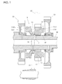
Fig. 1 is a drawing showing a usage example of a shifter gear of one embodiment according to the present invention. -
Fig. 2(a) is a partially enlarged cross-sectional view of the shifter gear of one embodiment according to the present invention. -
Fig. 2(b) is a partially omitted side view of a splined collar. -
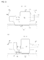
Figs. 3(a) and 3(b) are action explanatory diagrams. - An embodiment of a shifter gear according to the present invention will be described below by referring to the accompanying drawings. Like reference signs designate corresponding or identical components throughout the respective drawings.
- As shown in
Fig. 1 andFig. 2 (mainlyFig. 2 ), ashifter gear 10 of this embodiment includes abase part 11, agear part 12, anengaging part 13 with ashift fork 30, and aspline 14. Thegear part 12 is disposed at the outer periphery of thisbase part 11. Theengaging part 13 is disposed at the outer periphery of thebase part 11. Thespline 14 is disposed at the inner periphery of thebase part 11. - As shown in
Fig. 1 , thisshifter gear 10 is mounted to be relatively slidable in an axis direction and incapable of relative rotation around the axis to agear shift shaft 40 via thespline 14. Thegear shift shaft 40 rotates by a power from a power source.Reference sign 42 denotes a spline of thegear shift shaft 40. With theshifter gear 10, thegear part 12 meshes with a gear G1. Theshift fork 30, which engages the engagingpart 13, performs a slide operation on theshifter gear 10. Theshifter gear 10 selectively engages the adjacent gear G2 or an adjacent gear G3 with a dowel to transmit the power while shifting the gear. 11d2 and 11d3 are dowels of theshifter gear 10. G2d is a dowel hole of the gear G2 that can engage and disengage the dowel 11d2. G3d is a dowel hole of the gear G3 that can engage and disengage the dowel 11d3. - As shown in
Fig. 2 , with theshifter gear 10, onepart 14c of thespline 14 is configured with asplined collar 20 in the axis direction (the right-left direction inFig. 2 ). Thesplined collar 20 is a different body from thebase part 11. Thesplined collar 20 can relatively rotate to thebase part 11 around the axis. - With this
shifter gear 10, the onepart 14c of thespline 14 is configured with thesplined collar 20 in the axis direction. Thesplined collar 20 is a different body from thebase part 11. Thesplined collar 20 can relatively rotate to thebase part 11 around the axis. Accordingly, the onepart 14c of thespline 14, which is configured with thissplined collar 20, basically does not act as a power transmission unit (except for extremely slight power transmission caused by a friction between thebase part 11 and the splined collar 20). - This allows decreasing an amount of offset E1 between a center C1 of the
gear part 12 as the power transmission unit (seeFig. 3(b) ) and a center C2 of thespline 14 as the power transmission unit as much as possible. This reduces a thrust load (F3) that occurs in theshifter gear 10, ensuring restraining the friction between theshifter gear 10 and theshift fork 30. It is to be noted that, although thesplined collar 20 does not act as the power transmission unit, thesplined collar 20 serves as a supporting part that prevents theshifter gear 10 from falling over in the axial direction. - Just to make sure, the following further describes the action of the
shifter gear 10 of this embodiment referring toFig. 3. Fig. 3(a) is a drawing showing a comparative example (a shifter gear equivalent to the conventional technology). Ashifter gear 100 includes abase part 111, agear part 112, anengaging part 113 with a shift fork, and aspline 114. Thegear part 112 is disposed at the outer periphery of thisbase part 111. Theengaging part 113 is disposed at the outer periphery of thebase part 111. Thespline 114 is disposed at the inner periphery of thebase part 111. - With such a
shifter gear 100, to perform the slide operation by the shift fork, a sliding force F4' or F5' acts on theengaging part 113 with the shift fork. These sliding forces F4' and F5' act as a force M4' or M5', which are forces attempting to fall over theshifter gear 100 in the axial direction. Accordingly, to receive the forces, thespline 114 is disposed not only at a part corresponding to thegear part 112 but also at a part corresponding to theengaging part 113 with the shift fork. - With the
conventional shifter gear 100, theentire spline 114 is integrally configured with thebase part 111, serving as the power transmission unit. Hence, with theconventional shifter gear 100, an amount of offset E2 between a center C1' of the gear part as the power transmission unit and a center C2' of the spline as the power transmission unit is large in the axis direction. Accordingly, due to a load balance of an input and an output F1' and F2' of the power, a load F3' is likely to occur in theshifter gear 100 in the thrust direction. Such thrust load F3' causes a friction at theengaging part 113 between the shift fork and the shifter gear. Furthermore, the thrust load F3' also acts as a force M', which is a force attempting to fall over theshifter gear 100 in the axial direction, further facilitating the friction. - In contrast to this, as shown in
Fig. 3(b) , with theshifter gear 10 of this embodiment, the onepart 14c of thespline 14 is configured with thesplined collar 20 in the axis direction. Thesplined collar 20 is a different body from thebase part 11. Thesplined collar 20 can relatively rotate to thebase part 11 around the axis. Accordingly, the onepart 14c of thespline 14, which is configured with thissplined collar 20, basically does not act as the power transmission unit (except for extremely slight power transmission caused by the friction between thebase part 11 and the splined collar 20). - This allows decreasing the amount of offset E1 between the center C1 of the
gear part 12 as the power transmission unit and the center C2 of thespline 14 as the power transmission unit (The center C1 of thegear part 12 can be matched with the center C2 of thespline 14 as the power transmission unit. In the case, the amount of offset E1 becomes 0). This reduces the thrust load F3 that occurs in theshifter gear 10, ensuring restraining the friction between theshifter gear 10 and theshift fork 30. - It is to be noted that, with the
shifter gear 10 of this embodiment as well, to perform the slide operation by the shift fork, a sliding force F4 or F5 acts on the engagingpart 13 with the shift fork. These sliding forces F4 and F5 act as a force M4 or M5, which is the force attempting to fall over theshifter gear 10 in the axial direction. However, thesplined collar 20 can receive the force M4 or M5. That is, thesplined collar 20 does not act as the power transmission unit. However, thesplined collar 20 serves as the supporting part, which prevents theshifter gear 10 from falling over in the axial direction. The slide operation causes theshifter gear 10 to selectively engage the adjacent gear G2 or G3 inFig. 1 . Furthermore, thegear part 12 performs power transmission with the gear G1. Thegear shift shaft 40 may be a driving shaft or a driven shaft. - As shown in
Fig. 1 andFig. 2 , thesplined collar 20 is disposed at a position displaced off from thegear part 12 in the axis direction. With this configuration, thesplined collar 20 can effectively prevent theshifter gear 10 from falling over in the axial direction. - Moreover, the
splined collar 20 is disposed on the opposite side from thegear part 12 in the axis direction sandwiching the engagingpart 13 with theshift fork 30. With this configuration, thesplined collar 20 can effectively prevent theshifter gear 10 from falling over in the axial direction. - The
splined collar 20 includes anoil passage 21. Theoil passage 21 supplies lubricating oil to the engagingpart 13 with theshift fork 30. This configuration supplies the lubricating oil to the part between theshift fork 30 and theengaging part 13, ensuring effectively restraining the friction between the both. Theoil passage 21 includes anorifice 22 and anoil passage 23 with a circular, recessed groove shape. Theorifice 22 communicates with anoil passage 41 of thegear shift shaft 40. Theoil passage 23 communicates with thisorifice 22 and communicates with anoil passage 15 at thebase part 11. - A
stopper 16 is disposed at thebase part 11 so as to be attachable/removable to thebase part 11. Thestopper 16 prevents thesplined collar 20 from coming off in the axis direction. This configuration allows enhancing assembility of thesplined collar 20 to thebase part 11. Thestopper 16 can be configured of a round clip. - The embodiments of the present invention have been described above. The present invention is not limited to the above-described embodiments. Modifications can be appropriately made without departing from the scope of the gist of the present invention.
-
- 10... Shifter gear
- 11... Base part
- 12... Gear part
- 13... Engaging part with the shift fork
- 14... Spline
- 14c... One part of the spline
- 16... Stopper
- 20... Splined collar
- 21... Oil passage
- 30... Shift fork
- 40... Gear shift shaft
Claims (5)
- A shifter gear (10) comprising:a base part (11);a gear part (12) disposed at an outer periphery of the base part (11);an engaging part (13) with a shift fork (30) disposed at an outer periphery of the base part (11); anda spline (14) disposed at an inner periphery of the base part (11),the shifter gear (10) being mounted relatively slidable to a gear shift shaft (40) in an axis direction via the spline (14), the shifter gear (10) being mounted to be incapable of relative rotation around an axis, and the shift fork (30) engaging the engaging part (13) being configured to perform a slide operation on the shifter gear (10),
wherein one part (14c) of the spline (14) is configured with a splined collar (20) in an axis direction, the splined collar (20) being a different body from the base part (11), the splined collar (20) being able to relatively rotate to the base part (11) around an axis. - The shifter gear according to claim 1, wherein the splined collar (20) is disposed at a position displaced off from the gear part (12) in an axis direction.
- The shifter gear according to claim 1 or 2, wherein the splined collar (20) is disposed on an opposite side from the gear part (12) in an axis direction sandwiching the engaging part (13) with the shift fork (30).
- The shifter gear according to any one of claims 1 to 3, wherein the splined collar (20) includes an oil passage (21), the oil passage (21) being configured to supply lubricating oil to the engaging part (13) with the shift fork (30).
- The shifter gear according to any one of claims 1 to 4, wherein the base part (11) is provided with a stopper (16) that is attachable/removable to the base part (11), the stopper 16 being configured to prevent the splined collar (20) from coming off in an axis direction.
Applications Claiming Priority (1)
| Application Number | Priority Date | Filing Date | Title |
|---|---|---|---|
| JP2014200012A JP6078508B2 (en) | 2014-09-30 | 2014-09-30 | Shifter gear |
Publications (2)
| Publication Number | Publication Date |
|---|---|
| EP3002481A1 true EP3002481A1 (en) | 2016-04-06 |
| EP3002481B1 EP3002481B1 (en) | 2020-03-11 |
Family
ID=54199020
Family Applications (1)
| Application Number | Title | Priority Date | Filing Date |
|---|---|---|---|
| EP15186533.4A Active EP3002481B1 (en) | 2014-09-30 | 2015-09-23 | Shifter gear |
Country Status (3)
| Country | Link |
|---|---|
| US (1) | US10054197B2 (en) |
| EP (1) | EP3002481B1 (en) |
| JP (1) | JP6078508B2 (en) |
Families Citing this family (3)
| Publication number | Priority date | Publication date | Assignee | Title |
|---|---|---|---|---|
| US20160097445A1 (en) * | 2014-10-01 | 2016-04-07 | Borgwarner Inc. | Lubrication system for transfer case |
| CA2967861C (en) | 2014-12-17 | 2021-11-30 | H.B. Fuller Company | Hot melt adhesive composition for bonding packs of metal containers |
| ES2844498T3 (en) | 2014-12-17 | 2021-07-22 | Fuller H B Co | Hot melt adhesive composition for joining packaged assemblies of plastic containers |
Citations (3)
| Publication number | Priority date | Publication date | Assignee | Title |
|---|---|---|---|---|
| JPS63187726U (en) * | 1987-05-26 | 1988-12-01 | ||
| JP2007162819A (en) * | 2005-12-13 | 2007-06-28 | Yamaha Motor Co Ltd | Transmission mechanism and vehicle including the transmission mechanism |
| JP2011208766A (en) | 2010-03-30 | 2011-10-20 | Honda Motor Co Ltd | Transmission system for vehicle |
Family Cites Families (7)
| Publication number | Priority date | Publication date | Assignee | Title |
|---|---|---|---|---|
| DE1813621B2 (en) * | 1968-12-10 | 1972-12-21 | Volkswagenwerk Ag, 3180 Wolfsburg | DEVICE FOR LIMITING THE SHIFTING TRAVEL OF A SLIDING SOCKET DESIGNED FOR GEARSHIFTING AND SYNCHRONIZING DEVICES, IN PARTICULAR FOR MOTOR VEHICLES |
| DE6900376U (en) * | 1969-01-07 | 1969-06-19 | Opel Adam Ag | SYNCHRONIZATION DEVICE FOR STEP-BY-STEP TRANSMISSIONS OF MOTOR VEHICLES |
| CA1262102A (en) * | 1984-06-14 | 1989-10-03 | Sadanori Nishimura | Inertia lock type synchronous clutch mechanism |
| JP4170534B2 (en) * | 1999-09-03 | 2008-10-22 | 本田技研工業株式会社 | transmission |
| JP2001208766A (en) | 2000-01-28 | 2001-08-03 | Toyota Central Res & Dev Lab Inc | Acceleration detector |
| JP5557567B2 (en) * | 2010-03-23 | 2014-07-23 | 本田技研工業株式会社 | Gearbox for internal combustion engine |
| JP5400916B2 (en) * | 2012-03-19 | 2014-01-29 | 本田技研工業株式会社 | Transmission synchronizer |
-
2014
- 2014-09-30 JP JP2014200012A patent/JP6078508B2/en active Active
-
2015
- 2015-09-23 EP EP15186533.4A patent/EP3002481B1/en active Active
- 2015-11-12 US US14/939,978 patent/US10054197B2/en active Active
Patent Citations (3)
| Publication number | Priority date | Publication date | Assignee | Title |
|---|---|---|---|---|
| JPS63187726U (en) * | 1987-05-26 | 1988-12-01 | ||
| JP2007162819A (en) * | 2005-12-13 | 2007-06-28 | Yamaha Motor Co Ltd | Transmission mechanism and vehicle including the transmission mechanism |
| JP2011208766A (en) | 2010-03-30 | 2011-10-20 | Honda Motor Co Ltd | Transmission system for vehicle |
Also Published As
| Publication number | Publication date |
|---|---|
| US20160245369A1 (en) | 2016-08-25 |
| EP3002481B1 (en) | 2020-03-11 |
| JP2016070361A (en) | 2016-05-09 |
| US10054197B2 (en) | 2018-08-21 |
| JP6078508B2 (en) | 2017-02-08 |
Similar Documents
| Publication | Publication Date | Title |
|---|---|---|
| US8919515B2 (en) | Clutch device | |
| US9011289B2 (en) | Transmission clutch assembly | |
| US9657828B2 (en) | Driveline component having differential and park lock mechanism | |
| JP2007534899A (en) | Dual clutch transmission for automobile | |
| EP3002481B1 (en) | Shifter gear | |
| EP1826431A3 (en) | Shift device with synchronizer adapted for transmission | |
| DE102010060890B4 (en) | Synchronizing device for a transmission | |
| EP2772657A3 (en) | Transmission shift device | |
| EP3141779A3 (en) | Power transmission apparatus | |
| US20130239718A1 (en) | Synchronizer for transmission | |
| US20160010728A1 (en) | Transmission assembly for a motor vehicle and motor vehicle | |
| RU2013140405A (en) | COUPLING ELEMENT EXECUTED WITH THE OPPORTUNITY TO REMAIN LOCKING IN A FIXED POSITION UNDER HEAVY LOAD | |
| RU2016122631A (en) | MECHANICAL GEARBOX | |
| EP3093180A3 (en) | Dropbox assembly for transmission of work vehicle | |
| US20220163097A1 (en) | Shiftable Planetary Gear Train | |
| US8991583B2 (en) | Spring pack for a transmission | |
| CN105987092B (en) | Speed-changing operation device, speed changer and plate | |
| US9593763B2 (en) | Gearing assembly having a planetary stage | |
| US9534684B2 (en) | Shift device having rotational free travel for the shift shaft, and motor vehicle transmission having such shift device | |
| US9631701B2 (en) | Planetary gearset | |
| JP2012127446A (en) | Transmission | |
| JP2015081650A (en) | Automatic transmission | |
| KR101628721B1 (en) | Auto transmission apparatus | |
| CN203040199U (en) | Flexible shaft control mechanism of corn harvesting machine gearbox | |
| WO2015038053A1 (en) | Synchromesh unit in a gearbox |
Legal Events
| Date | Code | Title | Description |
|---|---|---|---|
| PUAI | Public reference made under article 153(3) epc to a published international application that has entered the european phase |
Free format text: ORIGINAL CODE: 0009012 |
|
| 17P | Request for examination filed |
Effective date: 20150923 |
|
| AK | Designated contracting states |
Kind code of ref document: A1 Designated state(s): AL AT BE BG CH CY CZ DE DK EE ES FI FR GB GR HR HU IE IS IT LI LT LU LV MC MK MT NL NO PL PT RO RS SE SI SK SM TR |
|
| AX | Request for extension of the european patent |
Extension state: BA ME |
|
| RBV | Designated contracting states (corrected) |
Designated state(s): AL AT BE BG CH CY CZ DE DK EE ES FI FR GB GR HR HU IE IS IT LI LT LU LV MC MK MT NL NO PL PT RO RS SE SI SK SM TR |
|
| GRAP | Despatch of communication of intention to grant a patent |
Free format text: ORIGINAL CODE: EPIDOSNIGR1 |
|
| STAA | Information on the status of an ep patent application or granted ep patent |
Free format text: STATUS: GRANT OF PATENT IS INTENDED |
|
| RIC1 | Information provided on ipc code assigned before grant |
Ipc: F16H 3/22 20060101AFI20190924BHEP Ipc: F16H 3/16 20060101ALI20190924BHEP Ipc: F16H 55/17 20060101ALI20190924BHEP |
|
| INTG | Intention to grant announced |
Effective date: 20191015 |
|
| GRAS | Grant fee paid |
Free format text: ORIGINAL CODE: EPIDOSNIGR3 |
|
| GRAA | (expected) grant |
Free format text: ORIGINAL CODE: 0009210 |
|
| STAA | Information on the status of an ep patent application or granted ep patent |
Free format text: STATUS: THE PATENT HAS BEEN GRANTED |
|
| AK | Designated contracting states |
Kind code of ref document: B1 Designated state(s): AL AT BE BG CH CY CZ DE DK EE ES FI FR GB GR HR HU IE IS IT LI LT LU LV MC MK MT NL NO PL PT RO RS SE SI SK SM TR |
|
| REG | Reference to a national code |
Ref country code: GB Ref legal event code: FG4D |
|
| REG | Reference to a national code |
Ref country code: CH Ref legal event code: EP |
|
| REG | Reference to a national code |
Ref country code: AT Ref legal event code: REF Ref document number: 1243507 Country of ref document: AT Kind code of ref document: T Effective date: 20200315 |
|
| REG | Reference to a national code |
Ref country code: IE Ref legal event code: FG4D |
|
| REG | Reference to a national code |
Ref country code: DE Ref legal event code: R096 Ref document number: 602015048480 Country of ref document: DE |
|
| PG25 | Lapsed in a contracting state [announced via postgrant information from national office to epo] |
Ref country code: NO Free format text: LAPSE BECAUSE OF FAILURE TO SUBMIT A TRANSLATION OF THE DESCRIPTION OR TO PAY THE FEE WITHIN THE PRESCRIBED TIME-LIMIT Effective date: 20200611 Ref country code: RS Free format text: LAPSE BECAUSE OF FAILURE TO SUBMIT A TRANSLATION OF THE DESCRIPTION OR TO PAY THE FEE WITHIN THE PRESCRIBED TIME-LIMIT Effective date: 20200311 Ref country code: FI Free format text: LAPSE BECAUSE OF FAILURE TO SUBMIT A TRANSLATION OF THE DESCRIPTION OR TO PAY THE FEE WITHIN THE PRESCRIBED TIME-LIMIT Effective date: 20200311 |
|
| REG | Reference to a national code |
Ref country code: NL Ref legal event code: MP Effective date: 20200311 |
|
| PG25 | Lapsed in a contracting state [announced via postgrant information from national office to epo] |
Ref country code: GR Free format text: LAPSE BECAUSE OF FAILURE TO SUBMIT A TRANSLATION OF THE DESCRIPTION OR TO PAY THE FEE WITHIN THE PRESCRIBED TIME-LIMIT Effective date: 20200612 Ref country code: HR Free format text: LAPSE BECAUSE OF FAILURE TO SUBMIT A TRANSLATION OF THE DESCRIPTION OR TO PAY THE FEE WITHIN THE PRESCRIBED TIME-LIMIT Effective date: 20200311 Ref country code: LV Free format text: LAPSE BECAUSE OF FAILURE TO SUBMIT A TRANSLATION OF THE DESCRIPTION OR TO PAY THE FEE WITHIN THE PRESCRIBED TIME-LIMIT Effective date: 20200311 Ref country code: SE Free format text: LAPSE BECAUSE OF FAILURE TO SUBMIT A TRANSLATION OF THE DESCRIPTION OR TO PAY THE FEE WITHIN THE PRESCRIBED TIME-LIMIT Effective date: 20200311 Ref country code: BG Free format text: LAPSE BECAUSE OF FAILURE TO SUBMIT A TRANSLATION OF THE DESCRIPTION OR TO PAY THE FEE WITHIN THE PRESCRIBED TIME-LIMIT Effective date: 20200611 |
|
| REG | Reference to a national code |
Ref country code: LT Ref legal event code: MG4D |
|
| PG25 | Lapsed in a contracting state [announced via postgrant information from national office to epo] |
Ref country code: NL Free format text: LAPSE BECAUSE OF FAILURE TO SUBMIT A TRANSLATION OF THE DESCRIPTION OR TO PAY THE FEE WITHIN THE PRESCRIBED TIME-LIMIT Effective date: 20200311 |
|
| PG25 | Lapsed in a contracting state [announced via postgrant information from national office to epo] |
Ref country code: CZ Free format text: LAPSE BECAUSE OF FAILURE TO SUBMIT A TRANSLATION OF THE DESCRIPTION OR TO PAY THE FEE WITHIN THE PRESCRIBED TIME-LIMIT Effective date: 20200311 Ref country code: LT Free format text: LAPSE BECAUSE OF FAILURE TO SUBMIT A TRANSLATION OF THE DESCRIPTION OR TO PAY THE FEE WITHIN THE PRESCRIBED TIME-LIMIT Effective date: 20200311 Ref country code: SM Free format text: LAPSE BECAUSE OF FAILURE TO SUBMIT A TRANSLATION OF THE DESCRIPTION OR TO PAY THE FEE WITHIN THE PRESCRIBED TIME-LIMIT Effective date: 20200311 Ref country code: SK Free format text: LAPSE BECAUSE OF FAILURE TO SUBMIT A TRANSLATION OF THE DESCRIPTION OR TO PAY THE FEE WITHIN THE PRESCRIBED TIME-LIMIT Effective date: 20200311 Ref country code: IS Free format text: LAPSE BECAUSE OF FAILURE TO SUBMIT A TRANSLATION OF THE DESCRIPTION OR TO PAY THE FEE WITHIN THE PRESCRIBED TIME-LIMIT Effective date: 20200711 Ref country code: RO Free format text: LAPSE BECAUSE OF FAILURE TO SUBMIT A TRANSLATION OF THE DESCRIPTION OR TO PAY THE FEE WITHIN THE PRESCRIBED TIME-LIMIT Effective date: 20200311 Ref country code: PT Free format text: LAPSE BECAUSE OF FAILURE TO SUBMIT A TRANSLATION OF THE DESCRIPTION OR TO PAY THE FEE WITHIN THE PRESCRIBED TIME-LIMIT Effective date: 20200805 Ref country code: EE Free format text: LAPSE BECAUSE OF FAILURE TO SUBMIT A TRANSLATION OF THE DESCRIPTION OR TO PAY THE FEE WITHIN THE PRESCRIBED TIME-LIMIT Effective date: 20200311 |
|
| REG | Reference to a national code |
Ref country code: AT Ref legal event code: MK05 Ref document number: 1243507 Country of ref document: AT Kind code of ref document: T Effective date: 20200311 |
|
| REG | Reference to a national code |
Ref country code: DE Ref legal event code: R097 Ref document number: 602015048480 Country of ref document: DE |
|
| PLBE | No opposition filed within time limit |
Free format text: ORIGINAL CODE: 0009261 |
|
| STAA | Information on the status of an ep patent application or granted ep patent |
Free format text: STATUS: NO OPPOSITION FILED WITHIN TIME LIMIT |
|
| PG25 | Lapsed in a contracting state [announced via postgrant information from national office to epo] |
Ref country code: ES Free format text: LAPSE BECAUSE OF FAILURE TO SUBMIT A TRANSLATION OF THE DESCRIPTION OR TO PAY THE FEE WITHIN THE PRESCRIBED TIME-LIMIT Effective date: 20200311 Ref country code: AT Free format text: LAPSE BECAUSE OF FAILURE TO SUBMIT A TRANSLATION OF THE DESCRIPTION OR TO PAY THE FEE WITHIN THE PRESCRIBED TIME-LIMIT Effective date: 20200311 Ref country code: DK Free format text: LAPSE BECAUSE OF FAILURE TO SUBMIT A TRANSLATION OF THE DESCRIPTION OR TO PAY THE FEE WITHIN THE PRESCRIBED TIME-LIMIT Effective date: 20200311 Ref country code: IT Free format text: LAPSE BECAUSE OF FAILURE TO SUBMIT A TRANSLATION OF THE DESCRIPTION OR TO PAY THE FEE WITHIN THE PRESCRIBED TIME-LIMIT Effective date: 20200311 |
|
| 26N | No opposition filed |
Effective date: 20201214 |
|
| PG25 | Lapsed in a contracting state [announced via postgrant information from national office to epo] |
Ref country code: PL Free format text: LAPSE BECAUSE OF FAILURE TO SUBMIT A TRANSLATION OF THE DESCRIPTION OR TO PAY THE FEE WITHIN THE PRESCRIBED TIME-LIMIT Effective date: 20200311 Ref country code: SI Free format text: LAPSE BECAUSE OF FAILURE TO SUBMIT A TRANSLATION OF THE DESCRIPTION OR TO PAY THE FEE WITHIN THE PRESCRIBED TIME-LIMIT Effective date: 20200311 |
|
| PG25 | Lapsed in a contracting state [announced via postgrant information from national office to epo] |
Ref country code: MC Free format text: LAPSE BECAUSE OF FAILURE TO SUBMIT A TRANSLATION OF THE DESCRIPTION OR TO PAY THE FEE WITHIN THE PRESCRIBED TIME-LIMIT Effective date: 20200311 |
|
| REG | Reference to a national code |
Ref country code: CH Ref legal event code: PL |
|
| GBPC | Gb: european patent ceased through non-payment of renewal fee |
Effective date: 20200923 |
|
| REG | Reference to a national code |
Ref country code: BE Ref legal event code: MM Effective date: 20200930 |
|
| PG25 | Lapsed in a contracting state [announced via postgrant information from national office to epo] |
Ref country code: LU Free format text: LAPSE BECAUSE OF NON-PAYMENT OF DUE FEES Effective date: 20200923 |
|
| PG25 | Lapsed in a contracting state [announced via postgrant information from national office to epo] |
Ref country code: FR Free format text: LAPSE BECAUSE OF NON-PAYMENT OF DUE FEES Effective date: 20200930 |
|
| REG | Reference to a national code |
Ref country code: DE Ref legal event code: R084 Ref document number: 602015048480 Country of ref document: DE |
|
| PG25 | Lapsed in a contracting state [announced via postgrant information from national office to epo] |
Ref country code: CH Free format text: LAPSE BECAUSE OF NON-PAYMENT OF DUE FEES Effective date: 20200930 Ref country code: BE Free format text: LAPSE BECAUSE OF NON-PAYMENT OF DUE FEES Effective date: 20200930 Ref country code: IE Free format text: LAPSE BECAUSE OF NON-PAYMENT OF DUE FEES Effective date: 20200923 Ref country code: LI Free format text: LAPSE BECAUSE OF NON-PAYMENT OF DUE FEES Effective date: 20200930 Ref country code: GB Free format text: LAPSE BECAUSE OF NON-PAYMENT OF DUE FEES Effective date: 20200923 |
|
| PG25 | Lapsed in a contracting state [announced via postgrant information from national office to epo] |
Ref country code: TR Free format text: LAPSE BECAUSE OF FAILURE TO SUBMIT A TRANSLATION OF THE DESCRIPTION OR TO PAY THE FEE WITHIN THE PRESCRIBED TIME-LIMIT Effective date: 20200311 Ref country code: MT Free format text: LAPSE BECAUSE OF FAILURE TO SUBMIT A TRANSLATION OF THE DESCRIPTION OR TO PAY THE FEE WITHIN THE PRESCRIBED TIME-LIMIT Effective date: 20200311 Ref country code: CY Free format text: LAPSE BECAUSE OF FAILURE TO SUBMIT A TRANSLATION OF THE DESCRIPTION OR TO PAY THE FEE WITHIN THE PRESCRIBED TIME-LIMIT Effective date: 20200311 |
|
| PG25 | Lapsed in a contracting state [announced via postgrant information from national office to epo] |
Ref country code: MK Free format text: LAPSE BECAUSE OF FAILURE TO SUBMIT A TRANSLATION OF THE DESCRIPTION OR TO PAY THE FEE WITHIN THE PRESCRIBED TIME-LIMIT Effective date: 20200311 Ref country code: AL Free format text: LAPSE BECAUSE OF FAILURE TO SUBMIT A TRANSLATION OF THE DESCRIPTION OR TO PAY THE FEE WITHIN THE PRESCRIBED TIME-LIMIT Effective date: 20200311 |
|
| PGFP | Annual fee paid to national office [announced via postgrant information from national office to epo] |
Ref country code: DE Payment date: 20240820 Year of fee payment: 10 |
|
| REG | Reference to a national code |
Ref country code: DE Ref legal event code: R119 Ref document number: 602015048480 Country of ref document: DE |
|
| PG25 | Lapsed in a contracting state [announced via postgrant information from national office to epo] |
Ref country code: DE Free format text: LAPSE BECAUSE OF NON-PAYMENT OF DUE FEES Effective date: 20260401 |