EP3002477A1 - Diaphragm unit and suspension - Google Patents
Diaphragm unit and suspension Download PDFInfo
- Publication number
- EP3002477A1 EP3002477A1 EP15187039.1A EP15187039A EP3002477A1 EP 3002477 A1 EP3002477 A1 EP 3002477A1 EP 15187039 A EP15187039 A EP 15187039A EP 3002477 A1 EP3002477 A1 EP 3002477A1
- Authority
- EP
- European Patent Office
- Prior art keywords
- rod
- cylinder
- piston rod
- diaphragm
- piston
- Prior art date
- Legal status (The legal status is an assumption and is not a legal conclusion. Google has not performed a legal analysis and makes no representation as to the accuracy of the status listed.)
- Granted
Links
Images



Classifications
-
- B—PERFORMING OPERATIONS; TRANSPORTING
- B62—LAND VEHICLES FOR TRAVELLING OTHERWISE THAN ON RAILS
- B62K—CYCLES; CYCLE FRAMES; CYCLE STEERING DEVICES; RIDER-OPERATED TERMINAL CONTROLS SPECIALLY ADAPTED FOR CYCLES; CYCLE AXLE SUSPENSIONS; CYCLE SIDECARS, FORECARS, OR THE LIKE
- B62K25/00—Axle suspensions
- B62K25/04—Axle suspensions for mounting axles resiliently on cycle frame or fork
- B62K25/28—Axle suspensions for mounting axles resiliently on cycle frame or fork with pivoted chain-stay
- B62K25/283—Axle suspensions for mounting axles resiliently on cycle frame or fork with pivoted chain-stay for cycles without a pedal crank, e.g. motorcycles
-
- B—PERFORMING OPERATIONS; TRANSPORTING
- B60—VEHICLES IN GENERAL
- B60C—VEHICLE TYRES; TYRE INFLATION; TYRE CHANGING; CONNECTING VALVES TO INFLATABLE ELASTIC BODIES IN GENERAL; DEVICES OR ARRANGEMENTS RELATED TO TYRES
- B60C15/00—Tyre beads, e.g. ply turn-up or overlap
- B60C15/06—Flipper strips, fillers, or chafing strips and reinforcing layers for the construction of the bead
-
- B—PERFORMING OPERATIONS; TRANSPORTING
- B60—VEHICLES IN GENERAL
- B60G—VEHICLE SUSPENSION ARRANGEMENTS
- B60G15/00—Resilient suspensions characterised by arrangement, location or type of combined spring and vibration damper, e.g. telescopic type
- B60G15/02—Resilient suspensions characterised by arrangement, location or type of combined spring and vibration damper, e.g. telescopic type having mechanical spring
- B60G15/06—Resilient suspensions characterised by arrangement, location or type of combined spring and vibration damper, e.g. telescopic type having mechanical spring and fluid damper
-
- B—PERFORMING OPERATIONS; TRANSPORTING
- B60—VEHICLES IN GENERAL
- B60G—VEHICLE SUSPENSION ARRANGEMENTS
- B60G15/00—Resilient suspensions characterised by arrangement, location or type of combined spring and vibration damper, e.g. telescopic type
- B60G15/08—Resilient suspensions characterised by arrangement, location or type of combined spring and vibration damper, e.g. telescopic type having fluid spring
- B60G15/12—Resilient suspensions characterised by arrangement, location or type of combined spring and vibration damper, e.g. telescopic type having fluid spring and fluid damper
-
- F—MECHANICAL ENGINEERING; LIGHTING; HEATING; WEAPONS; BLASTING
- F16—ENGINEERING ELEMENTS AND UNITS; GENERAL MEASURES FOR PRODUCING AND MAINTAINING EFFECTIVE FUNCTIONING OF MACHINES OR INSTALLATIONS; THERMAL INSULATION IN GENERAL
- F16F—SPRINGS; SHOCK-ABSORBERS; MEANS FOR DAMPING VIBRATION
- F16F13/00—Units comprising springs of the non-fluid type as well as vibration-dampers, shock-absorbers, or fluid springs
- F16F13/002—Units comprising springs of the non-fluid type as well as vibration-dampers, shock-absorbers, or fluid springs comprising at least one fluid spring
-
- F—MECHANICAL ENGINEERING; LIGHTING; HEATING; WEAPONS; BLASTING
- F16—ENGINEERING ELEMENTS AND UNITS; GENERAL MEASURES FOR PRODUCING AND MAINTAINING EFFECTIVE FUNCTIONING OF MACHINES OR INSTALLATIONS; THERMAL INSULATION IN GENERAL
- F16F—SPRINGS; SHOCK-ABSORBERS; MEANS FOR DAMPING VIBRATION
- F16F9/00—Springs, vibration-dampers, shock-absorbers, or similarly-constructed movement-dampers using a fluid or the equivalent as damping medium
- F16F9/02—Springs, vibration-dampers, shock-absorbers, or similarly-constructed movement-dampers using a fluid or the equivalent as damping medium using gas only or vacuum
- F16F9/04—Springs, vibration-dampers, shock-absorbers, or similarly-constructed movement-dampers using a fluid or the equivalent as damping medium using gas only or vacuum in a chamber with a flexible wall
- F16F9/0454—Springs, vibration-dampers, shock-absorbers, or similarly-constructed movement-dampers using a fluid or the equivalent as damping medium using gas only or vacuum in a chamber with a flexible wall characterised by the assembling method or by the mounting arrangement, e.g. mounting of the membrane
-
- F—MECHANICAL ENGINEERING; LIGHTING; HEATING; WEAPONS; BLASTING
- F16—ENGINEERING ELEMENTS AND UNITS; GENERAL MEASURES FOR PRODUCING AND MAINTAINING EFFECTIVE FUNCTIONING OF MACHINES OR INSTALLATIONS; THERMAL INSULATION IN GENERAL
- F16F—SPRINGS; SHOCK-ABSORBERS; MEANS FOR DAMPING VIBRATION
- F16F9/00—Springs, vibration-dampers, shock-absorbers, or similarly-constructed movement-dampers using a fluid or the equivalent as damping medium
- F16F9/02—Springs, vibration-dampers, shock-absorbers, or similarly-constructed movement-dampers using a fluid or the equivalent as damping medium using gas only or vacuum
- F16F9/04—Springs, vibration-dampers, shock-absorbers, or similarly-constructed movement-dampers using a fluid or the equivalent as damping medium using gas only or vacuum in a chamber with a flexible wall
- F16F9/05—Springs, vibration-dampers, shock-absorbers, or similarly-constructed movement-dampers using a fluid or the equivalent as damping medium using gas only or vacuum in a chamber with a flexible wall the flexible wall being of the rolling diaphragm type
-
- B—PERFORMING OPERATIONS; TRANSPORTING
- B60—VEHICLES IN GENERAL
- B60G—VEHICLE SUSPENSION ARRANGEMENTS
- B60G2202/00—Indexing codes relating to the type of spring, damper or actuator
- B60G2202/30—Spring/Damper and/or actuator Units
- B60G2202/31—Spring/Damper and/or actuator Units with the spring arranged around the damper, e.g. MacPherson strut
- B60G2202/314—The spring being a pneumatic spring
Definitions
- the present invention relates to a diaphragm unit and a suspension.
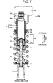
- FIG. 7 is a view showing a vertical cross section of a suspension 200 provided on a rear-wheel side of the motorcycle in the related art.
- the suspension 200 in the related art includes a cylinder 210 attached to a vehicle body side and a piston rod 220 attached to the axle side and slidably inserted into an oil chamber 216 of the cylinder 210 as shown in Fig. 7 .
- the suspension 200 further includes a coil spring 230 provided in outer peripheries of the cylinder 210 and the piston rod 220.
- the cylinder 210 has a double tube structure including an outer cylinder 210a and an inner cylinder 210b, having a vehicle body side mounting member 211 above the outer cylinder 210a.
- a piston 222 fixed by a nut 221 is provided on an upper side of the piston rod 220, and an axle side mounting member 223 is provided on a lower side thereof.
- a spring load adjustment nut 231 is arranged in the outer periphery of the cylinder 210, and a spring bearing 232 supported by the spring load adjustment nut 231.
- a spring bearing 234 is provided on an upper side of the axle side mounting member 223.
- a spring bearing guide 233 is provided in an outer side portion of the spring bearing 234.
- the coil spring 230 is provided between the spring bearing 232 and the spring bearing guide 233.
- a lower part of the cylinder 210 is opened, and a rod guide 212 through which the piston rod 220 pierces is provided in an opening thereof as shown in Fig. 7 .
- the rod guide 212 has an annular shape and provided at an inner peripheral portion of the cylinder 210 in a liquid tight manner.
- An oil seal 213 is provided at an inner peripheral portion of the rod guide 212, which allows the piston rod 220 to slide freely in a liquid tight manner.
- An end plate 214 is provided in the opening of the cylinder 210 which is under the rod guide 212. An upper end surface of the end plate 214 abuts on the rod guide 212.
- the end plate 214 has an annular shape and is provided in the inner peripheral portion of the cylinder 210 in the liquid tight manner.
- a dust seal 215 is provided at an inner peripheral portion of the end plate 214, which prevents intrusion of dust.
- a damping force generating apparatus 240 and a reservoir 241 communicating to the damping force generating apparatus 240 are arranged in series on an upper portion of the outer cylinder 210a where the vehicle body side mounting member 211 is formed.
- the damping force generating apparatus 240 communicates to a piston side oil chamber 216a and a rod side oil chamber 216b inside the cylinder 210.
- the damping force generating apparatus 240 adjusts a compression side damping force and an extension side damping force.
- the reservoir 241 compensates volume of the piston rod 220 moving forward and backward in the oil chamber of the cylinder 210 (including volume increased by temperature expansion of oil).
- the piston 222 moves forward and backward in the oil chamber of the cylinder 210, thereby absorbing and damping vibration inputted from a road surface when a vehicle runs. Also, a spring force of the coil spring 230 absorbs an impact force received by the vehicle from the road surface and reduces transmission of vibration to the vehicle.
- the suspension there is air spring structure in which a diaphragm is provided around part of the cylinder and the piston rod 220 to form an air chamber and the reaction force is generated by using a pressure of the air inside the air chamber.
- the air spring structure is preferable to the coil spring structure for adjusting the reaction force easily and for improving the actuation performance of the stroke.
- Patent Document 1 JP-A-2007-203858
- the present invention has been made in view of the above, and an object thereof is to provide a diaphragm unit and a suspension including the diaphragm unit capable of changing the existing suspension having the coil spring structure to the suspension having the air spring structure easily.
- a diaphragm unit is detachably attached to a damper body, including: a cylinder in which a liquid is sealed; a piston rod having a piston sliding inside the cylinder on one end side of the piston rod, in which other end side of the piston rod is extended to an outside of the cylinder; and a rod guide having a bottomed cylindrical shape wherein an insertion opening into which the piston rod is inserted is provided at a bottom portion of the rod guide, the rod guide being fixed to a side of an opening of the cylinder into which the piston is inserted to thereby slidably insert the piston rod in a liquid tight manner.
- the diaphragm unit further includes an end member having a bottomed cylindrical shape wherein an insertion opening into which the piston rod is inserted is provided at a bottom portion of the end member, the end member being detachably fitted to an outer periphery of the cylinder or the rod guide so as to cover the opening of the cylinder or the rod guide, an air seal provided at an inner peripheral portion of the insertion opening of the end member, a rod side member having a bottomed cylindrical shape wherein an insertion opening into which the piston rod is inserted is provided at a bottom portion of the rod side member, the rod side member being provided in a position around the other end side of the piston rod, an annular bump rubber fixed to an inner bottom portion of the rod side member and having a through hole into which the piston rod is inserted, and a tubular diaphragm fixed to the end member at one end of the diaphragm and fixed to the rod side member at other end of the diaphragm.
- the present invention can provide a diaphragm unit and a suspension having the diaphragm unit capable of changing an existing suspension having a coil spring structure to a suspension having an air spring structure easily.
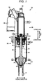
- Fig. 1 is a view showing a vertical cross section of a suspension 10 according to an embodiment.
- Fig. 2 is a view showing a vertical cross section of a damper body 20 of the suspension 10 according to the embodiment.
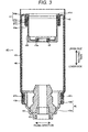
- Fig. 3 is a view showing a vertical cross section of a diaphragm unit 40 of the suspension 10 according to the embodiment.
- Fig. 1 and Fig. 2 show a state where the suspension 10 is extended to the maximum.
- the suspension 10 includes the damper body 20 and the diaphragm unit 40 as shown in Fig. 1 .
- the suspension 10 is a so-called damper with an air spring.
- the diaphragm unit 40 is attached to the damper body 20 so as to be detachable.
- the damper body 20 includes a cylinder 21, a piston rod 22 inserted into the cylinder 21 and a rod guide 23 supporting the piston rod 22 as shown in Fig. 1 and Fig. 2 .
- the cylinder 21 is formed in a double tube, for example, including an outer cylinder 21a and an inner cylinder 21b as shown in Fig. 2 .
- An upper end (upper end in an axial direction) of the outer cylinder 21a is closed and a lower end (lower end in the axial direction) of the outer cylinder 21a is opened.
- a communication hole (not shown) communicating to a later-described damping force generating apparatus 70 is formed in the upper end of the outer cylinder 21a.
- the cylinder 21 includes, for example, a vehicle body side mounting member 30 in an upper part (upper part in the axial direction) integrally.
- the axial direction means a direction of a center axis of the cylinder 21 and the piston rod 22 which have the same axis (the same applies hereinafter).
- An upper end and a lower end of the inner cylinder 21b are opened.
- the upper end of the inner cylinder 21b abuts on, for example, an upper-end inner surface of the outer cylinder 21a, and the lower end of the inner cylinder 21b abuts on a step portion in an upper-end inner periphery of the rod guide 23.
- the piston rod 22 has a piston 24 in an upper side (one end side) and an axle side mounting member 31 in a lower side (the other end side) protruding to an outside from the cylinder 21.
- the piston 24 is fixed by, for example, a nut 25, which is slidably inserted into the inner cylinder 21b of the cylinder 21.
- An oil chamber S in the inner cylinder 21b is sectioned into a piston side oil chamber S1 and a rod side oil chamber S2 by the piston 24.
- the axle side mounting member 31 is attached to a lower end of the piston rod 22 by, for example, screwing or the like so as to be detachable.
- the vehicle body side mounting member 30 is connected to the vehicle body side of the vehicle, and the axle side mounting member 31 is connected to the axle side of the vehicle, thereby interposing suspension 10 between the vehicle body and a swing arm mounted to a vehicle wheel.
- the damper body 20 exerts a damping force by relative movement in the axial direction, namely, extension/contraction of the cylinder 21 and the piston rod 22, thereby suppressing vibration of the vehicle body.
- the rod guide 23 is fixed to, for example, an inner periphery of an opening in the lower end of the outer cylinder 21a in a liquid tight manner as shown in Fig. 2 .
- the rod guide 23 includes a large-diameter cylindrical portion 23a in an upper part and a small-diameter cylindrical portion 23b in a lower part.
- the small-diameter cylindrical portion 23b has a bottom portion.
- the rod guide 23 has, for example, a bottomed cylindrical shape. In the bottom portion of the small-diameter cylindrical portion 23b, an insertion opening into which the piston rod 22 is inserted is provided.
- a center axis of the large-diameter cylindrical portion 23a and a center axis of the small-diameter cylindrical portion 23b are on the same axis.
- An oil seal 26 is provided at an inner peripheral portion of the small-diameter cylindrical portion 23b of the rod guide 23, which allows the piston rod 22 to be slidable in a liquid tight manner. Furthermore, for example, a lower end of the inner cylinder 21b is fitted into the large-diameter cylindrical portion 23a of the rod guide 23.
- the damper body 20 is provided with a rebound spring 27 restricting an extension side stroke around the piston rod 22 as well as between the piston 24 and the rod guide 23.
- the damping force generating apparatus 70 and a reservoir 80 communicating to the damping force generating apparatus 70 are provided in series in an upper part of the outer cylinder 21b where the vehicle body side mounting member 30 is formed.
- the damping force generating apparatus 70 communicates to the piston side oil chamber S1 and the rod side oil chamber S2 inside the cylinder 21.
- the reservoir 80 communicates to the piston side oil chamber S1 and the rod side oil chamber S2 through the damping force generating apparatus 70.
- the damping force generating apparatus 70 adjusts the compression-side damping force and the extension-side damping force.
- the reservoir 80 compensates volume of the piston rod 22 moving forward and backward in the oil chamber S of the cylinder 21 (including volume increased by temperature expansion of oil).
- the diaphragm unit 40 includes an end member 41, a rod side member 42, a diaphragm 43 and a bump rubber 44 as shown in Fig. 1 and Fig. 3 .
- the end member 41, the rod side member 42, the diaphragm 43 and the bump rubber 44 are formed as one unit.
- the unit configures the diaphragm unit 40 as a single unit. Accordingly, the diaphragm unit 40 can be attached to the damper body 20 and can be removed from the damper body 20 as the diaphragm unit 40 as the single unit.
- the end member 41 is detachably fitted to an outer periphery of the outer cylinder 21a so as to cover the opening of the outer cylinder 21a of the cylinder 21.
- the end member 41 has a bottomed cylindrical shape as shown in Fig. 3 .
- the end member 41 is formed so that, for example, an outer diameter of an opening side (upper part in the axial direction) is formed to be larger. That is, the end member 41 includes a small-diameter cylindrical portion 41a and a large-diameter cylindrical portion 41b, having the same inner diameter. Accordingly, a step portion 41c is formed in an outer side in the radial direction at a boundary between the small-diameter cylindrical portion 41a and the large-diameter cylindrical portion 41b. A center axis of the small-diameter cylindrical portion 41a and a center axis of the large-diameter cylindrical portion 41b are on the same axis.
- a groove portion 41d is formed in a circumferential direction.
- An air seal 45 is fitted to the groove portion 41d.
- the end member 41 is fitted to the outer periphery of the outer cylinder 21a in an air tight manner by the air seal 45.
- An opening through which the piston rod 22 pierces is provided at a bottom portion of the small-diameter cylindrical portion 41a.
- a groove portion 41e is formed in the circumferential direction.
- An air seal 46 is fitted to the groove portion 41e. The air seal 46 allows the piston rod 22 to be slidable in the air tight manner. Accordingly, an air flow into the end member 41 from a later-described air chamber 50 is prevented.
- a gap portion 90 is formed between an inner bottom portion of the end member 41 and an outer bottom portion of the rod guide 23 as shown in Fig. 1 .
- reaction force characteristics are affected when temperature of air of a later-described air chamber 50 changes.
- the gap portion 90 suppresses an amount of heat of the oil in the cylinder 21 to be transmitted to the air in the later-described air chamber 50. That is, the gap portion 90 functions also as a heat insulating portion. Therefore, it is possible to suppress the change in the temperature of the air in the air chamber 50 due to the temperature of oil inside the cylinder 21.
- the lower end of the outer cylinder 21a abuts on, for example, a step portion 41f in a lower-end inner surface of the end member 41.
- a space capacity of the gap portion 90 can be adjusted by adjusting height of the step portion 41f in the axial direction.
- the rod side member 42 is provided in a position to be a lower side of the piston rod 22.
- the rod side member 42 has a bottomed cylindrical shape including a small-diameter cylindrical portion 42a in a lower part and a large-diameter cylindrical portion 42b in an upper part.
- a bottom portion of the small-diameter cylindrical portion 42a an opening through which the lower side of the piston rod 22 pierces and supporting the piston rod 22 is formed.
- a lower end of the piston rod 22 is fixed to the axle side mounting member 31 through the opening of the small-diameter cylindrical portion 42a.
- a center axis of the small-diameter cylindrical portion 42a and a center axis of the large-diameter cylindrical portion 42b are on the same axis.
- the rod side member 42 is provided with a pressure adjusting portion (not shown) adjusting an internal pressure of the later-described air chamber 50.
- the air is filled in the air chamber 50 from, for example, an air source in an outside of the suspension 10 through the pressure adjusting portion.
- the diaphragm 43 is formed of a tubular elastic member.
- As the elastic member rubber and so on can be used.
- An upper end (one end) 43a of the diaphragm 43 is fixed to, for example, an outer peripheral surface of the small-diameter cylindrical portion 41a on the large-diameter cylindrical portion 41b side of the end member 41. That is, the upper end 43a of the diaphragm 43 is fixed to the outer peripheral surface of the small-diameter cylindrical portion 41a on the step portion 41c side. Accordingly, movement of the fixing portion to an upper side in the axial direction is prevented.
- a side surface of the end member 41 may be formed by one bottomed cylindrical body not including the large-diameter cylindrical portion 41b and the small-diameter cylindrical portion 41a.
- the upper end 43a of the diaphragm 43 is fixed to an outer side surface of the opening side (upper side) of the end member 41.
- a lower end (the other end) 43b of the diaphragm 43 is fixed to an outer peripheral surface of the large-diameter cylindrical portion 42b of the rod side member 42.
- a groove portion 42c is formed in a circumferential direction.
- a width of the groove portion 42c is set so as to correspond to a width of a later-described caulking band 47b.
- a mounting diameter of the large-diameter cylindrical portion 42b of the rod side member 42 to which the lower end 43b of the diaphragm 43 is fixed is set to be larger than a mounting diameter of the small-diameter cylindrical portion 41a of the end member 41 to which the upper end 43a of the diaphragm 43 is fixed in the diaphragm unit 40.
- An annular space is formed around the upper side (upper side in the axial direction) of the end member 41 in which the mounting diameter becomes smaller by using a difference in the mounting diameters.
- the annular space has an annular shape formed when a reverse U-shaped space is rotated around the center axis of the cylinder 21 and the piston rod 22.
- the diaphragm 43 is fixed to the end member 41 or the rod side member 42 by winding metal caulking bands 47a and 47b from the outer peripheral side and performing caulking.
- the caulking bands 47a and 47b may have, for example, a C-ring shape as well as an annular shape.
- the air chamber 50 is formed around the cylinder 21 (end member 41) and the piston rod 22.
- the air is filled in the air chamber 50 and hermetically sealed.
- the diaphragm 43 rolls outer peripheries of the large-diameter cylindrical portion 41b of the end member 41 and the outer cylinder 21a of the cylinder 21 in accordance with extension/contraction of the damper body 20.
- the air chamber 50 in which the air with a given pressure is filled configures an air spring which biases the damper body 20 in the extending direction. Accordingly, a spring force is generated in accordance with change of the volume in the air chamber 50 caused by extension/contraction of the damper body 20.
- the bump rubber 44 restricts a compression side stroke.
- the bump rubber 44 has a tubular shape, which is provided inside the rod side member 42 as well as around the piston rod 22.
- a through hole is formed in a center of the bump rubber 44.
- a lower end of the bump rubber 44 is fitted to an annular concave portion 42d formed in the small-diameter cylindrical portion 42a of the rod side member 42.
- the bump rubber 44 is formed of, for example, urethane, urethane foam, rubber and so on.
- An outer diameter of the small-diameter cylindrical portion 41a of the end member 41 is formed to be smaller than an inner diameter of the large-diameter cylindrical portion 42b of the rod side member 42, for example, for preventing contact between the end member 41 and the rod side member 42 in the compression-side stroke.
- the diaphragm unit 40 may also have a tubular cover 48 which covers the outer periphery of the diaphragm 43 as shown in Fig. 3 .
- a lower end (the other end) of the cover 48 is fixed to, for example, the large-diameter cylindrical portion 42b of the rod side member 42.
- An upper end (one end) of the cover 48 is open and is extended, for example, so as to pass an end portion of the diaphragm 43 on the upper side in the state where the suspension 10 is extended to the maximum as shown in Fig. 1 .
- the cover 48 is formed of, for example, a metal material, a resin material or the like. An outer periphery of the diaphragm 43 is covered by the cover 48 as described above, therefore, damage, abrasion and the like of the diaphragm 43 caused by dust, stones and so on can be prevented.
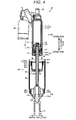
- Fig. 4 is an exploded vertical cross-section of the suspension 10 according to the embodiment. Fig. 4 shows the state where the suspension 10 is extended to the maximum.
- an end of the lower side of the piston rod 22 is inserted into an opening on the bottom portion of the end member 41 of the diaphragm unit 40.
- the diaphragm unit 40 is moved to the upper side (an arrow direction of Fig. 4 ) in the axial direction to insert the end of the lower side of the piston rod 22 into the through hole at the center of the bump rubber 44.
- the diaphragm unit 40 is further moved to the upper side in the axial direction, and the end member 41 is fitted around the outer cylinder 21a so as to cover the opening of the outer cylinder 21a of the cylinder 21.
- the end of the lower side of the piston rod 22 pierces through the bump rubber 44 and an opening in the bottom portion of the rod side member 42 to be extended to an outside of the rod side member 42.
- the axle side mounting member 31 is screwed to the end of the lower side of the piston rod 22 extended to the outside of the rod side member 42. Accordingly, the diaphragm unit 40 is mounted to the damper body 20 to have structure shown in Fig. 1 .
- the air chamber 50 is formed around the cylinder 21 (end member 41) and the piston rod 22.
- the air is filled in the air chamber 50 from the pressure adjusting portion (not shown) of the rod side member 42. Reaction force can be adjusted by adjusting the pressure in the air chamber 50.
- Fig. 5 is a view showing a vertical cross section of the suspension 10 according to the embodiment. Fig. 5 shows a state where the suspension 10 is contracted to the minimum.
- the air chamber 50 will be an annular space formed between the outer cylinder 21a of the cylinder 21 and the cover 48 as shown in Fig. 5 .
- the suspension 10 mounted on the vehicle continuously changes from the most extended state to the most contracted state because, for example, the suspension 10 repeats extension and contraction irregularly.
- the suspension 10 mounted on the vehicle is also in any state between the most extended state and the most contracted state.
- the diaphragm unit 40 according to the embodiment is formed so as to be attachable to and detachable from the damper body 20. Accordingly, for example, in an existing suspension including the coil spring, the diaphragm unit 40 according to the embodiment can be attached to the damper body by, for example, removing an end plate including a dust seal from a damper body. As described above, it is possible to change the existing suspension having the coil spring structure to the suspension having the air spring structure easily.
- the reaction force can be adjusted easily by adjusting the pressure in the air chamber 50.
- the air in the air chamber 50 is hardly affected by the temperature of the oil inside the cylinder 21 by providing the gap portion 90 between the inner bottom portion of the end member 41 and the outer bottom portion of the rod guide 23. Accordingly, it is possible to suppress change in the reaction characteristics in accordance with temperature change of the air in the air chamber 50.
- Fig. 6 is an enlarged view of a vertical cross section of a fitting portion with respect to the end member 41 in the suspension 10 according to another embodiment. It is also preferable that an annular groove portion 26c is provided around an outer peripheral portion of the rod guide 23 and that the outer cylinder 21a of the cylinder 21 is fitted to the groove portion 26c in the liquid tight manner as shown in Fig. 6 .
- the groove portion 26c has an annular shape formed when a U-shaped space is rotated around the center axis of the cylinder 21 and the piston rod 22.
- the end member 41 is detachably fitted to an outer periphery of the rod guide so as to cover the rod guide 23 as shown in Fig. 6 .
- a groove portion 41g is formed in an inner periphery portion of the small-diameter cylindrical portion 41a of the end member 41 in a circumferential direction.
- An air seal 49 is fitted to the groove portion 41g.
- the end member 41 is fitted to the outer periphery of the rod guide 23 in the air tight manner by the air seal 49.
- the upper end 43a of the diaphragm 43 is fixed, for example, to the outer peripheral surface of the small-diameter cylindrical portion 41a on the step portion 41c side in the same manner as the structure shown in Fig. 1 .
- the diaphragm unit 40 and the suspension 10 having the diaphragm unit 40 according to the embodiments can be applied to, for example, a rear suspension (rear cushion) of a motorcycle.
Landscapes
- Engineering & Computer Science (AREA)
- General Engineering & Computer Science (AREA)
- Mechanical Engineering (AREA)
- Fluid-Damping Devices (AREA)
- Vehicle Body Suspensions (AREA)
Abstract
Description
- The present invention relates to a diaphragm unit and a suspension.
- A motorcycle in a related art has a suspension from a standpoint of riding comfort and so on.
Fig. 7 is a view showing a vertical cross section of asuspension 200 provided on a rear-wheel side of the motorcycle in the related art. - The
suspension 200 in the related art includes acylinder 210 attached to a vehicle body side and apiston rod 220 attached to the axle side and slidably inserted into anoil chamber 216 of thecylinder 210 as shown inFig. 7 . Thesuspension 200 further includes acoil spring 230 provided in outer peripheries of thecylinder 210 and thepiston rod 220. - The
cylinder 210 has a double tube structure including anouter cylinder 210a and aninner cylinder 210b, having a vehicle bodyside mounting member 211 above theouter cylinder 210a. Apiston 222 fixed by anut 221 is provided on an upper side of thepiston rod 220, and an axleside mounting member 223 is provided on a lower side thereof. - A spring
load adjustment nut 231 is arranged in the outer periphery of thecylinder 210, and a spring bearing 232 supported by the springload adjustment nut 231. A spring bearing 234 is provided on an upper side of the axleside mounting member 223. In an outer side portion of the spring bearing 234, a spring bearingguide 233 is provided. Thecoil spring 230 is provided between the spring bearing 232 and thespring bearing guide 233. - A lower part of the
cylinder 210 is opened, and arod guide 212 through which thepiston rod 220 pierces is provided in an opening thereof as shown inFig. 7 . Therod guide 212 has an annular shape and provided at an inner peripheral portion of thecylinder 210 in a liquid tight manner. Anoil seal 213 is provided at an inner peripheral portion of therod guide 212, which allows thepiston rod 220 to slide freely in a liquid tight manner. - An
end plate 214 is provided in the opening of thecylinder 210 which is under therod guide 212. An upper end surface of theend plate 214 abuts on therod guide 212. Theend plate 214 has an annular shape and is provided in the inner peripheral portion of thecylinder 210 in the liquid tight manner. Adust seal 215 is provided at an inner peripheral portion of theend plate 214, which prevents intrusion of dust. - A damping
force generating apparatus 240 and areservoir 241 communicating to the dampingforce generating apparatus 240 are arranged in series on an upper portion of theouter cylinder 210a where the vehicle bodyside mounting member 211 is formed. The dampingforce generating apparatus 240 communicates to a pistonside oil chamber 216a and a rodside oil chamber 216b inside thecylinder 210. The dampingforce generating apparatus 240 adjusts a compression side damping force and an extension side damping force. Thereservoir 241 compensates volume of thepiston rod 220 moving forward and backward in the oil chamber of the cylinder 210 (including volume increased by temperature expansion of oil). - In the
suspension 200 in the related art having the above structure, thepiston 222 moves forward and backward in the oil chamber of thecylinder 210, thereby absorbing and damping vibration inputted from a road surface when a vehicle runs. Also, a spring force of thecoil spring 230 absorbs an impact force received by the vehicle from the road surface and reduces transmission of vibration to the vehicle. - As a spring constant in the
coil spring 230 is fixed in thesuspension 200 in the related art, it is necessary to replace thecoil spring 230 with one having a different spring constant for changing a reaction force. It is also necessary to remove thesuspension 200 from a vehicle body (not shown) at the time of replacing thecoil spring 230, the work is complicated. - Here, as structure of the suspension, there is air spring structure in which a diaphragm is provided around part of the cylinder and the
piston rod 220 to form an air chamber and the reaction force is generated by using a pressure of the air inside the air chamber. - When the coil spring structure is compared with the air spring structure, a load of the
coil spring 230 is heavier than members forming the air chamber, therefore, an inertia force and a bending load acting on the suspension are higher in the coil spring structure than in the air spring structure. Accordingly, actuation performance of a stroke in the coil spring structure is worse than in the air spring structure. Therefore, the air spring structure is preferable to the coil spring structure for adjusting the reaction force easily and for improving the actuation performance of the stroke. - Patent Document 1:
JP-A-2007-203858 - However, it is necessary to remove the dust seal and to replace the oil seal with a sealing member having sealing functions for both oil and air for changing the related-art suspension having the coil spring structure to the suspension having the air spring structure. Accordingly, significant change in structure is necessary for changing an existing suspension having the coil spring to the suspension having the air spring structure.
- The present invention has been made in view of the above, and an object thereof is to provide a diaphragm unit and a suspension including the diaphragm unit capable of changing the existing suspension having the coil spring structure to the suspension having the air spring structure easily.
- A diaphragm unit according to an embodiment is detachably attached to a damper body, including: a cylinder in which a liquid is sealed; a piston rod having a piston sliding inside the cylinder on one end side of the piston rod, in which other end side of the piston rod is extended to an outside of the cylinder; and a rod guide having a bottomed cylindrical shape wherein an insertion opening into which the piston rod is inserted is provided at a bottom portion of the rod guide, the rod guide being fixed to a side of an opening of the cylinder into which the piston is inserted to thereby slidably insert the piston rod in a liquid tight manner.
- The diaphragm unit further includes an end member having a bottomed cylindrical shape wherein an insertion opening into which the piston rod is inserted is provided at a bottom portion of the end member, the end member being detachably fitted to an outer periphery of the cylinder or the rod guide so as to cover the opening of the cylinder or the rod guide, an air seal provided at an inner peripheral portion of the insertion opening of the end member, a rod side member having a bottomed cylindrical shape wherein an insertion opening into which the piston rod is inserted is provided at a bottom portion of the rod side member, the rod side member being provided in a position around the other end side of the piston rod, an annular bump rubber fixed to an inner bottom portion of the rod side member and having a through hole into which the piston rod is inserted, and a tubular diaphragm fixed to the end member at one end of the diaphragm and fixed to the rod side member at other end of the diaphragm.
- The present invention can provide a diaphragm unit and a suspension having the diaphragm unit capable of changing an existing suspension having a coil spring structure to a suspension having an air spring structure easily.
-
-
Fig. 1 is a view showing a vertical cross section of a suspension according to an embodiment; -
Fig. 2 is a view showing a vertical cross section of a damper body of the suspension according to the embodiment; -
Fig. 3 is a view showing a vertical cross section of a diaphragm unit of the suspension according to the embodiment; -
Fig. 4 is an exploded vertical cross section of the suspension according to the embodiment; -
Fig. 5 is a view showing a vertical cross section of the suspension according to the embodiment; -
Fig. 6 is an enlarged view of a vertical cross section of a fitting portion with respect to an end member in a suspension according to another embodiment; and -
Fig. 7 is a view showing a vertical cross section of a suspension provided on a rear wheel side of a motorcycle in the related art. - Hereinafter, embodiments of the present invention will be explained with reference to the drawings.
-
Fig. 1 is a view showing a vertical cross section of asuspension 10 according to an embodiment.Fig. 2 is a view showing a vertical cross section of adamper body 20 of thesuspension 10 according to the embodiment.Fig. 3 is a view showing a vertical cross section of adiaphragm unit 40 of thesuspension 10 according to the embodiment.Fig. 1 andFig. 2 show a state where thesuspension 10 is extended to the maximum. - The
suspension 10 includes thedamper body 20 and thediaphragm unit 40 as shown inFig. 1 . Thesuspension 10 is a so-called damper with an air spring. Thediaphragm unit 40 is attached to thedamper body 20 so as to be detachable. - First, structure of the
damper body 20 will be explained. - The
damper body 20 includes acylinder 21, apiston rod 22 inserted into thecylinder 21 and arod guide 23 supporting thepiston rod 22 as shown inFig. 1 andFig. 2 . - The
cylinder 21 is formed in a double tube, for example, including anouter cylinder 21a and aninner cylinder 21b as shown inFig. 2 . An upper end (upper end in an axial direction) of theouter cylinder 21a is closed and a lower end (lower end in the axial direction) of theouter cylinder 21a is opened. In the upper end of theouter cylinder 21a, a communication hole (not shown) communicating to a later-described dampingforce generating apparatus 70 is formed. Thecylinder 21 includes, for example, a vehicle bodyside mounting member 30 in an upper part (upper part in the axial direction) integrally. Here, the axial direction means a direction of a center axis of thecylinder 21 and thepiston rod 22 which have the same axis (the same applies hereinafter). - An upper end and a lower end of the
inner cylinder 21b are opened. The upper end of theinner cylinder 21b abuts on, for example, an upper-end inner surface of theouter cylinder 21a, and the lower end of theinner cylinder 21b abuts on a step portion in an upper-end inner periphery of therod guide 23. - The
piston rod 22 has apiston 24 in an upper side (one end side) and an axleside mounting member 31 in a lower side (the other end side) protruding to an outside from thecylinder 21. Thepiston 24 is fixed by, for example, anut 25, which is slidably inserted into theinner cylinder 21b of thecylinder 21. An oil chamber S in theinner cylinder 21b is sectioned into a piston side oil chamber S1 and a rod side oil chamber S2 by thepiston 24. - The axle
side mounting member 31 is attached to a lower end of thepiston rod 22 by, for example, screwing or the like so as to be detachable. For example, the vehicle bodyside mounting member 30 is connected to the vehicle body side of the vehicle, and the axleside mounting member 31 is connected to the axle side of the vehicle, thereby interposingsuspension 10 between the vehicle body and a swing arm mounted to a vehicle wheel. Then, thedamper body 20 exerts a damping force by relative movement in the axial direction, namely, extension/contraction of thecylinder 21 and thepiston rod 22, thereby suppressing vibration of the vehicle body. - The
rod guide 23 is fixed to, for example, an inner periphery of an opening in the lower end of theouter cylinder 21a in a liquid tight manner as shown inFig. 2 . Therod guide 23 includes a large-diametercylindrical portion 23a in an upper part and a small-diametercylindrical portion 23b in a lower part. The small-diametercylindrical portion 23b has a bottom portion. As described above, therod guide 23 has, for example, a bottomed cylindrical shape. In the bottom portion of the small-diametercylindrical portion 23b, an insertion opening into which thepiston rod 22 is inserted is provided. - A center axis of the large-diameter
cylindrical portion 23a and a center axis of the small-diametercylindrical portion 23b are on the same axis. Anoil seal 26 is provided at an inner peripheral portion of the small-diametercylindrical portion 23b of therod guide 23, which allows thepiston rod 22 to be slidable in a liquid tight manner. Furthermore, for example, a lower end of theinner cylinder 21b is fitted into the large-diametercylindrical portion 23a of therod guide 23. - The
damper body 20 is provided with arebound spring 27 restricting an extension side stroke around thepiston rod 22 as well as between thepiston 24 and therod guide 23. - Here, the damping
force generating apparatus 70 and areservoir 80 communicating to the dampingforce generating apparatus 70 are provided in series in an upper part of theouter cylinder 21b where the vehicle bodyside mounting member 30 is formed. The dampingforce generating apparatus 70 communicates to the piston side oil chamber S1 and the rod side oil chamber S2 inside thecylinder 21. Accordingly, thereservoir 80 communicates to the piston side oil chamber S1 and the rod side oil chamber S2 through the dampingforce generating apparatus 70. The dampingforce generating apparatus 70 adjusts the compression-side damping force and the extension-side damping force. Thereservoir 80 compensates volume of thepiston rod 22 moving forward and backward in the oil chamber S of the cylinder 21 (including volume increased by temperature expansion of oil). Next, thediaphragm unit 40 will be explained. - The
diaphragm unit 40 includes anend member 41, arod side member 42, adiaphragm 43 and abump rubber 44 as shown inFig. 1 andFig. 3 . Theend member 41, therod side member 42, thediaphragm 43 and thebump rubber 44 are formed as one unit. The unit configures thediaphragm unit 40 as a single unit. Accordingly, thediaphragm unit 40 can be attached to thedamper body 20 and can be removed from thedamper body 20 as thediaphragm unit 40 as the single unit. - The
end member 41 is detachably fitted to an outer periphery of theouter cylinder 21a so as to cover the opening of theouter cylinder 21a of thecylinder 21. - The
end member 41 has a bottomed cylindrical shape as shown inFig. 3 . Theend member 41 is formed so that, for example, an outer diameter of an opening side (upper part in the axial direction) is formed to be larger. That is, theend member 41 includes a small-diametercylindrical portion 41a and a large-diametercylindrical portion 41b, having the same inner diameter. Accordingly, astep portion 41c is formed in an outer side in the radial direction at a boundary between the small-diametercylindrical portion 41a and the large-diametercylindrical portion 41b. A center axis of the small-diametercylindrical portion 41a and a center axis of the large-diametercylindrical portion 41b are on the same axis. - At an inner peripheral portion of the large-diameter
cylindrical portion 41b, agroove portion 41d is formed in a circumferential direction. Anair seal 45 is fitted to thegroove portion 41d. Theend member 41 is fitted to the outer periphery of theouter cylinder 21a in an air tight manner by theair seal 45. An opening through which thepiston rod 22 pierces is provided at a bottom portion of the small-diametercylindrical portion 41a. At an inner peripheral portion of the opening, agroove portion 41e is formed in the circumferential direction. Anair seal 46 is fitted to thegroove portion 41e. Theair seal 46 allows thepiston rod 22 to be slidable in the air tight manner. Accordingly, an air flow into theend member 41 from a later-describedair chamber 50 is prevented. - Here, when the
end member 41 is fitted to theouter cylinder 21a, agap portion 90 is formed between an inner bottom portion of theend member 41 and an outer bottom portion of therod guide 23 as shown inFig. 1 . In thesuspension 10, reaction force characteristics are affected when temperature of air of a later-describedair chamber 50 changes. However, thegap portion 90 suppresses an amount of heat of the oil in thecylinder 21 to be transmitted to the air in the later-describedair chamber 50. That is, thegap portion 90 functions also as a heat insulating portion. Therefore, it is possible to suppress the change in the temperature of the air in theair chamber 50 due to the temperature of oil inside thecylinder 21. - When the
end member 41 is fitted to theouter cylinder 21a, the lower end of theouter cylinder 21a abuts on, for example, astep portion 41f in a lower-end inner surface of theend member 41. For example, a space capacity of thegap portion 90 can be adjusted by adjusting height of thestep portion 41f in the axial direction. - The
rod side member 42 is provided in a position to be a lower side of thepiston rod 22. Therod side member 42 has a bottomed cylindrical shape including a small-diametercylindrical portion 42a in a lower part and a large-diametercylindrical portion 42b in an upper part. At a bottom portion of the small-diametercylindrical portion 42a, an opening through which the lower side of thepiston rod 22 pierces and supporting thepiston rod 22 is formed. A lower end of thepiston rod 22 is fixed to the axleside mounting member 31 through the opening of the small-diametercylindrical portion 42a. A center axis of the small-diametercylindrical portion 42a and a center axis of the large-diametercylindrical portion 42b are on the same axis. - The
rod side member 42 is provided with a pressure adjusting portion (not shown) adjusting an internal pressure of the later-describedair chamber 50. The air is filled in theair chamber 50 from, for example, an air source in an outside of thesuspension 10 through the pressure adjusting portion. - The
diaphragm 43 is formed of a tubular elastic member. As the elastic member, rubber and so on can be used. An upper end (one end) 43a of thediaphragm 43 is fixed to, for example, an outer peripheral surface of the small-diametercylindrical portion 41a on the large-diametercylindrical portion 41b side of theend member 41. That is, theupper end 43a of thediaphragm 43 is fixed to the outer peripheral surface of the small-diametercylindrical portion 41a on thestep portion 41c side. Accordingly, movement of the fixing portion to an upper side in the axial direction is prevented. - A side surface of the
end member 41 may be formed by one bottomed cylindrical body not including the large-diametercylindrical portion 41b and the small-diametercylindrical portion 41a. In such case, theupper end 43a of thediaphragm 43 is fixed to an outer side surface of the opening side (upper side) of theend member 41. - A lower end (the other end) 43b of the
diaphragm 43 is fixed to an outer peripheral surface of the large-diametercylindrical portion 42b of therod side member 42. On the outer peripheral surface of the large-diametercylindrical portion 42b fixing thelower end 43b of thediaphragm 43, for example, agroove portion 42c is formed in a circumferential direction. A width of thegroove portion 42c is set so as to correspond to a width of a later-describedcaulking band 47b. As thegroove portion 42c is provided, positioning of the fixing portion can be easily performed, and the movement of the fixing portion to the vertical direction (axial direction) is prevented. - Here, a mounting diameter of the large-diameter
cylindrical portion 42b of therod side member 42 to which thelower end 43b of thediaphragm 43 is fixed is set to be larger than a mounting diameter of the small-diametercylindrical portion 41a of theend member 41 to which theupper end 43a of thediaphragm 43 is fixed in thediaphragm unit 40. An annular space is formed around the upper side (upper side in the axial direction) of theend member 41 in which the mounting diameter becomes smaller by using a difference in the mounting diameters. The annular space has an annular shape formed when a reverse U-shaped space is rotated around the center axis of thecylinder 21 and thepiston rod 22. - Note that the
diaphragm 43 is fixed to theend member 41 or therod side member 42 by windingmetal caulking bands caulking bands - As the
diaphragm 43 is provided in the above manner, theair chamber 50 is formed around the cylinder 21 (end member 41) and thepiston rod 22. The air is filled in theair chamber 50 and hermetically sealed. Thediaphragm 43 rolls outer peripheries of the large-diametercylindrical portion 41b of theend member 41 and theouter cylinder 21a of thecylinder 21 in accordance with extension/contraction of thedamper body 20. Here, theair chamber 50 in which the air with a given pressure is filled configures an air spring which biases thedamper body 20 in the extending direction. Accordingly, a spring force is generated in accordance with change of the volume in theair chamber 50 caused by extension/contraction of thedamper body 20. - The
bump rubber 44 restricts a compression side stroke. Thebump rubber 44 has a tubular shape, which is provided inside therod side member 42 as well as around thepiston rod 22. A through hole is formed in a center of thebump rubber 44. A lower end of thebump rubber 44 is fitted to an annularconcave portion 42d formed in the small-diametercylindrical portion 42a of therod side member 42. Thebump rubber 44 is formed of, for example, urethane, urethane foam, rubber and so on. - An outer diameter of the small-diameter
cylindrical portion 41a of theend member 41 is formed to be smaller than an inner diameter of the large-diametercylindrical portion 42b of therod side member 42, for example, for preventing contact between theend member 41 and therod side member 42 in the compression-side stroke. - The
diaphragm unit 40 may also have atubular cover 48 which covers the outer periphery of thediaphragm 43 as shown inFig. 3 . A lower end (the other end) of thecover 48 is fixed to, for example, the large-diametercylindrical portion 42b of therod side member 42. An upper end (one end) of thecover 48 is open and is extended, for example, so as to pass an end portion of thediaphragm 43 on the upper side in the state where thesuspension 10 is extended to the maximum as shown inFig. 1 . Thecover 48 is formed of, for example, a metal material, a resin material or the like. An outer periphery of thediaphragm 43 is covered by thecover 48 as described above, therefore, damage, abrasion and the like of thediaphragm 43 caused by dust, stones and so on can be prevented. - Next, a method of mounting the
diaphragm unit 40 in thesuspension 10 according to the embodiment will be explained. -
Fig. 4 is an exploded vertical cross-section of thesuspension 10 according to the embodiment.Fig. 4 shows the state where thesuspension 10 is extended to the maximum. - As shown in
Fig. 4 , an end of the lower side of thepiston rod 22 is inserted into an opening on the bottom portion of theend member 41 of thediaphragm unit 40. Thediaphragm unit 40 is moved to the upper side (an arrow direction ofFig. 4 ) in the axial direction to insert the end of the lower side of thepiston rod 22 into the through hole at the center of thebump rubber 44. - The
diaphragm unit 40 is further moved to the upper side in the axial direction, and theend member 41 is fitted around theouter cylinder 21a so as to cover the opening of theouter cylinder 21a of thecylinder 21. At this time, the end of the lower side of thepiston rod 22 pierces through thebump rubber 44 and an opening in the bottom portion of therod side member 42 to be extended to an outside of therod side member 42. - Subsequently, the axle
side mounting member 31 is screwed to the end of the lower side of thepiston rod 22 extended to the outside of therod side member 42. Accordingly, thediaphragm unit 40 is mounted to thedamper body 20 to have structure shown inFig. 1 . - When the
diaphragm unit 40 is mounted to thedamper body 20 as described above, theair chamber 50 is formed around the cylinder 21 (end member 41) and thepiston rod 22. The air is filled in theair chamber 50 from the pressure adjusting portion (not shown) of therod side member 42. Reaction force can be adjusted by adjusting the pressure in theair chamber 50. - In a case where the
diaphragm unit 40 is removed from thedamper body 20, a reverse process of the above mounting method is performed. - Next, operations of the
suspension 10 according to the embodiment will be explained. - The operations of the
damper body 20, the dampingforce generating apparatus 70 and thereservoir 80 in thesuspension 10 according to the embodiment are the same as operations of the related-art suspension having the coil spring, the damper body, the damping force generating apparatus and the reservoir. Accordingly, operation of thediaphragm unit 40 will be mainly explained here.Fig. 5 is a view showing a vertical cross section of thesuspension 10 according to the embodiment.Fig. 5 shows a state where thesuspension 10 is contracted to the minimum. - In the compression stroke, as the suspension 10 (damper body 20) is contracted from the state where the
suspension 10 is extended to the maximum as shown inFig. 1 , thediaphragm 43 of thediaphragm unit 40 rolls to the upper side along a side surface of theouter cylinder 21a of thecylinder 21. At this time, the volume of theair chamber 50 changes in accordance with the contraction of thedamper body 20. The reaction force is changed by the change of the volume. - Then, in a state where the
suspension 10 is contracted to the minimum, theair chamber 50 will be an annular space formed between theouter cylinder 21a of thecylinder 21 and thecover 48 as shown inFig. 5 . - On the other hand, also when the
suspension 10 is extended from the most-contracted state, thediaphragm 43 rolls to the lower side along the side surface of theouter cylinder 21a of thecylinder 21. At this time, change of the volume similar to the above change of the volume occurs. Then, thesuspension 10 becomes in the state of being extended to the maximum (SeeFig. 1 ). - There are few occasions where the
suspension 10 mounted on the vehicle continuously changes from the most extended state to the most contracted state because, for example, thesuspension 10 repeats extension and contraction irregularly. However, thesuspension 10 mounted on the vehicle is also in any state between the most extended state and the most contracted state. - As described above, the
diaphragm unit 40 according to the embodiment is formed so as to be attachable to and detachable from thedamper body 20. Accordingly, for example, in an existing suspension including the coil spring, thediaphragm unit 40 according to the embodiment can be attached to the damper body by, for example, removing an end plate including a dust seal from a damper body. As described above, it is possible to change the existing suspension having the coil spring structure to the suspension having the air spring structure easily. - As a load, an inertia force and a bending load are lower in the
suspension 10 having the air spring structure according to the embodiment as compared with the suspension having the coil spring structure, therefore, the actuation performance of the stroke is excellent. Also in the air spring structure, the reaction force can be adjusted easily by adjusting the pressure in theair chamber 50. - Also in the
suspension 10 according to the embodiment, the air in theair chamber 50 is hardly affected by the temperature of the oil inside thecylinder 21 by providing thegap portion 90 between the inner bottom portion of theend member 41 and the outer bottom portion of therod guide 23. Accordingly, it is possible to suppress change in the reaction characteristics in accordance with temperature change of the air in theair chamber 50. - The example in which the
rod guide 23 is fixed to the inner periphery of the opening of the lower end of theouter cylinder 21a in the liquid tight manner has been shown in the above embodiment, however, the present invention is not limited to this. -
Fig. 6 is an enlarged view of a vertical cross section of a fitting portion with respect to theend member 41 in thesuspension 10 according to another embodiment. It is also preferable that anannular groove portion 26c is provided around an outer peripheral portion of therod guide 23 and that theouter cylinder 21a of thecylinder 21 is fitted to thegroove portion 26c in the liquid tight manner as shown inFig. 6 . Thegroove portion 26c has an annular shape formed when a U-shaped space is rotated around the center axis of thecylinder 21 and thepiston rod 22. - In this case, the
end member 41 is detachably fitted to an outer periphery of the rod guide so as to cover therod guide 23 as shown inFig. 6 . Agroove portion 41g is formed in an inner periphery portion of the small-diametercylindrical portion 41a of theend member 41 in a circumferential direction. Anair seal 49 is fitted to thegroove portion 41g. Theend member 41 is fitted to the outer periphery of therod guide 23 in the air tight manner by theair seal 49. Theupper end 43a of thediaphragm 43 is fixed, for example, to the outer peripheral surface of the small-diametercylindrical portion 41a on thestep portion 41c side in the same manner as the structure shown inFig. 1 . - Also in structure in which the
end member 41 of thediaphragm unit 40 is detachably fitted to the outer periphery of the rod guide as described above, the operation and effect similar to the operation and effect in thediaphragm unit 40 shown inFig. 3 and thesuspension 10 shown inFig. 1 can be obtained. - Here, the
diaphragm unit 40 and thesuspension 10 having thediaphragm unit 40 according to the embodiments can be applied to, for example, a rear suspension (rear cushion) of a motorcycle. - Although the example in which the damping force generating apparatus and the reservoir are provided outside the damper body has been shown as the suspension in the above embodiments, structure of the embodiments can be also applied to a suspension in which the damping force generating apparatus and the reservoir are provided inside the damper body. In this case, the temperature of the oil increases when the flow of the oil is damped in the damping force generating apparatus. Accordingly, for example, the temperature of the oil inside the
cylinder 21 is increased as compared with the case of the suspension in which the damping force generating apparatus and the reservoir are provided outside the damper body. However, even when the temperature of the oil inside thecylinder 21 is increased, variation in temperature of the air in theair chamber 50 caused by the temperature of the oil inside thecylinder 21 can be suppressed by heat insulation effect due to thegap portion 90 provided between the inner bottom portion of theend member 41 and the outer bottom portion of therod guide 23. - Some embodiments of the present invention have been explained and these embodiments have been cited as examples, which are not intended to limit the scope of the invention. The novel embodiments can be achieved in other various forms, in which various omission, alternations and modifications may occur within a scope not departing from the gist of the invention. These embodiments and modifications thereof are included in the scope and the gist of the invention as well as included in the inventions described in claims and the scope equivalent to the inventions.
Claims (10)
- A diaphragm unit detachably attached to a damper body, comprising: a cylinder in which a liquid is sealed; a piston rod having a piston sliding inside the cylinder on one end side of the piston rod, in which other end side of the piston rod is extended to an outside of the cylinder; and a rod guide having a bottomed cylindrical shape wherein an insertion opening into which the piston rod is inserted is provided at a bottom portion of the rod guide, the rod guide being fixed to a side of an opening of the cylinder into which the piston is inserted to thereby make the piston rod be slidably inserted in a liquid tight manner, the diaphragm unit further comprising:an end member having a bottomed cylindrical shape wherein an insertion opening into which the piston rod is inserted is provided at a bottom portion of the end member, the end member being detachably fitted to an outer periphery of the cylinder or the rod guide so as to cover the opening of the cylinder or the rod guide;an air seal provided at an inner peripheral portion of the insertion opening of the end member;a rod side member having a bottomed cylindrical shape wherein an insertion opening into which the piston rod is inserted is provided at a bottom portion of the rod side member, the rod side member being provided in a position around the other end side of the piston rod;an annular bump rubber fixed to an inner bottom portion of the rod side member and having a through hole into which the piston rod is inserted; anda tubular diaphragm fixed to the end member at one end of the diaphragm and fixed to the rod side member at other end of the diaphragm.
- The diaphragm unit according to claim 1, wherein a gap portion is formed between an inner bottom portion of the end member and an outer bottom portion of the rod guide when the diaphragm unit is mounted to the damper body.
- The diaphragm unit according to claim 1 or 2, wherein an air chamber is formed around the cylinder and the piston rod when the diaphragm unit is mounted to the damper body.
- The diaphragm unit according to any one of claims 1 to 3, wherein the end member, the air seal, the rod side member, the bump rubber and the diaphragm are formed as one unit.
- The diaphragm unit according to any one of claims 1 to 4, further comprising: a tubular cover wherein one end of the cover is fixed to the rod side member and other end of the cover opens to cover an outer periphery of the diaphragm.
- A suspension comprising:a cylinder in which a liquid is sealed;a piston rod having a piston sliding inside the cylinder on one end side of the piston rod, in which other end side of the piston rod is extended to an outside of the cylinder;a rod guide having a bottomed cylindrical shape wherein an insertion opening into which the piston rod is inserted is provided at a bottom portion of the rod guide, the rod guide being fixed to a side of an opening of the cylinder into which the piston is inserted to thereby make the piston rod be slidably inserted in a liquid tight manner;an end member having a bottomed cylindrical shape wherein an insertion opening into which the piston rod is inserted is provided at a bottom portion of the end member, the end member being detachably fitted to an outer periphery of the cylinder or the rod guide so as to cover the opening of the cylinder or the rod guide;an air seal provided at an inner peripheral portion of the insertion opening of the end member;a rod side member having a bottomed cylindrical shape wherein an insertion opening into which the piston rod is inserted is provided at a bottom portion of the rod side member, the rod side member being provided in a position around the other end side of the piston rod;an annular bump rubber fixed to an inner bottom portion of the rod side member and having a through hole into which the piston rod is inserted; anda tubular diaphragm fixed to the end member at one end of the diaphragm and fixed to the rod side member at other end of the diaphragm to thereby form an air chamber around the cylinder and the piston rod.
- The suspension according to claim 6, wherein a gap portion is formed between an inner bottom portion of the end member and an outer bottom portion of the rod guide.
- The suspension according to claim 6 or 7, wherein an oil seal is provided at an inner peripheral portion of the insertion opening of the piston rod.
- The suspension according to any one of claims 6 to 8, wherein the end member, the air seal, the rod side member, the bump rubber and the diaphragm constitutes a diaphragm unit as one unit, and the diaphragm unit is configured so as to be detachable.
- The suspension according to any one of claims 6 to 9, further comprising: a tubular cover in which one end opens and other end is fixed to the rod side member to cover an outer periphery of the diaphragm.
Applications Claiming Priority (1)
| Application Number | Priority Date | Filing Date | Title |
|---|---|---|---|
| JP2014205030A JP6450135B2 (en) | 2014-10-03 | 2014-10-03 | Diaphragm unit and suspension |
Publications (2)
| Publication Number | Publication Date |
|---|---|
| EP3002477A1 true EP3002477A1 (en) | 2016-04-06 |
| EP3002477B1 EP3002477B1 (en) | 2025-09-03 |
Family
ID=54238289
Family Applications (1)
| Application Number | Title | Priority Date | Filing Date |
|---|---|---|---|
| EP15187039.1A Active EP3002477B1 (en) | 2014-10-03 | 2015-09-28 | Motorcycle |
Country Status (3)
| Country | Link |
|---|---|
| US (1) | US9932084B2 (en) |
| EP (1) | EP3002477B1 (en) |
| JP (1) | JP6450135B2 (en) |
Cited By (2)
| Publication number | Priority date | Publication date | Assignee | Title |
|---|---|---|---|---|
| CN111998029A (en) * | 2020-08-25 | 2020-11-27 | 苏州绿驰新能源汽车技术有限公司 | New energy automobile is with bumper shock absorber |
| CN113983104A (en) * | 2021-10-29 | 2022-01-28 | 付文凯 | Automobile shock absorber |
Families Citing this family (10)
| Publication number | Priority date | Publication date | Assignee | Title |
|---|---|---|---|---|
| JP6628146B2 (en) * | 2016-03-30 | 2020-01-08 | 株式会社ショーワ | Shock absorber |
| CN106122340B (en) * | 2016-08-29 | 2018-01-16 | 江苏大学 | A kind of rigidity and the adjustable air spring of bodywork height |
| US10189535B1 (en) | 2016-10-12 | 2019-01-29 | Arnott T&P Holding, Llc | Motorcycle display unit system and method |
| WO2018163462A1 (en) * | 2017-03-07 | 2018-09-13 | 株式会社ショーワ | Suspension |
| JP1591736S (en) * | 2017-04-28 | 2017-11-27 | ||
| JP1591737S (en) * | 2017-04-28 | 2017-11-27 | ||
| ES2768474B2 (en) * | 2018-12-21 | 2020-10-26 | Auxiliares Ind | Set of cylindrical diaphragm of reduced diameter for hydraulic shock absorbers with sealing at both ends, used in self-closing furniture |
| US11648811B2 (en) * | 2019-07-10 | 2023-05-16 | Arnott T&P Holding, Llc | Adjustable gas spring system |
| US20210062886A1 (en) * | 2019-08-29 | 2021-03-04 | GM Global Technology Operations LLC | Rolling lobe seal for an air spring assembly |
| KR20240030164A (en) * | 2022-08-30 | 2024-03-07 | 주식회사 일진 | Air spring assembly for vehicle |
Citations (4)
| Publication number | Priority date | Publication date | Assignee | Title |
|---|---|---|---|---|
| US7175165B1 (en) * | 2005-05-10 | 2007-02-13 | Link Mfg., Ltd. | Air spring and shock absorber assembly for use in suspension systems |
| US20070126163A1 (en) * | 2005-12-05 | 2007-06-07 | Bfs Diversified Products, Llc | Compact, high-force air spring assembly and vehicle suspension system |
| US20110101578A1 (en) * | 2009-11-02 | 2011-05-05 | Mando Corporation | Air suspension |
| US20140175716A1 (en) * | 2012-12-25 | 2014-06-26 | Showa Corporation | Damper with air spring |
Family Cites Families (9)
| Publication number | Priority date | Publication date | Assignee | Title |
|---|---|---|---|---|
| US4022448A (en) * | 1975-12-05 | 1977-05-10 | Lehan James Reeder | Vehicle suspension unit and method of assembly thereof |
| US4555096A (en) * | 1980-11-20 | 1985-11-26 | Ford Motor Company | Pneumatic spring and strut assembly |
| US4392638A (en) * | 1981-04-09 | 1983-07-12 | Tokico Ltd. | Vehicle suspension device |
| US5009401A (en) * | 1986-07-14 | 1991-04-23 | Bridgestone/Firestone, Inc. | Air spring suspension system with dual path isolation |
| US6843472B2 (en) * | 2003-01-21 | 2005-01-18 | The Pullman Company | Upper shock mount isolator with integral air spring housing pivot bearing |
| US6896110B2 (en) * | 2003-09-25 | 2005-05-24 | Tenneco Automotive Operating Company Inc. | Temperature compensated dual acting slip |
| DE102004060466A1 (en) * | 2004-12-16 | 2006-07-06 | Contitech Luftfedersysteme Gmbh | Air spring damper module |
| JP4921801B2 (en) | 2006-02-01 | 2012-04-25 | 本田技研工業株式会社 | Rear wheel suspension system for motorcycles |
| US20120248666A1 (en) * | 2011-03-30 | 2012-10-04 | Firestone Industrial Products Company, Llc | Gas spring and damper assembly and suspension system including same |
-
2014
- 2014-10-03 JP JP2014205030A patent/JP6450135B2/en active Active
-
2015
- 2015-09-25 US US14/866,184 patent/US9932084B2/en active Active
- 2015-09-28 EP EP15187039.1A patent/EP3002477B1/en active Active
Patent Citations (4)
| Publication number | Priority date | Publication date | Assignee | Title |
|---|---|---|---|---|
| US7175165B1 (en) * | 2005-05-10 | 2007-02-13 | Link Mfg., Ltd. | Air spring and shock absorber assembly for use in suspension systems |
| US20070126163A1 (en) * | 2005-12-05 | 2007-06-07 | Bfs Diversified Products, Llc | Compact, high-force air spring assembly and vehicle suspension system |
| US20110101578A1 (en) * | 2009-11-02 | 2011-05-05 | Mando Corporation | Air suspension |
| US20140175716A1 (en) * | 2012-12-25 | 2014-06-26 | Showa Corporation | Damper with air spring |
Cited By (2)
| Publication number | Priority date | Publication date | Assignee | Title |
|---|---|---|---|---|
| CN111998029A (en) * | 2020-08-25 | 2020-11-27 | 苏州绿驰新能源汽车技术有限公司 | New energy automobile is with bumper shock absorber |
| CN113983104A (en) * | 2021-10-29 | 2022-01-28 | 付文凯 | Automobile shock absorber |
Also Published As
| Publication number | Publication date |
|---|---|
| US20160096585A1 (en) | 2016-04-07 |
| US9932084B2 (en) | 2018-04-03 |
| JP2016075319A (en) | 2016-05-12 |
| EP3002477B1 (en) | 2025-09-03 |
| JP6450135B2 (en) | 2019-01-09 |
Similar Documents
| Publication | Publication Date | Title |
|---|---|---|
| EP3002477B1 (en) | Motorcycle | |
| JP5680591B2 (en) | Shock absorber valve structure | |
| EP3072711B1 (en) | Air suspension | |
| US20130140117A1 (en) | Valve structure of shock absorber | |
| EP3499084A1 (en) | Hydraulic damper with a hydraulic compression stop assembly | |
| EP3163114B1 (en) | Damper | |
| EP3006768B1 (en) | Suspension | |
| EP3242053B1 (en) | Suspension apparatus | |
| JP2017155915A (en) | Suspension device | |
| JP7037307B2 (en) | Buffer | |
| JP5431039B2 (en) | Hydraulic shock absorber | |
| JP5764021B2 (en) | Shock absorber | |
| JP4833955B2 (en) | Pneumatic shock absorber | |
| CN110520648B (en) | Front fork | |
| JP7389447B2 (en) | hydraulic shock absorber | |
| JP6643164B2 (en) | Shock absorber | |
| JP2018054020A (en) | shock absorber | |
| JP2016136045A (en) | Front fork | |
| JP2008215461A (en) | Shock absorber | |
| JP5719254B2 (en) | Single cylinder type shock absorber | |
| JP2024160710A (en) | Damping valves and shock absorbers | |
| US20210131518A1 (en) | Shock absorber | |
| JP2016070311A (en) | Front fork | |
| JP2016070312A (en) | Front fork | |
| JP2020084998A (en) | Shock absorber |
Legal Events
| Date | Code | Title | Description |
|---|---|---|---|
| PUAI | Public reference made under article 153(3) epc to a published international application that has entered the european phase |
Free format text: ORIGINAL CODE: 0009012 |
|
| AK | Designated contracting states |
Kind code of ref document: A1 Designated state(s): AL AT BE BG CH CY CZ DE DK EE ES FI FR GB GR HR HU IE IS IT LI LT LU LV MC MK MT NL NO PL PT RO RS SE SI SK SM TR |
|
| AX | Request for extension of the european patent |
Extension state: BA ME |
|
| 17P | Request for examination filed |
Effective date: 20161006 |
|
| RBV | Designated contracting states (corrected) |
Designated state(s): AL AT BE BG CH CY CZ DE DK EE ES FI FR GB GR HR HU IE IS IT LI LT LU LV MC MK MT NL NO PL PT RO RS SE SI SK SM TR |
|
| STAA | Information on the status of an ep patent application or granted ep patent |
Free format text: STATUS: EXAMINATION IS IN PROGRESS |
|
| 17Q | First examination report despatched |
Effective date: 20180806 |
|
| 17Q | First examination report despatched |
Effective date: 20180918 |
|
| RAP1 | Party data changed (applicant data changed or rights of an application transferred) |
Owner name: HITACHI AUTOMOTIVE SYSTEMS, LTD. |
|
| RAP1 | Party data changed (applicant data changed or rights of an application transferred) |
Owner name: HITACHI ASTEMO, LTD. |
|
| GRAP | Despatch of communication of intention to grant a patent |
Free format text: ORIGINAL CODE: EPIDOSNIGR1 |
|
| STAA | Information on the status of an ep patent application or granted ep patent |
Free format text: STATUS: GRANT OF PATENT IS INTENDED |
|
| INTG | Intention to grant announced |
Effective date: 20250401 |
|
| GRAS | Grant fee paid |
Free format text: ORIGINAL CODE: EPIDOSNIGR3 |
|
| GRAA | (expected) grant |
Free format text: ORIGINAL CODE: 0009210 |
|
| STAA | Information on the status of an ep patent application or granted ep patent |
Free format text: STATUS: THE PATENT HAS BEEN GRANTED |
|
| AK | Designated contracting states |
Kind code of ref document: B1 Designated state(s): AL AT BE BG CH CY CZ DE DK EE ES FI FR GB GR HR HU IE IS IT LI LT LU LV MC MK MT NL NO PL PT RO RS SE SI SK SM TR |
|
| RAP3 | Party data changed (applicant data changed or rights of an application transferred) |
Owner name: ASTEMO, LTD. |
|
| REG | Reference to a national code |
Ref country code: GB Ref legal event code: FG4D |
|
| REG | Reference to a national code |
Ref country code: CH Ref legal event code: EP |
|
| REG | Reference to a national code |
Ref country code: DE Ref legal event code: R096 Ref document number: 602015092287 Country of ref document: DE |
|
| REG | Reference to a national code |
Ref country code: IE Ref legal event code: FG4D |
|
| PGFP | Annual fee paid to national office [announced via postgrant information from national office to epo] |
Ref country code: AT Payment date: 20251009 Year of fee payment: 11 |
|
| REG | Reference to a national code |
Ref country code: NL Ref legal event code: MP Effective date: 20250903 |
|
| PGFP | Annual fee paid to national office [announced via postgrant information from national office to epo] |
Ref country code: DE Payment date: 20251014 Year of fee payment: 11 |
|
| PG25 | Lapsed in a contracting state [announced via postgrant information from national office to epo] |
Ref country code: NO Free format text: LAPSE BECAUSE OF FAILURE TO SUBMIT A TRANSLATION OF THE DESCRIPTION OR TO PAY THE FEE WITHIN THE PRESCRIBED TIME-LIMIT Effective date: 20251203 |
|
| REG | Reference to a national code |
Ref country code: LT Ref legal event code: MG9D |
|
| PG25 | Lapsed in a contracting state [announced via postgrant information from national office to epo] |
Ref country code: FI Free format text: LAPSE BECAUSE OF FAILURE TO SUBMIT A TRANSLATION OF THE DESCRIPTION OR TO PAY THE FEE WITHIN THE PRESCRIBED TIME-LIMIT Effective date: 20250903 |
|
| PG25 | Lapsed in a contracting state [announced via postgrant information from national office to epo] |
Ref country code: HR Free format text: LAPSE BECAUSE OF FAILURE TO SUBMIT A TRANSLATION OF THE DESCRIPTION OR TO PAY THE FEE WITHIN THE PRESCRIBED TIME-LIMIT Effective date: 20250903 |
|
| PG25 | Lapsed in a contracting state [announced via postgrant information from national office to epo] |
Ref country code: GR Free format text: LAPSE BECAUSE OF FAILURE TO SUBMIT A TRANSLATION OF THE DESCRIPTION OR TO PAY THE FEE WITHIN THE PRESCRIBED TIME-LIMIT Effective date: 20251204 |
|
| PG25 | Lapsed in a contracting state [announced via postgrant information from national office to epo] |
Ref country code: SE Free format text: LAPSE BECAUSE OF FAILURE TO SUBMIT A TRANSLATION OF THE DESCRIPTION OR TO PAY THE FEE WITHIN THE PRESCRIBED TIME-LIMIT Effective date: 20250903 |
|
| PG25 | Lapsed in a contracting state [announced via postgrant information from national office to epo] |
Ref country code: LV Free format text: LAPSE BECAUSE OF FAILURE TO SUBMIT A TRANSLATION OF THE DESCRIPTION OR TO PAY THE FEE WITHIN THE PRESCRIBED TIME-LIMIT Effective date: 20250903 |
|
| PG25 | Lapsed in a contracting state [announced via postgrant information from national office to epo] |
Ref country code: PL Free format text: LAPSE BECAUSE OF FAILURE TO SUBMIT A TRANSLATION OF THE DESCRIPTION OR TO PAY THE FEE WITHIN THE PRESCRIBED TIME-LIMIT Effective date: 20250903 Ref country code: BG Free format text: LAPSE BECAUSE OF FAILURE TO SUBMIT A TRANSLATION OF THE DESCRIPTION OR TO PAY THE FEE WITHIN THE PRESCRIBED TIME-LIMIT Effective date: 20250903 |
|
| PG25 | Lapsed in a contracting state [announced via postgrant information from national office to epo] |
Ref country code: RS Free format text: LAPSE BECAUSE OF FAILURE TO SUBMIT A TRANSLATION OF THE DESCRIPTION OR TO PAY THE FEE WITHIN THE PRESCRIBED TIME-LIMIT Effective date: 20251203 |
|
| PG25 | Lapsed in a contracting state [announced via postgrant information from national office to epo] |
Ref country code: ES Free format text: LAPSE BECAUSE OF FAILURE TO SUBMIT A TRANSLATION OF THE DESCRIPTION OR TO PAY THE FEE WITHIN THE PRESCRIBED TIME-LIMIT Effective date: 20250903 |
|
| PG25 | Lapsed in a contracting state [announced via postgrant information from national office to epo] |
Ref country code: NL Free format text: LAPSE BECAUSE OF FAILURE TO SUBMIT A TRANSLATION OF THE DESCRIPTION OR TO PAY THE FEE WITHIN THE PRESCRIBED TIME-LIMIT Effective date: 20250903 |
|
| PG25 | Lapsed in a contracting state [announced via postgrant information from national office to epo] |
Ref country code: SM Free format text: LAPSE BECAUSE OF FAILURE TO SUBMIT A TRANSLATION OF THE DESCRIPTION OR TO PAY THE FEE WITHIN THE PRESCRIBED TIME-LIMIT Effective date: 20250903 |
|
| PG25 | Lapsed in a contracting state [announced via postgrant information from national office to epo] |
Ref country code: IT Free format text: LAPSE BECAUSE OF FAILURE TO SUBMIT A TRANSLATION OF THE DESCRIPTION OR TO PAY THE FEE WITHIN THE PRESCRIBED TIME-LIMIT Effective date: 20250903 Ref country code: RO Free format text: LAPSE BECAUSE OF FAILURE TO SUBMIT A TRANSLATION OF THE DESCRIPTION OR TO PAY THE FEE WITHIN THE PRESCRIBED TIME-LIMIT Effective date: 20250903 |
|
| PG25 | Lapsed in a contracting state [announced via postgrant information from national office to epo] |
Ref country code: IS Free format text: LAPSE BECAUSE OF FAILURE TO SUBMIT A TRANSLATION OF THE DESCRIPTION OR TO PAY THE FEE WITHIN THE PRESCRIBED TIME-LIMIT Effective date: 20260103 |
|
| PG25 | Lapsed in a contracting state [announced via postgrant information from national office to epo] |
Ref country code: CZ Free format text: LAPSE BECAUSE OF FAILURE TO SUBMIT A TRANSLATION OF THE DESCRIPTION OR TO PAY THE FEE WITHIN THE PRESCRIBED TIME-LIMIT Effective date: 20250903 Ref country code: PT Free format text: LAPSE BECAUSE OF FAILURE TO SUBMIT A TRANSLATION OF THE DESCRIPTION OR TO PAY THE FEE WITHIN THE PRESCRIBED TIME-LIMIT Effective date: 20260105 |
|
| REG | Reference to a national code |
Ref country code: CH Ref legal event code: H13 Free format text: ST27 STATUS EVENT CODE: U-0-0-H10-H13 (AS PROVIDED BY THE NATIONAL OFFICE) Effective date: 20260425 |
|
| PG25 | Lapsed in a contracting state [announced via postgrant information from national office to epo] |
Ref country code: SK Free format text: LAPSE BECAUSE OF FAILURE TO SUBMIT A TRANSLATION OF THE DESCRIPTION OR TO PAY THE FEE WITHIN THE PRESCRIBED TIME-LIMIT Effective date: 20250903 Ref country code: EE Free format text: LAPSE BECAUSE OF FAILURE TO SUBMIT A TRANSLATION OF THE DESCRIPTION OR TO PAY THE FEE WITHIN THE PRESCRIBED TIME-LIMIT Effective date: 20250903 |