EP3002348A1 - Multi-phase pre-reacted thermal barrier coatings and process therefor - Google Patents
Multi-phase pre-reacted thermal barrier coatings and process therefor Download PDFInfo
- Publication number
- EP3002348A1 EP3002348A1 EP15187651.3A EP15187651A EP3002348A1 EP 3002348 A1 EP3002348 A1 EP 3002348A1 EP 15187651 A EP15187651 A EP 15187651A EP 3002348 A1 EP3002348 A1 EP 3002348A1
- Authority
- EP
- European Patent Office
- Prior art keywords
- recited
- carrier
- thermal barrier
- blocking material
- barrier coating
- Prior art date
- Legal status (The legal status is an assumption and is not a legal conclusion. Google has not performed a legal analysis and makes no representation as to the accuracy of the status listed.)
- Granted
Links
Images

Classifications
-
- C—CHEMISTRY; METALLURGY
- C23—COATING METALLIC MATERIAL; COATING MATERIAL WITH METALLIC MATERIAL; CHEMICAL SURFACE TREATMENT; DIFFUSION TREATMENT OF METALLIC MATERIAL; COATING BY VACUUM EVAPORATION, BY SPUTTERING, BY ION IMPLANTATION OR BY CHEMICAL VAPOUR DEPOSITION, IN GENERAL; INHIBITING CORROSION OF METALLIC MATERIAL OR INCRUSTATION IN GENERAL
- C23C—COATING METALLIC MATERIAL; COATING MATERIAL WITH METALLIC MATERIAL; SURFACE TREATMENT OF METALLIC MATERIAL BY DIFFUSION INTO THE SURFACE, BY CHEMICAL CONVERSION OR SUBSTITUTION; COATING BY VACUUM EVAPORATION, BY SPUTTERING, BY ION IMPLANTATION OR BY CHEMICAL VAPOUR DEPOSITION, IN GENERAL
- C23C4/00—Coating by spraying the coating material in the molten state, e.g. by flame, plasma or electric discharge
- C23C4/04—Coating by spraying the coating material in the molten state, e.g. by flame, plasma or electric discharge characterised by the coating material
- C23C4/10—Oxides, borides, carbides, nitrides or silicides; Mixtures thereof
- C23C4/11—Oxides
-
- C—CHEMISTRY; METALLURGY
- C23—COATING METALLIC MATERIAL; COATING MATERIAL WITH METALLIC MATERIAL; CHEMICAL SURFACE TREATMENT; DIFFUSION TREATMENT OF METALLIC MATERIAL; COATING BY VACUUM EVAPORATION, BY SPUTTERING, BY ION IMPLANTATION OR BY CHEMICAL VAPOUR DEPOSITION, IN GENERAL; INHIBITING CORROSION OF METALLIC MATERIAL OR INCRUSTATION IN GENERAL
- C23C—COATING METALLIC MATERIAL; COATING MATERIAL WITH METALLIC MATERIAL; SURFACE TREATMENT OF METALLIC MATERIAL BY DIFFUSION INTO THE SURFACE, BY CHEMICAL CONVERSION OR SUBSTITUTION; COATING BY VACUUM EVAPORATION, BY SPUTTERING, BY ION IMPLANTATION OR BY CHEMICAL VAPOUR DEPOSITION, IN GENERAL
- C23C28/00—Coating for obtaining at least two superposed coatings either by methods not provided for in a single one of groups C23C2/00 - C23C26/00 or by combinations of methods provided for in subclasses C23C and C25C or C25D
- C23C28/30—Coatings combining at least one metallic layer and at least one inorganic non-metallic layer
- C23C28/32—Coatings combining at least one metallic layer and at least one inorganic non-metallic layer including at least one pure metallic layer
- C23C28/321—Coatings combining at least one metallic layer and at least one inorganic non-metallic layer including at least one pure metallic layer with at least one metal alloy layer
- C23C28/3215—Coatings combining at least one metallic layer and at least one inorganic non-metallic layer including at least one pure metallic layer with at least one metal alloy layer at least one MCrAlX layer
-
- C—CHEMISTRY; METALLURGY
- C23—COATING METALLIC MATERIAL; COATING MATERIAL WITH METALLIC MATERIAL; CHEMICAL SURFACE TREATMENT; DIFFUSION TREATMENT OF METALLIC MATERIAL; COATING BY VACUUM EVAPORATION, BY SPUTTERING, BY ION IMPLANTATION OR BY CHEMICAL VAPOUR DEPOSITION, IN GENERAL; INHIBITING CORROSION OF METALLIC MATERIAL OR INCRUSTATION IN GENERAL
- C23C—COATING METALLIC MATERIAL; COATING MATERIAL WITH METALLIC MATERIAL; SURFACE TREATMENT OF METALLIC MATERIAL BY DIFFUSION INTO THE SURFACE, BY CHEMICAL CONVERSION OR SUBSTITUTION; COATING BY VACUUM EVAPORATION, BY SPUTTERING, BY ION IMPLANTATION OR BY CHEMICAL VAPOUR DEPOSITION, IN GENERAL
- C23C28/00—Coating for obtaining at least two superposed coatings either by methods not provided for in a single one of groups C23C2/00 - C23C26/00 or by combinations of methods provided for in subclasses C23C and C25C or C25D
- C23C28/30—Coatings combining at least one metallic layer and at least one inorganic non-metallic layer
- C23C28/34—Coatings combining at least one metallic layer and at least one inorganic non-metallic layer including at least one inorganic non-metallic material layer, e.g. metal carbide, nitride, boride, silicide layer and their mixtures, enamels, phosphates and sulphates
- C23C28/345—Coatings combining at least one metallic layer and at least one inorganic non-metallic layer including at least one inorganic non-metallic material layer, e.g. metal carbide, nitride, boride, silicide layer and their mixtures, enamels, phosphates and sulphates with at least one oxide layer
- C23C28/3455—Coatings combining at least one metallic layer and at least one inorganic non-metallic layer including at least one inorganic non-metallic material layer, e.g. metal carbide, nitride, boride, silicide layer and their mixtures, enamels, phosphates and sulphates with at least one oxide layer with a refractory ceramic layer, e.g. refractory metal oxide, ZrO2, rare earth oxides or a thermal barrier system comprising at least one refractory oxide layer
-
- C—CHEMISTRY; METALLURGY
- C23—COATING METALLIC MATERIAL; COATING MATERIAL WITH METALLIC MATERIAL; CHEMICAL SURFACE TREATMENT; DIFFUSION TREATMENT OF METALLIC MATERIAL; COATING BY VACUUM EVAPORATION, BY SPUTTERING, BY ION IMPLANTATION OR BY CHEMICAL VAPOUR DEPOSITION, IN GENERAL; INHIBITING CORROSION OF METALLIC MATERIAL OR INCRUSTATION IN GENERAL
- C23C—COATING METALLIC MATERIAL; COATING MATERIAL WITH METALLIC MATERIAL; SURFACE TREATMENT OF METALLIC MATERIAL BY DIFFUSION INTO THE SURFACE, BY CHEMICAL CONVERSION OR SUBSTITUTION; COATING BY VACUUM EVAPORATION, BY SPUTTERING, BY ION IMPLANTATION OR BY CHEMICAL VAPOUR DEPOSITION, IN GENERAL
- C23C4/00—Coating by spraying the coating material in the molten state, e.g. by flame, plasma or electric discharge
- C23C4/02—Pretreatment of the material to be coated, e.g. for coating on selected surface areas
-
- C—CHEMISTRY; METALLURGY
- C23—COATING METALLIC MATERIAL; COATING MATERIAL WITH METALLIC MATERIAL; CHEMICAL SURFACE TREATMENT; DIFFUSION TREATMENT OF METALLIC MATERIAL; COATING BY VACUUM EVAPORATION, BY SPUTTERING, BY ION IMPLANTATION OR BY CHEMICAL VAPOUR DEPOSITION, IN GENERAL; INHIBITING CORROSION OF METALLIC MATERIAL OR INCRUSTATION IN GENERAL
- C23C—COATING METALLIC MATERIAL; COATING MATERIAL WITH METALLIC MATERIAL; SURFACE TREATMENT OF METALLIC MATERIAL BY DIFFUSION INTO THE SURFACE, BY CHEMICAL CONVERSION OR SUBSTITUTION; COATING BY VACUUM EVAPORATION, BY SPUTTERING, BY ION IMPLANTATION OR BY CHEMICAL VAPOUR DEPOSITION, IN GENERAL
- C23C4/00—Coating by spraying the coating material in the molten state, e.g. by flame, plasma or electric discharge
- C23C4/04—Coating by spraying the coating material in the molten state, e.g. by flame, plasma or electric discharge characterised by the coating material
- C23C4/10—Oxides, borides, carbides, nitrides or silicides; Mixtures thereof
-
- C—CHEMISTRY; METALLURGY
- C23—COATING METALLIC MATERIAL; COATING MATERIAL WITH METALLIC MATERIAL; CHEMICAL SURFACE TREATMENT; DIFFUSION TREATMENT OF METALLIC MATERIAL; COATING BY VACUUM EVAPORATION, BY SPUTTERING, BY ION IMPLANTATION OR BY CHEMICAL VAPOUR DEPOSITION, IN GENERAL; INHIBITING CORROSION OF METALLIC MATERIAL OR INCRUSTATION IN GENERAL
- C23C—COATING METALLIC MATERIAL; COATING MATERIAL WITH METALLIC MATERIAL; SURFACE TREATMENT OF METALLIC MATERIAL BY DIFFUSION INTO THE SURFACE, BY CHEMICAL CONVERSION OR SUBSTITUTION; COATING BY VACUUM EVAPORATION, BY SPUTTERING, BY ION IMPLANTATION OR BY CHEMICAL VAPOUR DEPOSITION, IN GENERAL
- C23C4/00—Coating by spraying the coating material in the molten state, e.g. by flame, plasma or electric discharge
- C23C4/12—Coating by spraying the coating material in the molten state, e.g. by flame, plasma or electric discharge characterised by the method of spraying
- C23C4/134—Plasma spraying
-
- C—CHEMISTRY; METALLURGY
- C23—COATING METALLIC MATERIAL; COATING MATERIAL WITH METALLIC MATERIAL; CHEMICAL SURFACE TREATMENT; DIFFUSION TREATMENT OF METALLIC MATERIAL; COATING BY VACUUM EVAPORATION, BY SPUTTERING, BY ION IMPLANTATION OR BY CHEMICAL VAPOUR DEPOSITION, IN GENERAL; INHIBITING CORROSION OF METALLIC MATERIAL OR INCRUSTATION IN GENERAL
- C23C—COATING METALLIC MATERIAL; COATING MATERIAL WITH METALLIC MATERIAL; SURFACE TREATMENT OF METALLIC MATERIAL BY DIFFUSION INTO THE SURFACE, BY CHEMICAL CONVERSION OR SUBSTITUTION; COATING BY VACUUM EVAPORATION, BY SPUTTERING, BY ION IMPLANTATION OR BY CHEMICAL VAPOUR DEPOSITION, IN GENERAL
- C23C4/00—Coating by spraying the coating material in the molten state, e.g. by flame, plasma or electric discharge
- C23C4/18—After-treatment
-
- F—MECHANICAL ENGINEERING; LIGHTING; HEATING; WEAPONS; BLASTING
- F01—MACHINES OR ENGINES IN GENERAL; ENGINE PLANTS IN GENERAL; STEAM ENGINES
- F01D—NON-POSITIVE DISPLACEMENT MACHINES OR ENGINES, e.g. STEAM TURBINES
- F01D25/00—Component parts, details, or accessories, not provided for in, or of interest apart from, other groups
- F01D25/002—Cleaning of turbomachines
-
- F—MECHANICAL ENGINEERING; LIGHTING; HEATING; WEAPONS; BLASTING
- F01—MACHINES OR ENGINES IN GENERAL; ENGINE PLANTS IN GENERAL; STEAM ENGINES
- F01D—NON-POSITIVE DISPLACEMENT MACHINES OR ENGINES, e.g. STEAM TURBINES
- F01D5/00—Blades; Blade-carrying members; Heating, heat-insulating, cooling or antivibration means on the blades or the members
- F01D5/12—Blades
- F01D5/28—Selecting particular materials; Particular measures relating thereto; Measures against erosion or corrosion
- F01D5/288—Protective coatings for blades
-
- F—MECHANICAL ENGINEERING; LIGHTING; HEATING; WEAPONS; BLASTING
- F05—INDEXING SCHEMES RELATING TO ENGINES OR PUMPS IN VARIOUS SUBCLASSES OF CLASSES F01-F04
- F05D—INDEXING SCHEME FOR ASPECTS RELATING TO NON-POSITIVE-DISPLACEMENT MACHINES OR ENGINES, GAS-TURBINES OR JET-PROPULSION PLANTS
- F05D2220/00—Application
- F05D2220/30—Application in turbines
- F05D2220/32—Application in turbines in gas turbines
-
- F—MECHANICAL ENGINEERING; LIGHTING; HEATING; WEAPONS; BLASTING
- F05—INDEXING SCHEMES RELATING TO ENGINES OR PUMPS IN VARIOUS SUBCLASSES OF CLASSES F01-F04
- F05D—INDEXING SCHEME FOR ASPECTS RELATING TO NON-POSITIVE-DISPLACEMENT MACHINES OR ENGINES, GAS-TURBINES OR JET-PROPULSION PLANTS
- F05D2300/00—Materials; Properties thereof
- F05D2300/60—Properties or characteristics given to material by treatment or manufacturing
- F05D2300/611—Coating
-
- Y—GENERAL TAGGING OF NEW TECHNOLOGICAL DEVELOPMENTS; GENERAL TAGGING OF CROSS-SECTIONAL TECHNOLOGIES SPANNING OVER SEVERAL SECTIONS OF THE IPC; TECHNICAL SUBJECTS COVERED BY FORMER USPC CROSS-REFERENCE ART COLLECTIONS [XRACs] AND DIGESTS
- Y02—TECHNOLOGIES OR APPLICATIONS FOR MITIGATION OR ADAPTATION AGAINST CLIMATE CHANGE
- Y02T—CLIMATE CHANGE MITIGATION TECHNOLOGIES RELATED TO TRANSPORTATION
- Y02T50/00—Aeronautics or air transport
- Y02T50/60—Efficient propulsion technologies, e.g. for aircraft
Definitions
- the present disclosure relates to thermal barrier coating (TBC) compositions designed to withstand infiltration from molten environmental contaminant infiltration, processes for applying same, and components coated with same.
- TBC thermal barrier coating
- Gas turbine engines typically include a compressor to pressurize airflow, a combustor to burn a hydrocarbon fuel in the presence of the pressurized air, and a turbine to extract energy from the resultant combustion gases.
- the combustor and the turbine form the hot section of the engine and components therein often include a thermal barrier coating.
- Thermal insulation provided by the TBC enables hot section components to survive higher operating temperatures and can increase both component and engine durability.
- the TBC is typically a refractory ceramic material deposited on a bond coat to form what may be termed a TBC system.
- Bond coat materials widely used in TBC systems include oxidation-resistant overlay coatings such as MCrAlX (where M is iron, cobalt and/or nickel, X is yttrium or another rare earth element, and Hf, Si or other transition metal elements can be added as minor constituents), and diffusion coatings such as diffusion aluminides that contain aluminum intermetallics.
- Ceramic materials and particularly binary yttria-stabilized zirconia (YSZ) are widely used as TBC materials because of their high temperature capability, low thermal conductivity, and relative ease of deposition such as by air plasma spraying (APS), flame spraying such as high-velocity oxy-fuel (HVOF), physical vapor deposition (PVD) and other techniques.
- APS air plasma spraying
- HVOF high-velocity oxy-fuel
- PVD physical vapor deposition
- these TBC coated hot section engine components can be susceptible to various modes of damage, including erosion, oxidation and corrosion from exposure to the gaseous products of combustion, foreign object damage and attack from environmental contaminants.
- Contaminants including Calcium Magnesium Alumino-Silicate (CMAS), Volcanic Ash, Fly Ash, and others can adhere to the TBC surfaces of the hot section components.
- CMAS particulate is often contained in the atmosphere as fine sand and/or dust. The interaction between the TBC and contaminants may result in premature TBC loss over the life of the components.
- CMAS infiltration is a phenomenon that is linked to premature TBC spallation.
- CMAS may melt on the hot section components during the turbine operation and penetrate the strain tolerant porosity of the TBC microstructure. Upon cooling, this penetrated layer stiffens and the induced strain energy can lead to premature TBC spallation.
- Rare earth zirconates are often utilized to react with the encroaching CMAS melt which may decrease the depth and rate of infiltration of the melt and hence the strain energy introduced into the coating to delay premature coating spallation.
- formation of this reaction layer is not readily controllable in service, as a number of extrinsic factors such as CMAS deposition rate, surface temperatures, airflow, erosion of the TBC, and foreign object damage may result in variation in penetration depth and the potential resultant damage.
- Some alternative coating chemistries based on the Lanthanide series rare earth oxides (La (57) to Lu (71)) such as gadolinium zirconate (GdZr) can form an apatite phase when exposed to certain environmental contaminants.
- a high temperature apatite phase is capable of reducing the rate of degradation of the TBC in service compared to other coatings such as yittria-stabilized zirconica (YSZ).
- YSZ yittria-stabilized zirconica
- a process for coating a component according to one disclosed non-limiting embodiment of the present disclosure includes selectively infiltrating a blocking material into the thermal barrier coating material.
- a further embodiment of the present disclosure includes a process, wherein the blocking material is infiltrated into the thermal barrier coating material to a depth less than 50 microns.
- a further embodiment of any of the foregoing embodiments of the present disclosure includes removing a carrier of the blocking material.
- a further embodiment of any of the foregoing embodiments of the present disclosure includes, wherein removing the carrier of the blocking material is effectuated via a "green run" that is typical of gas turbine engine initial runs.
- a further embodiment of any of the foregoing embodiments of the present disclosure includes, wherein removing the carrier of the blocking material is effectuated via a heat treat process.
- a further embodiment of any of the foregoing embodiments of the present disclosure includes, wherein removing the carrier of the blocking material is effectuated during the formation of high temperature silicates such as a rare-earth apatite phase.
- a further embodiment of any of the foregoing embodiments of the present disclosure includes, wherein the blocking material is formed via one of Suspension Plasma Spray (SPS) and Suspension Precursor Plasma Spray (SPPS) to form the exposed surface.
- SPS Suspension Plasma Spray
- SPPS Suspension Precursor Plasma Spray
- a further embodiment of any of the foregoing embodiments of the present disclosure includes, wherein the blocking material is a filled pre-ceramic polymer resin.
- a further embodiment of any of the foregoing embodiments of the present disclosure includes, wherein the blocking material is an unfilled pre-ceramic polymer resin.
- a further embodiment of any of the foregoing embodiments of the present disclosure includes, wherein selectively infiltrating a blocking material into the thermal barrier coating material forms a multi-phase pre-reacted surficial region.
- a further embodiment of any of the foregoing embodiments of the present disclosure includes, wherein the blocking material is a filled sacrificial polymer resin carrier.
- a further embodiment of any of the foregoing embodiments of the present disclosure includes, wherein the blocking material includes a filler material and a carrier.
- a further embodiment of any of the foregoing embodiments of the present disclosure includes, wherein the filling material is a volcanic ash powder.
- a further embodiment of any of the foregoing embodiments of the present disclosure includes, wherein the filling material is a calcium magnesium alumino silicate (CMAS) based compound.
- CMAS calcium magnesium alumino silicate
- a further embodiment of any of the foregoing embodiments of the present disclosure includes, wherein the carrier is one of ethanol, jet fuel, polymer resin, and water.
- a process for coating a component according to another disclosed non-limiting embodiment of the present disclosure includes selectively infiltrating a blocking material including carrier, and which may include a filler, into a thermal barrier coating material; and removing the carrier.
- a further embodiment of any of the foregoing embodiments of the present disclosure includes, wherein the blocking material is infiltrated into the thermal barrier coating material to a depth of less than about 50 microns.
- a gas turbine engine component includes a superalloy substrate; a bond coat on the substrate; a thermal barrier coating material on the bond coat; and a blocking material infiltrated into the thermal barrier coating material to a depth up to about 10 microns.
- a further embodiment of any of the foregoing embodiments of the present disclosure includes, wherein the blocking material includes at least one of a filled pre-ceramic polymer resin, an unfilled pre-ceramic polymer resin, and a filled sacrificial polymer resin carrier.
- a further embodiment of any of the foregoing embodiments of the present disclosure includes, wherein the blocking material includes a carrier of at least one of, ethanol, jet fuel, polymer resin, and water.
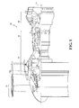
- FIG. 1 schematically illustrates a gas turbine engine 20.
- the gas turbine engine 20 is disclosed herein as a two-spool turbofan that generally incorporates a fan section 22, a compressor section 24, a combustor section 26 and a turbine section 28.
- the fan section 22 drives air along a bypass flowpath while the compressor section 24 drives air along a core flowpath for compression and communication into the combustor section 26 then expansion through the turbine section 28.
- turbofan Although depicted as a turbofan in the disclosed non-limiting embodiment, it should be understood that the concepts described herein are not limited to use with turbofans as the teachings may be applied to other types of turbomachinery to include, but not be limited to, low bypass augmented turbofans, turbojets, turboshafts, three-spool (plus fan) turbofans and industrial gas turbines.
- a process 100 according to one disclosed non-limiting embodiment for application of a coating system 40 to a component 42 ( Figure 3 ) subjected to high temperatures is schematically represented.
- the steps of the process 100 are schematically disclosed in terms of functional block diagrams as a flowchart. It should be appreciated that alternative of addition steps may be provided without departing from the teaching herein.
- Representative examples of the component 42 include but are not limited to combustor section 26 and/or turbine section 28 hardware such as augmentor components, combustor liners, blades, vanes, and blade outer air seals.
- the coating system 40 as described herein is suitable for protection of a substrate 42 such as a superalloy but while being described with reference to such superalloy gas turbine engine components, the teachings herein are generally applicable to any component on which a Thermal Barrier Coating (TBC) may be used to protect the component from a high temperature environment, particularly environments containing CMAS.
- TBC Thermal Barrier Coating
- the coating system 40 in one disclosed non-limiting embodiment is manufactured by the process 100 which initially includes application of a bond coat 44 on the substrate 42 (step 102 and Figure 3 ).
- the bond coat 44 may include an aluminum-rich composition, such as an overlay coating or a diffusion coating such as a diffusion aluminide or a diffusion platinum aluminide according to formulas such as MCrAlY, MCrAlY +Hf, and MCrAlY + HF+Si, in which M denotes nickel, cobalt, iron, platinum or mixtures thereof; Cr denotes chromium; Al denotes aluminum; and Y denotes yttrium.
- MCrAlY materials are often referred to as overlay coatings because they are applied in a predetermined composition and do not interact significantly with the substrate 42 during the deposition process.
- One example preferred MCrAlY bond coat composition has a weight percent compositional range of 5-40 Cr, 8-35 Al, 0.1-2.0 Y, 0.1-7 Si, 0.1-2.0 Hf, balance selected from the group consisting of Ni, Co and mixtures thereof.
- the bond coat material may include Al, PtAl and the like, that are often referred to as diffusion coatings.
- the bond coat material may also include Al, PtAl, MCrAlY as described above, and the like, that are often referred to as cathodic arc coatings.
- the bond coat 44 may be applied by any method operable to produce a dense, uniform, adherent coating of the desired composition, such as, but not limited to, an overlay bond coat, diffusion bond coat, cathodic arc bond coat, etc.
- Such techniques may include, but are not limited to, diffusion processes (e.g., inward, outward, etc.), low pressure plasma-spray, air plasma-spray, sputtering, cathodic arc, electron beam physical vapor deposition, high velocity plasma spray techniques (e.g., HVOF, HVAF), combustion processes, wire spray techniques, laser beam cladding, electron beam cladding, etc.
- the particle size for the bond coat 44 may be of any suitable size, and in may be between about 15 microns (0.015 mm) and about 60 microns (0.060 mm) with a mean particle size of about 25 microns (0.025 mm).
- the bond coat 44 may be applied to any suitable thickness, and may be about 5 mils (0.127 mm) to about 10 mils (0.254 mm) thick. In some embodiments, the thickness may be about 6 mils (0.152 mm) to about 7 mils (0.178 mm) thick.
- a thermal barrier coating material 48 ( Figure 3 ), often referred to as a top coat, may be applied to the bond coat 44 (step 104).
- the thermal barrier coating material 48 may include a ceramic based compound.
- Representative thermal barrier coating materials include, but are not limited to: a stabilized zirconate, a stabilized hafnate, combinations including at least one of the foregoing compounds, and the like, for example, yttria stabilized zirconia, calcia stabilized zirconia, magnesia stabilized zirconia, yttria stabilized hafnia, calcia stabilized hafnia and magnesia stabilized hafnia.
- Yttria stabilized zirconia is commercially available as 7YSZ.
- One example preferred thermal barrier coating material 48 is a zirconia stabilized by between 6-8wt% yttria that is about 0.05-5 mil (0.00127 - 0.127 mm) in thickness deposited, nominally at 1-3 mil (0.0254- 0.0761 mm).
- the thermal barrier coating material 48 may be applied by various known methods. Suitable application methods include, but are not limited to, physical vapor deposition (e.g., electron beam), thermal spray (e.g., air plasma, high velocity oxygen fuel), sputtering, sol gel, slurry, combinations comprising at least one of the foregoing application processes, and the like.
- physical vapor deposition e.g., electron beam
- thermal spray e.g., air plasma, high velocity oxygen fuel
- sputtering e.g., sol gel, slurry, combinations comprising at least one of the foregoing application processes, and the like.
- a blocking material 50 is selectively infiltrated into the thermal barrier coating material 48 to form an exposed surface 60 (step 106; Figure 2 ).
- the blocking material 50 includes a filler material 52 within a carrier 54.
- the blocking material 50 include, but are not limited to, filled or unfilled pre-ceramic polymer resins, filled sacrificial polymer resin carriers, or combinations thereof.
- the filler materials 52 include, but are not limited to, pre-reacted volcanic ash powder, calcium magnesium alumino silicate (CMAS), other environmental contaminants, such as vanadates and sulfur compounds, ceramic nano-particles, and other particles ranging from 0.1-10 um, and metal organic compounds within a carrier 54 such as a polymer resin, ethanol, jet fuel, and water that forms a solution, suspension, or colloid.
- a carrier 54 such as a polymer resin, ethanol, jet fuel, and water that forms a solution, suspension, or colloid.
- the polymer resin operates as a jet fuel or water carrier and the filler may be the same materials listed.
- the ceramic precursor polymers are capable of conversion to a ceramic upon sufficient heat treatment as well as conversion to a phase such as a rare-earth silicate.
- blocking material 50 into a porous solid form would include, but are not limited to, vacuum, temperature, and pressure assisted processes that may improve the natural filling obtained by capillary forces.
- a common embodiment of such a process could involve dipping or submerging a porous system 40 in a bath of polymer resin allowing infiltration into the structure. Controlling the exposure time and the temperature of the process could enable selective infiltration to partial depths. This process would then be followed by appropriate heat treatments to enable the conversion of the system to the desired phase.
- An alternative deposition methodology for the blocking material 50 includes Suspension Plasma Spray (SPS) or Suspension Precursor Plasma Spray (SPPS) which facilitate a wide range of chemistries and microstructures to simultaneously optimize cost and strain tolerance.
- SPS is a form of plasma spraying where the ceramic feedstock is dispersed in a liquid suspension before being injected into the plasma jet which facilities deposition of finer microstructures through the use of finer powders.
- SPPS is a solution based process by which a solution of soluble metal cations is injected into a plasma plume.
- the source material for the blocking material 50 may be provided as sub-micron particles dispersed in alcohol, water, or another suitable carrier.
- the source material for the blocking material 50 may be provided as metal salts or metal-organic compounds that would be dispersed in alcohol, water, or other suitable carrier, i.e., Calcium Nitrate + Tetra-ethyl-ortho-silicate + rare earth nitrate in an alcohol solution.
- the carrier 54 of the blocking material 50 is then removed (step 108) to form a second phase that alters the thermal barrier coating material 48 with an essentially pre-sealed structure.
- the blocking material 50 is infiltrated into the thermal barrier coating material 48 to a depth of, for example, about 10 microns (0.39 mil; 0.01mm).
- the carrier 54 can be removed via, for example, an engine "green run” heat treat procedure, to react the materials to form the desirable stable, high temperature, ceramic phase such as a rare-earth apatite. That is, the carrier 54 can be removed during manufacture and/or initial testing operations, i.e., "green run” that is typical of gas turbine engine initial operations.
- the process 100 provides for selective infiltration, into the thermal barrier coating material 48 to form multi-phase material layer coating system 40.
- the coating system 40 forms a multi-phase pre-reacted surficial region, to mitigate or completely eliminate damage to thermal barrier coating material 48 by CMAS or other contaminants on hot section gas turbine engine components.
- altered thermal barrier coating material 48 Potential uses of the altered thermal barrier coating material 48 include, but are not limited to, improving the environmental contaminant resistance of altered thermal barrier coating material 48 coated components through the formation of the multi-phase pre-reacted surficial region, subsequently improving the temperature capability of the altered thermal barrier coating material 48, and evaluating the mechanical properties of potentially compromised (contaminated) altered thermal barrier coating material 48 structures.
Landscapes
- Chemical & Material Sciences (AREA)
- Engineering & Computer Science (AREA)
- Mechanical Engineering (AREA)
- Materials Engineering (AREA)
- Organic Chemistry (AREA)
- Chemical Kinetics & Catalysis (AREA)
- Metallurgy (AREA)
- Physics & Mathematics (AREA)
- Plasma & Fusion (AREA)
- Inorganic Chemistry (AREA)
- General Engineering & Computer Science (AREA)
- Ceramic Engineering (AREA)
- Turbine Rotor Nozzle Sealing (AREA)
- Coating By Spraying Or Casting (AREA)
Abstract
Description
- The present disclosure relates to thermal barrier coating (TBC) compositions designed to withstand infiltration from molten environmental contaminant infiltration, processes for applying same, and components coated with same.
- Gas turbine engines typically include a compressor to pressurize airflow, a combustor to burn a hydrocarbon fuel in the presence of the pressurized air, and a turbine to extract energy from the resultant combustion gases. The combustor and the turbine form the hot section of the engine and components therein often include a thermal barrier coating.
- Thermal insulation provided by the TBC enables hot section components to survive higher operating temperatures and can increase both component and engine durability. The TBC is typically a refractory ceramic material deposited on a bond coat to form what may be termed a TBC system. Bond coat materials widely used in TBC systems include oxidation-resistant overlay coatings such as MCrAlX (where M is iron, cobalt and/or nickel, X is yttrium or another rare earth element, and Hf, Si or other transition metal elements can be added as minor constituents), and diffusion coatings such as diffusion aluminides that contain aluminum intermetallics.
- Ceramic materials and particularly binary yttria-stabilized zirconia (YSZ) are widely used as TBC materials because of their high temperature capability, low thermal conductivity, and relative ease of deposition such as by air plasma spraying (APS), flame spraying such as high-velocity oxy-fuel (HVOF), physical vapor deposition (PVD) and other techniques.
- Under service conditions, these TBC coated hot section engine components can be susceptible to various modes of damage, including erosion, oxidation and corrosion from exposure to the gaseous products of combustion, foreign object damage and attack from environmental contaminants. Contaminants including Calcium Magnesium Alumino-Silicate (CMAS), Volcanic Ash, Fly Ash, and others can adhere to the TBC surfaces of the hot section components. CMAS particulate is often contained in the atmosphere as fine sand and/or dust. The interaction between the TBC and contaminants may result in premature TBC loss over the life of the components.
- CMAS infiltration is a phenomenon that is linked to premature TBC spallation. CMAS may melt on the hot section components during the turbine operation and penetrate the strain tolerant porosity of the TBC microstructure. Upon cooling, this penetrated layer stiffens and the induced strain energy can lead to premature TBC spallation.
- Rare earth zirconates are often utilized to react with the encroaching CMAS melt which may decrease the depth and rate of infiltration of the melt and hence the strain energy introduced into the coating to delay premature coating spallation. However, formation of this reaction layer is not readily controllable in service, as a number of extrinsic factors such as CMAS deposition rate, surface temperatures, airflow, erosion of the TBC, and foreign object damage may result in variation in penetration depth and the potential resultant damage.
- Some alternative coating chemistries based on the Lanthanide series rare earth oxides (La (57) to Lu (71)) such as gadolinium zirconate (GdZr) can form an apatite phase when exposed to certain environmental contaminants. A high temperature apatite phase is capable of reducing the rate of degradation of the TBC in service compared to other coatings such as yittria-stabilized zirconica (YSZ). The development of mechanical property tests (such as modulus, flexural strength, etc.) to evaluate the behavior of TBCs when attacked by environmental contaminants has been limited by the inability to infiltrate the actual environmental contaminants into the system without causing premature spallation of the TBC.
- Conventional processes using environmental contaminant chemicals have been primarily focused on the addition of chemicals in a powder or liquid form. The thermal processing required to infiltrate the TBC involves temperatures greater than 2150°F (1177 °C) to fully infiltrate the TBC for testing purposes. When cooled from an isothermal hold at these temperatures, the TBC can experience spallation, including complete separation from the metallic substrate, due to the relatively large mismatch between the coefficients of thermal expansion between the ceramic top coat and the underlying substrate and the lower toughness of the ceramic top coat.
- A process for coating a component according to one disclosed non-limiting embodiment of the present disclosure includes selectively infiltrating a blocking material into the thermal barrier coating material.
- A further embodiment of the present disclosure includes a process, wherein the blocking material is infiltrated into the thermal barrier coating material to a depth less than 50 microns.
- A further embodiment of any of the foregoing embodiments of the present disclosure includes removing a carrier of the blocking material.
- A further embodiment of any of the foregoing embodiments of the present disclosure includes, wherein removing the carrier of the blocking material is effectuated via a "green run" that is typical of gas turbine engine initial runs.
- A further embodiment of any of the foregoing embodiments of the present disclosure includes, wherein removing the carrier of the blocking material is effectuated via a heat treat process.
- A further embodiment of any of the foregoing embodiments of the present disclosure includes, wherein removing the carrier of the blocking material is effectuated during the formation of high temperature silicates such as a rare-earth apatite phase.
- A further embodiment of any of the foregoing embodiments of the present disclosure includes, wherein the blocking material is formed via one of Suspension Plasma Spray (SPS) and Suspension Precursor Plasma Spray (SPPS) to form the exposed surface.
- A further embodiment of any of the foregoing embodiments of the present disclosure includes, wherein the blocking material is a filled pre-ceramic polymer resin.
- A further embodiment of any of the foregoing embodiments of the present disclosure includes, wherein the blocking material is an unfilled pre-ceramic polymer resin.
- A further embodiment of any of the foregoing embodiments of the present disclosure includes, wherein selectively infiltrating a blocking material into the thermal barrier coating material forms a multi-phase pre-reacted surficial region.
- A further embodiment of any of the foregoing embodiments of the present disclosure includes, wherein the blocking material is a filled sacrificial polymer resin carrier.
- A further embodiment of any of the foregoing embodiments of the present disclosure includes, wherein the blocking material includes a filler material and a carrier.
- A further embodiment of any of the foregoing embodiments of the present disclosure includes, wherein the filling material is a volcanic ash powder.
- A further embodiment of any of the foregoing embodiments of the present disclosure includes, wherein the filling material is a calcium magnesium alumino silicate (CMAS) based compound.
- A further embodiment of any of the foregoing embodiments of the present disclosure includes, wherein the carrier is one of ethanol, jet fuel, polymer resin, and water.
- A process for coating a component according to another disclosed non-limiting embodiment of the present disclosure includes selectively infiltrating a blocking material including carrier, and which may include a filler, into a thermal barrier coating material; and removing the carrier.
- A further embodiment of any of the foregoing embodiments of the present disclosure includes, wherein the blocking material is infiltrated into the thermal barrier coating material to a depth of less than about 50 microns.
- A gas turbine engine component according to another disclosed non-limiting embodiment of the present disclosure includes a superalloy substrate; a bond coat on the substrate; a thermal barrier coating material on the bond coat; and a blocking material infiltrated into the thermal barrier coating material to a depth up to about 10 microns.
- A further embodiment of any of the foregoing embodiments of the present disclosure includes, wherein the blocking material includes at least one of a filled pre-ceramic polymer resin, an unfilled pre-ceramic polymer resin, and a filled sacrificial polymer resin carrier.
- A further embodiment of any of the foregoing embodiments of the present disclosure includes, wherein the blocking material includes a carrier of at least one of, ethanol, jet fuel, polymer resin, and water.
- The foregoing features and elements may be combined in various combinations without exclusivity, unless expressly indicated otherwise. These features and elements as well as the operation thereof will become more apparent in light of the following description and the accompanying drawings. It should be understood, however, the following description and drawings are intended to be exemplary in nature and non-limiting.
- Various features will become apparent to those skilled in the art from the following detailed description of the disclosed non-limiting embodiment. The drawings that accompany the detailed description can be briefly described as follows:
-
Figure 1 is a schematic cross-section of an example gas turbine engine architecture; -
Figure 2 is a flowchart of a process according to one disclosed non-limiting embodiment for application of a coating system to a component; and -
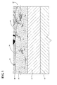
Figure 3 is a cross-section through the coating system applied in accordance with the process ofFigure 2 . -
Figure 1 schematically illustrates agas turbine engine 20. Thegas turbine engine 20 is disclosed herein as a two-spool turbofan that generally incorporates a fan section 22, acompressor section 24, acombustor section 26 and aturbine section 28. The fan section 22 drives air along a bypass flowpath while thecompressor section 24 drives air along a core flowpath for compression and communication into thecombustor section 26 then expansion through theturbine section 28. Although depicted as a turbofan in the disclosed non-limiting embodiment, it should be understood that the concepts described herein are not limited to use with turbofans as the teachings may be applied to other types of turbomachinery to include, but not be limited to, low bypass augmented turbofans, turbojets, turboshafts, three-spool (plus fan) turbofans and industrial gas turbines. - With reference to
Figure 2 , aprocess 100 according to one disclosed non-limiting embodiment for application of acoating system 40 to a component 42 (Figure 3 ) subjected to high temperatures is schematically represented. The steps of theprocess 100 are schematically disclosed in terms of functional block diagrams as a flowchart. It should be appreciated that alternative of addition steps may be provided without departing from the teaching herein. - Representative examples of the
component 42 include but are not limited tocombustor section 26 and/orturbine section 28 hardware such as augmentor components, combustor liners, blades, vanes, and blade outer air seals. Thecoating system 40 as described herein is suitable for protection of asubstrate 42 such as a superalloy but while being described with reference to such superalloy gas turbine engine components, the teachings herein are generally applicable to any component on which a Thermal Barrier Coating (TBC) may be used to protect the component from a high temperature environment, particularly environments containing CMAS. - The
coating system 40, in one disclosed non-limiting embodiment is manufactured by theprocess 100 which initially includes application of abond coat 44 on the substrate 42 (step 102 andFigure 3 ). Thebond coat 44 may include an aluminum-rich composition, such as an overlay coating or a diffusion coating such as a diffusion aluminide or a diffusion platinum aluminide according to formulas such as MCrAlY, MCrAlY +Hf, and MCrAlY + HF+Si, in which M denotes nickel, cobalt, iron, platinum or mixtures thereof; Cr denotes chromium; Al denotes aluminum; and Y denotes yttrium. MCrAlY materials are often referred to as overlay coatings because they are applied in a predetermined composition and do not interact significantly with thesubstrate 42 during the deposition process. One example preferred MCrAlY bond coat composition has a weight percent compositional range of 5-40 Cr, 8-35 Al, 0.1-2.0 Y, 0.1-7 Si, 0.1-2.0 Hf, balance selected from the group consisting of Ni, Co and mixtures thereof. Alternatively or in addition the bond coat material may include Al, PtAl and the like, that are often referred to as diffusion coatings. Alternatively or in addition, the bond coat material may also include Al, PtAl, MCrAlY as described above, and the like, that are often referred to as cathodic arc coatings. - The
bond coat 44 may be applied by any method operable to produce a dense, uniform, adherent coating of the desired composition, such as, but not limited to, an overlay bond coat, diffusion bond coat, cathodic arc bond coat, etc. Such techniques may include, but are not limited to, diffusion processes (e.g., inward, outward, etc.), low pressure plasma-spray, air plasma-spray, sputtering, cathodic arc, electron beam physical vapor deposition, high velocity plasma spray techniques (e.g., HVOF, HVAF), combustion processes, wire spray techniques, laser beam cladding, electron beam cladding, etc. - The particle size for the
bond coat 44 may be of any suitable size, and in may be between about 15 microns (0.015 mm) and about 60 microns (0.060 mm) with a mean particle size of about 25 microns (0.025 mm). Thebond coat 44 may be applied to any suitable thickness, and may be about 5 mils (0.127 mm) to about 10 mils (0.254 mm) thick. In some embodiments, the thickness may be about 6 mils (0.152 mm) to about 7 mils (0.178 mm) thick. - Next, a thermal barrier coating material 48 (
Figure 3 ), often referred to as a top coat, may be applied to the bond coat 44 (step 104). The thermalbarrier coating material 48 may include a ceramic based compound. Representative thermal barrier coating materials include, but are not limited to: a stabilized zirconate, a stabilized hafnate, combinations including at least one of the foregoing compounds, and the like, for example, yttria stabilized zirconia, calcia stabilized zirconia, magnesia stabilized zirconia, yttria stabilized hafnia, calcia stabilized hafnia and magnesia stabilized hafnia. Yttria stabilized zirconia is commercially available as 7YSZ. One example preferred thermalbarrier coating material 48 is a zirconia stabilized by between 6-8wt% yttria that is about 0.05-5 mil (0.00127 - 0.127 mm) in thickness deposited, nominally at 1-3 mil (0.0254- 0.0761 mm). - The thermal
barrier coating material 48 may be applied by various known methods. Suitable application methods include, but are not limited to, physical vapor deposition (e.g., electron beam), thermal spray (e.g., air plasma, high velocity oxygen fuel), sputtering, sol gel, slurry, combinations comprising at least one of the foregoing application processes, and the like. - Next, a blocking
material 50 is selectively infiltrated into the thermalbarrier coating material 48 to form an exposed surface 60 (step 106;Figure 2 ). In one disclosed non-limiting embodiment, the blockingmaterial 50 includes afiller material 52 within acarrier 54. Examples of the blockingmaterial 50 include, but are not limited to, filled or unfilled pre-ceramic polymer resins, filled sacrificial polymer resin carriers, or combinations thereof. Examples of thefiller materials 52 include, but are not limited to, pre-reacted volcanic ash powder, calcium magnesium alumino silicate (CMAS), other environmental contaminants, such as vanadates and sulfur compounds, ceramic nano-particles, and other particles ranging from 0.1-10 um, and metal organic compounds within acarrier 54 such as a polymer resin, ethanol, jet fuel, and water that forms a solution, suspension, or colloid. For example, the polymer resin operates as a jet fuel or water carrier and the filler may be the same materials listed. The ceramic precursor polymers are capable of conversion to a ceramic upon sufficient heat treatment as well as conversion to a phase such as a rare-earth silicate. - Common methodologies for infiltrating a polymeric based, pre-ceramic or otherwise, blocking
material 50 into a porous solid form would include, but are not limited to, vacuum, temperature, and pressure assisted processes that may improve the natural filling obtained by capillary forces. A common embodiment of such a process could involve dipping or submerging aporous system 40 in a bath of polymer resin allowing infiltration into the structure. Controlling the exposure time and the temperature of the process could enable selective infiltration to partial depths. This process would then be followed by appropriate heat treatments to enable the conversion of the system to the desired phase. - An alternative deposition methodology for the blocking
material 50 includes Suspension Plasma Spray (SPS) or Suspension Precursor Plasma Spray (SPPS) which facilitate a wide range of chemistries and microstructures to simultaneously optimize cost and strain tolerance. SPS is a form of plasma spraying where the ceramic feedstock is dispersed in a liquid suspension before being injected into the plasma jet which facilities deposition of finer microstructures through the use of finer powders. SPPS is a solution based process by which a solution of soluble metal cations is injected into a plasma plume. For SPS, the source material for the blockingmaterial 50 may be provided as sub-micron particles dispersed in alcohol, water, or another suitable carrier. For SPPS the source material for the blockingmaterial 50 may be provided as metal salts or metal-organic compounds that would be dispersed in alcohol, water, or other suitable carrier, i.e., Calcium Nitrate + Tetra-ethyl-ortho-silicate + rare earth nitrate in an alcohol solution. - The
carrier 54 of the blockingmaterial 50 is then removed (step 108) to form a second phase that alters the thermalbarrier coating material 48 with an essentially pre-sealed structure. The blockingmaterial 50 is infiltrated into the thermalbarrier coating material 48 to a depth of, for example, about 10 microns (0.39 mil; 0.01mm). Thecarrier 54 can be removed via, for example, an engine "green run" heat treat procedure, to react the materials to form the desirable stable, high temperature, ceramic phase such as a rare-earth apatite. That is, thecarrier 54 can be removed during manufacture and/or initial testing operations, i.e., "green run" that is typical of gas turbine engine initial operations. - The
process 100 provides for selective infiltration, into the thermalbarrier coating material 48 to form multi-phase materiallayer coating system 40. Thecoating system 40 forms a multi-phase pre-reacted surficial region, to mitigate or completely eliminate damage to thermalbarrier coating material 48 by CMAS or other contaminants on hot section gas turbine engine components. - Potential uses of the altered thermal
barrier coating material 48 include, but are not limited to, improving the environmental contaminant resistance of altered thermalbarrier coating material 48 coated components through the formation of the multi-phase pre-reacted surficial region, subsequently improving the temperature capability of the altered thermalbarrier coating material 48, and evaluating the mechanical properties of potentially compromised (contaminated) altered thermalbarrier coating material 48 structures. - The modifications of the material proposed should not be limited to altered thermal
barrier coating material 48 and may be applicable to any porous ceramic or metallic material for the above described purposes, among others. - The use of the terms "a" and "an" and "the" and similar references in the context of description (especially in the context of the following claims) are to be construed to cover both the singular and the plural, unless otherwise indicated herein or specifically contradicted by context. The modifier "about" used in connection with a quantity is inclusive of the stated value and has the meaning dictated by the context (e.g., it includes the degree of error associated with measurement of the particular quantity). All ranges disclosed herein are inclusive of the endpoints, and the endpoints are independently combinable with each other. It should be appreciated that relative positional terms such as "forward," "aft," "upper," "lower," "above," "below," and the like are with reference to the normal operational attitude of the vehicle and should not be considered otherwise limiting.
- Although the different non-limiting embodiments have specific illustrated components, the embodiments of this invention are not limited to those particular combinations. It is possible to use some of the components or features from any of the non-limiting embodiments in combination with features or components from any of the other non-limiting embodiments.
- It should be appreciated that like reference numerals identify corresponding or similar elements throughout the several drawings. It should also be appreciated that although a particular component arrangement is disclosed in the illustrated embodiment, other arrangements will benefit herefrom.
- Although particular step sequences are shown, described, and claimed, it should be understood that steps may be performed in any order, repeated any number of times, separated or combined unless otherwise indicated and will still benefit from the present disclosure.
- The foregoing description is exemplary rather than defined by the limitations within. Various non-limiting embodiments are disclosed herein, however, one of ordinary skill in the art would recognize that various modifications and variations in light of the above teachings will fall within the scope of the appended claims. It is therefore to be understood that within the scope of the appended claims, the disclosure may be practiced other than as specifically described. For that reason the appended claims should be studied to determine true scope and content.
Claims (15)
- A process for coating a component (42), comprising:applying a bond coat (44) on a substrate (42) of the component (42);applying a thermal barrier coating material (48) to the bond coat (44); andselectively infiltrating a blocking material (50) into the thermal barrier coating material (48).
- The process as recited in claim 1, further comprising removing a carrier (54) of the blocking material (50).
- The process as recited in claim 2, wherein removing the carrier (54) of the blocking material (50) is effectuated via a "green run."
- The process as recited in claim 2 or 3, wherein removing the carrier (54) of the blocking material (50) is effectuated via a heat treat process.
- The process as recited in claim 2, 3 or 4, wherein removing the carrier (54) of the blocking material (50) is effectuated during the formation of high temperature rare-earth silicate phases, such as apatite.
- The process as recited in any preceding claim, wherein the blocking material (50) is formed via one of Suspension Plasma Spray (SPS) and Suspension Precursor Plasma Spray (SPPS) to form an exposed surface (60).
- The process as recited in any preceding claim, wherein selectively infiltrating a blocking material (50) into the thermal barrier coating material (48) forms a multi-phase pre-reacted surficial region.
- The process as recited in any preceding claim, wherein the blocking material (50) includes a filler material (52) and a/the carrier (54).
- The process as recited in claim 8, wherein the filling material (52) is a pre-reacted volcanic ash powder.
- The process as recited in claim 8, wherein the filling material (52) is a calcium magnesium alumino silicate (CMAS) based compound.
- A process for coating a component (42), comprising:selectively infiltrating a blocking material (50) including a filler material (52) and a carrier (54) into a thermal barrier coating material (48); andremoving the carrier material (54).
- The process as recited in any preceding claim, wherein the blocking material (50) is infiltrated into the thermal barrier coating material (48) to a depth of less than 50 microns.
- A gas turbine engine component (42), comprising:a superalloy substrate (42);a bond coat (44) on the substrate (42);a thermal barrier coating material (50) on the bond coat (44); anda blocking material (50) infiltrated into the thermal barrier coating material (50) to a depth of less than 50 microns.
- The process or component (42) as recited in any preceding claim, wherein the blocking material (50) includes at least one of a filled or unfilled pre-ceramic polymer resin, and a filled sacrificial polymer resin carrier (54).
- The process or component (42) as recited in any preceding claim, wherein the blocking material (50) includes a/the carrier and the carrier (54) is at least one of, ethanol, jet fuel, polymer resin, and water.
Applications Claiming Priority (1)
| Application Number | Priority Date | Filing Date | Title |
|---|---|---|---|
| US201462058047P | 2014-09-30 | 2014-09-30 |
Publications (2)
| Publication Number | Publication Date |
|---|---|
| EP3002348A1 true EP3002348A1 (en) | 2016-04-06 |
| EP3002348B1 EP3002348B1 (en) | 2019-12-04 |
Family
ID=54251386
Family Applications (1)
| Application Number | Title | Priority Date | Filing Date |
|---|---|---|---|
| EP15187651.3A Active EP3002348B1 (en) | 2014-09-30 | 2015-09-30 | Process for coating gas turbine engine components comprising multi-phase pre-reacted thermal barrier coatings and coated gas turbine engine components |
Country Status (2)
| Country | Link |
|---|---|
| US (1) | US20160362775A1 (en) |
| EP (1) | EP3002348B1 (en) |
Families Citing this family (6)
| Publication number | Priority date | Publication date | Assignee | Title |
|---|---|---|---|---|
| US10196983B2 (en) * | 2015-11-04 | 2019-02-05 | General Electric Company | Fuel nozzle for gas turbine engine |
| US10508809B2 (en) * | 2016-10-31 | 2019-12-17 | General Electric Company | Articles for high temperature service and methods for making |
| FR3067391B1 (en) | 2017-06-12 | 2020-12-04 | Safran | REINFORCED ANTI-CMAS COATING |
| FR3067392B1 (en) * | 2017-06-12 | 2020-12-04 | Safran | DOUBLE REACTIVITY ANTI-CMAS COATING |
| US11773734B2 (en) * | 2017-09-07 | 2023-10-03 | General Electric Company | Liquid bond coatings for barrier coatings |
| EP3957827B1 (en) | 2020-08-18 | 2024-10-02 | Ansaldo Energia Switzerland AG | A coating system for a component of a gas turbine engine |
Citations (6)
| Publication number | Priority date | Publication date | Assignee | Title |
|---|---|---|---|---|
| EP1428902A1 (en) * | 2002-12-12 | 2004-06-16 | General Electric Company | Thermal barrier coating protected by infiltrated alumina and method for preparing same |
| EP1806431A2 (en) * | 2006-01-10 | 2007-07-11 | United Technologies Corporation | Thermal barrier coating compositions, processes for applying same and articles coated with same |
| EP1806423A1 (en) * | 2006-01-10 | 2007-07-11 | United Technologies Corporation | Thermal barrier coating compositions, processes for applying same and articles coated with same |
| EP2233600A1 (en) * | 2009-03-26 | 2010-09-29 | Alstom Technology Ltd | Method for the protection of a thermal barrier coating system and a method for the renewal of such a protection |
| US20140065408A1 (en) * | 2012-09-05 | 2014-03-06 | Christopher W. Strock | Thermal barrier coating for gas turbine engine components |
| EP2766504A2 (en) * | 2011-10-13 | 2014-08-20 | General Electric Company | Thermal barrier coating systems and processes therefor |
Family Cites Families (6)
| Publication number | Priority date | Publication date | Assignee | Title |
|---|---|---|---|---|
| US5293775A (en) * | 1992-11-02 | 1994-03-15 | United Technologies Corporation | Gas turbine engine test cell |
| JP2009536982A (en) * | 2006-01-25 | 2009-10-22 | セラマテック・インク | Environmental and thermal barrier coatings to protect pre-coated substrates |
| US9322089B2 (en) * | 2006-06-02 | 2016-04-26 | Alstom Technology Ltd | Nickel-base alloy for gas turbine applications |
| US7619728B2 (en) * | 2007-07-26 | 2009-11-17 | General Electric Company | Methods and systems for in-situ machinery inspection |
| US20100154422A1 (en) * | 2008-12-19 | 2010-06-24 | Glen Harold Kirby | Cmas mitigation compositions, environmental barrier coatings comprising the same, and ceramic components comprising the same |
| US20120034491A1 (en) * | 2010-08-05 | 2012-02-09 | United Technologies Corporation | Cmas resistant tbc coating |
-
2015
- 2015-09-25 US US14/865,038 patent/US20160362775A1/en active Pending
- 2015-09-30 EP EP15187651.3A patent/EP3002348B1/en active Active
Patent Citations (6)
| Publication number | Priority date | Publication date | Assignee | Title |
|---|---|---|---|---|
| EP1428902A1 (en) * | 2002-12-12 | 2004-06-16 | General Electric Company | Thermal barrier coating protected by infiltrated alumina and method for preparing same |
| EP1806431A2 (en) * | 2006-01-10 | 2007-07-11 | United Technologies Corporation | Thermal barrier coating compositions, processes for applying same and articles coated with same |
| EP1806423A1 (en) * | 2006-01-10 | 2007-07-11 | United Technologies Corporation | Thermal barrier coating compositions, processes for applying same and articles coated with same |
| EP2233600A1 (en) * | 2009-03-26 | 2010-09-29 | Alstom Technology Ltd | Method for the protection of a thermal barrier coating system and a method for the renewal of such a protection |
| EP2766504A2 (en) * | 2011-10-13 | 2014-08-20 | General Electric Company | Thermal barrier coating systems and processes therefor |
| US20140065408A1 (en) * | 2012-09-05 | 2014-03-06 | Christopher W. Strock | Thermal barrier coating for gas turbine engine components |
Also Published As
| Publication number | Publication date |
|---|---|
| US20160362775A1 (en) | 2016-12-15 |
| EP3002348B1 (en) | 2019-12-04 |
Similar Documents
| Publication | Publication Date | Title |
|---|---|---|
| EP2947173B1 (en) | Calcium magnesium aluminosilicate (cmas) resistant thermal barrier coating and coating process therefor | |
| US7374825B2 (en) | Protection of thermal barrier coating by an impermeable barrier coating | |
| US9023486B2 (en) | Thermal barrier coating systems and processes therefor | |
| EP1806436B1 (en) | Thermal barrier coating compositions, processes for applying same and articles coated with same | |
| EP2053141B1 (en) | Alumina-based protective coating for thermal barrier coatings and process for depositing thereof | |
| EP1666633B1 (en) | Protection of a thermal barrier coating by a sacrificial coating | |
| JP3579267B2 (en) | Method for densifying bond coat for thermal barrier coating system and promoting bonding between particles | |
| EP3002348B1 (en) | Process for coating gas turbine engine components comprising multi-phase pre-reacted thermal barrier coatings and coated gas turbine engine components | |
| US7807231B2 (en) | Process for forming thermal barrier coating resistant to infiltration | |
| EP1806431A2 (en) | Thermal barrier coating compositions, processes for applying same and articles coated with same | |
| US11549382B2 (en) | Restoration coating system and method | |
| US20230228199A1 (en) | Slotted ceramic coating with a reactive phase coating disposed thereon for improved cmas resistance and methods of forming the same | |
| JP2006347870A (en) | Process for producing corrosion-resistant EBC bond coats and the like for silicon-containing substrates | |
| CA2695850A1 (en) | Thermal barrier coating with lower thermal conductivity | |
| US20150247245A1 (en) | Protective coating systems for gas turbine engine applications and methods for fabricating the same | |
| US10364701B2 (en) | CMAS barrier coating for a gas turbine engine having a reactive material that reacts with a layer of environmental contaminant compositions and method of applying the same | |
| JP2010043351A (en) | Thermal barrier coating and method for production thereof | |
| EP1686199A2 (en) | Thermal barrier coating system and process therefor | |
| EP2423347A1 (en) | Method for forming a thermal barrier coating and a turbine component with the thermal barrier coating |
Legal Events
| Date | Code | Title | Description |
|---|---|---|---|
| PUAI | Public reference made under article 153(3) epc to a published international application that has entered the european phase |
Free format text: ORIGINAL CODE: 0009012 |
|
| AK | Designated contracting states |
Kind code of ref document: A1 Designated state(s): AL AT BE BG CH CY CZ DE DK EE ES FI FR GB GR HR HU IE IS IT LI LT LU LV MC MK MT NL NO PL PT RO RS SE SI SK SM TR |
|
| AX | Request for extension of the european patent |
Extension state: BA ME |
|
| RAP1 | Party data changed (applicant data changed or rights of an application transferred) |
Owner name: UNITED TECHNOLOGIES CORPORATION |
|
| 17P | Request for examination filed |
Effective date: 20161006 |
|
| RBV | Designated contracting states (corrected) |
Designated state(s): AL AT BE BG CH CY CZ DE DK EE ES FI FR GB GR HR HU IE IS IT LI LT LU LV MC MK MT NL NO PL PT RO RS SE SI SK SM TR |
|
| STAA | Information on the status of an ep patent application or granted ep patent |
Free format text: STATUS: EXAMINATION IS IN PROGRESS |
|
| 17Q | First examination report despatched |
Effective date: 20170321 |
|
| REG | Reference to a national code |
Ref country code: DE Ref legal event code: R079 Ref document number: 602015042845 Country of ref document: DE Free format text: PREVIOUS MAIN CLASS: C23C0028000000 Ipc: C23C0004020000 |
|
| GRAP | Despatch of communication of intention to grant a patent |
Free format text: ORIGINAL CODE: EPIDOSNIGR1 |
|
| STAA | Information on the status of an ep patent application or granted ep patent |
Free format text: STATUS: GRANT OF PATENT IS INTENDED |
|
| RIC1 | Information provided on ipc code assigned before grant |
Ipc: C23C 4/02 20060101AFI20190516BHEP Ipc: C23C 28/00 20060101ALI20190516BHEP Ipc: C23C 4/134 20160101ALI20190516BHEP Ipc: C23C 28/04 20060101ALI20190516BHEP Ipc: F01D 5/28 20060101ALI20190516BHEP Ipc: C23C 4/18 20060101ALI20190516BHEP Ipc: C23C 4/11 20160101ALI20190516BHEP Ipc: F01D 25/00 20060101ALI20190516BHEP Ipc: C23C 4/10 20160101ALI20190516BHEP |
|
| INTG | Intention to grant announced |
Effective date: 20190614 |
|
| GRAS | Grant fee paid |
Free format text: ORIGINAL CODE: EPIDOSNIGR3 |
|
| GRAA | (expected) grant |
Free format text: ORIGINAL CODE: 0009210 |
|
| STAA | Information on the status of an ep patent application or granted ep patent |
Free format text: STATUS: THE PATENT HAS BEEN GRANTED |
|
| AK | Designated contracting states |
Kind code of ref document: B1 Designated state(s): AL AT BE BG CH CY CZ DE DK EE ES FI FR GB GR HR HU IE IS IT LI LT LU LV MC MK MT NL NO PL PT RO RS SE SI SK SM TR |
|
| REG | Reference to a national code |
Ref country code: GB Ref legal event code: FG4D |
|
| REG | Reference to a national code |
Ref country code: CH Ref legal event code: EP |
|
| REG | Reference to a national code |
Ref country code: AT Ref legal event code: REF Ref document number: 1209493 Country of ref document: AT Kind code of ref document: T Effective date: 20191215 |
|
| REG | Reference to a national code |
Ref country code: DE Ref legal event code: R096 Ref document number: 602015042845 Country of ref document: DE |
|
| REG | Reference to a national code |
Ref country code: IE Ref legal event code: FG4D |
|
| REG | Reference to a national code |
Ref country code: NL Ref legal event code: MP Effective date: 20191204 |
|
| REG | Reference to a national code |
Ref country code: LT Ref legal event code: MG4D |
|
| PG25 | Lapsed in a contracting state [announced via postgrant information from national office to epo] |
Ref country code: SE Free format text: LAPSE BECAUSE OF FAILURE TO SUBMIT A TRANSLATION OF THE DESCRIPTION OR TO PAY THE FEE WITHIN THE PRESCRIBED TIME-LIMIT Effective date: 20191204 Ref country code: LT Free format text: LAPSE BECAUSE OF FAILURE TO SUBMIT A TRANSLATION OF THE DESCRIPTION OR TO PAY THE FEE WITHIN THE PRESCRIBED TIME-LIMIT Effective date: 20191204 Ref country code: FI Free format text: LAPSE BECAUSE OF FAILURE TO SUBMIT A TRANSLATION OF THE DESCRIPTION OR TO PAY THE FEE WITHIN THE PRESCRIBED TIME-LIMIT Effective date: 20191204 Ref country code: NO Free format text: LAPSE BECAUSE OF FAILURE TO SUBMIT A TRANSLATION OF THE DESCRIPTION OR TO PAY THE FEE WITHIN THE PRESCRIBED TIME-LIMIT Effective date: 20200304 Ref country code: GR Free format text: LAPSE BECAUSE OF FAILURE TO SUBMIT A TRANSLATION OF THE DESCRIPTION OR TO PAY THE FEE WITHIN THE PRESCRIBED TIME-LIMIT Effective date: 20200305 Ref country code: BG Free format text: LAPSE BECAUSE OF FAILURE TO SUBMIT A TRANSLATION OF THE DESCRIPTION OR TO PAY THE FEE WITHIN THE PRESCRIBED TIME-LIMIT Effective date: 20200304 Ref country code: LV Free format text: LAPSE BECAUSE OF FAILURE TO SUBMIT A TRANSLATION OF THE DESCRIPTION OR TO PAY THE FEE WITHIN THE PRESCRIBED TIME-LIMIT Effective date: 20191204 |
|
| PG25 | Lapsed in a contracting state [announced via postgrant information from national office to epo] |
Ref country code: RS Free format text: LAPSE BECAUSE OF FAILURE TO SUBMIT A TRANSLATION OF THE DESCRIPTION OR TO PAY THE FEE WITHIN THE PRESCRIBED TIME-LIMIT Effective date: 20191204 Ref country code: HR Free format text: LAPSE BECAUSE OF FAILURE TO SUBMIT A TRANSLATION OF THE DESCRIPTION OR TO PAY THE FEE WITHIN THE PRESCRIBED TIME-LIMIT Effective date: 20191204 |
|
| PG25 | Lapsed in a contracting state [announced via postgrant information from national office to epo] |
Ref country code: AL Free format text: LAPSE BECAUSE OF FAILURE TO SUBMIT A TRANSLATION OF THE DESCRIPTION OR TO PAY THE FEE WITHIN THE PRESCRIBED TIME-LIMIT Effective date: 20191204 |
|
| PG25 | Lapsed in a contracting state [announced via postgrant information from national office to epo] |
Ref country code: RO Free format text: LAPSE BECAUSE OF FAILURE TO SUBMIT A TRANSLATION OF THE DESCRIPTION OR TO PAY THE FEE WITHIN THE PRESCRIBED TIME-LIMIT Effective date: 20191204 Ref country code: CZ Free format text: LAPSE BECAUSE OF FAILURE TO SUBMIT A TRANSLATION OF THE DESCRIPTION OR TO PAY THE FEE WITHIN THE PRESCRIBED TIME-LIMIT Effective date: 20191204 Ref country code: ES Free format text: LAPSE BECAUSE OF FAILURE TO SUBMIT A TRANSLATION OF THE DESCRIPTION OR TO PAY THE FEE WITHIN THE PRESCRIBED TIME-LIMIT Effective date: 20191204 Ref country code: NL Free format text: LAPSE BECAUSE OF FAILURE TO SUBMIT A TRANSLATION OF THE DESCRIPTION OR TO PAY THE FEE WITHIN THE PRESCRIBED TIME-LIMIT Effective date: 20191204 Ref country code: PT Free format text: LAPSE BECAUSE OF FAILURE TO SUBMIT A TRANSLATION OF THE DESCRIPTION OR TO PAY THE FEE WITHIN THE PRESCRIBED TIME-LIMIT Effective date: 20200429 Ref country code: EE Free format text: LAPSE BECAUSE OF FAILURE TO SUBMIT A TRANSLATION OF THE DESCRIPTION OR TO PAY THE FEE WITHIN THE PRESCRIBED TIME-LIMIT Effective date: 20191204 |
|
| PG25 | Lapsed in a contracting state [announced via postgrant information from national office to epo] |
Ref country code: SK Free format text: LAPSE BECAUSE OF FAILURE TO SUBMIT A TRANSLATION OF THE DESCRIPTION OR TO PAY THE FEE WITHIN THE PRESCRIBED TIME-LIMIT Effective date: 20191204 Ref country code: IS Free format text: LAPSE BECAUSE OF FAILURE TO SUBMIT A TRANSLATION OF THE DESCRIPTION OR TO PAY THE FEE WITHIN THE PRESCRIBED TIME-LIMIT Effective date: 20200404 Ref country code: SM Free format text: LAPSE BECAUSE OF FAILURE TO SUBMIT A TRANSLATION OF THE DESCRIPTION OR TO PAY THE FEE WITHIN THE PRESCRIBED TIME-LIMIT Effective date: 20191204 |
|
| REG | Reference to a national code |
Ref country code: DE Ref legal event code: R097 Ref document number: 602015042845 Country of ref document: DE |
|
| REG | Reference to a national code |
Ref country code: AT Ref legal event code: MK05 Ref document number: 1209493 Country of ref document: AT Kind code of ref document: T Effective date: 20191204 |
|
| PLBE | No opposition filed within time limit |
Free format text: ORIGINAL CODE: 0009261 |
|
| STAA | Information on the status of an ep patent application or granted ep patent |
Free format text: STATUS: NO OPPOSITION FILED WITHIN TIME LIMIT |
|
| PG25 | Lapsed in a contracting state [announced via postgrant information from national office to epo] |
Ref country code: DK Free format text: LAPSE BECAUSE OF FAILURE TO SUBMIT A TRANSLATION OF THE DESCRIPTION OR TO PAY THE FEE WITHIN THE PRESCRIBED TIME-LIMIT Effective date: 20191204 |
|
| 26N | No opposition filed |
Effective date: 20200907 |
|
| PG25 | Lapsed in a contracting state [announced via postgrant information from national office to epo] |
Ref country code: AT Free format text: LAPSE BECAUSE OF FAILURE TO SUBMIT A TRANSLATION OF THE DESCRIPTION OR TO PAY THE FEE WITHIN THE PRESCRIBED TIME-LIMIT Effective date: 20191204 Ref country code: PL Free format text: LAPSE BECAUSE OF FAILURE TO SUBMIT A TRANSLATION OF THE DESCRIPTION OR TO PAY THE FEE WITHIN THE PRESCRIBED TIME-LIMIT Effective date: 20191204 Ref country code: SI Free format text: LAPSE BECAUSE OF FAILURE TO SUBMIT A TRANSLATION OF THE DESCRIPTION OR TO PAY THE FEE WITHIN THE PRESCRIBED TIME-LIMIT Effective date: 20191204 |
|
| PG25 | Lapsed in a contracting state [announced via postgrant information from national office to epo] |
Ref country code: IT Free format text: LAPSE BECAUSE OF FAILURE TO SUBMIT A TRANSLATION OF THE DESCRIPTION OR TO PAY THE FEE WITHIN THE PRESCRIBED TIME-LIMIT Effective date: 20191204 |
|
| PG25 | Lapsed in a contracting state [announced via postgrant information from national office to epo] |
Ref country code: MC Free format text: LAPSE BECAUSE OF FAILURE TO SUBMIT A TRANSLATION OF THE DESCRIPTION OR TO PAY THE FEE WITHIN THE PRESCRIBED TIME-LIMIT Effective date: 20191204 |
|
| REG | Reference to a national code |
Ref country code: CH Ref legal event code: PL |
|
| REG | Reference to a national code |
Ref country code: BE Ref legal event code: MM Effective date: 20200930 |
|
| PG25 | Lapsed in a contracting state [announced via postgrant information from national office to epo] |
Ref country code: LU Free format text: LAPSE BECAUSE OF NON-PAYMENT OF DUE FEES Effective date: 20200930 |
|
| PG25 | Lapsed in a contracting state [announced via postgrant information from national office to epo] |
Ref country code: IE Free format text: LAPSE BECAUSE OF NON-PAYMENT OF DUE FEES Effective date: 20200930 Ref country code: LI Free format text: LAPSE BECAUSE OF NON-PAYMENT OF DUE FEES Effective date: 20200930 Ref country code: BE Free format text: LAPSE BECAUSE OF NON-PAYMENT OF DUE FEES Effective date: 20200930 Ref country code: CH Free format text: LAPSE BECAUSE OF NON-PAYMENT OF DUE FEES Effective date: 20200930 |
|
| PG25 | Lapsed in a contracting state [announced via postgrant information from national office to epo] |
Ref country code: TR Free format text: LAPSE BECAUSE OF FAILURE TO SUBMIT A TRANSLATION OF THE DESCRIPTION OR TO PAY THE FEE WITHIN THE PRESCRIBED TIME-LIMIT Effective date: 20191204 Ref country code: MT Free format text: LAPSE BECAUSE OF FAILURE TO SUBMIT A TRANSLATION OF THE DESCRIPTION OR TO PAY THE FEE WITHIN THE PRESCRIBED TIME-LIMIT Effective date: 20191204 Ref country code: CY Free format text: LAPSE BECAUSE OF FAILURE TO SUBMIT A TRANSLATION OF THE DESCRIPTION OR TO PAY THE FEE WITHIN THE PRESCRIBED TIME-LIMIT Effective date: 20191204 |
|
| PG25 | Lapsed in a contracting state [announced via postgrant information from national office to epo] |
Ref country code: MK Free format text: LAPSE BECAUSE OF FAILURE TO SUBMIT A TRANSLATION OF THE DESCRIPTION OR TO PAY THE FEE WITHIN THE PRESCRIBED TIME-LIMIT Effective date: 20191204 |
|
| REG | Reference to a national code |
Ref country code: DE Ref legal event code: R081 Ref document number: 602015042845 Country of ref document: DE Owner name: RAYTHEON TECHNOLOGIES CORPORATION (N.D.GES.D.S, US Free format text: FORMER OWNER: UNITED TECHNOLOGIES CORPORATION, FARMINGTON, CONN., US Ref country code: DE Ref legal event code: R081 Ref document number: 602015042845 Country of ref document: DE Owner name: RTX CORPORATION (N.D.GES.D. STAATES DELAWARE),, US Free format text: FORMER OWNER: UNITED TECHNOLOGIES CORPORATION, FARMINGTON, CONN., US |
|
| P01 | Opt-out of the competence of the unified patent court (upc) registered |
Effective date: 20230520 |
|
| PGFP | Annual fee paid to national office [announced via postgrant information from national office to epo] |
Ref country code: DE Payment date: 20250820 Year of fee payment: 11 |
|
| PGFP | Annual fee paid to national office [announced via postgrant information from national office to epo] |
Ref country code: GB Payment date: 20250822 Year of fee payment: 11 |
|
| PGFP | Annual fee paid to national office [announced via postgrant information from national office to epo] |
Ref country code: FR Payment date: 20250820 Year of fee payment: 11 |
|
| REG | Reference to a national code |
Ref country code: DE Ref legal event code: R081 Ref document number: 602015042845 Country of ref document: DE Owner name: RTX CORPORATION (N.D.GES.D. STAATES DELAWARE),, US Free format text: FORMER OWNER: RAYTHEON TECHNOLOGIES CORPORATION (N.D.GES.D.STAATES DELAWARE), ARLINGTON, VA, US |