EP3002219B1 - A seating installation - Google Patents
A seating installation Download PDFInfo
- Publication number
- EP3002219B1 EP3002219B1 EP15186281.0A EP15186281A EP3002219B1 EP 3002219 B1 EP3002219 B1 EP 3002219B1 EP 15186281 A EP15186281 A EP 15186281A EP 3002219 B1 EP3002219 B1 EP 3002219B1
- Authority
- EP
- European Patent Office
- Prior art keywords
- panel assembly
- seating installation
- clip
- layer
- seating
- Prior art date
- Legal status (The legal status is an assumption and is not a legal conclusion. Google has not performed a legal analysis and makes no representation as to the accuracy of the status listed.)
- Active
Links
Images

Classifications
-
- B—PERFORMING OPERATIONS; TRANSPORTING
- B64—AIRCRAFT; AVIATION; COSMONAUTICS
- B64D—EQUIPMENT FOR FITTING IN OR TO AIRCRAFT; FLIGHT SUITS; PARACHUTES; ARRANGEMENT OR MOUNTING OF POWER PLANTS OR PROPULSION TRANSMISSIONS IN AIRCRAFT
- B64D11/00—Passenger or crew accommodation; Flight-deck installations not otherwise provided for
- B64D11/06—Arrangements of seats, or adaptations or details specially adapted for aircraft seats
- B64D11/0602—Seat modules, i.e. seat systems including furniture separate from the seat itself
-
- B—PERFORMING OPERATIONS; TRANSPORTING
- B64—AIRCRAFT; AVIATION; COSMONAUTICS
- B64D—EQUIPMENT FOR FITTING IN OR TO AIRCRAFT; FLIGHT SUITS; PARACHUTES; ARRANGEMENT OR MOUNTING OF POWER PLANTS OR PROPULSION TRANSMISSIONS IN AIRCRAFT
- B64D11/00—Passenger or crew accommodation; Flight-deck installations not otherwise provided for
- B64D11/06—Arrangements of seats, or adaptations or details specially adapted for aircraft seats
- B64D11/0647—Seats characterised by special upholstery or cushioning features
-
- B—PERFORMING OPERATIONS; TRANSPORTING
- B29—WORKING OF PLASTICS; WORKING OF SUBSTANCES IN A PLASTIC STATE IN GENERAL
- B29C—SHAPING OR JOINING OF PLASTICS; SHAPING OF MATERIAL IN A PLASTIC STATE, NOT OTHERWISE PROVIDED FOR; AFTER-TREATMENT OF THE SHAPED PRODUCTS, e.g. REPAIRING
- B29C43/00—Compression moulding, i.e. applying external pressure to flow the moulding material; Apparatus therefor
- B29C43/02—Compression moulding, i.e. applying external pressure to flow the moulding material; Apparatus therefor of articles of definite length, i.e. discrete articles
- B29C43/04—Compression moulding, i.e. applying external pressure to flow the moulding material; Apparatus therefor of articles of definite length, i.e. discrete articles using movable moulds
- B29C43/06—Compression moulding, i.e. applying external pressure to flow the moulding material; Apparatus therefor of articles of definite length, i.e. discrete articles using movable moulds continuously movable in one direction, e.g. mounted on chains, belts
- B29C43/08—Compression moulding, i.e. applying external pressure to flow the moulding material; Apparatus therefor of articles of definite length, i.e. discrete articles using movable moulds continuously movable in one direction, e.g. mounted on chains, belts with circular movement, e.g. mounted on rolls, turntables
-
- B—PERFORMING OPERATIONS; TRANSPORTING
- B64—AIRCRAFT; AVIATION; COSMONAUTICS
- B64D—EQUIPMENT FOR FITTING IN OR TO AIRCRAFT; FLIGHT SUITS; PARACHUTES; ARRANGEMENT OR MOUNTING OF POWER PLANTS OR PROPULSION TRANSMISSIONS IN AIRCRAFT
- B64D11/00—Passenger or crew accommodation; Flight-deck installations not otherwise provided for
- B64D11/06—Arrangements of seats, or adaptations or details specially adapted for aircraft seats
- B64D11/0602—Seat modules, i.e. seat systems including furniture separate from the seat itself
- B64D11/0604—Seat modules, i.e. seat systems including furniture separate from the seat itself including a bed, e.g. cocoon type passenger seat modules
-
- B—PERFORMING OPERATIONS; TRANSPORTING
- B68—SADDLERY; UPHOLSTERY
- B68G—METHODS, EQUIPMENT, OR MACHINES FOR USE IN UPHOLSTERING; UPHOLSTERY NOT OTHERWISE PROVIDED FOR
- B68G13/00—Upholstered panels
-
- A—HUMAN NECESSITIES
- A47—FURNITURE; DOMESTIC ARTICLES OR APPLIANCES; COFFEE MILLS; SPICE MILLS; SUCTION CLEANERS IN GENERAL
- A47C—CHAIRS; SOFAS; BEDS
- A47C5/00—Chairs of special materials
-
- A—HUMAN NECESSITIES
- A47—FURNITURE; DOMESTIC ARTICLES OR APPLIANCES; COFFEE MILLS; SPICE MILLS; SUCTION CLEANERS IN GENERAL
- A47C—CHAIRS; SOFAS; BEDS
- A47C5/00—Chairs of special materials
- A47C5/04—Metal chairs, e.g. tubular
- A47C5/06—Special adaptation of seat upholstery or fabric for attachment to tubular chairs
-
- A—HUMAN NECESSITIES
- A47—FURNITURE; DOMESTIC ARTICLES OR APPLIANCES; COFFEE MILLS; SPICE MILLS; SUCTION CLEANERS IN GENERAL
- A47C—CHAIRS; SOFAS; BEDS
- A47C5/00—Chairs of special materials
- A47C5/12—Chairs of special materials of plastics, with or without reinforcement
-
- A—HUMAN NECESSITIES
- A47—FURNITURE; DOMESTIC ARTICLES OR APPLIANCES; COFFEE MILLS; SPICE MILLS; SUCTION CLEANERS IN GENERAL
- A47C—CHAIRS; SOFAS; BEDS
- A47C5/00—Chairs of special materials
- A47C5/12—Chairs of special materials of plastics, with or without reinforcement
- A47C5/125—Chairs of special materials of plastics, with or without reinforcement completely made of foam material
-
- A—HUMAN NECESSITIES
- A47—FURNITURE; DOMESTIC ARTICLES OR APPLIANCES; COFFEE MILLS; SPICE MILLS; SUCTION CLEANERS IN GENERAL
- A47C—CHAIRS; SOFAS; BEDS
- A47C7/00—Parts, details, or accessories of chairs or stools
- A47C7/02—Seat parts
- A47C7/18—Seat parts having foamed material included in cushioning part
-
- A—HUMAN NECESSITIES
- A47—FURNITURE; DOMESTIC ARTICLES OR APPLIANCES; COFFEE MILLS; SPICE MILLS; SUCTION CLEANERS IN GENERAL
- A47C—CHAIRS; SOFAS; BEDS
- A47C7/00—Parts, details, or accessories of chairs or stools
- A47C7/02—Seat parts
- A47C7/18—Seat parts having foamed material included in cushioning part
- A47C7/185—Seat parts having foamed material included in cushioning part with a stiff, rigid support
-
- A—HUMAN NECESSITIES
- A47—FURNITURE; DOMESTIC ARTICLES OR APPLIANCES; COFFEE MILLS; SPICE MILLS; SUCTION CLEANERS IN GENERAL
- A47C—CHAIRS; SOFAS; BEDS
- A47C7/00—Parts, details, or accessories of chairs or stools
- A47C7/02—Seat parts
- A47C7/22—Straps or the like for direct user support or for carrying upholstery
-
- A—HUMAN NECESSITIES
- A47—FURNITURE; DOMESTIC ARTICLES OR APPLIANCES; COFFEE MILLS; SPICE MILLS; SUCTION CLEANERS IN GENERAL
- A47C—CHAIRS; SOFAS; BEDS
- A47C7/00—Parts, details, or accessories of chairs or stools
- A47C7/02—Seat parts
- A47C7/24—Upholstered seats
-
- A—HUMAN NECESSITIES
- A47—FURNITURE; DOMESTIC ARTICLES OR APPLIANCES; COFFEE MILLS; SPICE MILLS; SUCTION CLEANERS IN GENERAL
- A47C—CHAIRS; SOFAS; BEDS
- A47C7/00—Parts, details, or accessories of chairs or stools
- A47C7/02—Seat parts
- A47C7/24—Upholstered seats
- A47C7/26—Upholstered seats with reinforcement of the external layer of the upholstery, e.g. vandal resistant
-
- A—HUMAN NECESSITIES
- A47—FURNITURE; DOMESTIC ARTICLES OR APPLIANCES; COFFEE MILLS; SPICE MILLS; SUCTION CLEANERS IN GENERAL
- A47C—CHAIRS; SOFAS; BEDS
- A47C7/00—Parts, details, or accessories of chairs or stools
- A47C7/02—Seat parts
- A47C7/34—Seat parts with springs in compression, e.g. coiled
- A47C7/347—Seat parts with springs in compression, e.g. coiled with means for connecting springs to each other or to seat frame
-
- B—PERFORMING OPERATIONS; TRANSPORTING
- B29—WORKING OF PLASTICS; WORKING OF SUBSTANCES IN A PLASTIC STATE IN GENERAL
- B29K—INDEXING SCHEME ASSOCIATED WITH SUBCLASSES B29B, B29C OR B29D, RELATING TO MOULDING MATERIALS OR TO MATERIALS FOR MOULDS, REINFORCEMENTS, FILLERS OR PREFORMED PARTS, e.g. INSERTS
- B29K2105/00—Condition, form or state of moulded material or of the material to be shaped
- B29K2105/04—Condition, form or state of moulded material or of the material to be shaped cellular or porous
- B29K2105/046—Condition, form or state of moulded material or of the material to be shaped cellular or porous with closed cells
-
- B—PERFORMING OPERATIONS; TRANSPORTING
- B29—WORKING OF PLASTICS; WORKING OF SUBSTANCES IN A PLASTIC STATE IN GENERAL
- B29L—INDEXING SCHEME ASSOCIATED WITH SUBCLASS B29C, RELATING TO PARTICULAR ARTICLES
- B29L2031/00—Other particular articles
- B29L2031/58—Upholstery or cushions, e.g. vehicle upholstery or interior padding
-
- Y—GENERAL TAGGING OF NEW TECHNOLOGICAL DEVELOPMENTS; GENERAL TAGGING OF CROSS-SECTIONAL TECHNOLOGIES SPANNING OVER SEVERAL SECTIONS OF THE IPC; TECHNICAL SUBJECTS COVERED BY FORMER USPC CROSS-REFERENCE ART COLLECTIONS [XRACs] AND DIGESTS
- Y02—TECHNOLOGIES OR APPLICATIONS FOR MITIGATION OR ADAPTATION AGAINST CLIMATE CHANGE
- Y02T—CLIMATE CHANGE MITIGATION TECHNOLOGIES RELATED TO TRANSPORTATION
- Y02T50/00—Aeronautics or air transport
- Y02T50/40—Weight reduction
Definitions
- the present invention relates to a seating installation.
- a seating installation that includes a shell surrounding the seat and including walls, partitions and other surfaces that a seated or reclined passenger comes into contact with. It is desirable to provide such surfaces with upholstery.
- upholstery materials tend to be more susceptible to damage. This is problematic if the upholstery is an intrinsic part of the installation since it can be difficult and expensive to replace or repair a damaged surface.
- soft upholstered surfaces tend to be more difficult to clean than hard surfaces and this problem is exacerbated when the upholstery is an integral part of the seating installation since any cleaning must be performed on board the aircraft.
- United States patent US 3281185 discloses a furniture construction in which a foam pad is adhered to a shell with an adhesive.
- United Kingdom patent application GB 923353 discloses a device for fixing a lining panel to the interior surface of a vehicle comprising a flexible retaining member of single or double tough-like shape.
- European patent application EP 2457831 discloses an aircraft trim component in which an adhesive surface and fir tree clips are used to retain a foam panel to a surface.
- An aspect of the invention provides a seating installation as claimed in claim 1. Preferred features are recited in the dependent claims.
- the illustrated panel assembly 10 is configured for use as upholstery for a vehicle, especially an aircraft.
- the illustrated panel assembly 10 may be used to upholster an aircraft seating installation 2, which includes a shell structure 3 shaped to accommodate one or more seats (not shown), typically seats that recline to serve as a bed.
- the shell structure 3 includes two seat stations S1, S2 and a respective console C1, C2 adjacent each seat station S1, S2.
- the shell structure 3 typically includes multiple surfaces that a seated or reclined passenger comes into contact with, for example rear seat walls 4, side seat walls 5, console walls 6, console tops 7 and partitions 8.
- Panel assemblies embodying the invention may be configured, i.e.
- the panel assembly 10 is shaped and dimensioned to upholster a rear seat wall 4 although it will be understood that the invention is not limited by this.
- the panel assembly 10 comprises a base structure 12 and an upholstery component 13 comprising a layer 14 of resiliently deformable material.
- the upholstery component covers, thereby upholstering, an obverse face 16 of the base structure 12.
- the upholstery component 13 is typically located (directly or indirectly) against the obverse face 16 but is removable, i.e. not stuck to the obverse face 16 by any adhesive or other permanent fixing.
- the upholstery component 13 is releasably retained on the base structure 12, typically held against the obverse face 16, by at least one clip 18 that extends along at least part of at least one edge 20 of the panel assembly 10.
- the panel assembly 10 has multiple edges 20 and a respective one or more clips 18 may be located along any one or more of the edges 20 as required. In some instances, a respective clip 18 is provided around all of the edges 20 of the panel assembly 10.
- the clip 18 is dimensioned to extend along substantially an entire respective edge of the panel assembly 10.
- two or more clips 18 may be provided end-to-end along a respective edge 20.
- the panel assembly 10 may include a respective corner 22 between adjacent non-parallel edges 20, a respective separate clip 18 shaped and dimensioned to extend around the corner 22 may be provided or the clip 18 extending along the adjacent edges 20 may be shaped to extend around the corner 22, as is convenient.
- the clip 18 has first and second opposing jaws 24, 26.
- the jaws 24, 26 exert a gripping force that retains the upholstery component 13 on the base structure 12.
- the gripping force is in a direction that is substantially perpendicular with the obverse face 16.
- the first jaw 24 engages with an obverse surface 28 of the panel assembly 10, which is typically the obverse surface of the upholstery component 13.
- the second jaw 26 engages with a reverse surface 32 of the panel assembly 10.
- one or both of obverse and reverse surfaces 28, 32 are shaped to define a respective recess 34, 36 for receiving the respective jaw 24, 26.
- the recess 34, 36 is conveniently formed in the respective edge 20 of the panel assembly 10, and may extend along substantially the whole length of the respective edge 20, or at least as long as the length of the corresponding clip 18.
- the clip 18, or at least part of it is formed from flexible, resilient material and is shaped to be biased into a gripping state such that the first and second jaws 24, 26 are resiliently biased towards one another.
- the flexible resilient material may comprise a metallic material, a polymeric material or a composite material, for example fibre reinforced plastics.
- the clip 18 has an elongate body 19, which may be substantially linear or curved to suit the contour of the panel assembly 10.
- the body 19, or at least a part of the body 19, may have a substantially U-shaped or C-shaped cross section, the legs of the U or C shape serving as a respective one of the jaws 24, 26.
- the body 19, or at least the U or C shaped part of it may be formed from flexible resilient material.
- any convenient alternative type of conventional clip may be used, e.g. spring biased scissor clips or wedge clips.
- the clip 18 grips the panel assembly 10 holding the upholstery component 13 in place, conveniently by its own resilience.
- the upholstery component 13 includes a cover 30 that covers at least the obverse face of the layer 14.
- the cover 30 may cover only the obverse face of the layer 14, or it may cover all of the surfaces of the layer 14. In any case, the cover 30 thus provides the obverse face of the panel assembly 10.
- the cover 30 may take any convenient form, for example comprising a layer of material applied only to the obverse face of the layer 14, or to more than one surface of the layer 14, for example covering all surfaces of the layer 14.
- the cover material may be any suitable conventional material for example real leather, artificial leather, fabric or synthetic material.
- the cover material may be fixed to the layer 14 by any convenient fixing means, typically by adhesive.
- the resilient deformable layer 14 is formed from foam, preferably a semi-rigid foam.
- a memory foam may be used to provide layer 14.
- the foam may for example be a polymer foam, especially a closed cell polymer foam, typically a cross-linked polymer foam.
- semi-rigid foams provided by Zotefoam Plc of Croydon, England under the brand names ZOTE or ZOTEK may be used to provide the layer 14.
- the foam layer 14 is compressed between rollers (not shown) or plates (not shown) prior to its incorporation into the panel assembly 10. The compression typically reduces the depth of the layer 14, for example by approximately 25%.
- this has the effect of softening the foam and altering its natural resilience to improve its ability to recover its original shape after deformation.
- the upholstery component 13 includes a substrate layer 15 on which the resiliently deformable layer 14 is mounted.
- the substrate layer 15 may be fixed directly or indirectly to the reverse face of the resiliently deformable layer 14, i.e. one or more intermediate layers (e.g. part of the cover 30) may be located between the substrate layer 15 and the deformable layer 14.
- the substrate layer 15 may be fixed in place by any suitable means, conveniently adhesive.
- the substrate 15 may be dimensioned to project laterally beyond the one or more of the edges of the resiliently deformable layer 14 (as can best be seen from Figures 5A and 5B ). Conveniently, the projecting portion of the substrate layer 15 defines, together with the edge of the resiliently deformable layer 14, the recess 34.
- the clip 18, in particular jaw 24, may grip the projecting portion of the substrate layer 15 to hold the upholstery component 13 to the base structure 12.
- the cover 30 may cover only the resiliently deformable layer 14 or may also cover the substrate layer 15 (or at least its projecting portion) as desired.
- the substrate layer 15 is formed from a rigid or semi-rigid material, for example a metallic, polymeric or composite material.
- each, clip 18 serves as a trim rail around the periphery of seating installation, or other structure, of which the respective panel assembly 10 is part.
- the base structure 12 is typically substantially rigid.
- the base structure 12 may comprise a back component 40, which is typically rigid or semi-rigid and may comprise a sheet, plate or frame, and may for example be formed from metal, polymeric material or a composite material e.g. fibre reinforced plastics, wood or fibreboard.
- the back component 40 has a reverse face that provides the reverse face of the base structure 12 and which may also provide the reverse surface 32 in which recess 36 may be formed.
- the obverse face of the back component 40 may provide the obverse face 16 of the base structure 12.
- the upholstery component 13 may be held against the obverse face of the back component 40.
- the base structure 12 includes one or more intermediate structures between the back component 40 and the upholstery component 13, in which case the obverse face 16 is provided by one or more of the intermediate structure(s).
- an intermediate structure 41 is provided between the back component 40 and the upholstery component 13, the obverse face of the intermediate structure 41 providing the obverse face 16 of the base structure 12.
- the intermediate structure 41 is a frame, typically a metal frame (which usually includes weight saving apertures 42), but may take alternative forms in other embodiments.
- the base structure 12 may take whatever shape is required by its purpose and may be planar, curved or contoured accordingly.
- the upholstery component 13 is shaped and dimensioned to match the shape and dimensions of the obverse face 16 of the base structure 12.
- the base structure 12 may be a standalone structure that may be fitted to another structure, e.g. a seating installation, or may be an integral part of another structure, e.g. a seating installation. In the illustrated embodiment, the base structure 12 is assumed to be part of the shell 3 that provides the rear seat wall 4.
- panel assemblies embodying the invention are particularly suited for use in upholstering the interiors of aircraft, especially an aircraft seating installation, wherein it may be shaped and dimensioned for upholstering any part of the shell 3, or any other surface with which a passenger may come into contact.
- Panel assemblies embodying the invention may be alternatively be used upholstering other vehicles, for example, trains, boats or recreational vehicles, or other environments for accommodating people, for example cabins, caravans, mobile homes or theatres.
- panel assemblies embodying the invention are well suited for upholstering seating installations, they may also be used elsewhere, e.g. on walls, partitions, around beds, and on any other surface that is likely to come into contact with a user.
- panel assemblies embodying the invention provide a soft feel to passengers and other users while being sufficiently resilient to regain their original shape after deformation. Moreover, by removing the clips 18, or removing the upholstery component 13 from the clips 18, the upholstery component 13 can be easily removed to be cleaned, repaired, or replaced.
- the material from which the layer 14 is formed is cut to the required shape and size after which the layer 14 is crushed, for example between rollers (e.g. using a mangle) or plates to reduce the thickness of the layer 14. This facilitates handling the material including reducing the risk that the layer 14 is marked by fingerprints during the manufacturing process.
- the cover 30 is fixed to the crushed layer 14.
- the assembled cover 30 and layer 14 may then be vacuum formed and/or trimmed as required.
- the assembled cover 30 and layer 14 are preferably crushed at least once (e.g. 2 or 3 times) for example between rollers (e.g. using a mangle) or plates.
Landscapes
- Engineering & Computer Science (AREA)
- Aviation & Aerospace Engineering (AREA)
- Mechanical Engineering (AREA)
- Seats For Vehicles (AREA)
- Connection Of Plates (AREA)
- Vehicle Interior And Exterior Ornaments, Soundproofing, And Insulation (AREA)
- Mattresses And Other Support Structures For Chairs And Beds (AREA)
Description
- The present invention relates to a seating installation.
- To improve comfort in aircraft it is desirable to provide soft surfaces around a passenger. For example, seats that recline to provide a bed are often provided in a seating installation that includes a shell surrounding the seat and including walls, partitions and other surfaces that a seated or reclined passenger comes into contact with. It is desirable to provide such surfaces with upholstery. However, upholstery materials tend to be more susceptible to damage. This is problematic if the upholstery is an intrinsic part of the installation since it can be difficult and expensive to replace or repair a damaged surface. Also, soft upholstered surfaces tend to be more difficult to clean than hard surfaces and this problem is exacerbated when the upholstery is an integral part of the seating installation since any cleaning must be performed on board the aircraft.
- It would be desirable to mitigate the problems outlined above.
- United States patent
US 3281185 discloses a furniture construction in which a foam pad is adhered to a shell with an adhesive. United Kingdom patent applicationGB 923353 EP 2457831 discloses an aircraft trim component in which an adhesive surface and fir tree clips are used to retain a foam panel to a surface. - An aspect of the invention provides a seating installation as claimed in
claim 1. Preferred features are recited in the dependent claims. - An embodiment of the invention is now described by way of example and with reference to the accompanying drawings in which:
-
Figure 1 is a perspective view of an aircraft seating installation including panel assemblies embodying one aspect of the invention; -
Figure 2 is a side view of the seating installation ofFigure 1 ; -
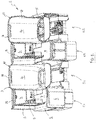
Figure 3 is a sectioned plan view of part of the seating installation ofFigures 1 and2 ; -
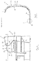
Figure 4 is an enlarged view of part of the sectioned plan view ofFigure 3 ; -
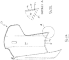
Figure 5A is a perspective view of an upholstery component being part of a panel assembly embodying one aspect of the invention; and -
Figure 5B is an enlarged view of part of the upholstery component ofFigure 5A . - Referring now to the drawings there is shown generally indicated as 10 a panel assembly embodying one aspect of the invention. The illustrated
panel assembly 10 is configured for use as upholstery for a vehicle, especially an aircraft. In particular, the illustratedpanel assembly 10 may be used to upholster anaircraft seating installation 2, which includes ashell structure 3 shaped to accommodate one or more seats (not shown), typically seats that recline to serve as a bed. In the example ofFigure 1 , theshell structure 3 includes two seat stations S1, S2 and a respective console C1, C2 adjacent each seat station S1, S2. Theshell structure 3 typically includes multiple surfaces that a seated or reclined passenger comes into contact with, for examplerear seat walls 4, side seat walls 5, console walls 6,console tops 7 andpartitions 8. Panel assemblies embodying the invention may be configured, i.e. suitable shaped and sized, to upholster any one or more of such surfaces. In the specific example illustrated inFigures 3 ,4 ,5A and 5B , thepanel assembly 10 is shaped and dimensioned to upholster arear seat wall 4 although it will be understood that the invention is not limited by this. - The
panel assembly 10 comprises abase structure 12 and anupholstery component 13 comprising alayer 14 of resiliently deformable material. The upholstery component covers, thereby upholstering, anobverse face 16 of thebase structure 12. - The
upholstery component 13 is typically located (directly or indirectly) against theobverse face 16 but is removable, i.e. not stuck to theobverse face 16 by any adhesive or other permanent fixing. - The
upholstery component 13 is releasably retained on thebase structure 12, typically held against theobverse face 16, by at least oneclip 18 that extends along at least part of at least oneedge 20 of thepanel assembly 10. - Typically, the
panel assembly 10 hasmultiple edges 20 and a respective one ormore clips 18 may be located along any one or more of theedges 20 as required. In some instances, arespective clip 18 is provided around all of theedges 20 of thepanel assembly 10. - Optionally, the
clip 18 is dimensioned to extend along substantially an entire respective edge of thepanel assembly 10. Alternatively, two ormore clips 18 may be provided end-to-end along arespective edge 20. - The
panel assembly 10 may include arespective corner 22 between adjacentnon-parallel edges 20, a respectiveseparate clip 18 shaped and dimensioned to extend around thecorner 22 may be provided or theclip 18 extending along theadjacent edges 20 may be shaped to extend around thecorner 22, as is convenient. - In preferred embodiments, the
clip 18 has first and second opposingjaws jaws upholstery component 13 on thebase structure 12. The gripping force is in a direction that is substantially perpendicular with theobverse face 16. Typically, when gripping, thefirst jaw 24 engages with an obverse surface 28 of thepanel assembly 10, which is typically the obverse surface of theupholstery component 13. Thesecond jaw 26 engages with a reverse surface 32 of thepanel assembly 10. - Preferably, one or both of obverse and reverse surfaces 28, 32 are shaped to define a
respective recess 34, 36 for receiving therespective jaw recess 34, 36 is conveniently formed in therespective edge 20 of thepanel assembly 10, and may extend along substantially the whole length of therespective edge 20, or at least as long as the length of thecorresponding clip 18. - Preferably the
clip 18, or at least part of it, is formed from flexible, resilient material and is shaped to be biased into a gripping state such that the first andsecond jaws - Typically the
clip 18 has anelongate body 19, which may be substantially linear or curved to suit the contour of thepanel assembly 10. Thebody 19, or at least a part of thebody 19, may have a substantially U-shaped or C-shaped cross section, the legs of the U or C shape serving as a respective one of thejaws body 19, or at least the U or C shaped part of it, may be formed from flexible resilient material. In alternative embodiments, any convenient alternative type of conventional clip may be used, e.g. spring biased scissor clips or wedge clips. - In any event, in preferred embodiments the
clip 18 grips thepanel assembly 10 holding theupholstery component 13 in place, conveniently by its own resilience. - In typical embodiments, the
upholstery component 13 includes acover 30 that covers at least the obverse face of thelayer 14. Thecover 30 may cover only the obverse face of thelayer 14, or it may cover all of the surfaces of thelayer 14. In any case, thecover 30 thus provides the obverse face of thepanel assembly 10. Thecover 30 may take any convenient form, for example comprising a layer of material applied only to the obverse face of thelayer 14, or to more than one surface of thelayer 14, for example covering all surfaces of thelayer 14. The cover material may be any suitable conventional material for example real leather, artificial leather, fabric or synthetic material. The cover material may be fixed to thelayer 14 by any convenient fixing means, typically by adhesive. - In typical embodiments, the resilient
deformable layer 14 is formed from foam, preferably a semi-rigid foam. Optionally a memory foam may be used to providelayer 14. The foam may for example be a polymer foam, especially a closed cell polymer foam, typically a cross-linked polymer foam. For example, semi-rigid foams provided by Zotefoam Plc of Croydon, England under the brand names ZOTE or ZOTEK may be used to provide thelayer 14. Advantageously thefoam layer 14 is compressed between rollers (not shown) or plates (not shown) prior to its incorporation into thepanel assembly 10. The compression typically reduces the depth of thelayer 14, for example by approximately 25%. Advantageously, this has the effect of softening the foam and altering its natural resilience to improve its ability to recover its original shape after deformation. - Optionally, the
upholstery component 13 includes asubstrate layer 15 on which the resilientlydeformable layer 14 is mounted. Thesubstrate layer 15 may be fixed directly or indirectly to the reverse face of the resilientlydeformable layer 14, i.e. one or more intermediate layers (e.g. part of the cover 30) may be located between thesubstrate layer 15 and thedeformable layer 14. Thesubstrate layer 15 may be fixed in place by any suitable means, conveniently adhesive. Thesubstrate 15 may be dimensioned to project laterally beyond the one or more of the edges of the resiliently deformable layer 14 (as can best be seen fromFigures 5A and 5B ). Conveniently, the projecting portion of thesubstrate layer 15 defines, together with the edge of the resilientlydeformable layer 14, therecess 34. In such embodiments, theclip 18, inparticular jaw 24, may grip the projecting portion of thesubstrate layer 15 to hold theupholstery component 13 to thebase structure 12. Thecover 30 may cover only the resilientlydeformable layer 14 or may also cover the substrate layer 15 (or at least its projecting portion) as desired. In preferred embodiments, thesubstrate layer 15 is formed from a rigid or semi-rigid material, for example a metallic, polymeric or composite material. - As can best be seen from
Figure 1 , advantageously the, or each,clip 18 serves as a trim rail around the periphery of seating installation, or other structure, of which therespective panel assembly 10 is part. - The
base structure 12 is typically substantially rigid. Thebase structure 12 may comprise aback component 40, which is typically rigid or semi-rigid and may comprise a sheet, plate or frame, and may for example be formed from metal, polymeric material or a composite material e.g. fibre reinforced plastics, wood or fibreboard. Theback component 40 has a reverse face that provides the reverse face of thebase structure 12 and which may also provide the reverse surface 32 in which recess 36 may be formed. - In some embodiments, the obverse face of the
back component 40 may provide theobverse face 16 of thebase structure 12. In such embodiments, theupholstery component 13 may be held against the obverse face of theback component 40. In other embodiments, including the illustrated embodiment, thebase structure 12 includes one or more intermediate structures between theback component 40 and theupholstery component 13, in which case theobverse face 16 is provided by one or more of the intermediate structure(s). In the illustrated embodiment anintermediate structure 41 is provided between theback component 40 and theupholstery component 13, the obverse face of theintermediate structure 41 providing theobverse face 16 of thebase structure 12. Theintermediate structure 41 is a frame, typically a metal frame (which usually includes weight saving apertures 42), but may take alternative forms in other embodiments. - The
base structure 12 may take whatever shape is required by its purpose and may be planar, curved or contoured accordingly. In typical embodiments, theupholstery component 13 is shaped and dimensioned to match the shape and dimensions of theobverse face 16 of thebase structure 12. - The
base structure 12 may be a standalone structure that may be fitted to another structure, e.g. a seating installation, or may be an integral part of another structure, e.g. a seating installation. In the illustrated embodiment, thebase structure 12 is assumed to be part of theshell 3 that provides therear seat wall 4. - It will be apparent that panel assemblies embodying the invention are particularly suited for use in upholstering the interiors of aircraft, especially an aircraft seating installation, wherein it may be shaped and dimensioned for upholstering any part of the
shell 3, or any other surface with which a passenger may come into contact. - Panel assemblies embodying the invention may be alternatively be used upholstering other vehicles, for example, trains, boats or recreational vehicles, or other environments for accommodating people, for example cabins, caravans, mobile homes or theatres.
- While panel assemblies embodying the invention are well suited for upholstering seating installations, they may also be used elsewhere, e.g. on walls, partitions, around beds, and on any other surface that is likely to come into contact with a user.
- It will be apparent that panel assemblies embodying the invention provide a soft feel to passengers and other users while being sufficiently resilient to regain their original shape after deformation. Moreover, by removing the
clips 18, or removing theupholstery component 13 from theclips 18, theupholstery component 13 can be easily removed to be cleaned, repaired, or replaced. - In a preferred manufacturing process, the material from which the
layer 14 is formed is cut to the required shape and size after which thelayer 14 is crushed, for example between rollers (e.g. using a mangle) or plates to reduce the thickness of thelayer 14. This facilitates handling the material including reducing the risk that thelayer 14 is marked by fingerprints during the manufacturing process. Next thecover 30 is fixed to the crushedlayer 14. The assembledcover 30 andlayer 14 may then be vacuum formed and/or trimmed as required. The assembledcover 30 andlayer 14 are preferably crushed at least once (e.g. 2 or 3 times) for example between rollers (e.g. using a mangle) or plates. - The invention is not limited by the embodiments described herein which may be modified or varied without departing from the scope of the appended claims.
Claims (15)
- A seating installation (2) comprising a shell structure (3) located around one or more seats (S1, S2), and at least one panel assembly shaped and dimensioned to provide one or more surfaces of the shell structure, the or each panel assembly (10) comprising:a base structure (12); andan upholstery component (13) comprising a layer (14) of resiliently deformable material, the upholstery component covering an obverse face (16) of said base structure,characterised in that at least one clip (18) extends along at least part of at least one edge (20) of the panel assembly, said at least one clip having first and second opposing jaws (24, 26),wherein said first and second jaws (24, 26) are resiliently biased towards each other to exert a gripping force substantially perpendicular to the plane of said obverse face to releasably retain said upholstery component (13) on said base structure (12), and in that said first jaw (24) releasably engages with an obverse surface of said panel assembly and said second jaw (26) releasably engages with a reverse surface of said panel assembly, and wherein said at least one clip (18) is removable and serves as a trim rail around the periphery of the shell structure (3).
- The seating installation (2) of claim 1, wherein the or each panel assembly has a plurality of edges (20), a respective one or more of said at least one clips (18) extending along each edge.
- The seating installation (2) of claim 1 or 2 wherein the or each clip (18) extends along substantially a whole length of the respective edge (20) of the or each panel assembly (10).
- The seating installation (2) as claimed in any preceding claim wherein said at least one clip is the trim rail that extends around the periphery of said the or each panel assembly.
- The seating installation (2) as claimed in claim 4, wherein one or both of said obverse surface (28) and said reverse surface (32) is shaped to define a respective recess (34, 36) for engagement by said first or second jaw (24, 26) respectively and wherein the respective recess is formed along a respective edge (20) of said the or each panel assembly.
- The seating installation (2) of any preceding claim wherein said at least one clip (18) comprises an elongate body (19) at least part of which has a substantially U-shaped or C-shaped cross section.
- The seating installation (2) of any preceding claim wherein said at least one clip (18) is formed from flexible resilient material.
- The seating installation (2) of any preceding claim wherein said upholstery component (13) includes a cover (30) covering at least an obverse face of said resilient deformable layer (14).
- The seating installation (2)of any preceding claim wherein the resiliently deformable layer (14) comprises a layer of foam, preferably a closed cell polymer foam.
- The seating installation (2) of any preceding claim, wherein said upholstery component (13) includes a substrate layer (16), said layer of resiliently deformable material being provided on said substrate layer, and wherein said substrate layer is preferably substantially rigid or semi-rigid.
- The seating installation (2) of claim 10 wherein a portion of said substrate layer (16) projects laterally from one or more edges of said resiliently deformable layer, and wherein preferably said at least one clip (18) engages, in use, with said projecting portion of said substrate layer.
- The seating installation (2)of any preceding claim wherein said base structure (12) is substantially rigid.
- The seating installation (2) of any preceding claim, wherein the panel assembly is shaped and dimensioned to provide part of the shell structure (3) of a vehicle or personal accommodation environment (2).
- The seating installation (2)of claim 13, wherein said at least one clip (18) is the crim rail extending around all or part of an edge of said shell structure (3).
- A seating installation (2) as claimed in any preceding claim, said one or more surfaces of the shell structure provided by the at least one panel assembly optionally including any one or more of a rear seat wall (4), a side seat wall (5), a console wall (6), a console top (7) and/or a partition (8).
Applications Claiming Priority (1)
| Application Number | Priority Date | Filing Date | Title |
|---|---|---|---|
| GB1417241.5A GB2530743B (en) | 2014-09-30 | 2014-09-30 | A Panel Assembly |
Publications (2)
| Publication Number | Publication Date |
|---|---|
| EP3002219A1 EP3002219A1 (en) | 2016-04-06 |
| EP3002219B1 true EP3002219B1 (en) | 2021-03-17 |
Family
ID=51901359
Family Applications (1)
| Application Number | Title | Priority Date | Filing Date |
|---|---|---|---|
| EP15186281.0A Active EP3002219B1 (en) | 2014-09-30 | 2015-09-22 | A seating installation |
Country Status (3)
| Country | Link |
|---|---|
| US (1) | US9862492B2 (en) |
| EP (1) | EP3002219B1 (en) |
| GB (1) | GB2530743B (en) |
Families Citing this family (1)
| Publication number | Priority date | Publication date | Assignee | Title |
|---|---|---|---|---|
| GB2548415A (en) * | 2016-03-18 | 2017-09-20 | Acro Aircraft Seating Ltd | Seat back and insert |
Family Cites Families (16)
| Publication number | Priority date | Publication date | Assignee | Title |
|---|---|---|---|---|
| FR1288740A (en) * | 1960-08-25 | 1962-03-30 | Citroen Sa Andre | Trim panel and its fixing, in particular for vehicles |
| US3281185A (en) * | 1965-06-24 | 1966-10-25 | Miller Herman Inc | Furniture construction |
| GB1131107A (en) * | 1965-12-17 | 1968-10-23 | Bostrom Mfg Company Ltd | Improvements in and relating to seats and seat cover fixing means |
| US4396226A (en) * | 1979-09-14 | 1983-08-02 | Denack Design Corporation | Structural component assembly for upholstered furniture and method of making |
| US4432521A (en) * | 1981-06-22 | 1984-02-21 | Jack Douglas | Cradle case |
| DE3609591A1 (en) * | 1986-03-21 | 1988-01-21 | Grammer Sitzsysteme Gmbh | SEAT |
| US5601333A (en) * | 1995-09-11 | 1997-02-11 | H. O. Bostram Company, Inc. | Seat retention system |
| GB9824704D0 (en) * | 1998-11-12 | 1999-01-06 | Mgr Foamtex Ltd | Aircraft seats |
| US6726278B1 (en) * | 2003-06-13 | 2004-04-27 | First Source Furniture Group Llc | Back pad for chair back |
| US7775589B1 (en) * | 2006-03-15 | 2010-08-17 | Sava Cvek | Upholstery mounting system and mechanism |
| CN101273857A (en) * | 2007-03-28 | 2008-10-01 | 王妙玲 | New type closet seat pad and method for manufacturing same |
| US7871039B2 (en) * | 2007-05-22 | 2011-01-18 | The Boeing Company | Modular passenger seat for an aircraft |
| JP5374859B2 (en) * | 2007-11-07 | 2013-12-25 | トヨタ紡織株式会社 | Locking structure of hook member and skin material |
| GB2485822B (en) * | 2010-11-25 | 2018-02-21 | Mgr Foamtex Ltd | Improvements in and relating to interior trim components for aircraft cabins |
| JP5876255B2 (en) * | 2011-09-08 | 2016-03-02 | 株式会社イレブンインターナショナル | Seat cover and cover fitting |
| US8870283B2 (en) * | 2013-03-15 | 2014-10-28 | Brica, Inc. | Vehicle seat protector |
-
2014
- 2014-09-30 GB GB1417241.5A patent/GB2530743B/en active Active
-
2015
- 2015-09-22 EP EP15186281.0A patent/EP3002219B1/en active Active
- 2015-09-30 US US14/870,210 patent/US9862492B2/en active Active
Non-Patent Citations (1)
| Title |
|---|
| None * |
Also Published As
| Publication number | Publication date |
|---|---|
| GB2530743A (en) | 2016-04-06 |
| US9862492B2 (en) | 2018-01-09 |
| EP3002219A1 (en) | 2016-04-06 |
| GB201417241D0 (en) | 2014-11-12 |
| GB2530743B (en) | 2021-06-09 |
| US20160090182A1 (en) | 2016-03-31 |
Similar Documents
| Publication | Publication Date | Title |
|---|---|---|
| US9708067B2 (en) | Seat cushion for use by airline passengers | |
| US9315131B2 (en) | Suspension seat back and cushion system having an inner suspension panel | |
| US20120032486A1 (en) | Vehicle seat construction | |
| WO2010012910A3 (en) | Seat module for an aircraft passenger | |
| US10117521B2 (en) | Upholstered furniture piece having upholstered arm panels | |
| JP2012046181A5 (en) | ||
| EP3250400B1 (en) | Lightweight seat for vehicles | |
| WO2012086546A1 (en) | Vehicle seat cushion | |
| CN108349590A (en) | aircraft seating device | |
| US20150284093A1 (en) | Lightweight upholstery cover with edge attachment | |
| US8584333B2 (en) | Method for manufacturing a vehicle seat cushion assembly | |
| US9862492B2 (en) | Panel assembly | |
| CN107000846B (en) | Seat pan assembly with encapsulated comfort spring | |
| JP2017081370A (en) | pad | |
| US20080252131A1 (en) | Automotive vehicle seat back and method of making same | |
| US20160375806A1 (en) | Connection of a motor vehicle seat trim element to a cover part | |
| EP3634854B1 (en) | Seat cushion for airline passengers | |
| CA3000138A1 (en) | An overlay | |
| EP3140112B1 (en) | Foam article | |
| JP6213370B2 (en) | Vehicle seat with sliding mechanism | |
| US20170291524A1 (en) | Comfort system for seating backs with reduction in pur volume and environmentally friendly construction | |
| KR20080001091U (en) | Chair with space mattress | |
| JP2945991B2 (en) | Seat | |
| CN108340818B (en) | Comfortable bracket for chair back | |
| JP2005211251A (en) | Vehicle seat cushion pad |
Legal Events
| Date | Code | Title | Description |
|---|---|---|---|
| PUAI | Public reference made under article 153(3) epc to a published international application that has entered the european phase |
Free format text: ORIGINAL CODE: 0009012 |
|
| AK | Designated contracting states |
Kind code of ref document: A1 Designated state(s): AL AT BE BG CH CY CZ DE DK EE ES FI FR GB GR HR HU IE IS IT LI LT LU LV MC MK MT NL NO PL PT RO RS SE SI SK SM TR |
|
| AX | Request for extension of the european patent |
Extension state: BA ME |
|
| 17P | Request for examination filed |
Effective date: 20161004 |
|
| RBV | Designated contracting states (corrected) |
Designated state(s): AL AT BE BG CH CY CZ DE DK EE ES FI FR GB GR HR HU IE IS IT LI LT LU LV MC MK MT NL NO PL PT RO RS SE SI SK SM TR |
|
| STAA | Information on the status of an ep patent application or granted ep patent |
Free format text: STATUS: EXAMINATION IS IN PROGRESS |
|
| 17Q | First examination report despatched |
Effective date: 20170221 |
|
| GRAP | Despatch of communication of intention to grant a patent |
Free format text: ORIGINAL CODE: EPIDOSNIGR1 |
|
| STAA | Information on the status of an ep patent application or granted ep patent |
Free format text: STATUS: GRANT OF PATENT IS INTENDED |
|
| INTG | Intention to grant announced |
Effective date: 20200925 |
|
| GRAS | Grant fee paid |
Free format text: ORIGINAL CODE: EPIDOSNIGR3 |
|
| GRAA | (expected) grant |
Free format text: ORIGINAL CODE: 0009210 |
|
| STAA | Information on the status of an ep patent application or granted ep patent |
Free format text: STATUS: THE PATENT HAS BEEN GRANTED |
|
| AK | Designated contracting states |
Kind code of ref document: B1 Designated state(s): AL AT BE BG CH CY CZ DE DK EE ES FI FR GB GR HR HU IE IS IT LI LT LU LV MC MK MT NL NO PL PT RO RS SE SI SK SM TR |
|
| REG | Reference to a national code |
Ref country code: GB Ref legal event code: FG4D |
|
| REG | Reference to a national code |
Ref country code: CH Ref legal event code: EP |
|
| REG | Reference to a national code |
Ref country code: DE Ref legal event code: R096 Ref document number: 602015066903 Country of ref document: DE |
|
| REG | Reference to a national code |
Ref country code: IE Ref legal event code: FG4D |
|
| REG | Reference to a national code |
Ref country code: AT Ref legal event code: REF Ref document number: 1372018 Country of ref document: AT Kind code of ref document: T Effective date: 20210415 |
|
| REG | Reference to a national code |
Ref country code: LT Ref legal event code: MG9D |
|
| PG25 | Lapsed in a contracting state [announced via postgrant information from national office to epo] |
Ref country code: FI Free format text: LAPSE BECAUSE OF FAILURE TO SUBMIT A TRANSLATION OF THE DESCRIPTION OR TO PAY THE FEE WITHIN THE PRESCRIBED TIME-LIMIT Effective date: 20210317 Ref country code: GR Free format text: LAPSE BECAUSE OF FAILURE TO SUBMIT A TRANSLATION OF THE DESCRIPTION OR TO PAY THE FEE WITHIN THE PRESCRIBED TIME-LIMIT Effective date: 20210618 Ref country code: HR Free format text: LAPSE BECAUSE OF FAILURE TO SUBMIT A TRANSLATION OF THE DESCRIPTION OR TO PAY THE FEE WITHIN THE PRESCRIBED TIME-LIMIT Effective date: 20210317 Ref country code: BG Free format text: LAPSE BECAUSE OF FAILURE TO SUBMIT A TRANSLATION OF THE DESCRIPTION OR TO PAY THE FEE WITHIN THE PRESCRIBED TIME-LIMIT Effective date: 20210617 Ref country code: NO Free format text: LAPSE BECAUSE OF FAILURE TO SUBMIT A TRANSLATION OF THE DESCRIPTION OR TO PAY THE FEE WITHIN THE PRESCRIBED TIME-LIMIT Effective date: 20210617 |
|
| REG | Reference to a national code |
Ref country code: AT Ref legal event code: MK05 Ref document number: 1372018 Country of ref document: AT Kind code of ref document: T Effective date: 20210317 |
|
| REG | Reference to a national code |
Ref country code: NL Ref legal event code: MP Effective date: 20210317 |
|
| PG25 | Lapsed in a contracting state [announced via postgrant information from national office to epo] |
Ref country code: RS Free format text: LAPSE BECAUSE OF FAILURE TO SUBMIT A TRANSLATION OF THE DESCRIPTION OR TO PAY THE FEE WITHIN THE PRESCRIBED TIME-LIMIT Effective date: 20210317 Ref country code: LV Free format text: LAPSE BECAUSE OF FAILURE TO SUBMIT A TRANSLATION OF THE DESCRIPTION OR TO PAY THE FEE WITHIN THE PRESCRIBED TIME-LIMIT Effective date: 20210317 Ref country code: SE Free format text: LAPSE BECAUSE OF FAILURE TO SUBMIT A TRANSLATION OF THE DESCRIPTION OR TO PAY THE FEE WITHIN THE PRESCRIBED TIME-LIMIT Effective date: 20210317 |
|
| PG25 | Lapsed in a contracting state [announced via postgrant information from national office to epo] |
Ref country code: NL Free format text: LAPSE BECAUSE OF FAILURE TO SUBMIT A TRANSLATION OF THE DESCRIPTION OR TO PAY THE FEE WITHIN THE PRESCRIBED TIME-LIMIT Effective date: 20210317 |
|
| PG25 | Lapsed in a contracting state [announced via postgrant information from national office to epo] |
Ref country code: SM Free format text: LAPSE BECAUSE OF FAILURE TO SUBMIT A TRANSLATION OF THE DESCRIPTION OR TO PAY THE FEE WITHIN THE PRESCRIBED TIME-LIMIT Effective date: 20210317 Ref country code: CZ Free format text: LAPSE BECAUSE OF FAILURE TO SUBMIT A TRANSLATION OF THE DESCRIPTION OR TO PAY THE FEE WITHIN THE PRESCRIBED TIME-LIMIT Effective date: 20210317 Ref country code: EE Free format text: LAPSE BECAUSE OF FAILURE TO SUBMIT A TRANSLATION OF THE DESCRIPTION OR TO PAY THE FEE WITHIN THE PRESCRIBED TIME-LIMIT Effective date: 20210317 Ref country code: LT Free format text: LAPSE BECAUSE OF FAILURE TO SUBMIT A TRANSLATION OF THE DESCRIPTION OR TO PAY THE FEE WITHIN THE PRESCRIBED TIME-LIMIT Effective date: 20210317 Ref country code: AT Free format text: LAPSE BECAUSE OF FAILURE TO SUBMIT A TRANSLATION OF THE DESCRIPTION OR TO PAY THE FEE WITHIN THE PRESCRIBED TIME-LIMIT Effective date: 20210317 |
|
| PG25 | Lapsed in a contracting state [announced via postgrant information from national office to epo] |
Ref country code: IS Free format text: LAPSE BECAUSE OF FAILURE TO SUBMIT A TRANSLATION OF THE DESCRIPTION OR TO PAY THE FEE WITHIN THE PRESCRIBED TIME-LIMIT Effective date: 20210717 Ref country code: ES Free format text: LAPSE BECAUSE OF FAILURE TO SUBMIT A TRANSLATION OF THE DESCRIPTION OR TO PAY THE FEE WITHIN THE PRESCRIBED TIME-LIMIT Effective date: 20210317 Ref country code: PT Free format text: LAPSE BECAUSE OF FAILURE TO SUBMIT A TRANSLATION OF THE DESCRIPTION OR TO PAY THE FEE WITHIN THE PRESCRIBED TIME-LIMIT Effective date: 20210719 Ref country code: PL Free format text: LAPSE BECAUSE OF FAILURE TO SUBMIT A TRANSLATION OF THE DESCRIPTION OR TO PAY THE FEE WITHIN THE PRESCRIBED TIME-LIMIT Effective date: 20210317 Ref country code: SK Free format text: LAPSE BECAUSE OF FAILURE TO SUBMIT A TRANSLATION OF THE DESCRIPTION OR TO PAY THE FEE WITHIN THE PRESCRIBED TIME-LIMIT Effective date: 20210317 Ref country code: RO Free format text: LAPSE BECAUSE OF FAILURE TO SUBMIT A TRANSLATION OF THE DESCRIPTION OR TO PAY THE FEE WITHIN THE PRESCRIBED TIME-LIMIT Effective date: 20210317 |
|
| REG | Reference to a national code |
Ref country code: DE Ref legal event code: R097 Ref document number: 602015066903 Country of ref document: DE |
|
| PLBE | No opposition filed within time limit |
Free format text: ORIGINAL CODE: 0009261 |
|
| STAA | Information on the status of an ep patent application or granted ep patent |
Free format text: STATUS: NO OPPOSITION FILED WITHIN TIME LIMIT |
|
| PG25 | Lapsed in a contracting state [announced via postgrant information from national office to epo] |
Ref country code: DK Free format text: LAPSE BECAUSE OF FAILURE TO SUBMIT A TRANSLATION OF THE DESCRIPTION OR TO PAY THE FEE WITHIN THE PRESCRIBED TIME-LIMIT Effective date: 20210317 Ref country code: AL Free format text: LAPSE BECAUSE OF FAILURE TO SUBMIT A TRANSLATION OF THE DESCRIPTION OR TO PAY THE FEE WITHIN THE PRESCRIBED TIME-LIMIT Effective date: 20210317 |
|
| 26N | No opposition filed |
Effective date: 20211220 |
|
| PG25 | Lapsed in a contracting state [announced via postgrant information from national office to epo] |
Ref country code: SI Free format text: LAPSE BECAUSE OF FAILURE TO SUBMIT A TRANSLATION OF THE DESCRIPTION OR TO PAY THE FEE WITHIN THE PRESCRIBED TIME-LIMIT Effective date: 20210317 |
|
| REG | Reference to a national code |
Ref country code: CH Ref legal event code: PL |
|
| REG | Reference to a national code |
Ref country code: BE Ref legal event code: MM Effective date: 20210930 |
|
| PG25 | Lapsed in a contracting state [announced via postgrant information from national office to epo] |
Ref country code: IS Free format text: LAPSE BECAUSE OF FAILURE TO SUBMIT A TRANSLATION OF THE DESCRIPTION OR TO PAY THE FEE WITHIN THE PRESCRIBED TIME-LIMIT Effective date: 20210717 Ref country code: MC Free format text: LAPSE BECAUSE OF FAILURE TO SUBMIT A TRANSLATION OF THE DESCRIPTION OR TO PAY THE FEE WITHIN THE PRESCRIBED TIME-LIMIT Effective date: 20210317 |
|
| PG25 | Lapsed in a contracting state [announced via postgrant information from national office to epo] |
Ref country code: LU Free format text: LAPSE BECAUSE OF NON-PAYMENT OF DUE FEES Effective date: 20210922 Ref country code: IE Free format text: LAPSE BECAUSE OF NON-PAYMENT OF DUE FEES Effective date: 20210922 Ref country code: BE Free format text: LAPSE BECAUSE OF NON-PAYMENT OF DUE FEES Effective date: 20210930 |
|
| PG25 | Lapsed in a contracting state [announced via postgrant information from national office to epo] |
Ref country code: LI Free format text: LAPSE BECAUSE OF NON-PAYMENT OF DUE FEES Effective date: 20210930 Ref country code: CH Free format text: LAPSE BECAUSE OF NON-PAYMENT OF DUE FEES Effective date: 20210930 |
|
| PG25 | Lapsed in a contracting state [announced via postgrant information from national office to epo] |
Ref country code: HU Free format text: LAPSE BECAUSE OF FAILURE TO SUBMIT A TRANSLATION OF THE DESCRIPTION OR TO PAY THE FEE WITHIN THE PRESCRIBED TIME-LIMIT; INVALID AB INITIO Effective date: 20150922 |
|
| PG25 | Lapsed in a contracting state [announced via postgrant information from national office to epo] |
Ref country code: CY Free format text: LAPSE BECAUSE OF FAILURE TO SUBMIT A TRANSLATION OF THE DESCRIPTION OR TO PAY THE FEE WITHIN THE PRESCRIBED TIME-LIMIT Effective date: 20210317 |
|
| PG25 | Lapsed in a contracting state [announced via postgrant information from national office to epo] |
Ref country code: MK Free format text: LAPSE BECAUSE OF FAILURE TO SUBMIT A TRANSLATION OF THE DESCRIPTION OR TO PAY THE FEE WITHIN THE PRESCRIBED TIME-LIMIT Effective date: 20210317 |
|
| PG25 | Lapsed in a contracting state [announced via postgrant information from national office to epo] |
Ref country code: MT Free format text: LAPSE BECAUSE OF FAILURE TO SUBMIT A TRANSLATION OF THE DESCRIPTION OR TO PAY THE FEE WITHIN THE PRESCRIBED TIME-LIMIT Effective date: 20210317 |
|
| PGFP | Annual fee paid to national office [announced via postgrant information from national office to epo] |
Ref country code: DE Payment date: 20250919 Year of fee payment: 11 |
|
| PGFP | Annual fee paid to national office [announced via postgrant information from national office to epo] |
Ref country code: IT Payment date: 20250918 Year of fee payment: 11 |
|
| PGFP | Annual fee paid to national office [announced via postgrant information from national office to epo] |
Ref country code: GB Payment date: 20250911 Year of fee payment: 11 |
|
| PGFP | Annual fee paid to national office [announced via postgrant information from national office to epo] |
Ref country code: FR Payment date: 20250922 Year of fee payment: 11 |
|
| PG25 | Lapsed in a contracting state [announced via postgrant information from national office to epo] |
Ref country code: TR Free format text: LAPSE BECAUSE OF FAILURE TO SUBMIT A TRANSLATION OF THE DESCRIPTION OR TO PAY THE FEE WITHIN THE PRESCRIBED TIME-LIMIT Effective date: 20210317 |