EP3002207A1 - Recovery systems and methods for unmanned underwater vehicles - Google Patents
Recovery systems and methods for unmanned underwater vehicles Download PDFInfo
- Publication number
- EP3002207A1 EP3002207A1 EP15184437.0A EP15184437A EP3002207A1 EP 3002207 A1 EP3002207 A1 EP 3002207A1 EP 15184437 A EP15184437 A EP 15184437A EP 3002207 A1 EP3002207 A1 EP 3002207A1
- Authority
- EP
- European Patent Office
- Prior art keywords
- uuv
- load
- recovery system
- water
- release mechanism
- Prior art date
- Legal status (The legal status is an assumption and is not a legal conclusion. Google has not performed a legal analysis and makes no representation as to the accuracy of the status listed.)
- Granted
Links
Images





Classifications
-
- B—PERFORMING OPERATIONS; TRANSPORTING
- B63—SHIPS OR OTHER WATERBORNE VESSELS; RELATED EQUIPMENT
- B63G—OFFENSIVE OR DEFENSIVE ARRANGEMENTS ON VESSELS; MINE-LAYING; MINE-SWEEPING; SUBMARINES; AIRCRAFT CARRIERS
- B63G8/00—Underwater vessels, e.g. submarines; Equipment specially adapted therefor
- B63G8/14—Control of attitude or depth
-
- B—PERFORMING OPERATIONS; TRANSPORTING
- B63—SHIPS OR OTHER WATERBORNE VESSELS; RELATED EQUIPMENT
- B63G—OFFENSIVE OR DEFENSIVE ARRANGEMENTS ON VESSELS; MINE-LAYING; MINE-SWEEPING; SUBMARINES; AIRCRAFT CARRIERS
- B63G8/00—Underwater vessels, e.g. submarines; Equipment specially adapted therefor
- B63G8/14—Control of attitude or depth
- B63G8/24—Automatic depth adjustment; Safety equipment for increasing buoyancy, e.g. detachable ballast, floating bodies
-
- B—PERFORMING OPERATIONS; TRANSPORTING
- B63—SHIPS OR OTHER WATERBORNE VESSELS; RELATED EQUIPMENT
- B63G—OFFENSIVE OR DEFENSIVE ARRANGEMENTS ON VESSELS; MINE-LAYING; MINE-SWEEPING; SUBMARINES; AIRCRAFT CARRIERS
- B63G8/00—Underwater vessels, e.g. submarines; Equipment specially adapted therefor
- B63G8/001—Underwater vessels adapted for special purposes, e.g. unmanned underwater vessels; Equipment specially adapted therefor, e.g. docking stations
- B63G2008/002—Underwater vessels adapted for special purposes, e.g. unmanned underwater vessels; Equipment specially adapted therefor, e.g. docking stations unmanned
Definitions
- This disclosure relates to the field of recovery of Unmanned Underwater Vehicles (UUVs).
- UUVs Unmanned Underwater Vehicles
- UUVs may be irretrievably lost during underwater operation and be unable to return to the surface for a number of reasons.
- the UUV may inadvertently travel below a design depth, may be caught by debris or mud, may lose power and be unable to return to the surface, etc.
- UUVs are often neutrally buoyant, which may require the UUV to utilize a propulsion system to return to the surface.
- propulsion may not be available when power is lost or the UUV incurs software and/or computer failures. The result is that the UUV may drift under water, making recovery nearly impossible.
- Embodiments described herein provide UUV recovery systems and methods that utilize multiple independent release mechanisms that can detach a load and allow the UUV to float to the surface of the water.
- the independent release mechanisms are each capable of releasing the load from the UUV utilizing different release criteria, thereby rendering the UUV positively buoyant when various conditions are met.
- the recovery system includes a detachable load that renders the UUV neutrally buoyant in water.
- the recovery system further includes a plurality of release mechanisms that are configured to detach the load to render the UUV positively buoyant in the water.
- the release mechanisms include a first, second, and third release mechanism.
- the first release mechanism is configured to detach the load in response to a command signal.
- the second release mechanism is configured to detach the load in response to the UUV being submerged in the water beyond a threshold time.
- the third release mechanism is configured to detach the load in response to the UUV exceeding a maximum depth in the water.
- the recovery system includes a detachable load, a first release mechanism, a second release mechanism, and a third release mechanism.
- the load is configured to render the UUV positively buoyant in water upon release.
- the first release mechanism is configured to detach the load in response to a command signal.
- the second release mechanism is configured to detach the load in response to the UUV being submerged in the water beyond a threshold time.
- the third release mechanism is configured to detach the load in response to the UUV exceeding a maximum depth in the water.
- Another embodiment is a method for operating a recovery system for an Unmanned Underwater Vehicle (UUV).
- the method comprises affixing a detachable load that renders the UUV neutrally buoyant in water.
- the method further comprises detaching the load in response to a command signal to render the UUV positively buoyant in the water.
- the method further comprises detaching the load in response to the UUV being submerged in the water beyond a threshold time to render the UUV positively buoyant in the water.
- the method further comprises detaching the load in response to the UUV exceeding a maximum depth in the water to render the UUV positively buoyant in the water.
- FIG. 1 illustrates a submersible vehicle 100 that utilizes a recovery system in an exemplary embodiment.
- vehicle 100 is depicted as an Unmanned Underwater Vehicle (UUV), although in other embodiments, vehicle 100 may be any type of vehicle that is able to submerge under water and utilize a recovery system to ensure that vehicle 100 may be recovered at the surface when various recovery criteria are met. For instance, vehicle 100 may inadvertently dive past a pre-determined depth, which triggers the recovery system to return vehicle 100 to the surface. Vehicle 100 may exceed a pre-determined amount of time under water, which triggers the recovery system to return vehicle 100 to the surface. Vehicle 100, or some other entity, may generate a command signal which triggers the recovery system to return vehicle 100 to the surface.
- UUV Unmanned Underwater Vehicle
- FIG. 2 is a block diagram of a recovery system 200 for vehicle 100 of FIG. 1 in an exemplary embodiment.
- recovery system 200 includes a plurality of release mechanisms 202-204 that are mechanically coupled to a detachable load 206.
- Load 206 may include a portion of vehicle 100 and/or a drop weight that is able to be detached from vehicle 100 in some embodiments.
- load 206 renders vehicle 100 substantially neutrally buoyant in water, and renders vehicle 100 positively buoyant in water when load 206 is released from vehicle 100. When load 206 is released, vehicle 100 is able to float to the surface of the water and be recovered.
- Release mechanisms 202-204 operate substantially independently to ensure that load 206 is detached from vehicle 100 when certain conditions are met. This ensures vehicle 100 may be recovered.
- Release mechanism 202 in this embodiment comprises any component, system, or device that is able to detach load 206 in response to a command signal.
- the command signal may be generated by vehicle 100 and/or by another entity, such as a support vessel. For instance, vehicle 100 may generate a command signal to detach load 206 if vehicle 100 becomes stuck and is unable to surface (e.g., stuck in mud, ensnared in fishing gear, etc.).
- Release mechanism 203 in this embodiment comprises any component, system, or device that is able to detach load 206 in response to vehicle 100 being submerged in the water beyond a pre-determined time. For instance, if vehicle 100 loses power and drifts under water beyond a pre-determined amount time, then release mechanism 203 acts to detach load 206 and cause vehicle 100 to float to the surface of the water.
- Release mechanism 204 in this embodiment comprises any component, system, or device that is able to detach load 206 in response to vehicle 100 exceeding a maximum depth in the water. For instance, if vehicle 100 loses power or becomes negatively buoyant, then vehicle 100 may sink below a pre-determined depth in the water. In this case, release mechanism 204 acts to detach load 206 and cause vehicle 100 to float to the surface of the water.
- release mechanisms 202-204 act substantially independently of each other to detach load 206 and render vehicle 100 positively buoyant, vehicle 100 is more likely to be recovered on the surface of the water in response to a variety of possible failures that may otherwise cause vehicle 100 to be lost.
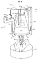
- FIG. 3 is an isometric view of another recovery system 300 for vehicle 100 in an exemplary embodiment.
- recovery system 300 includes a plurality of release mechanisms (not visible in this view) which are surrounded by a housing 306.
- Housing 306 of recovery system 300 is fixed to a shell 304, which surrounds a detachable load 302.
- load 302 is a drop weight, although in other embodiments load 302 may include portion(s) of vehicle 100.
- load 302 may be an instrument package for vehicle 100, may be external lights for vehicle 100, etc. Thus, it is not intended that load 302 in this embodiment be limited to only drop weights.
- load 302 is able to slide within shell 304 and detach from recovery system 300 when certain conditions are met. While load 302 remains connected to recovery system 300 (which is part of or is mounted to vehicle 100), vehicle 100 is approximately neutrally buoyant. This allows vehicle 100 to operate under water without incurring a buoyancy penalty (e.g., either positively or negatively) when utilizing recovery system 300. However, when load 302 is dropped, released, detached, etcetera, from recovery system 300 (and consequentially also from vehicle 100), vehicle 100 becomes positively buoyant. With positive buoyancy, vehicle 100 floats to the surface of the water, which allows for the recovery of vehicle 100.
- a buoyancy penalty e.g., either positively or negatively
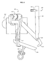
- FIG. 4 is an isometric view of release mechanisms 402-404 for recovery system 300 of FIG. 3 in an exemplary embodiment.
- housing 306 (see FIG. 3 ) has been removed to allow for the visibility of release mechanisms 402-404.
- each of release mechanisms 402-404 are capable of operating independently to detach load 302 from recovery system 300.
- Release mechanisms 402-404 are detachably coupled to a disk 405, which is mounted to load 302.
- release mechanisms 402-404 may be detachably coupled to load 302 in any number of ways as a matter of design choice.
- disk 405 is depicted as substantially round, disk 405 may include other shapes as well. For instance, disk 405 may oblong, rectangular, triangular, etc. Disk 405 may be referred to as a weigh distribution plate in some embodiments.
- Release mechanism 402 in this embodiment is an active release, and is able to detach load 302 from recovery system 300 in response to receiving a command signal.
- vehicle 100 may generate a command signal to detach load 302 from recovery system 300.
- Release mechanism 402 includes a pair of redundant actuator coils 414 which are used to release load 302, although in other embodiments only one coil 414 may be used.
- Vehicle 100 or some other entity such as a ship or an operator, may generate the command signal to release load 302 in cases where vehicle 100 is unable to return to the surface. For example, if a propulsion system for vehicle 100 fails, then vehicle 100 may generate the command signal actuating coils 414.
- Coils 414 are mechanically coupled to a fixed arm 406 (which may be bonded to housing 306) and hold a movable arm 408 in place until coils 414 are actuated.
- Movable arm 408 is rotatably coupled to fixed arm 406 by a pin 407. Upon actuation, movable arm 408 rotates out of position along a pin 407 coupled to fixed arm 406, which causes movable arm 408 to decouple from disk 405 and release load 302 from shell 304. This imparts positive buoyancy to vehicle 100 and allows vehicle 100 to float to the surface of the water for recovery.
- Release mechanism 403 in this embodiment is a passive release, and is able to detach load 302 from recovery system 300 in response to how long recovery system (and consequentially vehicle 100) is in and/or under the water.
- Release mechanism 403 may include a breakable link 410, which corrodes in salt water at a known rate.
- link 410 breaks, movable arm 408 rotates with respect to fixed arm 406 (which may be bonded to housing 306) along pin 407, which causes movable arm 408 to decouple from disk 405 and allows load 302 to be released from shell 304.
- link 410 eventually corrodes until link 410 breaks, which detaches load 302 from recovery system 300. This imparts positive buoyancy to vehicle 100, which is able to float to the surface and be recovered.
- Release mechanism 404 in this embodiment is another passive release, and is able to detach load 302 from recovery system 300 in response to recovery system 300 (and consequentially vehicle 100), exceeding a maximum depth.
- Release mechanism 404 may include a burst plug 412 or some other device which actuates in response to a pressure setting. For instance, if vehicle 100 sinks below a pre-determined depth in the water, burst plug 412 ruptures and causes load 302 to be released from recovery system 300. This imparts positive buoyancy to vehicle 100 and allows vehicle 100 to float to the surface of the water and be recovered. The particulars of how release mechanism 404 may operate will be discussed with respect to FIG. 5 .
- FIG. 5 is an isometric view of a cable 502 and disk 405 assembly for the recovery system of FIG. 3 in an exemplary embodiment.
- Movable arms 408 include a hooked portion which allows disk 405 to be held or captured in place until any of movable arms 408 rotate out of position.
- Load 402 in this view is coupled to disk 405 utilizing a linkage and/or cable 502. This allows load 402 to hang by cable 502 and remain part of recovery system 300 until disk 405 is dropped or titled out of position between movable arms 408.
- FIG. 5 illustrates that each of movable arms 408 are located approximately equidistant around disk 405, other configurations may exist.
- burst plug 412 couples movable arm 408 to fixed arm 406 (which may be bonded to housing 306) until burst plug 412 ruptures.
- movable arm 408 rotates out of position with respect to fixed arm 406 along pin 407, which causes movable arm 408 to decouple from disk 405 and allows load 302 to be released from shell 304.
- FIGS. 6-8 illustrate a release scenario for detaching load 302 in an exemplary embodiment.
- FIGS. 6-8 illustrate the actuation of release mechanism 403, which is based on the amount of time vehicle 100 is in and/or under the water, any of the other release mechanisms 404-405 may operate in a similar manner to allow disk 405 to rotate out of position and release load 302 from recovery system 300.
- link 410 is illustrated as releasing movable arm 408, which pivots movable arm 408 toward the left in FIG. 6 along pin 407.
- movable arm 408 rotates, the capture of disk 405 is lost.
- Disk 405 begins to tilt, as illustrated in FIG. 7 .
- disk 405 tilts and capture is lost (see FIG. 8 )
- disk 405 becomes unstable and is able to slide out of position between movable arms 408 for each of release mechanisms 402-404.
- load 302 is able to drop away from recovery system 300, which then imparts positive buoyancy to vehicle 100. Vehicle 100 is then able to float to the surface of the water for recovery.
- FIG. 9 is a flow chart of a method 900 of operating the recovery system of FIGS. 2-8 in an exemplary embodiment.
- the steps of method 900 will be described with respect to recovery system 200; although one skilled in the art will understand that method 900 may be performed by other devices or systems not shown.
- the steps of method 900 are not all inclusive and may include other steps not shown. Further, the steps may be performed in an alternate order.
- a detachable load (e.g., load 206) is affixed to a UUV (e.g., vehicle 100).
- the load may be part of the UUV and/or a drop weight, or some combination thereof.
- step 904 if a command signal has been received, then the load is detached from the UUV in step 910 and the UUV floats to the surface. If a command signal has not been received, then step 906 is performed.
- step 906 if the UUV has been submerged under water beyond a time limit, then the load is detached in step 910 and the UUV floats to the surface. If the UUV has not been submerged beyond the time limit, then step 908 is performed.
- step 908 if the UUV has sunk below a pre-determined depth under the water, then the load is detached in step 910 and the UUV floats to the surface.
- steps 904-908 may be performed nearly simultaneously. If none of the previous conditions for detaching the load occurs, then the load may not be detached from the UUV.
Landscapes
- Engineering & Computer Science (AREA)
- Mechanical Engineering (AREA)
- Aviation & Aerospace Engineering (AREA)
- Control Of Position, Course, Altitude, Or Attitude Of Moving Bodies (AREA)
- Control Of Non-Positive-Displacement Pumps (AREA)
- Measurement Of Velocity Or Position Using Acoustic Or Ultrasonic Waves (AREA)
- Testing Or Calibration Of Command Recording Devices (AREA)
- Other Liquid Machine Or Engine Such As Wave Power Use (AREA)
Abstract
Description
- This disclosure relates to the field of recovery of Unmanned Underwater Vehicles (UUVs).
- UUVs may be irretrievably lost during underwater operation and be unable to return to the surface for a number of reasons. The UUV may inadvertently travel below a design depth, may be caught by debris or mud, may lose power and be unable to return to the surface, etc. By design, UUVs are often neutrally buoyant, which may require the UUV to utilize a propulsion system to return to the surface. However, propulsion may not be available when power is lost or the UUV incurs software and/or computer failures. The result is that the UUV may drift under water, making recovery nearly impossible.
- Embodiments described herein provide UUV recovery systems and methods that utilize multiple independent release mechanisms that can detach a load and allow the UUV to float to the surface of the water. The independent release mechanisms are each capable of releasing the load from the UUV utilizing different release criteria, thereby rendering the UUV positively buoyant when various conditions are met.
- One embodiment is a recovery system for a UUV. The recovery system includes a detachable load that renders the UUV neutrally buoyant in water. The recovery system further includes a plurality of release mechanisms that are configured to detach the load to render the UUV positively buoyant in the water. The release mechanisms include a first, second, and third release mechanism. The first release mechanism is configured to detach the load in response to a command signal. The second release mechanism is configured to detach the load in response to the UUV being submerged in the water beyond a threshold time. The third release mechanism is configured to detach the load in response to the UUV exceeding a maximum depth in the water.
- Another embodiment is a recovery system for a UUV. The recovery system includes a detachable load, a first release mechanism, a second release mechanism, and a third release mechanism. The load is configured to render the UUV positively buoyant in water upon release. The first release mechanism is configured to detach the load in response to a command signal. The second release mechanism is configured to detach the load in response to the UUV being submerged in the water beyond a threshold time. The third release mechanism is configured to detach the load in response to the UUV exceeding a maximum depth in the water.
- Another embodiment is a method for operating a recovery system for an Unmanned Underwater Vehicle (UUV). The method comprises affixing a detachable load that renders the UUV neutrally buoyant in water. The method further comprises detaching the load in response to a command signal to render the UUV positively buoyant in the water. The method further comprises detaching the load in response to the UUV being submerged in the water beyond a threshold time to render the UUV positively buoyant in the water. The method further comprises detaching the load in response to the UUV exceeding a maximum depth in the water to render the UUV positively buoyant in the water.
- The above summary provides a basic understanding of some aspects of the specification. This summary is not an extensive overview of the specification. It is intended to neither identify key or critical elements of the specification nor delineate any scope of the particular embodiments of the specification, or any scope of the claims. Its sole purpose is to present some concepts of the specification in a simplified form as a prelude to the more detailed description that is presented later.
- Some embodiments are now described, by way of example only, and with reference to the accompanying drawings. The same reference number represents the same element or the same type of element on all drawings
-
FIG. 1 illustrates a vehicle that utilizes a recovery system in an exemplary embodiment. -
FIG. 2 is a block diagram of a recovery system for the vehicle ofFIG. 1 in an exemplary embodiment. -
FIG. 3 is an isometric view of another recovery system for the vehicle ofFIG. 1 in an exemplary embodiment. -
FIG. 4 is an isometric view of a plurality of release mechanisms for the recovery system ofFIG. 3 in an exemplary embodiment. -
FIG. 5 is an isometric view of a cable and disk assembly for the recovery system ofFIG. 3 in an exemplary embodiment. -
FIGS. 6-8 illustrate a release scenario for detaching a load in an exemplary embodiment. -
FIG. 9 is a flow chart of a method of operating the recovery systems ofFIGS. 2-3 in an exemplary embodiment. - The figures and the following description illustrate specific exemplary embodiments. It will thus be appreciated that those skilled in the art will be able to devise various arrangements that, although not explicitly described or shown herein, embody the principles of the embodiments and are included within the scope of the embodiments. Furthermore, any examples described herein are intended to aid in understanding the principles of the embodiments, and are to be construed as being without limitation to such specifically recited examples and conditions. As a result, the inventive concept(s) is not limited to the specific embodiments or examples described below, but by the claims and their equivalents.
-
FIG. 1 illustrates asubmersible vehicle 100 that utilizes a recovery system in an exemplary embodiment. In this embodiment,vehicle 100 is depicted as an Unmanned Underwater Vehicle (UUV), although in other embodiments,vehicle 100 may be any type of vehicle that is able to submerge under water and utilize a recovery system to ensure thatvehicle 100 may be recovered at the surface when various recovery criteria are met. For instance,vehicle 100 may inadvertently dive past a pre-determined depth, which triggers the recovery system to returnvehicle 100 to the surface.Vehicle 100 may exceed a pre-determined amount of time under water, which triggers the recovery system to returnvehicle 100 to the surface.Vehicle 100, or some other entity, may generate a command signal which triggers the recovery system to returnvehicle 100 to the surface. -
FIG. 2 is a block diagram of arecovery system 200 forvehicle 100 ofFIG. 1 in an exemplary embodiment. In this embodiment,recovery system 200 includes a plurality of release mechanisms 202-204 that are mechanically coupled to adetachable load 206.Load 206 may include a portion ofvehicle 100 and/or a drop weight that is able to be detached fromvehicle 100 in some embodiments. In this embodiment,load 206renders vehicle 100 substantially neutrally buoyant in water, and rendersvehicle 100 positively buoyant in water whenload 206 is released fromvehicle 100. Whenload 206 is released,vehicle 100 is able to float to the surface of the water and be recovered. - Release mechanisms 202-204 operate substantially independently to ensure that
load 206 is detached fromvehicle 100 when certain conditions are met. This ensuresvehicle 100 may be recovered.Release mechanism 202 in this embodiment comprises any component, system, or device that is able to detachload 206 in response to a command signal. The command signal may be generated byvehicle 100 and/or by another entity, such as a support vessel. For instance,vehicle 100 may generate a command signal to detachload 206 ifvehicle 100 becomes stuck and is unable to surface (e.g., stuck in mud, ensnared in fishing gear, etc.). -
Release mechanism 203 in this embodiment comprises any component, system, or device that is able to detachload 206 in response tovehicle 100 being submerged in the water beyond a pre-determined time. For instance, ifvehicle 100 loses power and drifts under water beyond a pre-determined amount time, thenrelease mechanism 203 acts to detachload 206 and causevehicle 100 to float to the surface of the water. -
Release mechanism 204 in this embodiment comprises any component, system, or device that is able to detachload 206 in response tovehicle 100 exceeding a maximum depth in the water. For instance, ifvehicle 100 loses power or becomes negatively buoyant, thenvehicle 100 may sink below a pre-determined depth in the water. In this case,release mechanism 204 acts to detachload 206 andcause vehicle 100 to float to the surface of the water. - Because release mechanisms 202-204 act substantially independently of each other to detach
load 206 and rendervehicle 100 positively buoyant,vehicle 100 is more likely to be recovered on the surface of the water in response to a variety of possible failures that may otherwise causevehicle 100 to be lost. -
FIG. 3 is an isometric view of anotherrecovery system 300 forvehicle 100 in an exemplary embodiment. In this embodiment,recovery system 300 includes a plurality of release mechanisms (not visible in this view) which are surrounded by ahousing 306.Housing 306 ofrecovery system 300 is fixed to ashell 304, which surrounds adetachable load 302. In this embodiment,load 302 is a drop weight, although in other embodiments load 302 may include portion(s) ofvehicle 100. For instance, load 302 may be an instrument package forvehicle 100, may be external lights forvehicle 100, etc. Thus, it is not intended that load 302 in this embodiment be limited to only drop weights. - In this embodiment,
load 302 is able to slide withinshell 304 and detach fromrecovery system 300 when certain conditions are met. Whileload 302 remains connected to recovery system 300 (which is part of or is mounted to vehicle 100),vehicle 100 is approximately neutrally buoyant. This allowsvehicle 100 to operate under water without incurring a buoyancy penalty (e.g., either positively or negatively) when utilizingrecovery system 300. However, whenload 302 is dropped, released, detached, etcetera, from recovery system 300 (and consequentially also from vehicle 100),vehicle 100 becomes positively buoyant. With positive buoyancy,vehicle 100 floats to the surface of the water, which allows for the recovery ofvehicle 100. -
FIG. 4 is an isometric view of release mechanisms 402-404 forrecovery system 300 ofFIG. 3 in an exemplary embodiment. In this view, housing 306 (seeFIG. 3 ) has been removed to allow for the visibility of release mechanisms 402-404. In this embodiment each of release mechanisms 402-404 are capable of operating independently to detachload 302 fromrecovery system 300. Release mechanisms 402-404 are detachably coupled to adisk 405, which is mounted to load 302. However, in other embodiments, release mechanisms 402-404 may be detachably coupled to load 302 in any number of ways as a matter of design choice. Further, althoughdisk 405 is depicted as substantially round,disk 405 may include other shapes as well. For instance,disk 405 may oblong, rectangular, triangular, etc.Disk 405 may be referred to as a weigh distribution plate in some embodiments. -
Release mechanism 402 in this embodiment is an active release, and is able to detachload 302 fromrecovery system 300 in response to receiving a command signal. For instance,vehicle 100 may generate a command signal to detachload 302 fromrecovery system 300.Release mechanism 402 includes a pair of redundant actuator coils 414 which are used to releaseload 302, although in other embodiments only onecoil 414 may be used.Vehicle 100, or some other entity such as a ship or an operator, may generate the command signal to releaseload 302 in cases wherevehicle 100 is unable to return to the surface. For example, if a propulsion system forvehicle 100 fails, thenvehicle 100 may generate the command signal actuating coils 414.Coils 414 are mechanically coupled to a fixed arm 406 (which may be bonded to housing 306) and hold amovable arm 408 in place untilcoils 414 are actuated.Movable arm 408 is rotatably coupled to fixedarm 406 by apin 407. Upon actuation,movable arm 408 rotates out of position along apin 407 coupled to fixedarm 406, which causesmovable arm 408 to decouple fromdisk 405 andrelease load 302 fromshell 304. This imparts positive buoyancy tovehicle 100 and allowsvehicle 100 to float to the surface of the water for recovery. -
Release mechanism 403 in this embodiment is a passive release, and is able to detachload 302 fromrecovery system 300 in response to how long recovery system (and consequentially vehicle 100) is in and/or under the water.Release mechanism 403 may include abreakable link 410, which corrodes in salt water at a known rate. When link 410 breaks,movable arm 408 rotates with respect to fixed arm 406 (which may be bonded to housing 306) alongpin 407, which causesmovable arm 408 to decouple fromdisk 405 and allowsload 302 to be released fromshell 304. For example, ifvehicle 100 loses power or becomes entangled or trapped under water, link 410 eventually corrodes untillink 410 breaks, which detachesload 302 fromrecovery system 300. This imparts positive buoyancy tovehicle 100, which is able to float to the surface and be recovered. -
Release mechanism 404 in this embodiment is another passive release, and is able to detachload 302 fromrecovery system 300 in response to recovery system 300 (and consequentially vehicle 100), exceeding a maximum depth.Release mechanism 404 may include aburst plug 412 or some other device which actuates in response to a pressure setting. For instance, ifvehicle 100 sinks below a pre-determined depth in the water, burst plug 412 ruptures and causesload 302 to be released fromrecovery system 300. This imparts positive buoyancy tovehicle 100 and allowsvehicle 100 to float to the surface of the water and be recovered. The particulars of howrelease mechanism 404 may operate will be discussed with respect toFIG. 5 . -
FIG. 5 is an isometric view of acable 502 anddisk 405 assembly for the recovery system ofFIG. 3 in an exemplary embodiment. In this view, the relationship betweendisk 405 andmovable arms 408 is more clearly shown.Movable arms 408 include a hooked portion which allowsdisk 405 to be held or captured in place until any ofmovable arms 408 rotate out of position.Load 402 in this view is coupled todisk 405 utilizing a linkage and/orcable 502. This allowsload 402 to hang bycable 502 and remain part ofrecovery system 300 untildisk 405 is dropped or titled out of position betweenmovable arms 408. AlthoughFIG. 5 illustrates that each ofmovable arms 408 are located approximately equidistant arounddisk 405, other configurations may exist. Referring again to releasemechanism 404, burst plug 412 couplesmovable arm 408 to fixed arm 406 (which may be bonded to housing 306) untilburst plug 412 ruptures. In response to burstplug 412 rupturing,movable arm 408 rotates out of position with respect to fixedarm 406 alongpin 407, which causesmovable arm 408 to decouple fromdisk 405 and allowsload 302 to be released fromshell 304. -
FIGS. 6-8 illustrate a release scenario for detachingload 302 in an exemplary embodiment. AlthoughFIGS. 6-8 illustrate the actuation ofrelease mechanism 403, which is based on the amount oftime vehicle 100 is in and/or under the water, any of the other release mechanisms 404-405 may operate in a similar manner to allowdisk 405 to rotate out of position andrelease load 302 fromrecovery system 300. - In
FIG. 6 , link 410 is illustrated as releasingmovable arm 408, which pivotsmovable arm 408 toward the left inFIG. 6 alongpin 407. Asmovable arm 408 rotates, the capture ofdisk 405 is lost.Disk 405 begins to tilt, as illustrated inFIG. 7 . Asdisk 405 tilts and capture is lost (seeFIG. 8 ),disk 405 becomes unstable and is able to slide out of position betweenmovable arms 408 for each of release mechanisms 402-404. Asdisk 405 is mechanically coupled to load 302 viacable 502,load 302 is able to drop away fromrecovery system 300, which then imparts positive buoyancy tovehicle 100.Vehicle 100 is then able to float to the surface of the water for recovery. - One advantage of
recovery system 300 is that it includes a plurality of independent release mechanisms 402-404, each of which are capable of releasingload 302 and allowingvehicle 100 to float to the surface.FIG. 9 is a flow chart of a method 900 of operating the recovery system ofFIGS. 2-8 in an exemplary embodiment. The steps of method 900 will be described with respect torecovery system 200; although one skilled in the art will understand that method 900 may be performed by other devices or systems not shown. The steps of method 900 are not all inclusive and may include other steps not shown. Further, the steps may be performed in an alternate order. - In
step 902, a detachable load (e.g., load 206) is affixed to a UUV (e.g., vehicle 100). The load may be part of the UUV and/or a drop weight, or some combination thereof. Instep 904, if a command signal has been received, then the load is detached from the UUV instep 910 and the UUV floats to the surface. If a command signal has not been received, then step 906 is performed. Instep 906, if the UUV has been submerged under water beyond a time limit, then the load is detached instep 910 and the UUV floats to the surface. If the UUV has not been submerged beyond the time limit, then step 908 is performed. Instep 908, if the UUV has sunk below a pre-determined depth under the water, then the load is detached instep 910 and the UUV floats to the surface. Each of steps 904-908 may be performed nearly simultaneously. If none of the previous conditions for detaching the load occurs, then the load may not be detached from the UUV. - Although specific embodiments were described herein, the scope is not limited to those specific embodiments. Rather, the scope is defined by the following claims and any equivalents thereof.
Claims (15)
- A recovery system for an Unmanned Underwater Vehicle (UUV), the recovery system comprising
a detachable load that renders the UUV neutrally buoyant in water; and
at least one release mechanism configured to detach the load to render the UUV positively buoyant in the water, the at least one release mechanism comprising one or more of:a first release mechanism configured to detach the load in response to a command signal;a second release mechanism configured to detach the load in response to the UUV being submerged in the water beyond a threshold time; anda third release mechanism configured to detach the load in response to the UUV exceeding a maximum depth in the water. - The recovery system of claim 1 further comprising:a disk mechanically coupled to the load;wherein the plurality of release mechanisms are configured to detachably couple to the disk at substantially equidistant points around the disk.
- The recovery system of claim 2 wherein:the disk is configured to tilt in response to at least one of the release mechanisms detaching from the disk, and to decouple from release mechanisms that remain coupled to the disk.
- The recovery system of any one of the preceding claims wherein:the first release mechanism is configured to detach the load in response to a command signal from the UUV.
- The recovery system of any of the preceding claims wherein:the second release mechanism comprises a passive galvanic time-in-water release mechanism.
- The recovery system of any of the preceding claims wherein:the third release mechanism comprises a passive pressure-actuated release mechanism.
- The recovery system of any of the preceding claims wherein:the load comprises a portion of the UUV.
- The recovery system of any of the preceding claims wherein:the load comprises a drop weight.
- The recovery system of any one of the preceding claims further comprising:a housing surrounding the release mechanisms; anda weight distribution plate mechanically coupled to the load;
wherein the first release mechanism comprises:a first fixed arm coupled to the housing;a first movable arm that supports the weigh distribution plate in place relative to the first fixed arm;a first pin coupling the first fixed arm to the first movable arm; andan actuator coil detachably coupling the first movable arm to the first fixed arm and configured to allow the first movable arm to rotate at the first pin to remove support for the weight distribution plate in response to the command signal. - The recovery system of any one of the preceding claims wherein the second release mechanism comprises:a second fixed arm coupled to the housing;a second movable arm that supports the weight distribution plate in place relative to the second fixed arm;
a second pin coupling the second fixed arm to the second movable arm; and
a corrodible link detachably coupling the second movable arm to the second fixed arm and configured to allow the second movable arm to rotate at the second pin to remove support for the weight distribution plate in response to the UUV being submerged in the water beyond the threshold time. - The recovery system of any one of the preceding claims wherein the third release mechanism comprises:a third fixed arm coupled to the housing;a third movable arm that supports the weight distribution plate in place relative to the third fixed arm;a third pin coupling the third fixed arm to the third movable arm; anda burst plug detachably coupling the third movable arm to the third fixed arm and configured to allow the third movable arm to rotate at the third pin to remove support for the weight distribution plate in response to the UUV exceeding the maximum depth in the water.
- A method for operating a recovery system for an Unmanned Underwater Vehicle (UUV), the method comprising:affixing a detachable load that renders the UUV neutrally buoyant in water;detaching the load to render the UUV positively buoyant in the water in response to one or more of:a command signal;the UUV being submerged in the water beyond a threshold time; andthe UUV exceeding a maximum depth in the water.
- The method of claim 12 wherein:the load comprises a portion of the UUV.
- The method of claim 12 or 13 wherein:the load comprises a drop weight.
- The method of any one of claims 12-14 wherein:the command signal comprises a signal generated by the UUV.
Applications Claiming Priority (1)
| Application Number | Priority Date | Filing Date | Title |
|---|---|---|---|
| US14/481,113 US9517821B2 (en) | 2014-09-09 | 2014-09-09 | Recovery systems and methods for unmanned underwater vehicles |
Publications (2)
| Publication Number | Publication Date |
|---|---|
| EP3002207A1 true EP3002207A1 (en) | 2016-04-06 |
| EP3002207B1 EP3002207B1 (en) | 2019-06-05 |
Family
ID=54105672
Family Applications (1)
| Application Number | Title | Priority Date | Filing Date |
|---|---|---|---|
| EP15184437.0A Active EP3002207B1 (en) | 2014-09-09 | 2015-09-09 | Recovery systems and methods for unmanned underwater vehicles |
Country Status (6)
| Country | Link |
|---|---|
| US (1) | US9517821B2 (en) |
| EP (1) | EP3002207B1 (en) |
| JP (1) | JP6837737B2 (en) |
| KR (1) | KR102380241B1 (en) |
| AU (1) | AU2015203538B2 (en) |
| RU (1) | RU2682369C2 (en) |
Cited By (2)
| Publication number | Priority date | Publication date | Assignee | Title |
|---|---|---|---|---|
| DE102018122599A1 (en) * | 2018-09-14 | 2020-03-19 | Christoph Waldmann | Device for releasably coupling an object, in particular a load, to an underwater device |
| CN112165050A (en) * | 2020-09-22 | 2021-01-01 | 中国船舶科学研究中心 | A submersible junction box double cam type separation device |
Families Citing this family (20)
| Publication number | Priority date | Publication date | Assignee | Title |
|---|---|---|---|---|
| CN108529416A (en) * | 2018-07-12 | 2018-09-14 | 中国船舶科学研究中心(中国船舶重工集团公司第七0二研究所) | Hang and abandon the device of weight in deep-sea |
| NO345094B1 (en) | 2018-09-21 | 2020-09-28 | Usea As | A marine structure comprising a launch and recovery system |
| US11608149B1 (en) | 2019-09-12 | 2023-03-21 | The United States Of America As Represented By The Secretary Of The Navy | Buoyancy control module for field configurable autonomous vehicle |
| US11530019B1 (en) | 2019-09-12 | 2022-12-20 | The United States Of America As Represented By The Secretary Of The Navy | Propulsion system for field configurable vehicle |
| US11745840B1 (en) * | 2019-09-12 | 2023-09-05 | The United States Of America As Represented By The Secretary Of The Navy | Apparatus and method for joining modules in a field configurable autonomous vehicle |
| US11505296B1 (en) | 2019-09-12 | 2022-11-22 | The United States Of America As Represented By The Secretary Of The Navy | Method and apparatus for transporting ballast and cargo in an autonomous vehicle |
| US11541801B1 (en) * | 2019-09-12 | 2023-01-03 | The United States Of America As Represented By The Secretary Of The Navy | Method and apparatus for positioning the center of mass on an unmanned underwater vehicle |
| US12454338B1 (en) | 2019-09-12 | 2025-10-28 | The United States Of America As Represented By The Secretary Of The Navy | Field configurable autonomous vehicle |
| US11760454B1 (en) | 2019-09-12 | 2023-09-19 | The United States Of America As Represented By The Secretary Of The Navy | Methods of forming field configurable underwater vehicles |
| US11904993B1 (en) | 2019-09-12 | 2024-02-20 | The United States Of America As Represented By The Secretary Of The Navy | Supplemental techniques for vehicle and module thermal management |
| US11511836B1 (en) | 2019-09-12 | 2022-11-29 | The United States Of America As Represented By The Secretary Of The Navy | Field configurable spherical underwater vehicle |
| US12244352B1 (en) | 2019-09-12 | 2025-03-04 | The United States Of America As Represented By The Secretary Of The Navy | Optical communications for autonomous vehicles |
| US11505283B1 (en) | 2019-09-12 | 2022-11-22 | The United States Of America As Represented By The Secretary Of The Navy | Apparatus for coupling and positioning elements on a configurable vehicle |
| US11530017B1 (en) | 2019-09-12 | 2022-12-20 | The United States Of America As Represented By The Secretary Of The Navy | Scuttle module for field configurable vehicle |
| US11603170B1 (en) | 2019-10-03 | 2023-03-14 | The United States Of America As Represented By The Secretary Of The Navy | Method for parasitic transport of an autonomous vehicle |
| CN112249276A (en) * | 2020-09-28 | 2021-01-22 | 中国科学院沈阳自动化研究所 | A method and system for load dumping control of an underwater glider |
| CN112363497A (en) * | 2020-10-14 | 2021-02-12 | 重庆长安工业(集团)有限责任公司 | Recovery and release device of vehicle-mounted unmanned vehicle |
| CN114935775B (en) * | 2022-03-31 | 2025-03-04 | 江南工业集团有限公司 | A method for rapid underwater floating Beidou positioning |
| CN116374134B (en) * | 2023-03-06 | 2024-01-16 | 博雅工道(北京)机器人科技有限公司 | Mechanical timing mechanism, timing load dumping device and underwater robot having the same |
| CN119590598B (en) * | 2024-12-25 | 2025-10-10 | 山东大学 | An underwater vehicle emergency jettisoning rescue device and its working method |
Citations (3)
| Publication number | Priority date | Publication date | Assignee | Title |
|---|---|---|---|---|
| JPS62194198U (en) * | 1986-05-31 | 1987-12-10 | ||
| US6021731A (en) * | 1998-07-14 | 2000-02-08 | The United States Of America As Represented By The Secretary Of The Navy | Ballast system for underwater vehicle |
| US6158370A (en) * | 1999-10-04 | 2000-12-12 | The United States Of America As Represented By The Secretary Of The Navy | Submersible underwater vehicle ballast equalization system |
Family Cites Families (12)
| Publication number | Priority date | Publication date | Assignee | Title |
|---|---|---|---|---|
| US3063395A (en) * | 1960-10-25 | 1962-11-13 | Reynolds Metals Co | Jettisonable ballast safety device |
| US3157145A (en) * | 1960-12-07 | 1964-11-17 | Oceanic Systems Corp | Underwater glider |
| SU856142A1 (en) * | 1980-04-15 | 2000-03-20 | Тихоокеанский океанологический институт Дальневосточного научного центра АН СССР | DEVICE FOR INCREASING FLOATING UNDERWATER APPARATUS |
| SU909893A1 (en) * | 1980-09-25 | 2000-03-20 | Тихоокеанский океанологический институт Дальневосточного научного центра АН СССР | DEVICE FOR FASTENING AND RESETTING A SOLID BALLAST OF A UNDERWATER APPARATUS |
| US4860487A (en) * | 1981-06-17 | 1989-08-29 | William Kingston | Multi-cycle sea bed traversing system |
| GB2186350A (en) | 1986-01-20 | 1987-08-12 | Futuristic Space Toys Inc | Toy gun |
| JP4445635B2 (en) * | 2000-03-06 | 2010-04-07 | 三井造船株式会社 | Unmanned submersible navigation method and unmanned submersible |
| JP4046154B2 (en) * | 2002-03-29 | 2008-02-13 | 三井造船株式会社 | Underwater vehicle |
| US8047590B1 (en) * | 2009-06-17 | 2011-11-01 | The United States Of America As Represented By The Secretary Of The Navy | Underwater galvanic load release device |
| DE102010010161B4 (en) * | 2010-03-03 | 2012-04-12 | Evologics Gmbh | Tripping device for a load on a device and underwater device |
| US9254899B2 (en) * | 2012-06-08 | 2016-02-09 | Scuba Lab LLC | Buoyancy control system |
| US8875645B1 (en) * | 2013-11-13 | 2014-11-04 | Teledyne Instruments, Inc. | Variable bouyancy profiling float |
-
2014
- 2014-09-09 US US14/481,113 patent/US9517821B2/en active Active
-
2015
- 2015-06-22 RU RU2015124129A patent/RU2682369C2/en active
- 2015-06-22 JP JP2015124527A patent/JP6837737B2/en active Active
- 2015-06-25 AU AU2015203538A patent/AU2015203538B2/en active Active
- 2015-09-04 KR KR1020150125528A patent/KR102380241B1/en active Active
- 2015-09-09 EP EP15184437.0A patent/EP3002207B1/en active Active
Patent Citations (3)
| Publication number | Priority date | Publication date | Assignee | Title |
|---|---|---|---|---|
| JPS62194198U (en) * | 1986-05-31 | 1987-12-10 | ||
| US6021731A (en) * | 1998-07-14 | 2000-02-08 | The United States Of America As Represented By The Secretary Of The Navy | Ballast system for underwater vehicle |
| US6158370A (en) * | 1999-10-04 | 2000-12-12 | The United States Of America As Represented By The Secretary Of The Navy | Submersible underwater vehicle ballast equalization system |
Cited By (4)
| Publication number | Priority date | Publication date | Assignee | Title |
|---|---|---|---|---|
| DE102018122599A1 (en) * | 2018-09-14 | 2020-03-19 | Christoph Waldmann | Device for releasably coupling an object, in particular a load, to an underwater device |
| DE102018122599B4 (en) | 2018-09-14 | 2020-07-30 | Christoph Waldmann | Device for detachably coupling an object, in particular a load, to an underwater device |
| CN112165050A (en) * | 2020-09-22 | 2021-01-01 | 中国船舶科学研究中心 | A submersible junction box double cam type separation device |
| CN112165050B (en) * | 2020-09-22 | 2022-02-18 | 中国船舶科学研究中心 | Junction box double-cam type separating device for submersible |
Also Published As
| Publication number | Publication date |
|---|---|
| US20160068244A1 (en) | 2016-03-10 |
| EP3002207B1 (en) | 2019-06-05 |
| KR102380241B1 (en) | 2022-03-28 |
| AU2015203538A1 (en) | 2016-03-24 |
| RU2682369C2 (en) | 2019-03-19 |
| KR20160030369A (en) | 2016-03-17 |
| RU2015124129A3 (en) | 2018-12-25 |
| RU2015124129A (en) | 2017-01-10 |
| JP6837737B2 (en) | 2021-03-03 |
| AU2015203538B2 (en) | 2019-02-14 |
| US9517821B2 (en) | 2016-12-13 |
| JP2016055861A (en) | 2016-04-21 |
Similar Documents
| Publication | Publication Date | Title |
|---|---|---|
| EP3002207B1 (en) | Recovery systems and methods for unmanned underwater vehicles | |
| JP7109796B2 (en) | System for protecting subsea buoys | |
| EP3101449B1 (en) | Flat contact quick connect connection for an autonomous seismic node | |
| US9957023B1 (en) | Proactive control of watercraft movement based on water surface features | |
| US5100353A (en) | Electromagnetic marker float release | |
| CN112009654B (en) | Long-distance underwater detection equipment and method | |
| CN107923990B (en) | Intelligent towing cable recovery equipment | |
| King et al. | A risk-averse approach to mission planning: Nupiri muka at the Thwaites Glacier | |
| JP6973735B2 (en) | Retention and release device for released material and underwater vehicle equipped with it | |
| KR102841046B1 (en) | Port monitoring system using underwater vehicle and method thereof | |
| KR20190018977A (en) | Obstacle avoiding device of underwater vehicle | |
| KR101536575B1 (en) | Mooring device on a seafloor and sea observation system having the same | |
| JP2007308078A (en) | Marine observation system, self-floating up type marine observation device and discharge device | |
| JP2018171960A (en) | Underwater equipment and troubleshooting method of underwater equipment | |
| KR20180062888A (en) | Inflatable floating device with metal bladder unit for small ship | |
| KR101907757B1 (en) | Buoyancy Control Apparatus Divided by Bolt Explosion | |
| Morris et al. | Selecting an acoustic release for a mooring or lander | |
| US9139268B2 (en) | Methods and systems for detaching compartments attached to a watercraft | |
| JP6951391B2 (en) | Underwater vehicle, control method, and program | |
| KR102750390B1 (en) | An Apparatus for Dislodging a Flood Indicating Means Automatically | |
| KR102898659B1 (en) | Buoy system for communication of underwater moving body using space behind sail | |
| CN213862635U (en) | Underwater fuse release device | |
| US9248894B1 (en) | Controlled corrosion release system | |
| McPhail | RRS Discovery Cruise 360, 19 Jan-02 Feb 2011. Trials of the Autosub LR AUV, HyBIS, PELAGRA, Ellsworth Camera and MYRTLE-X Lander systems | |
| Shome et al. | Autonomous underwater vehicle for 150m depth–development phases and hurdles faced |
Legal Events
| Date | Code | Title | Description |
|---|---|---|---|
| PUAI | Public reference made under article 153(3) epc to a published international application that has entered the european phase |
Free format text: ORIGINAL CODE: 0009012 |
|
| 17P | Request for examination filed |
Effective date: 20150909 |
|
| AK | Designated contracting states |
Kind code of ref document: A1 Designated state(s): AL AT BE BG CH CY CZ DE DK EE ES FI FR GB GR HR HU IE IS IT LI LT LU LV MC MK MT NL NO PL PT RO RS SE SI SK SM TR |
|
| AX | Request for extension of the european patent |
Extension state: BA ME |
|
| STAA | Information on the status of an ep patent application or granted ep patent |
Free format text: STATUS: REQUEST FOR EXAMINATION WAS MADE |
|
| GRAP | Despatch of communication of intention to grant a patent |
Free format text: ORIGINAL CODE: EPIDOSNIGR1 |
|
| STAA | Information on the status of an ep patent application or granted ep patent |
Free format text: STATUS: GRANT OF PATENT IS INTENDED |
|
| INTG | Intention to grant announced |
Effective date: 20181206 |
|
| GRAJ | Information related to disapproval of communication of intention to grant by the applicant or resumption of examination proceedings by the epo deleted |
Free format text: ORIGINAL CODE: EPIDOSDIGR1 |
|
| STAA | Information on the status of an ep patent application or granted ep patent |
Free format text: STATUS: REQUEST FOR EXAMINATION WAS MADE |
|
| GRAR | Information related to intention to grant a patent recorded |
Free format text: ORIGINAL CODE: EPIDOSNIGR71 |
|
| GRAS | Grant fee paid |
Free format text: ORIGINAL CODE: EPIDOSNIGR3 |
|
| STAA | Information on the status of an ep patent application or granted ep patent |
Free format text: STATUS: GRANT OF PATENT IS INTENDED |
|
| GRAA | (expected) grant |
Free format text: ORIGINAL CODE: 0009210 |
|
| STAA | Information on the status of an ep patent application or granted ep patent |
Free format text: STATUS: THE PATENT HAS BEEN GRANTED |
|
| INTC | Intention to grant announced (deleted) | ||
| AK | Designated contracting states |
Kind code of ref document: B1 Designated state(s): AL AT BE BG CH CY CZ DE DK EE ES FI FR GB GR HR HU IE IS IT LI LT LU LV MC MK MT NL NO PL PT RO RS SE SI SK SM TR |
|
| INTG | Intention to grant announced |
Effective date: 20190426 |
|
| REG | Reference to a national code |
Ref country code: GB Ref legal event code: FG4D |
|
| REG | Reference to a national code |
Ref country code: CH Ref legal event code: EP |
|
| REG | Reference to a national code |
Ref country code: AT Ref legal event code: REF Ref document number: 1139734 Country of ref document: AT Kind code of ref document: T Effective date: 20190615 |
|
| REG | Reference to a national code |
Ref country code: IE Ref legal event code: FG4D |
|
| REG | Reference to a national code |
Ref country code: DE Ref legal event code: R096 Ref document number: 602015031291 Country of ref document: DE |
|
| REG | Reference to a national code |
Ref country code: NL Ref legal event code: MP Effective date: 20190605 |
|
| REG | Reference to a national code |
Ref country code: LT Ref legal event code: MG4D |
|
| PG25 | Lapsed in a contracting state [announced via postgrant information from national office to epo] |
Ref country code: SE Free format text: LAPSE BECAUSE OF FAILURE TO SUBMIT A TRANSLATION OF THE DESCRIPTION OR TO PAY THE FEE WITHIN THE PRESCRIBED TIME-LIMIT Effective date: 20190605 Ref country code: AL Free format text: LAPSE BECAUSE OF FAILURE TO SUBMIT A TRANSLATION OF THE DESCRIPTION OR TO PAY THE FEE WITHIN THE PRESCRIBED TIME-LIMIT Effective date: 20190605 Ref country code: ES Free format text: LAPSE BECAUSE OF FAILURE TO SUBMIT A TRANSLATION OF THE DESCRIPTION OR TO PAY THE FEE WITHIN THE PRESCRIBED TIME-LIMIT Effective date: 20190605 Ref country code: LT Free format text: LAPSE BECAUSE OF FAILURE TO SUBMIT A TRANSLATION OF THE DESCRIPTION OR TO PAY THE FEE WITHIN THE PRESCRIBED TIME-LIMIT Effective date: 20190605 Ref country code: FI Free format text: LAPSE BECAUSE OF FAILURE TO SUBMIT A TRANSLATION OF THE DESCRIPTION OR TO PAY THE FEE WITHIN THE PRESCRIBED TIME-LIMIT Effective date: 20190605 Ref country code: NO Free format text: LAPSE BECAUSE OF FAILURE TO SUBMIT A TRANSLATION OF THE DESCRIPTION OR TO PAY THE FEE WITHIN THE PRESCRIBED TIME-LIMIT Effective date: 20190905 Ref country code: HR Free format text: LAPSE BECAUSE OF FAILURE TO SUBMIT A TRANSLATION OF THE DESCRIPTION OR TO PAY THE FEE WITHIN THE PRESCRIBED TIME-LIMIT Effective date: 20190605 |
|
| PG25 | Lapsed in a contracting state [announced via postgrant information from national office to epo] |
Ref country code: GR Free format text: LAPSE BECAUSE OF FAILURE TO SUBMIT A TRANSLATION OF THE DESCRIPTION OR TO PAY THE FEE WITHIN THE PRESCRIBED TIME-LIMIT Effective date: 20190906 Ref country code: LV Free format text: LAPSE BECAUSE OF FAILURE TO SUBMIT A TRANSLATION OF THE DESCRIPTION OR TO PAY THE FEE WITHIN THE PRESCRIBED TIME-LIMIT Effective date: 20190605 Ref country code: RS Free format text: LAPSE BECAUSE OF FAILURE TO SUBMIT A TRANSLATION OF THE DESCRIPTION OR TO PAY THE FEE WITHIN THE PRESCRIBED TIME-LIMIT Effective date: 20190605 Ref country code: BG Free format text: LAPSE BECAUSE OF FAILURE TO SUBMIT A TRANSLATION OF THE DESCRIPTION OR TO PAY THE FEE WITHIN THE PRESCRIBED TIME-LIMIT Effective date: 20190905 |
|
| REG | Reference to a national code |
Ref country code: AT Ref legal event code: MK05 Ref document number: 1139734 Country of ref document: AT Kind code of ref document: T Effective date: 20190605 |
|
| PG25 | Lapsed in a contracting state [announced via postgrant information from national office to epo] |
Ref country code: AT Free format text: LAPSE BECAUSE OF FAILURE TO SUBMIT A TRANSLATION OF THE DESCRIPTION OR TO PAY THE FEE WITHIN THE PRESCRIBED TIME-LIMIT Effective date: 20190605 Ref country code: EE Free format text: LAPSE BECAUSE OF FAILURE TO SUBMIT A TRANSLATION OF THE DESCRIPTION OR TO PAY THE FEE WITHIN THE PRESCRIBED TIME-LIMIT Effective date: 20190605 Ref country code: PT Free format text: LAPSE BECAUSE OF FAILURE TO SUBMIT A TRANSLATION OF THE DESCRIPTION OR TO PAY THE FEE WITHIN THE PRESCRIBED TIME-LIMIT Effective date: 20191007 Ref country code: NL Free format text: LAPSE BECAUSE OF FAILURE TO SUBMIT A TRANSLATION OF THE DESCRIPTION OR TO PAY THE FEE WITHIN THE PRESCRIBED TIME-LIMIT Effective date: 20190605 Ref country code: CZ Free format text: LAPSE BECAUSE OF FAILURE TO SUBMIT A TRANSLATION OF THE DESCRIPTION OR TO PAY THE FEE WITHIN THE PRESCRIBED TIME-LIMIT Effective date: 20190605 Ref country code: RO Free format text: LAPSE BECAUSE OF FAILURE TO SUBMIT A TRANSLATION OF THE DESCRIPTION OR TO PAY THE FEE WITHIN THE PRESCRIBED TIME-LIMIT Effective date: 20190605 Ref country code: SK Free format text: LAPSE BECAUSE OF FAILURE TO SUBMIT A TRANSLATION OF THE DESCRIPTION OR TO PAY THE FEE WITHIN THE PRESCRIBED TIME-LIMIT Effective date: 20190605 |
|
| PG25 | Lapsed in a contracting state [announced via postgrant information from national office to epo] |
Ref country code: SM Free format text: LAPSE BECAUSE OF FAILURE TO SUBMIT A TRANSLATION OF THE DESCRIPTION OR TO PAY THE FEE WITHIN THE PRESCRIBED TIME-LIMIT Effective date: 20190605 Ref country code: IS Free format text: LAPSE BECAUSE OF FAILURE TO SUBMIT A TRANSLATION OF THE DESCRIPTION OR TO PAY THE FEE WITHIN THE PRESCRIBED TIME-LIMIT Effective date: 20191005 Ref country code: IT Free format text: LAPSE BECAUSE OF FAILURE TO SUBMIT A TRANSLATION OF THE DESCRIPTION OR TO PAY THE FEE WITHIN THE PRESCRIBED TIME-LIMIT Effective date: 20190605 |
|
| REG | Reference to a national code |
Ref country code: DE Ref legal event code: R097 Ref document number: 602015031291 Country of ref document: DE |
|
| PG25 | Lapsed in a contracting state [announced via postgrant information from national office to epo] |
Ref country code: TR Free format text: LAPSE BECAUSE OF FAILURE TO SUBMIT A TRANSLATION OF THE DESCRIPTION OR TO PAY THE FEE WITHIN THE PRESCRIBED TIME-LIMIT Effective date: 20190605 |
|
| PLBE | No opposition filed within time limit |
Free format text: ORIGINAL CODE: 0009261 |
|
| STAA | Information on the status of an ep patent application or granted ep patent |
Free format text: STATUS: NO OPPOSITION FILED WITHIN TIME LIMIT |
|
| PG25 | Lapsed in a contracting state [announced via postgrant information from national office to epo] |
Ref country code: DK Free format text: LAPSE BECAUSE OF FAILURE TO SUBMIT A TRANSLATION OF THE DESCRIPTION OR TO PAY THE FEE WITHIN THE PRESCRIBED TIME-LIMIT Effective date: 20190605 Ref country code: PL Free format text: LAPSE BECAUSE OF FAILURE TO SUBMIT A TRANSLATION OF THE DESCRIPTION OR TO PAY THE FEE WITHIN THE PRESCRIBED TIME-LIMIT Effective date: 20190605 |
|
| 26N | No opposition filed |
Effective date: 20200306 |
|
| PG25 | Lapsed in a contracting state [announced via postgrant information from national office to epo] |
Ref country code: MC Free format text: LAPSE BECAUSE OF FAILURE TO SUBMIT A TRANSLATION OF THE DESCRIPTION OR TO PAY THE FEE WITHIN THE PRESCRIBED TIME-LIMIT Effective date: 20190605 Ref country code: SI Free format text: LAPSE BECAUSE OF FAILURE TO SUBMIT A TRANSLATION OF THE DESCRIPTION OR TO PAY THE FEE WITHIN THE PRESCRIBED TIME-LIMIT Effective date: 20190605 |
|
| REG | Reference to a national code |
Ref country code: CH Ref legal event code: PL |
|
| PG25 | Lapsed in a contracting state [announced via postgrant information from national office to epo] |
Ref country code: LI Free format text: LAPSE BECAUSE OF NON-PAYMENT OF DUE FEES Effective date: 20190930 Ref country code: CH Free format text: LAPSE BECAUSE OF NON-PAYMENT OF DUE FEES Effective date: 20190930 Ref country code: IE Free format text: LAPSE BECAUSE OF NON-PAYMENT OF DUE FEES Effective date: 20190909 Ref country code: LU Free format text: LAPSE BECAUSE OF NON-PAYMENT OF DUE FEES Effective date: 20190909 |
|
| REG | Reference to a national code |
Ref country code: BE Ref legal event code: MM Effective date: 20190930 |
|
| PG25 | Lapsed in a contracting state [announced via postgrant information from national office to epo] |
Ref country code: BE Free format text: LAPSE BECAUSE OF NON-PAYMENT OF DUE FEES Effective date: 20190930 |
|
| PG25 | Lapsed in a contracting state [announced via postgrant information from national office to epo] |
Ref country code: CY Free format text: LAPSE BECAUSE OF FAILURE TO SUBMIT A TRANSLATION OF THE DESCRIPTION OR TO PAY THE FEE WITHIN THE PRESCRIBED TIME-LIMIT Effective date: 20190605 |
|
| PG25 | Lapsed in a contracting state [announced via postgrant information from national office to epo] |
Ref country code: MT Free format text: LAPSE BECAUSE OF FAILURE TO SUBMIT A TRANSLATION OF THE DESCRIPTION OR TO PAY THE FEE WITHIN THE PRESCRIBED TIME-LIMIT Effective date: 20190605 Ref country code: HU Free format text: LAPSE BECAUSE OF FAILURE TO SUBMIT A TRANSLATION OF THE DESCRIPTION OR TO PAY THE FEE WITHIN THE PRESCRIBED TIME-LIMIT; INVALID AB INITIO Effective date: 20150909 |
|
| PG25 | Lapsed in a contracting state [announced via postgrant information from national office to epo] |
Ref country code: MK Free format text: LAPSE BECAUSE OF FAILURE TO SUBMIT A TRANSLATION OF THE DESCRIPTION OR TO PAY THE FEE WITHIN THE PRESCRIBED TIME-LIMIT Effective date: 20190605 |
|
| P01 | Opt-out of the competence of the unified patent court (upc) registered |
Effective date: 20230516 |
|
| PGFP | Annual fee paid to national office [announced via postgrant information from national office to epo] |
Ref country code: DE Payment date: 20250929 Year of fee payment: 11 |
|
| PGFP | Annual fee paid to national office [announced via postgrant information from national office to epo] |
Ref country code: GB Payment date: 20250929 Year of fee payment: 11 |
|
| PGFP | Annual fee paid to national office [announced via postgrant information from national office to epo] |
Ref country code: FR Payment date: 20250925 Year of fee payment: 11 |