EP3002163A1 - Vehicle windshield wiper arm having reduced vortex shedding - Google Patents
Vehicle windshield wiper arm having reduced vortex shedding Download PDFInfo
- Publication number
- EP3002163A1 EP3002163A1 EP15184204.4A EP15184204A EP3002163A1 EP 3002163 A1 EP3002163 A1 EP 3002163A1 EP 15184204 A EP15184204 A EP 15184204A EP 3002163 A1 EP3002163 A1 EP 3002163A1
- Authority
- EP
- European Patent Office
- Prior art keywords
- bead
- arm
- exterior surface
- component
- vehicle
- Prior art date
- Legal status (The legal status is an assumption and is not a legal conclusion. Google has not performed a legal analysis and makes no representation as to the accuracy of the status listed.)
- Granted
Links
Images


Classifications
-
- B—PERFORMING OPERATIONS; TRANSPORTING
- B60—VEHICLES IN GENERAL
- B60S—SERVICING, CLEANING, REPAIRING, SUPPORTING, LIFTING, OR MANOEUVRING OF VEHICLES, NOT OTHERWISE PROVIDED FOR
- B60S1/00—Cleaning of vehicles
- B60S1/02—Cleaning windscreens, windows or optical devices
- B60S1/04—Wipers or the like, e.g. scrapers
- B60S1/32—Wipers or the like, e.g. scrapers characterised by constructional features of wiper blade arms or blades
- B60S1/34—Wiper arms; Mountings therefor
- B60S1/3425—Constructional aspects of the arm
-
- B—PERFORMING OPERATIONS; TRANSPORTING
- B60—VEHICLES IN GENERAL
- B60S—SERVICING, CLEANING, REPAIRING, SUPPORTING, LIFTING, OR MANOEUVRING OF VEHICLES, NOT OTHERWISE PROVIDED FOR
- B60S1/00—Cleaning of vehicles
- B60S1/02—Cleaning windscreens, windows or optical devices
- B60S1/04—Wipers or the like, e.g. scrapers
- B60S1/0408—Means for influencing the aerodynamic quality of wipers, e.g. clip-on wind deflectors
-
- B—PERFORMING OPERATIONS; TRANSPORTING
- B60—VEHICLES IN GENERAL
- B60S—SERVICING, CLEANING, REPAIRING, SUPPORTING, LIFTING, OR MANOEUVRING OF VEHICLES, NOT OTHERWISE PROVIDED FOR
- B60S1/00—Cleaning of vehicles
- B60S1/02—Cleaning windscreens, windows or optical devices
- B60S1/04—Wipers or the like, e.g. scrapers
- B60S1/32—Wipers or the like, e.g. scrapers characterised by constructional features of wiper blade arms or blades
-
- B—PERFORMING OPERATIONS; TRANSPORTING
- B64—AIRCRAFT; AVIATION; COSMONAUTICS
- B64C—AEROPLANES; HELICOPTERS
- B64C1/00—Fuselages; Constructional features common to fuselages, wings, stabilising surfaces or the like
- B64C1/14—Windows; Doors; Hatch covers or access panels; Surrounding frame structures; Canopies; Windscreens accessories therefor, e.g. pressure sensors, water deflectors, hinges, seals, handles, latches, windscreen wipers
-
- B—PERFORMING OPERATIONS; TRANSPORTING
- B60—VEHICLES IN GENERAL
- B60S—SERVICING, CLEANING, REPAIRING, SUPPORTING, LIFTING, OR MANOEUVRING OF VEHICLES, NOT OTHERWISE PROVIDED FOR
- B60S1/00—Cleaning of vehicles
- B60S1/02—Cleaning windscreens, windows or optical devices
- B60S1/04—Wipers or the like, e.g. scrapers
- B60S1/32—Wipers or the like, e.g. scrapers characterised by constructional features of wiper blade arms or blades
- B60S1/38—Wiper blades
- B60S1/3806—Means, or measures taken, for influencing the aerodynamic quality of the wiper blades
-
- Y—GENERAL TAGGING OF NEW TECHNOLOGICAL DEVELOPMENTS; GENERAL TAGGING OF CROSS-SECTIONAL TECHNOLOGIES SPANNING OVER SEVERAL SECTIONS OF THE IPC; TECHNICAL SUBJECTS COVERED BY FORMER USPC CROSS-REFERENCE ART COLLECTIONS [XRACs] AND DIGESTS
- Y02—TECHNOLOGIES OR APPLICATIONS FOR MITIGATION OR ADAPTATION AGAINST CLIMATE CHANGE
- Y02T—CLIMATE CHANGE MITIGATION TECHNOLOGIES RELATED TO TRANSPORTATION
- Y02T50/00—Aeronautics or air transport
- Y02T50/10—Drag reduction
Definitions
- the present disclosure generally relates to external components or appendages attached to streamlined vehicles and, more specifically, to vehicle components modified to reduce the shedding of vortices they may create when subjected to air flows, as well as associated vibrations and noise.
- Bodies that encounter fluid flow may cause vortex-induced vibration. More specifically, air or water flowing at sufficient velocity past a cylindrical, near-cylindrical or in general bluff body may create vortices downstream of the body. The vortices may detach periodically from the two sides of the body - a phenomenon called "vortex shedding." Because the vortices have reduced pressure in their core, forces are created during vortex shedding that are directed toward the locations of the vortices. These forces can cause the body itself to oscillate, which is common for flexible antennas, or apply oscillatory loads to other parts of the vehicle, which is common for the skin or windows of the vehicle. If the frequency of the vortex shedding matches the resonance frequency of the body, the body may resonate at harmonic oscillations. Additionally, the pressure waves associated with the vortices may produce unwanted noise that may be observed inside the cabin.
- a windshield wiper assembly may include a wiper arm that is positioned to engage a wiper blade with the exterior of a windshield.
- the wiper arm may include an arm portion that is disposed outboard of the cabin and therefore subject to the air flow generated around a nose of the aircraft during travel.
- noise may be observed in the cabin that may appear to be emanating from the vicinity of the wiper arms and therefore may be attributed to vortex shedding from these arms.
- the noise may be attenuated by reinstallation of the same wiper arm or replacement with a new wiper arm, however a reliable solution has not heretofore been proposed.
- a test flight with the wipers removed showed that the noise was eliminated, which confirmed the role of the wipers in creating the noise.
- a component is disposed on an external side of a vehicle and positioned to directly engage an air flow while the vehicle is traveling.
- the component includes an arm coupled to the vehicle and having an arm exterior surface, the arm extending along an arm axis and defining an arm length.
- a bead extends outwardly from the arm exterior surface and defines a bead exterior surface, the bead being configured to engage a boundary layer of the air flow.
- a method of reducing vortex shedding produced by an air flow passing over a component having an arm disposed on an outboard side of a vehicle.
- the method comprises positioning a bead along an exterior surface of the arm, the bead defining a bead exterior surface extending outwardly from the arm exterior surface, and using an appropriate size for the bead to engage a boundary layer of the air flow.
- a wiper arm is disposed on an outside of an aircraft and positioned to directly engage an air flow while the aircraft is traveling.
- the wiper arm includes an arm portion coupled to the aircraft and having an arm exterior surface, the arm portion extending along an arm axis and defining an arm length.
- a bead extends outwardly from the arm exterior surface and defines a bead exterior surface having an arcuate profile, the bead having a size sufficient to engage a boundary layer of the air flow.
- a wiper blade is coupled to the arm portion.
- the bead may extend substantially parallel to the arm axis and defines a bead length that is at least approximately 50% of the arm length.
- the bead has a height
- the arm has a width
- a ratio of bead height to arm width which is approximately 1 to 5%.
- the bead may extend along a bead axis, and in which a distal half of the bead exterior surface is located a radius distance from the bead axis.
- the radius distance may be approximately 0.025 inches.
- the arm exterior surface may include an inward portion oriented toward the outboard side of the vehicle and an outward portion oriented away from the outboard side of the vehicle, and the bead may be located in the inward portion of the arm exterior surface.
- a second bead may extend outwardly from the outward portion of the arm exterior surface and define a second bead exterior surface.
- the bead may define first and second ends, and the bead exterior surface may extend continuously from the first end to the second end.
- the bead may be formed integrally with the arm.
- the invention can involve a component disposed on an external side of a vehicle and positioned to directly engage an air flow while the vehicle is traveling, the component may include an arm coupled to the vehicle and having an arm exterior surface, the arm extending along an arm axis and defining an arm length; and a bead extending outwardly from the arm exterior surface and defining a bead exterior surface, the bead being configured to engage a boundary layer of the air flow.
- the bead may extend substantially parallel to the arm axis and defines a bead length that is at least approximately 50% of the arm length.
- the bead may have a height, the arm has a width, and a ratio of bead height to arm width is approximately 1 to 5%.
- the bead may extend along a bead axis, and in which a distal half of the bead exterior surface is located a radius distance from the bead axis. Each of these characteristics can enhance the performance and reliability of the bead.
- the radius distance may be approximately 0.025 inches to improve the operation.
- the arm exterior surface may include an inward portion oriented toward the outboard side of the vehicle and an outward portion oriented away from the outboard side of the vehicle, and in which the bead is located in the inward portion of the arm exterior surface.
- the component may also include a second bead extending outwardly from the outward portion of the arm exterior surface and defining a second bead exterior surface configured to engage the boundary layer of the air flow.
- the component may include a bead that defines first and second ends, and in which the bead exterior surface extends continuously from the first end to the second end.
- the bead may be formed integrally with the arm.
- the invention can involve a method of reducing vortex shedding produced by an air flow passing over a component having an arm disposed on an outboard side of a vehicle that may include positioning a bead along an exterior surface of the arm, the bead defining a bead exterior surface extending outwardly from the arm exterior surface; and using an appropriate size for the bead to engage a boundary layer of the air flow.
- the arm exterior surface can include an inward portion oriented toward the outboard side of the vehicle and an outward portion oriented away from the outboard side of the vehicle, the method further comprising locating the bead in the inward portion of the arm exterior surface.
- the method may also include positioning a second bead along the exterior surface of the arm, the second bead defining a second bead exterior surface extending outwardly from the outward portion of the arm exterior surface and having an appropriate size for the second bead to engage the boundary layer of the air flow.
- the bead may be integrally formed with the arm.
- the method may also include forming the bead independently of the arm; and bonding the bead to the arm.
- the invention can involve a wiper arm disposed on an outside of an aircraft and positioned to directly engage an air flow while the aircraft is traveling.
- the wiper arm may include an arm portion coupled to the aircraft and having an arm exterior surface, the arm portion extending along an arm axis and defining an arm length; a bead extending outwardly from the arm exterior surface and defining a bead exterior surface having an arcuate profile, the bead having a size sufficient to engage a boundary layer of the air flow; and a wiper blade coupled to the arm portion.
- the bead may extend substantially parallel to the arm axis and defines a bead length that is at least approximately 50% of the arm length.
- the bead may extend along a bead axis, in which a distal half of the bead exterior surface is located a radius distance from the bead axis, and in which the radius distance is approximately 0.025 inches.
- the arm exterior surface may include an inward portion oriented toward the outboard side of the aircraft and an outward portion oriented away from the outboard side of the aircraft, and in which the bead is located in the inward portion of the arm exterior surface.
- the wiper arm may also include a second bead extending outwardly from the outward portion of the arm exterior surface and defining a second bead exterior surface having an arcuate profile, the second bead having a size sufficient to engage the boundary layer of the air flow.
- the bead may be formed integrally with the arm portion.
- the terms “inside”, “inboard”, and “interior” shall refer to a direction oriented from the viewpoint of a person standing within the cabin of the aircraft, and the terms “outside”, “outboard”, and “exterior” shall refer to a direction oriented from the viewpoint of a person outside of the cabin observing the aircraft.
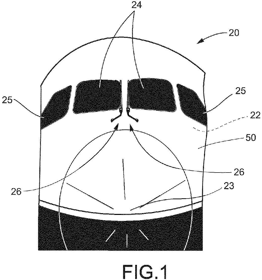
- FIG. 1 illustrates an aircraft 20 defining an interior cabin 22 and a nose 23.
- An array of windshields 24 and side windows 25 is provided at the nose 23 and a pair of wiper assemblies 26 is provided adjacent two of the windshields 24 located near a center of the aircraft 20.
- Each wiper assembly 26 includes a wiper arm 28 coupled to a rotating shaft 30 for pivoting the wiper assembly 26 and a wiper blade 32 coupled to the wiper arm 28 and configured to engage an exterior of the windshield ( FIG. 2 ).
- each wiper arm 28 includes a first connection end 34 for coupling to the rotating shaft 30 and a second connection end 36 configured to secure a wiper blade 32.
- Each wiper arm 28 further includes a substantially linear arm portion 38, extending along an arm axis 40, and an arcuate transition portion 42 between the first and second connection ends 34, 36.
- the arm portion 38 may define an arm length 44 as measured along the arm axis 40 ( FIG. 3 ).
- each wiper arm 28 may define an arm exterior surface 46 having a generally oval cross-sectional shape.
- the arm exterior surface 46 further may have an inward portion 48 oriented toward an outboard side 50 of the aircraft 20, and an outward portion 52 oriented away from the outboard side 50 of the aircraft 20.
- FIG. 4 also illustrates an air flow 54 passing over the arm portion 38 from an upstream end 56 to a downstream end 58.
- the air flow 54 creates includes a boundary layer 60 adjacent to the inward and outward portions 48, 52 of the exterior surface 46.
- An upstream part of the boundary layer 60 generally conforms to the shape of the exterior surface 46.
- the boundary layer 60 As it traverses the arm portion 38, the boundary layer 60 generally loses speed and may transition from laminar to turbulent flow.
- the boundary layer 60 leaves the exterior surface 46, which is known in the industry as boundary layer separation. This is due to the blunt shape of the arm cross-section 46.
- a bead 70 may be provided on the arm portion 38 to mitigate or eliminate the potential for noise due to vortex shedding. As best shown in FIGS. 3 and 4 , the bead 70 extends outwardly from the arm exterior surface 46 and defines a bead exterior surface 72 having an arcuate shape. In the illustrated embodiment, the bead exterior surface 72 has a semi-circular shape; however other arcuate or non-arcuate (i.e., linear or sharp) forms may be used.
- the bead 70 is sized sufficiently to trigger transition to turbulence and delay separation of the boundary layer 60 from the associated portion of the arm exterior surface 46, thereby preventing coherent oscillatory shedding of vortices from the arm portion 38.
- the bead 70 may be oriented and have a length configured to delay separation of the boundary layer 60 from the exterior surface 46.
- the bead 70 may extend linearly along a bead axis 74, however non-linear beads may also be used.
- a discontinuous bead such as a row of discrete bumps of the same height, may alternatively be used.
- the bead axis 74 may be substantially parallel (i.e., within ten degrees of parallel) to the arm axis 40.
- the bead 70 may also have a bead length 76 measured along the bead axis 74.
- the bead length 76 may be at least 50% of the arm length 44.
- the bead length 76 may be at least 70% of the arm length 44.
- the bead length 76 may be at least 80% of the arm length 44. Without being bound by theory, applicants believe that a longer bead length 76 relative to the arm length 44 increases the ability of the bead 70 to delay separation of the boundary layer 60.
- the bead 70 may be sized sufficiently to delay separation of the boundary layer 60 from the exterior surface 46.
- the bead exterior surface 72 projects outwardly from the arm exterior surface 46 by a bead height 78, while the arm portion 38 has an arm width 79.
- the bead height 78 may be selected relative to the arm width 79 to ensure delay of boundary layer separation.
- a bead height ratio which is a ratio of the bead height 78 to the arm width 79, may be used to size the bead 70. In some embodiments, the bead height ratio is approximately 1 to 5%.
- the bead height 78 may be approximately 0.05 inches while the arm width may be approximately 1.25 inches, and therefore the bead height ratio for this embodiment is approximately 4%.
- the bead exterior surface 72 may have a distal half 80 farthest from the exterior surface 46 of the arm portion 38, wherein each point of the distal half 80 is located a radius distance from the bead axis 74. In some embodiments, the radius distance may be approximately 0.025 inches.
- the bead 70 may be located at various locations along the arm exterior surface 46. As shown in FIG. 4 , for example, the bead 70 is located on the inward portion 48 of the exterior surface 46 and nearer an upstream end of the arm portion 38. Alternatively, the bead 70 may be located elsewhere in the inward portion 48 of the exterior surface 46, or even in the outward portion 52 of the exterior surface 46, as long as the bead 70 is not located at the extreme upstream or downstream ends of the arm exterior surface 46.
- the arm portion 38 may be provided with a second bead 82.
- the second bead 82 may be sized, oriented, and configured similar to the bead 70, however it may be located on the opposite side of the arm portion 38.
- the bead 70 may be located in the inward portion 48 of the arm exterior surface 46, while the second bead 82 may be located in the outward portion 52 of the arm exterior surface 46. In this way, boundary layer separation may be delayed on both sides of the arm portion 38.
- this alternative embodiment is shown in FIG. 4 , it will be appreciated that a single bead 70 has been found to adequately reduce noise due to vortex shedding, and may provide a more advantageous appearance when located on the inward portion 48 of the arm exterior surface 46.
- the bead 70 is formed integrally with the arm portion 38, such as by molding the bead 70 at the same time as the arm portion 38.
- the bead 70 may be retrofit onto an existing arm portion 38 that was not originally provided with a bead.
- the bead 70 may be coupled to the arm portion 38 using adhesive bonding, mechanical connection, or other coupling means.
- bead 70 is described above in connection with the wiper arm 28, it will be appreciated that the bead 70 may be provided on other components that are susceptible to inducing vortex shedding when exposed to a fluid flow.
- a method may be provided of reducing vortex shedding produced by an air flow passing over a component having an arm disposed on an outboard side of a vehicle, such as the arm portion 38 of the wiper arm 28 provided on the aircraft 20.
- the method may include positioning the bead 70 along the exterior surface 46 of the arm, the bead defining a bead exterior surface 72 extending outwardly from the arm exterior surface 46 and having an arcuate profile.
- the bead 70 may be sized sufficiently to engage the boundary layer 60 of the air flow 54, so that when directing the air flow 54 over the arm exterior surface 46 and bead 70 may delay boundary layer separation from the arm.
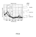
- FIG. 5 is a graph plotting the sound pressure level (in decibels) against a range of noise frequencies (in Hertz).
- the graph includes three lines.
- a first line 90 shows a baseline profile for an arm portion having no bead, as schematically illustrated in FIG. 5 and identified by reference numeral 92.
- the first line 90 includes a spike 94 in noise level near a noise frequency of 2000 Hertz. Applicants believe this spike is associated with the noise observed inside the aircraft cabin 22.
- the spike frequency of approximately 2000 Hertz was obtained during laboratory testing. During actual flight testing, the noise spike was observed at approximately 4000 Hertz. The difference between the laboratory and flight testing is due to the air flow velocity in the lab test being approximately 1 ⁇ 2 of the velocity in flight.
- a second line 96 illustrates a noise profile associated with an arm portion having a single bead positioned on an inward portion of the exterior surface, as schematically illustrated in FIG. 5 and identified by reference numeral 98.
- a third line 100 illustrates a noise profile associated with an arm portion having two beads positioned on opposite sides of the exterior surface, as schematically illustrated in FIG. 5 and identified by reference numeral 102. Both the second and third lines 96, 100 show a reduced noise level at both the 2000 and 4000 Hertz frequencies, thereby indicating that the noise may be attenuated to a desirable level.
Landscapes
- Engineering & Computer Science (AREA)
- Mechanical Engineering (AREA)
- Physics & Mathematics (AREA)
- Fluid Mechanics (AREA)
- Quality & Reliability (AREA)
- Aviation & Aerospace Engineering (AREA)
- Body Structure For Vehicles (AREA)
Abstract
Description
- The present disclosure generally relates to external components or appendages attached to streamlined vehicles and, more specifically, to vehicle components modified to reduce the shedding of vortices they may create when subjected to air flows, as well as associated vibrations and noise.
- Bodies that encounter fluid flow may cause vortex-induced vibration. More specifically, air or water flowing at sufficient velocity past a cylindrical, near-cylindrical or in general bluff body may create vortices downstream of the body. The vortices may detach periodically from the two sides of the body - a phenomenon called "vortex shedding." Because the vortices have reduced pressure in their core, forces are created during vortex shedding that are directed toward the locations of the vortices. These forces can cause the body itself to oscillate, which is common for flexible antennas, or apply oscillatory loads to other parts of the vehicle, which is common for the skin or windows of the vehicle. If the frequency of the vortex shedding matches the resonance frequency of the body, the body may resonate at harmonic oscillations. Additionally, the pressure waves associated with the vortices may produce unwanted noise that may be observed inside the cabin.
- In the field of aviation, certain parts of an aircraft such as probes, antennas and air inlets may be disposed outboard of the cabin and therefore exposed to a rapid air flow. A windshield wiper assembly, for example, may include a wiper arm that is positioned to engage a wiper blade with the exterior of a windshield. The wiper arm may include an arm portion that is disposed outboard of the cabin and therefore subject to the air flow generated around a nose of the aircraft during travel. On some aircraft and at certain airspeeds, noise may be observed in the cabin that may appear to be emanating from the vicinity of the wiper arms and therefore may be attributed to vortex shedding from these arms. In some instances the noise may be attenuated by reinstallation of the same wiper arm or replacement with a new wiper arm, however a reliable solution has not heretofore been proposed. A test flight with the wipers removed showed that the noise was eliminated, which confirmed the role of the wipers in creating the noise.
- In accordance with one aspect of the present disclosure, a component is disposed on an external side of a vehicle and positioned to directly engage an air flow while the vehicle is traveling. The component includes an arm coupled to the vehicle and having an arm exterior surface, the arm extending along an arm axis and defining an arm length. A bead extends outwardly from the arm exterior surface and defines a bead exterior surface, the bead being configured to engage a boundary layer of the air flow.
- In accordance with another aspect of the present disclosure, a method is provided of reducing vortex shedding produced by an air flow passing over a component having an arm disposed on an outboard side of a vehicle. The method comprises positioning a bead along an exterior surface of the arm, the bead defining a bead exterior surface extending outwardly from the arm exterior surface, and using an appropriate size for the bead to engage a boundary layer of the air flow.
- In accordance with a further aspect of the present disclosure, a wiper arm is disposed on an outside of an aircraft and positioned to directly engage an air flow while the aircraft is traveling. The wiper arm includes an arm portion coupled to the aircraft and having an arm exterior surface, the arm portion extending along an arm axis and defining an arm length. A bead extends outwardly from the arm exterior surface and defines a bead exterior surface having an arcuate profile, the bead having a size sufficient to engage a boundary layer of the air flow. A wiper blade is coupled to the arm portion.
- In another aspect of the disclosure that may be combined with any of these aspects, the bead may extend substantially parallel to the arm axis and defines a bead length that is at least approximately 50% of the arm length.
- In another aspect of the disclosure that may be combined with any of these aspects, the bead has a height, the arm has a width, and a ratio of bead height to arm width which is approximately 1 to 5%.
- In another aspect of the disclosure that may be combined with any of these aspects, the bead may extend along a bead axis, and in which a distal half of the bead exterior surface is located a radius distance from the bead axis.
- In another aspect of the disclosure that may be combined with any of these aspects, the radius distance may be approximately 0.025 inches.
- In another aspect of the disclosure that may be combined with any of these aspects, the arm exterior surface may include an inward portion oriented toward the outboard side of the vehicle and an outward portion oriented away from the outboard side of the vehicle, and the bead may be located in the inward portion of the arm exterior surface.
- In another aspect of the disclosure that may be combined with any of these aspects, a second bead may extend outwardly from the outward portion of the arm exterior surface and define a second bead exterior surface.
- In another aspect of the disclosure that may be combined with any of these aspects, the bead may define first and second ends, and the bead exterior surface may extend continuously from the first end to the second end.
- In another aspect of the disclosure that may be combined with any of these aspects, the bead may be formed integrally with the arm.
- The invention can involve a component disposed on an external side of a vehicle and positioned to directly engage an air flow while the vehicle is traveling, the component may include an arm coupled to the vehicle and having an arm exterior surface, the arm extending along an arm axis and defining an arm length; and a bead extending outwardly from the arm exterior surface and defining a bead exterior surface, the bead being configured to engage a boundary layer of the air flow. The bead may extend substantially parallel to the arm axis and defines a bead length that is at least approximately 50% of the arm length. The bead may have a height, the arm has a width, and a ratio of bead height to arm width is approximately 1 to 5%. The bead may extend along a bead axis, and in which a distal half of the bead exterior surface is located a radius distance from the bead axis. Each of these characteristics can enhance the performance and reliability of the bead. The radius distance may be approximately 0.025 inches to improve the operation. The arm exterior surface may include an inward portion oriented toward the outboard side of the vehicle and an outward portion oriented away from the outboard side of the vehicle, and in which the bead is located in the inward portion of the arm exterior surface. The component may also include a second bead extending outwardly from the outward portion of the arm exterior surface and defining a second bead exterior surface configured to engage the boundary layer of the air flow. The component may include a bead that defines first and second ends, and in which the bead exterior surface extends continuously from the first end to the second end. The bead may be formed integrally with the arm.
- The invention can involve a method of reducing vortex shedding produced by an air flow passing over a component having an arm disposed on an outboard side of a vehicle that may include positioning a bead along an exterior surface of the arm, the bead defining a bead exterior surface extending outwardly from the arm exterior surface; and using an appropriate size for the bead to engage a boundary layer of the air flow. The arm exterior surface can include an inward portion oriented toward the outboard side of the vehicle and an outward portion oriented away from the outboard side of the vehicle, the method further comprising locating the bead in the inward portion of the arm exterior surface. The method may also include positioning a second bead along the exterior surface of the arm, the second bead defining a second bead exterior surface extending outwardly from the outward portion of the arm exterior surface and having an appropriate size for the second bead to engage the boundary layer of the air flow. The bead may be integrally formed with the arm. The method may also include forming the bead independently of the arm; and bonding the bead to the arm.
- The invention can involve a wiper arm disposed on an outside of an aircraft and positioned to directly engage an air flow while the aircraft is traveling. The wiper arm may include an arm portion coupled to the aircraft and having an arm exterior surface, the arm portion extending along an arm axis and defining an arm length; a bead extending outwardly from the arm exterior surface and defining a bead exterior surface having an arcuate profile, the bead having a size sufficient to engage a boundary layer of the air flow; and a wiper blade coupled to the arm portion. The bead may extend substantially parallel to the arm axis and defines a bead length that is at least approximately 50% of the arm length. The bead may extend along a bead axis, in which a distal half of the bead exterior surface is located a radius distance from the bead axis, and in which the radius distance is approximately 0.025 inches. The arm exterior surface may include an inward portion oriented toward the outboard side of the aircraft and an outward portion oriented away from the outboard side of the aircraft, and in which the bead is located in the inward portion of the arm exterior surface. The wiper arm may also include a second bead extending outwardly from the outward portion of the arm exterior surface and defining a second bead exterior surface having an arcuate profile, the second bead having a size sufficient to engage the boundary layer of the air flow. The bead may be formed integrally with the arm portion.
- The features, functions, and advantages that have been discussed can be achieved independently in various embodiments or may be combined in yet other embodiments further details of which can be seen with reference to the following description and drawings.
-
-
FIG. 1 is a front view of an aircraft including external components in the form of windshield wiper arms. -
FIG. 2 is a perspective view of the windshield wiper arms ofFIG. 1 . -
FIG. 3 is an enlarged perspective view of a lower portion of the wiper arm shown inFIGS. 1 and 2 showing a bead for reducing noise generated by the wiper arm. -
FIG. 4 is a side elevation view, in cross-section, of the lower portion of the wiper arm ofFIG. 3 , with an exemplary air flow directed over the arm portion. -
FIG. 5 is a graph illustrating the sound pressure level across a range of sound frequencies for a baseline wiper arm, a single bead wiper arm embodiment, and a double bead wiper arm embodiment. - It should be understood that the drawings are not necessarily drawn to scale and that the disclosed embodiments are sometimes illustrated schematically. It is to be further appreciated that the following detailed description is merely exemplary in nature and is not intended to limit the invention or the application and uses thereof. Hence, although the present disclosure is, for convenience of explanation, depicted and described as certain illustrative embodiments, it will be appreciated that it can be implemented in various other types of embodiments and in various other systems and environments.
- The following detailed description is of the best currently contemplated modes of carrying out the invention. The description is not to be taken in a limiting sense, but is made merely for the purpose of illustrating the general principles of the invention, since the scope of the invention is best defined by the appended claims.
- For ease of understanding the orientation in the drawings, the terms "inside", "inboard", and "interior" shall refer to a direction oriented from the viewpoint of a person standing within the cabin of the aircraft, and the terms "outside", "outboard", and "exterior" shall refer to a direction oriented from the viewpoint of a person outside of the cabin observing the aircraft.
-
FIG. 1 illustrates anaircraft 20 defining aninterior cabin 22 and anose 23. An array ofwindshields 24 andside windows 25 is provided at thenose 23 and a pair ofwiper assemblies 26 is provided adjacent two of thewindshields 24 located near a center of theaircraft 20. Eachwiper assembly 26 includes awiper arm 28 coupled to arotating shaft 30 for pivoting thewiper assembly 26 and awiper blade 32 coupled to thewiper arm 28 and configured to engage an exterior of the windshield (FIG. 2 ). - The
wiper arms 28 are shown in greater detail inFIG. 2 . In the illustrated embodiment, eachwiper arm 28 includes afirst connection end 34 for coupling to therotating shaft 30 and a second connection end 36 configured to secure awiper blade 32. Eachwiper arm 28 further includes a substantiallylinear arm portion 38, extending along anarm axis 40, and anarcuate transition portion 42 between the first and second connection ends 34, 36. Thearm portion 38 may define anarm length 44 as measured along the arm axis 40 (FIG. 3 ). - As best understood with reference to
FIGS. 3 and 4 , thearm portion 38 of eachwiper arm 28 may define anarm exterior surface 46 having a generally oval cross-sectional shape. Thearm exterior surface 46 further may have aninward portion 48 oriented toward anoutboard side 50 of theaircraft 20, and anoutward portion 52 oriented away from theoutboard side 50 of theaircraft 20. -
FIG. 4 also illustrates anair flow 54 passing over thearm portion 38 from anupstream end 56 to adownstream end 58. In the illustrated embodiment, theair flow 54 creates includes aboundary layer 60 adjacent to the inward andoutward portions exterior surface 46. An upstream part of theboundary layer 60 generally conforms to the shape of theexterior surface 46. As it traverses thearm portion 38, theboundary layer 60 generally loses speed and may transition from laminar to turbulent flow. Ultimately, theboundary layer 60 leaves theexterior surface 46, which is known in the industry as boundary layer separation. This is due to the blunt shape of thearm cross-section 46. When the vortices generated by boundary layer separation oscillate coherently, that is, are shed from opposite sides of the component in a repeating alternating pattern with the distance between them close to the width of thewiper arm 38, they can produce pressure waves that may observed as noise inside thecabin 22. - A
bead 70 may be provided on thearm portion 38 to mitigate or eliminate the potential for noise due to vortex shedding. As best shown inFIGS. 3 and 4 , thebead 70 extends outwardly from thearm exterior surface 46 and defines abead exterior surface 72 having an arcuate shape. In the illustrated embodiment, thebead exterior surface 72 has a semi-circular shape; however other arcuate or non-arcuate (i.e., linear or sharp) forms may be used. Thebead 70 is sized sufficiently to trigger transition to turbulence and delay separation of theboundary layer 60 from the associated portion of thearm exterior surface 46, thereby preventing coherent oscillatory shedding of vortices from thearm portion 38. - More specifically, the
bead 70 may be oriented and have a length configured to delay separation of theboundary layer 60 from theexterior surface 46. In the embodiment illustrated inFIGS. 3 and 4 , for example, thebead 70 may extend linearly along abead axis 74, however non-linear beads may also be used. Additionally, while the bead ofFIGS. 3 and 4 extends continuously between its ends, a discontinuous bead, such as a row of discrete bumps of the same height, may alternatively be used. In some applications, thebead axis 74 may be substantially parallel (i.e., within ten degrees of parallel) to thearm axis 40. Thebead 70 may also have abead length 76 measured along thebead axis 74. In some embodiments, thebead length 76 may be at least 50% of thearm length 44. In other embodiments, thebead length 76 may be at least 70% of thearm length 44. In still other embodiments, thebead length 76 may be at least 80% of thearm length 44. Without being bound by theory, applicants believe that alonger bead length 76 relative to thearm length 44 increases the ability of thebead 70 to delay separation of theboundary layer 60. - Additionally, the
bead 70 may be sized sufficiently to delay separation of theboundary layer 60 from theexterior surface 46. As best shown inFIG. 4 , thebead exterior surface 72 projects outwardly from thearm exterior surface 46 by abead height 78, while thearm portion 38 has anarm width 79. Thebead height 78 may be selected relative to thearm width 79 to ensure delay of boundary layer separation. For example, a bead height ratio, which is a ratio of thebead height 78 to thearm width 79, may be used to size thebead 70. In some embodiments, the bead height ratio is approximately 1 to 5%. In a particular embodiment, thebead height 78 may be approximately 0.05 inches while the arm width may be approximately 1.25 inches, and therefore the bead height ratio for this embodiment is approximately 4%. Additionally, thebead exterior surface 72 may have adistal half 80 farthest from theexterior surface 46 of thearm portion 38, wherein each point of thedistal half 80 is located a radius distance from thebead axis 74. In some embodiments, the radius distance may be approximately 0.025 inches. - The
bead 70 may be located at various locations along thearm exterior surface 46. As shown inFIG. 4 , for example, thebead 70 is located on theinward portion 48 of theexterior surface 46 and nearer an upstream end of thearm portion 38. Alternatively, thebead 70 may be located elsewhere in theinward portion 48 of theexterior surface 46, or even in theoutward portion 52 of theexterior surface 46, as long as thebead 70 is not located at the extreme upstream or downstream ends of thearm exterior surface 46. - In an alternative embodiment, the
arm portion 38 may be provided with asecond bead 82. As shown inFIG. 4 , thesecond bead 82 may be sized, oriented, and configured similar to thebead 70, however it may be located on the opposite side of thearm portion 38. For example, thebead 70 may be located in theinward portion 48 of thearm exterior surface 46, while thesecond bead 82 may be located in theoutward portion 52 of thearm exterior surface 46. In this way, boundary layer separation may be delayed on both sides of thearm portion 38. While this alternative embodiment is shown inFIG. 4 , it will be appreciated that asingle bead 70 has been found to adequately reduce noise due to vortex shedding, and may provide a more advantageous appearance when located on theinward portion 48 of thearm exterior surface 46. - Various construction methods may be employed to provide the
bead 70 on thearm portion 38. In the illustrated embodiments, thebead 70 is formed integrally with thearm portion 38, such as by molding thebead 70 at the same time as thearm portion 38. Alternatively, thebead 70 may be retrofit onto an existingarm portion 38 that was not originally provided with a bead. For example, thebead 70 may be coupled to thearm portion 38 using adhesive bonding, mechanical connection, or other coupling means. - While the
bead 70 is described above in connection with thewiper arm 28, it will be appreciated that thebead 70 may be provided on other components that are susceptible to inducing vortex shedding when exposed to a fluid flow. - Additionally, a method may be provided of reducing vortex shedding produced by an air flow passing over a component having an arm disposed on an outboard side of a vehicle, such as the
arm portion 38 of thewiper arm 28 provided on theaircraft 20. The method may include positioning thebead 70 along theexterior surface 46 of the arm, the bead defining abead exterior surface 72 extending outwardly from thearm exterior surface 46 and having an arcuate profile. Thebead 70 may be sized sufficiently to engage theboundary layer 60 of theair flow 54, so that when directing theair flow 54 over thearm exterior surface 46 andbead 70 may delay boundary layer separation from the arm. -
FIG. 5 is a graph plotting the sound pressure level (in decibels) against a range of noise frequencies (in Hertz). The graph includes three lines. Afirst line 90 shows a baseline profile for an arm portion having no bead, as schematically illustrated inFIG. 5 and identified byreference numeral 92. Thefirst line 90 includes aspike 94 in noise level near a noise frequency of 2000 Hertz. Applicants believe this spike is associated with the noise observed inside theaircraft cabin 22. The spike frequency of approximately 2000 Hertz was obtained during laboratory testing. During actual flight testing, the noise spike was observed at approximately 4000 Hertz. The difference between the laboratory and flight testing is due to the air flow velocity in the lab test being approximately ½ of the velocity in flight. The lab test air velocity was selected because the value of the kinematic viscosity of the air in the lab is about ½ of the value in flight, so this arrangement produced the same Reynolds number for the two flows. The Reynolds number controls the transition to turbulence, and therefore should match between the two situations. The spectrum for the baseline geometry also has aharmonic peak 95 at twice the fundamental frequency, and therefore near 4000 Hertz. Asecond line 96 illustrates a noise profile associated with an arm portion having a single bead positioned on an inward portion of the exterior surface, as schematically illustrated inFIG. 5 and identified byreference numeral 98. Additionally, athird line 100 illustrates a noise profile associated with an arm portion having two beads positioned on opposite sides of the exterior surface, as schematically illustrated inFIG. 5 and identified byreference numeral 102. Both the second andthird lines - It will be appreciated that the foregoing description provides examples of the disclosed apparatus and methods. However, it is contemplated that other implementations of the disclosure may differ in detail from the foregoing examples. All references to the disclosure or examples thereof are intended to reference the particular example being discussed at that point and are not intended to imply any limitation as to the scope of the disclosure more generally. All language of distinction and disparagement with respect to certain features is intended to indicate a lack of preference for those features, but not to exclude such from the scope of the disclosure entirely unless otherwise indicated.
- Recitation of ranges of values herein are merely intended to serve as a shorthand method of referring individually to each separate value falling within the range, unless otherwise indicated herein, and each separate value is incorporated into the specification as if it were individually recited herein. All methods described herein can be performed in any suitable order unless otherwise indicated herein or otherwise clearly contradicted by context.
- Accordingly, this disclosure includes all modifications and equivalents of the subject matter recited in the claims appended hereto as permitted by applicable law. Moreover, any combination of the above-described elements in all possible variations thereof is encompassed by the disclosure unless otherwise indicated herein or otherwise clearly contradicted by context.
Claims (14)
- A component disposed on an external side of a vehicle (20) and positioned to directly engage an air flow while the vehicle is traveling, the component comprising:an arm (28) coupled to the vehicle and having an arm exterior surface (46), the arm extending along an arm axis and defining an arm length; anda bead (70) extending outwardly from the arm exterior surface (46) and defining a bead exterior surface (72), the bead (70) being configured to engage a boundary layer (60) of the air flow (54).
- The component of claim 1, in which the bead (70) extends substantially parallel to the arm axis and defines a bead length (76) that is at least approximately 50% of the arm length.
- The component of claim 1 or 2, in which the bead (70) has a height (78), the arm has a width (79), and a ratio of bead height (78) to arm width (79) is approximately 1 to 5%.
- The component of any of claims 1 to 3, in which the bead (70) extends along a bead axis, and in which a distal half of the bead exterior surface is located a radius distance from the bead axis.
- The component of claim 4, in which the radius distance is approximately 0.025 inches.
- The component of any of claims 1 to 5, in which the arm exterior surface includes an inward portion (48) oriented toward the outboard side (50) of the vehicle and an outward portion (52) oriented away from the outboard side (50) of the vehicle, and in which the bead (70) is located in the inward portion (48) of the arm exterior surface (46).
- The component of claim 6, further comprising a second bead (82) extending outwardly from the outward portion of the arm exterior surface (46) and defining a second bead exterior surface configured to engage the boundary layer (60) of the air flow (54).
- The component of any of claims 1 to 7, in which the bead (70) defines first and second ends, and in which the bead exterior surface (72) extends continuously from the first end to the second end.
- The component of any of claims 1 to 8, in which the bead (70) is formed integrally with the arm (28).
- A method of reducing vortex shedding produced by an air flow passing over a component having an arm (28) disposed on an outboard side of a vehicle (20), the method comprising:positioning a bead (70) along an exterior surface (46) of the arm (28), the bead (70) defining a bead exterior surface (72) extending outwardly from the arm exterior surface (46); andusing an appropriate size for the bead (70) to engage a boundary layer (60) of the air flow (54).
- The method of claim 10, in which the arm exterior surface (46) includes an inward portion (48) oriented toward the outboard side (50) of the vehicle and an outward portion (52) oriented away from the outboard side (50) of the vehicle, the method further comprising locating the bead (70) in the inward portion (48) of the arm exterior surface (46).
- The method of claim 11, further comprising positioning a second bead (82) along the exterior surface (46) of the arm (28), the second bead (82) defining a second bead exterior surface extending outwardly from the outward portion (52) of the arm exterior surface (46) and having an appropriate size for the second bead (82) to engage the boundary layer (60) of the air flow (54).
- The method of any of claims 10 to 12, further comprising forming the bead (70) integrally with the arm (28).
- The method of any of claims 10 to 12, further comprising:forming the bead (70) independently of the arm (28); andbonding the bead (70) to the arm (28).
Applications Claiming Priority (1)
| Application Number | Priority Date | Filing Date | Title |
|---|---|---|---|
| US14/501,375 US9827952B2 (en) | 2014-09-30 | 2014-09-30 | Vehicle external component having reduced vortex shedding |
Publications (2)
| Publication Number | Publication Date |
|---|---|
| EP3002163A1 true EP3002163A1 (en) | 2016-04-06 |
| EP3002163B1 EP3002163B1 (en) | 2019-03-13 |
Family
ID=54065786
Family Applications (1)
| Application Number | Title | Priority Date | Filing Date |
|---|---|---|---|
| EP15184204.4A Active EP3002163B1 (en) | 2014-09-30 | 2015-09-08 | Aircraft windshield wiper arm having reduced vortex shedding |
Country Status (4)
| Country | Link |
|---|---|
| US (1) | US9827952B2 (en) |
| EP (1) | EP3002163B1 (en) |
| CN (1) | CN105460208B (en) |
| CA (1) | CA2897386C (en) |
Families Citing this family (2)
| Publication number | Priority date | Publication date | Assignee | Title |
|---|---|---|---|---|
| SG11202000427RA (en) * | 2017-07-17 | 2020-02-27 | Lubrizol Corp | Low zinc lubricant composition |
| WO2019018329A1 (en) * | 2017-07-17 | 2019-01-24 | The Lubrizol Corporation | Low dispersant lubricant composition |
Citations (5)
| Publication number | Priority date | Publication date | Assignee | Title |
|---|---|---|---|---|
| DE3424729A1 (en) * | 1984-07-05 | 1986-02-06 | SWF Auto-Electric GmbH, 7120 Bietigheim-Bissingen | Wiper lever, in particular for the window wiper systems of motor vehicles |
| FR2632897A1 (en) * | 1988-06-20 | 1989-12-22 | Journee Paul Sa | Windscreen wiper arm for a motor vehicle windscreen wiper |
| FR2785248A1 (en) * | 1998-10-28 | 2000-05-05 | Valeo Systemes Dessuyage | WINDSCREEN WIPER ARM CONFORMING TO AERODYNAMIC DEFLECTOR |
| US20020020034A1 (en) * | 2000-06-01 | 2002-02-21 | Kwang-Je Choi | Windshield wiper arm |
| JP2006117007A (en) * | 2004-10-19 | 2006-05-11 | Nippon Wiper Blade Co Ltd | Joint member |
Family Cites Families (18)
| Publication number | Priority date | Publication date | Assignee | Title |
|---|---|---|---|---|
| DE3007352A1 (en) * | 1980-02-27 | 1981-09-10 | Robert Bosch Gmbh, 7000 Stuttgart | WIPING DEVICE FOR WINDOWS OF MOTOR VEHICLES |
| JPS57928A (en) * | 1980-06-03 | 1982-01-06 | Nippon Soken Inc | Wind sealded wiper |
| US4782547A (en) * | 1987-01-29 | 1988-11-08 | The Anderson Company Of Indiana | Attachment structure |
| JPH0225354U (en) * | 1988-08-09 | 1990-02-20 | ||
| FR2642714B1 (en) * | 1989-02-08 | 1991-03-29 | Journee Paul | WINDSCREEN WIPER WITH BUILT-IN DEFLECTOR |
| US5402964A (en) | 1993-10-25 | 1995-04-04 | Wygnanski; Israel J. | Interference with vortex formation and control of fluid flow to reduce noise and change flow stability |
| US6019549A (en) | 1996-06-11 | 2000-02-01 | Corrosion Control International Llc | Vortex shedding strake wraps for submerged pilings and pipes |
| US6100499A (en) * | 1997-04-10 | 2000-08-08 | Davila, Sr.; Richard A. | Heated and lighted windshield wiper assembly |
| DE19818723B4 (en) * | 1997-04-28 | 2009-10-22 | Toyota Jidosha Kabushiki Kaisha, Toyota-shi | Windshield wipers |
| JP3218211B2 (en) * | 1997-12-22 | 2001-10-15 | アスモ株式会社 | Wiper arm |
| DE50011626D1 (en) * | 1999-06-26 | 2005-12-22 | Bosch Gmbh Robert | WINDSHIELD WIPERS |
| US20040045116A1 (en) * | 2002-09-11 | 2004-03-11 | Tibor Siklosi | Windshield wiper having a single-rail spline |
| US6833682B2 (en) * | 2002-10-28 | 2004-12-21 | Valeo Electrical Systems, Inc. | Windshield wiper system with tubular drive arm and cavity |
| US7967253B2 (en) | 2004-01-16 | 2011-06-28 | The Boeing Company | Antenna fairing and method |
| US20080289137A1 (en) * | 2007-05-25 | 2008-11-27 | Michael Peter Ciaccio | Aerodynamic windshield wiper arm |
| FR2938807B1 (en) * | 2008-11-24 | 2012-04-06 | Airbus France | WINDSCREEN WIPERS FOR FRONT VEHICLE WINDOW. |
| US9009909B2 (en) * | 2011-11-15 | 2015-04-21 | Dongguan Hongyi Wiper Co., Ltd. | Windshield wiper |
| US8770894B1 (en) | 2011-12-27 | 2014-07-08 | VIV Solutions LLC | Helical strakes with molded in stand-offs |
-
2014
- 2014-09-30 US US14/501,375 patent/US9827952B2/en active Active
-
2015
- 2015-07-14 CA CA2897386A patent/CA2897386C/en active Active
- 2015-09-08 EP EP15184204.4A patent/EP3002163B1/en active Active
- 2015-09-28 CN CN201510626551.3A patent/CN105460208B/en active Active
Patent Citations (5)
| Publication number | Priority date | Publication date | Assignee | Title |
|---|---|---|---|---|
| DE3424729A1 (en) * | 1984-07-05 | 1986-02-06 | SWF Auto-Electric GmbH, 7120 Bietigheim-Bissingen | Wiper lever, in particular for the window wiper systems of motor vehicles |
| FR2632897A1 (en) * | 1988-06-20 | 1989-12-22 | Journee Paul Sa | Windscreen wiper arm for a motor vehicle windscreen wiper |
| FR2785248A1 (en) * | 1998-10-28 | 2000-05-05 | Valeo Systemes Dessuyage | WINDSCREEN WIPER ARM CONFORMING TO AERODYNAMIC DEFLECTOR |
| US20020020034A1 (en) * | 2000-06-01 | 2002-02-21 | Kwang-Je Choi | Windshield wiper arm |
| JP2006117007A (en) * | 2004-10-19 | 2006-05-11 | Nippon Wiper Blade Co Ltd | Joint member |
Also Published As
| Publication number | Publication date |
|---|---|
| CN105460208B (en) | 2020-02-11 |
| US20160090065A1 (en) | 2016-03-31 |
| CA2897386C (en) | 2018-08-07 |
| CA2897386A1 (en) | 2016-03-30 |
| EP3002163B1 (en) | 2019-03-13 |
| US9827952B2 (en) | 2017-11-28 |
| CN105460208A (en) | 2016-04-06 |
Similar Documents
| Publication | Publication Date | Title |
|---|---|---|
| US8256702B2 (en) | Aircraft landing gear provided with at least one noise reducing means | |
| US9545997B2 (en) | Wingtip extension for reducing wake vortices of aircraft | |
| US11577823B2 (en) | Noise reduction apparatus, aircraft, and noise reduction method | |
| JP6254437B2 (en) | Variable width aerodynamic device | |
| US9371734B2 (en) | Turbine blade | |
| EP2824033A1 (en) | Apparatus for acoustic resonance mitigation | |
| EP3002163B1 (en) | Aircraft windshield wiper arm having reduced vortex shedding | |
| US10024167B2 (en) | Turbine blade | |
| GB2506194A (en) | Patch for reducing aerodynamically generated aircraft noise | |
| EP2955101A1 (en) | Ventilated drainage system | |
| Wiggen | Experimental results for vortex dominated flow at a Lambda-wing with a round leading edge in steady flow | |
| US8640989B2 (en) | Speed brake for aircraft | |
| Grager et al. | Low Reynolds Number Airfoil Stall Suppression with Dynamic Roughness | |
| EP3470329B9 (en) | Wing and aircraft | |
| EP3348470B1 (en) | Airplane or vehicle with configuration of a t junction of a flow obstacle on a wall bounding a flow | |
| Nili-Ahmadabadi et al. | PIV Measurement of Riblet Effects on Flow Characteristics of a Delta Wing | |
| WO2014109670A2 (en) | Method and apparatus for achieving laminar flow of gas or liquid near cutting edges | |
| Raghav et al. | A Study of 3-Dimensional Reattachment on Rotor Blades After Dynamic Stall | |
| Pfenninger et al. | THE FRONT ATTACHMENT LINE OF A 45 SWEPT FLAT-NOSED WING WITH AND | |
| FR3013324A1 (en) | AIRCRAFT ANTENNA | |
| KR20100094111A (en) | Airfoil |
Legal Events
| Date | Code | Title | Description |
|---|---|---|---|
| PUAI | Public reference made under article 153(3) epc to a published international application that has entered the european phase |
Free format text: ORIGINAL CODE: 0009012 |
|
| AK | Designated contracting states |
Kind code of ref document: A1 Designated state(s): AL AT BE BG CH CY CZ DE DK EE ES FI FR GB GR HR HU IE IS IT LI LT LU LV MC MK MT NL NO PL PT RO RS SE SI SK SM TR |
|
| AX | Request for extension of the european patent |
Extension state: BA ME |
|
| 17P | Request for examination filed |
Effective date: 20160923 |
|
| RBV | Designated contracting states (corrected) |
Designated state(s): AL AT BE BG CH CY CZ DE DK EE ES FI FR GB GR HR HU IE IS IT LI LT LU LV MC MK MT NL NO PL PT RO RS SE SI SK SM TR |
|
| REG | Reference to a national code |
Ref country code: DE Ref legal event code: R079 Ref document number: 602015026207 Country of ref document: DE Free format text: PREVIOUS MAIN CLASS: B60S0001040000 Ipc: B64C0001140000 |
|
| RIC1 | Information provided on ipc code assigned before grant |
Ipc: B64C 1/14 20060101AFI20180308BHEP Ipc: B60S 1/32 20060101ALI20180308BHEP Ipc: B60S 1/04 20060101ALI20180308BHEP Ipc: B60S 1/34 20060101ALI20180308BHEP |
|
| GRAP | Despatch of communication of intention to grant a patent |
Free format text: ORIGINAL CODE: EPIDOSNIGR1 |
|
| STAA | Information on the status of an ep patent application or granted ep patent |
Free format text: STATUS: GRANT OF PATENT IS INTENDED |
|
| INTG | Intention to grant announced |
Effective date: 20180508 |
|
| GRAJ | Information related to disapproval of communication of intention to grant by the applicant or resumption of examination proceedings by the epo deleted |
Free format text: ORIGINAL CODE: EPIDOSDIGR1 |
|
| STAA | Information on the status of an ep patent application or granted ep patent |
Free format text: STATUS: REQUEST FOR EXAMINATION WAS MADE |
|
| GRAP | Despatch of communication of intention to grant a patent |
Free format text: ORIGINAL CODE: EPIDOSNIGR1 |
|
| STAA | Information on the status of an ep patent application or granted ep patent |
Free format text: STATUS: GRANT OF PATENT IS INTENDED |
|
| INTC | Intention to grant announced (deleted) | ||
| INTG | Intention to grant announced |
Effective date: 20181004 |
|
| GRAS | Grant fee paid |
Free format text: ORIGINAL CODE: EPIDOSNIGR3 |
|
| GRAA | (expected) grant |
Free format text: ORIGINAL CODE: 0009210 |
|
| STAA | Information on the status of an ep patent application or granted ep patent |
Free format text: STATUS: THE PATENT HAS BEEN GRANTED |
|
| AK | Designated contracting states |
Kind code of ref document: B1 Designated state(s): AL AT BE BG CH CY CZ DE DK EE ES FI FR GB GR HR HU IE IS IT LI LT LU LV MC MK MT NL NO PL PT RO RS SE SI SK SM TR |
|
| REG | Reference to a national code |
Ref country code: GB Ref legal event code: FG4D |
|
| REG | Reference to a national code |
Ref country code: CH Ref legal event code: EP Ref country code: AT Ref legal event code: REF Ref document number: 1107354 Country of ref document: AT Kind code of ref document: T Effective date: 20190315 |
|
| REG | Reference to a national code |
Ref country code: IE Ref legal event code: FG4D |
|
| REG | Reference to a national code |
Ref country code: DE Ref legal event code: R096 Ref document number: 602015026207 Country of ref document: DE |
|
| REG | Reference to a national code |
Ref country code: NL Ref legal event code: MP Effective date: 20190313 |
|
| REG | Reference to a national code |
Ref country code: LT Ref legal event code: MG4D |
|
| PG25 | Lapsed in a contracting state [announced via postgrant information from national office to epo] |
Ref country code: FI Free format text: LAPSE BECAUSE OF FAILURE TO SUBMIT A TRANSLATION OF THE DESCRIPTION OR TO PAY THE FEE WITHIN THE PRESCRIBED TIME-LIMIT Effective date: 20190313 Ref country code: LT Free format text: LAPSE BECAUSE OF FAILURE TO SUBMIT A TRANSLATION OF THE DESCRIPTION OR TO PAY THE FEE WITHIN THE PRESCRIBED TIME-LIMIT Effective date: 20190313 Ref country code: NO Free format text: LAPSE BECAUSE OF FAILURE TO SUBMIT A TRANSLATION OF THE DESCRIPTION OR TO PAY THE FEE WITHIN THE PRESCRIBED TIME-LIMIT Effective date: 20190613 Ref country code: SE Free format text: LAPSE BECAUSE OF FAILURE TO SUBMIT A TRANSLATION OF THE DESCRIPTION OR TO PAY THE FEE WITHIN THE PRESCRIBED TIME-LIMIT Effective date: 20190313 |
|
| PG25 | Lapsed in a contracting state [announced via postgrant information from national office to epo] |
Ref country code: LV Free format text: LAPSE BECAUSE OF FAILURE TO SUBMIT A TRANSLATION OF THE DESCRIPTION OR TO PAY THE FEE WITHIN THE PRESCRIBED TIME-LIMIT Effective date: 20190313 Ref country code: RS Free format text: LAPSE BECAUSE OF FAILURE TO SUBMIT A TRANSLATION OF THE DESCRIPTION OR TO PAY THE FEE WITHIN THE PRESCRIBED TIME-LIMIT Effective date: 20190313 Ref country code: HR Free format text: LAPSE BECAUSE OF FAILURE TO SUBMIT A TRANSLATION OF THE DESCRIPTION OR TO PAY THE FEE WITHIN THE PRESCRIBED TIME-LIMIT Effective date: 20190313 Ref country code: GR Free format text: LAPSE BECAUSE OF FAILURE TO SUBMIT A TRANSLATION OF THE DESCRIPTION OR TO PAY THE FEE WITHIN THE PRESCRIBED TIME-LIMIT Effective date: 20190614 Ref country code: BG Free format text: LAPSE BECAUSE OF FAILURE TO SUBMIT A TRANSLATION OF THE DESCRIPTION OR TO PAY THE FEE WITHIN THE PRESCRIBED TIME-LIMIT Effective date: 20190613 Ref country code: NL Free format text: LAPSE BECAUSE OF FAILURE TO SUBMIT A TRANSLATION OF THE DESCRIPTION OR TO PAY THE FEE WITHIN THE PRESCRIBED TIME-LIMIT Effective date: 20190313 |
|
| REG | Reference to a national code |
Ref country code: AT Ref legal event code: MK05 Ref document number: 1107354 Country of ref document: AT Kind code of ref document: T Effective date: 20190313 |
|
| PG25 | Lapsed in a contracting state [announced via postgrant information from national office to epo] |
Ref country code: PT Free format text: LAPSE BECAUSE OF FAILURE TO SUBMIT A TRANSLATION OF THE DESCRIPTION OR TO PAY THE FEE WITHIN THE PRESCRIBED TIME-LIMIT Effective date: 20190713 Ref country code: ES Free format text: LAPSE BECAUSE OF FAILURE TO SUBMIT A TRANSLATION OF THE DESCRIPTION OR TO PAY THE FEE WITHIN THE PRESCRIBED TIME-LIMIT Effective date: 20190313 Ref country code: CZ Free format text: LAPSE BECAUSE OF FAILURE TO SUBMIT A TRANSLATION OF THE DESCRIPTION OR TO PAY THE FEE WITHIN THE PRESCRIBED TIME-LIMIT Effective date: 20190313 Ref country code: SK Free format text: LAPSE BECAUSE OF FAILURE TO SUBMIT A TRANSLATION OF THE DESCRIPTION OR TO PAY THE FEE WITHIN THE PRESCRIBED TIME-LIMIT Effective date: 20190313 Ref country code: AL Free format text: LAPSE BECAUSE OF FAILURE TO SUBMIT A TRANSLATION OF THE DESCRIPTION OR TO PAY THE FEE WITHIN THE PRESCRIBED TIME-LIMIT Effective date: 20190313 Ref country code: RO Free format text: LAPSE BECAUSE OF FAILURE TO SUBMIT A TRANSLATION OF THE DESCRIPTION OR TO PAY THE FEE WITHIN THE PRESCRIBED TIME-LIMIT Effective date: 20190313 Ref country code: IT Free format text: LAPSE BECAUSE OF FAILURE TO SUBMIT A TRANSLATION OF THE DESCRIPTION OR TO PAY THE FEE WITHIN THE PRESCRIBED TIME-LIMIT Effective date: 20190313 Ref country code: EE Free format text: LAPSE BECAUSE OF FAILURE TO SUBMIT A TRANSLATION OF THE DESCRIPTION OR TO PAY THE FEE WITHIN THE PRESCRIBED TIME-LIMIT Effective date: 20190313 |
|
| PG25 | Lapsed in a contracting state [announced via postgrant information from national office to epo] |
Ref country code: SM Free format text: LAPSE BECAUSE OF FAILURE TO SUBMIT A TRANSLATION OF THE DESCRIPTION OR TO PAY THE FEE WITHIN THE PRESCRIBED TIME-LIMIT Effective date: 20190313 Ref country code: PL Free format text: LAPSE BECAUSE OF FAILURE TO SUBMIT A TRANSLATION OF THE DESCRIPTION OR TO PAY THE FEE WITHIN THE PRESCRIBED TIME-LIMIT Effective date: 20190313 |
|
| REG | Reference to a national code |
Ref country code: DE Ref legal event code: R097 Ref document number: 602015026207 Country of ref document: DE |
|
| PG25 | Lapsed in a contracting state [announced via postgrant information from national office to epo] |
Ref country code: IS Free format text: LAPSE BECAUSE OF FAILURE TO SUBMIT A TRANSLATION OF THE DESCRIPTION OR TO PAY THE FEE WITHIN THE PRESCRIBED TIME-LIMIT Effective date: 20190713 Ref country code: AT Free format text: LAPSE BECAUSE OF FAILURE TO SUBMIT A TRANSLATION OF THE DESCRIPTION OR TO PAY THE FEE WITHIN THE PRESCRIBED TIME-LIMIT Effective date: 20190313 |
|
| PLBE | No opposition filed within time limit |
Free format text: ORIGINAL CODE: 0009261 |
|
| STAA | Information on the status of an ep patent application or granted ep patent |
Free format text: STATUS: NO OPPOSITION FILED WITHIN TIME LIMIT |
|
| PG25 | Lapsed in a contracting state [announced via postgrant information from national office to epo] |
Ref country code: DK Free format text: LAPSE BECAUSE OF FAILURE TO SUBMIT A TRANSLATION OF THE DESCRIPTION OR TO PAY THE FEE WITHIN THE PRESCRIBED TIME-LIMIT Effective date: 20190313 |
|
| 26N | No opposition filed |
Effective date: 20191216 |
|
| PG25 | Lapsed in a contracting state [announced via postgrant information from national office to epo] |
Ref country code: SI Free format text: LAPSE BECAUSE OF FAILURE TO SUBMIT A TRANSLATION OF THE DESCRIPTION OR TO PAY THE FEE WITHIN THE PRESCRIBED TIME-LIMIT Effective date: 20190313 |
|
| PG25 | Lapsed in a contracting state [announced via postgrant information from national office to epo] |
Ref country code: TR Free format text: LAPSE BECAUSE OF FAILURE TO SUBMIT A TRANSLATION OF THE DESCRIPTION OR TO PAY THE FEE WITHIN THE PRESCRIBED TIME-LIMIT Effective date: 20190313 |
|
| PG25 | Lapsed in a contracting state [announced via postgrant information from national office to epo] |
Ref country code: MC Free format text: LAPSE BECAUSE OF FAILURE TO SUBMIT A TRANSLATION OF THE DESCRIPTION OR TO PAY THE FEE WITHIN THE PRESCRIBED TIME-LIMIT Effective date: 20190313 |
|
| REG | Reference to a national code |
Ref country code: CH Ref legal event code: PL |
|
| PG25 | Lapsed in a contracting state [announced via postgrant information from national office to epo] |
Ref country code: IE Free format text: LAPSE BECAUSE OF NON-PAYMENT OF DUE FEES Effective date: 20190908 Ref country code: LI Free format text: LAPSE BECAUSE OF NON-PAYMENT OF DUE FEES Effective date: 20190930 Ref country code: LU Free format text: LAPSE BECAUSE OF NON-PAYMENT OF DUE FEES Effective date: 20190908 Ref country code: CH Free format text: LAPSE BECAUSE OF NON-PAYMENT OF DUE FEES Effective date: 20190930 |
|
| REG | Reference to a national code |
Ref country code: BE Ref legal event code: MM Effective date: 20190930 |
|
| PG25 | Lapsed in a contracting state [announced via postgrant information from national office to epo] |
Ref country code: BE Free format text: LAPSE BECAUSE OF NON-PAYMENT OF DUE FEES Effective date: 20190930 |
|
| PG25 | Lapsed in a contracting state [announced via postgrant information from national office to epo] |
Ref country code: CY Free format text: LAPSE BECAUSE OF FAILURE TO SUBMIT A TRANSLATION OF THE DESCRIPTION OR TO PAY THE FEE WITHIN THE PRESCRIBED TIME-LIMIT Effective date: 20190313 |
|
| PG25 | Lapsed in a contracting state [announced via postgrant information from national office to epo] |
Ref country code: MT Free format text: LAPSE BECAUSE OF FAILURE TO SUBMIT A TRANSLATION OF THE DESCRIPTION OR TO PAY THE FEE WITHIN THE PRESCRIBED TIME-LIMIT Effective date: 20190313 Ref country code: HU Free format text: LAPSE BECAUSE OF FAILURE TO SUBMIT A TRANSLATION OF THE DESCRIPTION OR TO PAY THE FEE WITHIN THE PRESCRIBED TIME-LIMIT; INVALID AB INITIO Effective date: 20150908 |
|
| PG25 | Lapsed in a contracting state [announced via postgrant information from national office to epo] |
Ref country code: MK Free format text: LAPSE BECAUSE OF FAILURE TO SUBMIT A TRANSLATION OF THE DESCRIPTION OR TO PAY THE FEE WITHIN THE PRESCRIBED TIME-LIMIT Effective date: 20190313 |
|
| P01 | Opt-out of the competence of the unified patent court (upc) registered |
Effective date: 20230516 |
|
| PGFP | Annual fee paid to national office [announced via postgrant information from national office to epo] |
Ref country code: DE Payment date: 20250929 Year of fee payment: 11 |
|
| PGFP | Annual fee paid to national office [announced via postgrant information from national office to epo] |
Ref country code: GB Payment date: 20250929 Year of fee payment: 11 |
|
| PGFP | Annual fee paid to national office [announced via postgrant information from national office to epo] |
Ref country code: FR Payment date: 20250925 Year of fee payment: 11 |