EP3002100A1 - Systems and methods for curing complex fiber-reinforced composite structures - Google Patents
Systems and methods for curing complex fiber-reinforced composite structures Download PDFInfo
- Publication number
- EP3002100A1 EP3002100A1 EP15181969.5A EP15181969A EP3002100A1 EP 3002100 A1 EP3002100 A1 EP 3002100A1 EP 15181969 A EP15181969 A EP 15181969A EP 3002100 A1 EP3002100 A1 EP 3002100A1
- Authority
- EP
- European Patent Office
- Prior art keywords
- reinforced composite
- heat
- composite structure
- complex fiber
- heat source
- Prior art date
- Legal status (The legal status is an assumption and is not a legal conclusion. Google has not performed a legal analysis and makes no representation as to the accuracy of the status listed.)
- Granted
Links
Images


Classifications
-
- B—PERFORMING OPERATIONS; TRANSPORTING
- B29—WORKING OF PLASTICS; WORKING OF SUBSTANCES IN A PLASTIC STATE IN GENERAL
- B29C—SHAPING OR JOINING OF PLASTICS; SHAPING OF MATERIAL IN A PLASTIC STATE, NOT OTHERWISE PROVIDED FOR; AFTER-TREATMENT OF THE SHAPED PRODUCTS, e.g. REPAIRING
- B29C43/00—Compression moulding, i.e. applying external pressure to flow the moulding material; Apparatus therefor
- B29C43/32—Component parts, details or accessories; Auxiliary operations
- B29C43/52—Heating or cooling
-
- B—PERFORMING OPERATIONS; TRANSPORTING
- B29—WORKING OF PLASTICS; WORKING OF SUBSTANCES IN A PLASTIC STATE IN GENERAL
- B29D—PRODUCING PARTICULAR ARTICLES FROM PLASTICS OR FROM SUBSTANCES IN A PLASTIC STATE
- B29D99/00—Subject matter not provided for in other groups of this subclass
- B29D99/0003—Producing profiled members, e.g. beams
- B29D99/0005—Producing noodles, i.e. composite gap fillers, characterised by their construction
-
- B—PERFORMING OPERATIONS; TRANSPORTING
- B29—WORKING OF PLASTICS; WORKING OF SUBSTANCES IN A PLASTIC STATE IN GENERAL
- B29C—SHAPING OR JOINING OF PLASTICS; SHAPING OF MATERIAL IN A PLASTIC STATE, NOT OTHERWISE PROVIDED FOR; AFTER-TREATMENT OF THE SHAPED PRODUCTS, e.g. REPAIRING
- B29C35/00—Heating, cooling or curing, e.g. crosslinking or vulcanising; Apparatus therefor
- B29C35/02—Heating or curing, e.g. crosslinking or vulcanizing during moulding, e.g. in a mould
-
- B—PERFORMING OPERATIONS; TRANSPORTING
- B29—WORKING OF PLASTICS; WORKING OF SUBSTANCES IN A PLASTIC STATE IN GENERAL
- B29C—SHAPING OR JOINING OF PLASTICS; SHAPING OF MATERIAL IN A PLASTIC STATE, NOT OTHERWISE PROVIDED FOR; AFTER-TREATMENT OF THE SHAPED PRODUCTS, e.g. REPAIRING
- B29C35/00—Heating, cooling or curing, e.g. crosslinking or vulcanising; Apparatus therefor
- B29C35/02—Heating or curing, e.g. crosslinking or vulcanizing during moulding, e.g. in a mould
- B29C35/0227—Heating or curing, e.g. crosslinking or vulcanizing during moulding, e.g. in a mould using pressure vessels, e.g. autoclaves, vulcanising pans
-
- B—PERFORMING OPERATIONS; TRANSPORTING
- B29—WORKING OF PLASTICS; WORKING OF SUBSTANCES IN A PLASTIC STATE IN GENERAL
- B29C—SHAPING OR JOINING OF PLASTICS; SHAPING OF MATERIAL IN A PLASTIC STATE, NOT OTHERWISE PROVIDED FOR; AFTER-TREATMENT OF THE SHAPED PRODUCTS, e.g. REPAIRING
- B29C35/00—Heating, cooling or curing, e.g. crosslinking or vulcanising; Apparatus therefor
- B29C35/02—Heating or curing, e.g. crosslinking or vulcanizing during moulding, e.g. in a mould
- B29C35/0266—Local curing
-
- B—PERFORMING OPERATIONS; TRANSPORTING
- B29—WORKING OF PLASTICS; WORKING OF SUBSTANCES IN A PLASTIC STATE IN GENERAL
- B29C—SHAPING OR JOINING OF PLASTICS; SHAPING OF MATERIAL IN A PLASTIC STATE, NOT OTHERWISE PROVIDED FOR; AFTER-TREATMENT OF THE SHAPED PRODUCTS, e.g. REPAIRING
- B29C35/00—Heating, cooling or curing, e.g. crosslinking or vulcanising; Apparatus therefor
- B29C35/02—Heating or curing, e.g. crosslinking or vulcanizing during moulding, e.g. in a mould
- B29C35/0272—Heating or curing, e.g. crosslinking or vulcanizing during moulding, e.g. in a mould using lost heating elements, i.e. heating means incorporated and remaining in the formed article
-
- B—PERFORMING OPERATIONS; TRANSPORTING
- B29—WORKING OF PLASTICS; WORKING OF SUBSTANCES IN A PLASTIC STATE IN GENERAL
- B29C—SHAPING OR JOINING OF PLASTICS; SHAPING OF MATERIAL IN A PLASTIC STATE, NOT OTHERWISE PROVIDED FOR; AFTER-TREATMENT OF THE SHAPED PRODUCTS, e.g. REPAIRING
- B29C43/00—Compression moulding, i.e. applying external pressure to flow the moulding material; Apparatus therefor
- B29C43/32—Component parts, details or accessories; Auxiliary operations
- B29C43/56—Compression moulding under special conditions, e.g. vacuum
-
- B—PERFORMING OPERATIONS; TRANSPORTING
- B29—WORKING OF PLASTICS; WORKING OF SUBSTANCES IN A PLASTIC STATE IN GENERAL
- B29C—SHAPING OR JOINING OF PLASTICS; SHAPING OF MATERIAL IN A PLASTIC STATE, NOT OTHERWISE PROVIDED FOR; AFTER-TREATMENT OF THE SHAPED PRODUCTS, e.g. REPAIRING
- B29C70/00—Shaping composites, i.e. plastics material comprising reinforcements, fillers or preformed parts, e.g. inserts
- B29C70/88—Shaping composites, i.e. plastics material comprising reinforcements, fillers or preformed parts, e.g. inserts characterised primarily by possessing specific properties, e.g. electrically conductive or locally reinforced
- B29C70/882—Shaping composites, i.e. plastics material comprising reinforcements, fillers or preformed parts, e.g. inserts characterised primarily by possessing specific properties, e.g. electrically conductive or locally reinforced partly or totally electrically conductive, e.g. for EMI shielding
-
- B—PERFORMING OPERATIONS; TRANSPORTING
- B29—WORKING OF PLASTICS; WORKING OF SUBSTANCES IN A PLASTIC STATE IN GENERAL
- B29C—SHAPING OR JOINING OF PLASTICS; SHAPING OF MATERIAL IN A PLASTIC STATE, NOT OTHERWISE PROVIDED FOR; AFTER-TREATMENT OF THE SHAPED PRODUCTS, e.g. REPAIRING
- B29C35/00—Heating, cooling or curing, e.g. crosslinking or vulcanising; Apparatus therefor
- B29C35/02—Heating or curing, e.g. crosslinking or vulcanizing during moulding, e.g. in a mould
- B29C35/0288—Controlling heating or curing of polymers during moulding, e.g. by measuring temperatures or properties of the polymer and regulating the process
-
- B—PERFORMING OPERATIONS; TRANSPORTING
- B29—WORKING OF PLASTICS; WORKING OF SUBSTANCES IN A PLASTIC STATE IN GENERAL
- B29K—INDEXING SCHEME ASSOCIATED WITH SUBCLASSES B29B, B29C OR B29D, RELATING TO MOULDING MATERIALS OR TO MATERIALS FOR MOULDS, REINFORCEMENTS, FILLERS OR PREFORMED PARTS, e.g. INSERTS
- B29K2105/00—Condition, form or state of moulded material or of the material to be shaped
- B29K2105/06—Condition, form or state of moulded material or of the material to be shaped containing reinforcements, fillers or inserts
- B29K2105/08—Condition, form or state of moulded material or of the material to be shaped containing reinforcements, fillers or inserts of continuous length, e.g. cords, rovings, mats, fabrics, strands or yarns
-
- B—PERFORMING OPERATIONS; TRANSPORTING
- B29—WORKING OF PLASTICS; WORKING OF SUBSTANCES IN A PLASTIC STATE IN GENERAL
- B29K—INDEXING SCHEME ASSOCIATED WITH SUBCLASSES B29B, B29C OR B29D, RELATING TO MOULDING MATERIALS OR TO MATERIALS FOR MOULDS, REINFORCEMENTS, FILLERS OR PREFORMED PARTS, e.g. INSERTS
- B29K2307/00—Use of elements other than metals as reinforcement
- B29K2307/04—Carbon
-
- B—PERFORMING OPERATIONS; TRANSPORTING
- B29—WORKING OF PLASTICS; WORKING OF SUBSTANCES IN A PLASTIC STATE IN GENERAL
- B29K—INDEXING SCHEME ASSOCIATED WITH SUBCLASSES B29B, B29C OR B29D, RELATING TO MOULDING MATERIALS OR TO MATERIALS FOR MOULDS, REINFORCEMENTS, FILLERS OR PREFORMED PARTS, e.g. INSERTS
- B29K2995/00—Properties of moulding materials, reinforcements, fillers, preformed parts or moulds
- B29K2995/0012—Properties of moulding materials, reinforcements, fillers, preformed parts or moulds having particular thermal properties
- B29K2995/0013—Conductive
-
- B—PERFORMING OPERATIONS; TRANSPORTING
- B29—WORKING OF PLASTICS; WORKING OF SUBSTANCES IN A PLASTIC STATE IN GENERAL
- B29L—INDEXING SCHEME ASSOCIATED WITH SUBCLASS B29C, RELATING TO PARTICULAR ARTICLES
- B29L2009/00—Layered products
Definitions
- the present disclosure relates to curing fiber-reinforced composite structures.
- Systems and methods for curing complex fiber-reinforced composite structures utilize two distinct heat sources.
- a first heat source is utilized to apply heat to an internal portion of a complex fiber-reinforced composite structure being cured for conductive heating of the complex fiber-reinforced composite structure from the internal portion.
- a second heat source is utilized to apply heat to an external surface of the complex fiber-reinforced composite structure being cured for conductive heating of the complex fiber-reinforced composite structure from the external surface.
- Some systems and methods optionally also utilize a heat sink to actively withdraw heat from the internal portion of the complex fiber-reinforced composite structure being cured to cool the complex fiber-reinforced composite structure from within the internal portion.
- the first heat source includes a heater that contacts an exposed portion of the internal portion of the complex fiber-reinforced composite structure being cured.
- the heater and the heat sink share structure for applying heat to and withdrawing heat from the internal portion of the complex fiber-reinforced composite structure being cured.
- the second heat source includes one of an autoclave and an oven with an internal volume sized to receive the complex fiber-reinforced composite structure.
- the second heat source includes one or more heating pads or blankets configured to engage the external surface of the complex fiber-reinforced composite structure being cured.
- a "complex fiber-reinforced composite structure” is a structure constructed of fiber-reinforced composite material and that includes at least two distinct regions having different physical and/or thermal characteristics from each other. One or more interfaces are defined between, or at the engagement or intersection of, the distinct regions. Examples of different physical characteristics include such characteristics as different fiber materials, different fiber orientations, different fiber sizes, different fiber densities, different resin materials, different layer thicknesses, different layer orientations, and different coefficient of thermal expansions.
- the interface between two regions creates a thermal discontinuity between the two regions. Accordingly, when a complex fiber-reinforced composite structure is heated, such as during a curing process, the interface may affect the conduction of heat from one region to an adjacent region across the interface.
- Fiber-reinforced composite structures in general, include at least an epoxy, resin, or other polymer or binding material together with fibers, such as constructed of (but not limited to) glass fibers, carbon fibers, boron fibers, para-aramid (e.g., Kevlar ® ) fibers, and/or other fibers.
- composite structures may be constructed of multiple layers, or plies, of fiber reinforced composite material.
- a complex fiber-reinforced composite structure may include an assembly of two or more individual segments of fiber-reinforced composite structures that are combined or joined to define an interface, as discussed above, such as with the two or more individual segments having different fiber and/or binding material characteristics, as discussed above.
- an example apparatus 10 in the form of an aircraft 12, for example, is schematically indicated as including various complex fiber-reinforced composite structures 14 throughout the aircraft.
- one or more of a stringer, a stringer and skin assembly, a wing spar, a wing spar and skin assembly, a wing rib, a wing rib and spar assembly, a wing rib and skin assembly, a frame member, a frame member and skin assembly, and a joint or assembly between more than one fiber-reinforced composite part may define a complex fiber-reinforced composite structure 14.
- Fig. 1 and discussions herein generally relate to aerospace structures, apparatuses 10 other than aircraft are within the scope of the present disclosure and may include complex fiber-reinforced composite structures.
- apparatuses 10 other than aircraft are within the scope of the present disclosure and may include complex fiber-reinforced composite structures.
- other apparatuses that may include complex fiber-reinforced composite structures include (but are not limited to) spacecraft, watercraft, land vehicles, wind turbines, structural towers and masts, etc.
- aircraft 12 may take any suitable form, including commercial aircraft, military aircraft, private aircraft, or any other suitable aircraft.
- Fig. 1 illustrates aircraft 12 in the form of a fixed wing commercial aircraft, other types and configurations of aircraft are within the scope of aircraft 12 according to the present disclosure, including (but not limited to) helicopters.
- Fig. 2 provides a schematic representation of illustrative, non-exclusive examples of systems 20 for curing complex fiber-reinforced composite structures 14.
- Systems 20 include at least a first heat source 22 and a second heat source 24 that is distinct from the first heat source.
- the first heat source 22 is configured to apply heat to an internal portion 18 of a complex fiber-reinforced composite structure 14 to be cured for conductive heating of the complex fiber-reinforced composite structure from the internal portion outward.
- the second heat source 24 is configured to apply heat to an external surface 16 of the complex fiber-reinforced composite structure 14 for conductive heating of the complex fiber-reinforced composite structure from the external surface inward.
- the first heat source 22 may include a heater, or heat assembly, 23 configured to contact an exposed portion of the internal portion 18 of the complex fiber-reinforced composite structure 14 being cured for conductive heating of the internal portion and thus for conductive heating of the complex fiber-reinforced composite structure from the internal portion outward.
- heaters 23 include (but are not limited to) heat pads, heat blankets, and resistive heaters, optionally powered by such commercial power supplies as HEATCONTM 6500, AGILENTTM U8001A, or HPTM 6012B.
- the second heat source 24 is a heat source that is configured to heat an entirety of the external surface 16 of the complex fiber-reinforced composite structure being cured.
- Illustrative, non-exclusive examples of second heat sources 24 include (but are not limited to) an autoclave, an oven, and heating pads or blankets.
- an autoclave or oven 30 having an internal volume 32 sized to receive a complex fiber-reinforced composite structure 14 to be cured is schematically illustrated.
- one or more heating pads or blankets 34 may be engaged with the external surface 16 to heat the complex fiber-reinforced composite structure being cured from the external surface inward.
- some systems 20 additionally may include a heat sink 26 that is configured to actively withdraw heat from the internal portion 18 of the complex fiber-reinforced composite structure 14 to cool the complex fiber-reinforced composite structure from within the internal portion.
- actively withdraw heat it is meant that the heat sink is a mechanism specifically designed and intended to withdraw heat from the complex fiber-reinforced composite structure being cured via conduction, as opposed to merely being an ambient environment at a lower temperature.
- the optional heat sink 26 is illustrated in an overlapping relationship with the first heat source 22, schematically representing that the first heat source or associated heater share structure for both applying heat to and withdrawing heat from the internal portion of the complex fiber-reinforced composite structure being cured.
- the heat sink and the first heat source optionally may be the same mechanism or tool, but operative to selectively heat and to selectively cool, depending on user preference or automation of a system 20.
- some systems 20 additionally may include a cooling device 27 that is configured to withdraw heat from the external surface 16 of the complex fiber-reinforced composite structure 14, for example, to cool the complex fiber-reinforced composite structure from the external surface and/or to maintain a desired temperature of the external surface, or portion thereof, while the first heat source 22 is actively heating the internal portion 18.
- the cooling device may utilize convection and may include one or more of a fan or an air conditioner.
- the optional cooling device 27 is illustrated in an overlapping relationship with the optional autoclave or oven 30, schematically representing that the cooling device optionally may be integral to, a component of, and/or utilized with an autoclave or oven, such as by providing convective processes within the internal volume 32 thereof.
- Fig. 2 very schematically illustrates a complex fiber-reinforced composite structure 14 having an internal portion
- Figs. 3 and 4 provide somewhat less schematic illustrative, non-exclusive examples of complex fiber-reinforced composite structures 14.
- a complex fiber-reinforced composite structure 38 represents in cross-section a complex fiber-reinforced composite structure 14 in the form of a spar 40 operatively coupled to a skin 42 and having a radius filler, or noodle, 48 defining an internal portion between the spar and the skin, with the remainder of the complex-fiber reinforced composite material optionally described as an external portion of the complex fiber-reinforced composite material.
- the spar may represent a wing spar in an aerospace application.
- the spar is illustrated as being defined by two sheets, or sheet portions, 44, 46 that are operatively coupled to each other and to the skin 42, collectively defining an external portion, and with the radius filler 48 defining the internal portion and filling the space between the sheet portions 44, 46 and the skin 42.
- Radius fillers are structures that are used in applications such as spars, stringers, frame members, and the like coupled to skins of aircraft, for example, to fill voids that are a result of two composite structures being joined together, such as at a bend in a sheet of composite material, as in the example of Fig. 3 , or at the termination, or edge, of a sheet of composite material on another sheet of composite material, such as a skin.
- the internal portion 18 of a complex fiber-reinforce composite structure 14, such as in the form of a noodle 48, may include heat conductive fibers 50, whose ends are exposed.
- the first heat source 22 may be configured to apply heat to the exposed ends of the heat conductive fibers for conduction along the lengths of the heat conductive fibers.
- the heat sink may be configured to withdraw heat from the exposed ends of the heat conductive fibers to cool the complex fiber-reinforced composite structure from within the internal portion.
- the heat conductive fibers 50 of an internal portion 18 of a complex fiber-reinforced composite structure 14 may be composed of one or more of carbon, pitch-based carbon, carbon nano-tubes, metal, copper, and metal alloy. Additionally or alternatively, the heat conductive fibers 50 may be constructed of a material that has a higher thermal conductivity than the surrounding binding material. Additionally or alternatively, the heat conductive fibers 50 may have a thermal conductivity greater than 400 W/(m*K), greater than 700 W/(m*K), or greater than 1000 W/(m*K). Additionally or alternatively, the internal portion 18, as a whole, may have such examples of thermal conductivity.
- Some complex fiber-reinforced composite structures 14 may be described as having an elongate body with a longitudinal axis, such as corresponding to a length of a spar, a stringer, or a frame member, and with the heat conductive fibers 50 generally being aligned with the longitudinal axis. Accordingly, when the first heat source 22 applies heat to the exposed ends of the heat conductive fibers 50, heat is conducted along the lengths of the heat conductive fibers to heat the internal portion 18 and thus to heat the complex fiber-reinforced composite structure 14 being cured from within.
- fibers outside of the internal portion 18 may not be generally or substantially aligned with the longitudinal axis of the complex fiber-reinforced composite structure, for example, thereby defining one example of a difference in physical characteristics and an interface between two regions of the complex fiber-reinforced composite structure.
- the heat conductive fibers 50 of an internal portion 18 may be composed of a material that is different than the fibers within a remainder of the complex fiber-reinforced composite structure 14, thereby defining another example of a difference in physical characteristics and an interface between two regions of the complex fiber-reinforced composite structure.
- a complex fiber-reinforced composite structure 14 additionally or alternatively may include a plurality of layers 68 of fiber-reinforced composite material, with the internal portion 18 being defined by at least one internal layer 66 of the plurality of layers 68, and with the external portion being defined by one or more external layers 62, 64 on opposing sides of the internal portion 18.
- systems 20 optionally also may include a controller 28 that is configured, or programmed, to control timing of the application of heat to the complex fiber-reinforced composite structure 14 from the first heat source 22 and timing of the application of heat to the complex fiber-reinforced composite structure from the second heat source 24.
- the controller 28 may be configured, or programmed, to actively monitor temperatures of one or more regions of the complex fiber-reinforced composite structure 14 being cured, and based at least in part on such monitoring, actively control the timing of the application of heat to the complex fiber-reinforced composite structure from the first heat source and the timing of the application of heat to the complex fiber-reinforced composite structure from the second heat source.
- Controller 28 may include any suitable structure or structures that may be adapted, configured, designed, constructed, and/or programmed to automatically control, or selectively control via a user, the operation of a system 20, including the first heat source 22 and/or the second heat source 24.
- a controller 28 may include and/or be one or more of an electronic controller, a dedicated controller, a special-purpose controller, a personal computer, a display device, a logic device, a memory device, instrumentation, sensors, including temperature sensors, etc.
- controller 28 may be programmed to perform one or more algorithms to automatically control the operation of a system 20. This may include algorithms that may be based upon and/or that may cause controller 28 to direct system 20 to perform a method 102 according to the present disclosure.
- the controller 28 may be programmed to initiate heating of the complex fiber-reinforced composite structure 14 with the first heat source 22 prior in time to initiation of heating of the complex fiber-reinforced composite structure 14 with the second heat source 24.
- Fig. 5 additionally or alternatively may schematically represent the application and/or withdrawal of heat to and/or from the internal portion and the external surface in relation to time and not merely the temperature of the internal portion and the external surface over time. For example, where the initial portion of line 122 is flat, optionally representing no application of heat to the external surface, the temperature of the external surface may in fact be increasing over this period due to the conduction of heat from the internal portion.
- the controller 28 may be programmed to cease heating of the complex fiber-reinforced composite structure with the first heat source prior in time to cessation of heating of the complex fiber-reinforced composite structure with the second heat source. Additionally or alternatively, the controller may be programmed to cease heating of the complex fiber-reinforced composite structure with the first heat source prior to initiation of heating the complex fiber-reinforced composite structure with the second heat source. Additionally or alternatively, the controller may be programmed to cease heating of the complex fiber-reinforced composite structure with the first heat source at the same or approximately the same time as initiation of heating the complex fiber-reinforced composite structure with the second heat source.
- the controller 28 may be programmed to initiate withdrawal of heat from the complex fiber-reinforced composite structure 14 with heat sink 26 prior to initiation of heating the complex fiber-reinforced composite structure with the second heat source 24. Additionally or alternatively, the controller may be programmed to initiate withdrawal of heat from the complex fiber-reinforced composite structure with the heat sink at the same or approximately the same time as initiation of heating the complex fiber-reinforced composite structure with the second heat source. Additionally or alternatively, the controller may be programmed to initiate withdrawal of heat from the complex fiber-reinforced composite structure with the heat sink at a moment in time after initiation of heating the complex fiber-reinforced composite structure with the second heat source 24. Other examples also are within the scope of the present disclosure, and Fig. 5 illustrates just one example that may be implemented with systems and methods according to the present disclosure.
- the controller 28 may be programmed to withdraw heat from the complex fiber-reinforced composite structure 14 via the external surface 16 with cooling device 27 during a period in which the first heat source 22 is heating the internal portion 18.
- Fig. 6 schematically provides a flowchart that represents illustrative, non-exclusive examples of methods 100 according to the present disclosure.
- some steps are illustrated in dashed boxes indicating that such steps may be optional or may correspond to an optional version of a method according to the present disclosure. That said, not all methods according to the present disclosure are required to include the steps illustrated in solid boxes.
- the methods and steps illustrated in Fig. 6 are not limiting and other methods and steps are within the scope of the present disclosure, including methods having greater than or fewer than the number of steps illustrated, as understood from the discussions herein.
- a method 102 of curing a complex fiber-reinforced composite structure 14 includes applying 104 heat from a first heat source 22 to an internal portion 18 of a complex fiber-reinforced composite structure 14 for conductive heating of the complex fiber-reinforced composite structure from the internal portion, and applying 106 heat from a second heat source 24 distinct from the first heat source 22 to an external surface 16 of the complex fiber-reinforced composite structure 14 for conductive heating of the complex fiber-reinforced composite structure from the external surface. While the applying 106 is schematically illustrated below the applying 104, methods 102 are not limited to application of heat from the first heat source necessarily occurring or being initiated prior in time to the application of heat from the second heat source.
- the applying 104 may include contacting an exposed portion of the internal portion 18 of the complex fiber-reinforced composite structure 14 with the first heat source 22 for conductive heating of the internal portion 18, and thus for heating of the complex fiber-reinforced composite structure from within.
- the applying 104 may include applying heat to exposed ends of the heat conductive fibers 50 for conduction along lengths of the heat conductive fibers within the internal portion, and thus for conductive heating of the complex fiber-reinforced composite structure from the internal portion.
- some methods 102 also may include following the applying 104, actively withdrawing 108 with a heat sink 26 heat from the internal portion 18 of the complex fiber-reinforced composite structure 14 being cured to cool the complex fiber-reinforced composite structure from within the internal portion.
- the withdrawing 108 may include withdrawing heat from the ends of the heat conductive fibers 50 to cool the complex fiber-reinforced composite structure from the internal portion.
- the applying 104 may be initiated prior in time to the applying 106. Additionally or alternatively, the applying 104 may be ceased prior in time to ceasing the applying 106. Additionally or alternatively, the applying 104 may be ceased prior to initiation of the applying 106. Additionally or alternatively, the applying 104 may be ceased at the same or approximately the same time as initiation of the applying 106. Additionally or alternatively, in methods 102 that include optional withdrawing 108, the withdrawing 108 may be initiated prior to initiation of the applying 106. Additionally or alternatively, the withdrawing 108 may be initiated at the same or approximately the same time as initiation of the applying 106.
- some methods 102 further include actively monitoring temperatures of one or more regions of the complex fiber-reinforced composite structure, and based at least in part on the actively monitoring, actively controlling timing of the applying 104, the applying 106, and optionally the withdrawing 108.
- some methods 102 also may include withdrawing 109 with a cooling device 27 heat from the complex fiber-reinforced composite structure 14 via the external surface 16 concurrently with applying 104.
- the withdrawing 109 may be performed to maintain a desired temperature of the external surface during the applying 104.
- the withdrawing 109 may include withdrawing heat via convection.
- Methods 100 also may include assembling 110 a complex fiber-reinforced composite structure 14 prior to curing 102, as schematically indicated in Fig. 6 . That is, assembling 110 may include constructing a complex fiber-reinforced composite structure 14 that includes at least two regions with an interface between regions, and optionally including an internal portion 18, as discussed herein.
- Methods 100 also may include following curing 102, assembling 112 an apparatus 10 with one or more complex fiber-reinforced composite structures 14.
- the application also discloses:
- system further comprises:
- the second heat source includes one of an autoclave and an oven with an internal volume sized to receive the complex fiber-reinforced composite structure.
- the second heat source includes one or more heating pads or blankets configured to engage the external surface.
- the first heat source includes a heater configured to contact an exposed portion of the internal portion of the complex fiber-reinforced composite structure for conductive heating of the internal portion.
- the heater and the heat sink share structure for applying heat to and withdrawing heat from the internal portion of the complex fiber-reinforced composite structure.
- system further comprising the complex fiber-reinforced composite structure.
- the complex fiber-reinforced composite structure includes at least two regions having different physical characteristics from each other, and wherein the internal portion of the complex fiber-reinforced composite structure defines at least a portion of an interface between the at least two regions.
- the different physical properties include one or more of different fiber material, different fiber orientation, different fiber size, different fiber density, different resin material, different layer thickness, different layer orientation, and different coefficient of thermal expansion.
- the complex fiber-reinforced composite structure includes at least two regions having different thermal characteristics from each other, and wherein the internal portion of the complex fiber-reinforced composite structure includes one of the at least two regions.
- the complex fiber-reinforced composite structure includes at least one interface between two regions, wherein the interface creates a thermal discontinuity between the two regions, and wherein the internal portion of the complex fiber-reinforced composite structure includes one of the two regions.
- the internal portion of the complex fiber-reinforced composite structure includes a radius filler.
- the complex fiber-reinforced composite structure includes at least two sheets of fiber-reinforced composite material that define an/the interface.
- the complex fiber-reinforced composite structure includes at least two sheets of fiber-reinforced composite material and a radius filler of fiber-reinforced composite material positioned between the at least two sheets.
- the complex fiber-reinforced composite structure includes a plurality of layers of fiber-reinforced composite material, and wherein the internal portion of the complex fiber-reinforced composite structure includes at least one layer of the plurality of layers.
- the complex fiber-reinforced composite structure includes one or more of a stringer, a stringer and skin assembly, a wing spar, a wing spar and skin assembly, a wing rib, a wing rib and spar assembly, a wing rib and skin assembly, a frame member, a frame member and skin assembly, and a joint or assembly between more than one fiber-reinforced composite part.
- the internal portion includes heat conductive fibers
- the first heat source is configured to apply heat to ends of the heat conductive fibers for conduction along lengths of the heat conductive fibers within the internal portion for conductive heating of the complex fiber-reinforced composite structure from the internal portion.
- the heat sink is configured to withdraw heat from the ends of the heat conductive fibers to cool the complex fiber-reinforced composite structure from the internal portion.
- the heat conductive fibers are composed of one or more of carbon, pitch-carbon, carbon nanotubes, metal, copper, metal alloy, and material having a thermal conductivity greater than 400 W/(m*K), greater than 700 W/(m*K), or greater than 1000 W/(m*K).
- the complex fiber-reinforced composite structure has a longitudinal axis, and wherein the heat conductive fibers are generally aligned with the longitudinal axis.
- fibers outside of the internal portion of the complex fiber-reinforced composite structure are generally aligned with, are not generally aligned with, or are not substantially generally aligned with the longitudinal axis.
- the heat conductive fibers are composed of a material different than fibers within a remainder of the complex fiber-reinforced composite structure.
- system further comprises:
- system further comprises:
- the controller is programmed to initiate heating of the complex fiber-reinforced composite structure with the first heat source prior in time to initiation of heating of the complex fiber-reinforced composite structure with the second heat source.
- the controller is programmed to cease heating of the complex fiber-reinforced composite structure with the first heat source prior in time to cessation of heating of the complex fiber-reinforced composite structure with the second heat source.
- the controller is programmed to cease heating of the complex fiber-reinforced composite structure with the first heat source prior to initiation of heating the complex fiber-reinforced composite structure with the second heat source.
- the controller is programmed to cease heating of the complex fiber-reinforced composite structure with the first heat source at the same or approximately the same time as initiation of heating the complex fiber-reinforced composite structure with the second heat source.
- the controller is programmed to initiate withdrawal of heat from the complex fiber-reinforced composite structure with the heat sink prior to initiation of heating the complex fiber-reinforced composite structure with the second heat source.
- the controller is programmed to initiate withdrawal of heat from the complex fiber-reinforced composite structure with the heat sink at the same or approximately the same time as initiation of heating the complex fiber-reinforced composite structure with the second heat source.
- the controller is configured to direct the cooling device to withdraw heat from the external surface while the first heat source is heating the internal portion.
- the controller is programmed to actively monitor temperatures of one or more regions of the complex fiber-reinforced composite structure, and based at least in part on such monitoring, actively control the timing of the application of heat to the complex fiber-reinforced composite structure from the first heat source and the timing of the application of heat to the complex fiber-reinforced composite structure from the second heat source.
- system is configured to perform at least in part the method of any of third aspect and/or any optional feature thereof.
- the application also discloses the use of the system of any of the first aspect and/or any optional feature thereof.
- the application further discloses a method for curing complex fiber-reinforced composite structures, the method comprising:
- the method further comprises:
- the second heat source includes one of an autoclave and an oven with an internal volume sized to receive the complex fiber-reinforced composite structure.
- the second heat source includes one or more heating pads or blankets configured to engage the external surface.
- applying heat from the first heat source includes contacting an exposed portion of the internal portion of the complex fiber-reinforced composite structure with the first heat source for conductive heating of the internal portion.
- the first heat source and the heat sink share structure for applying heat to and withdrawing heat from the internal portion of the complex fiber-reinforced composite structure.
- the complex fiber-reinforced composite structure includes at least two regions having different physical characteristics from each other, and wherein the internal portion of the complex fiber-reinforced composite structure defines at least a portion of an interface between the at least two regions.
- the different physical properties include one or more of different fiber material, different fiber orientation, different fiber size, different fiber density, different resin material, different layer thickness, different layer orientation, and different coefficient of thermal expansion.
- the complex fiber-reinforced composite structure includes at least two regions having different thermal characteristics from each other, and wherein the internal portion of the complex fiber-reinforced composite structure includes one of the at least two regions.
- the complex fiber-reinforced composite structure includes at least one interface between two regions, optionally wherein the interface creates a thermal discontinuity between the two regions, and optionally wherein the internal portion of the complex fiber-reinforced composite structure includes one of the two regions.
- the internal portion of the complex fiber-reinforced composite structure includes a radius filler.
- the complex fiber-reinforced composite structure includes at least two sheets of fiber-reinforced composite material that define an/the interface.
- the complex fiber-reinforced composite structure includes at least two sheets of fiber-reinforced composite material and a radius filler of fiber-reinforced composite material positioned between the at least two sheets.
- the complex fiber-reinforced composite structure includes a plurality of layers of fiber-reinforced composite material, and wherein the internal portion of the complex fiber-reinforced composite structure includes at least one layer of the plurality of layers.
- the complex fiber-reinforced composite structure includes one or more of a stringer, a stringer and skin assembly, a wing spar, a wing spar and skin assembly, a wing rib, a wing rib and spar assembly, a wing rib and skin assembly, a frame member, a frame member and skin assembly, and a joint or assembly between more than one fiber-reinforced composite part.
- the internal portion includes heat conductive fibers
- the applying heat from the first heat source includes applying heat to ends of the heat conductive fibers for conduction along lengths of the heat conductive fibers within the internal portion for conductive heating of the complex fiber-reinforced composite structure from the internal portion, optionally wherein the heat conductive fibers are constructed of a material different than fibers within a remainder of the complex fiber-reinforced composite structure.
- withdrawing heat with the heat sink includes withdrawing heat from the ends of the heat conductive fibers to cool the complex fiber-reinforced composite structure from the internal portion.
- the heat conductive fibers are composed of one or more of carbon, pitch-carbon, carbon nano-tubes, metal, copper, metal alloy, and material having a thermal conductivity greater than 400 W/(m*K), greater than 700 W/(m*K), or greater than 1000 W/(m*K).
- the complex fiber-reinforced composite structure has a longitudinal axis, and wherein the heat conductive fibers are generally aligned with the longitudinal axis.
- fibers outside of the internal portion of the complex fiber-reinforced composite structure are generally aligned with, are not generally aligned with, or are not substantially generally aligned with the longitudinal axis.
- applying heat from the first heat source is initiated prior in time to the applying heat from the second heat source.
- applying heat from the first heat source is ceased prior in time to ceasing the applying heat from the second heat source.
- applying heat from the first heat source is ceased prior to initiation of the applying heat with the second heat source.
- applying heat with the first heat source is ceased at the same or approximately the same time as initiation of the applying the heat with the second heat source.
- withdrawing heat with the heat sink is initiated prior to initiation of the applying heat with the second heat source.
- withdrawing heat with the heat sink is initiated at the same or approximately the same time as initiation of the applying heat with the second heat source.
- the method further comprises:
- the method further comprises: actively monitoring temperatures of one or more regions of the complex fiber-reinforced composite structure; and based at least in part on the actively monitoring, actively controlling timing of the applying heat from the first heat source and the applying heat from the second heat source.
- the application discloses a method, comprising:
- the application discloses a method of assembling an apparatus, comprising:
- method of any of the third aspect and/or any optional feature thereof is performed at least in part by the system of any of the first aspect and/or any optional feature thereof.
- a complex fiber-reinforced composite structure comprising: an elongate body having an internal portion constructed of fiber-reinforced composite material and an external portion constructed of fiber-reinforced composite material, wherein the internal portion includes a plurality of heat conductive fibers that extend longitudinally along the elongate body with exposed ends that are configured to be operatively coupled to a heat source for conductively heating the heat conductive fibers for at least partially curing the complex fiber-reinforced composite structure from within the elongate body.
- the elongate body includes one or more of a stringer, a stringer and skin assembly, a wing spar, a wing spar and skin assembly, a wing rib, a wing rib and spar assembly, a wing rib and skin assembly, a frame member, a frame member and skin assembly, and a joint or assembly between more than one fiber-reinforced composite part.
- the internal portion includes a radius filler.
- the internal portion and the external portion have different physical characteristics from each other.
- the different physical properties include one or more of different fiber material, different fiber orientation, different fiber size, different fiber density, different resin material, different layer thickness, different layer orientation, and different coefficient of thermal expansion.
- the internal portion and the external portion have different thermal characteristics from each other.
- an interface between the internal portion and the external portion creates a thermal discontinuity between the two portions.
- the elongate body includes at least two sheets of fiber-reinforced composite material that define an/the interface.
- the elongate body includes at least two sheets of fiber-reinforced composite material and a radius filler of fiber-reinforced composite material positioned between the at least two sheets.
- the elongate body includes a plurality of layers of fiber-reinforced composite material, and wherein the internal portion of the complex fiber-reinforced composite structure includes at least one layer of the plurality of layers.
- the heat conductive fibers are composed of one or more of carbon, pitch-carbon, carbon nanotubes, metal, copper, metal alloy, and material having a thermal conductivity greater than 400 W/(m*K), greater than 700 W/(m*K), or greater than 1000 W/(m*K).
- the elongate body has a longitudinal axis, and wherein the heat conductive fibers are generally aligned with the longitudinal axis.
- fibers within the external portion are generally aligned with, are not generally aligned with, or are not substantially generally aligned with the longitudinal axis.
- the heat conductive fibers are composed of a material different than fibers within the external portion.
- the application discloses the use of the complex fiber-reinforced composite structure of any of the sixth aspect and/or any optional feature thereof.
- the terms “adapted” and “configured” mean that the element, component, or other subject matter is designed and/or intended to perform a given function. Thus, the use of the terms “adapted” and “configured” should not be construed to mean that a given element, component, or other subject matter is simply “capable of” performing a given function but that the element, component, and/or other subject matter is specifically selected, created, implemented, utilized, programmed, and/or designed for the purpose of performing the function. It is also within the scope of the present disclosure that elements, components, and/or other recited subject matter that is recited as being adapted to perform a particular function may additionally or alternatively be described as being configured to perform that function, and vice versa. Similarly, subject matter that is recited as being configured to perform a particular function may additionally or alternatively be described as being operative to perform that function.
Landscapes
- Physics & Mathematics (AREA)
- Health & Medical Sciences (AREA)
- Oral & Maxillofacial Surgery (AREA)
- Thermal Sciences (AREA)
- Engineering & Computer Science (AREA)
- Mechanical Engineering (AREA)
- Chemical & Material Sciences (AREA)
- Composite Materials (AREA)
- Moulding By Coating Moulds (AREA)
Abstract
Description
- The present disclosure relates to curing fiber-reinforced composite structures.
- Curing of fiber-reinforced composite structures that have complex geometries often results in residual internal stresses due to the thermal characteristics of composite materials. For example, historically, when a fiber-reinforced composite structure is cured within an autoclave, the structure is heated exclusively from the external surface of the structure. As heat is conducted from the external surface inward, the composite binding material expands. Then, as the structure cools, also from the external surface inward, the composite binding material shrinks. As a result of the expansion and shrinkage, internal stresses may result and remain even after the composite structure is at thermal equilibrium. Accordingly, there is a need for improved systems and methods for curing fiber-reinforced composite structures.
- Systems and methods for curing complex fiber-reinforced composite structures utilize two distinct heat sources. A first heat source is utilized to apply heat to an internal portion of a complex fiber-reinforced composite structure being cured for conductive heating of the complex fiber-reinforced composite structure from the internal portion. A second heat source is utilized to apply heat to an external surface of the complex fiber-reinforced composite structure being cured for conductive heating of the complex fiber-reinforced composite structure from the external surface. Some systems and methods optionally also utilize a heat sink to actively withdraw heat from the internal portion of the complex fiber-reinforced composite structure being cured to cool the complex fiber-reinforced composite structure from within the internal portion. In some systems and methods, the first heat source includes a heater that contacts an exposed portion of the internal portion of the complex fiber-reinforced composite structure being cured. In some such systems and methods that also utilize a heat sink, the heater and the heat sink share structure for applying heat to and withdrawing heat from the internal portion of the complex fiber-reinforced composite structure being cured. In some systems and methods, the second heat source includes one of an autoclave and an oven with an internal volume sized to receive the complex fiber-reinforced composite structure. In some systems and methods, the second heat source includes one or more heating pads or blankets configured to engage the external surface of the complex fiber-reinforced composite structure being cured.
-
-
Fig. 1 is a perspective view of an illustrative, non-exclusive example of an aircraft. -
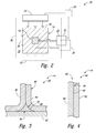
Fig. 2 is a diagram schematically representing systems for curing complex fiber-reinforced composite structures. -
Fig. 3 is a cross-sectional view of an illustrative, non-exclusive example of a complex fiber-reinforced composite structure. -
Fig. 4 is a cross-sectional view of another illustrative, non-exclusive example of a complex fiber-reinforced composite structure. -
Fig. 5 is a chart graphically representing an illustrative, non-exclusive example of timing associated with curing complex fiber-reinforced composite structures. -
Fig. 6 is a flowchart schematically representing methods for curing complex fiber-reinforced composite structures and methods for assembling composite apparatuses. - Systems and methods for curing complex fiber-reinforced composite structures, methods of assembling complex fiber-reinforced composite structures, methods of assembling apparatuses with complex fiber-reinforced composite structures, and apparatuses with complex fiber-reinforced composite structures are disclosed herein. Generally, in the figures, elements that are likely to be included in a given example are illustrated in solid lines, while elements that are optional to a given example are illustrated in broken lines. However, elements that are illustrated in solid lines are not essential to all examples of the present disclosure, and an element shown in solid lines may be omitted from a particular example without departing from the scope of the present disclosure.
- As used herein, a "complex fiber-reinforced composite structure" is a structure constructed of fiber-reinforced composite material and that includes at least two distinct regions having different physical and/or thermal characteristics from each other. One or more interfaces are defined between, or at the engagement or intersection of, the distinct regions. Examples of different physical characteristics include such characteristics as different fiber materials, different fiber orientations, different fiber sizes, different fiber densities, different resin materials, different layer thicknesses, different layer orientations, and different coefficient of thermal expansions. In a complex fiber-reinforced composite structure, the interface between two regions creates a thermal discontinuity between the two regions. Accordingly, when a complex fiber-reinforced composite structure is heated, such as during a curing process, the interface may affect the conduction of heat from one region to an adjacent region across the interface.
- Fiber-reinforced composite structures, in general, include at least an epoxy, resin, or other polymer or binding material together with fibers, such as constructed of (but not limited to) glass fibers, carbon fibers, boron fibers, para-aramid (e.g., Kevlar®) fibers, and/or other fibers. In some examples, composite structures may be constructed of multiple layers, or plies, of fiber reinforced composite material. Accordingly, a complex fiber-reinforced composite structure may include an assembly of two or more individual segments of fiber-reinforced composite structures that are combined or joined to define an interface, as discussed above, such as with the two or more individual segments having different fiber and/or binding material characteristics, as discussed above.
- Various apparatuses, including aerospace structures, are increasingly being constructed of fiber-reinforced composite materials. In
Fig. 1 , anexample apparatus 10 in the form of anaircraft 12, for example, is schematically indicated as including various complex fiber-reinforcedcomposite structures 14 throughout the aircraft. As illustrative and non-exclusive examples, one or more of a stringer, a stringer and skin assembly, a wing spar, a wing spar and skin assembly, a wing rib, a wing rib and spar assembly, a wing rib and skin assembly, a frame member, a frame member and skin assembly, and a joint or assembly between more than one fiber-reinforced composite part may define a complex fiber-reinforcedcomposite structure 14. - While the example of
Fig. 1 and discussions herein generally relate to aerospace structures,apparatuses 10 other than aircraft are within the scope of the present disclosure and may include complex fiber-reinforced composite structures. For example, other apparatuses that may include complex fiber-reinforced composite structures include (but are not limited to) spacecraft, watercraft, land vehicles, wind turbines, structural towers and masts, etc. Moreover,aircraft 12 may take any suitable form, including commercial aircraft, military aircraft, private aircraft, or any other suitable aircraft. WhileFig. 1 illustratesaircraft 12 in the form of a fixed wing commercial aircraft, other types and configurations of aircraft are within the scope ofaircraft 12 according to the present disclosure, including (but not limited to) helicopters. -
Fig. 2 provides a schematic representation of illustrative, non-exclusive examples ofsystems 20 for curing complex fiber-reinforcedcomposite structures 14.Systems 20 include at least afirst heat source 22 and asecond heat source 24 that is distinct from the first heat source. As schematically illustrated with an arrow representing heat, thefirst heat source 22 is configured to apply heat to aninternal portion 18 of a complex fiber-reinforcedcomposite structure 14 to be cured for conductive heating of the complex fiber-reinforced composite structure from the internal portion outward. As also schematically illustrated with an arrow representing heat, thesecond heat source 24 is configured to apply heat to anexternal surface 16 of the complex fiber-reinforcedcomposite structure 14 for conductive heating of the complex fiber-reinforced composite structure from the external surface inward. - The
first heat source 22 may include a heater, or heat assembly, 23 configured to contact an exposed portion of theinternal portion 18 of the complex fiber-reinforcedcomposite structure 14 being cured for conductive heating of the internal portion and thus for conductive heating of the complex fiber-reinforced composite structure from the internal portion outward. Illustrative, non-exclusive examples ofheaters 23 include (but are not limited to) heat pads, heat blankets, and resistive heaters, optionally powered by such commercial power supplies as HEATCON™ 6500, AGILENT™ U8001A, or HP™ 6012B. - Generally, the
second heat source 24 is a heat source that is configured to heat an entirety of theexternal surface 16 of the complex fiber-reinforced composite structure being cured. Illustrative, non-exclusive examples ofsecond heat sources 24 include (but are not limited to) an autoclave, an oven, and heating pads or blankets. InFig. 2 an autoclave oroven 30 having aninternal volume 32 sized to receive a complex fiber-reinforcedcomposite structure 14 to be cured is schematically illustrated. As also optionally illustrated inFig. 2 , one or more heating pads orblankets 34 may be engaged with theexternal surface 16 to heat the complex fiber-reinforced composite structure being cured from the external surface inward. - As optionally illustrated in
Fig. 2 , somesystems 20 additionally may include aheat sink 26 that is configured to actively withdraw heat from theinternal portion 18 of the complex fiber-reinforcedcomposite structure 14 to cool the complex fiber-reinforced composite structure from within the internal portion. By actively withdraw heat, it is meant that the heat sink is a mechanism specifically designed and intended to withdraw heat from the complex fiber-reinforced composite structure being cured via conduction, as opposed to merely being an ambient environment at a lower temperature. InFig. 2 , theoptional heat sink 26 is illustrated in an overlapping relationship with thefirst heat source 22, schematically representing that the first heat source or associated heater share structure for both applying heat to and withdrawing heat from the internal portion of the complex fiber-reinforced composite structure being cured. In fact, in some examples, the heat sink and the first heat source optionally may be the same mechanism or tool, but operative to selectively heat and to selectively cool, depending on user preference or automation of asystem 20. - As also optionally illustrated in
Fig. 2 , somesystems 20 additionally may include acooling device 27 that is configured to withdraw heat from theexternal surface 16 of the complex fiber-reinforcedcomposite structure 14, for example, to cool the complex fiber-reinforced composite structure from the external surface and/or to maintain a desired temperature of the external surface, or portion thereof, while thefirst heat source 22 is actively heating theinternal portion 18. As an illustrative non-exclusive example, the cooling device may utilize convection and may include one or more of a fan or an air conditioner. InFig. 2 , theoptional cooling device 27 is illustrated in an overlapping relationship with the optional autoclave oroven 30, schematically representing that the cooling device optionally may be integral to, a component of, and/or utilized with an autoclave or oven, such as by providing convective processes within theinternal volume 32 thereof. - While
Fig. 2 very schematically illustrates a complex fiber-reinforcedcomposite structure 14 having aninternal portion 18,Figs. 3 and 4 provide somewhat less schematic illustrative, non-exclusive examples of complex fiber-reinforcedcomposite structures 14. For example, inFig. 3 a complex fiber-reinforcedcomposite structure 38 represents in cross-section a complex fiber-reinforcedcomposite structure 14 in the form of aspar 40 operatively coupled to askin 42 and having a radius filler, or noodle, 48 defining an internal portion between the spar and the skin, with the remainder of the complex-fiber reinforced composite material optionally described as an external portion of the complex fiber-reinforced composite material. For example, the spar may represent a wing spar in an aerospace application. More specifically, the spar is illustrated as being defined by two sheets, or sheet portions, 44, 46 that are operatively coupled to each other and to theskin 42, collectively defining an external portion, and with theradius filler 48 defining the internal portion and filling the space between thesheet portions skin 42. Radius fillers are structures that are used in applications such as spars, stringers, frame members, and the like coupled to skins of aircraft, for example, to fill voids that are a result of two composite structures being joined together, such as at a bend in a sheet of composite material, as in the example ofFig. 3 , or at the termination, or edge, of a sheet of composite material on another sheet of composite material, such as a skin. - With continued reference to the example of
Fig. 3 , theinternal portion 18 of a complex fiber-reinforcecomposite structure 14, such as in the form of anoodle 48, may include heatconductive fibers 50, whose ends are exposed. Accordingly, in asystem 20, thefirst heat source 22 may be configured to apply heat to the exposed ends of the heat conductive fibers for conduction along the lengths of the heat conductive fibers. Moreover, in asystem 20 including anoptional heat sink 26, the heat sink may be configured to withdraw heat from the exposed ends of the heat conductive fibers to cool the complex fiber-reinforced composite structure from within the internal portion. - As illustrative, non-exclusive examples, the heat
conductive fibers 50 of aninternal portion 18 of a complex fiber-reinforcedcomposite structure 14 may be composed of one or more of carbon, pitch-based carbon, carbon nano-tubes, metal, copper, and metal alloy. Additionally or alternatively, the heatconductive fibers 50 may be constructed of a material that has a higher thermal conductivity than the surrounding binding material. Additionally or alternatively, the heatconductive fibers 50 may have a thermal conductivity greater than 400 W/(m*K), greater than 700 W/(m*K), or greater than 1000 W/(m*K). Additionally or alternatively, theinternal portion 18, as a whole, may have such examples of thermal conductivity. - Some complex fiber-reinforced
composite structures 14 may be described as having an elongate body with a longitudinal axis, such as corresponding to a length of a spar, a stringer, or a frame member, and with the heatconductive fibers 50 generally being aligned with the longitudinal axis. Accordingly, when thefirst heat source 22 applies heat to the exposed ends of the heatconductive fibers 50, heat is conducted along the lengths of the heat conductive fibers to heat theinternal portion 18 and thus to heat the complex fiber-reinforcedcomposite structure 14 being cured from within. In some complex fiber-reinforcedcomposite structures 14, fibers outside of theinternal portion 18 may not be generally or substantially aligned with the longitudinal axis of the complex fiber-reinforced composite structure, for example, thereby defining one example of a difference in physical characteristics and an interface between two regions of the complex fiber-reinforced composite structure. Additionally or alternatively, the heatconductive fibers 50 of aninternal portion 18 may be composed of a material that is different than the fibers within a remainder of the complex fiber-reinforcedcomposite structure 14, thereby defining another example of a difference in physical characteristics and an interface between two regions of the complex fiber-reinforced composite structure. - Turning to the illustrative, non-exclusive example of the complex fiber-reinforced
composite structure 60 illustrated inFig. 4 , a complex fiber-reinforcedcomposite structure 14 additionally or alternatively may include a plurality oflayers 68 of fiber-reinforced composite material, with theinternal portion 18 being defined by at least oneinternal layer 66 of the plurality oflayers 68, and with the external portion being defined by one or moreexternal layers internal portion 18. - Returning to
Fig. 2 ,systems 20 optionally also may include acontroller 28 that is configured, or programmed, to control timing of the application of heat to the complex fiber-reinforcedcomposite structure 14 from thefirst heat source 22 and timing of the application of heat to the complex fiber-reinforced composite structure from thesecond heat source 24. Additionally, thecontroller 28 may be configured, or programmed, to actively monitor temperatures of one or more regions of the complex fiber-reinforcedcomposite structure 14 being cured, and based at least in part on such monitoring, actively control the timing of the application of heat to the complex fiber-reinforced composite structure from the first heat source and the timing of the application of heat to the complex fiber-reinforced composite structure from the second heat source.Controller 28 may include any suitable structure or structures that may be adapted, configured, designed, constructed, and/or programmed to automatically control, or selectively control via a user, the operation of asystem 20, including thefirst heat source 22 and/or thesecond heat source 24. As illustrative, non-exclusive examples, acontroller 28 may include and/or be one or more of an electronic controller, a dedicated controller, a special-purpose controller, a personal computer, a display device, a logic device, a memory device, instrumentation, sensors, including temperature sensors, etc. In addition,controller 28 may be programmed to perform one or more algorithms to automatically control the operation of asystem 20. This may include algorithms that may be based upon and/or that may causecontroller 28 to directsystem 20 to perform amethod 102 according to the present disclosure. - As an illustrative, non-exclusive example and with reference to
Fig. 5 with the temperature of theinternal portion 18 represented by the dash-dot-dot line 120 and with the temperature of theexternal surface 16 represented by the dashedline 122, thecontroller 28 may be programmed to initiate heating of the complex fiber-reinforcedcomposite structure 14 with thefirst heat source 22 prior in time to initiation of heating of the complex fiber-reinforcedcomposite structure 14 with thesecond heat source 24.Fig. 5 additionally or alternatively may schematically represent the application and/or withdrawal of heat to and/or from the internal portion and the external surface in relation to time and not merely the temperature of the internal portion and the external surface over time. For example, where the initial portion ofline 122 is flat, optionally representing no application of heat to the external surface, the temperature of the external surface may in fact be increasing over this period due to the conduction of heat from the internal portion. - Additionally or alternatively, the
controller 28 may be programmed to cease heating of the complex fiber-reinforced composite structure with the first heat source prior in time to cessation of heating of the complex fiber-reinforced composite structure with the second heat source. Additionally or alternatively, the controller may be programmed to cease heating of the complex fiber-reinforced composite structure with the first heat source prior to initiation of heating the complex fiber-reinforced composite structure with the second heat source. Additionally or alternatively, the controller may be programmed to cease heating of the complex fiber-reinforced composite structure with the first heat source at the same or approximately the same time as initiation of heating the complex fiber-reinforced composite structure with the second heat source. - Additionally or alternatively, in example of
systems 20 that include anoptional heat sink 26, thecontroller 28 may be programmed to initiate withdrawal of heat from the complex fiber-reinforcedcomposite structure 14 withheat sink 26 prior to initiation of heating the complex fiber-reinforced composite structure with thesecond heat source 24. Additionally or alternatively, the controller may be programmed to initiate withdrawal of heat from the complex fiber-reinforced composite structure with the heat sink at the same or approximately the same time as initiation of heating the complex fiber-reinforced composite structure with the second heat source. Additionally or alternatively, the controller may be programmed to initiate withdrawal of heat from the complex fiber-reinforced composite structure with the heat sink at a moment in time after initiation of heating the complex fiber-reinforced composite structure with thesecond heat source 24. Other examples also are within the scope of the present disclosure, andFig. 5 illustrates just one example that may be implemented with systems and methods according to the present disclosure. - Additionally or alternatively, in examples of
systems 20 that include anoptional cooling device 27, thecontroller 28 may be programmed to withdraw heat from the complex fiber-reinforcedcomposite structure 14 via theexternal surface 16 withcooling device 27 during a period in which thefirst heat source 22 is heating theinternal portion 18. -
Fig. 6 schematically provides a flowchart that represents illustrative, non-exclusive examples ofmethods 100 according to the present disclosure. InFig. 6 , some steps are illustrated in dashed boxes indicating that such steps may be optional or may correspond to an optional version of a method according to the present disclosure. That said, not all methods according to the present disclosure are required to include the steps illustrated in solid boxes. The methods and steps illustrated inFig. 6 are not limiting and other methods and steps are within the scope of the present disclosure, including methods having greater than or fewer than the number of steps illustrated, as understood from the discussions herein. In the following discussion, reference is made to the component parts ofsystems 20 and complex fiber-reinforced composite structures, including utilization of corresponding reference numerals thereof; however,methods 100 are not limited to being implemented with and/or bysystems 20 according to the present disclosure. - As illustrated in solid boxes in
Fig. 6 , amethod 102 of curing a complex fiber-reinforcedcomposite structure 14 includes applying 104 heat from afirst heat source 22 to aninternal portion 18 of a complex fiber-reinforcedcomposite structure 14 for conductive heating of the complex fiber-reinforced composite structure from the internal portion, and applying 106 heat from asecond heat source 24 distinct from thefirst heat source 22 to anexternal surface 16 of the complex fiber-reinforcedcomposite structure 14 for conductive heating of the complex fiber-reinforced composite structure from the external surface. While the applying 106 is schematically illustrated below the applying 104,methods 102 are not limited to application of heat from the first heat source necessarily occurring or being initiated prior in time to the application of heat from the second heat source. - In some
methods 102, the applying 104 may include contacting an exposed portion of theinternal portion 18 of the complex fiber-reinforcedcomposite structure 14 with thefirst heat source 22 for conductive heating of theinternal portion 18, and thus for heating of the complex fiber-reinforced composite structure from within. - In some
methods 102, such as in connection with the internal portion of a complex fiber-reinforced composite structure including heatconductive fibers 50, the applying 104 may include applying heat to exposed ends of the heatconductive fibers 50 for conduction along lengths of the heat conductive fibers within the internal portion, and thus for conductive heating of the complex fiber-reinforced composite structure from the internal portion. - As schematically and optionally illustrated in
Fig. 6 , somemethods 102 also may include following the applying 104, actively withdrawing 108 with aheat sink 26 heat from theinternal portion 18 of the complex fiber-reinforcedcomposite structure 14 being cured to cool the complex fiber-reinforced composite structure from within the internal portion. In somesuch methods 102, the withdrawing 108 may include withdrawing heat from the ends of the heatconductive fibers 50 to cool the complex fiber-reinforced composite structure from the internal portion. - In some
methods 102, the applying 104 may be initiated prior in time to the applying 106. Additionally or alternatively, the applying 104 may be ceased prior in time to ceasing the applying 106. Additionally or alternatively, the applying 104 may be ceased prior to initiation of the applying 106. Additionally or alternatively, the applying 104 may be ceased at the same or approximately the same time as initiation of the applying 106. Additionally or alternatively, inmethods 102 that include optional withdrawing 108, the withdrawing 108 may be initiated prior to initiation of the applying 106. Additionally or alternatively, the withdrawing 108 may be initiated at the same or approximately the same time as initiation of the applying 106. Additionally or alternatively, somemethods 102 further include actively monitoring temperatures of one or more regions of the complex fiber-reinforced composite structure, and based at least in part on the actively monitoring, actively controlling timing of the applying 104, the applying 106, and optionally the withdrawing 108. - As schematically and optionally illustrated in
Fig. 6 , somemethods 102 also may include withdrawing 109 with acooling device 27 heat from the complex fiber-reinforcedcomposite structure 14 via theexternal surface 16 concurrently with applying 104. In somesuch methods 102, the withdrawing 109 may be performed to maintain a desired temperature of the external surface during the applying 104. In somesuch methods 102, the withdrawing 109 may include withdrawing heat via convection. -
Methods 100 also may include assembling 110 a complex fiber-reinforcedcomposite structure 14 prior to curing 102, as schematically indicated inFig. 6 . That is, assembling 110 may include constructing a complex fiber-reinforcedcomposite structure 14 that includes at least two regions with an interface between regions, and optionally including aninternal portion 18, as discussed herein. -
Methods 100 also may include following curing 102, assembling 112 anapparatus 10 with one or more complex fiber-reinforcedcomposite structures 14. - According to a first aspect, the application also discloses:
- A system for curing complex fiber-reinforced composite structures, the system comprising:
- a first heat source configured to apply heat to an internal portion of a complex fiber-reinforced composite structure for conductive heating of the complex fiber-reinforced composite structure from the internal portion; and
- a second heat source distinct from the first heat source configured to apply heat to an external surface of the complex fiber-reinforced composite structure for conductive heating of the complex fiber-reinforced composite structure from the external surface.
- Optionally, the system further comprises:
- a heat sink configured to actively withdraw heat from the internal portion of the complex fiber-reinforced composite structure to cool the complex fiber-reinforced composite structure from within the internal portion.
- Optionally, the second heat source includes one of an autoclave and an oven with an internal volume sized to receive the complex fiber-reinforced composite structure.
- Optionally, the second heat source includes one or more heating pads or blankets configured to engage the external surface.
- Optionally, the first heat source includes a heater configured to contact an exposed portion of the internal portion of the complex fiber-reinforced composite structure for conductive heating of the internal portion.
- Optionally, the heater and the heat sink share structure for applying heat to and withdrawing heat from the internal portion of the complex fiber-reinforced composite structure.
- Optionally, the system further comprising the complex fiber-reinforced composite structure.
- Optionally, the complex fiber-reinforced composite structure includes at least two regions having different physical characteristics from each other, and wherein the internal portion of the complex fiber-reinforced composite structure defines at least a portion of an interface between the at least two regions.
- Optionally, the different physical properties include one or more of different fiber material, different fiber orientation, different fiber size, different fiber density, different resin material, different layer thickness, different layer orientation, and different coefficient of thermal expansion.
- Optionally, the complex fiber-reinforced composite structure includes at least two regions having different thermal characteristics from each other, and wherein the internal portion of the complex fiber-reinforced composite structure includes one of the at least two regions.
- Optionally, the complex fiber-reinforced composite structure includes at least one interface between two regions, wherein the interface creates a thermal discontinuity between the two regions, and wherein the internal portion of the complex fiber-reinforced composite structure includes one of the two regions.
- Optionally, the internal portion of the complex fiber-reinforced composite structure includes a radius filler.
- Optionally, the complex fiber-reinforced composite structure includes at least two sheets of fiber-reinforced composite material that define an/the interface.
- Optionally, the complex fiber-reinforced composite structure includes at least two sheets of fiber-reinforced composite material and a radius filler of fiber-reinforced composite material positioned between the at least two sheets.
- Optionally, the complex fiber-reinforced composite structure includes a plurality of layers of fiber-reinforced composite material, and wherein the internal portion of the complex fiber-reinforced composite structure includes at least one layer of the plurality of layers.
- Optionally, the complex fiber-reinforced composite structure includes one or more of a stringer, a stringer and skin assembly, a wing spar, a wing spar and skin assembly, a wing rib, a wing rib and spar assembly, a wing rib and skin assembly, a frame member, a frame member and skin assembly, and a joint or assembly between more than one fiber-reinforced composite part.
- Optionally, the internal portion includes heat conductive fibers, and wherein the first heat source is configured to apply heat to ends of the heat conductive fibers for conduction along lengths of the heat conductive fibers within the internal portion for conductive heating of the complex fiber-reinforced composite structure from the internal portion.
- Optionally, the heat sink is configured to withdraw heat from the ends of the heat conductive fibers to cool the complex fiber-reinforced composite structure from the internal portion.
- Optionally, the heat conductive fibers are composed of one or more of carbon, pitch-carbon, carbon nanotubes, metal, copper, metal alloy, and material having a thermal conductivity greater than 400 W/(m*K), greater than 700 W/(m*K), or greater than 1000 W/(m*K).
- Optionally, the complex fiber-reinforced composite structure has a longitudinal axis, and wherein the heat conductive fibers are generally aligned with the longitudinal axis.
- Optionally, fibers outside of the internal portion of the complex fiber-reinforced composite structure are generally aligned with, are not generally aligned with, or are not substantially generally aligned with the longitudinal axis.
- Optionally, the heat conductive fibers are composed of a material different than fibers within a remainder of the complex fiber-reinforced composite structure.
- Optionally, the system further comprises:
- a cooling device configured to withdraw heat from the external surface of the complex fiber-reinforced composite structure to maintain a desired temperature of the external surface.
- Optionally, the system further comprises:
- a controller programmed to control timing of the application of heat to the complex fiber-reinforced composite structure from the first heat source and timing of the application of heat to the complex fiber-reinforced composite structure from the second heat source.
- Optionally, the controller is programmed to initiate heating of the complex fiber-reinforced composite structure with the first heat source prior in time to initiation of heating of the complex fiber-reinforced composite structure with the second heat source.
- Optionally, the controller is programmed to cease heating of the complex fiber-reinforced composite structure with the first heat source prior in time to cessation of heating of the complex fiber-reinforced composite structure with the second heat source.
- Optionally, the controller is programmed to cease heating of the complex fiber-reinforced composite structure with the first heat source prior to initiation of heating the complex fiber-reinforced composite structure with the second heat source.
- Optionally, the controller is programmed to cease heating of the complex fiber-reinforced composite structure with the first heat source at the same or approximately the same time as initiation of heating the complex fiber-reinforced composite structure with the second heat source.
- Optionally, the controller is programmed to initiate withdrawal of heat from the complex fiber-reinforced composite structure with the heat sink prior to initiation of heating the complex fiber-reinforced composite structure with the second heat source.
- Optionally, the controller is programmed to initiate withdrawal of heat from the complex fiber-reinforced composite structure with the heat sink at the same or approximately the same time as initiation of heating the complex fiber-reinforced composite structure with the second heat source.
- Optionally, the controller is configured to direct the cooling device to withdraw heat from the external surface while the first heat source is heating the internal portion.
- Optionally, the controller is programmed to actively monitor temperatures of one or more regions of the complex fiber-reinforced composite structure, and based at least in part on such monitoring, actively control the timing of the application of heat to the complex fiber-reinforced composite structure from the first heat source and the timing of the application of heat to the complex fiber-reinforced composite structure from the second heat source.
- Optionally, the system is configured to perform at least in part the method of any of third aspect and/or any optional feature thereof.
- According to a second aspect, the application also discloses the use of the system of any of the first aspect and/or any optional feature thereof.
- According to a third aspect, the application further discloses a method for curing complex fiber-reinforced composite structures, the method comprising:
- applying heat from a first heat source to an internal portion of a complex fiber-reinforced composite structure for conductive heating of the complex fiber-reinforced composite structure from the internal portion; and
- applying heat from a second heat source distinct from the first heat source to an external surface of the complex fiber-reinforced composite structure for conductive heating of the complex fiber-reinforced composite structure from the external surface.
- Optionally, the method further comprises:
- following the applying heat from the first heat source, actively withdrawing heat with a heat sink from the internal portion of the complex fiber-reinforced composite structure to cool the complex fiber-reinforced composite structure from within the internal portion.
- Optionally, the second heat source includes one of an autoclave and an oven with an internal volume sized to receive the complex fiber-reinforced composite structure.
- Optionally, the second heat source includes one or more heating pads or blankets configured to engage the external surface.
- Optionally, applying heat from the first heat source includes contacting an exposed portion of the internal portion of the complex fiber-reinforced composite structure with the first heat source for conductive heating of the internal portion.
- Optionally, the first heat source and the heat sink share structure for applying heat to and withdrawing heat from the internal portion of the complex fiber-reinforced composite structure.
- Optionally, the complex fiber-reinforced composite structure includes at least two regions having different physical characteristics from each other, and wherein the internal portion of the complex fiber-reinforced composite structure defines at least a portion of an interface between the at least two regions.
- Optionally, the different physical properties include one or more of different fiber material, different fiber orientation, different fiber size, different fiber density, different resin material, different layer thickness, different layer orientation, and different coefficient of thermal expansion.
- Optionally, the complex fiber-reinforced composite structure includes at least two regions having different thermal characteristics from each other, and wherein the internal portion of the complex fiber-reinforced composite structure includes one of the at least two regions.
- Optionally, the complex fiber-reinforced composite structure includes at least one interface between two regions, optionally wherein the interface creates a thermal discontinuity between the two regions, and optionally wherein the internal portion of the complex fiber-reinforced composite structure includes one of the two regions.
- Optionally, the internal portion of the complex fiber-reinforced composite structure includes a radius filler.
- Optionally, the complex fiber-reinforced composite structure includes at least two sheets of fiber-reinforced composite material that define an/the interface.
- Optionally, the complex fiber-reinforced composite structure includes at least two sheets of fiber-reinforced composite material and a radius filler of fiber-reinforced composite material positioned between the at least two sheets.
- Optionally, the complex fiber-reinforced composite structure includes a plurality of layers of fiber-reinforced composite material, and wherein the internal portion of the complex fiber-reinforced composite structure includes at least one layer of the plurality of layers.
- Optionally, the complex fiber-reinforced composite structure includes one or more of a stringer, a stringer and skin assembly, a wing spar, a wing spar and skin assembly, a wing rib, a wing rib and spar assembly, a wing rib and skin assembly, a frame member, a frame member and skin assembly, and a joint or assembly between more than one fiber-reinforced composite part.
- Optionally, the internal portion includes heat conductive fibers, and wherein the applying heat from the first heat source includes applying heat to ends of the heat conductive fibers for conduction along lengths of the heat conductive fibers within the internal portion for conductive heating of the complex fiber-reinforced composite structure from the internal portion, optionally wherein the heat conductive fibers are constructed of a material different than fibers within a remainder of the complex fiber-reinforced composite structure.
- Optionally, withdrawing heat with the heat sink includes withdrawing heat from the ends of the heat conductive fibers to cool the complex fiber-reinforced composite structure from the internal portion.
- Optionally, the heat conductive fibers are composed of one or more of carbon, pitch-carbon, carbon nano-tubes, metal, copper, metal alloy, and material having a thermal conductivity greater than 400 W/(m*K), greater than 700 W/(m*K), or greater than 1000 W/(m*K).
- Optionally, the complex fiber-reinforced composite structure has a longitudinal axis, and wherein the heat conductive fibers are generally aligned with the longitudinal axis.
- Optionally, fibers outside of the internal portion of the complex fiber-reinforced composite structure are generally aligned with, are not generally aligned with, or are not substantially generally aligned with the longitudinal axis.
- Optionally, applying heat from the first heat source is initiated prior in time to the applying heat from the second heat source.
- Optionally, applying heat from the first heat source is ceased prior in time to ceasing the applying heat from the second heat source.
- Optionally, applying heat from the first heat source is ceased prior to initiation of the applying heat with the second heat source.
- Optionally, applying heat with the first heat source is ceased at the same or approximately the same time as initiation of the applying the heat with the second heat source.
- Optionally, withdrawing heat with the heat sink is initiated prior to initiation of the applying heat with the second heat source.
- Optionally, withdrawing heat with the heat sink is initiated at the same or approximately the same time as initiation of the applying heat with the second heat source.
- Optionally, the method further comprises:
- withdrawing heat from the complex fiber-reinforced composite structure via the external surface, optionally concurrently with the applying heat from the first heat source and prior to the applying heat from the second heat source.
- Optionally, the method further comprises: actively monitoring temperatures of one or more regions of the complex fiber-reinforced composite structure; and
based at least in part on the actively monitoring, actively controlling timing of the applying heat from the first heat source and the applying heat from the second heat source. - According to a fourth aspect, the application discloses a method, comprising:
- performing the method of the third aspect and/or any optional feature thereof; and
- prior to the performing, assembling the complex fiber-reinforced composite structure.
- According to a fifth aspect, the application discloses a method of assembling an apparatus, comprising:
- performing the method of the fourth aspect; and
- following the performing, assembling an apparatus including one or more fiber-reinforced composite materials, optionally wherein the apparatus includes or is a vehicle, an aerospace vehicle, or a marine vehicle.
- Optionally, method of any of the third aspect and/or any optional feature thereof is performed at least in part by the system of any of the first aspect and/or any optional feature thereof.
- According to a sixth aspect, the application discloses, a complex fiber-reinforced composite structure, comprising: an elongate body having an internal portion constructed of fiber-reinforced composite material and an external portion constructed of fiber-reinforced composite material, wherein the internal portion includes a plurality of heat conductive fibers that extend longitudinally along the elongate body with exposed ends that are configured to be operatively coupled to a heat source for conductively heating the heat conductive fibers for at least partially curing the complex fiber-reinforced composite structure from within the elongate body.
- Optionally, the elongate body includes one or more of a stringer, a stringer and skin assembly, a wing spar, a wing spar and skin assembly, a wing rib, a wing rib and spar assembly, a wing rib and skin assembly, a frame member, a frame member and skin assembly, and a joint or assembly between more than one fiber-reinforced composite part.
- Optionally, the internal portion includes a radius filler.
- Optionally, the internal portion and the external portion have different physical characteristics from each other.
- Optionally, the different physical properties include one or more of different fiber material, different fiber orientation, different fiber size, different fiber density, different resin material, different layer thickness, different layer orientation, and different coefficient of thermal expansion.
- Optionally, the internal portion and the external portion have different thermal characteristics from each other.
- Optionally, an interface between the internal portion and the external portion creates a thermal discontinuity between the two portions.
- Optionally, the elongate body includes at least two sheets of fiber-reinforced composite material that define an/the interface.
- Optionally, the elongate body includes at least two sheets of fiber-reinforced composite material and a radius filler of fiber-reinforced composite material positioned between the at least two sheets.
- Optionally, the elongate body includes a plurality of layers of fiber-reinforced composite material, and wherein the internal portion of the complex fiber-reinforced composite structure includes at least one layer of the plurality of layers.
- Optionally, the heat conductive fibers are composed of one or more of carbon, pitch-carbon, carbon nanotubes, metal, copper, metal alloy, and material having a thermal conductivity greater than 400 W/(m*K), greater than 700 W/(m*K), or greater than 1000 W/(m*K).
- Optionally, the elongate body has a longitudinal axis, and wherein the heat conductive fibers are generally aligned with the longitudinal axis.
- Optionally, fibers within the external portion are generally aligned with, are not generally aligned with, or are not substantially generally aligned with the longitudinal axis.
- Optionally, the heat conductive fibers are composed of a material different than fibers within the external portion.
- According to a seventh aspect, the application discloses the use of the complex fiber-reinforced composite structure of any of the sixth aspect and/or any optional feature thereof.
- As used herein, the terms "adapted" and "configured" mean that the element, component, or other subject matter is designed and/or intended to perform a given function. Thus, the use of the terms "adapted" and "configured" should not be construed to mean that a given element, component, or other subject matter is simply "capable of" performing a given function but that the element, component, and/or other subject matter is specifically selected, created, implemented, utilized, programmed, and/or designed for the purpose of performing the function. It is also within the scope of the present disclosure that elements, components, and/or other recited subject matter that is recited as being adapted to perform a particular function may additionally or alternatively be described as being configured to perform that function, and vice versa. Similarly, subject matter that is recited as being configured to perform a particular function may additionally or alternatively be described as being operative to perform that function.
- Further, the disclosure comprises embodiments according to the following clauses:
-
Clause 1. Amethod 102 for curing complex fiber-reinforcedcomposite structures 14, themethod 102 comprising:- applying 104 heat from a
first heat source 22 to aninternal portion 18 of a complex fiber-reinforcedcomposite structure 14 for conductive heating of the complex fiber-reinforcedcomposite structure 14 from theinternal portion 18, wherein the applying 104 heat from thefirst heat source 22 includes contacting an exposed portion of theinternal portion 18 of the complex fiber-reinforcedcomposite structure 14 with thefirst heat source 22 for conductive heating of theinternal portion 18; and - applying 106 heat from a
second heat source 24 distinct from thefirst heat source 22 to anexternal surface 16 of the complex fiber-reinforcedcomposite structure 14 for conductive heating of the complex fiber-reinforcedcomposite structure 14 from theexternal surface 16.
- applying 104 heat from a
- Clause 2. The
method 102 ofclause 1, further comprising:- following the applying 104 heat from the
first heat source 22, actively withdrawing 108 heat with aheat sink 26 from theinternal portion 18 of the complex fiber-reinforcedcomposite structure 14 to cool the complex fiber-reinforcedcomposite structure 14 from within theinternal portion 18.
- following the applying 104 heat from the
- Clause 3. The
method 102 of clause 2, wherein thefirst heat source 22 and theheat sink 26 share structure for applying 104 heat to and withdrawing 108 heat from theinternal portion 18 of the complex fiber-reinforcedcomposite structure 14. - Clause 4. The
method 102 of any of clauses 1-3, wherein thesecond heat source 24 includes one of anautoclave 30 and anoven 30 with aninternal volume 32 sized to receive the complex fiber-reinforcedcomposite structure 14. - Clause 5. The
method 102 of any of clauses 1-3, wherein thesecond heat source 24 includes one ormore heating pads 34 orblankets 34 configured to engage theexternal surface 16. - Clause 6. The
method 102 of any of clauses 1-5, wherein the complex fiber-reinforcedcomposite structure 14 includes at least two regions having different physical characteristics from each other, and wherein theinternal portion 18 of the complex fiber-reinforcedcomposite structure 14 defines at least a portion of an interface between the at least two regions, and wherein the different physical properties includes one or more of different fiber material, different fiber orientation, different fiber size, different fiber density, different resin material, different layer thickness, different layer orientation, and different coefficient of thermal expansion. - Clause 7. The
method 102 of any of clauses 1-5, wherein the complex fiber-reinforcedcomposite structure 14 includes at least two regions having different thermal characteristics from each other, and wherein theinternal portion 18 of the complex fiber-reinforcedcomposite structure 14 includes one of the at least two regions. - Clause 8. The
method 102 of any of clauses 1-5, wherein the complex fiber-reinforcedcomposite structure 14 includes at least one interface between two regions, wherein the interface creates a thermal discontinuity between the two regions, and wherein theinternal portion 18 of the complex fiber-reinforcedcomposite structure 14 includes one of the two regions. - Clause 9. The
method 102 of any of clauses 1-8, wherein theinternal portion 18 of the complex fiber-reinforcedcomposite structure 14 includes aradius filler 48. -
Clause 10. Themethod 102 of any of clauses 1-5, wherein the complex fiber-reinforcedcomposite structure 14 includes at least two sheets of fiber-reinforced composite material and aradius filler 48 of fiber-reinforced composite material positioned between the at least two sheets. - Clause 11. The
method 102 of any of clauses 1-5, wherein the complex fiber-reinforcedcomposite structure 14 includes a plurality oflayers 68 of fiber-reinforced composite material, and wherein theinternal portion 18 of the complex fiber-reinforcedcomposite structure 14 includes at least one layer of the plurality oflayers 68. -
Clause 12. Themethod 102 of clauses 1-5, wherein the complex fiber-reinforcedcomposite structure 14 includes one or more of a stringer, a stringer and skin assembly, a wing spar, a wing spar and skin assembly, a wing rib, a wing rib and spar assembly, a wing rib and skin assembly, a frame member, a frame member and skin assembly, and an assembly between more than one fiber-reinforced composite part. - Clause 13. The
method 102 of any of clauses 1-5, wherein theinternal portion 18 includes heatconductive fibers 50, and wherein the applying 104 heat from thefirst heat source 22 includes applying heat to ends of the heatconductive fibers 50 for conduction along lengths of the heatconductive fibers 50 within theinternal portion 18 for conductive heating of the complex fiber-reinforcedcomposite structure 14 from theinternal portion 18. -
Clause 14. Themethod 102 of clause 13, wherein the heatconductive fibers 50 are constructed of a material different than fibers within a remainder of the complex fiber-reinforcedcomposite structure 14. - Clause 15. The
method 102 of clause 13, wherein the complex fiber-reinforcedcomposite structure 14 has a longitudinal axis, and wherein the heatconductive fibers 50 are generally aligned with the longitudinal axis. -
Clause 16. Themethod 102 of any of clauses 1-15, wherein the applying 104 heat from thefirst heat source 22 is initiated prior in time to the applying 106 heat from thesecond heat source 24. - Clause 17. The
method 102 ofclause 16, wherein the applying 104 heat from thefirst heat source 22 is ceased prior in time to ceasing the applying 106 heat from thesecond heat source 24. -
Clause 18. Themethod 102 ofclause 16, wherein the applying 104 heat from thefirst heat source 22 is ceased prior to initiation of the applying 106 heat with thesecond heat source 24. - Clause 19. The
method 102 of any of clauses 1-18, further comprising:- actively monitoring
temperatures composite structure 14; and - based at least in part on the actively monitoring, actively controlling timing of the applying 104 heat from the
first heat source 22 and the applying 106 heat from asecond heat source 24.
- actively monitoring
-
Clause 20. Themethod 102 of any ofclauses 1 and 3-19, further comprising:- withdrawing 108 heat from the complex fiber-reinforced
composite structure 14 via theexternal surface 16 concurrently with the applying 104 heat from thefirst heat source 22 and prior to the applying 106 heat from thesecond heat source 24.
- withdrawing 108 heat from the complex fiber-reinforced
- Clause 21. A
method 102 for curing complex fiber-reinforcedcomposite structures 14, themethod 102 comprising:- applying 104 heat from a
first heat source 22 to aninternal portion 18 of a complex fiber-reinforcedcomposite structure 14 having a longitudinal axis for conductive heating of the complex fiber-reinforcedcomposite structure 14 from theinternal portion 18, wherein theinternal portion 18 includes heatconductive fibers 50 generally aligned with the longitudinal axis, wherein the heatconductive fibers 50 are constructed of a material different than fibers within a remainder of the complex fiber-reinforcedcomposite structure 14, and wherein the applying 104 heat from thefirst heat source 22 includes applying heat to ends of the heatconductive fibers 50 for conduction along lengths of the heatconductive fibers 50 within theinternal portion 18 for conductive heating of the complex fiber-reinforcedcomposite structure 14 from theinternal portion 18; and - applying 106 heat from a
second heat source 24 distinct from thefirst heat source 22 to anexternal surface 16 of the complex fiber-reinforcedcomposite structure 14 for conductive heating of the complex fiber-reinforcedcomposite structure 14 from theexternal surface 16, wherein thesecond heat source 24 includes at least one of anautoclave 30, anoven 30, aheating pad 34, and aheating blanket 34.
- applying 104 heat from a
-
Clause 22. Asystem 20 for curing complex fiber-reinforcedcomposite structures 14, thesystem 20 comprising:- a
first heat source 22 configured to apply 104 heat to aninternal portion 18 of a complex fiber-reinforcedcomposite structure 14 for conductive heating of the complex fiber-reinforcedcomposite structure 14 from theinternal portion 18, wherein thefirst heat source 22 includes a heater configured to contact an exposed portion of theinternal portion 18 of the complex fiber-reinforcedcomposite structure 14 for conductive heating of theinternal portion 18; and - a
second heat source 24 distinct from thefirst heat source 22 configured to apply 106 heat to anexternal surface 16 of the complex fiber-reinforcedcomposite structure 14 for conductive heating of the complex fiber-reinforcedcomposite structure 14 from theexternal surface 16.
- a
-
Clause 23. A complex fiber-reinforcedcomposite structure 14, comprising: an elongate body having aninternal portion 18 constructed of fiber-reinforced composite material and anexternal portion 16 constructed of fiber-reinforced composite material, wherein theinternal portion 18 includes a plurality of heatconductive fibers 50 that extend longitudinally along the elongate body with exposed ends that are configured to be operatively coupled to aheat source 22 for conductively heating the heatconductive fibers 50 for at least partially curing the complex fiber-reinforcedcomposite structure 14 from within the elongate body. - The various disclosed elements of apparatuses and steps of methods disclosed herein are not required to all apparatuses and methods according to the present disclosure, and the present disclosure includes all novel and non-obvious combinations and subcombinations of the various elements and steps disclosed herein. Moreover, one or more of the various elements and steps disclosed herein may define independent inventive subject matter that is separate and apart from the whole of a disclosed apparatus or method. Accordingly, such inventive subject matter is not required to be associated with the specific apparatuses and methods that are expressly disclosed herein, and such inventive subject matter may find utility in apparatuses and/or methods that are not expressly disclosed herein.
Claims (15)
- A method (102) for curing complex fiber-reinforced composite structures (14), the method (102) comprising:applying (104) heat from a first heat source (22) to an internal portion (18) of a complex fiber-reinforced composite structure (14) for conductive heating of the complex fiber-reinforced composite structure (14) from the internal portion (18), wherein the applying (104) heat from the first heat source (22) includes contacting an exposed portion of the internal portion (18) of the complex fiber-reinforced composite structure (14) with the first heat source (22) for conductive heating of the internal portion (18); andapplying (106) heat from a second heat source (24) distinct from the first heat source (22) to an external surface (16) of the complex fiber-reinforced composite structure (14) for conductive heating of the complex fiber-reinforced composite structure (14) from the external surface (16).
- The method (102) of claim 1, further comprising:following the applying (104) heat from the first heat source (22), actively withdrawing (108) heat with a heat sink (26) from the internal portion (18) of the complex fiber-reinforced composite structure (14) to cool the complex fiber-reinforced composite structure (14) from within the internal portion (18).
- The method (102) of claim 2, wherein the first heat source (22) and the heat sink (26) share structure for applying (104) heat to and withdrawing (108) heat from the internal portion (18) of the complex fiber-reinforced composite structure (14).
- The method (102) of any of claims 1-3, wherein the second heat source (24) includes one of an autoclave (30) and an oven (30) with an internal volume (32) sized to receive the complex fiber-reinforced composite structure (14).
- The method (102) of any of claims 1-3, wherein the second heat source (24) includes one or more heating pads (34) or blankets (34) configured to engage the external surface (16).
- The method (102) of any of claims 1-5, wherein the complex fiber-reinforced composite structure (14) includes at least two regions having different physical characteristics from each other, and wherein the internal portion (18) of the complex fiber-reinforced composite structure (14) defines at least a portion of an interface between the at least two regions, and wherein the different physical properties includes one or more of different fiber material, different fiber orientation, different fiber size, different fiber density, different resin material, different layer thickness, different layer orientation, and different coefficient of thermal expansion.
- The method (102) of any of claims 1-5, wherein the complex fiber-reinforced composite structure (14) includes at least one interface between two regions, wherein the interface creates a thermal discontinuity between the two regions, and wherein the internal portion (18) of the complex fiber-reinforced composite structure (14) includes one of the two regions.
- The method (102) of any of claims 1-5, wherein the internal portion (18) includes heat conductive fibers (50), and wherein the applying (104) heat from the first heat source (22) includes applying heat to ends of the heat conductive fibers (50) for conduction along lengths of the heat conductive fibers (50) within the internal portion (18) for conductive heating of the complex fiber-reinforced composite structure (14) from the internal portion (18).
- The method (102) of any of claims 1-8, wherein the applying (104) heat from the first heat source (22) is initiated prior in time to the applying (106) heat from the second heat source (24).
- The method (102) of claim 9, wherein the applying (104) heat from the first heat source (22) is ceased prior in time to ceasing the applying (106) heat from the second heat source (24).
- The method (102) of claim 9, wherein the applying (104) heat from the first heat source (22) is ceased prior to initiation of the applying (106) heat with the second heat source (24).
- The method (102) of any of claims 1-11, further comprising:actively monitoring temperatures (120, 122) of one or more regions of the complex fiber-reinforced composite structure (14); andbased at least in part on the actively monitoring, actively controlling timing of the applying (104) heat from the first heat source (22) and the applying (106) heat from a second heat source (24).
- The method (102) of any of claims 1 and 3-19, further comprising:withdrawing (108) heat from the complex fiber-reinforced composite structure (14) via the external surface (16) concurrently with the applying (104) heat from the first heat source (22) and prior to the applying (106) heat from the second heat source (24).
- A system (20) for curing complex fiber-reinforced composite structures (14), the system (20) comprising:a first heat source (22) configured to apply (104) heat to an internal portion (18) of a complex fiber-reinforced composite structure (14) for conductive heating of the complex fiber-reinforced composite structure (14) from the internal portion (18), wherein the first heat source (22) includes a heater configured to contact an exposed portion of the internal portion (18) of the complex fiber-reinforced composite structure (14) for conductive heating of the internal portion (18); anda second heat source (24) distinct from the first heat source (22) configured to apply (106) heat to an external surface (16) of the complex fiber-reinforced composite structure (14) for conductive heating of the complex fiber-reinforced composite structure (14) from the external surface (16).
- A complex fiber-reinforced composite structure (14), comprising: an elongate body having an internal portion (18) constructed of fiber-reinforced composite material and an external portion (16) constructed of fiber-reinforced composite material, wherein the internal portion (18) includes a plurality of heat conductive fibers (50) that extend longitudinally along the elongate body with exposed ends that are configured to be operatively coupled to a heat source (22) for conductively heating the heat conductive fibers (50) for at least partially curing the complex fiber-reinforced composite structure (14) from within the elongate body.
Applications Claiming Priority (1)
| Application Number | Priority Date | Filing Date | Title |
|---|---|---|---|
| US14/473,184 US9827697B2 (en) | 2014-08-29 | 2014-08-29 | Systems and methods for curing complex fiber-reinforced composite structures |
Publications (2)
| Publication Number | Publication Date |
|---|---|
| EP3002100A1 true EP3002100A1 (en) | 2016-04-06 |
| EP3002100B1 EP3002100B1 (en) | 2020-03-04 |
Family
ID=54007546
Family Applications (1)
| Application Number | Title | Priority Date | Filing Date |
|---|---|---|---|
| EP15181969.5A Active EP3002100B1 (en) | 2014-08-29 | 2015-08-21 | Systems and methods for curing complex fiber-reinforced composite structures |
Country Status (3)
| Country | Link |
|---|---|
| US (1) | US9827697B2 (en) |
| EP (1) | EP3002100B1 (en) |
| JP (1) | JP6719867B2 (en) |
Cited By (1)
| Publication number | Priority date | Publication date | Assignee | Title |
|---|---|---|---|---|
| US10216311B2 (en) | 2017-02-03 | 2019-02-26 | International Business Machines Corporation | User authentication |
Families Citing this family (4)
| Publication number | Priority date | Publication date | Assignee | Title |
|---|---|---|---|---|
| LT3468742T (en) * | 2016-06-14 | 2022-12-12 | Evana Technologies, Uab | A multi-segment focusing lens and the laser processing system for wafer dicing or cutting |
| US10759113B2 (en) * | 2016-09-06 | 2020-09-01 | Continuous Composites Inc. | Additive manufacturing system having trailing cure mechanism |
| ES2766928A1 (en) * | 2018-12-14 | 2020-06-15 | Univ Coruna | PROCEDURE, CONTROL DEVICE AND COMPUTER PROGRAM PRODUCT FOR THE CURING OF A COMPOSITE PIECE (Machine-translation by Google Translate, not legally binding) |
| US11485829B1 (en) | 2019-03-25 | 2022-11-01 | Terrapower, Llc | Radiation cured composite materials |
Citations (2)
| Publication number | Priority date | Publication date | Assignee | Title |
|---|---|---|---|---|
| US20070175573A1 (en) * | 2006-02-02 | 2007-08-02 | The Boeing Company | Thermoplastic composite parts having integrated metal fittings and method of making the same |
| US20140231402A1 (en) * | 2013-02-19 | 2014-08-21 | The Boeing Company | Induction Heating Augmentation for Thermal Curing |
Family Cites Families (13)
| Publication number | Priority date | Publication date | Assignee | Title |
|---|---|---|---|---|
| US4780166A (en) * | 1987-06-26 | 1988-10-25 | Shell Oil Company | Method and apparatus for producing elongated articles from fiber-reinforced plastic material |
| CA1311595C (en) * | 1987-10-09 | 1992-12-22 | David R. Nelson | Process and equipment for making composite tubes |
| US5542471A (en) | 1993-11-16 | 1996-08-06 | Loral Vought System Corporation | Heat transfer element having the thermally conductive fibers |
| JPH08294974A (en) * | 1995-04-27 | 1996-11-12 | Sekisui Chem Co Ltd | Method of manufacturing pultruded products |
| US6612523B2 (en) * | 2001-12-21 | 2003-09-02 | Lockheed Martin Corporation | Aircraft structures having improved through-thickness thermal conductivity |
| US7345877B2 (en) * | 2005-01-06 | 2008-03-18 | The Boeing Company | Cooling apparatus, system, and associated method |
| JP2009028961A (en) * | 2007-07-25 | 2009-02-12 | Toyota Motor Corp | Manufacturing method and manufacturing system of FRP molded body |
| US8307872B2 (en) * | 2008-11-13 | 2012-11-13 | The Boeing Company | Apparatus for curing a composite structural member |
| TWI415139B (en) | 2009-11-02 | 2013-11-11 | Ind Tech Res Inst | Electrically conductive composition and fabrication method thereof |
| JP5630614B2 (en) * | 2011-01-21 | 2014-11-26 | トヨタ自動車株式会社 | Gas tank manufacturing method |
| US9080820B2 (en) * | 2012-05-22 | 2015-07-14 | The Boeing Company | Heat dissipation switch |
| JP6215678B2 (en) * | 2013-12-09 | 2017-10-18 | Jxtgエネルギー株式会社 | Composite container manufacturing system and composite container manufacturing method |
| US9827710B2 (en) * | 2014-02-04 | 2017-11-28 | The Boeing Company | Radius filler and method of manufacturing same |
-
2014
- 2014-08-29 US US14/473,184 patent/US9827697B2/en active Active
-
2015
- 2015-06-25 JP JP2015127387A patent/JP6719867B2/en active Active
- 2015-08-21 EP EP15181969.5A patent/EP3002100B1/en active Active
Patent Citations (2)
| Publication number | Priority date | Publication date | Assignee | Title |
|---|---|---|---|---|
| US20070175573A1 (en) * | 2006-02-02 | 2007-08-02 | The Boeing Company | Thermoplastic composite parts having integrated metal fittings and method of making the same |
| US20140231402A1 (en) * | 2013-02-19 | 2014-08-21 | The Boeing Company | Induction Heating Augmentation for Thermal Curing |
Cited By (1)
| Publication number | Priority date | Publication date | Assignee | Title |
|---|---|---|---|---|
| US10216311B2 (en) | 2017-02-03 | 2019-02-26 | International Business Machines Corporation | User authentication |
Also Published As
| Publication number | Publication date |
|---|---|
| EP3002100B1 (en) | 2020-03-04 |
| US9827697B2 (en) | 2017-11-28 |
| US20160059449A1 (en) | 2016-03-03 |
| JP6719867B2 (en) | 2020-07-08 |
| JP2016049770A (en) | 2016-04-11 |
Similar Documents
| Publication | Publication Date | Title |
|---|---|---|
| EP3002100B1 (en) | Systems and methods for curing complex fiber-reinforced composite structures | |
| US10065727B2 (en) | Repair method of repair target portion, repaired product, and repair apparatus | |
| US9475238B2 (en) | Repair method of repair target portion, and repaired product obtained from repairing | |
| CN107074343B (en) | Aircraft battery containment pod | |
| US9887401B2 (en) | Battery assembly, battery containment apparatus, and related methods of manufacture | |
| US10828880B1 (en) | Method of fusing thermoplastic composite structures | |
| EP2867605B1 (en) | Composite integrated heat exchanger device | |
| EP3419381A2 (en) | Electromechanical ice protection systems with carbon additive loaded thermoplastic heating elements | |
| US11498296B2 (en) | Print on demand heat blanket system | |
| KR20200007715A (en) | Composite structure through-hole repair methods | |
| EP3407678B1 (en) | Method of making complex carbon nanotube sheets | |
| EP3738883A1 (en) | Resistive heated aircraft component and method for manufacturing said aircraft component | |
| US20210009251A1 (en) | Method of fusing thermoplastic composite structures | |
| US8784604B2 (en) | Method and apparatus for out-of-autoclave adhesive shear bonding of structures | |
| EP4289609B1 (en) | Heating thermoplastic material using electric heater(s) for thermal anti-icing system | |
| EP4209333A2 (en) | Ply tacking devices, systems, and methods | |
| CN111152481B (en) | Method for forming composite material and composite material apparatus | |
| EP3331317A1 (en) | A method to join nano technology carbon allotrope heaters | |
| KR102662652B1 (en) | flexible resistor | |
| EP4501586B1 (en) | Methods of stamp-forming fiber-reinforced thermoplastic composite assemblies and related systems | |
| Jung | Modeling of Nanostructured Heaters for Out-of-Oven Curing of Aerospace Composites | |
| Lee | Experimental studies and finite element modeling of lightning damage to carbon/epoxy laminated and stitched composites | |
| Payette et al. | Multi-zoned heated tooling for out-of-autoclave processing of variable thickness composite laminates | |
| Tessmer et al. | Thermal analysis computation and experimental validation of fiber metal laminates |
Legal Events
| Date | Code | Title | Description |
|---|---|---|---|
| PUAI | Public reference made under article 153(3) epc to a published international application that has entered the european phase |
Free format text: ORIGINAL CODE: 0009012 |
|
| 17P | Request for examination filed |
Effective date: 20150821 |
|
| AK | Designated contracting states |
Kind code of ref document: A1 Designated state(s): AL AT BE BG CH CY CZ DE DK EE ES FI FR GB GR HR HU IE IS IT LI LT LU LV MC MK MT NL NO PL PT RO RS SE SI SK SM TR |
|
| AX | Request for extension of the european patent |
Extension state: BA ME |
|
| GRAP | Despatch of communication of intention to grant a patent |
Free format text: ORIGINAL CODE: EPIDOSNIGR1 |
|
| STAA | Information on the status of an ep patent application or granted ep patent |
Free format text: STATUS: GRANT OF PATENT IS INTENDED |
|
| RIC1 | Information provided on ipc code assigned before grant |
Ipc: B29C 35/02 20060101AFI20190820BHEP Ipc: B29C 70/88 20060101ALN20190820BHEP |
|
| INTG | Intention to grant announced |
Effective date: 20190912 |
|
| GRAS | Grant fee paid |
Free format text: ORIGINAL CODE: EPIDOSNIGR3 |
|
| GRAJ | Information related to disapproval of communication of intention to grant by the applicant or resumption of examination proceedings by the epo deleted |
Free format text: ORIGINAL CODE: EPIDOSDIGR1 |
|
| GRAL | Information related to payment of fee for publishing/printing deleted |
Free format text: ORIGINAL CODE: EPIDOSDIGR3 |
|
| STAA | Information on the status of an ep patent application or granted ep patent |
Free format text: STATUS: REQUEST FOR EXAMINATION WAS MADE |
|
| GRAR | Information related to intention to grant a patent recorded |
Free format text: ORIGINAL CODE: EPIDOSNIGR71 |
|
| STAA | Information on the status of an ep patent application or granted ep patent |
Free format text: STATUS: GRANT OF PATENT IS INTENDED |
|
| GRAA | (expected) grant |
Free format text: ORIGINAL CODE: 0009210 |
|
| STAA | Information on the status of an ep patent application or granted ep patent |
Free format text: STATUS: THE PATENT HAS BEEN GRANTED |
|
| INTG | Intention to grant announced |
Effective date: 20200123 |
|
| RIC1 | Information provided on ipc code assigned before grant |
Ipc: B29C 70/88 20060101ALN20200121BHEP Ipc: B29C 35/02 20060101AFI20200121BHEP |
|
| AK | Designated contracting states |
Kind code of ref document: B1 Designated state(s): AL AT BE BG CH CY CZ DE DK EE ES FI FR GB GR HR HU IE IS IT LI LT LU LV MC MK MT NL NO PL PT RO RS SE SI SK SM TR |
|
| REG | Reference to a national code |
Ref country code: GB Ref legal event code: FG4D |
|
| REG | Reference to a national code |
Ref country code: CH Ref legal event code: EP |
|
| REG | Reference to a national code |
Ref country code: AT Ref legal event code: REF Ref document number: 1239864 Country of ref document: AT Kind code of ref document: T Effective date: 20200315 |
|
| REG | Reference to a national code |
Ref country code: DE Ref legal event code: R096 Ref document number: 602015048047 Country of ref document: DE |
|
| REG | Reference to a national code |
Ref country code: IE Ref legal event code: FG4D |
|
| PG25 | Lapsed in a contracting state [announced via postgrant information from national office to epo] |
Ref country code: NO Free format text: LAPSE BECAUSE OF FAILURE TO SUBMIT A TRANSLATION OF THE DESCRIPTION OR TO PAY THE FEE WITHIN THE PRESCRIBED TIME-LIMIT Effective date: 20200604 Ref country code: FI Free format text: LAPSE BECAUSE OF FAILURE TO SUBMIT A TRANSLATION OF THE DESCRIPTION OR TO PAY THE FEE WITHIN THE PRESCRIBED TIME-LIMIT Effective date: 20200304 Ref country code: RS Free format text: LAPSE BECAUSE OF FAILURE TO SUBMIT A TRANSLATION OF THE DESCRIPTION OR TO PAY THE FEE WITHIN THE PRESCRIBED TIME-LIMIT Effective date: 20200304 |
|
| REG | Reference to a national code |
Ref country code: NL Ref legal event code: MP Effective date: 20200304 |
|
| PG25 | Lapsed in a contracting state [announced via postgrant information from national office to epo] |
Ref country code: LV Free format text: LAPSE BECAUSE OF FAILURE TO SUBMIT A TRANSLATION OF THE DESCRIPTION OR TO PAY THE FEE WITHIN THE PRESCRIBED TIME-LIMIT Effective date: 20200304 Ref country code: SE Free format text: LAPSE BECAUSE OF FAILURE TO SUBMIT A TRANSLATION OF THE DESCRIPTION OR TO PAY THE FEE WITHIN THE PRESCRIBED TIME-LIMIT Effective date: 20200304 Ref country code: GR Free format text: LAPSE BECAUSE OF FAILURE TO SUBMIT A TRANSLATION OF THE DESCRIPTION OR TO PAY THE FEE WITHIN THE PRESCRIBED TIME-LIMIT Effective date: 20200605 Ref country code: HR Free format text: LAPSE BECAUSE OF FAILURE TO SUBMIT A TRANSLATION OF THE DESCRIPTION OR TO PAY THE FEE WITHIN THE PRESCRIBED TIME-LIMIT Effective date: 20200304 Ref country code: BG Free format text: LAPSE BECAUSE OF FAILURE TO SUBMIT A TRANSLATION OF THE DESCRIPTION OR TO PAY THE FEE WITHIN THE PRESCRIBED TIME-LIMIT Effective date: 20200604 |
|
| REG | Reference to a national code |
Ref country code: LT Ref legal event code: MG4D |
|
| PG25 | Lapsed in a contracting state [announced via postgrant information from national office to epo] |
Ref country code: NL Free format text: LAPSE BECAUSE OF FAILURE TO SUBMIT A TRANSLATION OF THE DESCRIPTION OR TO PAY THE FEE WITHIN THE PRESCRIBED TIME-LIMIT Effective date: 20200304 |
|
| PG25 | Lapsed in a contracting state [announced via postgrant information from national office to epo] |
Ref country code: ES Free format text: LAPSE BECAUSE OF FAILURE TO SUBMIT A TRANSLATION OF THE DESCRIPTION OR TO PAY THE FEE WITHIN THE PRESCRIBED TIME-LIMIT Effective date: 20200304 Ref country code: RO Free format text: LAPSE BECAUSE OF FAILURE TO SUBMIT A TRANSLATION OF THE DESCRIPTION OR TO PAY THE FEE WITHIN THE PRESCRIBED TIME-LIMIT Effective date: 20200304 Ref country code: SK Free format text: LAPSE BECAUSE OF FAILURE TO SUBMIT A TRANSLATION OF THE DESCRIPTION OR TO PAY THE FEE WITHIN THE PRESCRIBED TIME-LIMIT Effective date: 20200304 Ref country code: CZ Free format text: LAPSE BECAUSE OF FAILURE TO SUBMIT A TRANSLATION OF THE DESCRIPTION OR TO PAY THE FEE WITHIN THE PRESCRIBED TIME-LIMIT Effective date: 20200304 Ref country code: IS Free format text: LAPSE BECAUSE OF FAILURE TO SUBMIT A TRANSLATION OF THE DESCRIPTION OR TO PAY THE FEE WITHIN THE PRESCRIBED TIME-LIMIT Effective date: 20200704 Ref country code: SM Free format text: LAPSE BECAUSE OF FAILURE TO SUBMIT A TRANSLATION OF THE DESCRIPTION OR TO PAY THE FEE WITHIN THE PRESCRIBED TIME-LIMIT Effective date: 20200304 Ref country code: EE Free format text: LAPSE BECAUSE OF FAILURE TO SUBMIT A TRANSLATION OF THE DESCRIPTION OR TO PAY THE FEE WITHIN THE PRESCRIBED TIME-LIMIT Effective date: 20200304 Ref country code: PT Free format text: LAPSE BECAUSE OF FAILURE TO SUBMIT A TRANSLATION OF THE DESCRIPTION OR TO PAY THE FEE WITHIN THE PRESCRIBED TIME-LIMIT Effective date: 20200729 Ref country code: LT Free format text: LAPSE BECAUSE OF FAILURE TO SUBMIT A TRANSLATION OF THE DESCRIPTION OR TO PAY THE FEE WITHIN THE PRESCRIBED TIME-LIMIT Effective date: 20200304 |
|
| REG | Reference to a national code |
Ref country code: AT Ref legal event code: MK05 Ref document number: 1239864 Country of ref document: AT Kind code of ref document: T Effective date: 20200304 |
|
| REG | Reference to a national code |
Ref country code: DE Ref legal event code: R097 Ref document number: 602015048047 Country of ref document: DE |
|
| PLBE | No opposition filed within time limit |
Free format text: ORIGINAL CODE: 0009261 |
|
| STAA | Information on the status of an ep patent application or granted ep patent |
Free format text: STATUS: NO OPPOSITION FILED WITHIN TIME LIMIT |
|
| PG25 | Lapsed in a contracting state [announced via postgrant information from national office to epo] |
Ref country code: DK Free format text: LAPSE BECAUSE OF FAILURE TO SUBMIT A TRANSLATION OF THE DESCRIPTION OR TO PAY THE FEE WITHIN THE PRESCRIBED TIME-LIMIT Effective date: 20200304 Ref country code: AT Free format text: LAPSE BECAUSE OF FAILURE TO SUBMIT A TRANSLATION OF THE DESCRIPTION OR TO PAY THE FEE WITHIN THE PRESCRIBED TIME-LIMIT Effective date: 20200304 |
|
| 26N | No opposition filed |
Effective date: 20201207 |
|
| PG25 | Lapsed in a contracting state [announced via postgrant information from national office to epo] |
Ref country code: PL Free format text: LAPSE BECAUSE OF FAILURE TO SUBMIT A TRANSLATION OF THE DESCRIPTION OR TO PAY THE FEE WITHIN THE PRESCRIBED TIME-LIMIT Effective date: 20200304 Ref country code: SI Free format text: LAPSE BECAUSE OF FAILURE TO SUBMIT A TRANSLATION OF THE DESCRIPTION OR TO PAY THE FEE WITHIN THE PRESCRIBED TIME-LIMIT Effective date: 20200304 |
|
| PG25 | Lapsed in a contracting state [announced via postgrant information from national office to epo] |
Ref country code: MC Free format text: LAPSE BECAUSE OF FAILURE TO SUBMIT A TRANSLATION OF THE DESCRIPTION OR TO PAY THE FEE WITHIN THE PRESCRIBED TIME-LIMIT Effective date: 20200304 |
|
| REG | Reference to a national code |
Ref country code: CH Ref legal event code: PL |
|
| PG25 | Lapsed in a contracting state [announced via postgrant information from national office to epo] |
Ref country code: LI Free format text: LAPSE BECAUSE OF NON-PAYMENT OF DUE FEES Effective date: 20200831 Ref country code: LU Free format text: LAPSE BECAUSE OF NON-PAYMENT OF DUE FEES Effective date: 20200821 Ref country code: CH Free format text: LAPSE BECAUSE OF NON-PAYMENT OF DUE FEES Effective date: 20200831 |
|
| REG | Reference to a national code |
Ref country code: BE Ref legal event code: MM Effective date: 20200831 |
|
| PG25 | Lapsed in a contracting state [announced via postgrant information from national office to epo] |
Ref country code: IE Free format text: LAPSE BECAUSE OF NON-PAYMENT OF DUE FEES Effective date: 20200821 Ref country code: BE Free format text: LAPSE BECAUSE OF NON-PAYMENT OF DUE FEES Effective date: 20200831 |
|
| PG25 | Lapsed in a contracting state [announced via postgrant information from national office to epo] |
Ref country code: TR Free format text: LAPSE BECAUSE OF FAILURE TO SUBMIT A TRANSLATION OF THE DESCRIPTION OR TO PAY THE FEE WITHIN THE PRESCRIBED TIME-LIMIT Effective date: 20200304 Ref country code: MT Free format text: LAPSE BECAUSE OF FAILURE TO SUBMIT A TRANSLATION OF THE DESCRIPTION OR TO PAY THE FEE WITHIN THE PRESCRIBED TIME-LIMIT Effective date: 20200304 Ref country code: CY Free format text: LAPSE BECAUSE OF FAILURE TO SUBMIT A TRANSLATION OF THE DESCRIPTION OR TO PAY THE FEE WITHIN THE PRESCRIBED TIME-LIMIT Effective date: 20200304 |
|
| PG25 | Lapsed in a contracting state [announced via postgrant information from national office to epo] |
Ref country code: MK Free format text: LAPSE BECAUSE OF FAILURE TO SUBMIT A TRANSLATION OF THE DESCRIPTION OR TO PAY THE FEE WITHIN THE PRESCRIBED TIME-LIMIT Effective date: 20200304 Ref country code: AL Free format text: LAPSE BECAUSE OF FAILURE TO SUBMIT A TRANSLATION OF THE DESCRIPTION OR TO PAY THE FEE WITHIN THE PRESCRIBED TIME-LIMIT Effective date: 20200304 |
|
| P01 | Opt-out of the competence of the unified patent court (upc) registered |
Effective date: 20230516 |
|
| PGFP | Annual fee paid to national office [announced via postgrant information from national office to epo] |
Ref country code: DE Payment date: 20250827 Year of fee payment: 11 |
|
| PGFP | Annual fee paid to national office [announced via postgrant information from national office to epo] |
Ref country code: IT Payment date: 20250820 Year of fee payment: 11 |
|
| PGFP | Annual fee paid to national office [announced via postgrant information from national office to epo] |
Ref country code: GB Payment date: 20250827 Year of fee payment: 11 |
|
| PGFP | Annual fee paid to national office [announced via postgrant information from national office to epo] |
Ref country code: FR Payment date: 20250825 Year of fee payment: 11 |