EP3002083B1 - Ratchet socket wrench - Google Patents
Ratchet socket wrench Download PDFInfo
- Publication number
- EP3002083B1 EP3002083B1 EP14191190.9A EP14191190A EP3002083B1 EP 3002083 B1 EP3002083 B1 EP 3002083B1 EP 14191190 A EP14191190 A EP 14191190A EP 3002083 B1 EP3002083 B1 EP 3002083B1
- Authority
- EP
- European Patent Office
- Prior art keywords
- annular
- ratcheting
- dust
- restricting
- pushing assembly
- Prior art date
- Legal status (The legal status is an assumption and is not a legal conclusion. Google has not performed a legal analysis and makes no representation as to the accuracy of the status listed.)
- Active
Links
Images



Classifications
-
- B—PERFORMING OPERATIONS; TRANSPORTING
- B25—HAND TOOLS; PORTABLE POWER-DRIVEN TOOLS; MANIPULATORS
- B25B—TOOLS OR BENCH DEVICES NOT OTHERWISE PROVIDED FOR, FOR FASTENING, CONNECTING, DISENGAGING, OR HOLDING
- B25B13/00—Spanners; Wrenches
- B25B13/46—Spanners; Wrenches of the ratchet type, for providing a free return stroke of the handle
- B25B13/461—Spanners; Wrenches of the ratchet type, for providing a free return stroke of the handle with concentric driving and driven member
- B25B13/462—Spanners; Wrenches of the ratchet type, for providing a free return stroke of the handle with concentric driving and driven member the ratchet parts engaging in a direction radial to the tool operating axis
- B25B13/465—Spanners; Wrenches of the ratchet type, for providing a free return stroke of the handle with concentric driving and driven member the ratchet parts engaging in a direction radial to the tool operating axis a pawl engaging an internally toothed ring
-
- B—PERFORMING OPERATIONS; TRANSPORTING
- B25—HAND TOOLS; PORTABLE POWER-DRIVEN TOOLS; MANIPULATORS
- B25B—TOOLS OR BENCH DEVICES NOT OTHERWISE PROVIDED FOR, FOR FASTENING, CONNECTING, DISENGAGING, OR HOLDING
- B25B23/00—Details of, or accessories for, spanners, wrenches, screwdrivers
- B25B23/0007—Connections or joints between tool parts
- B25B23/0035—Connection means between socket or screwdriver bit and tool
Definitions
- the present invention relates to a wrench, and more particularly to a ratchet wrench.
- the main body 10 includes a receiving slot 11 and a first anti-dust portion 12 annularly disposed around outside the receiving slot 11.
- a circumferential wall inside the receiving slot 11 is provided with a ratcheting portion 13 therearound.
- the main body 10, the receiving slot 11, the first anti-dust portion 12 and the ratcheting portion 13 can be made of metal (for example, aluminum alloy, steel and others) and integrally formed through melting or forging.
- the first anti-dust portion 12 includes a first annular face 121 and an anti-dust wall 122.
- the first annular face 121 extends from an outer circumferential face of the main body 10 toward the receiving slot 11, and the anti-dust wall protrudes from an inner annular edge of the first annular face.
- the first annular face 121 can be a radial slanted face, for example, there can be an included angle between the first annular face 121 and a cross-section of the receiving slot 11.
- the ratcheting head 20 is rotatably disposed in the receiving slot 11, and the ratcheting head 20 includes a mounting protrusion 21.
- the ratcheting head 20 is formed with a restricting tooth member 22 selectively meshable with the ratcheting portion 13. More specifically, the restricting tooth member 22 includes a restricting tooth portion 23 for being meshed with the ratcheting portion 13, and the restricting tooth portion 23 includes a plurality of protruding teeth.
- the restricting tooth member 22 can be made of carbon steel so as to allow the restricting tooth member 22 to have high wear resistance and rigidity.
- the restricting tooth member 22 can restrict the rotating direction of the ratcheting head 20, for example, the restricting tooth member 22 can make the restricting tooth member 22 controllably engaged with the ratcheting head 20 through a positioning mechanism.
- the positioning mechanism for example, includes an elastic member 50 and a protruding column 51 disposed through the elastic member 50.
- the elastic member 50 is assembled to the restricting tooth member 22, and the protruding column 51 can connect to the seal cap 30. Through rotating the seal cap 30 and the protruding column 51, the protruding column abuts against an end of the elastic member 50 and to drive the elastic member 50.
- the latching mechanism 40 includes a pushing assembly 41 and an abutting member 42.
- the pushing assembly 41 includes a pressing board 411, and a circumferential face of the pressing board 411 is protrudingly disposed a restricting member 416 thereaorund.
- the restricting member 416 abuts against and is stuck with the blocking edge 33 so as to restrict the pressing board 411 in the sliding slot 32.
- the pushing assembly 41 further includes a rod 412, a rolling bead 413 and an elastic abutting member 414 elastically abuts against between the rolling bead 413 and an inner wall of the ratcheting head 20.
Landscapes
- Engineering & Computer Science (AREA)
- Mechanical Engineering (AREA)
- Details Of Spanners, Wrenches, And Screw Drivers And Accessories (AREA)
- Percussive Tools And Related Accessories (AREA)
Description
- The present invention relates to a wrench, and more particularly to a ratchet wrench.
- A conventional ratchet wrench has a mounting portion in a center of a ratchet. The mounting portion is provided for sockets to be assembled thereto, so a user can operate the wrench to drive the socket to screw tightly or disassemble a bolt or a nut.
- Conventional ratchet wrenches are known, for example, from documents
DE 297 21 275 U1 ,WO 01/45905 A1 TWM477352U GB 2 325 428 A TWM449061 TWM426472 - However, usually, an elasticity of the elastic member fatigues as the time and number of use increase, so the deformability of the elastic member decreases, and clamping effect becomes worse.
- The present invention is, therefore, arisen to obviate or at least mitigate the above-mentioned disadvantages.
- The main object of the present invention is to provide a ratchet wrench, which can be controlled by pressing and is provided for being assembled to and engaged with a tool to prevent the tool from falling off during the operating process. It is safe to operate the ratchet wrench during the operating process and is convenient to remove the ratchet wrench after operating. In addition, with designs of an annular face and an anti-dust wall, a mechanism can be protected from dust and kept clean.
- A ratchet wrench may be provided according to claim 1.
- The present invention will become more obvious from the following description when taken in connection with the accompanying drawings, which show, for purpose of illustrations only, the preferred embodiment(s).
-
-
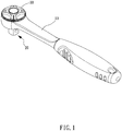
Fig. 1 is a sketch of a first ratchet wrench structure; -
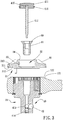
Fig. 2 is a breakdown drawing of the ratchet wrench ofFig. 1 ; -
Fig. 3 is a schematic drawing showing assembling of the ratchet wrench ofFig. 1 ; -
Fig. 4 is the other schematic drawing showing assembling of the ratchet wrench ofFig. 1 ; -
Fig. 5 is a drawing showing the ratchet wrench ofFig. 1 in use; -
Fig. 6 is the other drawing showing the ratchet wrench ofFig. 1 in use; and -
Fig. 7 is a sketch of the preferred embodiment of the present invention. - Please refer to
Figs. 1 to 4 for a first ratchet wrench structure, including amain body 10, aratcheting head 20, aseal cap 30 and alatching mechanism 40. - The
main body 10 includes a receivingslot 11 and a firstanti-dust portion 12 annularly disposed around outside thereceiving slot 11. A circumferential wall inside thereceiving slot 11 is provided with aratcheting portion 13 therearound. Specifically, themain body 10, thereceiving slot 11, the firstanti-dust portion 12 and theratcheting portion 13 can be made of metal (for example, aluminum alloy, steel and others) and integrally formed through melting or forging. More specifically, the firstanti-dust portion 12 includes a firstannular face 121 and ananti-dust wall 122. The firstannular face 121 extends from an outer circumferential face of themain body 10 toward thereceiving slot 11, and the anti-dust wall protrudes from an inner annular edge of the first annular face. In an alternative design, the firstannular face 121 can be a radial slanted face, for example, there can be an included angle between the firstannular face 121 and a cross-section of thereceiving slot 11. - The
ratcheting head 20 is rotatably disposed in thereceiving slot 11, and theratcheting head 20 includes amounting protrusion 21. In this design, theratcheting head 20 is formed with a restrictingtooth member 22 selectively meshable with theratcheting portion 13. More specifically, the restrictingtooth member 22 includes a restrictingtooth portion 23 for being meshed with theratcheting portion 13, and the restrictingtooth portion 23 includes a plurality of protruding teeth. Preferably, the restrictingtooth member 22 can be made of carbon steel so as to allow the restrictingtooth member 22 to have high wear resistance and rigidity. - The restricting
tooth member 22 can restrict the rotating direction of the ratchetinghead 20, for example, the restrictingtooth member 22 can make the restrictingtooth member 22 controllably engaged with the ratchetinghead 20 through a positioning mechanism. Furthermore, in this design, the positioning mechanism, for example, includes anelastic member 50 and aprotruding column 51 disposed through theelastic member 50. Theelastic member 50 is assembled to the restrictingtooth member 22, and theprotruding column 51 can connect to theseal cap 30. Through rotating theseal cap 30 and theprotruding column 51, the protruding column abuts against an end of theelastic member 50 and to drive theelastic member 50. The restrictingtooth member 22 is positioned to a predetermined position to be meshed with theratcheting portion 13 through co-moving with theelastic member 50. The restrictingtooth member 20 is meshed with theratcheting portion 13 to actuate theratcheting head 20 so as to restrict the rotating direction of theratcheting head 20. - The
seal cap 30 is capped on themain body 10 and is located above theratcheting head 20. Theseal cap 30 has a secondanti-dust portion 31 whose structure corresponds to a structure of the firstanti-dust portion 12 and asliding slot 32 disposed through theseal cap 30. The secondanti-dust portion 31 includes anannular protrusion 311 facing the firstannular face 121 and anannular recession 312 adjacent to an inner annular edge of theannular protrusion 311. Theannular recession 312 and theanti-dust wall 122 are engaged with each other, and theannular protrusion 311 and theanti-dust wall 122 are radially disposed neighboring to each other. A blockingedge 33 is provided at an end of the sliding slot and extends radially inward. Theannular protrusion 311 has a secondannular face 313 whose shape corresponds to a shape of the firstannular face 121; therefore, when the firstanti-dust portion 12 and the secondanti-dust portion 31 are assemble with each other, the first and secondannular faces annular faces annular faces seal cap 30 and themain body 10 to operate smoothly (for example, to allow theseal cap 30 to rotate relative to the main body 10) and prevent foreign objects (such as dust) from entering thereceiving slot 11 of the ratchet wrench. It is to be noted that theanti-dust wall 122 and theannular recession 312 which are mutually engaged can prevent particles or foreign matters from entering the ratchet wrench so as to elevate anti-dust effect. In addition, the ratchet wrench further includes ascrew member 60 screwed between theseal cap 30 and theratcheting head 20, and theseal cap 30 and theratcheting head 20 connect to each through thescrew member 60. - The
latching mechanism 40 includes apushing assembly 41 and anabutting member 42. The pushingassembly 41 includes apressing board 411, and a circumferential face of the pressingboard 411 is protrudingly disposed a restrictingmember 416 thereaorund. The restrictingmember 416 abuts against and is stuck with the blockingedge 33 so as to restrict thepressing board 411 in thesliding slot 32. In this design, the pushingassembly 41 further includes arod 412, arolling bead 413 and an elastic abuttingmember 414 elastically abuts against between therolling bead 413 and an inner wall of theratcheting head 20. A first end of therod 412 is slidably inserted in theratcheting head 20 and abuts against therolling bead 413, and therolling bead 413 is selectively abuts against the abuttingmember 42. Thepressing board 411 is disposed at a second end of therod 412. It is to be noted that the second end of therod 412 is annularly formed with a restrictingslot 415. Therestricting slot 415 is recessed on thepressing board 411, and therestricting slot 415 is entirely encompassed by thepressing board 411 and thepressing board 411 is partly embedded in therestricting slot 415 so as to produce a preferable connecting strength between thepressing board 411 and therod 412. In this design, the restrictingmember 416 is an engaging member, and the restrictingmember 416 overlaps a part of the blockingedge 33 of thesliding slot 32 along an axial direction. Specifically, thepressing board 411 is pressed to be assembled in thesliding slot 32. Preferably, a top end edge of thesliding slot 32 is annularly formed with afillet 34 to make the pressing and mounting process easier. Thescrew member 60 further includes a throughhole 61 for therod 412 to dispose therethrough so as to allow therod 412 to actuate via the throughhole 61. - Please refer to
Figs. 5 and6 . In actual use, thepushing assembly 41 is inserted in theratcheting head 20 and movable to be in an abutting position P1 and a releasing position P2. The abuttingmember 42 is movably disposed in the ratchetinghead 20 and selectively partly protrudes outside themounting protrusion 21. Furthermore, the pushingassembly 41 is able to move from the abutting position P1 to the releasing position P2 through pressing thepressing board 411 from outside. When the pushingassembly 41 is in the abutting position P1, the pushingassembly 41 abuts against the abuttingmember 42 and partly protrudes outside the mountingprotrusion 21. When the pushingassembly 41 is in the releasing position P2, the pushingassembly 41 is disengaged from the abuttingmember 42, and the abuttingmember 42 can retreat back into the mountingprotrusion 21. For example, the abuttingmember 42 can be a steel bead, and a part of the steel bead can protrude outside or retreat back into the mountingprotrusion 21. More specifically, an elastic force of the elastic abuttingmember 414 is transmitted to thepressing board 411 through the rollingbead 413 and therod 412, and the restrictingmember 416 and the blockingedge 33 are engaged with each other to allow thepressing board 411 to stay in a third position P3 normally. When the pushingassembly 41 is in the abutting position P1, thepressing board 411 is in the third position P3, and the abuttingmember 42 partly protrudes outside the mountingprotrusion 21 for being assembled to and engaged with a tool (for example, a socket) and preventing the tool from falling off. For example, thepressing board 411 can be pushed and pressed by a force and slides to a fourth position P4. When the pushingassembly 41 is in the releasing position P2, thepressing board 411 is in the fourth position P4, and the abuttingmember 42 retreats back into the mountingprotrusion 21; hence, the tool can be taken off from the mountingprotrusion 21. - Please refer to
Fig. 7 for the preferred embodiment of the ratchet wrench of the present invention. The ratchet wrench includes a main body. The main body includes a receiving slot and a firstanti-dust portion 12a annularly arranged around outside the receiving slot, and the firstanti-dust portion 12a includes a firstannular face 121a and an anti-dust wall 122a. The firstannular face 121a extends from the outer circumferential face of the main body toward the receiving slot, and the firstannular face 121a can be a radial slanted face. The anti-dust wall 122a protrudes from an inner annular edge of the firstannular face 121a. The ratchet wrench further includes a ratcheting head rotatably disposed in the receiving slot and has a secondanti-dust portion 31a whose shape corresponds to a shape of the firstanti-dust portion 12a and a mounting protrusion, wherein the secondanti-dust portion 31a includes anannular protrusion 311a facing the firstannular face 121a and anannular recession 312a adjacent to an inner annular edge of theannular protrusion 311a. Theannular recession 312a and the anti-dust wall 122a are engaged with each other, and theannular protrusion 311a and the anti-dust wall 122a are radially disposed neighboring to each other. Theannular protrusion 311a has a secondannular face 313 a whose shape corresponds to the shape of the firstannular face 121a; therefore, when the firstanti-dust portion 12a and the secondanti-dust portion 31a are assembled with each other, the first and secondannular faces annular recession 312a which are mutually engaged can prevent particles or foreign matters from entering the ratchet wrench and elevate anti-dust effect. The ratchet wrench includes a seal cap capped on the main body and located above the ratcheting head. The ratchet wrench has a sliding slot disposed through the seal cap, and a blocking edge is provided at an end of the sliding slot and extends radially inward. The ratchet wrench further includes a restricting tooth member, a positioning mechanism and a latching mechanism as the same as the structure mentioned above. - Given the above, a ratchet wrench of the present invention is controlled by pressing and is provided for a tool to be assembled or engaged therewith. With the present invention, the tool can be prevented from falling off during the operating process and can be removed easily after operating. In addition, the design of an annular face and an anti-dust wall can produce anti-dust effect and keep a mechanism protected and clean.
Claims (5)
- A ratchet wrench, including:a main body (10), including a receiving slot (11);a ratcheting head (20) including a ratcheting body, rotatably disposed in the receiving slot (11), including a mounting protrusion (21);a seal cap (30), capped on the main body (10) and located above the ratcheting head (20), having a sliding slot (11) disposed through the seal cap (30),a latching mechanism (40), including a pushing assembly (41) and an abutting member (42), wherein the pushing assembly (41) is inserted in the ratcheting head (20) and movable to be in an abutting position (P1) and a releasing position (P2), the pushing assembly (41) includes a pressing board (411), the abutting member (42) is movably disposed in the ratcheting head (20) and selectively protrudable outside the mounting protrusion (21), the pushing assembly (41) is able to move from the abutting position (P1) to the releasing position (P2) through pressing the pressing board (411) from outside, when the pushing assembly (41) is in the abutting position (P1), the pushing assembly (41) abuts against the abutting member (42) and partly protrudes outside the mounting protrusion (21), when the pushing assembly (41) is in the releasing position (P2), the pushing assembly (41) is disengaged from the abutting member (42), and the abutting member (42) is retreatable back into the mounting protrusion (21);characterized in thata blocking edge (33) is provided at an end of the sliding slot (32) and extending radially inward;a circumferential face of the pressing board (411) is protrudingly disposed a restricting member (416) therearound, wherein the restricting member (416) and the blocking edge (33) abut against and are stuck with each other to restrict the pressing board (411) in the sliding slot (32);the main body (10) includes a first anti-dust portion (12a) annularly arranged around outside the receiving slot (11), the first anti-dust portion (12a) including a first annular face (121a) and an anti-dust wall (122a), the first annular face (121a) extending from an outer circumferential face of the main body (10) toward the receiving slot (11), the anti-dust wall (122a) protruding from an inner annular edge of the first annular face (121a); and the ratcheting head (20) further includes a second anti-dust portion (31a) whose shape corresponds to a shape of the first anti-dust portion (12a), wherein the second anti-dust portion (31a) includes an annular protrusion (311a) facing the first annular face (121a) and an annular recession (312a) adjacent to an inner annular edge of the annular protrusion (311a), the annular recession (312a) being just adjacent to an outer wall of the ratcheting body, wherein one lateral wall of the annular recession (312a) is formed by the outer wall of the ratcheting body, wherein the annular recession (312a) and the anti-dust wall (122a) are engaged with each other, and the annular protrusion (311a) and the anti-dust wall (122a) are radially disposed neighboring to each other.
- The ratchet wrench of claim 1, wherein a circumferential wall inside the receiving slot (11) is provided with a ratcheting portion (13) arranged there around, the ratcheting head (20) is formed with a restricting tooth member (23) selectively meshable with the ratcheting portion (13), and a rotating direction of the ratcheting head (20) is restrictable by the restricting tooth member (23).
- The ratchet wrench of claim 1, wherein the pushing assembly (41) further includes a rod (412), a rolling bead (413) and an elastic abutting member (414) elastically abuts against between the rolling bead (413) and an inner wall of the ratcheting head (20), a first end of the rod (412) is slidably inserted in the ratcheting head (20) and abuts against the rolling bead (413), the rolling bead (413) selectively abuts against the abutting member (42), and the pressing board (411) is disposed at a second end of the rod (412).
- The ratchet wrench of claim 1, wherein the restricting member (416) is an engaging member, and the engaging member overlaps a part of the blocking edge (33) along an axial direction.
- The ratchet wrench of claim 3, further including a screw member (60) screwed between the seal cap (30) and the ratcheting head (20), wherein the screw member (60) includes a through hole for the rod (412) to dispose therethrough, the second end of the rod (412) is annularly formed with a restricting slot (415), the restricting slot (415) is recessed on the pressing board (411), and the restricting slot (415) is entirely encompassed by the pressing board (411) and the pressing board (411) is partly embedded in the restricting slot (415).
Applications Claiming Priority (1)
| Application Number | Priority Date | Filing Date | Title |
|---|---|---|---|
| TW103134580A TWI530368B (en) | 2014-10-03 | 2014-10-03 | Ratchet wrench |
Publications (2)
| Publication Number | Publication Date |
|---|---|
| EP3002083A1 EP3002083A1 (en) | 2016-04-06 |
| EP3002083B1 true EP3002083B1 (en) | 2019-09-11 |
Family
ID=51845318
Family Applications (1)
| Application Number | Title | Priority Date | Filing Date |
|---|---|---|---|
| EP14191190.9A Active EP3002083B1 (en) | 2014-10-03 | 2014-10-31 | Ratchet socket wrench |
Country Status (2)
| Country | Link |
|---|---|
| EP (1) | EP3002083B1 (en) |
| TW (1) | TWI530368B (en) |
Families Citing this family (1)
| Publication number | Priority date | Publication date | Assignee | Title |
|---|---|---|---|---|
| TWI551403B (en) * | 2015-12-15 | 2016-10-01 | Apex Tool Hk Ltd | A ratchet wrench with a dustproof structure |
Citations (1)
| Publication number | Priority date | Publication date | Assignee | Title |
|---|---|---|---|---|
| TWM477352U (en) * | 2013-12-31 | 2014-05-01 | Kabo Tool Co | Antifouling structure of tool |
Family Cites Families (8)
| Publication number | Priority date | Publication date | Assignee | Title |
|---|---|---|---|---|
| US5305670A (en) * | 1989-07-28 | 1994-04-26 | Gregory Fossella | Adjustable wrench |
| US5916339A (en) * | 1997-05-23 | 1999-06-29 | Facom | One-way drive mechanism and corresponding ratchet tool |
| IT1292554B1 (en) * | 1997-06-11 | 1999-02-08 | Intercable Srl | DRIVING PANEL FOR TOOLS WITH LOCKABLE COUPLING |
| DE29721275U1 (en) * | 1997-12-01 | 1998-01-15 | Hsieh, Chih-Ching, Fong Yuan, Taichung | Removable ratchet socket wrench |
| US5921158A (en) * | 1997-12-04 | 1999-07-13 | Snap-On Tools Company | Sealed reversible ratchet wrench |
| US6260448B1 (en) * | 1999-12-21 | 2001-07-17 | Hand Tool Design Corporation | Top load ratchet wrench |
| US7066055B1 (en) * | 2004-12-30 | 2006-06-27 | Yi-Min Lee | Ratchet wrench that can release socket rapidly |
| PL2737977T3 (en) * | 2012-11-30 | 2016-06-30 | Matatakitoyo Tool Co Ltd | One-Way Torque Tool |
-
2014
- 2014-10-03 TW TW103134580A patent/TWI530368B/en active
- 2014-10-31 EP EP14191190.9A patent/EP3002083B1/en active Active
Patent Citations (1)
| Publication number | Priority date | Publication date | Assignee | Title |
|---|---|---|---|---|
| TWM477352U (en) * | 2013-12-31 | 2014-05-01 | Kabo Tool Co | Antifouling structure of tool |
Also Published As
| Publication number | Publication date |
|---|---|
| TWI530368B (en) | 2016-04-21 |
| TW201505774A (en) | 2015-02-16 |
| EP3002083A1 (en) | 2016-04-06 |
Similar Documents
| Publication | Publication Date | Title |
|---|---|---|
| US8943930B2 (en) | Wrench device | |
| US11285589B2 (en) | Socket | |
| US20150258666A1 (en) | Socket Wrench | |
| US9914205B2 (en) | Auxiliary handle and electric tool having the same | |
| US20120284982A1 (en) | Drawing device | |
| US20120213608A1 (en) | Self-Locking Screwing Attachment Device And Assembly Provided With Same | |
| US20150290783A1 (en) | Wrench tool with positioning device | |
| US8943928B2 (en) | Ratchet wheel wrench | |
| JP2013510273A5 (en) | ||
| EP2696085A1 (en) | Anti-seizing bolt | |
| EP3479959A1 (en) | Ratchet wrench | |
| US20170282338A1 (en) | Adjusting assembly of brake cylinder installation device | |
| US20190283221A1 (en) | Two-stage universal joint | |
| US20160193723A1 (en) | Tool Head | |
| EP3002083A1 (en) | Ratchet socket wrench | |
| US9486901B2 (en) | Socket wrench | |
| US10145406B2 (en) | Self-locking screwing attachment devices and assemblies provided with same | |
| JP3219779U (en) | Bidirectional telescopic socket | |
| TWI518254B (en) | Avoid loose bolts | |
| CN201183126Y (en) | A new type of chuck | |
| JP6543806B2 (en) | Impact tool | |
| TW201501876A (en) | Ratchet wrench | |
| WO2020031252A1 (en) | Lock washer and fastening structure | |
| TW201600262A (en) | Push-on quick release screwdriver | |
| US20110308021A1 (en) | Pipe Deburrer with Replaceable Tool Head |
Legal Events
| Date | Code | Title | Description |
|---|---|---|---|
| PUAI | Public reference made under article 153(3) epc to a published international application that has entered the european phase |
Free format text: ORIGINAL CODE: 0009012 |
|
| 17P | Request for examination filed |
Effective date: 20141222 |
|
| AK | Designated contracting states |
Kind code of ref document: A1 Designated state(s): AL AT BE BG CH CY CZ DE DK EE ES FI FR GB GR HR HU IE IS IT LI LT LU LV MC MK MT NL NO PL PT RO RS SE SI SK SM TR |
|
| AX | Request for extension of the european patent |
Extension state: BA ME |
|
| STAA | Information on the status of an ep patent application or granted ep patent |
Free format text: STATUS: EXAMINATION IS IN PROGRESS |
|
| 17Q | First examination report despatched |
Effective date: 20170224 |
|
| GRAP | Despatch of communication of intention to grant a patent |
Free format text: ORIGINAL CODE: EPIDOSNIGR1 |
|
| STAA | Information on the status of an ep patent application or granted ep patent |
Free format text: STATUS: GRANT OF PATENT IS INTENDED |
|
| INTG | Intention to grant announced |
Effective date: 20190319 |
|
| GRAS | Grant fee paid |
Free format text: ORIGINAL CODE: EPIDOSNIGR3 |
|
| GRAA | (expected) grant |
Free format text: ORIGINAL CODE: 0009210 |
|
| STAA | Information on the status of an ep patent application or granted ep patent |
Free format text: STATUS: THE PATENT HAS BEEN GRANTED |
|
| AK | Designated contracting states |
Kind code of ref document: B1 Designated state(s): AL AT BE BG CH CY CZ DE DK EE ES FI FR GB GR HR HU IE IS IT LI LT LU LV MC MK MT NL NO PL PT RO RS SE SI SK SM TR |
|
| REG | Reference to a national code |
Ref country code: GB Ref legal event code: FG4D |
|
| REG | Reference to a national code |
Ref country code: CH Ref legal event code: EP |
|
| REG | Reference to a national code |
Ref country code: AT Ref legal event code: REF Ref document number: 1177835 Country of ref document: AT Kind code of ref document: T Effective date: 20190915 |
|
| REG | Reference to a national code |
Ref country code: DE Ref legal event code: R096 Ref document number: 602014053339 Country of ref document: DE Ref country code: IE Ref legal event code: FG4D |
|
| REG | Reference to a national code |
Ref country code: SE Ref legal event code: TRGR |
|
| REG | Reference to a national code |
Ref country code: NL Ref legal event code: MP Effective date: 20190911 |
|
| REG | Reference to a national code |
Ref country code: LT Ref legal event code: MG4D |
|
| PG25 | Lapsed in a contracting state [announced via postgrant information from national office to epo] |
Ref country code: LT Free format text: LAPSE BECAUSE OF FAILURE TO SUBMIT A TRANSLATION OF THE DESCRIPTION OR TO PAY THE FEE WITHIN THE PRESCRIBED TIME-LIMIT Effective date: 20190911 Ref country code: HR Free format text: LAPSE BECAUSE OF FAILURE TO SUBMIT A TRANSLATION OF THE DESCRIPTION OR TO PAY THE FEE WITHIN THE PRESCRIBED TIME-LIMIT Effective date: 20190911 Ref country code: BG Free format text: LAPSE BECAUSE OF FAILURE TO SUBMIT A TRANSLATION OF THE DESCRIPTION OR TO PAY THE FEE WITHIN THE PRESCRIBED TIME-LIMIT Effective date: 20191211 Ref country code: FI Free format text: LAPSE BECAUSE OF FAILURE TO SUBMIT A TRANSLATION OF THE DESCRIPTION OR TO PAY THE FEE WITHIN THE PRESCRIBED TIME-LIMIT Effective date: 20190911 Ref country code: NO Free format text: LAPSE BECAUSE OF FAILURE TO SUBMIT A TRANSLATION OF THE DESCRIPTION OR TO PAY THE FEE WITHIN THE PRESCRIBED TIME-LIMIT Effective date: 20191211 |
|
| PG25 | Lapsed in a contracting state [announced via postgrant information from national office to epo] |
Ref country code: ES Free format text: LAPSE BECAUSE OF FAILURE TO SUBMIT A TRANSLATION OF THE DESCRIPTION OR TO PAY THE FEE WITHIN THE PRESCRIBED TIME-LIMIT Effective date: 20190911 Ref country code: RS Free format text: LAPSE BECAUSE OF FAILURE TO SUBMIT A TRANSLATION OF THE DESCRIPTION OR TO PAY THE FEE WITHIN THE PRESCRIBED TIME-LIMIT Effective date: 20190911 Ref country code: GR Free format text: LAPSE BECAUSE OF FAILURE TO SUBMIT A TRANSLATION OF THE DESCRIPTION OR TO PAY THE FEE WITHIN THE PRESCRIBED TIME-LIMIT Effective date: 20191212 Ref country code: LV Free format text: LAPSE BECAUSE OF FAILURE TO SUBMIT A TRANSLATION OF THE DESCRIPTION OR TO PAY THE FEE WITHIN THE PRESCRIBED TIME-LIMIT Effective date: 20190911 Ref country code: AL Free format text: LAPSE BECAUSE OF FAILURE TO SUBMIT A TRANSLATION OF THE DESCRIPTION OR TO PAY THE FEE WITHIN THE PRESCRIBED TIME-LIMIT Effective date: 20190911 |
|
| REG | Reference to a national code |
Ref country code: AT Ref legal event code: MK05 Ref document number: 1177835 Country of ref document: AT Kind code of ref document: T Effective date: 20190911 |
|
| PG25 | Lapsed in a contracting state [announced via postgrant information from national office to epo] |
Ref country code: RO Free format text: LAPSE BECAUSE OF FAILURE TO SUBMIT A TRANSLATION OF THE DESCRIPTION OR TO PAY THE FEE WITHIN THE PRESCRIBED TIME-LIMIT Effective date: 20190911 Ref country code: IT Free format text: LAPSE BECAUSE OF FAILURE TO SUBMIT A TRANSLATION OF THE DESCRIPTION OR TO PAY THE FEE WITHIN THE PRESCRIBED TIME-LIMIT Effective date: 20190911 Ref country code: EE Free format text: LAPSE BECAUSE OF FAILURE TO SUBMIT A TRANSLATION OF THE DESCRIPTION OR TO PAY THE FEE WITHIN THE PRESCRIBED TIME-LIMIT Effective date: 20190911 Ref country code: AT Free format text: LAPSE BECAUSE OF FAILURE TO SUBMIT A TRANSLATION OF THE DESCRIPTION OR TO PAY THE FEE WITHIN THE PRESCRIBED TIME-LIMIT Effective date: 20190911 Ref country code: NL Free format text: LAPSE BECAUSE OF FAILURE TO SUBMIT A TRANSLATION OF THE DESCRIPTION OR TO PAY THE FEE WITHIN THE PRESCRIBED TIME-LIMIT Effective date: 20190911 Ref country code: PT Free format text: LAPSE BECAUSE OF FAILURE TO SUBMIT A TRANSLATION OF THE DESCRIPTION OR TO PAY THE FEE WITHIN THE PRESCRIBED TIME-LIMIT Effective date: 20200113 Ref country code: PL Free format text: LAPSE BECAUSE OF FAILURE TO SUBMIT A TRANSLATION OF THE DESCRIPTION OR TO PAY THE FEE WITHIN THE PRESCRIBED TIME-LIMIT Effective date: 20190911 |
|
| PG25 | Lapsed in a contracting state [announced via postgrant information from national office to epo] |
Ref country code: SK Free format text: LAPSE BECAUSE OF FAILURE TO SUBMIT A TRANSLATION OF THE DESCRIPTION OR TO PAY THE FEE WITHIN THE PRESCRIBED TIME-LIMIT Effective date: 20190911 Ref country code: IS Free format text: LAPSE BECAUSE OF FAILURE TO SUBMIT A TRANSLATION OF THE DESCRIPTION OR TO PAY THE FEE WITHIN THE PRESCRIBED TIME-LIMIT Effective date: 20200224 Ref country code: SM Free format text: LAPSE BECAUSE OF FAILURE TO SUBMIT A TRANSLATION OF THE DESCRIPTION OR TO PAY THE FEE WITHIN THE PRESCRIBED TIME-LIMIT Effective date: 20190911 Ref country code: CZ Free format text: LAPSE BECAUSE OF FAILURE TO SUBMIT A TRANSLATION OF THE DESCRIPTION OR TO PAY THE FEE WITHIN THE PRESCRIBED TIME-LIMIT Effective date: 20190911 |
|
| REG | Reference to a national code |
Ref country code: CH Ref legal event code: PL |
|
| REG | Reference to a national code |
Ref country code: DE Ref legal event code: R097 Ref document number: 602014053339 Country of ref document: DE |
|
| PLBE | No opposition filed within time limit |
Free format text: ORIGINAL CODE: 0009261 |
|
| STAA | Information on the status of an ep patent application or granted ep patent |
Free format text: STATUS: NO OPPOSITION FILED WITHIN TIME LIMIT |
|
| PG2D | Information on lapse in contracting state deleted |
Ref country code: IS |
|
| PG25 | Lapsed in a contracting state [announced via postgrant information from national office to epo] |
Ref country code: DK Free format text: LAPSE BECAUSE OF FAILURE TO SUBMIT A TRANSLATION OF THE DESCRIPTION OR TO PAY THE FEE WITHIN THE PRESCRIBED TIME-LIMIT Effective date: 20190911 Ref country code: LI Free format text: LAPSE BECAUSE OF NON-PAYMENT OF DUE FEES Effective date: 20191031 Ref country code: CH Free format text: LAPSE BECAUSE OF NON-PAYMENT OF DUE FEES Effective date: 20191031 Ref country code: IS Free format text: LAPSE BECAUSE OF FAILURE TO SUBMIT A TRANSLATION OF THE DESCRIPTION OR TO PAY THE FEE WITHIN THE PRESCRIBED TIME-LIMIT Effective date: 20200112 |
|
| REG | Reference to a national code |
Ref country code: BE Ref legal event code: MM Effective date: 20191031 |
|
| 26N | No opposition filed |
Effective date: 20200615 |
|
| PG25 | Lapsed in a contracting state [announced via postgrant information from national office to epo] |
Ref country code: MC Free format text: LAPSE BECAUSE OF FAILURE TO SUBMIT A TRANSLATION OF THE DESCRIPTION OR TO PAY THE FEE WITHIN THE PRESCRIBED TIME-LIMIT Effective date: 20190911 Ref country code: SI Free format text: LAPSE BECAUSE OF FAILURE TO SUBMIT A TRANSLATION OF THE DESCRIPTION OR TO PAY THE FEE WITHIN THE PRESCRIBED TIME-LIMIT Effective date: 20190911 Ref country code: BE Free format text: LAPSE BECAUSE OF NON-PAYMENT OF DUE FEES Effective date: 20191031 |
|
| GBPC | Gb: european patent ceased through non-payment of renewal fee |
Effective date: 20191211 |
|
| PG25 | Lapsed in a contracting state [announced via postgrant information from national office to epo] |
Ref country code: GB Free format text: LAPSE BECAUSE OF NON-PAYMENT OF DUE FEES Effective date: 20191211 Ref country code: IE Free format text: LAPSE BECAUSE OF NON-PAYMENT OF DUE FEES Effective date: 20191031 Ref country code: FR Free format text: LAPSE BECAUSE OF NON-PAYMENT OF DUE FEES Effective date: 20191111 |
|
| PG25 | Lapsed in a contracting state [announced via postgrant information from national office to epo] |
Ref country code: CY Free format text: LAPSE BECAUSE OF FAILURE TO SUBMIT A TRANSLATION OF THE DESCRIPTION OR TO PAY THE FEE WITHIN THE PRESCRIBED TIME-LIMIT Effective date: 20190911 |
|
| PG25 | Lapsed in a contracting state [announced via postgrant information from national office to epo] |
Ref country code: HU Free format text: LAPSE BECAUSE OF FAILURE TO SUBMIT A TRANSLATION OF THE DESCRIPTION OR TO PAY THE FEE WITHIN THE PRESCRIBED TIME-LIMIT; INVALID AB INITIO Effective date: 20141031 Ref country code: MT Free format text: LAPSE BECAUSE OF FAILURE TO SUBMIT A TRANSLATION OF THE DESCRIPTION OR TO PAY THE FEE WITHIN THE PRESCRIBED TIME-LIMIT Effective date: 20190911 |
|
| PG25 | Lapsed in a contracting state [announced via postgrant information from national office to epo] |
Ref country code: TR Free format text: LAPSE BECAUSE OF FAILURE TO SUBMIT A TRANSLATION OF THE DESCRIPTION OR TO PAY THE FEE WITHIN THE PRESCRIBED TIME-LIMIT Effective date: 20190911 |
|
| PG25 | Lapsed in a contracting state [announced via postgrant information from national office to epo] |
Ref country code: MK Free format text: LAPSE BECAUSE OF FAILURE TO SUBMIT A TRANSLATION OF THE DESCRIPTION OR TO PAY THE FEE WITHIN THE PRESCRIBED TIME-LIMIT Effective date: 20190911 |
|
| PGFP | Annual fee paid to national office [announced via postgrant information from national office to epo] |
Ref country code: SE Payment date: 20240828 Year of fee payment: 11 |
|
| PGFP | Annual fee paid to national office [announced via postgrant information from national office to epo] |
Ref country code: LU Payment date: 20241028 Year of fee payment: 11 |
|
| PGFP | Annual fee paid to national office [announced via postgrant information from national office to epo] |
Ref country code: DE Payment date: 20241029 Year of fee payment: 11 |