EP3001924A1 - Sole for a shoe - Google Patents
Sole for a shoe Download PDFInfo
- Publication number
- EP3001924A1 EP3001924A1 EP15187062.3A EP15187062A EP3001924A1 EP 3001924 A1 EP3001924 A1 EP 3001924A1 EP 15187062 A EP15187062 A EP 15187062A EP 3001924 A1 EP3001924 A1 EP 3001924A1
- Authority
- EP
- European Patent Office
- Prior art keywords
- layer
- sole
- mesh
- shoe
- porous mesh
- Prior art date
- Legal status (The legal status is an assumption and is not a legal conclusion. Google has not performed a legal analysis and makes no representation as to the accuracy of the status listed.)
- Granted
Links
Images





Classifications
-
- A—HUMAN NECESSITIES
- A43—FOOTWEAR
- A43B—CHARACTERISTIC FEATURES OF FOOTWEAR; PARTS OF FOOTWEAR
- A43B13/00—Soles; Sole-and-heel integral units
- A43B13/02—Soles; Sole-and-heel integral units characterised by the material
- A43B13/12—Soles with several layers of different materials
- A43B13/122—Soles with several layers of different materials characterised by the outsole or external layer
-
- A—HUMAN NECESSITIES
- A43—FOOTWEAR
- A43B—CHARACTERISTIC FEATURES OF FOOTWEAR; PARTS OF FOOTWEAR
- A43B13/00—Soles; Sole-and-heel integral units
- A43B13/02—Soles; Sole-and-heel integral units characterised by the material
- A43B13/04—Plastics, rubber or vulcanised fibre
-
- A—HUMAN NECESSITIES
- A43—FOOTWEAR
- A43B—CHARACTERISTIC FEATURES OF FOOTWEAR; PARTS OF FOOTWEAR
- A43B13/00—Soles; Sole-and-heel integral units
- A43B13/02—Soles; Sole-and-heel integral units characterised by the material
- A43B13/12—Soles with several layers of different materials
-
- A—HUMAN NECESSITIES
- A43—FOOTWEAR
- A43B—CHARACTERISTIC FEATURES OF FOOTWEAR; PARTS OF FOOTWEAR
- A43B13/00—Soles; Sole-and-heel integral units
- A43B13/14—Soles; Sole-and-heel integral units characterised by the constructive form
- A43B13/18—Resilient soles
- A43B13/181—Resiliency achieved by the structure of the sole
- A43B13/184—Resiliency achieved by the structure of the sole the structure protruding from the outsole
-
- A—HUMAN NECESSITIES
- A43—FOOTWEAR
- A43B—CHARACTERISTIC FEATURES OF FOOTWEAR; PARTS OF FOOTWEAR
- A43B13/00—Soles; Sole-and-heel integral units
- A43B13/14—Soles; Sole-and-heel integral units characterised by the constructive form
- A43B13/22—Soles made slip-preventing or wear-resisting, e.g. by impregnation or spreading a wear-resisting layer
- A43B13/223—Profiled soles
-
- B—PERFORMING OPERATIONS; TRANSPORTING
- B29—WORKING OF PLASTICS; WORKING OF SUBSTANCES IN A PLASTIC STATE IN GENERAL
- B29D—PRODUCING PARTICULAR ARTICLES FROM PLASTICS OR FROM SUBSTANCES IN A PLASTIC STATE
- B29D35/00—Producing footwear
- B29D35/0009—Producing footwear by injection moulding; Apparatus therefor
-
- B—PERFORMING OPERATIONS; TRANSPORTING
- B29—WORKING OF PLASTICS; WORKING OF SUBSTANCES IN A PLASTIC STATE IN GENERAL
- B29D—PRODUCING PARTICULAR ARTICLES FROM PLASTICS OR FROM SUBSTANCES IN A PLASTIC STATE
- B29D35/00—Producing footwear
- B29D35/0054—Producing footwear by compression moulding, vulcanising or the like; Apparatus therefor
-
- B—PERFORMING OPERATIONS; TRANSPORTING
- B29—WORKING OF PLASTICS; WORKING OF SUBSTANCES IN A PLASTIC STATE IN GENERAL
- B29D—PRODUCING PARTICULAR ARTICLES FROM PLASTICS OR FROM SUBSTANCES IN A PLASTIC STATE
- B29D35/00—Producing footwear
- B29D35/12—Producing parts thereof, e.g. soles, heels, uppers, by a moulding technique
- B29D35/122—Soles
Definitions
- the present invention is directed to a sole for a shoe.
- Shoes in particular sports shoes, usually comprise a sole and a shoe upper attached to the sole.
- the sole is usually made from an abrasion-resistant and nonskid material such as rubber or similar and can be provided with a tread to improve traction.
- a sole is also referred to as an outsole, because it engages the ground.
- the outsole can be the only sole provided with the shoe.
- a sole of a shoe can be provided with a midsole arranged on top of the outsole and being made of a shock-absorbing material such as rubber, ethylene vinyl acetate (EVA) or similar.
- EVA ethylene vinyl acetate
- a sole may either comprise just an outsole or may comprise a midsole in addition.
- the soles (i.e. the outsoles or the combination of outsoles and midsoles) of shoes tend to have rather large weights to provide for abrasion-resistance, traction and damping. While the latter properties are desirable, the weight of shoes, especially sports shoes, should be as small as possible to allow for natural motions and, in the case of sports shoes, maximum performance of an athlete. Running shoes for example must be abrasion-resistant and provide damping and traction. However, it is not acceptable, if these objectives can only be fulfilled by increasing the weight of the running shoes to such an extent that the athlete fatigues.
- US 6,782,642 B2 relates to an article of footwear with a sole including a mesh layer at least partially embedded in the sole layer.
- the mesh extends along and is substantially coterminous, i.e. flush, with a bottom surface of the sole layer.
- the mesh provides traction for the wearer and abrasion resistance for the sole.
- US 2,557,946 relates to a nonskid rubber sole with an outer surface formed with transverse ribs spaced apart by transverse grooves. Extending longitudinally preferably within each of the transverse ribs is a helical coil.
- US 5,237,758 is directed to a safety shoe with a shoe upper extending upwardly of the shoe sole.
- the shoe sole includes at least one metallic fabric mesh web projected substantially coextensive through the shoe sole to minimize puncturing and projecting of the shoe sole.
- US 2,364,134 relates to soles for footwear comprising a single sheet of fabric which is filled on at least one side by a plastic material applied thereto.
- the fabric is preferably a woven fabric which is formed of sets of weft and sets of warp threads, some of the latter being of comparatively light weight, but at least one of the sets of warps being of comparatively heavy strong yarns or cords having nubs formed of loops which protrude at least on the side of the fabric which is to form the tread of the sole.
- US 2,333,303 is directed to a shoe having an impregnated fabric.
- the fabric is impregnated from one surface thereof and partially therethrough with a flexible adhesive binder.
- the impregnating material may comprise any flexible adhesive binder including rubber, latex, rubber compositions, synthetic rubber, and other plastic materials.
- US 6,032,388 relates to an outsole for a shoe formed from a thin, flexible, nonporous and inelastic material having a pattern of perforations through it, and a plurality of tread elements of a hard, wear-resistant material molded onto a first side of the sheet material by a process in which the tread forming material is injected through the perforations in a manner such that at least some of the resultant tread elements have anchoring portions extending through the perforations from an opposite second side of the sheet material, a portion of the sheet material around the perforations being held between the tread elements and the anchoring portions.
- the soles for shoes known in the prior art are comparatively heavy in order to provide durability, stability and traction. It is therefore the underlying problem of the present invention to provide for a sole for a shoe, which is lightweight, yet abrasion-resistant and durable and provides for good traction.
- a further object of the invention is to provide a shoe, which is lightweight, yet abrasion-resistant and durable and provides for good traction and stability for the foot of a wearer.
- a sole for a shoe comprising a porous mesh and a continuous first layer arranged at least partially on a first side of the porous mesh, wherein the first layer penetrates the porous mesh at least partially to form a tread structure on a second side of the porous mesh opposite the first side, and wherein the first layer and the porous mesh are bonded at least in an area where the tread structure is formed.
- the inventive shoe sole becomes very stable and durable. These properties are further improved by having the first layer penetrate the porous mesh at least partially. In this way, a very stable and secure bond is achieved between the mesh and the first layer.
- less material e.g. rubber
- the shoe sole is advantageously lightweight. Furthermore, as less material is needed, the manufacturing costs are reduced as well.
- the shoe sole provides for maximum traction. This is achieved by having the first layer form a tread structure where it penetrates the porous mesh. Thus, shearing and tension forces during use are dissipated by the tread structure and the mesh.
- the embedded mesh which is in immediate contact with the tread structure provides the shoe sole with a very high elastic modulus (ratio of stress over strain) and a very high shear modulus (response to shear stress). Again, material and costs can be saved compared to conventional shoe soles to achieve these advantages.
- Sole in the context of the present invention is understood as either an outsole or a combination of outsole and midsole.
- the sole may comprise a second layer arranged on the second side of the porous mesh, wherein the second layer comprises at least one aperture in which the tread structure is arranged at least partially, and wherein the second layer and the first layer are bonded at least partially.
- the second layer provides further support for the tread structure and adds to the overall stability and durability of the sole by bonding at least partially to the first layer.
- Such an arrangement is especially advantageous for curved soles.
- the sole may comprise a continuous third layer arranged on the first layer comprising a different material than the first layer, wherein the third layer and the first layer are bonded at least partially.
- the third layer adds to the overall stability of the sole.
- the third layer may provide further functions to the sole, e.g. damping or thermal insulation.
- the first layer may be made of rubber. Rubber is inexpensive and can be easily formed e.g. by molding under heat and / or pressure. Furthermore, rubber provides for abrasion and skid resistance.
- the first layer may be made of a thermoset or a thermoplastic material.
- the mesh may be made of metal, plastic, fabric or textile. These materials provide the sole with stability, durability and high shearing and elastic moduli.
- the second layer may be made of rubber. As explained above, rubber is inexpensive and can be easily formed e.g. by molding under heat and / or pressure. Furthermore, rubber provides for abrasion and skid resistance.
- the third layer may be made of ethylene vinyl acetate, EVA.
- EVA has good damping properties and, thus advantageously avoids or at least decreases shocks which occur especially during sports such as running or basketball.
- the EVA layer may be co-molded or injection molded with the first layer and the mesh after the first layer with the mesh has cured.
- An integrated EVA layer in the sole is especially advantageous for flat soles.
- the tread structure may comprise tread elements. Such tread elements engage the ground and discharge forces during use immediately to the mesh.
- the average size of the mesh openings formed by mesh fibers may be smaller than the average size of the tread elements. In this way, each tread element penetrates a large number of mesh openings resulting in a very stable and durable connection of the tread elements with the mesh. "Size” in this context is understood as diameter or length depending on whether the mesh openings and / or tread elements have a more round or elongated shape.
- the tread elements may have gaps in between, and the porous mesh may be visible through the gaps.
- Such an arrangement may not only add to the overall visual appearance of the sole, but may also result in a deeper profile of the sole, thus increasing traction especially on muddy surfaces or snow.
- the material of the first layer may fill the mesh openings of the porous mesh in the area of the tread structure at least partially. In this way, a stable bond is achieved between the tread elements and the mesh.
- the sole may be configured to be used for a sports shoe.
- the sports shoe may be a running or tennis shoe.
- a lightweight, yet durable, abrasion-resistant and non-skid sole is important.
- a further aspect of the present invention relates to a shoe, comprising a sole as described above and a shoe upper connected to the sole.
- the mesh may extend into the upper.
- the connection between the upper and the sole may be made very strong. Forces may be discharged from the upper to the ground directly via the mesh and the tread structure immediately connected thereto.
- the mesh may form a part of the upper.
- the mesh may be integrated into the upper with the advantages described in the previous paragraph.
- such a construction may add to the overall visual appearance of the sports shoe.
- Yet another aspect of the present invention relates to a method of manufacturing a sole as described above, comprising the steps of providing the porous mesh, arranging the continuous first layer at least partially on the first side of the porous mesh, and molding the first layer and the porous mesh, such that the first layer penetrates the porous mesh at least partially to form the tread structure on the second side of the porous mesh opposite the first side, wherein the first layer and the porous mesh are bonded at least in an area where the tread structure is formed.
- the step of molding may comprise compression molding or injection molding.
- Compression molding is a rather simple method wherein the shoe sole is placed in a mold and formed under pressure and / or heat. With injection molding, the mesh is placed in a mold cavity and the material which is to form the first layer is forced in molten form into the mold cavity. This process can be rather easily automated to achieve a high output of soles.
- the method may further comprise the steps of providing a second layer arranged on the second side of the porous mesh, wherein the second layer comprises at least one aperture in which the tread structure is arranged at least partially.
- the second layer provides further support for the tread structure and adds to the overall stability and durability of the sole by bonding at least partially to the first layer.
- the method may further comprise the steps of providing a continuous third layer arranged on the first layer comprising a different material than the first layer, and bonding the third layer and the first layer at least partially.
- the third layer adds to the overall stability of the sole.
- the third layer may provide further functions to the sole, e.g. damping or thermal insulation.
- a still further aspect of the present invention relates to a method of manufacturing a shoe.
- the method may comprise the steps of providing the sole described above, and connecting the shoe upper to the sole.
- the method may further comprise the step of connecting the shoe upper to the sole via the mesh.
- Figures 1a and 1b show an exemplary embodiment of a sole 100 for a shoe according to the present invention.
- Fig. 1a is a plan view of the sole 100 from below, i.e. from the ground engaging side
- Fig. 1b is a plan view from above, i.e. from the side opposite the ground engaging side where the shoe upper (not shown in figures 1a and 1b ) would be located.
- the sole 100 is generally configured to be used for a shoe, in particular a sports shoe such as a running or tennis shoe, but can be used for other kinds of sports such as basketball, soccer, cycling, volleyball, etc. as well.
- the sole 100 may be an outsole or a combination of an outsole and a midsole.
- the sole 100 comprises a porous mesh 101.
- the porous mesh is a textile mesh having a relatively coarse structure, i.e. the mesh openings are rather wide, having a diameter of roughly 1.4 mm. In general, the mesh openings can have a different diameter, such as 1.2 mm to 6 mm.
- the mesh 101 is a textile made from polyester fibers. Other meshes could be used, e.g. a metal or fabric mesh.
- the mesh 101 is porous, i.e. the openings of the mesh 101 are penetrable by or permeable to fluid or liquid substances or materials. More specifically, fluid or liquid substances or materials may penetrate the mesh from a first side of the mesh to reach a second side of the mesh opposite the first side.
- the sole 100 also comprises a continuous first layer 102 arranged at least partially on a first side of the porous mesh 101.
- the first layer 102 may be made of rubber, but any other suitable material may be used.
- the continuous first layer 102 is arranged at least partially on top of the porous mesh 101.
- the porous mesh 101 is visible in Fig. 1b for example in the heel portion of the sole 100, but need not be visible from above at all, i.e. the first layer 102 may completely cover the porous mesh 101 on the first side of the porous mesh 101.
- the first layer 102 may be arranged on only a portion of the porous mesh 101. Conversely, there may be a portion of the first layer 102 being not arranged on the porous mesh 101.
- the porous mesh 101 and the first layer 102 may generally be in an overlapping configuration.
- the first layer 102 penetrates the porous mesh 101 at least partially to form a tread structure 103 on a second side of the porous mesh opposite the first side.
- the material forming the tread structure 103 in Fig. 1a is material of the first layer 102 which has penetrated the porous mesh 101 in the area where the tread structure 103 is formed.
- the porous mesh 101 is embedded in the first layer where the tread structure is formed.
- the material of the first layer 102 fills the mesh openings of the porous mesh 102 in the area of the tread structure at least partially. In this way, the first layer 102 and the porous mesh 101 are bonded at least in an area where the tread structure 103 is formed.
- the average size of the mesh openings formed by mesh fibers is smaller than the average size of the tread elements of the tread structure 103.
- the diameter of a mesh opening is significantly smaller than the length of the elongated tread elements.
- the tread structure 103 may have any suitable form to allow for good traction of the sole.
- a tread structure 103 is shown to have tread elements of an elongated shape, wherein each tread element has a zigzag arrangement and each tread element runs parallel to an adjacent tread element.
- the shape, size and arrangement of tread elements can generally be different.
- the tread elements can be nub-shaped, star-shaped or the like.
- tread elements may be separate from each other or may be connected.
- the shape, size and arrangement of the tread elements may vary across the sole.
- the tread elements may be protruding to a greater extent in the areas of the sole with higher stress during use.
- the tread elements may have a larger size in one area of the sole, e.g. in the heel portion, than in another area of the sole, e.g. in the toe portion.
- the tread elements 103 have gaps in between, and the porous mesh 101 is visible through the gaps.
- the tread structure 103 may also be arranged such that the mesh 101 is not visible.
- the sole 100 comprises a second layer 104 arranged on the second side of the porous mesh 101.
- the second layer 104 has a ring-like shape and comprises an aperture in which the tread structure is arranged.
- the second layer 104 and the first layer 102 are bonded at least partially.
- the first layer 102 and the second layer 104 are both made from rubber. Thus, both layers form a tight and stable bond when being molded for example.
- the second layer 104 is optional.
- the sole 100 may also comprise a continuous third layer 201arranged on the first layer 102 comprising a different material than the first layer 102, for example ethylene vinyl acetate, EVA.
- a different material for example ethylene vinyl acetate, EVA.
- EVA ethylene vinyl acetate
- Another example is polyurethane (PU) which is injected on top of the first layer 102.
- the third layer and the first layer 102 may be bonded at least partially.
- Fig. 3 shows another exemplary embodiment of a sole 100 according to the invention in which the porous mesh 101 extends throughout the entire sole 100.
- the mesh 101 extends from the toe portion of the sole 100 via the midfoot portion to the heel portion over the entire width of the sole 100.
- Fig. 4 shows a further exemplary embodiment of a sole 100 according to the present invention.
- the mesh 101 is folded in the midfoot portion of the sole 100, so that this folded mesh 101 replaces or supplements, i.e. supports a tread element.
- folds may be arranged at different locations as well, for example in the forefoot or heel portion of the sole.
- the number of folds of the mesh 101 may vary.
- Fig. 5 shows a bottom view of a shoe 500 according to the invention.
- the shoe 500 comprises a sole 100 as discussed above and an upper 501.
- the upper 501 is connected to the sole 100 for example via welding, sewing or gluing.
- Fig. 6 depicts part of a shoe 600 according to the invention comprising a sole 100 as described above and a part of a shoe upper 601 connected to the sole 100.
- the mesh 101 of the sole 100 extends into the shoe upper and forms the part of the shoe upper 601.
- the part of the shoe upper 601 formed by the mesh 101 may be cut to a desired 2-dimensional shape and sewn or welded, for example while the shoe is lasted, to provide the shoe upper with the desired 3-dimensional shape.
- Other parts may be added to the shoe upper, e.g. a tongue, a heel and toe counter, a lacing system or similar components.
- Fig. 7a shows a side view of another exemplary embodiment of a shoe 500 according to the invention.
- the mesh 101 extends into the upper 501 in the midfoot portion of the shoe 500 as can also be seen in the cross-sectional view of Fig. 7c .
- the mesh 101 does not extend into the upper 501 in the forefoot portion of the shoe 500 as shown in the cross-sectional view of Fig. 7b .
- the mesh 101 covers the sides of sole 100 and is folded over the upper edge of the sole 100 to be covered by the upper 501 in the border area of the sole 100.
- Fig. 7d shows a bottom view of the shoe 500 shown in figures 7a, 7b and 7c .
- the exemplary method comprises an optional first step shown in Fig. 8a in which a second layer 104 is provided which will later be arranged on the second side of the porous mesh 101.
- the second layer 104 is placed in one half of a mold cavity 801 having a tread structure 802 which will define the tread structure 103 of the final sole 100 and is in fact its negative.
- the second layer 104 comprises an aperture in which the tread structure 103 of the final sole will be arranged.
- the second layer 104 in the exemplary method is ring-shaped and has a thickness of approximately 2 mm.
- the second layer may have any size and shape.
- the second layer 104 is made from rubber, but may be made from any suitable material, and may also be made from a different material than the first layer 102. It is to be emphasized that providing the second layer 104 is an optional step.
- the exemplary method comprises the step of providing the porous mesh 101.
- the mesh 101 is a textile and overlaps the ring-shaped second layer 104 by approximately 5 mm.
- the mesh 101 is put on the second layer 104 in the half of the mold cavity 801.
- the continuous first layer 102 is arranged at least partially on the first side of the porous mesh 101.
- the first layer 102 is an approximately 2mm thick rubber piece as large as the aperture of the underlying second layer 104.
- the first layer 102 may have any size and shape, and may be made from a different material than rubber.
- the other half of the mold cavity is arranged to close the mold cavity.
- Pressure and heat are applied to mold the first layer 102, the optional second layer 104 and the porous mesh 101 by compression molding, such that the first layer 102 penetrates the porous mesh 101 at least partially to form the tread structure 103 on the second side of the porous mesh 101 opposite the first side.
- the first layer 102 and the porous mesh 101 are bonded at least in an area where the tread structure 103 is formed.
- a third layer 201 such as EVA can be applied on top of the first layer 102 in a mold. If the mesh 101 is to extend into the third layer 201, the material of the third layer 201 may penetrate the mesh 101 in this step.
- the mesh 101 is arranged in a suitable mold and the material of the first layer 102 is injected through bores in the mold in liquid form to penetrate the mesh 101 in the area of the tread structure 103.
- Injection molding could also be used to apply a third layer 201 such as an EVA or PU layer on top of the first layer 102.
- the first layer 102 and the mesh 101 are molded first.
- the material of the first layer 102 e.g. rubber
- the material of the third layer 201 such as EVA or PU is applied via injection molding on top of the first layer 102. If the mesh 101 is to extend into the third layer 201, the material of the third layer 201 may penetrate the mesh 101 in this step.
- a method of manufacturing a shoe according to the invention comprises at least the steps of providing the sole 100 described above, and connecting a shoe upper to the sole 100.
- the method may further comprise the step of connecting the shoe upper to the sole 100 via the mesh 101.
Landscapes
- Engineering & Computer Science (AREA)
- Chemical & Material Sciences (AREA)
- Materials Engineering (AREA)
- Mechanical Engineering (AREA)
- Footwear And Its Accessory, Manufacturing Method And Apparatuses (AREA)
Abstract
Description
- The present invention is directed to a sole for a shoe.
- Shoes, in particular sports shoes, usually comprise a sole and a shoe upper attached to the sole. The sole is usually made from an abrasion-resistant and nonskid material such as rubber or similar and can be provided with a tread to improve traction. Such a sole is also referred to as an outsole, because it engages the ground. The outsole can be the only sole provided with the shoe. However, to improve damping properties, especially with sports shoes, a sole of a shoe can be provided with a midsole arranged on top of the outsole and being made of a shock-absorbing material such as rubber, ethylene vinyl acetate (EVA) or similar. Thus, a sole may either comprise just an outsole or may comprise a midsole in addition.
- While rubber can be made abrasion-resistant and nonskid by a special treatment and is shock-absorbing to some degree like EVA, the soles (i.e. the outsoles or the combination of outsoles and midsoles) of shoes tend to have rather large weights to provide for abrasion-resistance, traction and damping. While the latter properties are desirable, the weight of shoes, especially sports shoes, should be as small as possible to allow for natural motions and, in the case of sports shoes, maximum performance of an athlete. Running shoes for example must be abrasion-resistant and provide damping and traction. However, it is not acceptable, if these objectives can only be fulfilled by increasing the weight of the running shoes to such an extent that the athlete fatigues.
-
US 6,782,642 B2 relates to an article of footwear with a sole including a mesh layer at least partially embedded in the sole layer. The mesh extends along and is substantially coterminous, i.e. flush, with a bottom surface of the sole layer. The mesh provides traction for the wearer and abrasion resistance for the sole. -
US 2,557,946 relates to a nonskid rubber sole with an outer surface formed with transverse ribs spaced apart by transverse grooves. Extending longitudinally preferably within each of the transverse ribs is a helical coil. -
US 5,237,758 is directed to a safety shoe with a shoe upper extending upwardly of the shoe sole. The shoe sole includes at least one metallic fabric mesh web projected substantially coextensive through the shoe sole to minimize puncturing and projecting of the shoe sole. -
US 2,364,134 relates to soles for footwear comprising a single sheet of fabric which is filled on at least one side by a plastic material applied thereto. The fabric is preferably a woven fabric which is formed of sets of weft and sets of warp threads, some of the latter being of comparatively light weight, but at least one of the sets of warps being of comparatively heavy strong yarns or cords having nubs formed of loops which protrude at least on the side of the fabric which is to form the tread of the sole. -
US 2,333,303 is directed to a shoe having an impregnated fabric. The fabric is impregnated from one surface thereof and partially therethrough with a flexible adhesive binder. The impregnating material may comprise any flexible adhesive binder including rubber, latex, rubber compositions, synthetic rubber, and other plastic materials. -
US 6,032,388 relates to an outsole for a shoe formed from a thin, flexible, nonporous and inelastic material having a pattern of perforations through it, and a plurality of tread elements of a hard, wear-resistant material molded onto a first side of the sheet material by a process in which the tread forming material is injected through the perforations in a manner such that at least some of the resultant tread elements have anchoring portions extending through the perforations from an opposite second side of the sheet material, a portion of the sheet material around the perforations being held between the tread elements and the anchoring portions. - The soles for shoes known in the prior art are comparatively heavy in order to provide durability, stability and traction. It is therefore the underlying problem of the present invention to provide for a sole for a shoe, which is lightweight, yet abrasion-resistant and durable and provides for good traction. A further object of the invention is to provide a shoe, which is lightweight, yet abrasion-resistant and durable and provides for good traction and stability for the foot of a wearer.
- According to a first aspect of the present invention, the above mentioned problem is solved by a sole for a shoe, comprising a porous mesh and a continuous first layer arranged at least partially on a first side of the porous mesh, wherein the first layer penetrates the porous mesh at least partially to form a tread structure on a second side of the porous mesh opposite the first side, and wherein the first layer and the porous mesh are bonded at least in an area where the tread structure is formed.
- By using a mesh which is bonded to the first layer the inventive shoe sole becomes very stable and durable. These properties are further improved by having the first layer penetrate the porous mesh at least partially. In this way, a very stable and secure bond is achieved between the mesh and the first layer. Compared to conventional soles for sports shoes, less material, e.g. rubber, is needed to achieve the desired level of stability and durability. Hence, the shoe sole is advantageously lightweight. Furthermore, as less material is needed, the manufacturing costs are reduced as well.
- At the same time, the shoe sole provides for maximum traction. This is achieved by having the first layer form a tread structure where it penetrates the porous mesh. Thus, shearing and tension forces during use are dissipated by the tread structure and the mesh. The embedded mesh which is in immediate contact with the tread structure provides the shoe sole with a very high elastic modulus (ratio of stress over strain) and a very high shear modulus (response to shear stress). Again, material and costs can be saved compared to conventional shoe soles to achieve these advantages.
- "Sole" in the context of the present invention is understood as either an outsole or a combination of outsole and midsole.
- The sole may comprise a second layer arranged on the second side of the porous mesh, wherein the second layer comprises at least one aperture in which the tread structure is arranged at least partially, and wherein the second layer and the first layer are bonded at least partially. In this way, the second layer provides further support for the tread structure and adds to the overall stability and durability of the sole by bonding at least partially to the first layer. Such an arrangement is especially advantageous for curved soles.
- The sole may comprise a continuous third layer arranged on the first layer comprising a different material than the first layer, wherein the third layer and the first layer are bonded at least partially. The third layer adds to the overall stability of the sole. Alternatively or in addition, the third layer may provide further functions to the sole, e.g. damping or thermal insulation.
- The first layer may be made of rubber. Rubber is inexpensive and can be easily formed e.g. by molding under heat and / or pressure. Furthermore, rubber provides for abrasion and skid resistance.
- In general, the first layer may be made of a thermoset or a thermoplastic material.
- The mesh may be made of metal, plastic, fabric or textile. These materials provide the sole with stability, durability and high shearing and elastic moduli.
- The second layer may be made of rubber. As explained above, rubber is inexpensive and can be easily formed e.g. by molding under heat and / or pressure. Furthermore, rubber provides for abrasion and skid resistance.
- The third layer may be made of ethylene vinyl acetate, EVA. EVA has good damping properties and, thus advantageously avoids or at least decreases shocks which occur especially during sports such as running or basketball. By integrating the EVA layer directly in one single sole structure comprising the mesh, the first layer (and optionally the second layer) and the third layer, a separate midsole could be dispensed with. The EVA layer may be co-molded or injection molded with the first layer and the mesh after the first layer with the mesh has cured. An integrated EVA layer in the sole is especially advantageous for flat soles.
- The tread structure may comprise tread elements. Such tread elements engage the ground and discharge forces during use immediately to the mesh.
- The average size of the mesh openings formed by mesh fibers may be smaller than the average size of the tread elements. In this way, each tread element penetrates a large number of mesh openings resulting in a very stable and durable connection of the tread elements with the mesh. "Size" in this context is understood as diameter or length depending on whether the mesh openings and / or tread elements have a more round or elongated shape.
- The tread elements may have gaps in between, and the porous mesh may be visible through the gaps. Such an arrangement may not only add to the overall visual appearance of the sole, but may also result in a deeper profile of the sole, thus increasing traction especially on muddy surfaces or snow.
- The material of the first layer may fill the mesh openings of the porous mesh in the area of the tread structure at least partially. In this way, a stable bond is achieved between the tread elements and the mesh.
- The sole may be configured to be used for a sports shoe. The sports shoe may be a running or tennis shoe. Especially for sports shoes, a lightweight, yet durable, abrasion-resistant and non-skid sole is important.
- A further aspect of the present invention relates to a shoe, comprising a sole as described above and a shoe upper connected to the sole.
- In the shoe according to the invention, the mesh may extend into the upper. Thus, the connection between the upper and the sole may be made very strong. Forces may be discharged from the upper to the ground directly via the mesh and the tread structure immediately connected thereto.
- The mesh may form a part of the upper. Thus, the mesh may be integrated into the upper with the advantages described in the previous paragraph. In addition, such a construction may add to the overall visual appearance of the sports shoe.
- Yet another aspect of the present invention relates to a method of manufacturing a sole as described above, comprising the steps of providing the porous mesh, arranging the continuous first layer at least partially on the first side of the porous mesh, and molding the first layer and the porous mesh, such that the first layer penetrates the porous mesh at least partially to form the tread structure on the second side of the porous mesh opposite the first side, wherein the first layer and the porous mesh are bonded at least in an area where the tread structure is formed.
- In the method according to the invention, the step of molding may comprise compression molding or injection molding. Compression molding is a rather simple method wherein the shoe sole is placed in a mold and formed under pressure and / or heat. With injection molding, the mesh is placed in a mold cavity and the material which is to form the first layer is forced in molten form into the mold cavity. This process can be rather easily automated to achieve a high output of soles.
- The method may further comprise the steps of providing a second layer arranged on the second side of the porous mesh, wherein the second layer comprises at least one aperture in which the tread structure is arranged at least partially. In this way, the second layer provides further support for the tread structure and adds to the overall stability and durability of the sole by bonding at least partially to the first layer.
- The method may further comprise the steps of providing a continuous third layer arranged on the first layer comprising a different material than the first layer, and bonding the third layer and the first layer at least partially. The third layer adds to the overall stability of the sole. Alternatively or in addition, the third layer may provide further functions to the sole, e.g. damping or thermal insulation.
- A still further aspect of the present invention relates to a method of manufacturing a shoe. The method may comprise the steps of providing the sole described above, and connecting the shoe upper to the sole. The method may further comprise the step of connecting the shoe upper to the sole via the mesh.
- In the following, the invention is described exemplarily with reference to the enclosed figures, in which:
- Figs. 1a and 1b
- show an exemplary embodiment of a sole according to the invention;
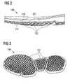
- Fig. 2
- shows a cross-sectional side view of another exemplary embodiment of a sole according to the invention;
- Fig. 3
- shows yet another exemplary embodiment of a sole according to the invention;
- Fig. 4
- shows a further exemplary embodiment of a sole according to the invention;
- Fig. 5
- shows a bottom view of an exemplary embodiment of a shoe according to the invention;
- Fig. 6
- depicts a part of a shoe according to an exemplary embodiment of the invention;
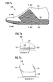
- Fig. 7a
- shows a schematic side view of an exemplary embodiment of a shoe according to the invention;
- Figs. 7b and 7c
- show schematic cross sectional views of the exemplary embodiment of
Fig. 7a ; - Fig. 7d
- shows a schematic bottom view of the exemplary embodiment of
Fig. 7a ; and - Figs. 8a, 8b and 8c
- illustrate a method of manufacturing a sole according to the invention.
- In the following, embodiments and variations of the present invention are described in more detail.
-
Figures 1a and 1b show an exemplary embodiment of a sole 100 for a shoe according to the present invention.Fig. 1a is a plan view of the sole 100 from below, i.e. from the ground engaging side, whereasFig. 1b is a plan view from above, i.e. from the side opposite the ground engaging side where the shoe upper (not shown infigures 1a and 1b ) would be located. - The sole 100 is generally configured to be used for a shoe, in particular a sports shoe such as a running or tennis shoe, but can be used for other kinds of sports such as basketball, soccer, cycling, volleyball, etc. as well. The sole 100 may be an outsole or a combination of an outsole and a midsole.
- The sole 100 comprises a
porous mesh 101. In the exemplary embodiment ofFig. 1 , the porous mesh is a textile mesh having a relatively coarse structure, i.e. the mesh openings are rather wide, having a diameter of roughly 1.4 mm. In general, the mesh openings can have a different diameter, such as 1.2 mm to 6 mm. In the specific embodiment shown inFig. 1 , themesh 101 is a textile made from polyester fibers. Other meshes could be used, e.g. a metal or fabric mesh. Themesh 101 is porous, i.e. the openings of themesh 101 are penetrable by or permeable to fluid or liquid substances or materials. More specifically, fluid or liquid substances or materials may penetrate the mesh from a first side of the mesh to reach a second side of the mesh opposite the first side. - The sole 100 also comprises a continuous
first layer 102 arranged at least partially on a first side of theporous mesh 101. Thefirst layer 102 may be made of rubber, but any other suitable material may be used. As shown inFig. 1b , the continuousfirst layer 102 is arranged at least partially on top of theporous mesh 101. Theporous mesh 101 is visible inFig. 1b for example in the heel portion of the sole 100, but need not be visible from above at all, i.e. thefirst layer 102 may completely cover theporous mesh 101 on the first side of theporous mesh 101. In general, thefirst layer 102 may be arranged on only a portion of theporous mesh 101. Conversely, there may be a portion of thefirst layer 102 being not arranged on theporous mesh 101. Thus, theporous mesh 101 and thefirst layer 102 may generally be in an overlapping configuration. - As shown in
Fig. 1a , thefirst layer 102 penetrates theporous mesh 101 at least partially to form atread structure 103 on a second side of the porous mesh opposite the first side. Thus, the material forming thetread structure 103 inFig. 1a is material of thefirst layer 102 which has penetrated theporous mesh 101 in the area where thetread structure 103 is formed. In other words, theporous mesh 101 is embedded in the first layer where the tread structure is formed. The material of thefirst layer 102 fills the mesh openings of theporous mesh 102 in the area of the tread structure at least partially. In this way, thefirst layer 102 and theporous mesh 101 are bonded at least in an area where thetread structure 103 is formed. - As can be seen in
Fig. 1a , the average size of the mesh openings formed by mesh fibers is smaller than the average size of the tread elements of thetread structure 103. In more detail, the diameter of a mesh opening is significantly smaller than the length of the elongated tread elements. - In general, the
tread structure 103 may have any suitable form to allow for good traction of the sole. Thus, inFig. 1a atread structure 103 is shown to have tread elements of an elongated shape, wherein each tread element has a zigzag arrangement and each tread element runs parallel to an adjacent tread element. However, the shape, size and arrangement of tread elements can generally be different. For example, the tread elements can be nub-shaped, star-shaped or the like. Also, tread elements may be separate from each other or may be connected. - Further, the shape, size and arrangement of the tread elements may vary across the sole. For example, the tread elements may be protruding to a greater extent in the areas of the sole with higher stress during use. Also, the tread elements may have a larger size in one area of the sole, e.g. in the heel portion, than in another area of the sole, e.g. in the toe portion.
- As depicted in
Fig. 1a , thetread elements 103 have gaps in between, and theporous mesh 101 is visible through the gaps. However, thetread structure 103 may also be arranged such that themesh 101 is not visible. - As depicted in
Fig. 1a , the sole 100 comprises asecond layer 104 arranged on the second side of theporous mesh 101. Thesecond layer 104 has a ring-like shape and comprises an aperture in which the tread structure is arranged. Thesecond layer 104 and thefirst layer 102 are bonded at least partially. In the example offigures 1a and 1b , thefirst layer 102 and thesecond layer 104 are both made from rubber. Thus, both layers form a tight and stable bond when being molded for example. It is to be noted that thesecond layer 104 is optional. - As shown in the cross-sectional view of
Fig. 2 , the sole 100 may also comprise a continuous third layer 201arranged on thefirst layer 102 comprising a different material than thefirst layer 102, for example ethylene vinyl acetate, EVA. Another example is polyurethane (PU) which is injected on top of thefirst layer 102. The third layer and thefirst layer 102 may be bonded at least partially. -
Fig. 3 shows another exemplary embodiment of a sole 100 according to the invention in which theporous mesh 101 extends throughout the entire sole 100. Themesh 101 extends from the toe portion of the sole 100 via the midfoot portion to the heel portion over the entire width of the sole 100. -
Fig. 4 shows a further exemplary embodiment of a sole 100 according to the present invention. As shown inFig. 4 , themesh 101 is folded in the midfoot portion of the sole 100, so that this foldedmesh 101 replaces or supplements, i.e. supports a tread element. In general, such folds may be arranged at different locations as well, for example in the forefoot or heel portion of the sole. Also, the number of folds of themesh 101 may vary. -
Fig. 5 shows a bottom view of ashoe 500 according to the invention. Theshoe 500 comprises a sole 100 as discussed above and an upper 501. The upper 501 is connected to the sole 100 for example via welding, sewing or gluing. -
Fig. 6 depicts part of ashoe 600 according to the invention comprising a sole 100 as described above and a part of a shoe upper 601 connected to the sole 100. Themesh 101 of the sole 100 extends into the shoe upper and forms the part of the shoe upper 601. The part of the shoe upper 601 formed by themesh 101 may be cut to a desired 2-dimensional shape and sewn or welded, for example while the shoe is lasted, to provide the shoe upper with the desired 3-dimensional shape. Other parts may be added to the shoe upper, e.g. a tongue, a heel and toe counter, a lacing system or similar components. -
Fig. 7a shows a side view of another exemplary embodiment of ashoe 500 according to the invention. In the example ofFig. 7a , themesh 101 extends into the upper 501 in the midfoot portion of theshoe 500 as can also be seen in the cross-sectional view ofFig. 7c . In contrast, themesh 101 does not extend into the upper 501 in the forefoot portion of theshoe 500 as shown in the cross-sectional view ofFig. 7b . Rather, as shown inFig. 7b , themesh 101 covers the sides of sole 100 and is folded over the upper edge of the sole 100 to be covered by the upper 501 in the border area of the sole 100.Fig. 7d shows a bottom view of theshoe 500 shown infigures 7a, 7b and 7c . - By means of
figures 8a ,8b and 8c an exemplary method of manufacturing a sole 100 as described above is described in the following. The exemplary method comprises an optional first step shown inFig. 8a in which asecond layer 104 is provided which will later be arranged on the second side of theporous mesh 101. As depicted inFig. 8a , thesecond layer 104 is placed in one half of amold cavity 801 having a tread structure 802 which will define thetread structure 103 of the final sole 100 and is in fact its negative. Thesecond layer 104 comprises an aperture in which thetread structure 103 of the final sole will be arranged. Thus, thesecond layer 104 in the exemplary method is ring-shaped and has a thickness of approximately 2 mm. In general, the second layer may have any size and shape. In the exemplary method, thesecond layer 104 is made from rubber, but may be made from any suitable material, and may also be made from a different material than thefirst layer 102. It is to be emphasized that providing thesecond layer 104 is an optional step. - As shown in
Fig. 8b , the exemplary method comprises the step of providing theporous mesh 101. In the exemplary method, themesh 101 is a textile and overlaps the ring-shapedsecond layer 104 by approximately 5 mm. Themesh 101 is put on thesecond layer 104 in the half of themold cavity 801. - As depicted in
Fig. 8c , the continuousfirst layer 102 is arranged at least partially on the first side of theporous mesh 101. In the exemplary method, thefirst layer 102 is an approximately 2mm thick rubber piece as large as the aperture of the underlyingsecond layer 104. In general, thefirst layer 102 may have any size and shape, and may be made from a different material than rubber. - Next, the other half of the mold cavity is arranged to close the mold cavity. Pressure and heat are applied to mold the
first layer 102, the optionalsecond layer 104 and theporous mesh 101 by compression molding, such that thefirst layer 102 penetrates theporous mesh 101 at least partially to form thetread structure 103 on the second side of theporous mesh 101 opposite the first side. Thereby, thefirst layer 102 and theporous mesh 101 are bonded at least in an area where thetread structure 103 is formed. - Optionally, after the material of the
first layer 102, e.g. rubber, has cured, athird layer 201 such as EVA can be applied on top of thefirst layer 102 in a mold. If themesh 101 is to extend into thethird layer 201, the material of thethird layer 201 may penetrate themesh 101 in this step. - In general, instead of compression molding, injection molding could be used as well. In this case, the
mesh 101 is arranged in a suitable mold and the material of thefirst layer 102 is injected through bores in the mold in liquid form to penetrate themesh 101 in the area of thetread structure 103. - Injection molding could also be used to apply a
third layer 201 such as an EVA or PU layer on top of thefirst layer 102. In this case, thefirst layer 102 and themesh 101 are molded first. After the material of thefirst layer 102, e.g. rubber, has cured, the material of thethird layer 201 such as EVA or PU is applied via injection molding on top of thefirst layer 102. If themesh 101 is to extend into thethird layer 201, the material of thethird layer 201 may penetrate themesh 101 in this step. - A method of manufacturing a shoe according to the invention comprises at least the steps of providing the sole 100 described above, and connecting a shoe upper to the sole 100. The method may further comprise the step of connecting the shoe upper to the sole 100 via the
mesh 101. -
- 100
- sole
- 101
- porous mesh
- 102
- first layer
- 103
- tread structure
- 104
- second layer
- 201
- third layer
- 500
- shoe
- 501
- shoe upper
- 600
- part of shoe
- 601
- part of shoe upper
- 801
- mold cavity
- 802
- tread structure in mold cavity
- In the following, further embodiments are described to facilitate the understanding of the invention:
- 1. Sole for a shoe, comprising:
- a. a porous mesh; and
- b. a continuous first layer arranged at least partially on a first side of the porous mesh, wherein
- 1. the first layer penetrates the porous mesh at least partially to form a tread structure on a second side of the porous mesh opposite the first side, and wherein
- 2. the first layer and the porous mesh are bonded at least in an area where the tread structure is formed.
- 2. Sole according to the preceding embodiment, further comprising a second layer arranged on the second side of the porous mesh, wherein the second layer comprises at least one aperture in which the tread structure is arranged at least partially, and wherein the second layer and the first layer are bonded at least partially.
- 3. Sole according to one of the preceding embodiments, further comprising a continuous third layer arranged on the first layer comprising a different material than the first layer, wherein the third layer and the first layer are bonded at least partially.
- 4. Sole according to one of the preceding embodiments, wherein the first layer is made of rubber.
- 5. Sole according to one of the preceding embodiments, wherein the mesh is made of metal or plastic or fabric.
- 6. Sole according to one of embodiments 2 to 5, wherein the second layer is made of rubber.
- 7. Sole according to one of the
embodiments 3 to 6, wherein the third layer is made of ethylene vinyl acetate, EVA, or polyurethane, PU. - 8. Sole according to one of the preceding embodiments, wherein the tread structure comprises tread elements.
- 9. Sole according to one of the preceding embodiments, wherein the average size of the mesh openings formed by mesh fibers are smaller than the average size of the tread elements.
- 10. Sole according to one of embodiments 8 to 9, wherein the tread elements have gaps in between and the porous mesh is visible through the gaps.
- 11. Sole according to one of the preceding embodiments, wherein the material of the first layer fills the mesh openings of the porous mesh in the area of the tread structure at least partially.
- 12. Sole according to one of the preceding embodiments, wherein the sole is configured to be used for a sports shoe.
- 13. Sole according to the preceding embodiment, wherein the sports shoe is a running or tennis shoe.
- 14. Shoe, comprising:
- a. a sole according to one of the preceding embodiments; and
- b. a shoe upper connected to the sole.
- 15. Shoe according to the preceding embodiment, wherein the mesh extends into the upper.
- 16. Shoe according to embodiment 15, wherein the mesh forms a part of the upper.
- 17. Method of manufacturing a sole according to one of embodiments 1 to 13, comprising the steps of:
- a. providing the porous mesh;
- b. arranging the continuous first layer at least partially on the first side of the porous mesh;
- c. molding the first layer and the porous mesh, such that the first layer penetrates the porous mesh at least partially to form the tread structure on the second side of the porous mesh opposite the first side, wherein the first layer and the porous mesh are bonded at least in an area where the tread structure is formed.
- 18. Method according to the preceding embodiment, wherein the step of molding comprises compression molding or injection molding.
- 19. Method according to one of embodiments 17 to 18, further comprising the steps of providing a second layer arranged on the second side of the porous mesh, wherein the second layer comprises at least one aperture in which the tread structure is arranged at least partially.
- 20. Method according to one of embodiments 17 to 19, further comprising the steps of
providing a continuous third layer arranged on the first layer comprising a different material than the first layer, and
bonding the third layer and the first layer at least partially. - 21. Method of manufacturing a shoe according to one of embodiments 14 to 16, comprising the steps of:
- a. providing the sole; and
- b. connecting the shoe upper to the sole.
- 22. Method according to the preceding embodiment, further comprising the step of connecting the shoe upper to the sole via the mesh.
Claims (15)
- Sole (100) for a shoe, comprising:a. a porous mesh (101); andb. a continuous first layer (102) arranged at least partially on a first side of the porous mesh (101), wherein1. the first layer (102) penetrates the porous mesh (101) at least partially to form a tread structure (103) on a second side of the porous mesh (101) opposite the first side, and wherein2. the first layer (102) and the porous mesh (101) are bonded at least in an area where the tread structure (103) is formed.
- Sole (100) according to the preceding claim, further comprising a second layer (104) arranged on the second side of the porous mesh (101), wherein the second layer (104) comprises at least one aperture in which the tread structure (103) is arranged at least partially, and wherein the second layer (104) and the first layer (102) are bonded at least partially.
- Sole (100) according to one of the preceding claims, further comprising a continuous third layer (201) arranged on the first layer (102) comprising a different material than the first layer (102), wherein the third layer (201) and the first layer (102) are bonded at least partially.
- Sole (100) according to one of the preceding claims, wherein the first layer (102) is made of rubber.
- Sole (100) according to one of claims 2 to 4, wherein the second layer (104) is made of rubber.
- Sole (100) according to one of the preceding claims, wherein the tread structure (103) comprises tread elements, and wherein the average size of the mesh openings formed by mesh fibers are smaller than the average size of the tread elements.
- Sole (100) according to one of the preceding claims, wherein the material of the first layer (102) fills the mesh openings of the porous mesh (101) in the area of the tread structure (103) at least partially.
- Shoe (500), comprising:a. a sole (100) according to one of the preceding claims; andb. a shoe upper (501) connected to the sole (100).
- Shoe (500) according to the preceding claim, wherein the mesh (101) extends into the upper (501).
- Shoe (500) according to claim 9, wherein the mesh (101) forms a part of the upper (501).
- Method of manufacturing a sole (100) according to one of claims 1 to 7, comprising the steps of:a. providing the porous mesh (101);b. arranging the continuous first layer (102) at least partially on the first side of the porous mesh (101);c. molding the first layer (102) and the porous mesh (101), such that the first layer (102) penetrates the porous mesh (101) at least partially to form the tread structure (103) on the second side of the porous mesh (101) opposite the first side, wherein the first layer (102) and the porous mesh (101) are bonded at least in an area where the tread structure (103) is formed.
- Method according to claim 11, further comprising the steps of providing a second layer (104) arranged on the second side of the porous mesh (101), wherein the second layer (104) comprises at least one aperture in which the tread structure (103) is arranged at least partially.
- Method according to one of claims 11 to 12, further comprising the steps of providing a continuous third layer (201) arranged on the first layer (102) comprising a different material than the first layer (102), and
bonding the third layer (201) and the first layer (102) at least partially. - Method of manufacturing a shoe (500) according to one of claims 8 to 10, comprising the steps of:a. providing the sole (100); andb. connecting the shoe upper (501) to the sole (100).
- Method according to the preceding claim, further comprising the step of connecting the shoe upper (501) to the sole (100) via the mesh (101).
Applications Claiming Priority (1)
| Application Number | Priority Date | Filing Date | Title |
|---|---|---|---|
| DE102014219918.2A DE102014219918B4 (en) | 2014-10-01 | 2014-10-01 | Sole for a shoe |
Publications (2)
| Publication Number | Publication Date |
|---|---|
| EP3001924A1 true EP3001924A1 (en) | 2016-04-06 |
| EP3001924B1 EP3001924B1 (en) | 2020-04-15 |
Family
ID=54207387
Family Applications (1)
| Application Number | Title | Priority Date | Filing Date |
|---|---|---|---|
| EP15187062.3A Active EP3001924B1 (en) | 2014-10-01 | 2015-09-28 | Sole for a shoe |
Country Status (4)
| Country | Link |
|---|---|
| US (1) | US10258104B2 (en) |
| EP (1) | EP3001924B1 (en) |
| CN (1) | CN105476174B (en) |
| DE (1) | DE102014219918B4 (en) |
Cited By (7)
| Publication number | Priority date | Publication date | Assignee | Title |
|---|---|---|---|---|
| ITUA20163865A1 (en) * | 2016-05-27 | 2017-11-27 | Jv Int S R L | SOLE FOR FOOTWEAR |
| WO2020033727A1 (en) * | 2018-08-08 | 2020-02-13 | Nike Innovate C.V. | Midsole structure of an article of footwear including mesh |
| EP3563710A4 (en) * | 2016-12-28 | 2020-07-29 | ASICS Corporation | Outsole and shoe |
| US10765172B2 (en) | 2014-07-30 | 2020-09-08 | NIKE, Imc. | Article of footwear with banking midsole with embedded resilient plate |
| US11730231B2 (en) | 2017-08-31 | 2023-08-22 | Nike, Inc. | Sole structure of an article of footwear and related methods |
| US11930884B2 (en) | 2020-03-29 | 2024-03-19 | Nike, Inc. | Sole structure of an article of footwear |
| US11937664B2 (en) | 2017-08-31 | 2024-03-26 | Nike, Inc. | Sole structure of an article of footwear and related methods |
Families Citing this family (78)
| Publication number | Priority date | Publication date | Assignee | Title |
|---|---|---|---|---|
| US9629415B2 (en) * | 2012-07-24 | 2017-04-25 | Nike, Inc. | Sole structure for an article of footwear |
| USD885718S1 (en) | 2015-05-19 | 2020-06-02 | Nike, Inc. | Shoe |
| USD809259S1 (en) * | 2016-08-15 | 2018-02-06 | Nike, Inc. | Shoe outsole |
| US20180160773A1 (en) * | 2016-12-08 | 2018-06-14 | Cels Enterprises, Inc. | Shoe outer sole with surface portions for flocking |
| USD852476S1 (en) | 2016-12-16 | 2019-07-02 | Puma SE | Shoe sole element |
| US10806209B2 (en) | 2017-01-06 | 2020-10-20 | Under Armour, Inc. | Composite soles |
| USD831939S1 (en) * | 2017-01-13 | 2018-10-30 | Dynasty Footwear, Ltd. | Shoe sole |
| USD954412S1 (en) * | 2017-12-01 | 2022-06-14 | Nike, Inc. | Shoe |
| USD923306S1 (en) | 2017-12-01 | 2021-06-29 | Nike, Inc. | Shoe |
| USD912964S1 (en) | 2018-01-29 | 2021-03-16 | Nike, Inc. | Shoe |
| USD874801S1 (en) | 2018-02-23 | 2020-02-11 | Puma SE | Shoe |
| USD877465S1 (en) * | 2018-02-23 | 2020-03-10 | Puma SE | Shoe |
| USD874098S1 (en) * | 2018-02-26 | 2020-02-04 | Puma SE | Shoe |
| USD874099S1 (en) * | 2018-02-27 | 2020-02-04 | Puma SE | Shoe |
| USD869833S1 (en) | 2018-03-09 | 2019-12-17 | Puma SE | Shoe sole |
| USD858051S1 (en) | 2018-04-04 | 2019-09-03 | Puma SE | Shoe |
| USD893144S1 (en) * | 2018-07-03 | 2020-08-18 | Tod's S.P.A. | Footwear sole |
| USD878022S1 (en) * | 2018-08-17 | 2020-03-17 | Nike, Inc. | Shoe |
| USD876059S1 (en) * | 2018-08-17 | 2020-02-25 | Nike, Inc. | Shoe |
| USD877472S1 (en) * | 2018-08-17 | 2020-03-10 | Nike, Inc. | Shoe |
| USD876058S1 (en) * | 2018-08-17 | 2020-02-25 | Nike, Inc. | Shoe |
| USD882222S1 (en) | 2018-08-23 | 2020-04-28 | Puma SE | Shoe |
| USD907903S1 (en) | 2018-08-23 | 2021-01-19 | Puma SE | Shoe |
| USD893855S1 (en) | 2018-08-24 | 2020-08-25 | Puma SE | Shoe |
| USD883620S1 (en) | 2018-08-24 | 2020-05-12 | Puma SE | Shoe |
| USD861303S1 (en) * | 2018-09-13 | 2019-10-01 | Nike, Inc. | Shoe |
| WO2020086792A1 (en) | 2018-10-25 | 2020-04-30 | University Of Florida Research Foundation, Incorporated | Gait modification apparatuses, systems and methods |
| US12096823B1 (en) * | 2018-11-30 | 2024-09-24 | Under Armour, Inc. | Article of footwear |
| USD894558S1 (en) * | 2019-01-07 | 2020-09-01 | Zhejiang Huanqiu Internet Of Things Technology Co., Ltd. | Footwear sole |
| USD889791S1 (en) * | 2019-01-10 | 2020-07-14 | Nike, Inc. | Shoe |
| USD889090S1 (en) * | 2019-01-10 | 2020-07-07 | Nike, Inc. | Shoe |
| USD866140S1 (en) * | 2019-01-10 | 2019-11-12 | Nike, Inc. | Shoe |
| USD891054S1 (en) | 2019-01-25 | 2020-07-28 | Puma SE | Shoe |
| USD891053S1 (en) | 2019-01-25 | 2020-07-28 | Puma SE | Shoe |
| USD885722S1 (en) | 2019-02-14 | 2020-06-02 | Puma SE | Shoe |
| USD893838S1 (en) | 2019-02-14 | 2020-08-25 | Puma SE | Shoe |
| USD890496S1 (en) | 2019-02-14 | 2020-07-21 | Puma SE | Shoe |
| USD875360S1 (en) | 2019-02-21 | 2020-02-18 | Puma SE | Shoe |
| USD890497S1 (en) | 2019-02-21 | 2020-07-21 | Puma SE | Shoe |
| USD889798S1 (en) | 2019-02-22 | 2020-07-14 | Puma SE | Shoe |
| USD890488S1 (en) | 2019-02-22 | 2020-07-21 | Puma SE | Shoe |
| JP1652801S (en) | 2019-05-14 | 2020-02-17 | ||
| USD919266S1 (en) * | 2019-08-20 | 2021-05-18 | Jiangsu Weite E-commerce Co., Ltd. | Sole |
| CN111820533B (en) * | 2020-06-30 | 2025-07-25 | 浙江中胤时尚股份有限公司 | Dynamic curved surface supporting sports shoes |
| USD957107S1 (en) * | 2020-10-12 | 2022-07-12 | Target Brands, Inc. | Footwear |
| USD950925S1 (en) * | 2020-10-12 | 2022-05-10 | Target Brands, Inc. | Footwear |
| CN112515287A (en) * | 2020-12-31 | 2021-03-19 | 际华三五一五皮革皮鞋有限公司 | Comfortable rubber outsole |
| USD988679S1 (en) * | 2021-03-05 | 2023-06-13 | Nike, Inc. | Shoe |
| USD988680S1 (en) * | 2021-03-19 | 2023-06-13 | Nike, Inc. | Shoe |
| USD947510S1 (en) * | 2021-04-08 | 2022-04-05 | Nike, Inc. | Shoe |
| USD948851S1 (en) * | 2021-04-16 | 2022-04-19 | Nike, Inc. | Shoe |
| USD948186S1 (en) * | 2021-06-09 | 2022-04-12 | Nike, Inc. | Shoe |
| USD951616S1 (en) * | 2021-06-09 | 2022-05-17 | Nike, Inc. | Shoe |
| USD1000072S1 (en) * | 2021-06-25 | 2023-10-03 | Nike, Inc. | Shoe |
| USD970182S1 (en) * | 2021-10-08 | 2022-11-22 | Nike, Inc. | Shoe |
| USD1028453S1 (en) * | 2021-12-06 | 2024-05-28 | Nike, Inc. | Shoe |
| USD972823S1 (en) * | 2021-12-17 | 2022-12-20 | Nike, Inc. | Shoe |
| USD1001448S1 (en) * | 2022-02-15 | 2023-10-17 | Nike, Inc. | Shoe |
| USD972270S1 (en) * | 2022-04-07 | 2022-12-13 | Nike, Inc. | Shoe |
| USD1033023S1 (en) * | 2022-06-24 | 2024-07-02 | Nike, Inc. | Shoe |
| USD990847S1 (en) * | 2022-09-30 | 2023-07-04 | Xuruihang (xiamen) Import and Export Co., LTD | Outsole |
| USD1050702S1 (en) * | 2023-02-10 | 2024-11-12 | Nike, Inc. | Shoe |
| USD1050701S1 (en) * | 2023-02-10 | 2024-11-12 | Nike, Inc. | Shoe |
| USD1010997S1 (en) * | 2023-06-14 | 2024-01-16 | Xiamen Hwish Import & Export Co., Ltd. | Shoe sole |
| USD1082262S1 (en) * | 2023-06-21 | 2025-07-08 | John Lobb (Société Par Actions Simplifiée) | Shoe sole |
| USD1087574S1 (en) * | 2023-06-23 | 2025-08-12 | Nike, Inc. | Shoe |
| USD1083338S1 (en) * | 2023-07-02 | 2025-07-15 | Lizzao Inc | Shoe sole |
| USD1043067S1 (en) * | 2023-07-11 | 2024-09-24 | Skechers U.S.A., Inc. Ii | Shoe outsole bottom |
| USD1046410S1 (en) * | 2023-11-17 | 2024-10-15 | Nike, Inc. | Shoe |
| USD1082250S1 (en) * | 2024-02-02 | 2025-07-08 | Nike, Inc. | Shoe |
| USD1089995S1 (en) * | 2024-03-15 | 2025-08-26 | Nike, Inc. | Shoe |
| US20250361727A1 (en) * | 2024-05-23 | 2025-11-27 | Macneil Ip Llc | Stair nosing |
| USD1121296S1 (en) * | 2024-07-31 | 2026-04-07 | Selkirk Sport, LLC | Footwear |
| USD1060981S1 (en) * | 2024-08-20 | 2025-02-11 | Quanzhou Moshidimen Trading Co., Ltd. | Sole |
| USD1119239S1 (en) * | 2024-10-04 | 2026-03-24 | Nike, Inc. | Shoe |
| USD1119241S1 (en) * | 2024-10-04 | 2026-03-24 | Nike, Inc. | Shoe |
| USD1119240S1 (en) * | 2024-10-04 | 2026-03-24 | Nike, Inc. | Shoe |
| DE102024133319A1 (en) * | 2024-11-14 | 2026-05-21 | Adidas Ag | LIQUID THERMOPLASTIC POLYMER APPLICATION SAMPLES FOR HIGH TRACTION APPLICATIONS |
Citations (8)
| Publication number | Priority date | Publication date | Assignee | Title |
|---|---|---|---|---|
| US2333303A (en) | 1941-05-16 | 1943-11-02 | Edward H Enos | Shoe having an impregnated fabric sole |
| US2364134A (en) | 1943-10-02 | 1944-12-05 | Bigelow Sanford Carpet Co Inc | Shoe sole |
| US2557946A (en) | 1948-02-18 | 1951-06-26 | Lloyd L Felker | Nonskid rubber sole construction |
| US5237758A (en) | 1992-04-07 | 1993-08-24 | Zachman Harry L | Safety shoe sole construction |
| US6032388A (en) | 1998-05-01 | 2000-03-07 | Puma Ag Rudolf Dassler Sport | Thin, flexible shoe outsole with injected-through tread elements, a method of producing such an outsole and a shoe provided with such an outsole |
| US6782642B2 (en) | 2000-08-02 | 2004-08-31 | Adidas International | Light running shoe |
| US20080216357A1 (en) * | 2007-03-06 | 2008-09-11 | Nike, Inc. | Article of Footwear with Mesh on Outsole and Insert |
| US20080263905A1 (en) * | 2007-04-29 | 2008-10-30 | Chin-Hsing Tai | Outsole with an embedded fabric layer |
Family Cites Families (15)
| Publication number | Priority date | Publication date | Assignee | Title |
|---|---|---|---|---|
| US354232A (en) * | 1886-12-14 | Sole for boots or shoes | ||
| US4494320A (en) * | 1982-11-18 | 1985-01-22 | 8-Track Shoe Corp. | Shoe outsole |
| ITPD20020246A1 (en) * | 2002-09-24 | 2004-03-25 | Geox Spa | STRUCTURE OF WATERPROOF AND BREATHABLE SOLE FOR FOOTWEAR AND FOOTWEAR MADE WITH THE SOLE. |
| US6237251B1 (en) * | 1991-08-21 | 2001-05-29 | Reebok International Ltd. | Athletic shoe construction |
| DE29601932U1 (en) * | 1996-02-08 | 1996-07-25 | Gore W L & Ass Gmbh | Breathable shoe sole |
| ITPD20040208A1 (en) * | 2004-07-30 | 2004-10-30 | Geox Spa | WATERPROOF AND BREATHABLE SOLE FOR FOOTWEAR |
| US7313876B2 (en) * | 2005-04-12 | 2008-01-01 | Wolverine World Wide, Inc. | Footwear outsole and method of manufacture |
| DK3001923T3 (en) * | 2006-03-03 | 2020-08-10 | Gore W L & Ass Gmbh | COMPOSITE SHOE SOLE, THERE CONSTRUCTED FOOTWEAR |
| ITPD20070107A1 (en) * | 2007-03-23 | 2008-09-24 | Frasson S R L | ANTI-SLIP TREADTRACK AND PROCEDURE FOR THE REALIZATION OF SUCH A TREAD |
| US20110192056A1 (en) * | 2010-02-05 | 2011-08-11 | Deckers Outdoor Corporation | Footwear including a self-adjusting midsole |
| FR2978019B1 (en) * | 2011-07-20 | 2014-08-15 | Salomon Sas | IMPROVED SHOE SHOE |
| US20130036633A1 (en) * | 2011-08-09 | 2013-02-14 | Ching-Nan LEE | Non-slip sole structure |
| CN202385848U (en) * | 2011-11-09 | 2012-08-22 | 石狮蚂蚁城鞋服有限公司 | Omnidirectional balance damping anti-skid shoes |
| US9241535B2 (en) * | 2013-03-14 | 2016-01-26 | Nike, Inc. | Sole structures and articles incorporating same |
| US9516917B2 (en) * | 2014-01-16 | 2016-12-13 | Nike, Inc. | Sole system having protruding members |
-
2014
- 2014-10-01 DE DE102014219918.2A patent/DE102014219918B4/en active Active
-
2015
- 2015-09-25 CN CN201510621668.2A patent/CN105476174B/en active Active
- 2015-09-28 EP EP15187062.3A patent/EP3001924B1/en active Active
- 2015-10-01 US US14/872,723 patent/US10258104B2/en active Active
Patent Citations (8)
| Publication number | Priority date | Publication date | Assignee | Title |
|---|---|---|---|---|
| US2333303A (en) | 1941-05-16 | 1943-11-02 | Edward H Enos | Shoe having an impregnated fabric sole |
| US2364134A (en) | 1943-10-02 | 1944-12-05 | Bigelow Sanford Carpet Co Inc | Shoe sole |
| US2557946A (en) | 1948-02-18 | 1951-06-26 | Lloyd L Felker | Nonskid rubber sole construction |
| US5237758A (en) | 1992-04-07 | 1993-08-24 | Zachman Harry L | Safety shoe sole construction |
| US6032388A (en) | 1998-05-01 | 2000-03-07 | Puma Ag Rudolf Dassler Sport | Thin, flexible shoe outsole with injected-through tread elements, a method of producing such an outsole and a shoe provided with such an outsole |
| US6782642B2 (en) | 2000-08-02 | 2004-08-31 | Adidas International | Light running shoe |
| US20080216357A1 (en) * | 2007-03-06 | 2008-09-11 | Nike, Inc. | Article of Footwear with Mesh on Outsole and Insert |
| US20080263905A1 (en) * | 2007-04-29 | 2008-10-30 | Chin-Hsing Tai | Outsole with an embedded fabric layer |
Cited By (15)
| Publication number | Priority date | Publication date | Assignee | Title |
|---|---|---|---|---|
| US12064009B2 (en) | 2014-07-30 | 2024-08-20 | Nike, Inc. | Article of footwear with banking midsole with embedded resilient plate |
| US10765172B2 (en) | 2014-07-30 | 2020-09-08 | NIKE, Imc. | Article of footwear with banking midsole with embedded resilient plate |
| ITUA20163865A1 (en) * | 2016-05-27 | 2017-11-27 | Jv Int S R L | SOLE FOR FOOTWEAR |
| EP3248494A1 (en) * | 2016-05-27 | 2017-11-29 | JV International S.r.l. | Footwear sole |
| EP3563710A4 (en) * | 2016-12-28 | 2020-07-29 | ASICS Corporation | Outsole and shoe |
| US11395523B2 (en) | 2016-12-28 | 2022-07-26 | Asics Corporation | Outsole and shoe |
| US11730231B2 (en) | 2017-08-31 | 2023-08-22 | Nike, Inc. | Sole structure of an article of footwear and related methods |
| US11937664B2 (en) | 2017-08-31 | 2024-03-26 | Nike, Inc. | Sole structure of an article of footwear and related methods |
| US12383023B2 (en) | 2017-08-31 | 2025-08-12 | Nike, Inc. | Sole structure of an article of footwear and related methods |
| US12426671B2 (en) | 2017-08-31 | 2025-09-30 | Nike, Inc. | Sole structure of an article of footwear and related methods |
| US11930882B2 (en) | 2018-08-08 | 2024-03-19 | Nike, Inc. | Midsole structure of an article of footwear including mesh |
| WO2020033727A1 (en) * | 2018-08-08 | 2020-02-13 | Nike Innovate C.V. | Midsole structure of an article of footwear including mesh |
| EP4470409A3 (en) * | 2018-08-08 | 2025-01-22 | Nike Innovate C.V. | Sole structure of an article of footwear including mesh |
| US12426670B2 (en) | 2018-08-08 | 2025-09-30 | Nike, Inc. | Midsole structure of an article of footwear including mesh |
| US11930884B2 (en) | 2020-03-29 | 2024-03-19 | Nike, Inc. | Sole structure of an article of footwear |
Also Published As
| Publication number | Publication date |
|---|---|
| US20160095384A1 (en) | 2016-04-07 |
| DE102014219918A1 (en) | 2016-04-07 |
| US10258104B2 (en) | 2019-04-16 |
| DE102014219918B4 (en) | 2016-12-29 |
| EP3001924B1 (en) | 2020-04-15 |
| CN105476174A (en) | 2016-04-13 |
| CN105476174B (en) | 2020-04-07 |
Similar Documents
| Publication | Publication Date | Title |
|---|---|---|
| EP3001924B1 (en) | Sole for a shoe | |
| US12220019B2 (en) | Footwear with a composite plate sole assembly | |
| US10893720B2 (en) | Footwear having sensory feedback outsole | |
| EP1773149B1 (en) | Cleated article of footwear and method of manufacture | |
| CN110074510B (en) | Contoured fluid-filled chamber | |
| JP6730282B2 (en) | Braided article with internal midsole structure | |
| EP3081110B1 (en) | Sole assembly for an article of footwear | |
| US9839255B2 (en) | Sole structure for article of footwear | |
| CN107048585B (en) | Sole structure and article of footwear with lightweight midsole with segmented protection | |
| EP3003699B1 (en) | Article of footwear and method for forming the article | |
| US20170135441A1 (en) | Multi-component sole structure having an auxetic configuration | |
| EP2798969A1 (en) | Sole for a shoe | |
| EP3386335A1 (en) | Article having sole assembly with cleats | |
| CN111602926B (en) | Multi-component sole structure with auxetic structure | |
| US11617422B2 (en) | Cleat structure for article of footwear | |
| CN113925256A (en) | Shoe with net sole structure | |
| HK40058746A (en) | Footwear with mesh sole construction | |
| HK40012210B (en) | Contoured fluid-filled chamber | |
| HK40012210A (en) | Contoured fluid-filled chamber | |
| HK1222518A1 (en) | Auxetic structures and footwear with soles having auxetic structures |
Legal Events
| Date | Code | Title | Description |
|---|---|---|---|
| PUAI | Public reference made under article 153(3) epc to a published international application that has entered the european phase |
Free format text: ORIGINAL CODE: 0009012 |
|
| AK | Designated contracting states |
Kind code of ref document: A1 Designated state(s): AL AT BE BG CH CY CZ DE DK EE ES FI FR GB GR HR HU IE IS IT LI LT LU LV MC MK MT NL NO PL PT RO RS SE SI SK SM TR |
|
| AX | Request for extension of the european patent |
Extension state: BA ME |
|
| 17P | Request for examination filed |
Effective date: 20161006 |
|
| RBV | Designated contracting states (corrected) |
Designated state(s): AL AT BE BG CH CY CZ DE DK EE ES FI FR GB GR HR HU IE IS IT LI LT LU LV MC MK MT NL NO PL PT RO RS SE SI SK SM TR |
|
| STAA | Information on the status of an ep patent application or granted ep patent |
Free format text: STATUS: EXAMINATION IS IN PROGRESS |
|
| 17Q | First examination report despatched |
Effective date: 20181113 |
|
| GRAP | Despatch of communication of intention to grant a patent |
Free format text: ORIGINAL CODE: EPIDOSNIGR1 |
|
| STAA | Information on the status of an ep patent application or granted ep patent |
Free format text: STATUS: GRANT OF PATENT IS INTENDED |
|
| INTG | Intention to grant announced |
Effective date: 20191016 |
|
| GRAS | Grant fee paid |
Free format text: ORIGINAL CODE: EPIDOSNIGR3 |
|
| GRAA | (expected) grant |
Free format text: ORIGINAL CODE: 0009210 |
|
| STAA | Information on the status of an ep patent application or granted ep patent |
Free format text: STATUS: THE PATENT HAS BEEN GRANTED |
|
| AK | Designated contracting states |
Kind code of ref document: B1 Designated state(s): AL AT BE BG CH CY CZ DE DK EE ES FI FR GB GR HR HU IE IS IT LI LT LU LV MC MK MT NL NO PL PT RO RS SE SI SK SM TR |
|
| REG | Reference to a national code |
Ref country code: CH Ref legal event code: EP |
|
| REG | Reference to a national code |
Ref country code: DE Ref legal event code: R096 Ref document number: 602015050631 Country of ref document: DE |
|
| REG | Reference to a national code |
Ref country code: IE Ref legal event code: FG4D |
|
| REG | Reference to a national code |
Ref country code: AT Ref legal event code: REF Ref document number: 1256269 Country of ref document: AT Kind code of ref document: T Effective date: 20200515 |
|
| REG | Reference to a national code |
Ref country code: NL Ref legal event code: MP Effective date: 20200415 |
|
| REG | Reference to a national code |
Ref country code: LT Ref legal event code: MG4D |
|
| PG25 | Lapsed in a contracting state [announced via postgrant information from national office to epo] |
Ref country code: NO Free format text: LAPSE BECAUSE OF FAILURE TO SUBMIT A TRANSLATION OF THE DESCRIPTION OR TO PAY THE FEE WITHIN THE PRESCRIBED TIME-LIMIT Effective date: 20200715 Ref country code: FI Free format text: LAPSE BECAUSE OF FAILURE TO SUBMIT A TRANSLATION OF THE DESCRIPTION OR TO PAY THE FEE WITHIN THE PRESCRIBED TIME-LIMIT Effective date: 20200415 Ref country code: IS Free format text: LAPSE BECAUSE OF FAILURE TO SUBMIT A TRANSLATION OF THE DESCRIPTION OR TO PAY THE FEE WITHIN THE PRESCRIBED TIME-LIMIT Effective date: 20200815 Ref country code: LT Free format text: LAPSE BECAUSE OF FAILURE TO SUBMIT A TRANSLATION OF THE DESCRIPTION OR TO PAY THE FEE WITHIN THE PRESCRIBED TIME-LIMIT Effective date: 20200415 Ref country code: GR Free format text: LAPSE BECAUSE OF FAILURE TO SUBMIT A TRANSLATION OF THE DESCRIPTION OR TO PAY THE FEE WITHIN THE PRESCRIBED TIME-LIMIT Effective date: 20200716 Ref country code: SE Free format text: LAPSE BECAUSE OF FAILURE TO SUBMIT A TRANSLATION OF THE DESCRIPTION OR TO PAY THE FEE WITHIN THE PRESCRIBED TIME-LIMIT Effective date: 20200415 Ref country code: NL Free format text: LAPSE BECAUSE OF FAILURE TO SUBMIT A TRANSLATION OF THE DESCRIPTION OR TO PAY THE FEE WITHIN THE PRESCRIBED TIME-LIMIT Effective date: 20200415 Ref country code: PT Free format text: LAPSE BECAUSE OF FAILURE TO SUBMIT A TRANSLATION OF THE DESCRIPTION OR TO PAY THE FEE WITHIN THE PRESCRIBED TIME-LIMIT Effective date: 20200817 |
|
| REG | Reference to a national code |
Ref country code: AT Ref legal event code: MK05 Ref document number: 1256269 Country of ref document: AT Kind code of ref document: T Effective date: 20200415 |
|
| PG25 | Lapsed in a contracting state [announced via postgrant information from national office to epo] |
Ref country code: BG Free format text: LAPSE BECAUSE OF FAILURE TO SUBMIT A TRANSLATION OF THE DESCRIPTION OR TO PAY THE FEE WITHIN THE PRESCRIBED TIME-LIMIT Effective date: 20200715 Ref country code: HR Free format text: LAPSE BECAUSE OF FAILURE TO SUBMIT A TRANSLATION OF THE DESCRIPTION OR TO PAY THE FEE WITHIN THE PRESCRIBED TIME-LIMIT Effective date: 20200415 Ref country code: LV Free format text: LAPSE BECAUSE OF FAILURE TO SUBMIT A TRANSLATION OF THE DESCRIPTION OR TO PAY THE FEE WITHIN THE PRESCRIBED TIME-LIMIT Effective date: 20200415 Ref country code: RS Free format text: LAPSE BECAUSE OF FAILURE TO SUBMIT A TRANSLATION OF THE DESCRIPTION OR TO PAY THE FEE WITHIN THE PRESCRIBED TIME-LIMIT Effective date: 20200415 |
|
| PG25 | Lapsed in a contracting state [announced via postgrant information from national office to epo] |
Ref country code: AL Free format text: LAPSE BECAUSE OF FAILURE TO SUBMIT A TRANSLATION OF THE DESCRIPTION OR TO PAY THE FEE WITHIN THE PRESCRIBED TIME-LIMIT Effective date: 20200415 |
|
| REG | Reference to a national code |
Ref country code: DE Ref legal event code: R097 Ref document number: 602015050631 Country of ref document: DE |
|
| PG25 | Lapsed in a contracting state [announced via postgrant information from national office to epo] |
Ref country code: DK Free format text: LAPSE BECAUSE OF FAILURE TO SUBMIT A TRANSLATION OF THE DESCRIPTION OR TO PAY THE FEE WITHIN THE PRESCRIBED TIME-LIMIT Effective date: 20200415 Ref country code: ES Free format text: LAPSE BECAUSE OF FAILURE TO SUBMIT A TRANSLATION OF THE DESCRIPTION OR TO PAY THE FEE WITHIN THE PRESCRIBED TIME-LIMIT Effective date: 20200415 Ref country code: RO Free format text: LAPSE BECAUSE OF FAILURE TO SUBMIT A TRANSLATION OF THE DESCRIPTION OR TO PAY THE FEE WITHIN THE PRESCRIBED TIME-LIMIT Effective date: 20200415 Ref country code: IT Free format text: LAPSE BECAUSE OF FAILURE TO SUBMIT A TRANSLATION OF THE DESCRIPTION OR TO PAY THE FEE WITHIN THE PRESCRIBED TIME-LIMIT Effective date: 20200415 Ref country code: CZ Free format text: LAPSE BECAUSE OF FAILURE TO SUBMIT A TRANSLATION OF THE DESCRIPTION OR TO PAY THE FEE WITHIN THE PRESCRIBED TIME-LIMIT Effective date: 20200415 Ref country code: SM Free format text: LAPSE BECAUSE OF FAILURE TO SUBMIT A TRANSLATION OF THE DESCRIPTION OR TO PAY THE FEE WITHIN THE PRESCRIBED TIME-LIMIT Effective date: 20200415 Ref country code: EE Free format text: LAPSE BECAUSE OF FAILURE TO SUBMIT A TRANSLATION OF THE DESCRIPTION OR TO PAY THE FEE WITHIN THE PRESCRIBED TIME-LIMIT Effective date: 20200415 Ref country code: AT Free format text: LAPSE BECAUSE OF FAILURE TO SUBMIT A TRANSLATION OF THE DESCRIPTION OR TO PAY THE FEE WITHIN THE PRESCRIBED TIME-LIMIT Effective date: 20200415 |
|
| PLBE | No opposition filed within time limit |
Free format text: ORIGINAL CODE: 0009261 |
|
| STAA | Information on the status of an ep patent application or granted ep patent |
Free format text: STATUS: NO OPPOSITION FILED WITHIN TIME LIMIT |
|
| PG25 | Lapsed in a contracting state [announced via postgrant information from national office to epo] |
Ref country code: PL Free format text: LAPSE BECAUSE OF FAILURE TO SUBMIT A TRANSLATION OF THE DESCRIPTION OR TO PAY THE FEE WITHIN THE PRESCRIBED TIME-LIMIT Effective date: 20200415 Ref country code: SK Free format text: LAPSE BECAUSE OF FAILURE TO SUBMIT A TRANSLATION OF THE DESCRIPTION OR TO PAY THE FEE WITHIN THE PRESCRIBED TIME-LIMIT Effective date: 20200415 |
|
| 26N | No opposition filed |
Effective date: 20210118 |
|
| PG25 | Lapsed in a contracting state [announced via postgrant information from national office to epo] |
Ref country code: MC Free format text: LAPSE BECAUSE OF FAILURE TO SUBMIT A TRANSLATION OF THE DESCRIPTION OR TO PAY THE FEE WITHIN THE PRESCRIBED TIME-LIMIT Effective date: 20200415 |
|
| REG | Reference to a national code |
Ref country code: CH Ref legal event code: PL |
|
| PG25 | Lapsed in a contracting state [announced via postgrant information from national office to epo] |
Ref country code: SI Free format text: LAPSE BECAUSE OF FAILURE TO SUBMIT A TRANSLATION OF THE DESCRIPTION OR TO PAY THE FEE WITHIN THE PRESCRIBED TIME-LIMIT Effective date: 20200415 |
|
| REG | Reference to a national code |
Ref country code: BE Ref legal event code: MM Effective date: 20200930 |
|
| PG25 | Lapsed in a contracting state [announced via postgrant information from national office to epo] |
Ref country code: LU Free format text: LAPSE BECAUSE OF NON-PAYMENT OF DUE FEES Effective date: 20200928 |
|
| PG25 | Lapsed in a contracting state [announced via postgrant information from national office to epo] |
Ref country code: BE Free format text: LAPSE BECAUSE OF NON-PAYMENT OF DUE FEES Effective date: 20200930 Ref country code: CH Free format text: LAPSE BECAUSE OF NON-PAYMENT OF DUE FEES Effective date: 20200930 Ref country code: LI Free format text: LAPSE BECAUSE OF NON-PAYMENT OF DUE FEES Effective date: 20200930 Ref country code: IE Free format text: LAPSE BECAUSE OF NON-PAYMENT OF DUE FEES Effective date: 20200928 |
|
| PG25 | Lapsed in a contracting state [announced via postgrant information from national office to epo] |
Ref country code: TR Free format text: LAPSE BECAUSE OF FAILURE TO SUBMIT A TRANSLATION OF THE DESCRIPTION OR TO PAY THE FEE WITHIN THE PRESCRIBED TIME-LIMIT Effective date: 20200415 Ref country code: MT Free format text: LAPSE BECAUSE OF FAILURE TO SUBMIT A TRANSLATION OF THE DESCRIPTION OR TO PAY THE FEE WITHIN THE PRESCRIBED TIME-LIMIT Effective date: 20200415 Ref country code: CY Free format text: LAPSE BECAUSE OF FAILURE TO SUBMIT A TRANSLATION OF THE DESCRIPTION OR TO PAY THE FEE WITHIN THE PRESCRIBED TIME-LIMIT Effective date: 20200415 |
|
| PG25 | Lapsed in a contracting state [announced via postgrant information from national office to epo] |
Ref country code: MK Free format text: LAPSE BECAUSE OF FAILURE TO SUBMIT A TRANSLATION OF THE DESCRIPTION OR TO PAY THE FEE WITHIN THE PRESCRIBED TIME-LIMIT Effective date: 20200415 |
|
| P01 | Opt-out of the competence of the unified patent court (upc) registered |
Effective date: 20230523 |
|
| PGFP | Annual fee paid to national office [announced via postgrant information from national office to epo] |
Ref country code: FR Payment date: 20240820 Year of fee payment: 10 |
|
| PGFP | Annual fee paid to national office [announced via postgrant information from national office to epo] |
Ref country code: DE Payment date: 20250820 Year of fee payment: 11 |
|
| PGFP | Annual fee paid to national office [announced via postgrant information from national office to epo] |
Ref country code: GB Payment date: 20250827 Year of fee payment: 11 |