EP3001697A1 - Sound capture system - Google Patents
Sound capture system Download PDFInfo
- Publication number
- EP3001697A1 EP3001697A1 EP14186544.4A EP14186544A EP3001697A1 EP 3001697 A1 EP3001697 A1 EP 3001697A1 EP 14186544 A EP14186544 A EP 14186544A EP 3001697 A1 EP3001697 A1 EP 3001697A1
- Authority
- EP
- European Patent Office
- Prior art keywords
- microphones
- omnidirectional
- output signals
- microphone
- capture system
- Prior art date
- Legal status (The legal status is an assumption and is not a legal conclusion. Google has not performed a legal analysis and makes no representation as to the accuracy of the status listed.)
- Granted
Links
Images



Classifications
-
- H—ELECTRICITY
- H04—ELECTRIC COMMUNICATION TECHNIQUE
- H04R—LOUDSPEAKERS, MICROPHONES, GRAMOPHONE PICK-UPS OR LIKE ACOUSTIC ELECTROMECHANICAL TRANSDUCERS; ELECTRIC HEARING AIDS; PUBLIC ADDRESS SYSTEMS
- H04R3/00—Circuits for transducers
- H04R3/005—Circuits for transducers for combining the signals of two or more microphones
-
- H—ELECTRICITY
- H04—ELECTRIC COMMUNICATION TECHNIQUE
- H04R—LOUDSPEAKERS, MICROPHONES, GRAMOPHONE PICK-UPS OR LIKE ACOUSTIC ELECTROMECHANICAL TRANSDUCERS; ELECTRIC HEARING AIDS; PUBLIC ADDRESS SYSTEMS
- H04R1/00—Details of transducers, loudspeakers or microphones
- H04R1/20—Arrangements for obtaining desired frequency or directional characteristics
- H04R1/32—Arrangements for obtaining desired frequency or directional characteristics for obtaining desired directional characteristic only
- H04R1/40—Arrangements for obtaining desired frequency or directional characteristics for obtaining desired directional characteristic only by combining a number of identical transducers
- H04R1/406—Arrangements for obtaining desired frequency or directional characteristics for obtaining desired directional characteristic only by combining a number of identical transducers microphones
-
- H—ELECTRICITY
- H04—ELECTRIC COMMUNICATION TECHNIQUE
- H04R—LOUDSPEAKERS, MICROPHONES, GRAMOPHONE PICK-UPS OR LIKE ACOUSTIC ELECTROMECHANICAL TRANSDUCERS; ELECTRIC HEARING AIDS; PUBLIC ADDRESS SYSTEMS
- H04R2201/00—Details of transducers, loudspeakers or microphones covered by H04R1/00 but not provided for in any of its subgroups
- H04R2201/40—Details of arrangements for obtaining desired directional characteristic by combining a number of identical transducers covered by H04R1/40 but not provided for in any of its subgroups
- H04R2201/401—2D or 3D arrays of transducers
-
- H—ELECTRICITY
- H04—ELECTRIC COMMUNICATION TECHNIQUE
- H04R—LOUDSPEAKERS, MICROPHONES, GRAMOPHONE PICK-UPS OR LIKE ACOUSTIC ELECTROMECHANICAL TRANSDUCERS; ELECTRIC HEARING AIDS; PUBLIC ADDRESS SYSTEMS
- H04R2430/00—Signal processing covered by H04R, not provided for in its groups
- H04R2430/20—Processing of the output signals of the acoustic transducers of an array for obtaining a desired directivity characteristic
-
- H—ELECTRICITY
- H04—ELECTRIC COMMUNICATION TECHNIQUE
- H04S—STEREOPHONIC SYSTEMS
- H04S2400/00—Details of stereophonic systems covered by H04S but not provided for in its groups
- H04S2400/15—Aspects of sound capture and related signal processing for recording or reproduction
Definitions
- the disclosure relates to a sound capture system, in particular to a sound capture system with a spherical microphone array for use in a modal beamforming system.
- a microphone array-based modal beamforming system commonly comprises a spherical microphone array of a multiplicity of microphones equally distributed over the surface of a solid or virtual sphere for converting sounds into electrical audio signals and a modal beamformer combining the audio signals generated by the microphones to form an auditory scene representative of at least a portion of an acoustic sound field.
- This combination enables picking up acoustic signals dependent on their direction of propagation.
- microphone arrays are also sometimes referred to as spatial filters.
- Spherical microphone arrays exhibit low- and high-frequency limitations, so that the soundfield can only be accurately described over a limited frequency range.
- the sphere may exist physically, or may merely be conceptual.
- the microphones are arranged around a rigid sphere (e.g., made of wood, hard plastic or the like).
- the microphones are arranged in free-field around an "open" sphere, referred to as an open-sphere configuration.
- the rigid-sphere configuration provides a more robust numerical formulation, the open-sphere configuration might be more desirable for use at low frequencies, where large spheres are realized.
- directional microphones i.e., microphones having an axis along which they exhibit maximum sensitivity
- directional microphones are commonly much bulkier than omnidirectional microphones, i.e., microphones having sensitivity independent of the direction.
- An exemplary type of directional microphone is called a shotgun microphone, which is also known as a line plus gradient microphone. Shotgun microphones may comprise an acoustic tube that, with its mechanical structure, reduces noises that arrive from directions other than directly in front of the microphone along the axis of the tube.
- Another exemplary directional microphone is a parabolic dish that concentrates the acoustic signal from one direction by reflecting away other noise sources coming from directions other than the desired direction.
- a sound capture system that avoids the dimensional problems noted above is desired.
- a sound capture system may include a first number of first omnidirectional microphones that provide first output signals with an omnidirectional response pattern and that are disposed at different positions in a first equidistance from a point of symmetry.
- the sound capture system may further include a second number of second omnidirectional microphones that provide second output signals with an omnidirectional response pattern and that are disposed at different positions in a second equidistance from the point of symmetry, and an evaluation circuit that is configured to receive the first output signals and the second output signals, and to superimpose the first and second output signals of pairs of omnidirectional microphones for producing, in response thereto, third output signals with an directional response pattern.
- the second number is a multiple of two and the first equidistance is smaller than the second equidistance.
- Each of the second omnidirectional microphones forms with another of the second omnidirectional microphones a pair of second microphones, the microphones of a pair of second microphones being disposed in line with each other and the point of symmetry.
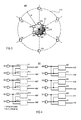
- FIG. 1 is a schematic diagram of an array 100 of microphones.
- Microphones 103-108 are disposed at different positions in a first equidistance d1 from a point of symmetry 101.
- Microphones 109-114 are disposed at different positions in a second equidistance d2 from the point of symmetry 101.
- First microphones 103-108 are arranged on an open sphere 115 in a basic hexahedron structure, and second microphones 109-114 are arranged on an open sphere 116 also in a basic hexahedron structure.
- the difference between the first equidistance d1 and the point of symmetry 101 may be between 0.5cm and 1.5cm, e.g., 0.85cm.
- the difference between the second equidistance d2 and the first equidistance d1 may be between 9cm and 11cm, e.g., 10cm.
- the difference between the first equidistance d1 and the point of symmetry 101 is smaller than the difference between the second equidistance d2 and the first equidistance d1.
- a center omnidirectional microphone 102 provides a fourth output signal with an omnidirectional response and is disposed at the point of symmetry 101.
- an evaluation circuit 200 for array 100 receives the first output signals from the first microphones 103-108 and the second output signals from the second microphones 109-114, and superimposes by way of signal couplers 220-225 the output signals of pairs of the second omnidirectional microphones for producing, in response thereto, six third output signals 207-212 with a directional response pattern.
- Each of the second omnidirectional microphones109-114 forms a pair of second microphones with another second omnidirectional microphone that is disposed in line with it and the point of symmetry.
- Signals with a directional response pattern are signals provided by a directional (e.g., unidirectional) microphone constellation and signals with an omnidirectional response pattern are signals provided by an omnidirectional microphone constellation.
- Evaluation circuit 200 may further receive the fourth output signal from the center microphone 102 and superimpose by way of signal couplers 214-219 the output signal of each first microphones 103-108 with the fourth output signal from the center microphone 102 for producing, in response thereto, six fifth output signals 201-206 with a directional response pattern.
- the center microphone 102 may be used, in a similar way as done above in connection with the inner ring microphones 102-108, also for the outer ring microphones 109-114, for the combination/formation of the desired virtual directional microphones.
- a combination (difference) between the outer ring microphones 109-114 with the inner ring microphones 102-108 is possible, for example, microphone 109 may be combined with microphone 103 and so on. Following this concept leads to a maximum logical combination of six different distances and hence 26 optimal frequency ranges which could further be beneficially combined.
- FIG. 3 is a schematic diagram of an array 300 of microphones.
- First microphones 303-308 are disposed at different positions in a first equidistance d3 from a point of symmetry 301.
- Microphones 309-314 are disposed at different positions in a second equidistance d4 from the point of symmetry 301.
- first microphones 303-308 may be arranged on an open sphere or a rigid sphere 315 in a basic hexahedron structure, and second microphones 309-314 are arranged on an open sphere 316 also in a basic hexahedron structure.
- the diameter of the inner (rigid) sphere 315 may be 1.5cm or more so that the difference between the first equidistance d3 and the point of symmetry 101 may be greater than 0.75cm.
- the difference between the second equidistance d4 and the point of symmetry 101 may be between 9 and 11cm for example.
- the difference between the first equidistance d1 and the point of symmetry 101 is smaller than the difference between the second equidistance d2 and the first equidistance d1.
- No center omnidirectional microphone is required here in contrast to the sound capture system illustrated above in connection with Figures 1 and 2 .
- an evaluation circuit 400 for array 300 with open sphere receives the first output signals from first microphones 303-308 and the second output signals from second microphones 309-314, and superimposes by way of signal couplers 414-419 the first output signals from pairs of omnidirectional microphones for producing, in response thereto, six fifth output signals 401-406 with a directional response pattern.
- Each of the second omnidirectional microphones 309-314 forms a pair of second microphones with another second omnidirectional microphone that is disposed in line with it and the point of symmetry.
- Evaluation circuit 400 may further superimpose by way of signal couplers 420-425 the second output signals from pairs of second omnidirectional microphones for producing, in response thereto, six third output signals 407-412 with a directional response pattern.
- Each of the second omnidirectional microphones 309-314 forms a pair of second microphones with another second omnidirectional microphone that is disposed in line with it and the point of symmetry.
- Microphones mounted on a solid sphere do not have to be directional and hence it is not necessary to use directional microphones on the inner (rigid) sphere 315.
- the way described above to form virtual directional microphones from omnidirectional microphones disposed on an open sphere does not work with a solid body residing at a central line on opposite sides of a solid body, i.e., a rigid sphere. This means that when using a rigid sphere 315 signal couplers 414-419 in the system shown in Figure 4 can be omitted without substitution and instead microphones 303-308 directly provide signals 401-406.
- the rigid sphere 315 Since with the rigid sphere 315 an obstacle resides in-between two opposite microphones on the outer sphere, e.g., microphone 309 and 312, which may require combining microphone 309 with microphone 303 instead of microphone 312. Otherwise, due to the fact that the outer sphere is only used to cover the low spectral range of a modal beamformer, the diffraction of a small obstacle in the spectral range with larger wave lengths than the dimensions of the obstacle, i.e., the solid center sphere, may play a minor role in practice.
- FIG. 5 is a schematic illustration of a 6-element 3D microphone array 500, which is applicable instead of sphere 315 in the array shown in Figure 3 , and which is mounted in a sound-diffracting structure provided by rigid sphere 501. Note that only three of the six microphone elements can be seen in Figure 5 (i.e., microphones 502, 503, and 504), while the remaining three microphone elements are hidden on the back side of the sphere 500. All six microphone elements are mounted on the surface of sphere 500 at points where an included regular octahedron's vertices would contact the spherical surface. Other shapes (structures) such as a hexahedron shape may be used as well. The individual microphones are omnidirectional microphones.
- Figure 6 shows a perspective view of a 3D microphone array 600 having a hexahedron shape.
- microphone array 600 of Figure 6 has a plurality of individual omnidirectional microphones, analogous to First microphones 303-308 in the array shown in Figure 3 , distributed around and integrated into different rigid, triangular sections 601 of sphere 600, where the microphones elements are mounted onto the surface of each square section 601.
- the microphones may be distributed uniformly or non-uniformly around the polyhedron, with each square section 601 having the same number of microphone elements or different square sections 601 having different numbers of microphone elements, including some square sections 601 having no microphone elements.
- Figure 7 illustrates a 3D microphone array 700 having a rigid spherical sound-diffracting structure 701 with microphones 702 embedded in cavities whose dimensions and shapes are optimized to tailor the directivity pattern.
- Figure 7 shows a circular conical cavity, however alternatively sectional cavies, inverse spherical caps, inverse circular paraboloids or any other appropriate shaped cavity may be used to form an indentation of the spherical surface.
- the cavity shape can be tailored and optimized to obtain the best compromise between directivity and low-pass filtering, which is achieved in the sound-diffracting structure 701 due to a combination of obstacle size and cavity design.
- a person of ordinary skill in the art will appreciate that there is a large variety of shapes of indentations that can be implemented.
- FIG 8 illustrates in more detail a microphone pair 801 (such as first and second microphone pairs described above in connection with Figures 1-4 ) and a related signal coupler 802 (such as couplers 214-225 and 420-425 in Figures 2 and 4 ) in an exemplary sound capture system 800 such as the sound capture systems shown in Figures 2 and 4 .
- Microphone pair 801 features two omnidirectional microphones 803 and 804 of a pair of microphones. Within the evaluation circuit 802, the outputs of omnidirectional microphones 803 and 804 are subtracted, one from the other, by e.g. a differential amplifier 805.
- the output of, e.g., omnidirectional microphone 804 is passed through a delay element 806 to delay the outputs of the two omnidirectional microphones 803 and 804 relative to each other.
- This element may be, for example, an allpass, a fractional delay filter or time delay circuit.
- the output of differential amplifier 805 is optionally passed through a filter 807 to compensate for frequency shifts introduced by delay element 806.
- microphone 803 may be used as center microphone 102 in the system shown in Figure 1 and microphone 804 as any of the microphones 103-108 and vice versa.
- omnidirectional microphone element 900 signals from two omnidirectional microphones 901 and 902 are delayed by a time delay at delay elements 903 and 904, respectively.
- the delayed signal from microphone 901 is subtracted from the undelayed signal from microphone 902 at subtractor 905 to form a forward-facing cardioid signal.
- the delayed signal from microphone 902 is subtracted from the undelayed signal from microphone 901 at subtractor 906 to form a signal with a directional response pattern (e.g. backward-facing cardioids).
- the evaluation circuit 200 for array 100 may be simplified so that only one delay element is required for evaluating the output signals of the first microphones 103-108 in connection with the center microphone 102 as shown in Figure 10 .
- a delay element 1001 is connected downstream of the center microphone 102 and the signal couplers 214-219 are provided simply by subtractors 1002-1007.
- a modal beamformer circuit 1100 that may receive and process 201-212 and 401-412 from the sound capture systems described above in connection with Figures 1,2 and 3,4 is shown in Figure 11 .
- FIG. 11 An exemplary beamformer arrangement 1100 based on microphone array 300 with omnidirectional microphones 309-314 disposed on an open outer sphere 316 as shown in Figure 3 and based on evaluation circuit 400 for array 300 with rigid inner sphere 315 as shown in Figure 4 is illustrated in Figure 11 .
- Output signals 407-412 are fed into a matrixing module 1101 which supplies N spherical harmonics to a rotational module 1102.
- Rotational module 1102 generates M rotated spherical harmonics (modes) from the N spherical harmonics which are weighted (multiplied with frequency dependent weighting coefficients C 1 ... C M ) in a modal weighting module 1103 and then summed up in a summing module 1104 to an outer sphere output signal.
- a signal processing chain similar or identical to the one described above i.e., the chain including matrixing module 1101, rotational module 1102, modal weighting module 1103, and summing module 1104) includes a matrixing module 1105, rotational module 1106, modal weighting module 1107, and summing module 1108.
- An adder 1111 receives the output of summing module 1104 via a lowpass filter 1109 and the output of summing module 1108 via a highpass filter 1110, and outputs a specific directional signal 1112 of microphone array 300.
- the inner rigid sphere and the outer open sphere are used for different spectral ranges, which in combination allows for a broader spectral range of directional signal 1112.
Landscapes
- Health & Medical Sciences (AREA)
- Otolaryngology (AREA)
- Physics & Mathematics (AREA)
- Engineering & Computer Science (AREA)
- Acoustics & Sound (AREA)
- Signal Processing (AREA)
- General Health & Medical Sciences (AREA)
- Obtaining Desirable Characteristics In Audible-Bandwidth Transducers (AREA)
- Circuit For Audible Band Transducer (AREA)
Abstract
Description
- The disclosure relates to a sound capture system, in particular to a sound capture system with a spherical microphone array for use in a modal beamforming system.
- A microphone array-based modal beamforming system commonly comprises a spherical microphone array of a multiplicity of microphones equally distributed over the surface of a solid or virtual sphere for converting sounds into electrical audio signals and a modal beamformer combining the audio signals generated by the microphones to form an auditory scene representative of at least a portion of an acoustic sound field. This combination enables picking up acoustic signals dependent on their direction of propagation. As such, microphone arrays are also sometimes referred to as spatial filters. Spherical microphone arrays exhibit low- and high-frequency limitations, so that the soundfield can only be accurately described over a limited frequency range. Low-frequency limitations essentially result when the directivity of the particular microphones of the array is inadequate in relation to the wave-length and the high amplification, which is necessary in this frequency range. This leads to a high amplification of (self) noise and thus to the need to limit the usable frequency range to a maximum lower frequency. High-frequency issues can be attributed to spatial aliasing effects. Similar to time aliasing, spatial aliasing occurs when a spatial function, e.g., the spherical harmonics, is undersampled. For example, in order to distinguish 16 harmonics, at least 16 microphones are needed. In addition, the positions and, depending on the type of sphere used, the directivity of the microphones are important. A spatial aliasing frequency characterizes the upper critical frequency of the frequency range in which the spherical microphone array can be employed without generating any significant artifacts.
- Two spherical microphone array configurations are commonly employed. The sphere may exist physically, or may merely be conceptual. In the first configuration, the microphones are arranged around a rigid sphere (e.g., made of wood, hard plastic or the like). In the second configuration, the microphones are arranged in free-field around an "open" sphere, referred to as an open-sphere configuration. Although the rigid-sphere configuration provides a more robust numerical formulation, the open-sphere configuration might be more desirable for use at low frequencies, where large spheres are realized.
- In open-sphere configurations most practical microphones have a drum-like or disc-like shape. In practice it is desirable to move the capsules closer to the center of the array in order to maintain the directional performance of the array up to the highest audio frequencies. Thus, for microphones of a given size the gap between adjacent microphones will become smaller as they are pulled in towards the center, perhaps to the point at which adjacent microphones touch each other.
- This situation worsens when directional microphones, i.e., microphones having an axis along which they exhibit maximum sensitivity, are employed, as directional microphones are commonly much bulkier than omnidirectional microphones, i.e., microphones having sensitivity independent of the direction. An exemplary type of directional microphone is called a shotgun microphone, which is also known as a line plus gradient microphone. Shotgun microphones may comprise an acoustic tube that, with its mechanical structure, reduces noises that arrive from directions other than directly in front of the microphone along the axis of the tube. Another exemplary directional microphone is a parabolic dish that concentrates the acoustic signal from one direction by reflecting away other noise sources coming from directions other than the desired direction. A sound capture system that avoids the dimensional problems noted above is desired.
- A sound capture system may include a first number of first omnidirectional microphones that provide first output signals with an omnidirectional response pattern and that are disposed at different positions in a first equidistance from a point of symmetry. The sound capture system may further include a second number of second omnidirectional microphones that provide second output signals with an omnidirectional response pattern and that are disposed at different positions in a second equidistance from the point of symmetry, and an evaluation circuit that is configured to receive the first output signals and the second output signals, and to superimpose the first and second output signals of pairs of omnidirectional microphones for producing, in response thereto, third output signals with an directional response pattern. The second number is a multiple of two and the first equidistance is smaller than the second equidistance. Each of the second omnidirectional microphones forms with another of the second omnidirectional microphones a pair of second microphones, the microphones of a pair of second microphones being disposed in line with each other and the point of symmetry.
- Other systems, methods, features and advantages will be, or will become, apparent to one with skill in the art upon examination of the following figures and detailed description. It is intended that all such additional systems, methods, features and advantages be included within this description, be within the scope of the invention, and be protected by the following claims.
- The system may be better understood with reference to the following drawings and description. The components in the figures are not necessarily to scale, emphasis instead being placed upon illustrating the principles of the invention. Moreover, in the figures like referenced numerals designate corresponding parts throughout the different views.
-
Figure 1 is a schematic diagram of an exemplary 13-microphone array for use in a sound capture system. -
Figure 2 is a block diagram of an exemplary evaluation circuit for the array shown inFigure 1 . -
Figure 3 is a schematic diagram of an exemplary 12-microphone array for use in a sound capture system. -
Figure 4 is a block diagram of an exemplary evaluation circuit for the array shown inFigure 3 . -
Figure 5 is a perspective view of a 6-element microphone array mounted in a rigid spherical sound-diffracting structure (rigid sphere). -
Figure 6 is a perspective view of a microphone array having a sound-diffracting structure with a hexahedron shape. -
Figure 7 is a perspective view of a rigid spherical sound-diffracting structure with indentations of the surface formed by conical cavities. -
Figure 8 is a schematic of a first exemplary signal coupler applicable in the evaluation circuits shown inFigures 2 and4 . -
Figure 9 is a schematic of a second exemplary signal coupler applicable in the evaluation circuits shown inFigures 2 and4 . -
Figure 10 is a block diagram of an alternative evaluation circuit for the evaluation circuit shown inFigure 2 . -
Figure 11 is a schematic representation of an exemplary beamformer arrangement based on the microphone array with rigid inner sphere shown inFigure 3 and the evaluation circuit as shown inFigure 4 . -
Figure 12 is an amplitude frequency diagram that illustrates radial functions for a rigid sphere with omnidirectional microphones and for an open sphere with first order directional microphones. - A first exemplary sound capture system (e.g., for use in a modal beamformer system) is illustrated in
Figures 1 and 2. Figure 1 is a schematic diagram of anarray 100 of microphones.Array 100 includes n (e.g., n = 6) first omnidirectional microphones 103-108 that provide first output signals with an omnidirectional response pattern. Microphones 103-108 are disposed at different positions in a first equidistance d1 from a point ofsymmetry 101.Array 100 further includes m (e.g., m = 6) second omnidirectional microphones 109-114 that provide second output signals with an omnidirectional response pattern. Microphones 109-114 are disposed at different positions in a second equidistance d2 from the point ofsymmetry 101. First microphones 103-108 are arranged on anopen sphere 115 in a basic hexahedron structure, and second microphones 109-114 are arranged on anopen sphere 116 also in a basic hexahedron structure. The difference between the first equidistance d1 and the point ofsymmetry 101 may be between 0.5cm and 1.5cm, e.g., 0.85cm. The difference between the second equidistance d2 and the first equidistance d1 may be between 9cm and 11cm, e.g., 10cm. As can readily be seen , the difference between the first equidistance d1 and the point ofsymmetry 101 is smaller than the difference between the second equidistance d2 and the first equidistance d1. A centeromnidirectional microphone 102 provides a fourth output signal with an omnidirectional response and is disposed at the point ofsymmetry 101. - Referring to
Figure 2 , anevaluation circuit 200 forarray 100 receives the first output signals from the first microphones 103-108 and the second output signals from the second microphones 109-114, and superimposes by way of signal couplers 220-225 the output signals of pairs of the second omnidirectional microphones for producing, in response thereto, six third output signals 207-212 with a directional response pattern. Each of the second omnidirectional microphones109-114 forms a pair of second microphones with another second omnidirectional microphone that is disposed in line with it and the point of symmetry. Signals with a directional response pattern are signals provided by a directional (e.g., unidirectional) microphone constellation and signals with an omnidirectional response pattern are signals provided by an omnidirectional microphone constellation.Evaluation circuit 200 may further receive the fourth output signal from thecenter microphone 102 and superimpose by way of signal couplers 214-219 the output signal of each first microphones 103-108 with the fourth output signal from thecenter microphone 102 for producing, in response thereto, six fifth output signals 201-206 with a directional response pattern. Alternatively, thecenter microphone 102 may be used, in a similar way as done above in connection with the inner ring microphones 102-108, also for the outer ring microphones 109-114, for the combination/formation of the desired virtual directional microphones. Also a combination (difference) between the outer ring microphones 109-114 with the inner ring microphones 102-108 is possible, for example,microphone 109 may be combined withmicrophone 103 and so on. Following this concept leads to a maximum logical combination of six different distances and hence 26 optimal frequency ranges which could further be beneficially combined. - A second exemplary sound capture system is illustrated in
Figures 3 and 4. Figure 3 is a schematic diagram of anarray 300 of microphones.Array 300 includes n (e.g., n = 6) first omnidirectional microphones 303-308 that provide first output signals with an omnidirectional response pattern. First microphones 303-308 are disposed at different positions in a first equidistance d3 from a point of symmetry 301.Array 300 further includes m (e.g., m = 6) second omnidirectional microphones 309-314 that provide second output signals with an omnidirectional response pattern. Microphones 309-314 are disposed at different positions in a second equidistance d4 from the point of symmetry 301. In the present example, first microphones 303-308 may be arranged on an open sphere or arigid sphere 315 in a basic hexahedron structure, and second microphones 309-314 are arranged on anopen sphere 316 also in a basic hexahedron structure. The diameter of the inner (rigid)sphere 315 may be 1.5cm or more so that the difference between the first equidistance d3 and the point ofsymmetry 101 may be greater than 0.75cm. The difference between the second equidistance d4 and the point ofsymmetry 101 may be between 9 and 11cm for example. Again, the difference between the first equidistance d1 and the point ofsymmetry 101 is smaller than the difference between the second equidistance d2 and the first equidistance d1. No center omnidirectional microphone is required here in contrast to the sound capture system illustrated above in connection withFigures 1 and 2 . - Referring to
Figure 4 , anevaluation circuit 400 forarray 300 with open sphere receives the first output signals from first microphones 303-308 and the second output signals from second microphones 309-314, and superimposes by way of signal couplers 414-419 the first output signals from pairs of omnidirectional microphones for producing, in response thereto, six fifth output signals 401-406 with a directional response pattern. Each of the second omnidirectional microphones 309-314 forms a pair of second microphones with another second omnidirectional microphone that is disposed in line with it and the point of symmetry.Evaluation circuit 400 may further superimpose by way of signal couplers 420-425 the second output signals from pairs of second omnidirectional microphones for producing, in response thereto, six third output signals 407-412 with a directional response pattern. Each of the second omnidirectional microphones 309-314 forms a pair of second microphones with another second omnidirectional microphone that is disposed in line with it and the point of symmetry. - Microphones mounted on a solid sphere do not have to be directional and hence it is not necessary to use directional microphones on the inner (rigid)
sphere 315. The way described above to form virtual directional microphones from omnidirectional microphones disposed on an open sphere does not work with a solid body residing at a central line on opposite sides of a solid body, i.e., a rigid sphere. This means that when using arigid sphere 315 signal couplers 414-419 in the system shown inFigure 4 can be omitted without substitution and instead microphones 303-308 directly provide signals 401-406. Since with therigid sphere 315 an obstacle resides in-between two opposite microphones on the outer sphere, e.g.,microphone microphone 309 withmicrophone 303 instead ofmicrophone 312. Otherwise, due to the fact that the outer sphere is only used to cover the low spectral range of a modal beamformer, the diffraction of a small obstacle in the spectral range with larger wave lengths than the dimensions of the obstacle, i.e., the solid center sphere, may play a minor role in practice. -
Figure 5 is a schematic illustration of a 6-element3D microphone array 500, which is applicable instead ofsphere 315 in the array shown inFigure 3 , and which is mounted in a sound-diffracting structure provided byrigid sphere 501. Note that only three of the six microphone elements can be seen inFigure 5 (i.e.,microphones sphere 500. All six microphone elements are mounted on the surface ofsphere 500 at points where an included regular octahedron's vertices would contact the spherical surface. Other shapes (structures) such as a hexahedron shape may be used as well. The individual microphones are omnidirectional microphones. -
Figure 6 shows a perspective view of a3D microphone array 600 having a hexahedron shape. Although not shown in the figures,microphone array 600 ofFigure 6 , has a plurality of individual omnidirectional microphones, analogous to First microphones 303-308 in the array shown inFigure 3 , distributed around and integrated into different rigid,triangular sections 601 ofsphere 600, where the microphones elements are mounted onto the surface of eachsquare section 601. Depending on the particular implementation, the microphones may be distributed uniformly or non-uniformly around the polyhedron, with eachsquare section 601 having the same number of microphone elements or differentsquare sections 601 having different numbers of microphone elements, including somesquare sections 601 having no microphone elements. -
Figure 7 illustrates a3D microphone array 700 having a rigid spherical sound-diffractingstructure 701 withmicrophones 702 embedded in cavities whose dimensions and shapes are optimized to tailor the directivity pattern.Figure 7 shows a circular conical cavity, however alternatively sectional cavies, inverse spherical caps, inverse circular paraboloids or any other appropriate shaped cavity may be used to form an indentation of the spherical surface. The cavity shape can be tailored and optimized to obtain the best compromise between directivity and low-pass filtering, which is achieved in the sound-diffractingstructure 701 due to a combination of obstacle size and cavity design. A person of ordinary skill in the art will appreciate that there is a large variety of shapes of indentations that can be implemented. -
Figure 8 illustrates in more detail a microphone pair 801 (such as first and second microphone pairs described above in connection withFigures 1-4 ) and a related signal coupler 802 (such as couplers 214-225 and 420-425 inFigures 2 and4 ) in an exemplary sound capture system 800 such as the sound capture systems shown inFigures 2 and4 . Microphone pair 801 features two omnidirectional microphones 803 and 804 of a pair of microphones. Within the evaluation circuit 802, the outputs of omnidirectional microphones 803 and 804 are subtracted, one from the other, by e.g. a differential amplifier 805. Before this subtraction, the output of, e.g., omnidirectional microphone 804 is passed through a delay element 806 to delay the outputs of the two omnidirectional microphones 803 and 804 relative to each other. This element may be, for example, an allpass, a fractional delay filter or time delay circuit. The output of differential amplifier 805 is optionally passed through a filter 807 to compensate for frequency shifts introduced by delay element 806. For example, microphone 803 may be used ascenter microphone 102 in the system shown inFigure 1 and microphone 804 as any of the microphones 103-108 and vice versa. Referring toFigure 9 , in omnidirectional microphone element 900, signals from two omnidirectional microphones 901 and 902 are delayed by a time delay at delay elements 903 and 904, respectively. The delayed signal from microphone 901 is subtracted from the undelayed signal from microphone 902 at subtractor 905 to form a forward-facing cardioid signal. Similarly, the delayed signal from microphone 902 is subtracted from the undelayed signal from microphone 901 at subtractor 906 to form a signal with a directional response pattern (e.g. backward-facing cardioids). In order to reduce the number of delay elements, theevaluation circuit 200 forarray 100 may be simplified so that only one delay element is required for evaluating the output signals of the first microphones 103-108 in connection with thecenter microphone 102 as shown inFigure 10 . Adelay element 1001 is connected downstream of thecenter microphone 102 and the signal couplers 214-219 are provided simply by subtractors 1002-1007. - A
modal beamformer circuit 1100 that may receive and process 201-212 and 401-412 from the sound capture systems described above in connection withFigures 1,2 and3,4 is shown inFigure 11 .Modal beamformer circuit 1100 of receives the third and fifth signals 201-212 and 401-412, transforms the signals 201-212 or 401-412 into the spherical harmonics, and steers the spherical harmonics. - An
exemplary beamformer arrangement 1100 based onmicrophone array 300 with omnidirectional microphones 309-314 disposed on an openouter sphere 316 as shown inFigure 3 and based onevaluation circuit 400 forarray 300 with rigidinner sphere 315 as shown inFigure 4 is illustrated inFigure 11 . The Q = 6 signals output by microphones 309-314 are fed intoevaluation circuit 400, i.e., into signal couplers 420-425 which output Q = 6 directional microphone output signals 407-412. Output signals 407-412 are fed into amatrixing module 1101 which supplies N spherical harmonics to arotational module 1102.Rotational module 1102 generates M rotated spherical harmonics (modes) from the N spherical harmonics which are weighted (multiplied with frequency dependent weighting coefficients C1 ... CM) in amodal weighting module 1103 and then summed up in a summingmodule 1104 to an outer sphere output signal. A signal processing chain similar or identical to the one described above (i.e., the chain includingmatrixing module 1101,rotational module 1102,modal weighting module 1103, and summing module 1104) includes amatrixing module 1105,rotational module 1106,modal weighting module 1107, and summingmodule 1108. Anadder 1111 receives the output of summingmodule 1104 via alowpass filter 1109 and the output of summingmodule 1108 via ahighpass filter 1110, and outputs a specificdirectional signal 1112 ofmicrophone array 300. As can be seen, the inner rigid sphere and the outer open sphere are used for different spectral ranges, which in combination allows for a broader spectral range ofdirectional signal 1112. -
Figure 12 illustrates radial functions Wm(ka) up to the M = 4th order based on a sphere radius a = 0.09 m for a rigid sphere with omnidirectional microphones (solid lines) and for an open sphere with first order directional microphones (dashed lines). It can be seen that the open sphere microphone array performs better at lower frequencies and the closed (rigid) sphere microphone array is better at higher frequencies. - While various embodiments of the invention have been described, it will be apparent to those of ordinary skill in the art that many more embodiments and implementations are possible within the scope of the invention. Accordingly, the invention is not to be restricted except in light of the attached claims and their equivalents.
Claims (15)
- A sound capture system comprising:a first number of first omnidirectional microphones that provide first output signals with an omnidirectional response pattern and that are disposed at different positions in a first equidistance from a point of symmetry;a second number of second omnidirectional microphones that provide second output signals with an omnidirectional response pattern and that are disposed at different positions in a second equidistance from the point of symmetry; andan evaluation circuit that is configured to receive the first output signals and the second output signals, and to superimpose the first and second output signals of pairs of omnidirectional microphones for producing, in response thereto, third output signals with an directional response pattern; wherethe second number is a multiple of two;the first equidistance is smaller than the second equidistance; andeach of the second omnidirectional microphones forms with another of the second omnidirectional microphones a pair of second microphones, the microphones of a pair of second microphones being disposed in line with each other and the point of symmetry.
- The sound capture system of claim 1 further comprising:a center omnidirectional microphone that provides a fourth output signal with an omnidirectional response and that is disposed at the point of symmetry, wherethe evaluation circuit is further configured to receive the fourth output signal from the center omnidirectional microphone and to superimpose the output signal of each of the first omnidirectional microphones with the fourth output signal from the center microphone for producing, in response thereto, fifth output signals with an directional response pattern.
- The sound capture system of claim 2 where the difference between the first equidistance and the point of symmetry is smaller than the difference between the second equidistance and the first equidistance.
- The sound capture system of claim 3 where the difference between the first equidistance and the point of symmetry is between 0.5cm and 1.5cm and the difference between the second equidistance and the first equidistance is between 9cm and 11 em.
- The sound capture system of claim 1 where the first omnidirectional microphones are disposed on a rigid sphere and the second omnidirectional microphones are disposed on an open sphere.
- The sound capture system of claim 1 where
the first number is a multiple of two; and
each of the first omnidirectional microphones forms with another of the first omnidirectional microphones a pair of first microphones, the microphones of a pair of first microphones being disposed in line with each other and the point of symmetry. - The sound capture system of claim 5 or 6 where the rigid sphere has a diameter of more than 1.5cm.
- The sound capture system of any of claims 5-7 where the rigid sphere comprises cavities in the perimeter of the rigid sphere, wherein the first omnidirectional microphones are disposed in the cavities.
- The sound capture system of claim 8, wherein the cavities are shaped as truncated cones, inverse spherical caps or inverse circular paraboloids.
- The sound capture system of any of claims 1-9 where the number of first omnidirectional microphones and the number of second omnidirectional microphones are identical.
- The sound capture system of claim 10 where the number of first omnidirectional microphones and the number of second omnidirectional microphones is six and the six first omnidirectional microphones and the six second omnidirectional microphones are disposed in a hexahedron structure.
- The sound capture system of any of claims 1-11 where the evaluation circuit comprises:at least one first delay path configured to receive the fourth output signal and to delay the fourth output signal to generate a delayed fourth output signal; andfirst subtraction nodes configured to receive the first output signals from the first microphones and the delayed fourth output signal, and configured to generate the fifth output signals based on differences between the first output and the delayed fourth output signal.
- The sound capture system of any of claims 1-11 where the evaluation circuit further comprises:second delay paths configured to receive the first output signals and configured to delay the first output signals to generate delayed first output signals, andsecond subtraction nodes configured to receive the fourth output signal and the delayed first output signals and, and configured to generate the fifth output signals based on differences between the fourth output signal and the delayed first output signals.
- The sound capture system of any of claims 1-11 where the evaluation circuit comprises:third delay paths configured to receive the second output signals and to delay the second output signals to generate a delayed second output signals; andthird subtraction nodes configured each to receive the second output signal of one microphone of a pair of second microphones and the delayed second output signal of the other microphone of the respective pair of second microphones, and configured to generate the fifth output signals based on the difference between the second output signal of the one microphone of a pair of second microphones and the delayed second output signal of the other microphone of the respective pair of second microphones.
- The sound capture system of any of claims 1-11 where each of the first omnidirectional microphones forms with another of the first omnidirectional microphones a pair of first microphones, the microphones of a pair of first microphones being disposed in line with each other and the point of symmetry; and the evaluation circuit further comprises:fourth delay paths configured to receive the first output signals and to delay the first output signals to generate a delayed first output signals; andfourth subtraction nodes configured each to receive the first output signal of one microphone of a pair of first microphones and the delayed first output signal of the other microphone of the respective pair of first microphones, and configured to generate the fifth output signals based on the difference between the first output signal of the one microphone of a pair of first microphones and the delayed first output signal of the other microphone of the respective pair of first microphones.
Priority Applications (1)
| Application Number | Priority Date | Filing Date | Title |
|---|---|---|---|
| EP14186544.4A EP3001697B1 (en) | 2014-09-26 | 2014-09-26 | Sound capture system |
Applications Claiming Priority (1)
| Application Number | Priority Date | Filing Date | Title |
|---|---|---|---|
| EP14186544.4A EP3001697B1 (en) | 2014-09-26 | 2014-09-26 | Sound capture system |
Publications (2)
| Publication Number | Publication Date |
|---|---|
| EP3001697A1 true EP3001697A1 (en) | 2016-03-30 |
| EP3001697B1 EP3001697B1 (en) | 2020-07-01 |
Family
ID=51619037
Family Applications (1)
| Application Number | Title | Priority Date | Filing Date |
|---|---|---|---|
| EP14186544.4A Active EP3001697B1 (en) | 2014-09-26 | 2014-09-26 | Sound capture system |
Country Status (1)
| Country | Link |
|---|---|
| EP (1) | EP3001697B1 (en) |
Cited By (6)
| Publication number | Priority date | Publication date | Assignee | Title |
|---|---|---|---|---|
| EP3525482A1 (en) * | 2018-02-09 | 2019-08-14 | Dolby Laboratories Licensing Corporation | Microphone array for capturing audio sound field |
| WO2020011962A1 (en) * | 2018-07-12 | 2020-01-16 | Centricam Technologies Limited | A microphone system |
| CN114660404A (en) * | 2022-03-07 | 2022-06-24 | 国网山东省电力公司电力科学研究院 | Non-intrusive distribution network main equipment monitoring device and method based on multidimensional data |
| IL272380B1 (en) * | 2020-01-30 | 2023-04-01 | Kramer Electronics Ltd | Configurable microphone assembly |
| CN116347287A (en) * | 2023-03-17 | 2023-06-27 | 深圳市杰理微电子科技有限公司 | Ambient audio processing method, device and earphone for earphone |
| CN117255292A (en) * | 2022-06-16 | 2023-12-19 | 张翼宇 | Omnidirectional radio device |
Citations (4)
| Publication number | Priority date | Publication date | Assignee | Title |
|---|---|---|---|---|
| EP0869697A2 (en) * | 1997-04-03 | 1998-10-07 | Lucent Technologies Inc. | A steerable and variable first-order differential microphone array |
| US20100202628A1 (en) * | 2007-07-09 | 2010-08-12 | Mh Acoustics, Llc | Augmented elliptical microphone array |
| EP2773131A1 (en) * | 2013-02-27 | 2014-09-03 | Harman Becker Automotive Systems GmbH | Spherical microphone array |
| US20140270245A1 (en) * | 2013-03-15 | 2014-09-18 | Mh Acoustics, Llc | Polyhedral audio system based on at least second-order eigenbeams |
Family Cites Families (1)
| Publication number | Priority date | Publication date | Assignee | Title |
|---|---|---|---|---|
| EP2905975B1 (en) * | 2012-12-20 | 2017-08-30 | Harman Becker Automotive Systems GmbH | Sound capture system |
-
2014
- 2014-09-26 EP EP14186544.4A patent/EP3001697B1/en active Active
Patent Citations (4)
| Publication number | Priority date | Publication date | Assignee | Title |
|---|---|---|---|---|
| EP0869697A2 (en) * | 1997-04-03 | 1998-10-07 | Lucent Technologies Inc. | A steerable and variable first-order differential microphone array |
| US20100202628A1 (en) * | 2007-07-09 | 2010-08-12 | Mh Acoustics, Llc | Augmented elliptical microphone array |
| EP2773131A1 (en) * | 2013-02-27 | 2014-09-03 | Harman Becker Automotive Systems GmbH | Spherical microphone array |
| US20140270245A1 (en) * | 2013-03-15 | 2014-09-18 | Mh Acoustics, Llc | Polyhedral audio system based on at least second-order eigenbeams |
Cited By (8)
| Publication number | Priority date | Publication date | Assignee | Title |
|---|---|---|---|---|
| EP3525482A1 (en) * | 2018-02-09 | 2019-08-14 | Dolby Laboratories Licensing Corporation | Microphone array for capturing audio sound field |
| US10721559B2 (en) | 2018-02-09 | 2020-07-21 | Dolby Laboratories Licensing Corporation | Methods, apparatus and systems for audio sound field capture |
| WO2020011962A1 (en) * | 2018-07-12 | 2020-01-16 | Centricam Technologies Limited | A microphone system |
| IL272380B1 (en) * | 2020-01-30 | 2023-04-01 | Kramer Electronics Ltd | Configurable microphone assembly |
| IL272380B2 (en) * | 2020-01-30 | 2023-08-01 | Kramer Electronics Ltd | Configurable microphone assembly |
| CN114660404A (en) * | 2022-03-07 | 2022-06-24 | 国网山东省电力公司电力科学研究院 | Non-intrusive distribution network main equipment monitoring device and method based on multidimensional data |
| CN117255292A (en) * | 2022-06-16 | 2023-12-19 | 张翼宇 | Omnidirectional radio device |
| CN116347287A (en) * | 2023-03-17 | 2023-06-27 | 深圳市杰理微电子科技有限公司 | Ambient audio processing method, device and earphone for earphone |
Also Published As
| Publication number | Publication date |
|---|---|
| EP3001697B1 (en) | 2020-07-01 |
Similar Documents
| Publication | Publication Date | Title |
|---|---|---|
| CN112335261B (en) | patterned microphone array | |
| EP3001697B1 (en) | Sound capture system | |
| US9936291B2 (en) | Spherical microphone array including a sound diffracting structure with cavity | |
| US9197962B2 (en) | Polyhedral audio system based on at least second-order eigenbeams | |
| EP2773131B1 (en) | Spherical microphone array | |
| US10834499B2 (en) | Conference system with a microphone array system and a method of speech acquisition in a conference system | |
| EP2905975B1 (en) | Sound capture system | |
| KR101555416B1 (en) | Apparatus and method for spatially selective sound acquisition by acoustic triangulation | |
| US9649225B2 (en) | Electronic hearing protector with quadrant sound localization | |
| US20190349675A1 (en) | Spatial Encoding Directional Microphone Array | |
| US20100008517A1 (en) | Audio system based on at least second-order eigenbeams | |
| US9271069B2 (en) | Microphone housing arrangement for an audio conference system | |
| WO2001095666A2 (en) | Adaptive directional noise cancelling microphone system | |
| Hosseini et al. | Time difference of arrival estimation of sound source using cross correlation and modified maximum likelihood weighting function | |
| EP3422735B1 (en) | Sound collecting apparatus | |
| EP3506650B1 (en) | Microphone array | |
| CN108476354B (en) | speaker assembly | |
| Moazzen et al. | A nested microphone array for broadband audio signal processing | |
| AU2022267857A1 (en) | A method and system for directional processing of audio information | |
| US12395772B2 (en) | Sound pickup device | |
| US20260059239A1 (en) | Acoustic beamforming system | |
| Jingzhou et al. | End-fire microphone array based on phase difference enhancement algorithm | |
| Burns | Directional robustness of an in-situ, dual dipole omni microphone array for hearing instruments. |
Legal Events
| Date | Code | Title | Description |
|---|---|---|---|
| PUAI | Public reference made under article 153(3) epc to a published international application that has entered the european phase |
Free format text: ORIGINAL CODE: 0009012 |
|
| AK | Designated contracting states |
Kind code of ref document: A1 Designated state(s): AL AT BE BG CH CY CZ DE DK EE ES FI FR GB GR HR HU IE IS IT LI LT LU LV MC MK MT NL NO PL PT RO RS SE SI SK SM TR |
|
| AX | Request for extension of the european patent |
Extension state: BA ME |
|
| 17P | Request for examination filed |
Effective date: 20160926 |
|
| RBV | Designated contracting states (corrected) |
Designated state(s): AL AT BE BG CH CY CZ DE DK EE ES FI FR GB GR HR HU IE IS IT LI LT LU LV MC MK MT NL NO PL PT RO RS SE SI SK SM TR |
|
| STAA | Information on the status of an ep patent application or granted ep patent |
Free format text: STATUS: EXAMINATION IS IN PROGRESS |
|
| 17Q | First examination report despatched |
Effective date: 20170929 |
|
| APBK | Appeal reference recorded |
Free format text: ORIGINAL CODE: EPIDOSNREFNE |
|
| APBN | Date of receipt of notice of appeal recorded |
Free format text: ORIGINAL CODE: EPIDOSNNOA2E |
|
| APBV | Interlocutory revision of appeal recorded |
Free format text: ORIGINAL CODE: EPIDOSNIRAPE |
|
| APBR | Date of receipt of statement of grounds of appeal recorded |
Free format text: ORIGINAL CODE: EPIDOSNNOA3E |
|
| GRAP | Despatch of communication of intention to grant a patent |
Free format text: ORIGINAL CODE: EPIDOSNIGR1 |
|
| STAA | Information on the status of an ep patent application or granted ep patent |
Free format text: STATUS: GRANT OF PATENT IS INTENDED |
|
| RIC1 | Information provided on ipc code assigned before grant |
Ipc: H04R 1/40 20060101AFI20200211BHEP Ipc: H04R 3/00 20060101ALI20200211BHEP |
|
| INTG | Intention to grant announced |
Effective date: 20200303 |
|
| GRAS | Grant fee paid |
Free format text: ORIGINAL CODE: EPIDOSNIGR3 |
|
| GRAA | (expected) grant |
Free format text: ORIGINAL CODE: 0009210 |
|
| STAA | Information on the status of an ep patent application or granted ep patent |
Free format text: STATUS: THE PATENT HAS BEEN GRANTED |
|
| AK | Designated contracting states |
Kind code of ref document: B1 Designated state(s): AL AT BE BG CH CY CZ DE DK EE ES FI FR GB GR HR HU IE IS IT LI LT LU LV MC MK MT NL NO PL PT RO RS SE SI SK SM TR |
|
| REG | Reference to a national code |
Ref country code: CH Ref legal event code: EP Ref country code: AT Ref legal event code: REF Ref document number: 1287293 Country of ref document: AT Kind code of ref document: T Effective date: 20200715 |
|
| REG | Reference to a national code |
Ref country code: IE Ref legal event code: FG4D |
|
| REG | Reference to a national code |
Ref country code: DE Ref legal event code: R096 Ref document number: 602014067186 Country of ref document: DE |
|
| REG | Reference to a national code |
Ref country code: LT Ref legal event code: MG4D |
|
| PG25 | Lapsed in a contracting state [announced via postgrant information from national office to epo] |
Ref country code: BG Free format text: LAPSE BECAUSE OF FAILURE TO SUBMIT A TRANSLATION OF THE DESCRIPTION OR TO PAY THE FEE WITHIN THE PRESCRIBED TIME-LIMIT Effective date: 20201001 |
|
| REG | Reference to a national code |
Ref country code: NL Ref legal event code: MP Effective date: 20200701 |
|
| PG25 | Lapsed in a contracting state [announced via postgrant information from national office to epo] |
Ref country code: FI Free format text: LAPSE BECAUSE OF FAILURE TO SUBMIT A TRANSLATION OF THE DESCRIPTION OR TO PAY THE FEE WITHIN THE PRESCRIBED TIME-LIMIT Effective date: 20200701 Ref country code: CZ Free format text: LAPSE BECAUSE OF FAILURE TO SUBMIT A TRANSLATION OF THE DESCRIPTION OR TO PAY THE FEE WITHIN THE PRESCRIBED TIME-LIMIT Effective date: 20200701 Ref country code: GR Free format text: LAPSE BECAUSE OF FAILURE TO SUBMIT A TRANSLATION OF THE DESCRIPTION OR TO PAY THE FEE WITHIN THE PRESCRIBED TIME-LIMIT Effective date: 20201002 Ref country code: NO Free format text: LAPSE BECAUSE OF FAILURE TO SUBMIT A TRANSLATION OF THE DESCRIPTION OR TO PAY THE FEE WITHIN THE PRESCRIBED TIME-LIMIT Effective date: 20201001 Ref country code: SE Free format text: LAPSE BECAUSE OF FAILURE TO SUBMIT A TRANSLATION OF THE DESCRIPTION OR TO PAY THE FEE WITHIN THE PRESCRIBED TIME-LIMIT Effective date: 20200701 Ref country code: LT Free format text: LAPSE BECAUSE OF FAILURE TO SUBMIT A TRANSLATION OF THE DESCRIPTION OR TO PAY THE FEE WITHIN THE PRESCRIBED TIME-LIMIT Effective date: 20200701 Ref country code: PT Free format text: LAPSE BECAUSE OF FAILURE TO SUBMIT A TRANSLATION OF THE DESCRIPTION OR TO PAY THE FEE WITHIN THE PRESCRIBED TIME-LIMIT Effective date: 20201102 Ref country code: ES Free format text: LAPSE BECAUSE OF FAILURE TO SUBMIT A TRANSLATION OF THE DESCRIPTION OR TO PAY THE FEE WITHIN THE PRESCRIBED TIME-LIMIT Effective date: 20200701 Ref country code: HR Free format text: LAPSE BECAUSE OF FAILURE TO SUBMIT A TRANSLATION OF THE DESCRIPTION OR TO PAY THE FEE WITHIN THE PRESCRIBED TIME-LIMIT Effective date: 20200701 |
|
| PG25 | Lapsed in a contracting state [announced via postgrant information from national office to epo] |
Ref country code: PL Free format text: LAPSE BECAUSE OF FAILURE TO SUBMIT A TRANSLATION OF THE DESCRIPTION OR TO PAY THE FEE WITHIN THE PRESCRIBED TIME-LIMIT Effective date: 20200701 Ref country code: LV Free format text: LAPSE BECAUSE OF FAILURE TO SUBMIT A TRANSLATION OF THE DESCRIPTION OR TO PAY THE FEE WITHIN THE PRESCRIBED TIME-LIMIT Effective date: 20200701 Ref country code: RS Free format text: LAPSE BECAUSE OF FAILURE TO SUBMIT A TRANSLATION OF THE DESCRIPTION OR TO PAY THE FEE WITHIN THE PRESCRIBED TIME-LIMIT Effective date: 20200701 Ref country code: IS Free format text: LAPSE BECAUSE OF FAILURE TO SUBMIT A TRANSLATION OF THE DESCRIPTION OR TO PAY THE FEE WITHIN THE PRESCRIBED TIME-LIMIT Effective date: 20201101 |
|
| PG25 | Lapsed in a contracting state [announced via postgrant information from national office to epo] |
Ref country code: NL Free format text: LAPSE BECAUSE OF FAILURE TO SUBMIT A TRANSLATION OF THE DESCRIPTION OR TO PAY THE FEE WITHIN THE PRESCRIBED TIME-LIMIT Effective date: 20200701 |
|
| REG | Reference to a national code |
Ref country code: DE Ref legal event code: R097 Ref document number: 602014067186 Country of ref document: DE |
|
| PG25 | Lapsed in a contracting state [announced via postgrant information from national office to epo] |
Ref country code: RO Free format text: LAPSE BECAUSE OF FAILURE TO SUBMIT A TRANSLATION OF THE DESCRIPTION OR TO PAY THE FEE WITHIN THE PRESCRIBED TIME-LIMIT Effective date: 20200701 Ref country code: SM Free format text: LAPSE BECAUSE OF FAILURE TO SUBMIT A TRANSLATION OF THE DESCRIPTION OR TO PAY THE FEE WITHIN THE PRESCRIBED TIME-LIMIT Effective date: 20200701 Ref country code: MC Free format text: LAPSE BECAUSE OF FAILURE TO SUBMIT A TRANSLATION OF THE DESCRIPTION OR TO PAY THE FEE WITHIN THE PRESCRIBED TIME-LIMIT Effective date: 20200701 Ref country code: EE Free format text: LAPSE BECAUSE OF FAILURE TO SUBMIT A TRANSLATION OF THE DESCRIPTION OR TO PAY THE FEE WITHIN THE PRESCRIBED TIME-LIMIT Effective date: 20200701 Ref country code: DK Free format text: LAPSE BECAUSE OF FAILURE TO SUBMIT A TRANSLATION OF THE DESCRIPTION OR TO PAY THE FEE WITHIN THE PRESCRIBED TIME-LIMIT Effective date: 20200701 Ref country code: IT Free format text: LAPSE BECAUSE OF FAILURE TO SUBMIT A TRANSLATION OF THE DESCRIPTION OR TO PAY THE FEE WITHIN THE PRESCRIBED TIME-LIMIT Effective date: 20200701 |
|
| REG | Reference to a national code |
Ref country code: CH Ref legal event code: PL |
|
| PLBE | No opposition filed within time limit |
Free format text: ORIGINAL CODE: 0009261 |
|
| STAA | Information on the status of an ep patent application or granted ep patent |
Free format text: STATUS: NO OPPOSITION FILED WITHIN TIME LIMIT |
|
| PG25 | Lapsed in a contracting state [announced via postgrant information from national office to epo] |
Ref country code: AL Free format text: LAPSE BECAUSE OF FAILURE TO SUBMIT A TRANSLATION OF THE DESCRIPTION OR TO PAY THE FEE WITHIN THE PRESCRIBED TIME-LIMIT Effective date: 20200701 |
|
| 26N | No opposition filed |
Effective date: 20210406 |
|
| REG | Reference to a national code |
Ref country code: BE Ref legal event code: MM Effective date: 20200930 |
|
| PG25 | Lapsed in a contracting state [announced via postgrant information from national office to epo] |
Ref country code: LU Free format text: LAPSE BECAUSE OF NON-PAYMENT OF DUE FEES Effective date: 20200926 Ref country code: SK Free format text: LAPSE BECAUSE OF FAILURE TO SUBMIT A TRANSLATION OF THE DESCRIPTION OR TO PAY THE FEE WITHIN THE PRESCRIBED TIME-LIMIT Effective date: 20200701 |
|
| PG25 | Lapsed in a contracting state [announced via postgrant information from national office to epo] |
Ref country code: FR Free format text: LAPSE BECAUSE OF NON-PAYMENT OF DUE FEES Effective date: 20200930 |
|
| PG25 | Lapsed in a contracting state [announced via postgrant information from national office to epo] |
Ref country code: IE Free format text: LAPSE BECAUSE OF NON-PAYMENT OF DUE FEES Effective date: 20200926 Ref country code: LI Free format text: LAPSE BECAUSE OF NON-PAYMENT OF DUE FEES Effective date: 20200930 Ref country code: SI Free format text: LAPSE BECAUSE OF FAILURE TO SUBMIT A TRANSLATION OF THE DESCRIPTION OR TO PAY THE FEE WITHIN THE PRESCRIBED TIME-LIMIT Effective date: 20200701 Ref country code: BE Free format text: LAPSE BECAUSE OF NON-PAYMENT OF DUE FEES Effective date: 20200930 Ref country code: CH Free format text: LAPSE BECAUSE OF NON-PAYMENT OF DUE FEES Effective date: 20200930 |
|
| PG25 | Lapsed in a contracting state [announced via postgrant information from national office to epo] |
Ref country code: TR Free format text: LAPSE BECAUSE OF FAILURE TO SUBMIT A TRANSLATION OF THE DESCRIPTION OR TO PAY THE FEE WITHIN THE PRESCRIBED TIME-LIMIT Effective date: 20200701 Ref country code: MT Free format text: LAPSE BECAUSE OF FAILURE TO SUBMIT A TRANSLATION OF THE DESCRIPTION OR TO PAY THE FEE WITHIN THE PRESCRIBED TIME-LIMIT Effective date: 20200701 Ref country code: CY Free format text: LAPSE BECAUSE OF FAILURE TO SUBMIT A TRANSLATION OF THE DESCRIPTION OR TO PAY THE FEE WITHIN THE PRESCRIBED TIME-LIMIT Effective date: 20200701 |
|
| PG25 | Lapsed in a contracting state [announced via postgrant information from national office to epo] |
Ref country code: MK Free format text: LAPSE BECAUSE OF FAILURE TO SUBMIT A TRANSLATION OF THE DESCRIPTION OR TO PAY THE FEE WITHIN THE PRESCRIBED TIME-LIMIT Effective date: 20200701 |
|
| P01 | Opt-out of the competence of the unified patent court (upc) registered |
Effective date: 20230526 |
|
| PGFP | Annual fee paid to national office [announced via postgrant information from national office to epo] |
Ref country code: DE Payment date: 20250820 Year of fee payment: 12 |
|
| PGFP | Annual fee paid to national office [announced via postgrant information from national office to epo] |
Ref country code: GB Payment date: 20250820 Year of fee payment: 12 |
|
| PGFP | Annual fee paid to national office [announced via postgrant information from national office to epo] |
Ref country code: AT Payment date: 20250822 Year of fee payment: 12 |