EP3001649A1 - Mobile terminal - Google Patents
Mobile terminal Download PDFInfo
- Publication number
- EP3001649A1 EP3001649A1 EP14801202.4A EP14801202A EP3001649A1 EP 3001649 A1 EP3001649 A1 EP 3001649A1 EP 14801202 A EP14801202 A EP 14801202A EP 3001649 A1 EP3001649 A1 EP 3001649A1
- Authority
- EP
- European Patent Office
- Prior art keywords
- antenna
- mobile terminal
- metal
- rear cover
- component
- Prior art date
- Legal status (The legal status is an assumption and is not a legal conclusion. Google has not performed a legal analysis and makes no representation as to the accuracy of the status listed.)
- Granted
Links
Images




Classifications
-
- H—ELECTRICITY
- H01—ELECTRIC ELEMENTS
- H01Q—ANTENNAS, i.e. RADIO AERIALS
- H01Q1/00—Details of, or arrangements associated with, antennas
- H01Q1/12—Supports; Mounting means
- H01Q1/22—Supports; Mounting means by structural association with other equipment or articles
- H01Q1/24—Supports; Mounting means by structural association with other equipment or articles with receiving set
- H01Q1/241—Supports; Mounting means by structural association with other equipment or articles with receiving set used in mobile communications, e.g. GSM
- H01Q1/242—Supports; Mounting means by structural association with other equipment or articles with receiving set used in mobile communications, e.g. GSM specially adapted for hand-held use
- H01Q1/243—Supports; Mounting means by structural association with other equipment or articles with receiving set used in mobile communications, e.g. GSM specially adapted for hand-held use with built-in antennas
-
- H—ELECTRICITY
- H01—ELECTRIC ELEMENTS
- H01Q—ANTENNAS, i.e. RADIO AERIALS
- H01Q1/00—Details of, or arrangements associated with, antennas
- H01Q1/12—Supports; Mounting means
- H01Q1/22—Supports; Mounting means by structural association with other equipment or articles
- H01Q1/24—Supports; Mounting means by structural association with other equipment or articles with receiving set
-
- H—ELECTRICITY
- H01—ELECTRIC ELEMENTS
- H01Q—ANTENNAS, i.e. RADIO AERIALS
- H01Q1/00—Details of, or arrangements associated with, antennas
- H01Q1/48—Earthing means; Earth screens; Counterpoises
-
- H—ELECTRICITY
- H01—ELECTRIC ELEMENTS
- H01Q—ANTENNAS, i.e. RADIO AERIALS
- H01Q21/00—Antenna arrays or systems
- H01Q21/28—Combinations of substantially independent non-interacting antenna units or systems
-
- H—ELECTRICITY
- H04—ELECTRIC COMMUNICATION TECHNIQUE
- H04M—TELEPHONIC COMMUNICATION
- H04M1/00—Substation equipment, e.g. for use by subscribers
- H04M1/02—Constructional features of telephone sets
- H04M1/0202—Portable telephone sets, e.g. cordless phones, mobile phones or bar type handsets
- H04M1/0279—Improving the user comfort or ergonomics
- H04M1/0283—Improving the user comfort or ergonomics for providing a decorative aspect, e.g. customization of casings, exchangeable faceplate
Definitions
- the present invention relates to the field of communications technologies, and in particular, to a mobile terminal.
- ID of housings of the mobile terminals is also gradually valued by people.
- ID of a metal housing has become a trend and a tide of design of a mobile terminal. Because the metal housing has better persistence than that of a plastic housing, and has comfortable metal hand-feeling and excellent appearance, the ID of the metal housing gets increasingly more popular with people.
- the ID of the housings of the mobile phones is basically divided into two categories: one category is metal frame design, that is, a bezel of a mobile phone is designed to be a metal ring, thereby forming a metal bezel; and the other category is local metal design on a rear cover of a mobile phone, that is, to avoid interference to an antenna, a part, corresponding to the antenna of the mobile phone, of the rear cover of the mobile phone is in nonmetallic design, and the remaining parts are all in metal design.
- one category is metal frame design, that is, a bezel of a mobile phone is designed to be a metal ring, thereby forming a metal bezel
- the other category is local metal design on a rear cover of a mobile phone, that is, to avoid interference to an antenna, a part, corresponding to the antenna of the mobile phone, of the rear cover of the mobile phone is in nonmetallic design, and the remaining parts are all in metal design.
- the metal frame design causes the whole mobile phone to have no comfortable metal hand-feeling and causes the mobile phone to have undesirable texture; and the local metal design on the rear cover of the mobile phone causes a boundary (a transitional boundary between a nonmetallic part and a metal part) similar to a seam to occur in the rear cover of the mobile phone, which affects appearance of the mobile phone.
- An embodiment of the present invention provides a mobile terminal, and can enable the mobile terminal to have relatively good metal texture and appearance.
- the embodiment of the present invention uses the following technical solutions.
- a mobile terminal including a metal rear cover used as a grounding component and at least one antenna, where the antenna includes a grounding pin, and the grounding pin is electrically connected to the metal rear cover.
- the grounding pin is electrically connected to the metal rear cover by means of a first electric conductor.
- the mobile terminal further includes a printed circuit board accommodated between the metal rear cover and the display, where a radio frequency circuit and the reference ground that are corresponding to the antenna arc disposed on the printed circuit board, and the reference ground is connected to the metal rear cover.
- grounding pin is electrically connected to the metal rear cover is specifically: the grounding pin is connected to the reference ground and is electrically connected to the metal rear cover by means of the reference ground.
- the antenna further includes a feeding pin, and the feeding pin is electrically connected to the radio frequency circuit corresponding to the antenna.
- the antenna further includes an antenna component.
- the antenna component is an independent metal component.
- a bezel is disposed on the metal rear cover.
- the antenna component is partially or completely made up of a metal structural component of the bezel.
- the antenna component is partially or completely made up of a metal structural component of the bezel is specifically: the antenna component is partially or completely made up of a part of the metal structural component of the bezel.
- a mobile terminal includes a metal rear cover used as a grounding component and at least one antenna, where the antenna includes a grounding pin, and the grounding pin is electrically connected to the metal rear cover. Because the metal rear cover is used as the grounding component, and in this way, the metal rear cover is used as a ground cable of the antenna, interference to the antenna from the metal rear cover can be avoided, and integrity of the metal rear cover can be further ensured. Moreover, it can be clearly seen from a rear view of the mobile terminal that an entire back of the mobile terminal is all-metal, which not only enables the mobile terminal to have good appearance, but also enables the whole mobile terminal to have relatively good metal texture.
- a mobile terminal includes a metal rear cover 1 used as a grounding component and an antenna, where the antenna includes a grounding pin 4, and the grounding pin 4 is electrically connected to the metal rear cover.
- the antenna includes an antenna component 8.
- FIG. 1 schematically shows the antenna component 8, and the antenna component 8 may also be in other shapes, for example, an antenna component 80 shown in FIG. 3 .
- the metal rear cover 1 is used as the grounding component, and in this way, the metal rear cover 1 is used as a ground cable of the antenna, interference to the antenna from the metal rear cover 1 can be avoided, and integrity of the metal rear cover 1 can be further ensured. Moreover, it can be clearly seen from a rear view ( FIG. 2 ) of the mobile terminal that an entire back of the mobile terminal is all-metal, which not only enables the mobile terminal to have good appearance, but also enables the whole mobile terminal to have relatively good metal texture.
- the grounding pin can be electrically connected to the metal rear cover 1 directly by means of a first electric conductor, where the first electric conductor may be an electrically conductive medium of a metal material category.
- FIG. 3 shows a front view of a mobile terminal according to an embodiment of the present invention.
- the mobile terminal includes a metal rear cover 1, as shown in FIG. 4 , used as a grounding component, a display 2, and an antenna, where the antenna is located between an edge of the display and an edge of the metal rear cover, and the antenna may be located on the top, the bottom, the left and the right of the mobile terminal.
- antennas are disposed on the top, the bottom, and the right of the mobile terminal, and this embodiment of the present invention is described by separately using an upper antenna, a lower antenna, and a right antenna.
- the mobile terminal according to this embodiment of the present invention further includes a printed circuit board (Printed Circuit Board, PCB) 9 accommodated between the metal rear cover 1 and the display 2.
- FIG. 3 shows a part of the printed circuit board, and the remaining part is not drawn in FIG. 3 .
- a radio frequency circuit, a feeding pad, a reference ground, and a grounding pad that are corresponding to each of the antennas are disposed on the printed circuit board 9, and the reference ground or the grounding pad may be connected to the metal rear cover by means of an electrically conductive medium such as an electrically conductive adhesive, a metal dome, or a screw.
- the lower antenna includes an antenna component 80, a first grounding pin 40, and a first feeding pin 41.
- the antenna component 80 is an independent metal component, that is, a separate component.
- the antenna component 80 may be connected to the reference ground on the printed circuit board 9 by means of the first grounding pin 40, so that the antenna component 80 is electrically connected to the metal rear cover by means of the first grounding pin 40.
- the antenna component 80 is connected to the radio frequency circuit corresponding to the antenna component 80 on the printed circuit board 9 by means of the first feeding pin 41.
- the mobile terminal in this embodiment of the present invention is all-mental.
- bezels of a metal material may be disposed on the metal rear cover 1.
- the mobile terminal has metal bright edges, so that the mobile terminal has more excellent appearance.
- the bezels may be in a bending shape or in a shape similar to a straight shape shown in FIG. 1 , which is not limited in this embodiment of the present invention.
- bezels 50 to 53 are disposed on the metal rear cover 1.
- the bezels 50 to 53 may be of a metal material.
- any bezel of the bezels 50 to 53 may be of a metal material, or be of a nonmetallic material, or be of both of a metal material and a nonmetallic material.
- the bezels 51 and 53 may be of a metal material, or be of a nonmetallic material, or be of both of a metal material and a nonmetallic material.
- the bezels 50 and 52 may be of a metal material or be of both of a metal material and a nonmetallic material.
- the bezel 50 is a metal bezel that is grooved in the middle.
- a nonmetallic material such as plastic may be embedded in a grooved position, and in this way, the bezel 50 is of both of the metal material and the nonmetallic material.
- the upper antenna in FIG. 3 includes an antenna component, a second grounding pin 30, and a second feeding pin 31.
- the antenna component is a metal structural component of the bezel 50. As shown in FIG. 5 , the antenna component is the bezel 50, and as shown in FIG. 6 , the antenna component is 501 on the bezel 50.
- the antenna component is connected to the reference ground on the printed circuit board 9 by means of the second grounding pin 30 to implement electrical connection to the metal rear cover.
- the antenna component is connected to the radio frequency circuit corresponding to the upper antenna on the printed circuit board 9 by means of the second feeding pin.
- the side bezel 52 is of a metal material, and the side bezel 52 has a metal thin bezel 521.
- One end of the metal thin bezel is opened, that is, one end of the metal thin bezel 521 is a gap 74.
- the nonmetallic material such as 54
- the side bezel 52 is of both of the metal material and the nonmetallic material by using the embodiment shown in FIG. 8 .
- the right antenna of the mobile terminal shown in FIG. 3 includes an antenna component 521, a third grounding pin 60, and a third feeding pin 31.
- the antenna component 521 is a part of a metal structural component of the bezel 52.
- the antenna component 521 is connected to the reference ground on the printed circuit board 9 by means of the third grounding pin 60 to implement electrical connection to the metal rear cover.
- the antenna component is connected to the radio frequency circuit corresponding to the right antenna on the printed circuit board 9 by means of the third feeding pin.
- FIG. 9 is a view of a mobile terminal according to another embodiment of the present invention.
- the mobile terminal includes a metal rear cover 1 shown in FIG. 2 or FIG. 4 , a display screen 2, a printed circuit board 9, and a lower antenna.
- Bezels are disposed around the metal rear cover, where a lower bezel 51 includes a metal material and a nonmetallic material to form metal thin bezels 510 and 511 shown in FIG. 10 .
- the lower antenna includes an antenna component, a first grounding pin 40, and a second feeding pin 41.
- the antenna component includes an antenna wire 83, and the metal thin bezels 510 and 511.
- the lower antenna shown in FIG. 9 utilizes a part of a metal structural component (the metal thin bezels 510 and 511) of the bezel 51, which can reduce space occupied by the lower antenna.
- a parasitic component of the antenna component 80 is disposed in a position that is close to, for example, 1 mm to 2 mm away from the first feeding pin 41.
- a metal thin bezel 512 may be formed on the lower bezel 51, and an antenna wire 81 and the metal thin bezel 512 jointly implement a function of the parasitic component.
- a position of the antenna wire 81 and a position of a gap 73 are set according to design needs of antenna performance.
- the antenna components are partially or completely the metal structural components of the bezels, which can reduce space occupied by the antennas.
- a metal rear cover is used as a grounding component, and in this way, the metal rear cover is used as a ground cable of an antenna, interference to the antenna from the metal rear cover can be avoided, and integrity of the metal rear cover can be further ensured. Moreover, it can be clearly seen from a rear view of a mobile terminal that an entire back of the mobile terminal is all-metal, which not only enables the mobile terminal to have good appearance, but also enables the whole mobile terminal to have relatively good metal texture.
Landscapes
- Engineering & Computer Science (AREA)
- Computer Networks & Wireless Communication (AREA)
- Telephone Set Structure (AREA)
- Support Of Aerials (AREA)
Abstract
Description
- This application claims priority to Chinese Patent Application No.
201310196497.4, filed with the Chinese Patent Office on May 22, 2013 - The present invention relates to the field of communications technologies, and in particular, to a mobile terminal.
- With the continuous development of design of mobile terminals including a mobile phone, a tablet computer, a PDA (Personal Digital Assistant, personal digital assistant), and the like, ID (industrial design, industrial design) of housings of the mobile terminals is also gradually valued by people. ID of a metal housing has become a trend and a tide of design of a mobile terminal. Because the metal housing has better persistence than that of a plastic housing, and has comfortable metal hand-feeling and excellent appearance, the ID of the metal housing gets increasingly more popular with people.
- For example, for ID of housings of mobile phones, in numerous mobile phone vendors, the ID of the housings of the mobile phones is basically divided into two categories: one category is metal frame design, that is, a bezel of a mobile phone is designed to be a metal ring, thereby forming a metal bezel; and the other category is local metal design on a rear cover of a mobile phone, that is, to avoid interference to an antenna, a part, corresponding to the antenna of the mobile phone, of the rear cover of the mobile phone is in nonmetallic design, and the remaining parts are all in metal design.
- However, the metal frame design causes the whole mobile phone to have no comfortable metal hand-feeling and causes the mobile phone to have undesirable texture; and the local metal design on the rear cover of the mobile phone causes a boundary (a transitional boundary between a nonmetallic part and a metal part) similar to a seam to occur in the rear cover of the mobile phone, which affects appearance of the mobile phone.
- An embodiment of the present invention provides a mobile terminal, and can enable the mobile terminal to have relatively good metal texture and appearance.
- To achieve the foregoing objectives, the embodiment of the present invention uses the following technical solutions.
- According to an aspect, a mobile terminal is provided in the present invention, including a metal rear cover used as a grounding component and at least one antenna, where the antenna includes a grounding pin, and the grounding pin is electrically connected to the metal rear cover.
- With reference to a possible implementation manner of the aspect, in a first possible implementation manner, the grounding pin is electrically connected to the metal rear cover by means of a first electric conductor.
- With reference to a possible implementation manner of the aspect, in a second possible implementation manner, the mobile terminal further includes a printed circuit board accommodated between the metal rear cover and the display, where a radio frequency circuit and the reference ground that are corresponding to the antenna arc disposed on the printed circuit board, and the reference ground is connected to the metal rear cover.
- With reference to the second possible implementation manner, in a third possible implementation manner, that the grounding pin is electrically connected to the metal rear cover is specifically: the grounding pin is connected to the reference ground and is electrically connected to the metal rear cover by means of the reference ground.
- With reference to the second or the third possible implementation manner, in a fourth possible implementation manner, the antenna further includes a feeding pin, and the feeding pin is electrically connected to the radio frequency circuit corresponding to the antenna.
- With reference to the aspect or any one of the first to the fourth possible implementation manners, in a fifth possible implementation manner, the antenna further includes an antenna component.
- With reference to the fifth possible implementation manner, in a sixth possible implementation manner, the antenna component is an independent metal component.
- With reference to the fifth possible implementation manner, in a seventh possible implementation manner, a bezel is disposed on the metal rear cover.
- With reference to the seventh possible implementation manner, in an eighth possible implementation manner, the antenna component is partially or completely made up of a metal structural component of the bezel.
- With reference to the eighth possible implementation manner, in a ninth possible implementation manner, that the antenna component is partially or completely made up of a metal structural component of the bezel is specifically: the antenna component is partially or completely made up of a part of the metal structural component of the bezel.
- A mobile terminal according to the embodiment of the present invention includes a metal rear cover used as a grounding component and at least one antenna, where the antenna includes a grounding pin, and the grounding pin is electrically connected to the metal rear cover. Because the metal rear cover is used as the grounding component, and in this way, the metal rear cover is used as a ground cable of the antenna, interference to the antenna from the metal rear cover can be avoided, and integrity of the metal rear cover can be further ensured. Moreover, it can be clearly seen from a rear view of the mobile terminal that an entire back of the mobile terminal is all-metal, which not only enables the mobile terminal to have good appearance, but also enables the whole mobile terminal to have relatively good metal texture.
- To describe the technical solutions in the embodiment of the present invention or in the prior artmore clearly, the following briefly introduces the accompanying drawings required for describing the embodiment or the prior art. Apparently, the accompanying drawings in the following description show merely one embodiment of the present invention, and a person of ordinary skill in the art may still derive other drawings from these accompanying drawings without creative efforts.
-
FIG. 1 is a main view of a first mobile terminal according to an embodiment of the present invention; -
FIG. 2 is a rear view of a first mobile terminal according to an embodiment of the present invention; -
FIG. 3 is a main view of a second mobile terminal according to an embodiment of the present invention; -
FIG. 4 is a rear view of a second mobile terminal according to an embodiment of the present invention; -
FIG. 5 is a schematic structural diagram of an upper bezel of a mobile terminal inFIG. 3 ; -
FIG. 6 is a schematic structural diagram of another upper bezel of a mobile terminal inFIG. 3 ; -
FIG. 7 is a schematic structural diagram of a right bezel of a mobile terminal inFIG. 3 ; -
FIG. 8 is a schematic structural diagram of another right bezel of the mobile terminal inFIG. 3 ; -
FIG. 9 is a main view of a third mobile terminal according to an embodiment of the present invention; and -
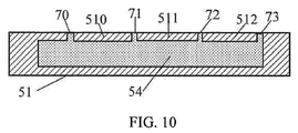
FIG. 10 is a schematic diagram of a lower bezel of a mobile terminal inFIG. 9 . - The following clearly and completely describes the technical solutions in the embodiment of the present invention with reference to the accompanying drawings in the embodiment of the present invention. Apparently, the described embodiment is merely one but not all of the embodiments of the present invention. All other embodiments obtained by a person of ordinary skill in the art based on the embodiment of the present invention without creative efforts shall fall within the protection scope of the present invention.
- As shown in
FIG. 1 , a mobile terminal according to an embodiment of the present invention includes a metalrear cover 1 used as a grounding component and an antenna, where the antenna includes agrounding pin 4, and thegrounding pin 4 is electrically connected to the metal rear cover. - The antenna includes an antenna component 8.
FIG. 1 schematically shows the antenna component 8, and the antenna component 8 may also be in other shapes, for example, anantenna component 80 shown inFIG. 3 . - Because the metal
rear cover 1 is used as the grounding component, and in this way, the metalrear cover 1 is used as a ground cable of the antenna, interference to the antenna from the metalrear cover 1 can be avoided, and integrity of the metalrear cover 1 can be further ensured. Moreover, it can be clearly seen from a rear view (FIG. 2 ) of the mobile terminal that an entire back of the mobile terminal is all-metal, which not only enables the mobile terminal to have good appearance, but also enables the whole mobile terminal to have relatively good metal texture. - To implement electrical connection between the grounding pin and the metal
rear cover 1 used as the grounding component, as an optional solution in this embodiment of the present invention, the grounding pin can be electrically connected to the metalrear cover 1 directly by means of a first electric conductor, where the first electric conductor may be an electrically conductive medium of a metal material category. -
FIG. 3 shows a front view of a mobile terminal according to an embodiment of the present invention. The mobile terminal includes a metalrear cover 1, as shown inFIG. 4 , used as a grounding component, adisplay 2, and an antenna, where the antenna is located between an edge of the display and an edge of the metal rear cover, and the antenna may be located on the top, the bottom, the left and the right of the mobile terminal. In the embodiment shown inFIG. 3 , antennas are disposed on the top, the bottom, and the right of the mobile terminal, and this embodiment of the present invention is described by separately using an upper antenna, a lower antenna, and a right antenna. - The mobile terminal according to this embodiment of the present invention further includes a printed circuit board (Printed Circuit Board, PCB) 9 accommodated between the metal
rear cover 1 and thedisplay 2.FIG. 3 shows a part of the printed circuit board, and the remaining part is not drawn inFIG. 3 . A radio frequency circuit, a feeding pad, a reference ground, and a grounding pad that are corresponding to each of the antennas are disposed on the printedcircuit board 9, and the reference ground or the grounding pad may be connected to the metal rear cover by means of an electrically conductive medium such as an electrically conductive adhesive, a metal dome, or a screw. - The lower antenna includes an
antenna component 80, afirst grounding pin 40, and afirst feeding pin 41. Theantenna component 80 is an independent metal component, that is, a separate component. Theantenna component 80 may be connected to the reference ground on the printedcircuit board 9 by means of thefirst grounding pin 40, so that theantenna component 80 is electrically connected to the metal rear cover by means of thefirst grounding pin 40. Theantenna component 80 is connected to the radio frequency circuit corresponding to theantenna component 80 on theprinted circuit board 9 by means of thefirst feeding pin 41. - As mentioned above, seen from the back, the mobile terminal in this embodiment of the present invention is all-mental. To make the whole mobile terminal look more of metal texture, bezels of a metal material may be disposed on the metal
rear cover 1. In this way, seen from both a side and a front, the mobile terminal has metal bright edges, so that the mobile terminal has more excellent appearance. Moreover, the bezels may be in a bending shape or in a shape similar to a straight shape shown inFIG. 1 , which is not limited in this embodiment of the present invention. - As shown in
FIG. 1 andFIG. 3 ,bezels 50 to 53 are disposed on the metalrear cover 1. As mentioned above, to make the whole mobile terminal more of metal texture, thebezels 50 to 53 may be of a metal material. Optionally, any bezel of thebezels 50 to 53 may be of a metal material, or be of a nonmetallic material, or be of both of a metal material and a nonmetallic material. - In the embodiment shown in
FIG. 3 , thebezels bezels - As shown in
FIG. 5 , thebezel 50 is a metal bezel that is grooved in the middle. As shown inFIG. 6 , for the sake of beauty, a nonmetallic material (as shown by 54) such as plastic may be embedded in a grooved position, and in this way, thebezel 50 is of both of the metal material and the nonmetallic material. - The upper antenna in
FIG. 3 includes an antenna component, asecond grounding pin 30, and asecond feeding pin 31. The antenna component is a metal structural component of thebezel 50. As shown inFIG. 5 , the antenna component is thebezel 50, and as shown inFIG. 6 , the antenna component is 501 on thebezel 50. The antenna component is connected to the reference ground on the printedcircuit board 9 by means of thesecond grounding pin 30 to implement electrical connection to the metal rear cover. The antenna component is connected to the radio frequency circuit corresponding to the upper antenna on the printedcircuit board 9 by means of the second feeding pin. - As shown in
FIG. 7 , to implement the right antenna, theside bezel 52 is of a metal material, and theside bezel 52 has a metalthin bezel 521. One end of the metal thin bezel is opened, that is, one end of the metalthin bezel 521 is agap 74. For the sake of beauty, as shown inFIG. 8 , the nonmetallic material (such as 54) may be embedded in a blank area of theside bezel 52, that is, theside bezel 52 is of both of the metal material and the nonmetallic material by using the embodiment shown inFIG. 8 . - The right antenna of the mobile terminal shown in
FIG. 3 includes anantenna component 521, athird grounding pin 60, and athird feeding pin 31. Theantenna component 521 is a part of a metal structural component of thebezel 52. Theantenna component 521 is connected to the reference ground on the printedcircuit board 9 by means of thethird grounding pin 60 to implement electrical connection to the metal rear cover. The antenna component is connected to the radio frequency circuit corresponding to the right antenna on the printedcircuit board 9 by means of the third feeding pin. - As shown in
FIG. 9, FIG. 9 is a view of a mobile terminal according to another embodiment of the present invention. The mobile terminal includes a metalrear cover 1 shown inFIG. 2 orFIG. 4 , adisplay screen 2, a printedcircuit board 9, and a lower antenna. Bezels are disposed around the metal rear cover, where alower bezel 51 includes a metal material and a nonmetallic material to form metalthin bezels FIG. 10 . The lower antenna includes an antenna component, afirst grounding pin 40, and asecond feeding pin 41. The antenna component includes anantenna wire 83, and the metalthin bezels FIG. 3 , the lower antenna shown inFIG. 9 utilizes a part of a metal structural component (the metalthin bezels 510 and 511) of thebezel 51, which can reduce space occupied by the lower antenna. - As shown in
FIG. 9 , a parasitic component of theantenna component 80 is disposed in a position that is close to, for example, 1 mm to 2 mm away from thefirst feeding pin 41. To implement performance of the specific parasitic component, a metalthin bezel 512 may be formed on thelower bezel 51, and anantenna wire 81 and the metalthin bezel 512 jointly implement a function of the parasitic component. A position of theantenna wire 81 and a position of agap 73 are set according to design needs of antenna performance. - It can be seen from the upper antenna and the right antenna in the embodiment shown in
FIG. 3 and the lower antenna shown inFIG. 9 that the antenna components are partially or completely the metal structural components of the bezels, which can reduce space occupied by the antennas. - In the embodiment of the present invention, because a metal rear cover is used as a grounding component, and in this way, the metal rear cover is used as a ground cable of an antenna, interference to the antenna from the metal rear cover can be avoided, and integrity of the metal rear cover can be further ensured. Moreover, it can be clearly seen from a rear view of a mobile terminal that an entire back of the mobile terminal is all-metal, which not only enables the mobile terminal to have good appearance, but also enables the whole mobile terminal to have relatively good metal texture.
- The foregoing descriptions are merely a specific embodiment of the present invention, but are not intended to limit the protection scope of the present invention. Any variation or replacement readily figured out by a person skilled in the art within the technical scope disclosed in the present invention shall fall within the protection scope of the present invention. Therefore, the protection scope of the present invention shall be subject to the protection scope of the claims.
Claims (10)
- A mobile terminal, comprising a metal rear cover used as a grounding component and at least one antenna, wherein the antenna comprises a grounding pin, and the grounding pin is electrically connected to the metal rear cover.
- The mobile terminal according to claim 1, wherein the grounding pin is electrically connected to the metal rear cover by means of a first electric conductor.
- The mobile terminal according to claim 1, further comprising a printed circuit board accommodated between the metal rear cover and the display, wherein a radio frequency circuit and the reference ground that are corresponding to the antenna are disposed on the printed circuit board, and the reference ground is connected to the metal rear cover.
- The mobile terminal according to claim 3, wherein that the grounding pin is electrically connected to the metal rear cover is specifically: the grounding pin is connected to the reference ground and is electrically connected to the metal rear cover by means of the reference ground.
- The mobile terminal according to claim 3 or claim 4, wherein the antenna further comprises a feeding pin, and the feeding pin is electrically connected to the radio frequency circuit corresponding to the antenna.
- The mobile terminal according to any one of claims 1 to 5, wherein the antenna further comprises an antenna component.
- The mobile terminal according to claim 6, wherein the antenna component is an independent metal component.
- The mobile terminal according to claim 6, wherein a bezel is disposed on the metal rear cover.
- The mobile terminal according to claim 8, wherein the antenna component is partially or completely made up of a metal structural component of the bezel.
- The mobile terminal according to claim 9, wherein that the antenna component is partially or completely made up of a metal structural component of the bezel is specifically: the antenna component is partially or completely made up of a part of the metal structural component of the bezel.
Applications Claiming Priority (2)
| Application Number | Priority Date | Filing Date | Title |
|---|---|---|---|
| CN2013101964974A CN103327144A (en) | 2013-05-22 | 2013-05-22 | Mobile terminal |
| PCT/CN2014/077949 WO2014187309A1 (en) | 2013-05-22 | 2014-05-21 | Mobile terminal |
Publications (3)
| Publication Number | Publication Date |
|---|---|
| EP3001649A1 true EP3001649A1 (en) | 2016-03-30 |
| EP3001649A4 EP3001649A4 (en) | 2016-07-06 |
| EP3001649B1 EP3001649B1 (en) | 2024-10-23 |
Family
ID=49195663
Family Applications (1)
| Application Number | Title | Priority Date | Filing Date |
|---|---|---|---|
| EP14801202.4A Active EP3001649B1 (en) | 2013-05-22 | 2014-05-21 | Mobile terminal |
Country Status (4)
| Country | Link |
|---|---|
| US (1) | US9899728B2 (en) |
| EP (1) | EP3001649B1 (en) |
| CN (1) | CN103327144A (en) |
| WO (1) | WO2014187309A1 (en) |
Cited By (1)
| Publication number | Priority date | Publication date | Assignee | Title |
|---|---|---|---|---|
| EP3324483A1 (en) * | 2016-11-18 | 2018-05-23 | Guangdong Oppo Mobile Telecommunications Corp., Ltd | Antenna device for mobile terminal and mobile terminal |
Families Citing this family (10)
| Publication number | Priority date | Publication date | Assignee | Title |
|---|---|---|---|---|
| KR101467196B1 (en) * | 2013-03-29 | 2014-12-01 | 주식회사 팬택 | Terminal including multiband antenna using conductive border |
| CN103327144A (en) | 2013-05-22 | 2013-09-25 | 华为终端有限公司 | Mobile terminal |
| CN104064866B (en) * | 2014-05-26 | 2018-08-17 | 普尔思(苏州)无线通讯产品有限公司 | Applied to the antenna structure of mobile phole simultaneously with becket and all-metal rear shell |
| CN105048087B (en) * | 2015-08-12 | 2018-05-15 | 宇龙计算机通信科技(深圳)有限公司 | Antenna for mobile phone |
| CN105161833B (en) * | 2015-08-12 | 2019-06-11 | 宇龙计算机通信科技(深圳)有限公司 | cell phone antenna |
| CN107293839A (en) * | 2016-03-31 | 2017-10-24 | 宇龙计算机通信科技(深圳)有限公司 | Design method, circular polarized antenna and the mobile terminal of circular polarized antenna |
| CN107395788B (en) | 2016-05-17 | 2021-03-23 | 北京小米移动软件有限公司 | Terminal shell and terminal |
| CN106654578A (en) * | 2016-12-13 | 2017-05-10 | 惠州Tcl移动通信有限公司 | Mobile terminal capable of improving antenna contact performance |
| CN110034402B (en) * | 2018-01-11 | 2021-11-23 | 深圳富泰宏精密工业有限公司 | Antenna structure and wireless communication device with same |
| CN208806357U (en) * | 2018-08-03 | 2019-04-30 | 瑞声光电科技(苏州)有限公司 | Antenna modules and mobile terminal |
Family Cites Families (11)
| Publication number | Priority date | Publication date | Assignee | Title |
|---|---|---|---|---|
| EP2095464A4 (en) * | 2006-11-16 | 2012-10-24 | Galtronics Ltd | Compact antenna |
| US7551142B1 (en) * | 2007-12-13 | 2009-06-23 | Apple Inc. | Hybrid antennas with directly fed antenna slots for handheld electronic devices |
| KR101157384B1 (en) | 2008-09-05 | 2012-06-20 | 애플 인크. | Handheld computing device |
| CN201282187Y (en) * | 2008-09-19 | 2009-07-29 | 耀登科技股份有限公司 | Loop antenna capable of using in metal casing or non-metal casing mobile phone |
| EP2355241A1 (en) * | 2010-02-02 | 2011-08-10 | Laird Technologies AB | An antenna device for a radio communication device |
| US20110254741A1 (en) * | 2010-04-16 | 2011-10-20 | Katsunori Ishimiya | Wireless communication device with housing member that functions as a radiating element of an antenna |
| CN201994985U (en) * | 2011-03-24 | 2011-09-28 | 广东欧珀移动通信有限公司 | A mobile phone built-in antenna device |
| JP5973151B2 (en) * | 2011-10-31 | 2016-08-23 | シャープ株式会社 | Conductive pattern forming housing, antenna device, continuity inspection method, continuity inspection jig, and antenna device manufacturing method |
| CN102522625B (en) * | 2011-11-22 | 2016-04-20 | 上海安费诺永亿通讯电子有限公司 | A kind of antenna structure of terminal of cellphone with metallic shell |
| CN103022689A (en) * | 2012-12-24 | 2013-04-03 | 上海安费诺永亿通讯电子有限公司 | Wide frequency antenna capable of serving as metal shell of mobile terminal |
| CN103327144A (en) * | 2013-05-22 | 2013-09-25 | 华为终端有限公司 | Mobile terminal |
-
2013
- 2013-05-22 CN CN2013101964974A patent/CN103327144A/en active Pending
-
2014
- 2014-05-21 WO PCT/CN2014/077949 patent/WO2014187309A1/en not_active Ceased
- 2014-05-21 EP EP14801202.4A patent/EP3001649B1/en active Active
-
2015
- 2015-11-20 US US14/947,042 patent/US9899728B2/en active Active
Cited By (3)
| Publication number | Priority date | Publication date | Assignee | Title |
|---|---|---|---|---|
| EP3324483A1 (en) * | 2016-11-18 | 2018-05-23 | Guangdong Oppo Mobile Telecommunications Corp., Ltd | Antenna device for mobile terminal and mobile terminal |
| US10312585B2 (en) | 2016-11-18 | 2019-06-04 | Guangdong Oppo Mobile Telecommunications Corp., Ltd. | Antenna device for mobile terminal and mobile terminal |
| US10707571B2 (en) | 2016-11-18 | 2020-07-07 | Guangdong Oppo Mobile Telecommunications Corp., Ltd. | Antenna device for mobile terminal and mobile terminal |
Also Published As
| Publication number | Publication date |
|---|---|
| US9899728B2 (en) | 2018-02-20 |
| US20160079659A1 (en) | 2016-03-17 |
| EP3001649B1 (en) | 2024-10-23 |
| EP3001649A4 (en) | 2016-07-06 |
| CN103327144A (en) | 2013-09-25 |
| WO2014187309A1 (en) | 2014-11-27 |
Similar Documents
| Publication | Publication Date | Title |
|---|---|---|
| US9899728B2 (en) | Mobile terminal | |
| CN112768904B (en) | Antenna radiator, antenna assembly and electronic equipment | |
| US10276938B2 (en) | Mobile terminal device | |
| CN106229674B (en) | Full frequency band metal frame antenna structure | |
| CN205583123U (en) | A metal battery cover mobile phone antenna and mobile phone | |
| CN205051738U (en) | Mobile communication device | |
| CN103811863A (en) | mobile device | |
| CN108879070B (en) | Electronic equipment | |
| WO2020135176A1 (en) | Radio electronic communication device | |
| US9674321B2 (en) | Mobile terminal antenna module housed within metal rear cover serving as a radiator | |
| US9509814B1 (en) | Mobile terminal | |
| CN105932397A (en) | Antenna device and communication equipment | |
| CN105024135A (en) | Cellphone antenna | |
| CN104347927B (en) | Antenna and hand-hold communication appliance | |
| CN203481380U (en) | Antenna used for mobile terminal, mobile terminal shell and the mobile terminal | |
| WO2017036050A1 (en) | Antenna apparatus of mobile terminal, and mobile terminal | |
| US20150171504A1 (en) | Electronic apparatus | |
| JP5521580B2 (en) | Portable wireless terminal | |
| CN109193116A (en) | Electronic device and control method of electronic device | |
| CN208738422U (en) | Antenna assemblies and electronic equipment | |
| CN204809380U (en) | Mobile phone antenna | |
| CN106654579B (en) | Design method of totally-enclosed metal frame mobile phone antenna capable of increasing thickness of antenna | |
| CN109066066A (en) | Antenna assembly and electronic equipment | |
| US11158932B2 (en) | Full screen electronic device and antenna thereof | |
| CN107293856A (en) | A kind of NFC antenna structure and mobile terminal |
Legal Events
| Date | Code | Title | Description |
|---|---|---|---|
| PUAI | Public reference made under article 153(3) epc to a published international application that has entered the european phase |
Free format text: ORIGINAL CODE: 0009012 |
|
| 17P | Request for examination filed |
Effective date: 20151202 |
|
| AK | Designated contracting states |
Kind code of ref document: A1 Designated state(s): AL AT BE BG CH CY CZ DE DK EE ES FI FR GB GR HR HU IE IS IT LI LT LU LV MC MK MT NL NO PL PT RO RS SE SI SK SM TR |
|
| AX | Request for extension of the european patent |
Extension state: BA ME |
|
| RIC1 | Information provided on ipc code assigned before grant |
Ipc: H01Q 1/48 20060101ALI20160525BHEP Ipc: H04M 1/02 20060101AFI20160525BHEP Ipc: H01Q 1/24 20060101ALI20160525BHEP Ipc: H01Q 21/28 20060101ALI20160525BHEP Ipc: H01Q 1/26 20060101ALI20160525BHEP |
|
| A4 | Supplementary search report drawn up and despatched |
Effective date: 20160602 |
|
| DAX | Request for extension of the european patent (deleted) | ||
| RAP1 | Party data changed (applicant data changed or rights of an application transferred) |
Owner name: HUAWEI DEVICE (DONGGUAN) CO., LTD. |
|
| STAA | Information on the status of an ep patent application or granted ep patent |
Free format text: STATUS: EXAMINATION IS IN PROGRESS |
|
| RAP1 | Party data changed (applicant data changed or rights of an application transferred) |
Owner name: HUAWEI DEVICE CO., LTD. |
|
| 17Q | First examination report despatched |
Effective date: 20190412 |
|
| REG | Reference to a national code |
Ref country code: DE Ipc: H01Q0001480000 Ref country code: DE Ref legal event code: R079 Ref document number: 602014091057 Country of ref document: DE Free format text: PREVIOUS MAIN CLASS: H04M0001020000 Ipc: H01Q0001480000 |
|
| GRAP | Despatch of communication of intention to grant a patent |
Free format text: ORIGINAL CODE: EPIDOSNIGR1 |
|
| STAA | Information on the status of an ep patent application or granted ep patent |
Free format text: STATUS: GRANT OF PATENT IS INTENDED |
|
| RIC1 | Information provided on ipc code assigned before grant |
Ipc: H04M 1/02 20060101ALN20240419BHEP Ipc: H01Q 1/24 20060101ALI20240419BHEP Ipc: H01Q 21/28 20060101ALI20240419BHEP Ipc: H01Q 1/48 20060101AFI20240419BHEP |
|
| RIC1 | Information provided on ipc code assigned before grant |
Ipc: H04M 1/02 20060101ALN20240502BHEP Ipc: H01Q 1/24 20060101ALI20240502BHEP Ipc: H01Q 21/28 20060101ALI20240502BHEP Ipc: H01Q 1/48 20060101AFI20240502BHEP |
|
| INTG | Intention to grant announced |
Effective date: 20240516 |
|
| GRAS | Grant fee paid |
Free format text: ORIGINAL CODE: EPIDOSNIGR3 |
|
| GRAA | (expected) grant |
Free format text: ORIGINAL CODE: 0009210 |
|
| STAA | Information on the status of an ep patent application or granted ep patent |
Free format text: STATUS: THE PATENT HAS BEEN GRANTED |
|
| AK | Designated contracting states |
Kind code of ref document: B1 Designated state(s): AL AT BE BG CH CY CZ DE DK EE ES FI FR GB GR HR HU IE IS IT LI LT LU LV MC MK MT NL NO PL PT RO RS SE SI SK SM TR |
|
| REG | Reference to a national code |
Ref country code: GB Ref legal event code: FG4D |
|
| REG | Reference to a national code |
Ref country code: CH Ref legal event code: EP |
|
| REG | Reference to a national code |
Ref country code: DE Ref legal event code: R096 Ref document number: 602014091057 Country of ref document: DE |
|
| REG | Reference to a national code |
Ref country code: IE Ref legal event code: FG4D |
|
| REG | Reference to a national code |
Ref country code: LT Ref legal event code: MG9D |
|
| REG | Reference to a national code |
Ref country code: NL Ref legal event code: MP Effective date: 20241023 |
|
| REG | Reference to a national code |
Ref country code: AT Ref legal event code: MK05 Ref document number: 1735612 Country of ref document: AT Kind code of ref document: T Effective date: 20241023 |
|
| PG25 | Lapsed in a contracting state [announced via postgrant information from national office to epo] |
Ref country code: NL Free format text: LAPSE BECAUSE OF FAILURE TO SUBMIT A TRANSLATION OF THE DESCRIPTION OR TO PAY THE FEE WITHIN THE PRESCRIBED TIME-LIMIT Effective date: 20241023 |
|
| PG25 | Lapsed in a contracting state [announced via postgrant information from national office to epo] |
Ref country code: NL Free format text: LAPSE BECAUSE OF FAILURE TO SUBMIT A TRANSLATION OF THE DESCRIPTION OR TO PAY THE FEE WITHIN THE PRESCRIBED TIME-LIMIT Effective date: 20241023 |
|
| PG25 | Lapsed in a contracting state [announced via postgrant information from national office to epo] |
Ref country code: PT Free format text: LAPSE BECAUSE OF FAILURE TO SUBMIT A TRANSLATION OF THE DESCRIPTION OR TO PAY THE FEE WITHIN THE PRESCRIBED TIME-LIMIT Effective date: 20250224 Ref country code: IS Free format text: LAPSE BECAUSE OF FAILURE TO SUBMIT A TRANSLATION OF THE DESCRIPTION OR TO PAY THE FEE WITHIN THE PRESCRIBED TIME-LIMIT Effective date: 20250223 Ref country code: HR Free format text: LAPSE BECAUSE OF FAILURE TO SUBMIT A TRANSLATION OF THE DESCRIPTION OR TO PAY THE FEE WITHIN THE PRESCRIBED TIME-LIMIT Effective date: 20241023 |
|
| PG25 | Lapsed in a contracting state [announced via postgrant information from national office to epo] |
Ref country code: FI Free format text: LAPSE BECAUSE OF FAILURE TO SUBMIT A TRANSLATION OF THE DESCRIPTION OR TO PAY THE FEE WITHIN THE PRESCRIBED TIME-LIMIT Effective date: 20241023 |
|
| PG25 | Lapsed in a contracting state [announced via postgrant information from national office to epo] |
Ref country code: BG Free format text: LAPSE BECAUSE OF FAILURE TO SUBMIT A TRANSLATION OF THE DESCRIPTION OR TO PAY THE FEE WITHIN THE PRESCRIBED TIME-LIMIT Effective date: 20241023 |
|
| PG25 | Lapsed in a contracting state [announced via postgrant information from national office to epo] |
Ref country code: ES Free format text: LAPSE BECAUSE OF FAILURE TO SUBMIT A TRANSLATION OF THE DESCRIPTION OR TO PAY THE FEE WITHIN THE PRESCRIBED TIME-LIMIT Effective date: 20241023 |
|
| PG25 | Lapsed in a contracting state [announced via postgrant information from national office to epo] |
Ref country code: NO Free format text: LAPSE BECAUSE OF FAILURE TO SUBMIT A TRANSLATION OF THE DESCRIPTION OR TO PAY THE FEE WITHIN THE PRESCRIBED TIME-LIMIT Effective date: 20250123 |
|
| PG25 | Lapsed in a contracting state [announced via postgrant information from national office to epo] |
Ref country code: LV Free format text: LAPSE BECAUSE OF FAILURE TO SUBMIT A TRANSLATION OF THE DESCRIPTION OR TO PAY THE FEE WITHIN THE PRESCRIBED TIME-LIMIT Effective date: 20241023 Ref country code: AT Free format text: LAPSE BECAUSE OF FAILURE TO SUBMIT A TRANSLATION OF THE DESCRIPTION OR TO PAY THE FEE WITHIN THE PRESCRIBED TIME-LIMIT Effective date: 20241023 Ref country code: GR Free format text: LAPSE BECAUSE OF FAILURE TO SUBMIT A TRANSLATION OF THE DESCRIPTION OR TO PAY THE FEE WITHIN THE PRESCRIBED TIME-LIMIT Effective date: 20250124 |
|
| PG25 | Lapsed in a contracting state [announced via postgrant information from national office to epo] |
Ref country code: PL Free format text: LAPSE BECAUSE OF FAILURE TO SUBMIT A TRANSLATION OF THE DESCRIPTION OR TO PAY THE FEE WITHIN THE PRESCRIBED TIME-LIMIT Effective date: 20241023 |
|
| PG25 | Lapsed in a contracting state [announced via postgrant information from national office to epo] |
Ref country code: RS Free format text: LAPSE BECAUSE OF FAILURE TO SUBMIT A TRANSLATION OF THE DESCRIPTION OR TO PAY THE FEE WITHIN THE PRESCRIBED TIME-LIMIT Effective date: 20250123 |
|
| PG25 | Lapsed in a contracting state [announced via postgrant information from national office to epo] |
Ref country code: SM Free format text: LAPSE BECAUSE OF FAILURE TO SUBMIT A TRANSLATION OF THE DESCRIPTION OR TO PAY THE FEE WITHIN THE PRESCRIBED TIME-LIMIT Effective date: 20241023 |
|
| PGFP | Annual fee paid to national office [announced via postgrant information from national office to epo] |
Ref country code: DE Payment date: 20250402 Year of fee payment: 12 |
|
| PG25 | Lapsed in a contracting state [announced via postgrant information from national office to epo] |
Ref country code: DK Free format text: LAPSE BECAUSE OF FAILURE TO SUBMIT A TRANSLATION OF THE DESCRIPTION OR TO PAY THE FEE WITHIN THE PRESCRIBED TIME-LIMIT Effective date: 20241023 |
|
| PGFP | Annual fee paid to national office [announced via postgrant information from national office to epo] |
Ref country code: GB Payment date: 20250401 Year of fee payment: 12 |
|
| PG25 | Lapsed in a contracting state [announced via postgrant information from national office to epo] |
Ref country code: EE Free format text: LAPSE BECAUSE OF FAILURE TO SUBMIT A TRANSLATION OF THE DESCRIPTION OR TO PAY THE FEE WITHIN THE PRESCRIBED TIME-LIMIT Effective date: 20241023 |
|
| PG25 | Lapsed in a contracting state [announced via postgrant information from national office to epo] |
Ref country code: RO Free format text: LAPSE BECAUSE OF FAILURE TO SUBMIT A TRANSLATION OF THE DESCRIPTION OR TO PAY THE FEE WITHIN THE PRESCRIBED TIME-LIMIT Effective date: 20241023 |
|
| REG | Reference to a national code |
Ref country code: DE Ref legal event code: R097 Ref document number: 602014091057 Country of ref document: DE |
|
| PG25 | Lapsed in a contracting state [announced via postgrant information from national office to epo] |
Ref country code: SK Free format text: LAPSE BECAUSE OF FAILURE TO SUBMIT A TRANSLATION OF THE DESCRIPTION OR TO PAY THE FEE WITHIN THE PRESCRIBED TIME-LIMIT Effective date: 20241023 |
|
| PG25 | Lapsed in a contracting state [announced via postgrant information from national office to epo] |
Ref country code: CZ Free format text: LAPSE BECAUSE OF FAILURE TO SUBMIT A TRANSLATION OF THE DESCRIPTION OR TO PAY THE FEE WITHIN THE PRESCRIBED TIME-LIMIT Effective date: 20241023 |
|
| PG25 | Lapsed in a contracting state [announced via postgrant information from national office to epo] |
Ref country code: IT Free format text: LAPSE BECAUSE OF FAILURE TO SUBMIT A TRANSLATION OF THE DESCRIPTION OR TO PAY THE FEE WITHIN THE PRESCRIBED TIME-LIMIT Effective date: 20241023 |
|
| PLBE | No opposition filed within time limit |
Free format text: ORIGINAL CODE: 0009261 |
|
| STAA | Information on the status of an ep patent application or granted ep patent |
Free format text: STATUS: NO OPPOSITION FILED WITHIN TIME LIMIT |
|
| PG25 | Lapsed in a contracting state [announced via postgrant information from national office to epo] |
Ref country code: SE Free format text: LAPSE BECAUSE OF FAILURE TO SUBMIT A TRANSLATION OF THE DESCRIPTION OR TO PAY THE FEE WITHIN THE PRESCRIBED TIME-LIMIT Effective date: 20241023 |
|
| 26N | No opposition filed |
Effective date: 20250724 |
|
| REG | Reference to a national code |
Ref country code: CH Ref legal event code: H13 Free format text: ST27 STATUS EVENT CODE: U-0-0-H10-H13 (AS PROVIDED BY THE NATIONAL OFFICE) Effective date: 20251223 |
|
| PG25 | Lapsed in a contracting state [announced via postgrant information from national office to epo] |
Ref country code: LU Free format text: LAPSE BECAUSE OF NON-PAYMENT OF DUE FEES Effective date: 20250521 |
|
| PG25 | Lapsed in a contracting state [announced via postgrant information from national office to epo] |
Ref country code: CH Free format text: LAPSE BECAUSE OF NON-PAYMENT OF DUE FEES Effective date: 20250531 |
|
| REG | Reference to a national code |
Ref country code: BE Ref legal event code: MM Effective date: 20250531 |
|
| PG25 | Lapsed in a contracting state [announced via postgrant information from national office to epo] |
Ref country code: MC Free format text: LAPSE BECAUSE OF FAILURE TO SUBMIT A TRANSLATION OF THE DESCRIPTION OR TO PAY THE FEE WITHIN THE PRESCRIBED TIME-LIMIT Effective date: 20241023 |
|
| PG25 | Lapsed in a contracting state [announced via postgrant information from national office to epo] |
Ref country code: IE Free format text: LAPSE BECAUSE OF NON-PAYMENT OF DUE FEES Effective date: 20250521 |
|
| PG25 | Lapsed in a contracting state [announced via postgrant information from national office to epo] |
Ref country code: BE Free format text: LAPSE BECAUSE OF NON-PAYMENT OF DUE FEES Effective date: 20250531 |
|
| PG25 | Lapsed in a contracting state [announced via postgrant information from national office to epo] |
Ref country code: FR Free format text: LAPSE BECAUSE OF NON-PAYMENT OF DUE FEES Effective date: 20250531 |