EP3001505A1 - Antenna system - Google Patents
Antenna system Download PDFInfo
- Publication number
- EP3001505A1 EP3001505A1 EP15150171.5A EP15150171A EP3001505A1 EP 3001505 A1 EP3001505 A1 EP 3001505A1 EP 15150171 A EP15150171 A EP 15150171A EP 3001505 A1 EP3001505 A1 EP 3001505A1
- Authority
- EP
- European Patent Office
- Prior art keywords
- antenna
- branch
- antenna system
- coupled
- ground region
- Prior art date
- Legal status (The legal status is an assumption and is not a legal conclusion. Google has not performed a legal analysis and makes no representation as to the accuracy of the status listed.)
- Withdrawn
Links
- 230000005855 radiation Effects 0.000 claims description 20
- 238000002955 isolation Methods 0.000 claims description 19
- 238000010586 diagram Methods 0.000 description 10
- 238000004891 communication Methods 0.000 description 4
- 230000008878 coupling Effects 0.000 description 4
- 238000010168 coupling process Methods 0.000 description 4
- 238000005859 coupling reaction Methods 0.000 description 4
- 238000013461 design Methods 0.000 description 4
- 238000010295 mobile communication Methods 0.000 description 3
- 238000005516 engineering process Methods 0.000 description 1
- 230000002708 enhancing effect Effects 0.000 description 1
- 238000010348 incorporation Methods 0.000 description 1
- 230000007774 longterm Effects 0.000 description 1
- 238000005259 measurement Methods 0.000 description 1
- 239000002184 metal Substances 0.000 description 1
- 238000000034 method Methods 0.000 description 1
- 238000012986 modification Methods 0.000 description 1
- 230000004048 modification Effects 0.000 description 1
- 230000005404 monopole Effects 0.000 description 1
- 230000002123 temporal effect Effects 0.000 description 1
Images


Classifications
-
- H—ELECTRICITY
- H01—ELECTRIC ELEMENTS
- H01Q—ANTENNAS, i.e. RADIO AERIALS
- H01Q1/00—Details of, or arrangements associated with, antennas
- H01Q1/52—Means for reducing coupling between antennas; Means for reducing coupling between an antenna and another structure
- H01Q1/521—Means for reducing coupling between antennas; Means for reducing coupling between an antenna and another structure reducing the coupling between adjacent antennas
-
- H—ELECTRICITY
- H01—ELECTRIC ELEMENTS
- H01Q—ANTENNAS, i.e. RADIO AERIALS
- H01Q1/00—Details of, or arrangements associated with, antennas
- H01Q1/52—Means for reducing coupling between antennas; Means for reducing coupling between an antenna and another structure
- H01Q1/526—Electromagnetic shields
-
- H—ELECTRICITY
- H01—ELECTRIC ELEMENTS
- H01Q—ANTENNAS, i.e. RADIO AERIALS
- H01Q1/00—Details of, or arrangements associated with, antennas
- H01Q1/12—Supports; Mounting means
- H01Q1/22—Supports; Mounting means by structural association with other equipment or articles
- H01Q1/24—Supports; Mounting means by structural association with other equipment or articles with receiving set
- H01Q1/241—Supports; Mounting means by structural association with other equipment or articles with receiving set used in mobile communications, e.g. GSM
- H01Q1/242—Supports; Mounting means by structural association with other equipment or articles with receiving set used in mobile communications, e.g. GSM specially adapted for hand-held use
- H01Q1/243—Supports; Mounting means by structural association with other equipment or articles with receiving set used in mobile communications, e.g. GSM specially adapted for hand-held use with built-in antennas
-
- H—ELECTRICITY
- H01—ELECTRIC ELEMENTS
- H01Q—ANTENNAS, i.e. RADIO AERIALS
- H01Q21/00—Antenna arrays or systems
- H01Q21/28—Combinations of substantially independent non-interacting antenna units or systems
Definitions
- the disclosure generally relates to an antenna system, and more particularly, to an antenna system for improving isolation.
- mobile devices such as portable computers, mobile phones, multimedia players, and other hybrid functional portable electronic devices have become more common.
- mobile devices can usually perform wireless communication functions.
- Some devices cover a large wireless communication area; these include mobile phones using 2G, 3G, and LTE (Long Term Evolution) systems and using frequency bands of 700MHz, 850MHz, 900MHz, 1800MHz, 1900MHz, 2100MHz, 2300MHz, and 2500MHz.
- Some devices cover a small wireless communication area; these include mobile phones using Wi-Fi and Bluetooth systems and using frequency bands of 2.4GHz, 3.5GHz, 5.2GHz, and 5.8GHz.
- An antenna system is indispensable in a mobile device supporting wireless communication.
- the interior space of a mobile device is very limited, multiple antennas are usually disposed close to each other, and such a design causes serious interference between antennas.
- the invention is directed to an antenna system, including: a first antenna, excited by a first signal source; a second antenna, excited by a second signal source; and a bridge element, disposed between the first antenna and the second antenna, wherein two ends of the bridge element are both coupled to a ground region.
- the bridge element is configured to improve isolation between the first antenna and the second antenna.
- the bridge element includes a first branch and a second branch, a first end of the first branch is coupled to the ground region, a first end of the second branch is coupled to the ground region, and a second end of the first branch is coupled to a second end of the second branch.
- a combination of the first branch and the second branch substantially has an inverted U-shape.
- the bridge element further includes an additional branch, and the additional branch is coupled to the second end of the first branch and the second end of the second branch.
- the additional branch substantially has a straight-line shape and extends away from the ground region.
- the additional branch substantially has a meandering shape and extends toward the ground region.
- the first antenna and the second antenna are coupling-feed antennas.
- the first antenna includes a first feeding element and a first radiation element, a first end of the first feeding element is coupled to the first signal source, a second end of the first feeding element is open, a first end of the first radiation element is adjacent to the second end of the first feeding element, a second end of the first radiation element is coupled to the ground region
- the second antenna includes a second feeding element and a second radiation element, a first end of the second feeding element is coupled to the second signal source, a second end of the second feeding element is open, a first end of the second radiation element is adjacent to the second end of the second feeding element, and a second end of the second radiation element is coupled to the ground region.
- the first antenna, the second antenna, and the bridge element all operate in a first frequency band and a second frequency band, the first frequency band is substantially from 2400
- FIG. 1 is a diagram of an antenna system 100 according to an embodiment of the invention.
- the antenna system 100 may be applied in a mobile device, such as a smartphone, a tablet computer, or a notebook computer.
- the antenna system 100 includes a first antenna 110, a second antenna 120, a first signal source 130, a second signal source 140, and a bridge element 150.
- the types of the first antenna 110 and the second antenna 120 are not limited in the invention.
- any of the first antenna 110 and the second antenna 120 may be a coupling-feed antenna, a monopole antenna, a dipole antenna, a loop antenna, or a helical antenna.
- the first signal source 130 and the second signal source 140 may be RF (Radio Frequency) modules.
- the first antenna 110 is excited by the first signal source 130, and the second antenna 120 is excited by the second signal source 140.
- the bridge element 150 is disposed between the first antenna 110 and the second antenna 120. Two ends of the bridge element 150 are both coupled to a ground region 160.
- the ground region 160 may be a metal ground plane of a mobile device, and it may be configured to provide a ground voltage.
- the bridge element 150 directly reduces the electromagnetic interference between the first antenna 110 and the second antenna 120, thereby effectively improving the isolation between the first antenna 110 and the second antenna 120.
- a conventional antenna system usually maintains the isolation by increasing spacing between antennas.
- the invention uses the bridge element 150, rather than the conventional design, and it not only keeps good antenna performance but also saves design space.
- FIG. 2 is a diagram of an antenna system 200 according to an embodiment of the invention.
- the antenna system 200 includes a first antenna 210, a second antenna 220, a first signal source 130, a second signal source 140, and a bridge element 150.
- the first antenna 210 and the second antenna 220 are both coupling-feed antennas.
- the bridge element 150 includes a first branch 151 and a second branch 152. A first end 153 of the first branch 151 is coupled to a ground region 160. A first end 155 of the second branch 152 is coupled to the ground region 160.
- a second end 154 of the first branch 151 is coupled to a second end 156 of the second branch 152.
- a combination of the first branch 151 and the second branch 152 substantially has an inverted U-shape.
- the inverted U-shape has two right-angle turns, such that at least portions of the first branch 151 and the second branch 152 are parallel to each other.
- the bridge element 150 is configured to improve the isolation between the first antenna 210 and the second antenna 220.
- the first antenna 210 includes a first feeding element 211 and a first radiation element 212.
- a first end 213 of the first feeding element 211 is coupled to the first signal source 130.
- a second end 214 of the first feeding element 211 is open.
- a first end 215 of the first radiation element 212 is adjacent to the second end 214 of the first feeding element 211.
- a second end 216 of the first radiation element 212 is coupled to the ground region 160.
- the width of a first coupling gap GC1 between the second end 214 of the first feeding element 211 and the first end 215 of the first radiation element 212 is substantially from 1mm to 1.5mm.
- the second antenna 220 includes a second feeding element 221 and a second radiation element 222.
- a first end 223 of the second feeding element 221 is coupled to the second signal source 140.
- a second end 224 of the second feeding element 221 is open.
- a first end 225 of the second radiation element 222 is adjacent to the second end 224 of the second feeding element 221.
- a second end 226 of the second radiation element 222 is coupled to the ground region 160.
- the width of a second coupling gap GC2 between the second end 224 of the second feeding element 221 and the first end 225 of the second radiation element 222 is substantially from 1mm to 1.5mm.
- the width of a third coupling gap GC3 between the first antenna 210 and the bridge element 150 is substantially from 1mm to 2mm, and the width of a fourth coupling gap GC4 between the second antenna 220 and the bridge element 150 is also substantially from 1mm to 2mm, such that the first antenna 210 and the second antenna can indirectly communicate with each other through the bridge element 150.
- FIG. 3 is a diagram of an antenna system 300 according to an embodiment of the invention.
- FIG. 3 is similar to FIG. 2 .
- the difference between the two embodiments is that a bridge element 350 of the antenna system 300 further includes an additional branch 357.
- the additional branch 357 is configured to improve the isolation between the first antenna 210 and the second antenna 220 in the low-frequency bands.
- the length of the additional branch 357 is substantially from 0.25 to 0.5 wavelengths of a central operating frequency of the low-frequency bands.
- the additional branch 357 is coupled to the second end 154 of the first branch 151 and the second end 156 of the second branch 152 (i.e., the additional branch 357 is coupled to the junction point between the first branch 151 and the second branch 152).
- the additional branch 357 substantially has a straight-line shape and is substantially perpendicular to the first branch 151 and the second branch 152.
- the additional branch 357 extends away from the ground region 160.
- a combination of the additional branch 357, the first branch 151, and the second branch 152 of the bridge element 350 substantially has an inverted Y-shape.
- Other features of the antenna system 300 of FIG. 3 are similar to those of the antenna system 200 of FIG. 2 . Accordingly, the two embodiments can achieve similar levels of performance.
- FIG. 4 is a diagram of an antenna system 400 according to an embodiment of the invention.
- FIG. 4 is similar to FIG. 2 .
- the difference between the two embodiments is that a bridge element 450 of the antenna system 400 further includes an additional branch 457.
- the additional branch 457 is configured to improve the isolation between the first antenna 210 and the second antenna 220 in the low-frequency bands.
- the length of the additional branch 457 is substantially from 0.25 to 0.5 wavelengths of a central operating frequency of the low-frequency bands.
- the additional branch 457 is coupled to the second end 154 of the first branch 151 and the second end 156 of the second branch 152 (i.e., the additional branch 457 is coupled to the junction point between the first branch 151 and the second branch 152).
- the additional branch 457 substantially has a meandering shape and extends toward the ground region 160.
- the additional branch 457 includes at least two S-shapes connected to each other.
- Other features of the antenna system 400 of FIG. 4 are similar to those of the antenna system 200 of FIG. 2 . Accordingly, the two embodiments can achieve similar levels of performance.
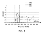
- FIG. 5 is a diagram of isolation of an antenna system according to an embodiment of the invention.
- the horizontal axis represents the operating frequency (MHz), and the vertical axis represents the isolation (S21) (dB) between antennas.
- the first antenna, the second antenna, and the bridge element all operate in a first frequency band and a second frequency band.
- the first frequency band may be substantially from 2400MHz to 2500MHz, and the second frequency band may be substantially from 5150MHz to 5850MHz.
- the antenna system of the invention at least supports the mobile communication bands of Wi-Fi and Bluetooth.
- the first curve CC1 means the isolation of the antenna system without any bridge element
- the second curve CC2 means the isolation of the antenna system with the bridge element of FIG.
- the bridge element of the invention can effectively improve the isolation of the antenna system in the low-frequency operating bands (e.g., the first frequency band).
- the antenna system of the invention has at least -15dB isolation in the above operating frequency bands, and such isolation meets the general requirements of mobile communication standards. More particularly, the incorporation of the bridge element substantially improves the isolation of the antenna system by about 8 to 20dB, without increasing spacing between antennas additionally. Therefore, the invention has at least the advantages of enhancing the antenna system performance and minimizing the total antenna-system area, and it is suitable for application in a variety of mobile devices with small inner space.
- the spacing between the first antenna and the second antenna is about 30mm, and the total length of the additional branch of the bridge element is about 27mm.
- element sizes, element shapes, and frequency ranges are not limitations of the invention. An antenna designer can fine-tune these settings or values according to different requirements. It should be understood that the antenna system of the invention is not limited to the configurations of FIGS. 1-5 . The invention may merely include any one or more features of any one or more embodiments of FIGS. 1-5 . In other words, not all of the features displayed in the figures should be implemented in the antenna system of the invention.
Landscapes
- Physics & Mathematics (AREA)
- Electromagnetism (AREA)
- Variable-Direction Aerials And Aerial Arrays (AREA)
Abstract
Description
- This Application claims priority of Taiwan Patent Application No.
103133446 filed on September 26, 2014 - The disclosure generally relates to an antenna system, and more particularly, to an antenna system for improving isolation.
- With the advancement of mobile communication technology, mobile devices such as portable computers, mobile phones, multimedia players, and other hybrid functional portable electronic devices have become more common. To satisfy the demands of users, mobile devices can usually perform wireless communication functions. Some devices cover a large wireless communication area; these include mobile phones using 2G, 3G, and LTE (Long Term Evolution) systems and using frequency bands of 700MHz, 850MHz, 900MHz, 1800MHz, 1900MHz, 2100MHz, 2300MHz, and 2500MHz. Some devices cover a small wireless communication area; these include mobile phones using Wi-Fi and Bluetooth systems and using frequency bands of 2.4GHz, 3.5GHz, 5.2GHz, and 5.8GHz.
- An antenna system is indispensable in a mobile device supporting wireless communication. However, since the interior space of a mobile device is very limited, multiple antennas are usually disposed close to each other, and such a design causes serious interference between antennas. As a result, there is a need to design a new antenna system for solving the problem of bad isolation in a conventional antenna system.
- In a preferred embodiment, the invention is directed to an antenna system, including: a first antenna, excited by a first signal source; a second antenna, excited by a second signal source; and a bridge element, disposed between the first antenna and the second antenna, wherein two ends of the bridge element are both coupled to a ground region.
- In some embodiments, the bridge element is configured to improve isolation between the first antenna and the second antenna. In some embodiments, the bridge element includes a first branch and a second branch, a first end of the first branch is coupled to the ground region, a first end of the second branch is coupled to the ground region, and a second end of the first branch is coupled to a second end of the second branch. In some embodiments, a combination of the first branch and the second branch substantially has an inverted U-shape. In some embodiments, the bridge element further includes an additional branch, and the additional branch is coupled to the second end of the first branch and the second end of the second branch. In some embodiments, the additional branch substantially has a straight-line shape and extends away from the ground region. In some embodiments, the additional branch substantially has a meandering shape and extends toward the ground region. In some embodiments, the first antenna and the second antenna are coupling-feed antennas. In some embodiments, the first antenna includes a first feeding element and a first radiation element, a first end of the first feeding element is coupled to the first signal source, a second end of the first feeding element is open, a first end of the first radiation element is adjacent to the second end of the first feeding element, a second end of the first radiation element is coupled to the ground region, the second antenna includes a second feeding element and a second radiation element, a first end of the second feeding element is coupled to the second signal source, a second end of the second feeding element is open, a first end of the second radiation element is adjacent to the second end of the second feeding element, and a second end of the second radiation element is coupled to the ground region. In some embodiments, the first antenna, the second antenna, and the bridge element all operate in a first frequency band and a second frequency band, the first frequency band is substantially from 2400MHz to 2500MHz, and the second frequency band is substantially from 5150MHz to 5850MHz.
- The invention can be more fully understood by reading the subsequent detailed description and examples with references made to the accompanying drawings, wherein:
-
FIG. 1 is a diagram of an antenna system according to an embodiment of the invention; -
FIG. 2 is a diagram of an antenna system according to an embodiment of the invention; -
FIG. 3 is a diagram of an antenna system according to an embodiment of the invention; -
FIG. 4 is a diagram of an antenna system according to an embodiment of the invention; and -
FIG. 5 is a diagram of isolation of an antenna system according to an embodiment of the invention. - In order to illustrate the foregoing and other purposes, features and advantages of the invention, the embodiments and figures of the invention will be described in detail as follows.
-
FIG. 1 is a diagram of anantenna system 100 according to an embodiment of the invention. Theantenna system 100 may be applied in a mobile device, such as a smartphone, a tablet computer, or a notebook computer. As shown inFIG. 1 , theantenna system 100 includes afirst antenna 110, asecond antenna 120, afirst signal source 130, asecond signal source 140, and abridge element 150. The types of thefirst antenna 110 and thesecond antenna 120 are not limited in the invention. For example, any of thefirst antenna 110 and thesecond antenna 120 may be a coupling-feed antenna, a monopole antenna, a dipole antenna, a loop antenna, or a helical antenna. Thefirst signal source 130 and thesecond signal source 140 may be RF (Radio Frequency) modules. Thefirst antenna 110 is excited by thefirst signal source 130, and thesecond antenna 120 is excited by thesecond signal source 140. Thebridge element 150 is disposed between thefirst antenna 110 and thesecond antenna 120. Two ends of thebridge element 150 are both coupled to aground region 160. Theground region 160 may be a metal ground plane of a mobile device, and it may be configured to provide a ground voltage. After thebridge element 150 is incorporated into theantenna system 100, thebridge element 150 directly reduces the electromagnetic interference between thefirst antenna 110 and thesecond antenna 120, thereby effectively improving the isolation between thefirst antenna 110 and thesecond antenna 120. In comparison, a conventional antenna system usually maintains the isolation by increasing spacing between antennas. The invention uses thebridge element 150, rather than the conventional design, and it not only keeps good antenna performance but also saves design space. -
FIG. 2 is a diagram of anantenna system 200 according to an embodiment of the invention. In the embodiment ofFIG. 2 , theantenna system 200 includes afirst antenna 210, asecond antenna 220, afirst signal source 130, asecond signal source 140, and abridge element 150. As shown inFIG. 2 , thefirst antenna 210 and thesecond antenna 220 are both coupling-feed antennas. It should be understood that the antenna shapes shown in the figures are just exemplary, rather than limitations of the invention. Thebridge element 150 includes afirst branch 151 and asecond branch 152. Afirst end 153 of thefirst branch 151 is coupled to aground region 160. Afirst end 155 of thesecond branch 152 is coupled to theground region 160. Asecond end 154 of thefirst branch 151 is coupled to asecond end 156 of thesecond branch 152. A combination of thefirst branch 151 and thesecond branch 152 substantially has an inverted U-shape. In some embodiments, the inverted U-shape has two right-angle turns, such that at least portions of thefirst branch 151 and thesecond branch 152 are parallel to each other. Similarly, thebridge element 150 is configured to improve the isolation between thefirst antenna 210 and thesecond antenna 220. - More particularly, the
first antenna 210 includes afirst feeding element 211 and afirst radiation element 212. Afirst end 213 of thefirst feeding element 211 is coupled to thefirst signal source 130. Asecond end 214 of thefirst feeding element 211 is open. Afirst end 215 of thefirst radiation element 212 is adjacent to thesecond end 214 of thefirst feeding element 211. Asecond end 216 of thefirst radiation element 212 is coupled to theground region 160. In some embodiments, the width of a first coupling gap GC1 between thesecond end 214 of thefirst feeding element 211 and thefirst end 215 of thefirst radiation element 212 is substantially from 1mm to 1.5mm. Thesecond antenna 220 includes asecond feeding element 221 and asecond radiation element 222. Afirst end 223 of thesecond feeding element 221 is coupled to thesecond signal source 140. Asecond end 224 of thesecond feeding element 221 is open. Afirst end 225 of thesecond radiation element 222 is adjacent to thesecond end 224 of thesecond feeding element 221. Asecond end 226 of thesecond radiation element 222 is coupled to theground region 160. In some embodiments, the width of a second coupling gap GC2 between thesecond end 224 of thesecond feeding element 221 and thefirst end 225 of thesecond radiation element 222 is substantially from 1mm to 1.5mm. The width of a third coupling gap GC3 between thefirst antenna 210 and thebridge element 150 is substantially from 1mm to 2mm, and the width of a fourth coupling gap GC4 between thesecond antenna 220 and thebridge element 150 is also substantially from 1mm to 2mm, such that thefirst antenna 210 and the second antenna can indirectly communicate with each other through thebridge element 150. -
FIG. 3 is a diagram of anantenna system 300 according to an embodiment of the invention.FIG. 3 is similar toFIG. 2 . The difference between the two embodiments is that abridge element 350 of theantenna system 300 further includes anadditional branch 357. Theadditional branch 357 is configured to improve the isolation between thefirst antenna 210 and thesecond antenna 220 in the low-frequency bands. The length of theadditional branch 357 is substantially from 0.25 to 0.5 wavelengths of a central operating frequency of the low-frequency bands. Theadditional branch 357 is coupled to thesecond end 154 of thefirst branch 151 and thesecond end 156 of the second branch 152 (i.e., theadditional branch 357 is coupled to the junction point between thefirst branch 151 and the second branch 152). Theadditional branch 357 substantially has a straight-line shape and is substantially perpendicular to thefirst branch 151 and thesecond branch 152. Theadditional branch 357 extends away from theground region 160. A combination of theadditional branch 357, thefirst branch 151, and thesecond branch 152 of thebridge element 350 substantially has an inverted Y-shape. Other features of theantenna system 300 ofFIG. 3 are similar to those of theantenna system 200 ofFIG. 2 . Accordingly, the two embodiments can achieve similar levels of performance. -
FIG. 4 is a diagram of anantenna system 400 according to an embodiment of the invention.FIG. 4 is similar toFIG. 2 . The difference between the two embodiments is that abridge element 450 of theantenna system 400 further includes anadditional branch 457. Theadditional branch 457 is configured to improve the isolation between thefirst antenna 210 and thesecond antenna 220 in the low-frequency bands. The length of theadditional branch 457 is substantially from 0.25 to 0.5 wavelengths of a central operating frequency of the low-frequency bands. Theadditional branch 457 is coupled to thesecond end 154 of thefirst branch 151 and thesecond end 156 of the second branch 152 (i.e., theadditional branch 457 is coupled to the junction point between thefirst branch 151 and the second branch 152). Theadditional branch 457 substantially has a meandering shape and extends toward theground region 160. Theadditional branch 457 includes at least two S-shapes connected to each other. Other features of theantenna system 400 ofFIG. 4 are similar to those of theantenna system 200 ofFIG. 2 . Accordingly, the two embodiments can achieve similar levels of performance. -
FIG. 5 is a diagram of isolation of an antenna system according to an embodiment of the invention. The horizontal axis represents the operating frequency (MHz), and the vertical axis represents the isolation (S21) (dB) between antennas. In some embodiments, the first antenna, the second antenna, and the bridge element all operate in a first frequency band and a second frequency band. The first frequency band may be substantially from 2400MHz to 2500MHz, and the second frequency band may be substantially from 5150MHz to 5850MHz. The antenna system of the invention at least supports the mobile communication bands of Wi-Fi and Bluetooth. As shown inFIG. 5 , the first curve CC1 means the isolation of the antenna system without any bridge element, the second curve CC2 means the isolation of the antenna system with the bridge element ofFIG. 3 , and the third curve CC3 means the isolation of the antenna system with the bridge element ofFIG. 4 . According to the measurement ofFIG. 5 , it is noted that the bridge element of the invention can effectively improve the isolation of the antenna system in the low-frequency operating bands (e.g., the first frequency band). The antenna system of the invention has at least -15dB isolation in the above operating frequency bands, and such isolation meets the general requirements of mobile communication standards. More particularly, the incorporation of the bridge element substantially improves the isolation of the antenna system by about 8 to 20dB, without increasing spacing between antennas additionally. Therefore, the invention has at least the advantages of enhancing the antenna system performance and minimizing the total antenna-system area, and it is suitable for application in a variety of mobile devices with small inner space. - With regard to element sizes, the spacing between the first antenna and the second antenna is about 30mm, and the total length of the additional branch of the bridge element is about 27mm. Note that the above element sizes, element shapes, and frequency ranges are not limitations of the invention. An antenna designer can fine-tune these settings or values according to different requirements. It should be understood that the antenna system of the invention is not limited to the configurations of
FIGS. 1-5 . The invention may merely include any one or more features of any one or more embodiments ofFIGS. 1-5 . In other words, not all of the features displayed in the figures should be implemented in the antenna system of the invention. - Use of ordinal terms such as "first", "second", "third", etc., in the claims to modify a claim element does not by itself connote any priority, precedence, or order of one claim element over another or the temporal order in which acts of a method are performed, but are used merely as labels to distinguish one claim element having a certain name from another element having the same name (but for use of the ordinal term) to distinguish the claim elements.
- It will be apparent to those skilled in the art that various modifications and variations can be made in the invention. It is intended that the standard and examples be considered as exemplary only, with a true scope of the disclosed embodiments being indicated by the following claims and their equivalents.
Claims (10)
- An antenna system, comprising:a first antenna, excited by a first signal source;a second antenna, excited by a second signal source; anda bridge element, disposed between the first antenna and the second antenna, wherein two ends of the bridge element are both coupled to a ground region.
- The antenna system as claimed in claim 1, wherein the bridge element is configured to improve isolation between the first antenna and the second antenna.
- The antenna system as claimed in claim 1 or 2, wherein the bridge element comprises a first branch and a second branch, a first end of the first branch is coupled to the ground region, a first end of the second branch is coupled to the ground region, and a second end of the first branch is coupled to a second end of the second branch.
- The antenna system as claimed in claim 3, wherein a combination of the first branch and the second branch substantially has an inverted U-shape.
- The antenna system as claimed in claim 3 or 4, wherein the bridge element further comprises an additional branch, and the additional branch is coupled to the second end of the first branch and the second end of the second branch.
- The antenna system as claimed in claim 5, wherein the additional branch substantially has a straight-line shape and extends away from the ground region.
- The antenna system as claimed in claim 5, wherein the additional branch substantially has a meandering shape and extends toward the ground region.
- The antenna system as claimed in any of claims 1 to 7, wherein the first antenna and the second antenna are coupling-feed antennas.
- The antenna system as claimed in any of claims 1 to 8, wherein the first antenna comprises a first feeding element and a first radiation element, a first end of the first feeding element is coupled to the first signal source, a second end of the first feeding element is open, a first end of the first radiation element is adjacent to the second end of the first feeding element, a second end of the first radiation element is coupled to the ground region, the second antenna comprises a second feeding element and a second radiation element, a first end of the second feeding element is coupled to the second signal source, a second end of the second feeding element is open, a first end of the second radiation element is adjacent to the second end of the second feeding element, and a second end of the second radiation element is coupled to the ground region.
- The antenna system as claimed in any of claims 1 to 9, wherein the first antenna, the second antenna, and the bridge element all operate in a first frequency band and a second frequency band, the first frequency band is substantially from 2400MHz to 2500MHz, and the second frequency band is substantially from 5150MHz to 5850MHz.
Applications Claiming Priority (1)
| Application Number | Priority Date | Filing Date | Title |
|---|---|---|---|
| TW103133446A TWI539674B (en) | 2014-09-26 | 2014-09-26 | Antenna system |
Publications (1)
| Publication Number | Publication Date |
|---|---|
| EP3001505A1 true EP3001505A1 (en) | 2016-03-30 |
Family
ID=52146413
Family Applications (1)
| Application Number | Title | Priority Date | Filing Date |
|---|---|---|---|
| EP15150171.5A Withdrawn EP3001505A1 (en) | 2014-09-26 | 2015-01-06 | Antenna system |
Country Status (3)
| Country | Link |
|---|---|
| US (1) | US20160093949A1 (en) |
| EP (1) | EP3001505A1 (en) |
| TW (1) | TWI539674B (en) |
Cited By (2)
| Publication number | Priority date | Publication date | Assignee | Title |
|---|---|---|---|---|
| CN108172996A (en) * | 2017-12-27 | 2018-06-15 | 维沃移动通信有限公司 | A kind of mobile radio terminal |
| CN109314313A (en) * | 2016-06-14 | 2019-02-05 | 三菱电机株式会社 | Array Antenna Device |
Families Citing this family (16)
| Publication number | Priority date | Publication date | Assignee | Title |
|---|---|---|---|---|
| GB201610113D0 (en) | 2016-06-09 | 2016-07-27 | Smart Antenna Tech Ltd | An antenna system for a portable device |
| TW201721964A (en) * | 2015-12-08 | 2017-06-16 | 廣達電腦股份有限公司 | Mobile device |
| US11133580B2 (en) * | 2017-06-22 | 2021-09-28 | Innolux Corporation | Antenna device |
| CN109309283A (en) * | 2017-07-27 | 2019-02-05 | 国基电子(上海)有限公司 | Antenna assembly |
| TWI682583B (en) * | 2017-11-30 | 2020-01-11 | 財團法人金屬工業研究發展中心 | Multi-antenna system using non-radiative coupling edges to achieve isolation |
| CN108493600B (en) * | 2018-04-08 | 2024-01-16 | 深圳市信维通信股份有限公司 | 5G MIMO antenna structure |
| TWI672858B (en) | 2018-04-30 | 2019-09-21 | Arcadyan Technology Corporation | High-isolation dual-band antenna |
| CN112997359B (en) * | 2018-12-17 | 2022-07-26 | 华为技术有限公司 | Antenna array decoupling structure and antenna array |
| US10804602B2 (en) * | 2019-01-14 | 2020-10-13 | Shenzhen Sunway Communication Co., Ltd. | 5G MIMO antenna system and handheld device |
| CN109861000B (en) * | 2019-03-01 | 2024-05-31 | 深圳市信维通信股份有限公司 | Compact 5G MIMO antenna system and mobile terminal |
| CN110165383B (en) * | 2019-06-24 | 2024-09-13 | 深圳市三极技术有限公司 | Multi-system module antenna system and mobile terminal |
| US10916841B2 (en) * | 2019-06-28 | 2021-02-09 | Nvidia Corporation | Techniques to increase antenna-to-antenna isolation suitable for enhanced MIMO performance |
| TWI706597B (en) * | 2019-09-26 | 2020-10-01 | 微星科技股份有限公司 | Antenna structure assembly |
| TWI714372B (en) * | 2019-11-29 | 2020-12-21 | 緯創資通股份有限公司 | Antenna structure |
| TWI723764B (en) * | 2020-01-31 | 2021-04-01 | 華碩電腦股份有限公司 | Broadband dual-antenna system |
| TWI796834B (en) * | 2021-11-16 | 2023-03-21 | 和碩聯合科技股份有限公司 | Antenna module |
Citations (8)
| Publication number | Priority date | Publication date | Assignee | Title |
|---|---|---|---|---|
| JP2006042111A (en) * | 2004-07-29 | 2006-02-09 | Matsushita Electric Ind Co Ltd | Antenna device |
| US20110140973A1 (en) * | 2009-12-11 | 2011-06-16 | Fujitsu Limited | Antenna apparatus and radio terminal apparatus |
| US20130162496A1 (en) * | 2011-12-26 | 2013-06-27 | Funai Electric Co., Ltd. | Multi-antenna device and communication apparatus |
| GB2500209A (en) * | 2012-03-13 | 2013-09-18 | Microsoft Corp | Antenna isolation using a tuned ground plane notch |
| US20140085158A1 (en) * | 2012-09-26 | 2014-03-27 | National Sun Yat-Sen University | Communication device and antennas with high isolation characteristics |
| US20140125543A1 (en) * | 2012-11-06 | 2014-05-08 | Wistron Neweb Corporation | Decoupling Circuit and Antenna Device |
| US20140139392A1 (en) * | 2012-11-16 | 2014-05-22 | Acer Incorporated | Communication device |
| US20140225800A1 (en) * | 2013-02-12 | 2014-08-14 | Qualcomm Incorporated | Apparatus and methods to improve antenna isolation |
Family Cites Families (20)
| Publication number | Priority date | Publication date | Assignee | Title |
|---|---|---|---|---|
| US7180465B2 (en) * | 2004-08-13 | 2007-02-20 | Interdigital Technology Corporation | Compact smart antenna for wireless applications and associated methods |
| KR101093365B1 (en) * | 2006-09-27 | 2011-12-14 | 엘지전자 주식회사 | MlMO / Diversity Built-in Antenna Unit |
| JP4387441B1 (en) * | 2008-07-29 | 2009-12-16 | 株式会社東芝 | ANTENNA DEVICE AND ELECTRONIC DEVICE |
| TWI420739B (en) * | 2009-05-21 | 2013-12-21 | Ind Tech Res Inst | Radiation pattern insulator and antenna system thereof and communication device using the antenna system |
| JP5532847B2 (en) * | 2009-11-20 | 2014-06-25 | 船井電機株式会社 | Multi-antenna device and portable device |
| JP5532866B2 (en) * | 2009-11-30 | 2014-06-25 | 船井電機株式会社 | Multi-antenna device and portable device |
| KR101133343B1 (en) * | 2011-01-04 | 2012-04-06 | 인천대학교 산학협력단 | Mimo(multi input multi output) antenna without phase variation |
| US8890763B2 (en) * | 2011-02-21 | 2014-11-18 | Funai Electric Co., Ltd. | Multiantenna unit and communication apparatus |
| CN102760949A (en) * | 2011-04-27 | 2012-10-31 | 鸿富锦精密工业(深圳)有限公司 | Multiple-input-and-output antenna |
| US9444129B2 (en) * | 2011-05-13 | 2016-09-13 | Funai Electric Co., Ltd. | Multi-band compatible multi-antenna device and communication equipment |
| US9306276B2 (en) * | 2011-07-13 | 2016-04-05 | Qualcomm Incorporated | Wideband antenna system with multiple antennas and at least one parasitic element |
| JP5076019B1 (en) * | 2011-10-19 | 2012-11-21 | 株式会社東芝 | ANTENNA DEVICE AND ELECTRONIC DEVICE HAVING THE ANTENNA DEVICE |
| WO2013114840A1 (en) * | 2012-01-31 | 2013-08-08 | パナソニック株式会社 | Antenna device |
| US8963784B2 (en) * | 2012-02-22 | 2015-02-24 | Apple Inc. | Antenna with folded monopole and loop modes |
| US9472848B2 (en) * | 2012-04-20 | 2016-10-18 | Ethertronics, Inc. | Multi-feed loop antenna |
| CN104218317A (en) * | 2013-06-03 | 2014-12-17 | 中兴通讯股份有限公司 | Printed circuit board and wireless terminal adopting multiple-input multiple-output antenna technology |
| US10044110B2 (en) * | 2013-07-01 | 2018-08-07 | Qualcomm Incorporated | Antennas with shared grounding structure |
| US9281558B2 (en) * | 2014-01-27 | 2016-03-08 | Southern Taiwan University Of Science And Technology | High isolation electromagnetic transmitter and receiver |
| US9287919B2 (en) * | 2014-02-24 | 2016-03-15 | Microsoft Technology Licensing, Llc | Multi-band isolator assembly |
| TWI590524B (en) * | 2014-10-15 | 2017-07-01 | 宏碁股份有限公司 | Antenna system |
-
2014
- 2014-09-26 TW TW103133446A patent/TWI539674B/en not_active IP Right Cessation
- 2014-12-18 US US14/574,677 patent/US20160093949A1/en not_active Abandoned
-
2015
- 2015-01-06 EP EP15150171.5A patent/EP3001505A1/en not_active Withdrawn
Patent Citations (8)
| Publication number | Priority date | Publication date | Assignee | Title |
|---|---|---|---|---|
| JP2006042111A (en) * | 2004-07-29 | 2006-02-09 | Matsushita Electric Ind Co Ltd | Antenna device |
| US20110140973A1 (en) * | 2009-12-11 | 2011-06-16 | Fujitsu Limited | Antenna apparatus and radio terminal apparatus |
| US20130162496A1 (en) * | 2011-12-26 | 2013-06-27 | Funai Electric Co., Ltd. | Multi-antenna device and communication apparatus |
| GB2500209A (en) * | 2012-03-13 | 2013-09-18 | Microsoft Corp | Antenna isolation using a tuned ground plane notch |
| US20140085158A1 (en) * | 2012-09-26 | 2014-03-27 | National Sun Yat-Sen University | Communication device and antennas with high isolation characteristics |
| US20140125543A1 (en) * | 2012-11-06 | 2014-05-08 | Wistron Neweb Corporation | Decoupling Circuit and Antenna Device |
| US20140139392A1 (en) * | 2012-11-16 | 2014-05-22 | Acer Incorporated | Communication device |
| US20140225800A1 (en) * | 2013-02-12 | 2014-08-14 | Qualcomm Incorporated | Apparatus and methods to improve antenna isolation |
Cited By (4)
| Publication number | Priority date | Publication date | Assignee | Title |
|---|---|---|---|---|
| CN109314313A (en) * | 2016-06-14 | 2019-02-05 | 三菱电机株式会社 | Array Antenna Device |
| CN109314313B (en) * | 2016-06-14 | 2021-07-23 | 三菱电机株式会社 | Array Antenna Device |
| CN108172996A (en) * | 2017-12-27 | 2018-06-15 | 维沃移动通信有限公司 | A kind of mobile radio terminal |
| WO2019129044A1 (en) * | 2017-12-27 | 2019-07-04 | 维沃移动通信有限公司 | Wireless mobile terminal |
Also Published As
| Publication number | Publication date |
|---|---|
| US20160093949A1 (en) | 2016-03-31 |
| TW201613178A (en) | 2016-04-01 |
| TWI539674B (en) | 2016-06-21 |
Similar Documents
| Publication | Publication Date | Title |
|---|---|---|
| US20160093949A1 (en) | Antenna System | |
| US9786980B2 (en) | Antenna system | |
| CN104934707B (en) | Antenna structure | |
| CN112448156B (en) | Antenna structure | |
| EP3010081B1 (en) | Mobile device | |
| TWI590524B (en) | Antenna system | |
| CN105742791A (en) | Multi-frequency adjustable antenna structure | |
| TWI711215B (en) | Electronic device | |
| CN104617379A (en) | Antenna structure | |
| CN103682583B (en) | Mobile device | |
| CN104901011A (en) | Mobile device | |
| CN205882166U (en) | Antenna structure | |
| CN112864609B (en) | antenna structure | |
| US20210167499A1 (en) | Antenna structure | |
| CN104377423A (en) | mobile device | |
| CN112864608B (en) | Antenna structure | |
| TW201624824A (en) | Mobile device | |
| TW201834312A (en) | Mobile device | |
| TW201526381A (en) | Antenna system | |
| US9601825B1 (en) | Mobile device | |
| CN106558752A (en) | Antenna system | |
| CN107204513A (en) | Mobile device | |
| TWI590527B (en) | Antenna structure | |
| CN105514606A (en) | Antenna system | |
| EP2755277B1 (en) | Communication device and antenna element therein |
Legal Events
| Date | Code | Title | Description |
|---|---|---|---|
| PUAI | Public reference made under article 153(3) epc to a published international application that has entered the european phase |
Free format text: ORIGINAL CODE: 0009012 |
|
| AK | Designated contracting states |
Kind code of ref document: A1 Designated state(s): AL AT BE BG CH CY CZ DE DK EE ES FI FR GB GR HR HU IE IS IT LI LT LU LV MC MK MT NL NO PL PT RO RS SE SI SK SM TR |
|
| AX | Request for extension of the european patent |
Extension state: BA ME |
|
| 17P | Request for examination filed |
Effective date: 20160729 |
|
| RBV | Designated contracting states (corrected) |
Designated state(s): AL AT BE BG CH CY CZ DE DK EE ES FI FR GB GR HR HU IE IS IT LI LT LU LV MC MK MT NL NO PL PT RO RS SE SI SK SM TR |
|
| STAA | Information on the status of an ep patent application or granted ep patent |
Free format text: STATUS: EXAMINATION IS IN PROGRESS |
|
| 17Q | First examination report despatched |
Effective date: 20190207 |
|
| STAA | Information on the status of an ep patent application or granted ep patent |
Free format text: STATUS: THE APPLICATION HAS BEEN WITHDRAWN |
|
| 18W | Application withdrawn |
Effective date: 20190603 |