EP3001481A1 - Rechargeable battery - Google Patents
Rechargeable battery Download PDFInfo
- Publication number
- EP3001481A1 EP3001481A1 EP15178663.9A EP15178663A EP3001481A1 EP 3001481 A1 EP3001481 A1 EP 3001481A1 EP 15178663 A EP15178663 A EP 15178663A EP 3001481 A1 EP3001481 A1 EP 3001481A1
- Authority
- EP
- European Patent Office
- Prior art keywords
- terminal
- cap plate
- connector
- plate
- rechargeable battery
- Prior art date
- Legal status (The legal status is an assumption and is not a legal conclusion. Google has not performed a legal analysis and makes no representation as to the accuracy of the status listed.)
- Granted
Links
Images




Classifications
-
- H—ELECTRICITY
- H01—ELECTRIC ELEMENTS
- H01M—PROCESSES OR MEANS, e.g. BATTERIES, FOR THE DIRECT CONVERSION OF CHEMICAL ENERGY INTO ELECTRICAL ENERGY
- H01M10/00—Secondary cells; Manufacture thereof
- H01M10/04—Construction or manufacture in general
- H01M10/0431—Cells with wound or folded electrodes
-
- H—ELECTRICITY
- H01—ELECTRIC ELEMENTS
- H01M—PROCESSES OR MEANS, e.g. BATTERIES, FOR THE DIRECT CONVERSION OF CHEMICAL ENERGY INTO ELECTRICAL ENERGY
- H01M50/00—Constructional details or processes of manufacture of the non-active parts of electrochemical cells other than fuel cells, e.g. hybrid cells
- H01M50/50—Current conducting connections for cells or batteries
- H01M50/531—Electrode connections inside a battery casing
-
- H—ELECTRICITY
- H01—ELECTRIC ELEMENTS
- H01M—PROCESSES OR MEANS, e.g. BATTERIES, FOR THE DIRECT CONVERSION OF CHEMICAL ENERGY INTO ELECTRICAL ENERGY
- H01M50/00—Constructional details or processes of manufacture of the non-active parts of electrochemical cells other than fuel cells, e.g. hybrid cells
- H01M50/50—Current conducting connections for cells or batteries
- H01M50/572—Means for preventing undesired use or discharge
- H01M50/574—Devices or arrangements for the interruption of current
- H01M50/581—Devices or arrangements for the interruption of current in response to temperature
-
- H—ELECTRICITY
- H01—ELECTRIC ELEMENTS
- H01M—PROCESSES OR MEANS, e.g. BATTERIES, FOR THE DIRECT CONVERSION OF CHEMICAL ENERGY INTO ELECTRICAL ENERGY
- H01M50/00—Constructional details or processes of manufacture of the non-active parts of electrochemical cells other than fuel cells, e.g. hybrid cells
- H01M50/10—Primary casings; Jackets or wrappings
- H01M50/14—Primary casings; Jackets or wrappings for protecting against damage caused by external factors
- H01M50/143—Fireproof; Explosion-proof
-
- H—ELECTRICITY
- H01—ELECTRIC ELEMENTS
- H01M—PROCESSES OR MEANS, e.g. BATTERIES, FOR THE DIRECT CONVERSION OF CHEMICAL ENERGY INTO ELECTRICAL ENERGY
- H01M50/00—Constructional details or processes of manufacture of the non-active parts of electrochemical cells other than fuel cells, e.g. hybrid cells
- H01M50/10—Primary casings; Jackets or wrappings
- H01M50/147—Lids or covers
-
- H—ELECTRICITY
- H01—ELECTRIC ELEMENTS
- H01M—PROCESSES OR MEANS, e.g. BATTERIES, FOR THE DIRECT CONVERSION OF CHEMICAL ENERGY INTO ELECTRICAL ENERGY
- H01M50/00—Constructional details or processes of manufacture of the non-active parts of electrochemical cells other than fuel cells, e.g. hybrid cells
- H01M50/10—Primary casings; Jackets or wrappings
- H01M50/172—Arrangements of electric connectors penetrating the casing
- H01M50/174—Arrangements of electric connectors penetrating the casing adapted for the shape of the cells
- H01M50/176—Arrangements of electric connectors penetrating the casing adapted for the shape of the cells for prismatic or rectangular cells
-
- H—ELECTRICITY
- H01—ELECTRIC ELEMENTS
- H01M—PROCESSES OR MEANS, e.g. BATTERIES, FOR THE DIRECT CONVERSION OF CHEMICAL ENERGY INTO ELECTRICAL ENERGY
- H01M50/00—Constructional details or processes of manufacture of the non-active parts of electrochemical cells other than fuel cells, e.g. hybrid cells
- H01M50/50—Current conducting connections for cells or batteries
- H01M50/531—Electrode connections inside a battery casing
- H01M50/534—Electrode connections inside a battery casing characterised by the material of the leads or tabs
-
- H—ELECTRICITY
- H01—ELECTRIC ELEMENTS
- H01M—PROCESSES OR MEANS, e.g. BATTERIES, FOR THE DIRECT CONVERSION OF CHEMICAL ENERGY INTO ELECTRICAL ENERGY
- H01M50/00—Constructional details or processes of manufacture of the non-active parts of electrochemical cells other than fuel cells, e.g. hybrid cells
- H01M50/50—Current conducting connections for cells or batteries
- H01M50/543—Terminals
- H01M50/547—Terminals characterised by the disposition of the terminals on the cells
- H01M50/55—Terminals characterised by the disposition of the terminals on the cells on the same side of the cell
-
- H—ELECTRICITY
- H01—ELECTRIC ELEMENTS
- H01M—PROCESSES OR MEANS, e.g. BATTERIES, FOR THE DIRECT CONVERSION OF CHEMICAL ENERGY INTO ELECTRICAL ENERGY
- H01M50/00—Constructional details or processes of manufacture of the non-active parts of electrochemical cells other than fuel cells, e.g. hybrid cells
- H01M50/50—Current conducting connections for cells or batteries
- H01M50/543—Terminals
- H01M50/552—Terminals characterised by their shape
- H01M50/553—Terminals adapted for prismatic, pouch or rectangular cells
-
- H—ELECTRICITY
- H01—ELECTRIC ELEMENTS
- H01M—PROCESSES OR MEANS, e.g. BATTERIES, FOR THE DIRECT CONVERSION OF CHEMICAL ENERGY INTO ELECTRICAL ENERGY
- H01M50/00—Constructional details or processes of manufacture of the non-active parts of electrochemical cells other than fuel cells, e.g. hybrid cells
- H01M50/50—Current conducting connections for cells or batteries
- H01M50/572—Means for preventing undesired use or discharge
- H01M50/574—Devices or arrangements for the interruption of current
- H01M50/583—Devices or arrangements for the interruption of current in response to current, e.g. fuses
-
- H—ELECTRICITY
- H01—ELECTRIC ELEMENTS
- H01M—PROCESSES OR MEANS, e.g. BATTERIES, FOR THE DIRECT CONVERSION OF CHEMICAL ENERGY INTO ELECTRICAL ENERGY
- H01M2200/00—Safety devices for primary or secondary batteries
-
- H—ELECTRICITY
- H01—ELECTRIC ELEMENTS
- H01M—PROCESSES OR MEANS, e.g. BATTERIES, FOR THE DIRECT CONVERSION OF CHEMICAL ENERGY INTO ELECTRICAL ENERGY
- H01M2200/00—Safety devices for primary or secondary batteries
- H01M2200/10—Temperature sensitive devices
- H01M2200/103—Fuse
-
- H—ELECTRICITY
- H01—ELECTRIC ELEMENTS
- H01M—PROCESSES OR MEANS, e.g. BATTERIES, FOR THE DIRECT CONVERSION OF CHEMICAL ENERGY INTO ELECTRICAL ENERGY
- H01M2220/00—Batteries for particular applications
- H01M2220/20—Batteries in motive systems, e.g. vehicle, ship, plane
-
- Y—GENERAL TAGGING OF NEW TECHNOLOGICAL DEVELOPMENTS; GENERAL TAGGING OF CROSS-SECTIONAL TECHNOLOGIES SPANNING OVER SEVERAL SECTIONS OF THE IPC; TECHNICAL SUBJECTS COVERED BY FORMER USPC CROSS-REFERENCE ART COLLECTIONS [XRACs] AND DIGESTS
- Y02—TECHNOLOGIES OR APPLICATIONS FOR MITIGATION OR ADAPTATION AGAINST CLIMATE CHANGE
- Y02E—REDUCTION OF GREENHOUSE GAS [GHG] EMISSIONS, RELATED TO ENERGY GENERATION, TRANSMISSION OR DISTRIBUTION
- Y02E60/00—Enabling technologies; Technologies with a potential or indirect contribution to GHG emissions mitigation
- Y02E60/10—Energy storage using batteries
-
- Y—GENERAL TAGGING OF NEW TECHNOLOGICAL DEVELOPMENTS; GENERAL TAGGING OF CROSS-SECTIONAL TECHNOLOGIES SPANNING OVER SEVERAL SECTIONS OF THE IPC; TECHNICAL SUBJECTS COVERED BY FORMER USPC CROSS-REFERENCE ART COLLECTIONS [XRACs] AND DIGESTS
- Y02—TECHNOLOGIES OR APPLICATIONS FOR MITIGATION OR ADAPTATION AGAINST CLIMATE CHANGE
- Y02P—CLIMATE CHANGE MITIGATION TECHNOLOGIES IN THE PRODUCTION OR PROCESSING OF GOODS
- Y02P70/00—Climate change mitigation technologies in the production process for final industrial or consumer products
- Y02P70/50—Manufacturing or production processes characterised by the final manufactured product
Definitions
- the present invention relates to a rechargeable battery.
- a rechargeable battery differs from a primary battery in that it can be repeatedly charged and discharged, while the latter is incapable of being recharged.
- a low-capacity rechargeable battery is used in small portable electronic devices such as mobile phones, notebook computers, and camcorders, while a high-capacity rechargeable battery is widely used as a power source for driving a motor of a hybrid vehicle or a large-capacity power storage device.
- the high power rechargeable battery using a non-aqueous electrolyte and having high energy density
- the high power rechargeable battery is formed as a large-capacity battery module in which a plurality of rechargeable batteries are connected in series, such that it can be used as a power source for driving a motor of a device requiring a large amount of electric power, for example, an electric vehicle or the like.
- Such a rechargeable battery has a case that may be formed to have a cylindrical shape, a prismatic shape, etc.
- a conductive material e.g., a conductive nail
- a negative electrode and a positive electrode forming the electrode assembly can be short-circuited.
- a temperature of the electrode assembly increases due to a short-circuit current generated inside the rechargeable battery, thereby potentially causing ignition or explosion of the electrode assembly.
- Embodiments of the present invention provide a rechargeable battery including a structure for preventing ignition or explosion of a rechargeable battery due to a short-circuit current generated by a short-circuit.
- a rechargeable battery includes: a case; an electrode assembly for accommodated in the case; a cap plate for sealing an opening of the case; terminals electrically coupled to the electrode assembly and installed to penetrate the cap plate; terminal plates installed on the cap plate to be coupled to the terminals; and a connecting member including a sinuous body installed between the cap plate and the terminal plate to electrically couple the cap plate and the terminal plate.
- the sinuous body may include a first connector that is installed to face the terminal plate to be electrically coupled to the terminal plate, a second connector that is installed to face the cap plate to be electrically coupled to the cap plate, and a bent portion that connects the first connector and the second connector.
- the bent portion of the sinuous body may be covered with an insulating coating layer.
- the bent portion of the sinuous body may be spiral-shaped.
- the first connector may include a first protrusion that protrudes from one side of the sinuous body, the one side facing the terminal plate, and the second connector may include a second protrusion that is disposed opposite to the one side to protrude from the other side of the sinuous body, the other side facing the cap plate.
- One side on which the first protrusion of the bent portion is formed may be covered with a first insulating coating layer that has a smaller thickness than a height of the first protrusion, and the other side on which the second protrusion of the bent portion is formed may be covered with a second insulating coating layer that has a smaller thickness than a height of the second protrusion.
- the sinuous body of the connecting member may include a through-hole through which the terminal penetrates.
- the rechargeable battery may further include a current collecting member electrically coupling the terminal and the electrode assembly and including a fuse portion.
- the short-circuit current generated by the short-circuit can be dissipated outside of the electrode assembly, thereby preventing ignition or explosion of the rechargeable battery due to the short-circuit current.
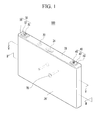
- FIG. 1 is a perspective view of a rechargeable battery according to a first exemplary embodiment of the present invention penetrated by a conductive material
- FIG. 2 is a cross-sectional view of FIG. 1 taken along the line II-II.
- the rechargeable battery 100 includes: an electrode assembly 10; a cap plate 20; a case 26; terminal portions 30 and 40 including a first terminal portion 30 and a second terminal portion 40; a current collecting member 50 including a first current collecting member 50a including a fuse portion 51 a and a second current collecting member 50b; and a lower insulating member 60 including first and second lower insulating members 60a and 60b.
- the electrode assembly 10 is formed in a jelly-roll shape by spirally winding a first electrode 11, a second electrode 12, and a separator 13 therebetween.
- the first electrode 11 may be a negative electrode and the second electrode 12 may be a positive electrode.
- first and second electrodes 11 and 12 may respectively include a current collector formed of a thin metal foil, and an active material that is coated on a surface of each current collector.
- the first and second electrodes 11 and 12 may be divided into coated regions where the active material is coated on the current collector, and a first electrode uncoated region 11 a and a second electrode uncoated region 12a that are respectively located at opposite ends of the coated regions and where the active material is not coated on the current collector.
- the electrode assembly 10 is not limited to the jelly-roll shape, and it may have a structure in which the first and second electrodes 11 and 12 formed by a plurality of sheets are layered while interposing the separator 13 therebetween.
- An opening is formed in the case 26 according to the present exemplary embodiment, and the electrode assembly 10 inserted through the opening is accommodated inside the case 26.
- the cap plate 20 according to the present exemplary embodiment is combined to the opening of the case 26 to seal the case 26.
- the cap plate 20 may include: an electrolyte injection opening 21; a sealing cap 22 for sealing the electrolyte injection opening 21; a vent plate 24 configured to be ruptured when internal pressure of the case 26 exceeds a predetermined pressure; and a vent hole 23 in which the vent plate 24 is installed.
- the terminal portions 30 and 40 include terminals 31 and 41, terminal plates 32 and 42, a connecting member 33 or terminal insulating member 43, and gaskets 34 and 44.
- the first terminal portion 30 of the terminal portions 30 and 40 may include a first terminal 31, a first terminal plate 32, the connecting member 33, and a first gasket 34.
- the first terminal 31 is installed to penetrate the cap plate 20 while being electrically coupled to the second electrode 12 of the electrode assembly 10 through the first current collecting member 50a.
- the first terminal plate 32 is combined to the first terminal 31 to be electrically coupled to the second electrode 12 of the electrode assembly 10 through the first terminal 31.
- the connecting member 33 is installed between the first terminal 31 and the cap plate 20, and includes a sinuous body 33a that electrically couples the first terminal plate 32 and the cap plate 20.
- the first gasket 34 is installed between the first terminal 31 and the cap plate 20 to electrically insulate between the first terminal 31 and the cap plate 20.
- the second terminal portion 40 of the terminal portions 30 and 40 may include a second terminal 41, a second terminal plate 42, a second terminal insulating member 43, and a second gasket 44.
- the second terminal portion 40 has the same structure as the first terminal portion 30 except for the second terminal insulating member 43.
- the second terminal insulating member 43 is installed between the second terminal plate 42 and the cap plate 20 to electrically insulate the second terminal plate 42 from the cap plate 20.
- the cap plate 20 may be electrically coupled to the second electrode 12 through the connecting member 33, and the case 26 may be electrically coupled to the second electrode 12 through the cap plate 20.
- the connecting member 33 according to the present exemplary embodiment will now be described in detail.
- FIG. 3 is a perspective view of a connecting member of the rechargeable battery of FIG. 1
- FIG. 4A is a top plan view of the connecting member of FIG. 3
- FIG. 4B is a bottom view of the connecting member of FIG. 3 .
- the connecting member 33 includes the sinuous body 33a that is installed between the cap plate 20 and the first terminal plate 32.
- the sinuous body 33a of the connecting member 33 may include a first connector 33a1, a second connector 33a2, a bent portion 33a3, and a through-hole 33a4 through which the first terminal 31 penetrates.
- the sinuous body 33a of the connecting member 33 is installed between the terminal plate 32 and the cap plate 20 such that one side faces the terminal plate 32 while the other side faces the cap plate 20.
- the first connector 33a1 is formed at one side of the sinuous body 33a that faces the terminal plate 32
- the second connector 33a2 is formed at the other side of the sinuous body 33a that faces the cap plate 20.
- the first connector 33a1 is installed to face the first terminal plate 32 such that it is electrically coupled to the first terminal plate 32.
- the second connector 33a2 is installed to face the cap plate 20 such that it is electrically coupled to the cap plate 20.
- the first and second connectors 33a1 and 33a2 may be coupled through the bent portion 33a3.
- the bent portion 33a3 has a sinuous shape, and may be formed, for example, by bending a long thin plate or winding it in a coil-like shape.
- the bent portion 33a2 may be covered with insulating coating layers 33a5 and 33a6.
- the insulating coating layers 33a5 and 33a6 may include a first insulating coating layer 33a5 and a second insulating coating layer 33a6.
- the first insulating coating layer 33a5 is coated on a portion of one side of the sinuous body 33a facing the first terminal plate 32 where the first connector 33a1 is not positioned.
- the second insulating coating layer 33a6 is coated on a portion of the other side of the sinuous body 33a facing the cap plate 20 where the second connector 33a2 is not positioned.
- the first terminal plate 32 is electrically insulated from the bent portion 33a3 by the first insulating coating layer 33a5, and the cap plate 20 is electrically insulated from the bent portion 33a3 by the second insulating coating layer 33a6.
- a current path formed by the first connector 33a1 for electrically coupling the first terminal 31 and the cap plate 20, the bent portion 33a3, and the second connector 33a2 may be formed in the connecting member 33.
- the first electrode 11 is located at an outer surface of the electrode assembly 10.
- the case 26 that is electrically coupled to the second electrode 12 through the connecting member 33 may be positively charged.
- the positively charged case 26 and the negatively charged first electrode 11 are located at opposite surfaces of the separator 13 with the separator 13 located therebetween.
- a conductive material 70 e.g., a nail
- the conductive material 70 sequentially penetrates the case 26, the separator 13, and the first and second electrodes 11 and 12, thereby generating a short-circuit current between the first electrode 11 and the second electrode 12.
- a short-circuit current path is formed between the first electrode 11 and the second electrode 12 to discharge the short-circuit current to the outside of the electrode assembly 10 by way of the conductive material 70, the cap plate 20 combined to the case 26, the connecting member 33, the first terminal plate 32, the first terminal 31, and the first current collecting member 50a.
- the short-circuit current flowing between the first and second electrodes 11 and 12 remains inside the electrode assembly 10 as long as the first and second electrodes 11 and 12 are short-circuited by the conductive material 70.
- the short-circuit current remaining inside the electrode assembly 10 may be minimized.
- the short-circuit current is effectively dissipated in the connecting member 33 that forms the short-circuit current path between the first and second electrodes 11 and 12, thereby minimizing the amount of the short-circuit current remaining inside of the electrode assembly 10.
- the short-circuit current generated by the short-circuit of the first and second electrodes 11 and 12 may be discharged from the electrode assembly 10 through the short-circuit current path, and may be dissipated through the connecting member 33 that is installed between the first terminal plate 32 and the cap plate 20.
- the short-circuit current passing through the short-circuit current path between the first and second electrodes 11 and 12 is discharged from the electrode assembly 10 to pass through the case 26, the cap plate 20, the second connector 33a2 electrically coupled to the cap plate 20, the sinuous bent portion 33a3, and the first connector 33a1 electrically coupled to the first terminal plate 32.
- the amount of the short-circuit current passing through the fuse portion 51 a of the first current collecting member 50a decreases in proportion to the amount of the short-circuit current that is dissipated in the connecting member 33.
- a melting time of the fuse portion 51 a may be delayed.
- the short-circuit current path between the first and second electrodes 11 and 12 may continue to exist further for a melting delay time of the fuse portion 51 a.
- the short-circuit current generated by the short-circuit of the first and second electrodes 11 and 12 may be discharged outside of the electrode assembly 10 through the short-circuit current path for the melting delay time of the fuse portion 51 a to be dissipated in the connecting member 33, the amount of the short-circuit current remaining inside the electrode assembly 10 after the fuse portion 51 a is melted and then the short-circuit current path ceases to exist may be minimized.
- the short-circuit current which is generated by the short-circuit of the first and second electrodes 11 and 12 due to the penetration of the conductive material 70, can be sufficiently discharged outside of the electrode assembly 10 through the short-circuit current path for the melting delay time of the fuse portion 51 a, the ignition or explosion of the electrode assembly 10 due to the short-circuit current remaining inside the electrode assembly 10 after the short-circuit current path ceases to exist can be prevented by the melting of the fuse portion 51 a.
- FIG. 6 is a perspective view of a connecting member according to a second exemplary embodiment of the present invention
- FIG. 7 is a front view of the connecting member of FIG. 6 .
- a connecting member 130 according to the present exemplary embodiment includes a sinuous body 130a that is installed between the cap plate 20 and the first terminal plate 32.
- the sinuous body 130a of the connecting member 130 may include a first connector 131, a second connector 132, a bent portion 133, and a through-hole 134 through which the first terminal 31 penetrates.
- the sinuous body 130a of the connecting member 130 is installed between the first terminal plate 32 and the cap plate 20 such that one side faces the first terminal plate 32 and the other side faces the cap plate 20.
- the first connector 131 is formed at one side of the sinuous body 130a that faces the first terminal plate 32
- the second connector 132 is formed at the other side of the sinuous body 130a that faces the cap plate 20.
- first connector 131 may include a first protrusion 131 a that protrudes from the one side of the sinuous body (33a, 130a, 230a), said one side facing the first terminal plate 32
- second connector 132 may include a second protrusion 132a that is located opposite to the one side to protrude from the other side of the sinuous body (33a, 130a, 230a), said other side facing the cap plate 20.
- the first protrusion 131 a of the first connector 131 and the first terminal plate 32 may be installed to contact each other, and the second protrusion 132a of the second connector 132 and the cap plate 20 may be installed to contact each other.
- the first and second connectors 131 and 132 may be coupled through the bent portion 133.
- the bent portion 133 has a sinuous shape, and may be formed, for example, by bending a long thin plate or winding it in a coil-like shape.
- bent portion 133 may be coated with insulating coating layers 135 and 136.
- the insulating coating layers 135 and 136 may include a first insulating coating layer 135 and a second insulating coating layer 136.
- the first insulating coating layer 135 may be coated on a portion of one side of the sinuous body 130a facing the first terminal plate 32 where the first connector 131 is not positioned.
- a thickness of first insulating coating layer 135 may be equal to or less than a height of the first protrusion 131 a of the first connector 131.
- the second insulating coating layer 136 may be coated on a portion of the other side of the sinuous body 130a facing the cap plate 20 where the second connector 132 is not positioned.
- a thickness of the second insulating coating layer 136 may be equal to or less than a height of the second protrusion 132a of the second connector 132.
- the first terminal plate 32 is electrically insulated from the bent portion 133 by the first insulating coating layer 135, and the cap plate 20 is electrically insulated from the bent portion 133 by the second insulating coating layer 136.
- the first connector 131 is electrically coupled to the first terminal plate 32 through the first protrusion 131 a
- the second connector 33a2 is electrically coupled to the cap plate 20 through the second protrusion 132a.
- the first terminal plate 32 and the cap plate 20 can be stably electrically coupled through the first and second protrusions 131 a and 132a of the connecting member 130.
- FIG. 8 is a perspective view of a connecting member according to a third exemplary embodiment of the present invention
- FIG. 9 is a bottom view of the connecting member of FIG. 8 .
- the connecting member 230 includes a sinuous body 230a that is installed between the cap plate 20 and the first terminal plate 32.
- the sinuous body 230a of the connecting member 230 may include a first connector 231, a second connector 232, a bent portion 233, and a through-hole 234 through which the first terminal 31 penetrates.
- the sinuous body 230a of the connecting member 230 is installed between the terminal plate 32 and the cap plate 20 such that one side faces the terminal plate 32 and the other side faces the cap plate 20.
- the first connector 231 is formed at one side of the sinuous body 230a that faces the terminal plate 32
- the second connector 232 is formed at the other side of the sinuous body 230a that faces the cap plate 20.
- the first connector 231 is installed to face the first terminal plate 32 such that it is electrically coupled to the first terminal plate 32.
- the second connector 232 is installed to face the cap plate 20 such that it is electrically coupled to the cap plate 20.
- the first and second connectors 231 and 232 may be coupled through the bent portion 233.
- the bent portion 233 has a sinuous shape, and may be formed, for example, by bending a long thin plate or winding it in a coil-like shape.
- bent portion 233 may be coated with insulating coating layers 235 and 236.
- the insulating coating layers 235 and 236 may include a first insulating coating layer 235 and a second insulating coating layer 236.
- the first insulating coating layer 235 is coated on a portion of one side of the sinuous body 230a facing the first terminal plate 32 where the first connector 231 is not positioned.
- the second insulating coating layer 236 is coated on a portion of the other side of the sinuous body 230a facing the cap plate 20 where the second connector 232 is not positioned.
- the first terminal plate 32 is electrically insulated from the bent portion 233 by the first insulating coating layer 235
- the cap plate 20 is electrically insulated from the bent portion 233 by the second insulating coating layer 236.
- a current path formed by the first connector 231 for electrically coupling the first terminal 32 and the cap plate 20, the bent portion 233, and the second connector 232 can be formed.
Landscapes
- Chemical & Material Sciences (AREA)
- Chemical Kinetics & Catalysis (AREA)
- Electrochemistry (AREA)
- General Chemical & Material Sciences (AREA)
- Engineering & Computer Science (AREA)
- Manufacturing & Machinery (AREA)
- Connection Of Batteries Or Terminals (AREA)
Abstract
Description
- The present invention relates to a rechargeable battery.
- A rechargeable battery differs from a primary battery in that it can be repeatedly charged and discharged, while the latter is incapable of being recharged.
- A low-capacity rechargeable battery is used in small portable electronic devices such as mobile phones, notebook computers, and camcorders, while a high-capacity rechargeable battery is widely used as a power source for driving a motor of a hybrid vehicle or a large-capacity power storage device.
- Recently, a high power rechargeable battery using a non-aqueous electrolyte and having high energy density has been developed, and the high power rechargeable battery is formed as a large-capacity battery module in which a plurality of rechargeable batteries are connected in series, such that it can be used as a power source for driving a motor of a device requiring a large amount of electric power, for example, an electric vehicle or the like.
- Such a rechargeable battery has a case that may be formed to have a cylindrical shape, a prismatic shape, etc.
- When a conductive material (e.g., a conductive nail) or the like penetrates the case and enters an electrode assembly, a negative electrode and a positive electrode forming the electrode assembly can be short-circuited.
- In this case, a temperature of the electrode assembly increases due to a short-circuit current generated inside the rechargeable battery, thereby potentially causing ignition or explosion of the electrode assembly.
- The above information disclosed in this Background section is only for enhancement of understanding of the background of the invention and therefore it may contain information that does not form the prior art that is already known in this country to a person of ordinary skill in the art.
- Embodiments of the present invention provide a rechargeable battery including a structure for preventing ignition or explosion of a rechargeable battery due to a short-circuit current generated by a short-circuit.
- A rechargeable battery according to an exemplary embodiment of the present invention includes: a case; an electrode assembly for accommodated in the case; a cap plate for sealing an opening of the case; terminals electrically coupled to the electrode assembly and installed to penetrate the cap plate; terminal plates installed on the cap plate to be coupled to the terminals; and a connecting member including a sinuous body installed between the cap plate and the terminal plate to electrically couple the cap plate and the terminal plate.
- The sinuous body may include a first connector that is installed to face the terminal plate to be electrically coupled to the terminal plate, a second connector that is installed to face the cap plate to be electrically coupled to the cap plate, and a bent portion that connects the first connector and the second connector.
- The bent portion of the sinuous body may be covered with an insulating coating layer.
- The bent portion of the sinuous body may be spiral-shaped.
- The first connector may include a first protrusion that protrudes from one side of the sinuous body, the one side facing the terminal plate, and the second connector may include a second protrusion that is disposed opposite to the one side to protrude from the other side of the sinuous body, the other side facing the cap plate.
- One side on which the first protrusion of the bent portion is formed may be covered with a first insulating coating layer that has a smaller thickness than a height of the first protrusion, and the other side on which the second protrusion of the bent portion is formed may be covered with a second insulating coating layer that has a smaller thickness than a height of the second protrusion.
- The sinuous body of the connecting member may include a through-hole through which the terminal penetrates.
- The rechargeable battery may further include a current collecting member electrically coupling the terminal and the electrode assembly and including a fuse portion.
- According to exemplary embodiments of the present invention, the short-circuit current generated by the short-circuit can be dissipated outside of the electrode assembly, thereby preventing ignition or explosion of the rechargeable battery due to the short-circuit current.
-
-
FIG. 1 is a perspective view of a rechargeable battery according to a first exemplary embodiment of the present invention penetrated by a conductive material. -
FIG. 2 is a cross-sectional view ofFIG. 1 taken along the line II-II. -
FIG. 3 is a perspective view of a connecting member of the rechargeable battery ofFIG. 1 . -
FIG. 4A is a top plan view of the connecting member ofFIG. 3 . -
FIG. 4B is a bottom view of the connecting member ofFIG. 3 . -
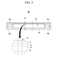
FIG. 5 is a cross-sectional view ofFIG. 1 taken along the line V-V. -
FIG. 6 is a perspective view of a connecting member according to a second exemplary embodiment of the present invention. -
FIG. 7 is a front view of the connecting member ofFIG. 6 . -
FIG. 8 is a perspective view of a connecting member according to a third exemplary embodiment of the present invention. -
FIG. 9 is a bottom view of the connecting member ofFIG. 8 . - The present invention will be described more fully hereinafter with reference to the accompanying drawings, in which exemplary embodiments of the invention are shown.
- As those skilled in the art would realize, the described embodiments may be modified in various different ways, all without departing from the scope of the present invention as set forth in the claims.
- In the drawings, the dimensions of layers or regions may be exaggerated for clarity of description.
- It will be understood that when a layer or element is referred to as being "on" another layer or substrate, this not only discloses an embodiment where the layer or element is directly on the other layer or element but also discloses further embodiments where intervening layers or elements are present.
- In addition, it will be understood that when a layer is referred to as being "under" another layer, this not only discloses an embodiment where the layer or element is directly under the other layer but also discloses further embodiments where one or more intervening layers are present.
- Moreover, it will be understood that when a layer is referred to as being "between" two layers, this not only discloses an embodiment where the layer is the only one layer between the two layers but also discloses further embodiments where one or more intervening layers are present.
- In the present specification and the drawings, like reference numerals designate like elements throughout the specification.
-
FIG. 1 is a perspective view of a rechargeable battery according to a first exemplary embodiment of the present invention penetrated by a conductive material, andFIG. 2 is a cross-sectional view ofFIG. 1 taken along the line II-II. - Referring to
FIGS. 1 and2 , therechargeable battery 100 according to the present exemplary embodiment includes: anelectrode assembly 10; acap plate 20; acase 26;terminal portions first terminal portion 30 and asecond terminal portion 40; acurrent collecting member 50 including a firstcurrent collecting member 50a including afuse portion 51 a and a secondcurrent collecting member 50b; and a lowerinsulating member 60 including first and secondlower insulating members - The
electrode assembly 10 according to the present exemplary embodiment is formed in a jelly-roll shape by spirally winding afirst electrode 11, asecond electrode 12, and aseparator 13 therebetween. - In this case, the
first electrode 11 may be a negative electrode and thesecond electrode 12 may be a positive electrode. - In addition, the first and
second electrodes - Specifically, the first and
second electrodes region 11 a and a second electrodeuncoated region 12a that are respectively located at opposite ends of the coated regions and where the active material is not coated on the current collector. - However, the
electrode assembly 10 according to the present exemplary embodiment is not limited to the jelly-roll shape, and it may have a structure in which the first andsecond electrodes separator 13 therebetween. - An opening is formed in the
case 26 according to the present exemplary embodiment, and theelectrode assembly 10 inserted through the opening is accommodated inside thecase 26. - The
cap plate 20 according to the present exemplary embodiment is combined to the opening of thecase 26 to seal thecase 26. - In addition, the
cap plate 20 may include: an electrolyte injection opening 21; asealing cap 22 for sealing the electrolyte injection opening 21; avent plate 24 configured to be ruptured when internal pressure of thecase 26 exceeds a predetermined pressure; and avent hole 23 in which thevent plate 24 is installed. - The
terminal portions terminals terminal plates member 33 orterminal insulating member 43, andgaskets - Specifically, the
first terminal portion 30 of theterminal portions first terminal 31, afirst terminal plate 32, the connectingmember 33, and afirst gasket 34. - The
first terminal 31 is installed to penetrate thecap plate 20 while being electrically coupled to thesecond electrode 12 of theelectrode assembly 10 through the firstcurrent collecting member 50a. - The
first terminal plate 32 is combined to thefirst terminal 31 to be electrically coupled to thesecond electrode 12 of theelectrode assembly 10 through thefirst terminal 31. - The connecting
member 33 is installed between thefirst terminal 31 and thecap plate 20, and includes asinuous body 33a that electrically couples thefirst terminal plate 32 and thecap plate 20. - The
first gasket 34 is installed between thefirst terminal 31 and thecap plate 20 to electrically insulate between thefirst terminal 31 and thecap plate 20. - The
second terminal portion 40 of theterminal portions second terminal 41, asecond terminal plate 42, a secondterminal insulating member 43, and asecond gasket 44. - The
second terminal portion 40 has the same structure as thefirst terminal portion 30 except for the secondterminal insulating member 43. - In one embodiment, the second
terminal insulating member 43 according to the present exemplary embodiment is installed between thesecond terminal plate 42 and thecap plate 20 to electrically insulate thesecond terminal plate 42 from thecap plate 20. - Thus, according to the present exemplary embodiment, the
cap plate 20 may be electrically coupled to thesecond electrode 12 through the connectingmember 33, and thecase 26 may be electrically coupled to thesecond electrode 12 through thecap plate 20. - The connecting
member 33 according to the present exemplary embodiment will now be described in detail. -
FIG. 3 is a perspective view of a connecting member of the rechargeable battery ofFIG. 1 ,FIG. 4A is a top plan view of the connecting member ofFIG. 3 , andFIG. 4B is a bottom view of the connecting member ofFIG. 3 . - Referring to
FIGS. 3 to 4B , the connectingmember 33 according to the present exemplary embodiment includes thesinuous body 33a that is installed between thecap plate 20 and the firstterminal plate 32. - In this case, the
sinuous body 33a of the connectingmember 33 may include a first connector 33a1, a second connector 33a2, a bent portion 33a3, and a through-hole 33a4 through which thefirst terminal 31 penetrates. - In addition, the
sinuous body 33a of the connectingmember 33 is installed between theterminal plate 32 and thecap plate 20 such that one side faces theterminal plate 32 while the other side faces thecap plate 20. - According to the present exemplary embodiment, the first connector 33a1 is formed at one side of the
sinuous body 33a that faces theterminal plate 32, and the second connector 33a2 is formed at the other side of thesinuous body 33a that faces thecap plate 20. - Accordingly, the first connector 33a1 is installed to face the first
terminal plate 32 such that it is electrically coupled to the firstterminal plate 32. - The second connector 33a2 is installed to face the
cap plate 20 such that it is electrically coupled to thecap plate 20. - The first and second connectors 33a1 and 33a2 may be coupled through the bent portion 33a3.
- The bent portion 33a3 has a sinuous shape, and may be formed, for example, by bending a long thin plate or winding it in a coil-like shape.
- The bent portion 33a2 may be covered with insulating coating layers 33a5 and 33a6.
- The insulating coating layers 33a5 and 33a6 may include a first insulating coating layer 33a5 and a second insulating coating layer 33a6.
- Specifically, the first insulating coating layer 33a5 is coated on a portion of one side of the
sinuous body 33a facing the firstterminal plate 32 where the first connector 33a1 is not positioned. - The second insulating coating layer 33a6 is coated on a portion of the other side of the
sinuous body 33a facing thecap plate 20 where the second connector 33a2 is not positioned. - In one embodiment, the first
terminal plate 32 is electrically insulated from the bent portion 33a3 by the first insulating coating layer 33a5, and thecap plate 20 is electrically insulated from the bent portion 33a3 by the second insulating coating layer 33a6. - Accordingly, based on the present exemplary embodiment, a current path formed by the first connector 33a1 for electrically coupling the
first terminal 31 and thecap plate 20, the bent portion 33a3, and the second connector 33a2 may be formed in the connectingmember 33. - Referring to
FIG. 2 , thefirst electrode 11 according to the present exemplary embodiment is located at an outer surface of theelectrode assembly 10. - In one embodiment, since the
first electrode 11 may be the negative electrode and thesecond electrode 12 may be the positive electrode, thecase 26 that is electrically coupled to thesecond electrode 12 through the connectingmember 33 may be positively charged. - The positively charged
case 26 and the negatively chargedfirst electrode 11 are located at opposite surfaces of theseparator 13 with theseparator 13 located therebetween. - Accordingly, when a conductive material 70 (e.g., a nail) penetrates the
rechargeable battery 100, theconductive material 70 sequentially penetrates thecase 26, theseparator 13, and the first andsecond electrodes first electrode 11 and thesecond electrode 12. - In this case, a short-circuit current path is formed between the
first electrode 11 and thesecond electrode 12 to discharge the short-circuit current to the outside of theelectrode assembly 10 by way of theconductive material 70, thecap plate 20 combined to thecase 26, the connectingmember 33, the firstterminal plate 32, thefirst terminal 31, and the first current collectingmember 50a. - Even if the short-circuit current path formed between the
first electrode 11 and thesecond electrode 12 ceases to exist, the short-circuit current flowing between the first andsecond electrodes electrode assembly 10 as long as the first andsecond electrodes conductive material 70. - Accordingly, in order to prevent ignition or explosion of the
electrode assembly 10 due to the short-circuit current remaining inside theelectrode assembly 10, the short-circuit current remaining inside theelectrode assembly 10 may be minimized. - According to the present exemplary embodiment, the short-circuit current is effectively dissipated in the connecting
member 33 that forms the short-circuit current path between the first andsecond electrodes electrode assembly 10. - Specifically, according to the present exemplary embodiment, the short-circuit current generated by the short-circuit of the first and
second electrodes electrode assembly 10 through the short-circuit current path, and may be dissipated through the connectingmember 33 that is installed between the firstterminal plate 32 and thecap plate 20. - In other words, the short-circuit current passing through the short-circuit current path between the first and
second electrodes electrode assembly 10 to pass through thecase 26, thecap plate 20, the second connector 33a2 electrically coupled to thecap plate 20, the sinuous bent portion 33a3, and the first connector 33a1 electrically coupled to the firstterminal plate 32. - In this case, some of the short-circuit current passing through the short-circuit current path between the first and
second electrodes member 33, the sinuous bent portion 33a3, and the first connector 33a1. - Among the short-circuit current passing through the short-circuit current path between the first and
second electrodes fuse portion 51 a of the first current collectingmember 50a decreases in proportion to the amount of the short-circuit current that is dissipated in the connectingmember 33. - Accordingly, based on the present exemplary embodiment, since the amount of the short-circuit current passing through the
fuse portion 51 a per unit time decreases due to the dissipation of the short-circuit current in the connectingmember 33, a melting time of thefuse portion 51 a may be delayed. - When the melting time of the
fuse portion 51 a is delayed as in the present exemplary embodiment, the short-circuit current path between the first andsecond electrodes fuse portion 51 a. - According to the present exemplary embodiment, since the short-circuit current generated by the short-circuit of the first and
second electrodes electrode assembly 10 through the short-circuit current path for the melting delay time of thefuse portion 51 a to be dissipated in the connectingmember 33, the amount of the short-circuit current remaining inside theelectrode assembly 10 after thefuse portion 51 a is melted and then the short-circuit current path ceases to exist may be minimized. - As a result, according to the present exemplary embodiment, since the short-circuit current, which is generated by the short-circuit of the first and
second electrodes conductive material 70, can be sufficiently discharged outside of theelectrode assembly 10 through the short-circuit current path for the melting delay time of thefuse portion 51 a, the ignition or explosion of theelectrode assembly 10 due to the short-circuit current remaining inside theelectrode assembly 10 after the short-circuit current path ceases to exist can be prevented by the melting of thefuse portion 51 a. -
FIG. 6 is a perspective view of a connecting member according to a second exemplary embodiment of the present invention, andFIG. 7 is a front view of the connecting member ofFIG. 6 . - A connecting
member 130 according to the present exemplary embodiment includes asinuous body 130a that is installed between thecap plate 20 and the firstterminal plate 32. - In this case, the
sinuous body 130a of the connectingmember 130 may include afirst connector 131, asecond connector 132, abent portion 133, and a through-hole 134 through which thefirst terminal 31 penetrates. - The
sinuous body 130a of the connectingmember 130 is installed between the firstterminal plate 32 and thecap plate 20 such that one side faces the firstterminal plate 32 and the other side faces thecap plate 20. - According to the present exemplary embodiment, the
first connector 131 is formed at one side of thesinuous body 130a that faces the firstterminal plate 32, and thesecond connector 132 is formed at the other side of thesinuous body 130a that faces thecap plate 20. - In addition, the
first connector 131 may include afirst protrusion 131 a that protrudes from the one side of the sinuous body (33a, 130a, 230a), said one side facing the firstterminal plate 32, and thesecond connector 132 may include asecond protrusion 132a that is located opposite to the one side to protrude from the other side of the sinuous body (33a, 130a, 230a), said other side facing thecap plate 20. - According to the present exemplary embodiment, the
first protrusion 131 a of thefirst connector 131 and the firstterminal plate 32 may be installed to contact each other, and thesecond protrusion 132a of thesecond connector 132 and thecap plate 20 may be installed to contact each other. - The first and
second connectors bent portion 133. - In this case, the
bent portion 133 has a sinuous shape, and may be formed, for example, by bending a long thin plate or winding it in a coil-like shape. - Further, the
bent portion 133 may be coated with insulating coating layers 135 and 136. - The insulating coating layers 135 and 136 may include a first insulating
coating layer 135 and a second insulatingcoating layer 136. - Specifically, the first insulating
coating layer 135 may be coated on a portion of one side of thesinuous body 130a facing the firstterminal plate 32 where thefirst connector 131 is not positioned. - In this case, a thickness of first insulating
coating layer 135 may be equal to or less than a height of thefirst protrusion 131 a of thefirst connector 131. - The second
insulating coating layer 136 may be coated on a portion of the other side of thesinuous body 130a facing thecap plate 20 where thesecond connector 132 is not positioned. - In this case, a thickness of the second insulating
coating layer 136 may be equal to or less than a height of thesecond protrusion 132a of thesecond connector 132. - Thus, the first
terminal plate 32 is electrically insulated from thebent portion 133 by the first insulatingcoating layer 135, and thecap plate 20 is electrically insulated from thebent portion 133 by the second insulatingcoating layer 136. - The
first connector 131 is electrically coupled to the firstterminal plate 32 through thefirst protrusion 131 a, and the second connector 33a2 is electrically coupled to thecap plate 20 through thesecond protrusion 132a. - Accordingly, according to the present exemplary embodiment, the first
terminal plate 32 and thecap plate 20 can be stably electrically coupled through the first andsecond protrusions member 130. -
FIG. 8 is a perspective view of a connecting member according to a third exemplary embodiment of the present invention, andFIG. 9 is a bottom view of the connecting member ofFIG. 8 . - Referring to
FIGS. 8 and9 , the connectingmember 230 according to the present exemplary embodiment includes asinuous body 230a that is installed between thecap plate 20 and the firstterminal plate 32. - In this case, the
sinuous body 230a of the connectingmember 230 may include afirst connector 231, asecond connector 232, abent portion 233, and a through-hole 234 through which thefirst terminal 31 penetrates. - The
sinuous body 230a of the connectingmember 230 is installed between theterminal plate 32 and thecap plate 20 such that one side faces theterminal plate 32 and the other side faces thecap plate 20. - According to the present exemplary embodiment, the
first connector 231 is formed at one side of thesinuous body 230a that faces theterminal plate 32, and thesecond connector 232 is formed at the other side of thesinuous body 230a that faces thecap plate 20. - Thus, the
first connector 231 is installed to face the firstterminal plate 32 such that it is electrically coupled to the firstterminal plate 32. - The
second connector 232 is installed to face thecap plate 20 such that it is electrically coupled to thecap plate 20. - The first and
second connectors bent portion 233. - In this case, the
bent portion 233 has a sinuous shape, and may be formed, for example, by bending a long thin plate or winding it in a coil-like shape. - Further, the
bent portion 233 may be coated with insulating coating layers 235 and 236. - The insulating coating layers 235 and 236 may include a first insulating
coating layer 235 and a second insulatingcoating layer 236. - Specifically, the first insulating
coating layer 235 is coated on a portion of one side of thesinuous body 230a facing the firstterminal plate 32 where thefirst connector 231 is not positioned. - The second
insulating coating layer 236 is coated on a portion of the other side of thesinuous body 230a facing thecap plate 20 where thesecond connector 232 is not positioned. - In this case, the first
terminal plate 32 is electrically insulated from thebent portion 233 by the first insulatingcoating layer 235, and thecap plate 20 is electrically insulated from thebent portion 233 by the second insulatingcoating layer 236. - Accordingly, based on the present exemplary embodiment, a current path formed by the
first connector 231 for electrically coupling thefirst terminal 32 and thecap plate 20, thebent portion 233, and thesecond connector 232 can be formed. - While this invention has been described in connection with what is presently considered to be practical exemplary embodiments, it is to be understood that the invention is not limited to the disclosed embodiments, but, on the contrary, is intended to cover various modifications and equivalent arrangements included within the scope of the appended claims
Description of Symbols 100: rechargeable battery 10: electrode assembly 20: cap plate 26: case 11: first electrode 12: second electrode 13: separator 30, 230: first terminal portion 31, 231: first terminal 32: first terminal plate 33, 130, 230: connecting member 33a, 130a, 230a: sinuous body 33a1, 131, 231: first connector 33a2, 132, 232: second connector 33a3, 133, 233: bent portion 33a4, 134, 234: through-hole 33a5, 135, 235: first insulating coating layer 33a6, 136, 236: second insulating coating layer 34: first gasket 40: second terminal portion 41: second terminal 42: second terminal plate 43: second terminal insulating member 44: second gasket 50: current collecting member 50a: first current collecting member 50b: second current collecting member 60: lower insulating member 60a: first lower insulating member 60b: second lower insulating member 70: conductive material 131a: first protrusion 132a: second protrusion 51a: fuse portion
Claims (8)
- A rechargeable battery (100) comprising:a case (26);an electrode assembly (10) accommodated in the case (26);a cap plate (20) sealing an opening of the case (26);terminals (31, 41, 231) electrically coupled to the electrode assembly (10) and penetrating the cap plate (20);terminal plates (32, 42) on the cap plate (20), wherein each of the terminal plates (32, 42) is coupled to a respective one of the terminals (31, 41, 231); anda connecting member (33, 130, 230) including a sinuous body (33a, 130a, 230a) located between the cap plate (20) and the terminal plate (32, 42) to electrically couple the cap plate (20) and the terminal plate (32, 42).
- The rechargeable battery of claim 1, wherein the sinuous body (33a, 130a, 230a) includes a first connector (33a1, 131, 231) that faces the terminal plate (32, 42) and is electrically coupled to the terminal plate (32, 42), a second connector (33a2, 132, 232) that faces the cap plate (20) and is electrically coupled to the cap plate (20), and a bent portion (33a3, 133, 233) that connects the first connector (33a1, 131, 231) and the second connector (33a2, 132, 232).
- The rechargeable battery of claim 2, wherein the bent portion (33a3, 133, 23) of the sinuous body (33a, 130a, 230a) is covered with an insulating coating layer (33a5, 135, 235, 33a6, 136, 236).
- The rechargeable battery of claim 2 or 3, wherein the bent portion (33a3, 133, 233) of the sinuous body (33a, 130a, 230a) is spiral-shaped.
- The rechargeable battery of one of claims 2, 3 and 4, wherein the first connector (131) includes a first protrusion (131 a) that protrudes from a first side of the sinuous body (33a, 130a, 230a), the first side facing the terminal plate (32, 42), and the second connector (132) includes a second protrusion (132a) that is located opposite to the first side to protrude from a second side of the sinuous body (33a, 130a, 230a), the second side facing the cap plate (20).
- The rechargeable battery of claim 5, wherein the first side has a first insulating coating layer (135) that is thinner than the first protrusion (131 a), and the second side is covered with a second insulating coating layer (136) that is thinner than the second protrusion (132a).
- The rechargeable battery of claim 6, further comprising a current collecting member (50) electrically coupling the terminal (31, 41, 231) and the electrode assembly (10) and including a fuse portion (51 a).
- The rechargeable battery of one of the preceding claims, wherein the sinuous body (33a, 130a, 230a) of the connecting member (33, 130, 230) includes a through-hole (33a4, 134, 234) through which the terminal (31, 41, 231) penetrates.
Applications Claiming Priority (1)
| Application Number | Priority Date | Filing Date | Title |
|---|---|---|---|
| KR1020140130394A KR102282244B1 (en) | 2014-09-29 | 2014-09-29 | Rechargeable battery |
Publications (2)
| Publication Number | Publication Date |
|---|---|
| EP3001481A1 true EP3001481A1 (en) | 2016-03-30 |
| EP3001481B1 EP3001481B1 (en) | 2017-03-29 |
Family
ID=53886848
Family Applications (1)
| Application Number | Title | Priority Date | Filing Date |
|---|---|---|---|
| EP15178663.9A Active EP3001481B1 (en) | 2014-09-29 | 2015-07-28 | Rechargeable battery |
Country Status (4)
| Country | Link |
|---|---|
| US (1) | US9825277B2 (en) |
| EP (1) | EP3001481B1 (en) |
| KR (1) | KR102282244B1 (en) |
| CN (1) | CN105470549B (en) |
Families Citing this family (1)
| Publication number | Priority date | Publication date | Assignee | Title |
|---|---|---|---|---|
| KR20180126934A (en) * | 2017-05-19 | 2018-11-28 | 삼성에스디아이 주식회사 | Secondary Battery |
Citations (6)
| Publication number | Priority date | Publication date | Assignee | Title |
|---|---|---|---|---|
| US20110177387A1 (en) * | 2010-01-15 | 2011-07-21 | Sang-Won Byun | Rechargeable battery |
| EP2461393A1 (en) * | 2010-12-02 | 2012-06-06 | SB LiMotive Co., Ltd. | Rechargeable Battery |
| EP2551938A1 (en) * | 2011-07-28 | 2013-01-30 | SB LiMotive Co., Ltd. | Connection between a terminal and a cap plate of a rechargeable battery |
| EP2660896A1 (en) * | 2012-05-04 | 2013-11-06 | Samsung SDI Co., Ltd. | Rechargeable battery |
| EP2757614A1 (en) * | 2013-01-18 | 2014-07-23 | Samsung SDI Co., Ltd. | Secondary battery and assembling method thereof |
| EP2860786A1 (en) * | 2013-10-08 | 2015-04-15 | Samsung SDI Co., Ltd. | Case for secondary battery |
Family Cites Families (8)
| Publication number | Priority date | Publication date | Assignee | Title |
|---|---|---|---|---|
| US6120928A (en) * | 1994-07-07 | 2000-09-19 | Alps Electric Co., Ltd. | Protection device and battery cell using this protection device |
| JP2005108583A (en) | 2003-09-30 | 2005-04-21 | Fdk Energy Co Ltd | Battery |
| JP5105394B2 (en) | 2006-03-15 | 2012-12-26 | 日立ビークルエナジー株式会社 | Battery unit |
| EP2347461B1 (en) * | 2008-11-21 | 2016-04-06 | Johnson Controls Saft Advanced Power Solutions LLC | Current collector for an electrochemical cell |
| JP5764911B2 (en) | 2010-11-01 | 2015-08-19 | ソニー株式会社 | Battery pack and power consuming equipment |
| KR20130040576A (en) | 2011-10-14 | 2013-04-24 | 삼성에스디아이 주식회사 | Rechargeable battery |
| KR101887942B1 (en) | 2012-05-07 | 2018-08-14 | 삼성전자주식회사 | Light emitting device |
| CN202839773U (en) * | 2012-08-23 | 2013-03-27 | 宁德时代新能源科技有限公司 | Power battery safety top cap |
-
2014
- 2014-09-29 KR KR1020140130394A patent/KR102282244B1/en active Active
-
2015
- 2015-06-02 US US14/728,942 patent/US9825277B2/en active Active
- 2015-07-28 EP EP15178663.9A patent/EP3001481B1/en active Active
- 2015-08-20 CN CN201510515382.6A patent/CN105470549B/en active Active
Patent Citations (6)
| Publication number | Priority date | Publication date | Assignee | Title |
|---|---|---|---|---|
| US20110177387A1 (en) * | 2010-01-15 | 2011-07-21 | Sang-Won Byun | Rechargeable battery |
| EP2461393A1 (en) * | 2010-12-02 | 2012-06-06 | SB LiMotive Co., Ltd. | Rechargeable Battery |
| EP2551938A1 (en) * | 2011-07-28 | 2013-01-30 | SB LiMotive Co., Ltd. | Connection between a terminal and a cap plate of a rechargeable battery |
| EP2660896A1 (en) * | 2012-05-04 | 2013-11-06 | Samsung SDI Co., Ltd. | Rechargeable battery |
| EP2757614A1 (en) * | 2013-01-18 | 2014-07-23 | Samsung SDI Co., Ltd. | Secondary battery and assembling method thereof |
| EP2860786A1 (en) * | 2013-10-08 | 2015-04-15 | Samsung SDI Co., Ltd. | Case for secondary battery |
Also Published As
| Publication number | Publication date |
|---|---|
| KR20160038176A (en) | 2016-04-07 |
| KR102282244B1 (en) | 2021-07-28 |
| US9825277B2 (en) | 2017-11-21 |
| CN105470549B (en) | 2019-09-06 |
| EP3001481B1 (en) | 2017-03-29 |
| US20160093867A1 (en) | 2016-03-31 |
| CN105470549A (en) | 2016-04-06 |
Similar Documents
| Publication | Publication Date | Title |
|---|---|---|
| KR102335021B1 (en) | Rechargeable battery and module of the same | |
| KR101244738B1 (en) | Rechargeable battery having resistance member | |
| KR101155889B1 (en) | Rechargeable battery | |
| US10535846B2 (en) | Secondary battery | |
| US10033026B2 (en) | Rechargeable battery having an external terminal and module thereof | |
| EP2642561B1 (en) | Rechargeable battery | |
| CN103943809B (en) | Secondary cell | |
| US20120052341A1 (en) | Rechargeable battery | |
| US9660249B2 (en) | Rechargeable battery having a fuse | |
| US9627677B2 (en) | Rechargeable battery | |
| CN102088106B (en) | rechargeable battery | |
| EP2849263B1 (en) | Rechargeable battery | |
| US9093723B2 (en) | Rechargeable battery | |
| CN106356490A (en) | Rechargeable battery and rechargeable battery module using the same | |
| KR20260002386A (en) | Secondary Battery | |
| US9991500B2 (en) | Rechargeable battery | |
| US9065130B2 (en) | Rechargeable battery | |
| US8877371B2 (en) | Rechargeable battery | |
| US8450002B2 (en) | Electrode assembly including electrode having non-coated portion, method of manufacturing the same, and secondary battery including the same | |
| US20130095373A1 (en) | Rechargeable battery | |
| CN105938891B (en) | Rechargeable battery with connecting member | |
| US9397329B2 (en) | Rechargeable battery having lead tab | |
| EP3001481B1 (en) | Rechargeable battery | |
| EP2330660B1 (en) | Rechargeable battery | |
| KR100936259B1 (en) | Secondary battery pack with excellent manufacturing processability and structural stability |
Legal Events
| Date | Code | Title | Description |
|---|---|---|---|
| PUAI | Public reference made under article 153(3) epc to a published international application that has entered the european phase |
Free format text: ORIGINAL CODE: 0009012 |
|
| AK | Designated contracting states |
Kind code of ref document: A1 Designated state(s): AL AT BE BG CH CY CZ DE DK EE ES FI FR GB GR HR HU IE IS IT LI LT LU LV MC MK MT NL NO PL PT RO RS SE SI SK SM TR |
|
| AX | Request for extension of the european patent |
Extension state: BA ME |
|
| 17P | Request for examination filed |
Effective date: 20160927 |
|
| RBV | Designated contracting states (corrected) |
Designated state(s): AL AT BE BG CH CY CZ DE DK EE ES FI FR GB GR HR HU IE IS IT LI LT LU LV MC MK MT NL NO PL PT RO RS SE SI SK SM TR |
|
| GRAP | Despatch of communication of intention to grant a patent |
Free format text: ORIGINAL CODE: EPIDOSNIGR1 |
|
| STAA | Information on the status of an ep patent application or granted ep patent |
Free format text: STATUS: GRANT OF PATENT IS INTENDED |
|
| RIC1 | Information provided on ipc code assigned before grant |
Ipc: H01M 2/04 20060101ALI20161117BHEP Ipc: H01M 2/02 20060101AFI20161117BHEP Ipc: H01M 2/26 20060101ALI20161117BHEP Ipc: H01M 2/30 20060101ALI20161117BHEP Ipc: H01M 2/34 20060101ALI20161117BHEP |
|
| INTG | Intention to grant announced |
Effective date: 20161208 |
|
| GRAS | Grant fee paid |
Free format text: ORIGINAL CODE: EPIDOSNIGR3 |
|
| GRAA | (expected) grant |
Free format text: ORIGINAL CODE: 0009210 |
|
| STAA | Information on the status of an ep patent application or granted ep patent |
Free format text: STATUS: THE PATENT HAS BEEN GRANTED |
|
| AK | Designated contracting states |
Kind code of ref document: B1 Designated state(s): AL AT BE BG CH CY CZ DE DK EE ES FI FR GB GR HR HU IE IS IT LI LT LU LV MC MK MT NL NO PL PT RO RS SE SI SK SM TR |
|
| REG | Reference to a national code |
Ref country code: GB Ref legal event code: FG4D |
|
| REG | Reference to a national code |
Ref country code: CH Ref legal event code: EP |
|
| REG | Reference to a national code |
Ref country code: AT Ref legal event code: REF Ref document number: 880508 Country of ref document: AT Kind code of ref document: T Effective date: 20170415 |
|
| REG | Reference to a national code |
Ref country code: IE Ref legal event code: FG4D |
|
| REG | Reference to a national code |
Ref country code: DE Ref legal event code: R096 Ref document number: 602015001997 Country of ref document: DE |
|
| REG | Reference to a national code |
Ref country code: FR Ref legal event code: PLFP Year of fee payment: 3 |
|
| PG25 | Lapsed in a contracting state [announced via postgrant information from national office to epo] |
Ref country code: FI Free format text: LAPSE BECAUSE OF FAILURE TO SUBMIT A TRANSLATION OF THE DESCRIPTION OR TO PAY THE FEE WITHIN THE PRESCRIBED TIME-LIMIT Effective date: 20170329 Ref country code: NO Free format text: LAPSE BECAUSE OF FAILURE TO SUBMIT A TRANSLATION OF THE DESCRIPTION OR TO PAY THE FEE WITHIN THE PRESCRIBED TIME-LIMIT Effective date: 20170629 Ref country code: LT Free format text: LAPSE BECAUSE OF FAILURE TO SUBMIT A TRANSLATION OF THE DESCRIPTION OR TO PAY THE FEE WITHIN THE PRESCRIBED TIME-LIMIT Effective date: 20170329 Ref country code: GR Free format text: LAPSE BECAUSE OF FAILURE TO SUBMIT A TRANSLATION OF THE DESCRIPTION OR TO PAY THE FEE WITHIN THE PRESCRIBED TIME-LIMIT Effective date: 20170630 Ref country code: HR Free format text: LAPSE BECAUSE OF FAILURE TO SUBMIT A TRANSLATION OF THE DESCRIPTION OR TO PAY THE FEE WITHIN THE PRESCRIBED TIME-LIMIT Effective date: 20170329 |
|
| REG | Reference to a national code |
Ref country code: NL Ref legal event code: MP Effective date: 20170329 |
|
| REG | Reference to a national code |
Ref country code: AT Ref legal event code: MK05 Ref document number: 880508 Country of ref document: AT Kind code of ref document: T Effective date: 20170329 |
|
| PG25 | Lapsed in a contracting state [announced via postgrant information from national office to epo] |
Ref country code: LV Free format text: LAPSE BECAUSE OF FAILURE TO SUBMIT A TRANSLATION OF THE DESCRIPTION OR TO PAY THE FEE WITHIN THE PRESCRIBED TIME-LIMIT Effective date: 20170329 Ref country code: BG Free format text: LAPSE BECAUSE OF FAILURE TO SUBMIT A TRANSLATION OF THE DESCRIPTION OR TO PAY THE FEE WITHIN THE PRESCRIBED TIME-LIMIT Effective date: 20170629 Ref country code: RS Free format text: LAPSE BECAUSE OF FAILURE TO SUBMIT A TRANSLATION OF THE DESCRIPTION OR TO PAY THE FEE WITHIN THE PRESCRIBED TIME-LIMIT Effective date: 20170329 Ref country code: SE Free format text: LAPSE BECAUSE OF FAILURE TO SUBMIT A TRANSLATION OF THE DESCRIPTION OR TO PAY THE FEE WITHIN THE PRESCRIBED TIME-LIMIT Effective date: 20170329 |
|
| PG25 | Lapsed in a contracting state [announced via postgrant information from national office to epo] |
Ref country code: NL Free format text: LAPSE BECAUSE OF FAILURE TO SUBMIT A TRANSLATION OF THE DESCRIPTION OR TO PAY THE FEE WITHIN THE PRESCRIBED TIME-LIMIT Effective date: 20170329 |
|
| PG25 | Lapsed in a contracting state [announced via postgrant information from national office to epo] |
Ref country code: IT Free format text: LAPSE BECAUSE OF FAILURE TO SUBMIT A TRANSLATION OF THE DESCRIPTION OR TO PAY THE FEE WITHIN THE PRESCRIBED TIME-LIMIT Effective date: 20170329 Ref country code: CZ Free format text: LAPSE BECAUSE OF FAILURE TO SUBMIT A TRANSLATION OF THE DESCRIPTION OR TO PAY THE FEE WITHIN THE PRESCRIBED TIME-LIMIT Effective date: 20170329 Ref country code: AT Free format text: LAPSE BECAUSE OF FAILURE TO SUBMIT A TRANSLATION OF THE DESCRIPTION OR TO PAY THE FEE WITHIN THE PRESCRIBED TIME-LIMIT Effective date: 20170329 Ref country code: EE Free format text: LAPSE BECAUSE OF FAILURE TO SUBMIT A TRANSLATION OF THE DESCRIPTION OR TO PAY THE FEE WITHIN THE PRESCRIBED TIME-LIMIT Effective date: 20170329 Ref country code: RO Free format text: LAPSE BECAUSE OF FAILURE TO SUBMIT A TRANSLATION OF THE DESCRIPTION OR TO PAY THE FEE WITHIN THE PRESCRIBED TIME-LIMIT Effective date: 20170329 Ref country code: SK Free format text: LAPSE BECAUSE OF FAILURE TO SUBMIT A TRANSLATION OF THE DESCRIPTION OR TO PAY THE FEE WITHIN THE PRESCRIBED TIME-LIMIT Effective date: 20170329 Ref country code: ES Free format text: LAPSE BECAUSE OF FAILURE TO SUBMIT A TRANSLATION OF THE DESCRIPTION OR TO PAY THE FEE WITHIN THE PRESCRIBED TIME-LIMIT Effective date: 20170329 |
|
| PG25 | Lapsed in a contracting state [announced via postgrant information from national office to epo] |
Ref country code: IS Free format text: LAPSE BECAUSE OF FAILURE TO SUBMIT A TRANSLATION OF THE DESCRIPTION OR TO PAY THE FEE WITHIN THE PRESCRIBED TIME-LIMIT Effective date: 20170729 Ref country code: PL Free format text: LAPSE BECAUSE OF FAILURE TO SUBMIT A TRANSLATION OF THE DESCRIPTION OR TO PAY THE FEE WITHIN THE PRESCRIBED TIME-LIMIT Effective date: 20170329 Ref country code: SM Free format text: LAPSE BECAUSE OF FAILURE TO SUBMIT A TRANSLATION OF THE DESCRIPTION OR TO PAY THE FEE WITHIN THE PRESCRIBED TIME-LIMIT Effective date: 20170329 |
|
| REG | Reference to a national code |
Ref country code: DE Ref legal event code: R097 Ref document number: 602015001997 Country of ref document: DE |
|
| PG25 | Lapsed in a contracting state [announced via postgrant information from national office to epo] |
Ref country code: DK Free format text: LAPSE BECAUSE OF FAILURE TO SUBMIT A TRANSLATION OF THE DESCRIPTION OR TO PAY THE FEE WITHIN THE PRESCRIBED TIME-LIMIT Effective date: 20170329 |
|
| PLBE | No opposition filed within time limit |
Free format text: ORIGINAL CODE: 0009261 |
|
| STAA | Information on the status of an ep patent application or granted ep patent |
Free format text: STATUS: NO OPPOSITION FILED WITHIN TIME LIMIT |
|
| 26N | No opposition filed |
Effective date: 20180103 |
|
| REG | Reference to a national code |
Ref country code: IE Ref legal event code: MM4A |
|
| PG25 | Lapsed in a contracting state [announced via postgrant information from national office to epo] |
Ref country code: IE Free format text: LAPSE BECAUSE OF NON-PAYMENT OF DUE FEES Effective date: 20170728 |
|
| REG | Reference to a national code |
Ref country code: BE Ref legal event code: MM Effective date: 20170731 |
|
| PG25 | Lapsed in a contracting state [announced via postgrant information from national office to epo] |
Ref country code: SI Free format text: LAPSE BECAUSE OF FAILURE TO SUBMIT A TRANSLATION OF THE DESCRIPTION OR TO PAY THE FEE WITHIN THE PRESCRIBED TIME-LIMIT Effective date: 20170329 |
|
| PG25 | Lapsed in a contracting state [announced via postgrant information from national office to epo] |
Ref country code: LU Free format text: LAPSE BECAUSE OF NON-PAYMENT OF DUE FEES Effective date: 20170728 |
|
| REG | Reference to a national code |
Ref country code: FR Ref legal event code: PLFP Year of fee payment: 4 |
|
| PG25 | Lapsed in a contracting state [announced via postgrant information from national office to epo] |
Ref country code: BE Free format text: LAPSE BECAUSE OF NON-PAYMENT OF DUE FEES Effective date: 20170731 |
|
| PG25 | Lapsed in a contracting state [announced via postgrant information from national office to epo] |
Ref country code: MT Free format text: LAPSE BECAUSE OF NON-PAYMENT OF DUE FEES Effective date: 20170728 |
|
| REG | Reference to a national code |
Ref country code: CH Ref legal event code: PL |
|
| PG25 | Lapsed in a contracting state [announced via postgrant information from national office to epo] |
Ref country code: CH Free format text: LAPSE BECAUSE OF NON-PAYMENT OF DUE FEES Effective date: 20180731 Ref country code: LI Free format text: LAPSE BECAUSE OF NON-PAYMENT OF DUE FEES Effective date: 20180731 |
|
| PG25 | Lapsed in a contracting state [announced via postgrant information from national office to epo] |
Ref country code: MC Free format text: LAPSE BECAUSE OF FAILURE TO SUBMIT A TRANSLATION OF THE DESCRIPTION OR TO PAY THE FEE WITHIN THE PRESCRIBED TIME-LIMIT Effective date: 20170329 Ref country code: HU Free format text: LAPSE BECAUSE OF FAILURE TO SUBMIT A TRANSLATION OF THE DESCRIPTION OR TO PAY THE FEE WITHIN THE PRESCRIBED TIME-LIMIT; INVALID AB INITIO Effective date: 20150728 |
|
| PG25 | Lapsed in a contracting state [announced via postgrant information from national office to epo] |
Ref country code: CY Free format text: LAPSE BECAUSE OF FAILURE TO SUBMIT A TRANSLATION OF THE DESCRIPTION OR TO PAY THE FEE WITHIN THE PRESCRIBED TIME-LIMIT Effective date: 20170329 |
|
| PG25 | Lapsed in a contracting state [announced via postgrant information from national office to epo] |
Ref country code: MK Free format text: LAPSE BECAUSE OF FAILURE TO SUBMIT A TRANSLATION OF THE DESCRIPTION OR TO PAY THE FEE WITHIN THE PRESCRIBED TIME-LIMIT Effective date: 20170329 |
|
| PG25 | Lapsed in a contracting state [announced via postgrant information from national office to epo] |
Ref country code: TR Free format text: LAPSE BECAUSE OF FAILURE TO SUBMIT A TRANSLATION OF THE DESCRIPTION OR TO PAY THE FEE WITHIN THE PRESCRIBED TIME-LIMIT Effective date: 20170329 |
|
| PG25 | Lapsed in a contracting state [announced via postgrant information from national office to epo] |
Ref country code: PT Free format text: LAPSE BECAUSE OF FAILURE TO SUBMIT A TRANSLATION OF THE DESCRIPTION OR TO PAY THE FEE WITHIN THE PRESCRIBED TIME-LIMIT Effective date: 20170329 |
|
| PG25 | Lapsed in a contracting state [announced via postgrant information from national office to epo] |
Ref country code: AL Free format text: LAPSE BECAUSE OF FAILURE TO SUBMIT A TRANSLATION OF THE DESCRIPTION OR TO PAY THE FEE WITHIN THE PRESCRIBED TIME-LIMIT Effective date: 20170329 |
|
| REG | Reference to a national code |
Ref country code: DE Ref legal event code: R079 Ref document number: 602015001997 Country of ref document: DE Free format text: PREVIOUS MAIN CLASS: H01M0002020000 Ipc: H01M0050100000 |
|
| P01 | Opt-out of the competence of the unified patent court (upc) registered |
Effective date: 20230528 |
|
| PGFP | Annual fee paid to national office [announced via postgrant information from national office to epo] |
Ref country code: GB Payment date: 20250626 Year of fee payment: 11 |
|
| PGFP | Annual fee paid to national office [announced via postgrant information from national office to epo] |
Ref country code: FR Payment date: 20250623 Year of fee payment: 11 |
|
| PGFP | Annual fee paid to national office [announced via postgrant information from national office to epo] |
Ref country code: DE Payment date: 20250624 Year of fee payment: 11 |