EP3001315A1 - Startup method and apparatus for terminal - Google Patents
Startup method and apparatus for terminal Download PDFInfo
- Publication number
- EP3001315A1 EP3001315A1 EP14862513.0A EP14862513A EP3001315A1 EP 3001315 A1 EP3001315 A1 EP 3001315A1 EP 14862513 A EP14862513 A EP 14862513A EP 3001315 A1 EP3001315 A1 EP 3001315A1
- Authority
- EP
- European Patent Office
- Prior art keywords
- terminal
- detection unit
- power supply
- housing
- pressure detection
- Prior art date
- Legal status (The legal status is an assumption and is not a legal conclusion. Google has not performed a legal analysis and makes no representation as to the accuracy of the status listed.)
- Withdrawn
Links
Images

Classifications
-
- G—PHYSICS
- G06—COMPUTING OR CALCULATING; COUNTING
- G06F—ELECTRIC DIGITAL DATA PROCESSING
- G06F1/00—Details not covered by groups G06F3/00 - G06F13/00 and G06F21/00
- G06F1/26—Power supply means, e.g. regulation thereof
-
- G—PHYSICS
- G06—COMPUTING OR CALCULATING; COUNTING
- G06F—ELECTRIC DIGITAL DATA PROCESSING
- G06F1/00—Details not covered by groups G06F3/00 - G06F13/00 and G06F21/00
- G06F1/16—Constructional details or arrangements
- G06F1/1613—Constructional details or arrangements for portable computers
- G06F1/1633—Constructional details or arrangements of portable computers not specific to the type of enclosures covered by groups G06F1/1615 - G06F1/1626
- G06F1/1656—Details related to functional adaptations of the enclosure, e.g. to provide protection against EMI, shock, water, or to host detachable peripherals like a mouse or removable expansions units like PCMCIA cards, or to provide access to internal components for maintenance or to removable storage supports like CDs or DVDs, or to mechanically mount accessories
-
- H—ELECTRICITY
- H03—ELECTRONIC CIRCUITRY
- H03K—PULSE TECHNIQUE
- H03K17/00—Electronic switching or gating, i.e. not by contact-making and –breaking
- H03K17/94—Electronic switching or gating, i.e. not by contact-making and –breaking characterised by the way in which the control signals are generated
- H03K17/96—Touch switches
- H03K17/964—Piezoelectric touch switches
Definitions
- Embodiments of the present invention relate to the field of electronic technologies, and in particular, to a method and an apparatus for powering on a terminal.
- a menu key, an Enter key, and the like of a terminal typically adopt a virtual key manner.
- the virtual key manner is using software to detect a variation of a detection value, such as a value of pressure or a value of capacitance, in a corresponding position after key pressing, so as to determine an intention of pressing the key by a user.
- a precondition of the software detection is that power is supplied to a system, and therefore the existing virtual key manner applies only to the menu key, the Enter key, and the like, and cannot apply to a power-on button.
- the power-on button of the terminal typically adopts a physical button manner.
- the physical button manner is that a metal contact under the power-on button contacts a circuit board after a user presses the power-on button, so that a current forms a loop, thereby implementing a power-on function.
- embodiments of the present invention provide a method and an apparatus for powering on a terminal, so as to resolve a problem that a housing of a terminal must be holed to dispose a power-on button.
- a method for powering on a terminal including:
- the set condition includes: the value of the pressure is greater than or equal to the set threshold.
- the power supply module before the responding, by the power supply module, to the interrupt request, and outputting a power supply maintaining signal, the power supply module further determines a size relationship between duration of the interrupt request and a preset minimum power-on time, and outputs the power supply maintaining signal when the duration of the interrupt request is greater than or equal to the preset minimum power-on time.
- the minimum power-on time is 500 ms to 3s.
- an apparatus for powering on a terminal including:
- the set condition includes: the value of the pressure is greater than or equal to the set threshold.
- the power supply module includes:
- the minimum power-on time is 500 ms to 3s.
- a protrusion part is disposed on the housing of the terminal, and the protrusion part is located between the housing of the terminal and the pressure detection unit and is in contact with the pressure detection unit, so as to reduce a gap between the housing of the terminal and the pressure detection unit.
- the protrusion part is arc-shaped.
- a pressure detection unit is disposed inside a housing of a terminal.
- a user needs only to press the housing of the terminal, and then the pressure detection unit can detect pressure and output an interrupt request to a power supply module to implement a power-on effect.
- the housing of the terminal does not need to be holed to dispose a power-on button, thereby improving waterproof and dustproof effects.
- the technical solutions in the embodiments of the present invention may apply to various terminals, such as a smartphone, a tablet, and a computer device, an information display device, or a communications device with a pressure detection unit.
- the pressure detection unit in the embodiments may be a pressure sensor.
- An embodiment of the present invention provides a method for powering on a terminal. Referring to FIG. 1 , a procedure of the method is as follows:
- the housing of the terminal bears the pressure generated when the user presses the housing of the terminal.
- the pressure detection unit is disposed under the housing of the terminal and is adjacent to or in contact with the housing of the terminal, so as to accurately collect the pressure generated when the user presses the housing of the terminal. In this way, when the pressure generated when the user presses the housing of the terminal deforms the housing of the terminal, the pressure detection unit can accurately detect force of the pressure from the user in real time. It may be understood that, for a purpose of reducing costs, the pressure detection unit does not need to be disposed under the entire housing of the terminal; instead, a specific position on the housing of the terminal may be designated as a power-on press position, and accordingly, the pressure detection unit is disposed only under the specific position on the housing of the terminal. Certainly, multiple specific positions may also be disposed on the terminal as power-on press positions, and accordingly, pressure detection units are disposed only under the multiple specific positions on the housing of the terminal.
- the pressure detection unit sends an interrupt request to a power supply module when the value of the pressure collected by the pressure detection unit meets a set condition.
- the set condition may be: the collected value of the pressure is greater than or equal to a preset threshold.
- a data interface of the pressure detection unit may output information about the value of the pressure.
- the data interface transmits data through multiple communications buses, such as a synchronous serial communications (Serial Peripheral Interface, SPI) bus and a full-duplex synchronous data transfer (Inter-Integrated Circuit, I2C) bus.
- SPI Serial Peripheral Interface
- I2C Inter-Integrated Circuit
- the pressure detection unit may output the interrupt request when the collected value of the pressure meets the set condition (for example, the value of the pressure is greater than or equal to the threshold).
- the output of the interrupt request requires only one interrupt request line, the interrupt request line may be directly connected to a corresponding interface of the power supply module, the interrupt request may trigger the power supply module, and an effect of the triggering is exactly the same as an effect of a physical on/off button.
- the pressure detection unit may be allowed to monitor a variation of a value of external pressure in real time, provided that a quite small amount of electricity is supplied to the pressure detection unit so that the pressure detection unit is always in an operating state.
- the pressure detection unit When collecting a value of pressure greater than or equal to the threshold, the pressure detection unit outputs the interrupt request to the power supply module as a signal for triggering the power supply module.
- the power supply module responds to the interrupt request, and outputs a power supply maintaining signal to power on the terminal.
- the power supply module may be an integrated power management unit (Power Management Unit, PMU), or may be a combination (for example, a combination of a DC-DC convertor, a linear regulator, an overvoltage protection circuit, and the like) of discrete power management components and the like.
- PMU Power Management Unit
- PMU Power Management Unit
- a function of the interrupt request is triggering the power supply module, and after the power supply module is triggered, the power supply module has a self-memory function, that is, the power supply module is capable of continues outputting the power supply maintaining signal after the interrupt request disappears.
- a power supply may be converted into multiple different power supply maintaining signals by using an internal circuit such as a DC-DC conversion circuit, so as to provide different multi-level power supplies required by a master chip and one or more other parts (such as a radio frequency device and a camera module), so that all these units can work properly.
- an internal circuit such as a DC-DC conversion circuit
- a further preferred step of step 103 is recording, by the power supply module, duration of the interrupt request after receiving the interrupt request, and outputting the power supply maintaining signal when the duration is greater than or equal to a preset minimum power-on time (refer to FIG. 2 ).
- the minimum power-on time is 500 ms to 3s.
- False triggering may be generated because the pressure detection unit cannot recognize a source and a purpose of the external pressure.
- the false triggering may be relatively reduced by recording the duration of the interrupt request, comparing the duration of the interrupt request with the preset minimum power-on time, and starting the power supply only in a case in which the duration of the interrupt request is greater than or equal to the minimum power-on time.
- the optional minimum power-on time provided in this embodiment of the present invention is 500 ms to 3s, considering that the minimum power-on time should not be set to a long time, and an effect of user experience is definitely affected if the terminal is not powered on after long-time pressing.
- a pressure detection unit is disposed inside a housing of a terminal.
- a user needs only to press the housing of the terminal, and then the pressure detection unit can detect pressure and output an interrupt request to a power supply module to implement a power-on effect.
- the housing of the terminal does not need to be holed to dispose a power-on button, thereby improving waterproof and dustproof effects.
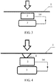
- FIG. 3 is a schematic structural diagram of an apparatus for powering on a terminal according to an embodiment of the present invention.
- the apparatus for powering on a terminal includes:
- a manner of the electrical connection not only includes a manner of direct physical contact or electrical contact between different modules or units, but also includes cooperation or interaction between different modules or units without the direct physical contact or the electrical contact.
- the set condition may be: the collected value of the pressure is greater than or equal to a preset threshold.
- the pressure detection unit 2 is disposed under the housing 1 of the terminal and is adjacent to or contacts the housing 1 of the terminal, so as to accurately collect the pressure generated when the user presses the housing of the terminal. In this way, when the pressure generated when the user presses the housing 1 of the terminal deforms the housing 1 of the terminal, the pressure detection unit 2 can accurately detect force of the pressure from the user in real time. It may be understood that, for a purpose of reducing costs, the pressure detection unit 2 does not need to be disposed under the entire housing 1 of the terminal, a specific position on the housing 1 of the terminal may be designated as a power-on press position, and accordingly, the pressure detection unit 2 is disposed only under the specific position on the housing 1 of the terminal. Certainly, multiple specific positions may also be disposed on the housing 1 of the terminal as power-on press positions, and accordingly, pressure detection units 2 are disposed only under the multiple specific positions on the housing 1 of the terminal.
- a data interface of the pressure detection unit 2 may output information about the value of the pressure.
- These data interfaces typically transmit data through multiple communications buses (such as an SPI bus and an I2C bus) for output.
- a data interface of a pressure detection unit 2 outputs a set of data to a processor, and software in the processor analyzes and processes the data and implements a corresponding key function (such as a menu key, an Enter key, and a play key).
- the pressure detection unit 2 may output the interrupt request when the value of the pressure is greater than or equal to the threshold.
- the output of the interrupt request requires only one interrupt request line (a solid line with an arrow in FIG. 3 or FIG. 4 ), the interrupt request line may be directly connected to a corresponding interface of the power supply module 3, the power supply module 3 is triggered, and an effect of the triggering is exactly the same as an effect of a physical on/off button.
- the power supply module 3 may be an integrated PMU, or may be a combination (for example, a combination of a DC-DC convertor, a linear regulator, an overvoltage protection circuit, and the like) of discrete power management components and the like.
- a main function of the power supply module 3 is responding to the interrupt request and outputting the power supply maintaining signal, and the power supply module may further provide different-voltage multi-level power supplies required by a master chip and one or more other parts (such as a radio frequency device and a camera module), so that these units can work properly.
- a pressure detection unit is disposed inside a housing 11 of a terminal.
- a user needs only to press the housing 1 of the terminal, and then the pressure detection unit 2 can detect pressure and output an interrupt request to a power supply module 3 to implement a power-on effect.
- the housing of the terminal does not need to be holed to dispose a power-on button, thereby improving waterproof and dustproof effects.
- FIG. 4 is a schematic structural diagram of another apparatus for powering on a terminal according to an embodiment of the present invention.
- the apparatus includes a pressure detection unit 2, disposed inside a housing 1 of a terminal and configured to collect a value of pressure (pressure indicated by an arrow in the figure) generated when a user presses the housing 1 of the terminal, and output an interrupt request when the value of the pressure collected by the pressure detection unit 2 meets a set condition; a power supply module 3, electrically connected to the pressure detection unit 2 and configured to respond to the interrupt request, and output a power supply maintaining signal to power on the terminal; and a protrusion part 4, where the protrusion part disposed on the housing of the terminal is located between the housing 1 of the terminal and the pressure detection unit 2 and is in contact with the pressure detection unit 2, so that the pressure detection unit 2 more effectively detects pressure generated when the housing 1 of the terminal deforms.
- a pressure detection unit 2 disposed inside a housing 1 of a terminal and configured to collect a value of pressure (pressure indicated by an arrow in the
- a difference from the embodiment provided in FIG. 3 lies in that the protrusion part 4 exists between the pressure detection unit 2 and the housing 1 of the terminal.
- a gap may exist between the housing 1 of the terminal and the pressure detection unit 2; therefore, adding a protrusion part 4 may alleviate a problem that the pressure detection unit 2 cannot detect pressure on the housing 1 of the terminal because a gap between the pressure detection unit 2 and the housing 1 of the terminal is too wide due to reasons such as thermal expansions and contractions.
- the protrusion part 4 is arc-shaped.
- a pressure detection unit is disposed inside a housing of a terminal.
- a user needs only to press the housing of the terminal, and then the pressure detection unit can detect pressure and output an interrupt request to a power supply module to implement a power-on effect.
- a protrusion part is disposed on the housing of the terminal, which may alleviate a problem that the pressure detection unit cannot detect pressure on the housing of the terminal because a gap between the pressure detection unit and the housing of the terminal is too wide due to reasons such as thermal expansions and contractions.
Landscapes
- Engineering & Computer Science (AREA)
- Theoretical Computer Science (AREA)
- General Engineering & Computer Science (AREA)
- Computer Hardware Design (AREA)
- Physics & Mathematics (AREA)
- General Physics & Mathematics (AREA)
- Human Computer Interaction (AREA)
- Telephone Function (AREA)
- Power Sources (AREA)
Abstract
Description
- This application claims priority to Chinese Patent Application No.
201310565859.2 - Embodiments of the present invention relate to the field of electronic technologies, and in particular, to a method and an apparatus for powering on a terminal.
- At present, it is relatively common that a menu key, an Enter key, and the like of a terminal typically adopt a virtual key manner.
- The virtual key manner is using software to detect a variation of a detection value, such as a value of pressure or a value of capacitance, in a corresponding position after key pressing, so as to determine an intention of pressing the key by a user. A precondition of the software detection is that power is supplied to a system, and therefore the existing virtual key manner applies only to the menu key, the Enter key, and the like, and cannot apply to a power-on button.
- At present, the power-on button of the terminal typically adopts a physical button manner.
- The physical button manner is that a metal contact under the power-on button contacts a circuit board after a user presses the power-on button, so that a current forms a loop, thereby implementing a power-on function.
- In the physical button manner, a surface of the terminal needs to be holed. As a result, a gap is left between the power-on button and a housing of the terminal, which does not facilitate integrated design of a terminal device, so that waterproof and dustproof difficulties increase.
- In view of this, embodiments of the present invention provide a method and an apparatus for powering on a terminal, so as to resolve a problem that a housing of a terminal must be holed to dispose a power-on button.
- According to a first aspect, a method for powering on a terminal is provided, including:
- collecting, by a pressure detection unit disposed inside a housing of a terminal, a value of pressure generated when a user presses the housing of the terminal, and
- sending, by the pressure detection unit, an interrupt request to a power supply module when the value of the pressure collected by the pressure detection unit meets a set condition; and
- responding, by the power supply module, to the interrupt request, and outputting a power supply maintaining signal to power on the terminal.
- In a first possible implementation manner of the first aspect, the set condition includes: the value of the pressure is greater than or equal to the set threshold.
- In a second possible implementation manner of the first aspect, before the responding, by the power supply module, to the interrupt request, and outputting a power supply maintaining signal, the power supply module further determines a size relationship between duration of the interrupt request and a preset minimum power-on time, and outputs the power supply maintaining signal when the duration of the interrupt request is greater than or equal to the preset minimum power-on time.
- With reference to the second possible implementation manner of the first aspect, in a third possible implementation manner, the minimum power-on time is 500 ms to 3s.
- According to a second aspect, an apparatus for powering on a terminal is provided, including:
- a pressure detection unit, disposed inside a housing of a terminal and configured to collect a value of pressure generated when a user presses the housing of the terminal,
- and output an interrupt request when the value of the pressure collected by the pressure detection unit meets a set condition; and
- a power supply module, electrically connected to the pressure detection unit and configured to respond to the interrupt request, and output a power supply maintaining signal to power on the terminal.
- In a first possible implementation manner of the second aspect, the set condition includes: the value of the pressure is greater than or equal to the set threshold.
- In a second possible implementation manner of the second aspect, the power supply module includes:
- a time determining unit, configured to determine a size relationship between duration of the interrupt request and a preset minimum power-on time, and output the power supply maintaining signal when the duration of the interrupt request is greater than or equal to the preset minimum power-on time.
- With reference to the second possible implementation manner of the second aspect, in a third possible implementation manner, the minimum power-on time is 500 ms to 3s. In a fourth possible implementation manner of the second aspect, a protrusion part is disposed on the housing of the terminal, and the protrusion part is located between the housing of the terminal and the pressure detection unit and is in contact with the pressure detection unit, so as to reduce a gap between the housing of the terminal and the pressure detection unit.
- With reference to the fourth possible implementation manner of the second aspect, in a fifth possible implementation manner, the protrusion part is arc-shaped.
- According to the foregoing solutions, a pressure detection unit is disposed inside a housing of a terminal. A user needs only to press the housing of the terminal, and then the pressure detection unit can detect pressure and output an interrupt request to a power supply module to implement a power-on effect. The housing of the terminal does not need to be holed to dispose a power-on button, thereby improving waterproof and dustproof effects.
- To describe the technical solutions in the embodiments of the present invention more clearly, the following briefly introduces the accompanying drawings required for describing the embodiments. Apparently, the accompanying drawings in the following description show merely some embodiments of the present invention, and persons of ordinary skill in the art may still derive other drawings from these accompanying drawings without creative efforts.
-
FIG. 1 is a flowchart of a method for powering on a terminal according to an embodiment of the present invention; -
FIG. 2 is a schematic waveform diagram of a power-on process according to an embodiment of the present invention; -
FIG. 3 is a schematic structural diagram of an apparatus for powering on a terminal according to an embodiment of the present invention; and -
FIG. 4 is a schematic structural diagram of another apparatus for powering on a terminal according to an embodiment of the present invention. -
- 1.
Housing 2. Pressure detection unit - 3.
Power supply module 4. Protrusion part - To make the objectives, technical solutions, and advantages of the embodiments of the present invention clearer, the following clearly and completely describes the technical solutions in the embodiments of the present invention with reference to the accompanying drawings in the embodiments of the present invention. Apparently, the described embodiments are some but not all of the embodiments of the present invention. All other embodiments obtained by persons of ordinary skill in the art based on the embodiments of the present invention without creative efforts shall fall within the protection scope of the present invention.
- The technical solutions in the embodiments of the present invention may apply to various terminals, such as a smartphone, a tablet, and a computer device, an information display device, or a communications device with a pressure detection unit. The pressure detection unit in the embodiments may be a pressure sensor.
- An embodiment of the present invention provides a method for powering on a terminal. Referring to
FIG. 1 , a procedure of the method is as follows: - 101. A pressure detection unit disposed inside a housing of a terminal collects a value of pressure generated when a user presses the housing of the terminal.
- The housing of the terminal bears the pressure generated when the user presses the housing of the terminal. The pressure detection unit is disposed under the housing of the terminal and is adjacent to or in contact with the housing of the terminal, so as to accurately collect the pressure generated when the user presses the housing of the terminal. In this way, when the pressure generated when the user presses the housing of the terminal deforms the housing of the terminal, the pressure detection unit can accurately detect force of the pressure from the user in real time. It may be understood that, for a purpose of reducing costs, the pressure detection unit does not need to be disposed under the entire housing of the terminal; instead, a specific position on the housing of the terminal may be designated as a power-on press position, and accordingly, the pressure detection unit is disposed only under the specific position on the housing of the terminal. Certainly, multiple specific positions may also be disposed on the terminal as power-on press positions, and accordingly, pressure detection units are disposed only under the multiple specific positions on the housing of the terminal.
- 102. The pressure detection unit sends an interrupt request to a power supply module when the value of the pressure collected by the pressure detection unit meets a set condition.
- Optionally, the set condition may be: the collected value of the pressure is greater than or equal to a preset threshold.
- It should be noted that, on the one hand, when the pressure detection unit collects the value of the pressure, a data interface of the pressure detection unit may output information about the value of the pressure. The data interface transmits data through multiple communications buses, such as a synchronous serial communications (Serial Peripheral Interface, SPI) bus and a full-duplex synchronous data transfer (Inter-Integrated Circuit, I2C) bus. In a virtual key solution in the prior art, a data interface of a pressure detection unit outputs a set of data to a processor, and the processor and software invoked by the processor analyze and process the data and implement a corresponding key function (such as a menu key, an Enter key, and a play key). However, in a case in which a power supply is not started, the processor cannot analyze and process the data, and therefore a power-on effect cannot be achieved according to the existing virtual key method. On the other hand, the pressure detection unit may output the interrupt request when the collected value of the pressure meets the set condition (for example, the value of the pressure is greater than or equal to the threshold). The output of the interrupt request requires only one interrupt request line, the interrupt request line may be directly connected to a corresponding interface of the power supply module, the interrupt request may trigger the power supply module, and an effect of the triggering is exactly the same as an effect of a physical on/off button. Therefore, in a power-off state, the pressure detection unit may be allowed to monitor a variation of a value of external pressure in real time, provided that a quite small amount of electricity is supplied to the pressure detection unit so that the pressure detection unit is always in an operating state. When collecting a value of pressure greater than or equal to the threshold, the pressure detection unit outputs the interrupt request to the power supply module as a signal for triggering the power supply module.
- 103. The power supply module responds to the interrupt request, and outputs a power supply maintaining signal to power on the terminal.
- The power supply module may be an integrated power management unit (Power Management Unit, PMU), or may be a combination (for example, a combination of a DC-DC convertor, a linear regulator, an overvoltage protection circuit, and the like) of discrete power management components and the like.
- It should be noted that a function of the interrupt request is triggering the power supply module, and after the power supply module is triggered, the power supply module has a self-memory function, that is, the power supply module is capable of continues outputting the power supply maintaining signal after the interrupt request disappears.
- It should be noted that after the power supply module is triggered, a power supply may be converted into multiple different power supply maintaining signals by using an internal circuit such as a DC-DC conversion circuit, so as to provide different multi-level power supplies required by a master chip and one or more other parts (such as a radio frequency device and a camera module), so that all these units can work properly.
- A further preferred step of step 103 is recording, by the power supply module, duration of the interrupt request after receiving the interrupt request, and outputting the power supply maintaining signal when the duration is greater than or equal to a preset minimum power-on time (refer to
FIG. 2 ). - Optionally, the minimum power-on time is 500 ms to 3s.
- False triggering may be generated because the pressure detection unit cannot recognize a source and a purpose of the external pressure. In this case, the false triggering may be relatively reduced by recording the duration of the interrupt request, comparing the duration of the interrupt request with the preset minimum power-on time, and starting the power supply only in a case in which the duration of the interrupt request is greater than or equal to the minimum power-on time. The optional minimum power-on time provided in this embodiment of the present invention is 500 ms to 3s, considering that the minimum power-on time should not be set to a long time, and an effect of user experience is definitely affected if the terminal is not powered on after long-time pressing.
- In this embodiment of the present invention, a pressure detection unit is disposed inside a housing of a terminal. A user needs only to press the housing of the terminal, and then the pressure detection unit can detect pressure and output an interrupt request to a power supply module to implement a power-on effect. The housing of the terminal does not need to be holed to dispose a power-on button, thereby improving waterproof and dustproof effects.
- Another embodiment of the present invention provides an apparatus for powering on a terminal.
FIG. 3 is a schematic structural diagram of an apparatus for powering on a terminal according to an embodiment of the present invention. The apparatus for powering on a terminal includes: - a
pressure detection unit 2, disposed inside ahousing 1 of a terminal and configured to collect a value of pressure (pressure indicated by an arrow in the figure) generated when a user presses thehousing 1 of the terminal, and output an interrupt request ("int" in the figure is short for interruption, indicating the interrupt request) when the value of the pressure collected by thepressure detection unit 2 meets a set condition; and - a
power supply module 3, electrically connected to thepressure detection unit 2 and configured to respond to the interrupt request, and output a power supply maintaining signal to power on the terminal. - A manner of the electrical connection not only includes a manner of direct physical contact or electrical contact between different modules or units, but also includes cooperation or interaction between different modules or units without the direct physical contact or the electrical contact.
- Optionally, the set condition may be: the collected value of the pressure is greater than or equal to a preset threshold.
- In this embodiment of the present invention, the
pressure detection unit 2 is disposed under thehousing 1 of the terminal and is adjacent to or contacts thehousing 1 of the terminal, so as to accurately collect the pressure generated when the user presses the housing of the terminal. In this way, when the pressure generated when the user presses thehousing 1 of the terminal deforms thehousing 1 of the terminal, thepressure detection unit 2 can accurately detect force of the pressure from the user in real time. It may be understood that, for a purpose of reducing costs, thepressure detection unit 2 does not need to be disposed under theentire housing 1 of the terminal, a specific position on thehousing 1 of the terminal may be designated as a power-on press position, and accordingly, thepressure detection unit 2 is disposed only under the specific position on thehousing 1 of the terminal. Certainly, multiple specific positions may also be disposed on thehousing 1 of the terminal as power-on press positions, and accordingly,pressure detection units 2 are disposed only under the multiple specific positions on thehousing 1 of the terminal. - In this embodiment of the present invention, on the one hand, when the
pressure detection unit 2 collects the value of the pressure, a data interface of thepressure detection unit 2 may output information about the value of the pressure. These data interfaces typically transmit data through multiple communications buses (such as an SPI bus and an I2C bus) for output. In a virtual key solution in the prior art, a data interface of apressure detection unit 2 outputs a set of data to a processor, and software in the processor analyzes and processes the data and implements a corresponding key function (such as a menu key, an Enter key, and a play key). - However, in a case in which a power supply is not started, the processor cannot analyze and process the data, and therefore a power-on effect cannot be achieved according to the existing virtual key method. On the other hand, the
pressure detection unit 2 may output the interrupt request when the value of the pressure is greater than or equal to the threshold. The output of the interrupt request requires only one interrupt request line (a solid line with an arrow inFIG. 3 or FIG. 4 ), the interrupt request line may be directly connected to a corresponding interface of thepower supply module 3, thepower supply module 3 is triggered, and an effect of the triggering is exactly the same as an effect of a physical on/off button. Thepower supply module 3 may be an integrated PMU, or may be a combination (for example, a combination of a DC-DC convertor, a linear regulator, an overvoltage protection circuit, and the like) of discrete power management components and the like. A main function of thepower supply module 3 is responding to the interrupt request and outputting the power supply maintaining signal, and the power supply module may further provide different-voltage multi-level power supplies required by a master chip and one or more other parts (such as a radio frequency device and a camera module), so that these units can work properly. - In the embodiment, a pressure detection unit is disposed inside a housing 11 of a terminal. A user needs only to press the
housing 1 of the terminal, and then thepressure detection unit 2 can detect pressure and output an interrupt request to apower supply module 3 to implement a power-on effect. The housing of the terminal does not need to be holed to dispose a power-on button, thereby improving waterproof and dustproof effects. - Still another embodiment of the present invention provides another apparatus for powering on a terminal.
FIG. 4 is a schematic structural diagram of another apparatus for powering on a terminal according to an embodiment of the present invention. The apparatus includes apressure detection unit 2, disposed inside ahousing 1 of a terminal and configured to collect a value of pressure (pressure indicated by an arrow in the figure) generated when a user presses thehousing 1 of the terminal, and output an interrupt request when the value of the pressure collected by thepressure detection unit 2 meets a set condition;
apower supply module 3, electrically connected to thepressure detection unit 2 and configured to respond to the interrupt request, and output a power supply maintaining signal to power on the terminal; and
aprotrusion part 4, where the protrusion part disposed on the housing of the terminal is located between thehousing 1 of the terminal and thepressure detection unit 2 and is in contact with thepressure detection unit 2, so that thepressure detection unit 2 more effectively detects pressure generated when thehousing 1 of the terminal deforms. - A difference from the embodiment provided in
FIG. 3 lies in that theprotrusion part 4 exists between thepressure detection unit 2 and thehousing 1 of the terminal. A gap may exist between thehousing 1 of the terminal and thepressure detection unit 2; therefore, adding aprotrusion part 4 may alleviate a problem that thepressure detection unit 2 cannot detect pressure on thehousing 1 of the terminal because a gap between thepressure detection unit 2 and thehousing 1 of the terminal is too wide due to reasons such as thermal expansions and contractions. - Optionally, the
protrusion part 4 is arc-shaped. - In this embodiment of the present invention, a pressure detection unit is disposed inside a housing of a terminal. A user needs only to press the housing of the terminal, and then the pressure detection unit can detect pressure and output an interrupt request to a power supply module to implement a power-on effect. In addition, a protrusion part is disposed on the housing of the terminal, which may alleviate a problem that the pressure detection unit cannot detect pressure on the housing of the terminal because a gap between the pressure detection unit and the housing of the terminal is too wide due to reasons such as thermal expansions and contractions.
- Finally, it should be noted that the above embodiments are merely intended for describing the technical solutions of the present invention other than limiting the present invention. Although the present invention is described in detail with reference to the foregoing embodiments, persons of ordinary skill in the art should understand that they may still make modifications to the technical solutions described in the foregoing embodiments or make equivalent substitutions to some technical features thereof, without departing from the spirit and scope of the technical solutions of the embodiments of the present invention.
Claims (10)
- A method for powering on a terminal, comprising the following steps:collecting, by a pressure detection unit disposed inside a housing of a terminal, a value of pressure generated when a user presses the housing of the terminal, and sending, by the pressure detection unit, an interrupt request to a power supply module when the value of the pressure collected by the pressure detection unit meets a set condition; andresponding, by the power supply module, to the interrupt request, and outputting a power supply maintaining signal to power on the terminal.
- The method according to claim 1, wherein the set condition comprises: the value of the pressure is greater than or equal to a preset threshold.
- The method according to claim 1 or 2, wherein before the responding, by the power supply module, to the interrupt request, and outputting a power supply maintaining signal, the power supply module further determines a size relationship between duration of the interrupt request and a preset minimum power-on time, and outputs the power supply maintaining signal when the duration of the interrupt request is greater than or equal to the preset minimum power-on time.
- The method according to claim 3, wherein the minimum power-on time ranges from 500 ms to 3s.
- An apparatus for powering on a terminal, comprising:a pressure detection unit, disposed inside a housing of a terminal and configured to collect a value of pressure generated when a user presses the housing of the terminal, and output an interrupt request when the value of the pressure collected by the pressure detection unit meets a set condition; anda power supply module, electrically connected to the pressure detection unit and configured to respond to the interrupt request, and output a power supply maintaining signal to power on the terminal.
- The apparatus for powering on a terminal according to claim 5, wherein the set condition comprises: the value of the pressure is greater than or equal to a preset threshold.
- The apparatus for powering on a terminal according to claim 5 or 6, wherein the power supply module comprises:a time determining unit, configured to determine a size relationship between duration of the interrupt request and a preset minimum power-on time, and output the power supply maintaining signal when the duration of the interrupt request is greater than or equal to the preset minimum power-on time.
- The apparatus for powering on a terminal according to claim 7, wherein the minimum power-on time ranges from 500 ms to 3s.
- The apparatus for powering on a terminal according to claim 5 or 6, wherein a protrusion part is disposed on the housing of the terminal, and the protrusion part is located between the housing of the terminal and the pressure detection unit and is in contact with the pressure detection unit.
- The apparatus for powering on a terminal according to claim 9, wherein the protrusion part is arc-shaped.
Applications Claiming Priority (2)
| Application Number | Priority Date | Filing Date | Title |
|---|---|---|---|
| CN201310565859.2A CN103605569A (en) | 2013-11-13 | 2013-11-13 | Method and device for terminal booting |
| PCT/CN2014/082145 WO2015070629A1 (en) | 2013-11-13 | 2014-07-14 | Startup method and apparatus for terminal |
Publications (2)
| Publication Number | Publication Date |
|---|---|
| EP3001315A1 true EP3001315A1 (en) | 2016-03-30 |
| EP3001315A4 EP3001315A4 (en) | 2016-08-31 |
Family
ID=50123798
Family Applications (1)
| Application Number | Title | Priority Date | Filing Date |
|---|---|---|---|
| EP14862513.0A Withdrawn EP3001315A4 (en) | 2013-11-13 | 2014-07-14 | Startup method and apparatus for terminal |
Country Status (4)
| Country | Link |
|---|---|
| US (1) | US9836106B2 (en) |
| EP (1) | EP3001315A4 (en) |
| CN (1) | CN103605569A (en) |
| WO (1) | WO2015070629A1 (en) |
Families Citing this family (5)
| Publication number | Priority date | Publication date | Assignee | Title |
|---|---|---|---|---|
| CN103605569A (en) | 2013-11-13 | 2014-02-26 | 华为终端有限公司 | Method and device for terminal booting |
| US10228740B2 (en) * | 2015-06-24 | 2019-03-12 | Intel Corporation | Sensor device and method |
| CN105281740A (en) * | 2015-07-24 | 2016-01-27 | 维沃移动通信有限公司 | Key device and terminal |
| CN105607856A (en) * | 2015-12-25 | 2016-05-25 | 惠州Tcl移动通信有限公司 | Push-type shutdown device for mobile terminal and method thereof |
| CN114995891A (en) * | 2022-05-31 | 2022-09-02 | 维沃移动通信有限公司 | Non-contact starting method and device |
Family Cites Families (17)
| Publication number | Priority date | Publication date | Assignee | Title |
|---|---|---|---|---|
| US6453169B1 (en) * | 1997-02-28 | 2002-09-17 | Qualcomm Incorporated | Portable radiotelephone with multiple function power key |
| US7176902B2 (en) | 2003-10-10 | 2007-02-13 | 3M Innovative Properties Company | Wake-on-touch for vibration sensing touch input devices |
| GB2409366A (en) * | 2003-12-16 | 2005-06-22 | Nokia Corp | sealed casing for a mobile electronic device such as a mobile phone |
| CN1690959A (en) * | 2004-04-22 | 2005-11-02 | 上海迪比特实业有限公司 | Portable information terminal and startup method thereof |
| DE102005007887B3 (en) * | 2005-02-21 | 2006-02-23 | Hansa Metallwerke Ag | Operating device for sanitary fitting has coupling devices extending perpendicular to operating direction of sensor, over its sensitive region |
| US7472291B2 (en) * | 2005-04-15 | 2008-12-30 | Shuttle Inc. | Method and apparatus for integrating ACPI functionality and power button functionality into a single power key |
| US20080018610A1 (en) * | 2006-07-20 | 2008-01-24 | John Paul Harmon | Method and system for extending the lifespan of a touch screen assembly |
| ATE523836T1 (en) | 2008-07-07 | 2011-09-15 | Tyco Electronics Services Gmbh | DEVICE FOR CHANGING THE OPERATING STATE OF A DEVICE |
| US8385885B2 (en) * | 2008-10-17 | 2013-02-26 | Sony Ericsson Mobile Communications Ab | Method of unlocking a mobile electronic device |
| CN101690959B (en) | 2009-09-28 | 2011-06-15 | 大连三高科技发展有限公司 | Thick-wall steel pipe welding extruded pipe device with adjustable supporting roll |
| US8862913B2 (en) * | 2009-10-02 | 2014-10-14 | Blackberry Limited | Method of switching power modes and a portable electronic device configured to perform the same |
| CN101877744A (en) * | 2010-06-22 | 2010-11-03 | 中兴通讯股份有限公司 | A terminal locking and unlocking method and device |
| CN101894036A (en) * | 2010-07-21 | 2010-11-24 | 中兴通讯股份有限公司 | A mobile terminal and booting method thereof |
| WO2013089048A1 (en) | 2011-12-16 | 2013-06-20 | 株式会社村田製作所 | Touch operation input device |
| CN102520627B (en) * | 2011-12-21 | 2014-05-07 | 深圳和而泰智能控制股份有限公司 | Handheld electronic equipment and control method thereof |
| US8878788B2 (en) * | 2012-01-09 | 2014-11-04 | Motorola Mobility Llc | Touch screen device with surface switch |
| CN103605569A (en) * | 2013-11-13 | 2014-02-26 | 华为终端有限公司 | Method and device for terminal booting |
-
2013
- 2013-11-13 CN CN201310565859.2A patent/CN103605569A/en active Pending
-
2014
- 2014-07-14 US US14/901,825 patent/US9836106B2/en not_active Expired - Fee Related
- 2014-07-14 WO PCT/CN2014/082145 patent/WO2015070629A1/en not_active Ceased
- 2014-07-14 EP EP14862513.0A patent/EP3001315A4/en not_active Withdrawn
Also Published As
| Publication number | Publication date |
|---|---|
| US20160161999A1 (en) | 2016-06-09 |
| CN103605569A (en) | 2014-02-26 |
| EP3001315A4 (en) | 2016-08-31 |
| WO2015070629A1 (en) | 2015-05-21 |
| US9836106B2 (en) | 2017-12-05 |
Similar Documents
| Publication | Publication Date | Title |
|---|---|---|
| US9836106B2 (en) | Method and apparatus for powering on a terminal | |
| EP2993756B1 (en) | Electronic device, method of controlling charging by electronic device | |
| CN109840006B (en) | Main control chip power supply device | |
| EP2884420B1 (en) | Method and apparatus for protecting terminal, and electronic device | |
| US10592023B2 (en) | Touch display assembly, touch input unit and touch input method | |
| US20170269659A1 (en) | Disconnecting a battery from a system | |
| US20120042183A1 (en) | Apparatus for adjusting computer power mode | |
| US20150318719A1 (en) | Charging method and electronic device | |
| CN210137424U (en) | Earphone hardware reset system | |
| CN201601754U (en) | Energy-saving television | |
| CN111623863A (en) | Electronic scale control method and electronic scale | |
| CN105204601A (en) | System automatic power-on circuit and method | |
| CN109739339B (en) | Control method and device | |
| US11170628B2 (en) | Monitoring device | |
| CN103488270B (en) | Electricity saving method and electronic installation thereof | |
| CN111026684B (en) | Interface control method, interface control device and storage medium | |
| CN110764398A (en) | Intelligent watch and mode switching method thereof | |
| CN109215656A (en) | Voice remote control device and method, storage medium, and electronic device | |
| CN212783224U (en) | Switch assembly and electronic equipment | |
| CN212873433U (en) | Writing pen and writing system | |
| CN211124965U (en) | Portable extended display screen control circuit capable of realizing automatic startup and shutdown | |
| TWI496035B (en) | Electrical syatem, input apparatus and charging method for input apparatus | |
| CN101676825A (en) | Electronic system and power supply device thereof | |
| CN104953649A (en) | Power supply circuit and electronic equipment | |
| CN113655851A (en) | Control method of electronic equipment, control device of electronic equipment, and electronic equipment |
Legal Events
| Date | Code | Title | Description |
|---|---|---|---|
| PUAI | Public reference made under article 153(3) epc to a published international application that has entered the european phase |
Free format text: ORIGINAL CODE: 0009012 |
|
| 17P | Request for examination filed |
Effective date: 20151222 |
|
| AK | Designated contracting states |
Kind code of ref document: A1 Designated state(s): AL AT BE BG CH CY CZ DE DK EE ES FI FR GB GR HR HU IE IS IT LI LT LU LV MC MK MT NL NO PL PT RO RS SE SI SK SM TR |
|
| AX | Request for extension of the european patent |
Extension state: BA ME |
|
| A4 | Supplementary search report drawn up and despatched |
Effective date: 20160729 |
|
| RIC1 | Information provided on ipc code assigned before grant |
Ipc: G06F 1/16 20060101ALI20160725BHEP Ipc: H03K 17/96 20060101ALN20160725BHEP Ipc: G06F 9/48 20060101AFI20160725BHEP Ipc: G06F 1/26 20060101ALI20160725BHEP |
|
| DAX | Request for extension of the european patent (deleted) | ||
| RAP1 | Party data changed (applicant data changed or rights of an application transferred) |
Owner name: HUAWEI DEVICE (DONGGUAN) CO., LTD. |
|
| STAA | Information on the status of an ep patent application or granted ep patent |
Free format text: STATUS: EXAMINATION IS IN PROGRESS |
|
| 17Q | First examination report despatched |
Effective date: 20181122 |
|
| RAP1 | Party data changed (applicant data changed or rights of an application transferred) |
Owner name: HUAWEI DEVICE CO., LTD. |
|
| STAA | Information on the status of an ep patent application or granted ep patent |
Free format text: STATUS: THE APPLICATION HAS BEEN WITHDRAWN |
|
| 18W | Application withdrawn |
Effective date: 20200728 |