EP3001248A1 - Production process for optically shaped product and production process for liquid discharge head - Google Patents
Production process for optically shaped product and production process for liquid discharge head Download PDFInfo
- Publication number
- EP3001248A1 EP3001248A1 EP15002614.4A EP15002614A EP3001248A1 EP 3001248 A1 EP3001248 A1 EP 3001248A1 EP 15002614 A EP15002614 A EP 15002614A EP 3001248 A1 EP3001248 A1 EP 3001248A1
- Authority
- EP
- European Patent Office
- Prior art keywords
- photosensitive resin
- resin composition
- production process
- epoxy resin
- process according
- Prior art date
- Legal status (The legal status is an assumption and is not a legal conclusion. Google has not performed a legal analysis and makes no representation as to the accuracy of the status listed.)
- Granted
Links
Images



Classifications
-
- G—PHYSICS
- G03—PHOTOGRAPHY; CINEMATOGRAPHY; ANALOGOUS TECHNIQUES USING WAVES OTHER THAN OPTICAL WAVES; ELECTROGRAPHY; HOLOGRAPHY
- G03F—PHOTOMECHANICAL PRODUCTION OF TEXTURED OR PATTERNED SURFACES, e.g. FOR PRINTING, FOR PROCESSING OF SEMICONDUCTOR DEVICES; MATERIALS THEREFOR; ORIGINALS THEREFOR; APPARATUS SPECIALLY ADAPTED THEREFOR
- G03F7/00—Photomechanical, e.g. photolithographic, production of textured or patterned surfaces, e.g. printing surfaces; Materials therefor, e.g. comprising photoresists; Apparatus specially adapted therefor
- G03F7/0005—Production of optical devices or components in so far as characterised by the lithographic processes or materials used therefor
-
- B—PERFORMING OPERATIONS; TRANSPORTING
- B41—PRINTING; LINING MACHINES; TYPEWRITERS; STAMPS
- B41J—TYPEWRITERS; SELECTIVE PRINTING MECHANISMS, i.e. MECHANISMS PRINTING OTHERWISE THAN FROM A FORME; CORRECTION OF TYPOGRAPHICAL ERRORS
- B41J2/00—Typewriters or selective printing mechanisms characterised by the printing or marking process for which they are designed
- B41J2/005—Typewriters or selective printing mechanisms characterised by the printing or marking process for which they are designed characterised by bringing liquid or particles selectively into contact with a printing material
- B41J2/01—Ink jet
- B41J2/135—Nozzles
- B41J2/16—Production of nozzles
- B41J2/1601—Production of bubble jet print heads
- B41J2/1603—Production of bubble jet print heads of the front shooter type
-
- B—PERFORMING OPERATIONS; TRANSPORTING
- B41—PRINTING; LINING MACHINES; TYPEWRITERS; STAMPS
- B41J—TYPEWRITERS; SELECTIVE PRINTING MECHANISMS, i.e. MECHANISMS PRINTING OTHERWISE THAN FROM A FORME; CORRECTION OF TYPOGRAPHICAL ERRORS
- B41J2/00—Typewriters or selective printing mechanisms characterised by the printing or marking process for which they are designed
- B41J2/005—Typewriters or selective printing mechanisms characterised by the printing or marking process for which they are designed characterised by bringing liquid or particles selectively into contact with a printing material
- B41J2/01—Ink jet
- B41J2/135—Nozzles
- B41J2/16—Production of nozzles
- B41J2/1621—Manufacturing processes
- B41J2/1631—Manufacturing processes photolithography
-
- B—PERFORMING OPERATIONS; TRANSPORTING
- B41—PRINTING; LINING MACHINES; TYPEWRITERS; STAMPS
- B41J—TYPEWRITERS; SELECTIVE PRINTING MECHANISMS, i.e. MECHANISMS PRINTING OTHERWISE THAN FROM A FORME; CORRECTION OF TYPOGRAPHICAL ERRORS
- B41J2/00—Typewriters or selective printing mechanisms characterised by the printing or marking process for which they are designed
- B41J2/005—Typewriters or selective printing mechanisms characterised by the printing or marking process for which they are designed characterised by bringing liquid or particles selectively into contact with a printing material
- B41J2/01—Ink jet
- B41J2/135—Nozzles
- B41J2/16—Production of nozzles
- B41J2/1621—Manufacturing processes
- B41J2/1637—Manufacturing processes molding
- B41J2/1639—Manufacturing processes molding sacrificial molding
-
- B—PERFORMING OPERATIONS; TRANSPORTING
- B41—PRINTING; LINING MACHINES; TYPEWRITERS; STAMPS
- B41J—TYPEWRITERS; SELECTIVE PRINTING MECHANISMS, i.e. MECHANISMS PRINTING OTHERWISE THAN FROM A FORME; CORRECTION OF TYPOGRAPHICAL ERRORS
- B41J2/00—Typewriters or selective printing mechanisms characterised by the printing or marking process for which they are designed
- B41J2/005—Typewriters or selective printing mechanisms characterised by the printing or marking process for which they are designed characterised by bringing liquid or particles selectively into contact with a printing material
- B41J2/01—Ink jet
- B41J2/135—Nozzles
- B41J2/16—Production of nozzles
- B41J2/1621—Manufacturing processes
- B41J2/164—Manufacturing processes thin film formation
- B41J2/1645—Manufacturing processes thin film formation thin film formation by spincoating
-
- G—PHYSICS
- G03—PHOTOGRAPHY; CINEMATOGRAPHY; ANALOGOUS TECHNIQUES USING WAVES OTHER THAN OPTICAL WAVES; ELECTROGRAPHY; HOLOGRAPHY
- G03F—PHOTOMECHANICAL PRODUCTION OF TEXTURED OR PATTERNED SURFACES, e.g. FOR PRINTING, FOR PROCESSING OF SEMICONDUCTOR DEVICES; MATERIALS THEREFOR; ORIGINALS THEREFOR; APPARATUS SPECIALLY ADAPTED THEREFOR
- G03F7/00—Photomechanical, e.g. photolithographic, production of textured or patterned surfaces, e.g. printing surfaces; Materials therefor, e.g. comprising photoresists; Apparatus specially adapted therefor
- G03F7/004—Photosensitive materials
- G03F7/0045—Photosensitive materials with organic non-macromolecular light-sensitive compounds not otherwise provided for, e.g. dissolution inhibitors
-
- G—PHYSICS
- G03—PHOTOGRAPHY; CINEMATOGRAPHY; ANALOGOUS TECHNIQUES USING WAVES OTHER THAN OPTICAL WAVES; ELECTROGRAPHY; HOLOGRAPHY
- G03F—PHOTOMECHANICAL PRODUCTION OF TEXTURED OR PATTERNED SURFACES, e.g. FOR PRINTING, FOR PROCESSING OF SEMICONDUCTOR DEVICES; MATERIALS THEREFOR; ORIGINALS THEREFOR; APPARATUS SPECIALLY ADAPTED THEREFOR
- G03F7/00—Photomechanical, e.g. photolithographic, production of textured or patterned surfaces, e.g. printing surfaces; Materials therefor, e.g. comprising photoresists; Apparatus specially adapted therefor
- G03F7/004—Photosensitive materials
- G03F7/038—Macromolecular compounds which are rendered insoluble or differentially wettable
-
- G—PHYSICS
- G03—PHOTOGRAPHY; CINEMATOGRAPHY; ANALOGOUS TECHNIQUES USING WAVES OTHER THAN OPTICAL WAVES; ELECTROGRAPHY; HOLOGRAPHY
- G03F—PHOTOMECHANICAL PRODUCTION OF TEXTURED OR PATTERNED SURFACES, e.g. FOR PRINTING, FOR PROCESSING OF SEMICONDUCTOR DEVICES; MATERIALS THEREFOR; ORIGINALS THEREFOR; APPARATUS SPECIALLY ADAPTED THEREFOR
- G03F7/00—Photomechanical, e.g. photolithographic, production of textured or patterned surfaces, e.g. printing surfaces; Materials therefor, e.g. comprising photoresists; Apparatus specially adapted therefor
- G03F7/004—Photosensitive materials
- G03F7/09—Photosensitive materials characterised by structural details, e.g. supports, auxiliary layers
- G03F7/095—Photosensitive materials characterised by structural details, e.g. supports, auxiliary layers having more than one photosensitive layer
-
- G—PHYSICS
- G03—PHOTOGRAPHY; CINEMATOGRAPHY; ANALOGOUS TECHNIQUES USING WAVES OTHER THAN OPTICAL WAVES; ELECTROGRAPHY; HOLOGRAPHY
- G03F—PHOTOMECHANICAL PRODUCTION OF TEXTURED OR PATTERNED SURFACES, e.g. FOR PRINTING, FOR PROCESSING OF SEMICONDUCTOR DEVICES; MATERIALS THEREFOR; ORIGINALS THEREFOR; APPARATUS SPECIALLY ADAPTED THEREFOR
- G03F7/00—Photomechanical, e.g. photolithographic, production of textured or patterned surfaces, e.g. printing surfaces; Materials therefor, e.g. comprising photoresists; Apparatus specially adapted therefor
- G03F7/16—Coating processes; Apparatus therefor
-
- G—PHYSICS
- G03—PHOTOGRAPHY; CINEMATOGRAPHY; ANALOGOUS TECHNIQUES USING WAVES OTHER THAN OPTICAL WAVES; ELECTROGRAPHY; HOLOGRAPHY
- G03F—PHOTOMECHANICAL PRODUCTION OF TEXTURED OR PATTERNED SURFACES, e.g. FOR PRINTING, FOR PROCESSING OF SEMICONDUCTOR DEVICES; MATERIALS THEREFOR; ORIGINALS THEREFOR; APPARATUS SPECIALLY ADAPTED THEREFOR
- G03F7/00—Photomechanical, e.g. photolithographic, production of textured or patterned surfaces, e.g. printing surfaces; Materials therefor, e.g. comprising photoresists; Apparatus specially adapted therefor
- G03F7/26—Processing photosensitive materials; Apparatus therefor
- G03F7/30—Imagewise removal using liquid means
- G03F7/32—Liquid compositions therefor, e.g. developers
- G03F7/325—Non-aqueous compositions
-
- B—PERFORMING OPERATIONS; TRANSPORTING
- B41—PRINTING; LINING MACHINES; TYPEWRITERS; STAMPS
- B41J—TYPEWRITERS; SELECTIVE PRINTING MECHANISMS, i.e. MECHANISMS PRINTING OTHERWISE THAN FROM A FORME; CORRECTION OF TYPOGRAPHICAL ERRORS
- B41J2/00—Typewriters or selective printing mechanisms characterised by the printing or marking process for which they are designed
- B41J2/005—Typewriters or selective printing mechanisms characterised by the printing or marking process for which they are designed characterised by bringing liquid or particles selectively into contact with a printing material
- B41J2/01—Ink jet
- B41J2/135—Nozzles
- B41J2/14—Structure thereof only for on-demand ink jet heads
- B41J2002/14475—Structure thereof only for on-demand ink jet heads characterised by nozzle shapes or number of orifices per chamber
Definitions
- the present invention relates to a production process for an optically shaped product and a production process for a liquid discharge head using this production process.
- a liquid discharge head discharging a liquid may be mentioned.
- the liquid discharge head is used for discharging an ink in an ink jet recording apparatus as, for example, an ink jet recording head.
- the liquid discharge head applied to the ink jet recording generally includes plural fine discharge ports, flow paths respectively communicating with the discharge ports and discharge energy generating elements each provided at a part of the flow path for generating energy for discharging a liquid within the flow path.
- a process of laminating a low-sensitive photosensitive resin layer forming a flow path and a high-sensitive photosensitive resin layer which will become a discharge port by patterning on a substrate in which a discharge energy generating element has been provided in advance is known.
- the low-sensitive photosensitive resin layer and the high-sensitive photosensitive resin layer are respectively cured, and uncured portions thereof are then removed, thereby forming the flow path and the discharge port on the substrate.
- a film of a low-sensitive photosensitive resin which is liquid is first formed on a substrate by a spin-coating method, and the film is exposed to be in a form of a flow path.
- a dry film of a high-sensitive photosensitive resin is then laminated on the resultant low-sensitive photosensitive resin layer and exposed to be in a form of a discharge port, uncured portions of the low-sensitive photosensitive resin layer and the high-sensitive photosensitive resin layer are collectively removed to form the flow path and the discharge port.
- the substrate is etched from a surface on which none of the photosensitive resin layers was laminated to form a supply path for supplying a liquid to the flow path passing through the substrate.
- a production process for an optically shaped product which comprises applying a photosensitive resin composition in a form of a dry film on to a substrate in which a hole opening to a surface thereof is formed so as to cover the hole and performing patterning to form an optically shaped product, wherein the photosensitive resin composition contains a resin comprising a tri- or higher functional epoxy resin and a bifunctional epoxy resin, the bifunctional epoxy resin has a weight-average molecular weight (Mw) of 5,500 to 60,000, the resin has a weight-average molecular weight (Mw) ranging from 4,500 to 11,000, and a mixing ratio by mass between the tri- or higher functional epoxy resin and the bifunctional epoxy resin satisfies (b)/(a) ⁇ 1.5, where (a) is a mass of the tri- or higher functional epoxy resin, and (b) is a mass of the bifunctional epoxy resin.
- Mw weight-average molecular weight
- Mw weight-average molecular weight
- Mw weight-average molecular weight
- a production process for a liquid discharge head which comprises applying a photosensitive resin composition in a form of a dry film on to a substrate in which a discharge energy generating element and a liquid supply path for liquid are formed, wherein the photosensitive resin composition contains a resin comprising a tri- or higher functional epoxy resin and a bifunctional epoxy resin, the bifunctional epoxy resin has a weight-average molecular weight (Mw) of 5,500 to 60,000, the resin has a weight-average molecular weight (Mw) ranging from 4,500 to 11,000, and a mixing ratio by mass between the tri- or higher functional epoxy resin and the bifunctional epoxy resin satisfies (b)/(a) ⁇ 1.5, where (a) is a mass of the tri- or higher functional epoxy resin, and (b) is a mass of the bifunctional epoxy resin.
- Mw weight-average molecular weight
- Mw weight-average molecular weight
- Mw weight-average molecular weight
- Mw weight-average molecular weight
- Mw weight
- a low-sensitive photosensitive resin layer is formed on a substrate by a spin-coating method, so that the formation of a supply path is conducted only after the formation of the low-sensitive photosensitive resin layer.
- etching for forming the supply path in the substrate can be conducted only from the surface on which no photosensitive resin layer is formed, so that the step for forming the supply path is highly restricted.
- the discharge port height means a distance from the surface of the substrate to a position of the discharge port.
- Another object of the present invention is to provide a production process for a liquid discharge head by laminating a photosensitive resin layer on a substrate in which a supply path is formed in advance, by which falling-in of the photosensitive resin layer into the supply path is small, and a flow path height and a discharge port height can be made even.
- FIG. 1A is a schematic perspective view illustrating a liquid discharge head produced according to a production process of this embodiment
- FIG. 1B is a schematic sectional view taken along line 1B-1B in FIG. 1A and illustrates a sectional construction at a surface perpendicular to a substrate.
- This liquid discharge head has a substrate 2 in which a plurality of discharge energy generating elements 1 for generating energy utilized for discharging a liquid are formed at predetermined pitches.
- a supply path 3 for liquid is provided as a through-hole in the substrate 2.
- a flow path 5 Side walls of a flow path 5 are formed on one surface of the substrate 2 by a flow path forming member 4, and a discharge port forming member 8 in which a discharge port 6 is provided as a through-hole is formed on the flow path forming member 4 and the flow path 5.
- a water-repellent layer 9 is formed on the discharge port forming member 8 as needed.
- This liquid discharge head discharges a liquid supplied through the flow path 5 from the supply path 3 as a droplet from the discharge port 6 by applying a pressure generated by the discharge energy generating element 1 to the liquid.
- FIGS. 2A to 2E are schematic sectional views illustrating steps for producing the liquid discharge head in this embodiment in order.
- FIG. 2E illustrates a view viewed at the same sectional position as FIG. 1B , which illustrates a state of completion.
- two kinds of photosensitive resin compositions of a photosensitive resin composition (1) and a photosensitive resin composition (2) are used as described below. These photosensitive resin compositions are different in sensitivity to light used for patterning, and the photosensitive resin composition (2) has sensitivity higher than the photosensitive resin composition (1).
- the sensitivity means an amount of exposure which is necessary for curing the photosensitive resin compositions, and the photosensitive resin composition with higher sensitivity is cured with a smaller amount of exposure.
- the photosensitive resin composition (1) is first applied on to a film substrate composed of polyethylene terephthalate (PET) or polyimide
- the photosensitive resin composition (1) is transferred on to a substrate 2 in which a discharge energy generating element 1 is arranged by means of a laminating method, thereby forming a film.
- a first photosensitive resin composition layer 10 composed of an uncured photosensitive resin composition (1) is thereby formed on the substrate 2 as illustrated in FIG. 2A .
- a supply path 3 is provided in the substrate 2, and the supply path 3 forms a hole opening to surfaces of the substrate 2.
- the first photosensitive resin composition layer 10 is formed so as to cover this hole and applied in a form of a dry film to the surface of the substrate 2.
- the photosensitive resin composition (1) constituting the first photosensitive resin composition layer 10 is a negative photosensitive epoxy resin composition containing a resin comprising a tri- or higher functional epoxy resin (a) and a bifunctional epoxy resin (b). The composition thereof will be described in detail below.
- the first photosensitive resin composition layer 10 is then subjected to pattern exposure through a flow path forming mask 11 having a flow path pattern, and the exposed portion is cured by additionally conducting a heat treatment (post exposure bake) to form a flow path forming member 4 as illustrated in FIG. 2B .
- the unexposed portion remains as an uncured first photosensitive resin composition layer 10.
- the flow path forming mask 11 is a photomask and is obtained by forming a light shielding film 11A such as a chromium film according to a pattern such as a flow path on a substrate composed of a material such as glass or quartz transmitting light of an exposure wavelength.
- a light source of a single wavelength such as an i-line exposure stepper or a KrF stepper, or a projection exposure apparatus having a light source of a broad wavelength of a mercury lamp, such as Mask Aligner MPA-600 Super (trade name, manufactured by Canon Inc.), may be used.
- the photosensitive resin composition (2) is then applied on to a film substrate composed of PET or polyimide to form a film. Thereafter, the photosensitive resin composition (2) is transferred in a form of a dry film on to the first photosensitive resin composition layer 10 and the flow path forming member 4 by means of a laminating method to form a second photosensitive resin composition layer 12. Accordingly, the photosensitive resin composition (2) is laminated in a form of a dry film on the photosensitive resin composition (1). A water-repellent layer 9 is additionally formed on the second photosensitive resin composition layer 12 as needed as illustrated in FIG. 2C . An epoxy-resin-based negative epoxy resin composition is suitably used as the photosensitive resin composition (2). The composition thereof will be described in detail below.
- the water-repellent layer 9 is required to have repellency with respect to a liquid discharged from the liquid discharge head.
- a perfluoroalkyl composition or perfluoropolyether composition having cationic polymerizability is suitably used as the water-repellent layer 9.
- the perfluoroalkyl composition or perfluoropolyether composition is generally known to segregate a fluorinated alkyl chain at an interface between the composition and air by a bake treatment after the application thereof.
- the water-repellency of the surface of the composition can be enhanced by this segregated fluorinated alkyl chain.
- the second photosensitive resin composition layer 12 and the water-repellent layer 9 are then subjected to pattern exposure through a discharge port forming mask 13 having a discharge port pattern, and the exposed portion is cured by additionally conducting a heat treatment (post exposure bake) to form a discharge port forming member 8 as illustrated in FIG. 2D .
- a heat treatment post exposure bake
- the photosensitive resin composition (2) requires to have relatively higher sensitivity regarding the exposure than the photosensitive resin composition (1).
- the discharge port forming mask 13 is obtained by forming a light shielding film 13A such as a chromium film according to a pattern such as a discharge port on a substrate composed of a material such as glass or quartz transmitting light of an exposure wavelength.
- a light shielding film 13A such as a chromium film
- the same apparatus as that used in the exposure of the first photosensitive resin composition layer 10 may be used as an exposure apparatus.
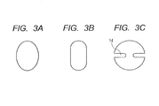
- the discharge port pattern i.e. the plane shape of the discharge port, may not always be circular and may be suitably determined in view of, for example, discharge characteristics, including the shapes illustrated in FIGS. 3A to 3C.
- FIG. 3A illustrates a discharge port of an elliptical shape
- FIG. 3A illustrates a discharge port of an elliptical shape
- FIG. 3B illustrates a discharge port formed of an elongated opening whose both ends are formed into a semicircle.
- FIG. 3C illustrates a circular discharge port in which a pair of projections 14 toward a central portion thereof is provided.
- a discharge port of such a shape as illustrated in FIG. 3C is used, whereby a liquid can be held between the projections 14, thereby greatly reducing the situation that a droplet is divided into plural portions (main droplet and satellite) when the droplet is discharged.
- the discharge port having the plane shape as illustrated in FIG. 3C is used in the case where the liquid discharge head is an ink jet recording head, printing of a high-quality image can be realized.
- Unexposed portions of the first photosensitive resin composition layer 10, the second photosensitive resin composition layer 12 and the water-repellent layer 9 are collectively removed with an organic solvent to form a flow path 5 and a discharge port 6 as illustrated in FIG. 2E , and a heat treatment is then conducted as needed to complete a liquid discharge head.
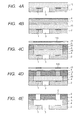
- FIGS. 4A to 4E are schematic sectional views illustrating steps for producing a liquid discharge head in this case in order.
- FIG. 4E illustrates a view viewed at the same sectional position as FIG. 1B , which illustrates a state of completion.
- the photosensitive resin composition (1) is transferred on to a substrate 2 in which a discharge energy generating element 1 is arranged by means of a laminating method, thereby forming a film.
- a supply path 3 forming a hole opening to surfaces of the substrate 2 is provided in the substrate 2, and this hole is covered with the first photosensitive resin composition (1).
- a first photosensitive resin composition layer 10 composed of an uncured photosensitive resin composition (1) is thereby formed on the substrate 2 as illustrated in FIG. 4A .
- the photosensitive resin composition (2) is transferred and laminated on the first photosensitive resin composition layer 10 by means of a laminating method to form a second photosensitive resin composition layer 12.
- a water-repellent layer 9 is formed on the second photosensitive resin composition layer 12 as needed as illustrated in FIG. 4B .
- the first photosensitive resin composition layer 10 and the second photosensitive resin composition layer 12 are then subjected to pattern exposure through a flow path forming mask 11 having a flow path pattern, and a heat treatment is additionally conducted to cure exposed portions.
- a flow path forming member 4 which will become side walls of a flow path is formed, and moreover a part of a discharge port forming member 8 is formed.
- the second photosensitive resin composition layer 12 and the water-repellent layer 9 are then subjected to pattern exposure through a discharge port forming mask 13 having a discharge port pattern as illustrated in FIG. 4D .
- a heat treatment is additionally conducted to cure exposed portions, thereby forming the discharge port forming member 8 in such a manner that only a position where a discharge port is to be formed becomes an uncured portion.
- Uncured portions of the first photosensitive resin composition layer 10, the second photosensitive resin composition layer 12 and the water-repellent layer 9 are collectively removed with an organic solvent to form a flow path 5 and a discharge port 6 as illustrated in FIG. 4E , and a heat treatment is conducted as needed to complete a liquid discharge head.
- the photosensitive resin composition (2) forming the second photosensitive resin composition layer 12 requires to have relatively higher sensitivity regarding the exposure than the photosensitive resin composition (1) forming the first photosensitive resin composition layer 10.
- the exposure of the discharge port pattern may be conducted before the exposure of the flow path pattern.
- Photosensitive resin composition (1) The respective photosensitive resin compositions used in this embodiment will now be described.
- the photosensitive resin composition (1) forming the first photosensitive resin composition layer 10 is a negative photosensitive epoxy resin composition containing a resin comprising a tri- or higher functional epoxy resin (a) and a bifunctional epoxy resin (b). In addition, this composition favorably contains a photoacid generator. A cured product of the photosensitive resin composition (1) is required to have mechanical strength and adhesion to a substrate. In addition, the photosensitive resin composition (1) needs to be selected in view of resolution as a photolithographic material.
- a layer formed of the photosensitive resin composition (1) is formed in a form of a dry film on a substrate having a recessed portion or through-hole which will become an opening at a surface
- the photosensitive resin composition (1) requires to have such a film strength that the layer is not deformed even in an uncured state upon transfer or another heat step.
- This embodiment intends to obtain an optically shaped product in which the height of the photosensitive resin layer after curing is controlled by covering a hole with a photosensitive resin composition having such a film strength that the layer is not deformed even in an uncured state.
- the photosensitive resin composition (1) contains a resin having a trivalent or higher polyvalent epoxy group as a trivalent or higher polyfunctional epoxy resin (a), whereby crosslinking is caused to three-dimensionally proceed to improve sensitivity as a photosensitive material.
- the tri- or higher functional epoxy resin (a) favorably has an epoxy equivalent less than 500 and a softening point of 60°C or higher though no particular limitation is imposed on them. When the epoxy equivalent is 500 or higher, the sensitivity of the resulting resin composition becomes insufficient, so that the lowering of pattern resolution or the lowering of mechanical strength or adhesion of a cured product may be caused in some cases.
- the photosensitive resin composition (1) applied on to the film substrate for forming a dry film may be softened in a production apparatus in some cases, which forms the cause of wrinkling upon formation of the first photosensitive resin composition layer by transferring the photosensitive resin composition (1) to the substrate.
- the tri-or higher functional epoxy resin having such favorable properties there may be mentioned a phenol-novolak type epoxy resin, a cresol- novolak type epoxy resin, a bisphenol A-novolak type epoxy resin and a tri- or higher functional epoxy resin having an oxycyclohexane skeleton.
- epoxy resins As commercially available epoxy resins, there are mentioned “EHPE (trademark) 3150” (product of Daicel Corporation), “jER (trademark) 157S70” and “jER (trademark) 1031S” (products of Mitsubishi Chemical Corporation), and “EPICLON (trademark) N-865" and “EPICLON (trademark) N-690” (products of DIC Corporation).
- the softening point in the present specification means a softening point measured by the ring and ball method specified in JIS K 7234.
- the bifunctional epoxy resin (b) contained in the photosensitive resin composition (1) is used as a binder for improving the film strength of the photosensitive resin composition (1) and is desired to have a weight-average molecular weight higher than that of the tri- or higher functional epoxy resin.
- the bifunctional epoxy resin (b) desirably has a weight-average molecular weight (Mw) of 5,500 to 60,000 and a softening point of 90°C or more. If the weight-average molecular weight is less than 5,500, the film strength is not improved, and so the photosensitive resin composition (1) and the photosensitive resin composition (2) formed into respective films may greatly fall in the opening of the substrate in some cases upon the transfer of the photosensitive resin composition (2) on to the photosensitive resin composition (1) or upon another thermal process.
- Mw weight-average molecular weight
- the bifunctional epoxy resin having desired properties as described above is favorably an epoxy resin having a bisphenol skeleton, particularly favorably an epoxy resin having a bisphenol A skeleton.
- Examples of commercially available epoxy resins include “jER (trademark) 1004", “jER (trademark) 1007", “jER (trademark) 1009", “jER (trademark) 1010” and “jER (trademark) 1256” (products of Mitsubishi Chemical Corporation), and “EPICLON (trademark) 4050” and “EPICLON (trademark) 7050” (products of DIC Corporation).
- Mw weight-average molecular weights
- the mixing ratio between the tri- or higher functional epoxy resin (a) and the bifunctional epoxy resin (b) satisfies (b)/(a) ⁇ 1.5 in terms of mixing ratio by mass, and the weight-average molecular weight (Mw) of the photosensitive resin composition (1) falls within a range of 4,500 to 11,000.
- Mw weight-average molecular weight
- the mixing ratio by mass is higher than 1.5, i.e., (b)/(a) > 1.5, the crosslinking density of the resulting photosensitive resin composition (1) is lowered, curing thereof becomes insufficient, and pattern accuracy is lowered. If the stability of the pattern shape is lowered, irregularity cay be caused on side walls of the pattern, and so the pattern may not be formed with desired accuracy in some cases. As a result, insufficient curing or lowering of the stability of the pattern shape may cause the lowering of adhesion between the photosensitive resin composition (1) and the substrate in some cases.
- the weight-average molecular weight (Mw) of the photosensitive resin composition (1) is more than 11,000 even when the mixing ratio by mass (b)/(a) is 1.5 or less, the crosslinking density is lowered to cause the same problem. If the weight-average molecular weight (Mw) of the photosensitive resin composition (1) is less than 11,000 on the other hand, the film strength of the photosensitive resin composition (1) becomes insufficient, and the falling-in at the opening of the substrate occurs.
- the photoacid generator is favorably a sulfonic acid compound, a solfonium salt compound, an iodonium salt compound, a disulfone-based compound or a phosphoric acid compound.
- Examples of commercially available products thereof include “ADEKA OPTOMER SP-170”, “ADEKA OPTOMER SP-172” and “ADEKA OPTOMER SP-150” (all, trade names, products of ADEKA CORPORATION), “BBI-103" and “BBI-102” (both, trade names, products of Midori Kagaku Co., Ltd.), “IBPF", “IBCF”, “TS-01” and “TS-91” (all, trade names, products of SANWA CHEMICAL CO., LTD.), “CPI-210", “CPI-300” and “CPI-410” (all, trade names, products of San-Apro Ltd.), and “Irgacure (trademark) 290" (product of BASF Japan Ltd.).
- photoacid generators may also be used in any combination thereof.
- a silane coupling agent may also be added for the purpose of improving adhesion. Examples of commercially available silane coupling agents include "A-187" (trade name, product of Momentive Performance Materials Inc.).
- Photosensitive resin composition (2) examples of commercially available acid generators which generate toluenesulfonic acid include “TPS-1000” (trade name, product of Midori Kagaku Co., Ltd.) and “WPAG-367” (trade name, product of Wako Pure Chemical industries, Ltd.).
- Photosensitive resin composition (2) examples of commercially available acid generators which generate toluenesulfonic acid include “TPS-1000” (trade name, product of Midori Kagaku Co., Ltd.) and “WPAG-367” (trade name, product of Wako Pure Chemical industries, Ltd.).
- the photosensitive resin composition (2) requires that its cured product has mechanical strength and further requires to take resolution as a photographic material into consideration. Therefore, a negative epoxy resin composition containing, as a main component, an epoxy resin such as a bisphenol A novolak type epoxy resin, a phenol novolak type epoxy resin, a cresol novolak type epoxy resin or a tri- or higher functional epoxy resin having an oxycyclohexane skeleton is suitably used as the photosensitive resin composition (2).
- an epoxy resin such as a bisphenol A novolak type epoxy resin, a phenol novolak type epoxy resin, a cresol novolak type epoxy resin or a tri- or higher functional epoxy resin having an oxycyclohexane skeleton.
- the use of the epoxy resin having a tri- or higher valent epoxy group enables three-dimensionally crosslinking of the cured product, and is suitable for obtaining desired properties.
- Examples of commercially available epoxy resins usable in the photosensitive resin composition (2) include “CELLOXIDE (trademark) 2021", “GT-300 Series” and “GT-400 Series” (both, trade names) and “EHPE (trademark) 3150” (all, products of Daicel Corporation), “jER (trademark) 157S70” (product of Mitsubishi Chemical Corporation), and “EPICLON (trademark) N-690” and “EPICLON (trademark) N-865" (products of DIC Corporation).
- a photopolymerization initiator to be added into the above-described epoxy resin composition is favorably a sulfonic acid compound, a diazomethane compound, a solfonium salt compound, an iodonium salt compound or a disulfone-based compound.
- Examples of commercially available products thereof include “ADEKA OPTOMER SP-170”, “ADEKA OPTOMER SP-172” and “ADEKA OPTOMER SP-150” (all, trade names, products of ADEKA CORPORATION), “BBI-103” and “BBI-102” (both, trade names, products of Midori Kagaku Co., Ltd.), “IBPF”, “IBCF”, “TS-01” and “TS-91” (all, trade names, products of SANWA CHEMICAL CO., LTD.), “CPI-210", “CPI-300” and “CPI-410” (all, trade names, products of San-Apro Ltd.), and “Irgacure (trademark) 290" (product of BASF Japan Ltd.).
- a silane coupling agent may also be added into the photosensitive resin composition (2) for the purpose of improving adhesion.
- examples of commercially available silane coupling agents include "A-187" (trade name, product of Momentive Performance Materials Inc.).
- Examples of commercially available acid generators which generate toluenesulfonic acid include “TPS-1000” (trade name, product of Midori Kagaku Co., Ltd.) and “WPAG-367” (trade name, product of Wako Pure Chemical industries, Ltd.).
- photosensitive resin compositions (1) were prepared according to their corresponding compositions shown in Tables 1 and 2. Incidentally, in both Tables, the compositions are indicated by parts by mass, and the product names in both Tables conform to the trade names of the epoxy resins and chemicals mentioned above as favorably usable products.
- PEGMA polyethylene glycol monomethacrylate
- a photoacid generator (CPI-210S) was added at a proportion of 0.5% by mass to the total mass of a tri- or higher functional epoxy resin (a) and a bifunctional epoxy resin (b).
- a silane coupling agent was added at a proportion of 5% by mass to the same total mass.
- the weight-average molecular weights (Mw) shown in both Tables are values in terms of polystyrene as measured by means of a gel permeation chromatograph (manufactured by Shimadzu Corporation).
- a liquid discharge head using each of the photosensitive resin compositions of the above-described compositions was prepared according to the steps illustrated in FIGS. 5A to 5E .
- the steps illustrated in FIGS. 5A to 5E are the same as those illustrated in FIGS. 2A to 2E , but are different from those illustrated in FIGS. 2A to 2E in that no water-repellent layer is provided.
- the photosensitive resin composition (1) was applied on to a PET film having a thickness of 100 ⁇ m and baked for 5 minutes at 90°C to evaporate the PEGMA solvent and form a film having a thickness of 15 ⁇ m. Then, the film of the photosensitive resin composition (1) was transferred to a substrate 2 in which a discharge energy generating element 1 and a supply path 3 have been provided in advance in a form of a dry film while applying heat of 80°C by means of a laminating method.
- the supply path 3 of the substrate 2 is a hole opening to surfaces of the substrate 2, and this hole was covered with the photosensitive resin composition (1).
- a first photosensitive resin composition layer 10 was formed as illustrated in FIG. 5A . As illustrated in FIG.
- the first photosensitive resin composition layer 10 was then subjected to pattern exposure in an amount of exposure of 9,000 J/m 2 by means of an i-line exposure stepper through a flow path forming mask 11 having a flow path pattern.
- the exposed portion was cured by additionally conducting a heat treatment for 5 minutes at 50°C to form a flow path forming member 4.
- a photosensitive resin composition (2) shown in Table 3 was then applied on to a PET film having a thickness of 100 ⁇ m and baked for 5 minutes at 90°C to form a film having a thickness of 10 ⁇ m.
- the film of the photosensitive resin composition (2) was then transferred and laminated on the first photosensitive resin composition layer 10 and the flow path forming member 4 while applying heat of 50°C by means of a laminating method, thereby forming a second photosensitive resin composition layer 12.
- the second photosensitive resin composition layer 12 was then subjected to pattern exposure in an amount of exposure of 600 J/m 2 by means of an i-line exposure stepper through a discharge port forming mask 13 having a discharge port pattern.
- the exposed portion was cured by additionally conducting a heat treatment for 5 minutes at 90°C to form a discharge port forming member 8.
- Unexposed portions of the first photosensitive resin composition layer 10 and the second photosensitive resin composition layer 12 were then collectively removed with the PGMEA solvent to form a flow path 5 and a discharge port 6.
- Curing was additionally conducted with heat of 200°C to obtain a liquid discharge head as illustrated in FIG. 5E .
- PEGMA was used as a solvent to prepare photosensitive resin compositions (1) according to their corresponding compositions shown in Table 4. Proper amounts of two kinds of photoacid generators which were different in sensitivity and an acid generator (TPS-1000) were added into the photosensitive resin compositions (1). In addition, a silane coupling agent (A-187) was added in an amount of 5% by mass to the total mass of a tri- or higher functional epoxy resin (a) and a bifunctional epoxy resin (b). The composition of a photosensitive resin composition (2) was as shown in Table 5. These photosensitive resin compositions (1) and the photosensitive resin composition (2) were used to obtain liquid discharge heads according to the same production process as in Example 1.
- the amount of exposure to the first photosensitive resin composition layer 10 formed of the photosensitive resin composition (1) was controlled as shown in Table 4, and the amount of exposure to the second photosensitive resin composition layer 12 formed of the photosensitive resin composition (2) was controlled to 1,200 J/m 2 .
- PEGMA was used as a solvent to prepare photosensitive resin compositions (1) according to their corresponding compositions shown in Table 6, and liquid discharge heads were obtained according to the same production process as in Example 1.
- the composition of the photosensitive resin composition (2) was the same as Example 1, and amounts of exposure to the respective photosensitive resin composition layers were also be the same as Example 1.
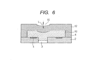
- the amount of falling-in toward the side of the supply path 3 at a position of the opening of the supply path 3 of an upper surface of the second photosensitive resin composition layer 12 which lies in an even plane in a region which does not correspond to a position of the supply path 3 was regarded as a falling-in amount (L).
- a laser microscope manufactured by KEYENCE CORPORATION
- the correlation between the falling-in amount (L) and printing quality was confirmed.
- the printing quality was good in a range of 0.5 to 1.5 ⁇ m when the falling-in amount is 0.5 ⁇ m or more which can be accurately measured.
- an ink droplet was not discharged in a desired direction when the falling-in amount exceeds 1.5 ⁇ m, and so the printing quality was lowered.
- a falling-in amount (L) of less than 0.5 ⁇ m was difficult to accurately measure, but the printing quality was good.
- the evaluation criterion regarding the falling-in amount (L) was determined as shown in Table 7 to evaluate the liquid discharge heads of the respective Examples and the respective Comparative Examples. Results thereof are shown in Tables 1, 2, 4 and 6.
- each liquid discharge head prepared was observed at a magnification of 100 times through a light microscope (manufactured by Nikon Corporation) for the purpose of examining pattering accuracy upon the patterning of the photosensitive resin composition layers, so as to confirm whether the ink seeks into the flow path forming member 4 or not.
- unevenness of pattern side walls of the flow path forming member 4 was observed at a magnification of 5,000 times through a scanning electron microscope (SEM, manufactured by Hitachi, Ltd.).
- SEM scanning electron microscope
Landscapes
- Physics & Mathematics (AREA)
- Engineering & Computer Science (AREA)
- General Physics & Mathematics (AREA)
- Manufacturing & Machinery (AREA)
- Spectroscopy & Molecular Physics (AREA)
- Architecture (AREA)
- Structural Engineering (AREA)
- Materials For Photolithography (AREA)
- Particle Formation And Scattering Control In Inkjet Printers (AREA)
Abstract
Description
- The present invention relates to a production process for an optically shaped product and a production process for a liquid discharge head using this production process.
- As an example of an optically shaped product, a liquid discharge head discharging a liquid may be mentioned. The liquid discharge head is used for discharging an ink in an ink jet recording apparatus as, for example, an ink jet recording head. The liquid discharge head applied to the ink jet recording generally includes plural fine discharge ports, flow paths respectively communicating with the discharge ports and discharge energy generating elements each provided at a part of the flow path for generating energy for discharging a liquid within the flow path. As a production process for such a liquid discharge head, a process of laminating a low-sensitive photosensitive resin layer forming a flow path and a high-sensitive photosensitive resin layer which will become a discharge port by patterning on a substrate in which a discharge energy generating element has been provided in advance is known. The low-sensitive photosensitive resin layer and the high-sensitive photosensitive resin layer are respectively cured, and uncured portions thereof are then removed, thereby forming the flow path and the discharge port on the substrate.
- In the production process for an ink jet recording head disclosed in Japanese Patent Application Laid-Open No.
2009-1003 - According to the present invention, there is provided a production process for an optically shaped product, which comprises applying a photosensitive resin composition in a form of a dry film on to a substrate in which a hole opening to a surface thereof is formed so as to cover the hole and performing patterning to form an optically shaped product, wherein the photosensitive resin composition contains a resin comprising a tri- or higher functional epoxy resin and a bifunctional epoxy resin, the bifunctional epoxy resin has a weight-average molecular weight (Mw) of 5,500 to 60,000, the resin has a weight-average molecular weight (Mw) ranging from 4,500 to 11,000, and a mixing ratio by mass between the tri- or higher functional epoxy resin and the bifunctional epoxy resin satisfies (b)/(a) ≤ 1.5, where (a) is a mass of the tri- or higher functional epoxy resin, and (b) is a mass of the bifunctional epoxy resin.
- According to the present invention, there is also provided a production process for a liquid discharge head, which comprises applying a photosensitive resin composition in a form of a dry film on to a substrate in which a discharge energy generating element and a liquid supply path for liquid are formed, wherein the photosensitive resin composition contains a resin comprising a tri- or higher functional epoxy resin and a bifunctional epoxy resin, the bifunctional epoxy resin has a weight-average molecular weight (Mw) of 5,500 to 60,000, the resin has a weight-average molecular weight (Mw) ranging from 4,500 to 11,000, and a mixing ratio by mass between the tri- or higher functional epoxy resin and the bifunctional epoxy resin satisfies (b)/(a) ≤ 1.5, where (a) is a mass of the tri- or higher functional epoxy resin, and (b) is a mass of the bifunctional epoxy resin.
- Further features of the present invention will become apparent from the following description of exemplary embodiments with reference to the attached drawings.
-
-
FIG. 1A is a schematic perspective view illustrating an example of the construction of a liquid discharge head, andFIG. 1B is a schematic sectional view taken alongline 1B-1B inFIG. 1A . -
FIGS. 2A, 2B, 2C, 2D and 2E are schematic sectional views illustrating an example of steps for producing the liquid discharge head illustrated inFIGS. 1A and 1B in order. -
FIGS. 3A, 3B and 3C are all plan views illustrating a shape of a discharge port. -
FIGS. 4A, 4B, 4C, 4D and 4E are schematic sectional views illustrating another example of steps for producing a liquid discharge head in order. -
FIGS. 5A, 5B, 5C, 5D and 5E are schematic sectional views illustrating steps for producing a liquid discharge head in Examples in order. -
FIG. 6 is a schematic sectional view illustrating falling-in of a photosensitive resin composition layer at a position of a supply path. - Preferred embodiments of the present invention will now be described in detail in accordance with the accompanying drawings.
- In the production process for the ink jet recording head described in Japanese Patent Application Laid-Open No.
2009-1003 - It is an object of the present invention to provide a production process for an optically shaped product, by which falling-in of a photosensitive resin layer into a recessed portion or a through-hole is small upon the formation of the optically shaped product by using a substrate having the recessed portion or the through-hole, and the height of the photosensitive resin layer after curing is controlled.
- Another object of the present invention is to provide a production process for a liquid discharge head by laminating a photosensitive resin layer on a substrate in which a supply path is formed in advance, by which falling-in of the photosensitive resin layer into the supply path is small, and a flow path height and a discharge port height can be made even.
- Preferred embodiments of the present invention will now be described in detail in accordance with the accompanying drawings. A case where a production process for an optically shaped product based on the present invention is applied to the production of a liquid discharge head will hereinafter be described as an example. However, the production process for the optically shaped product according to the present invention is not limited to the application to the production of the liquid discharge head.
-
FIG. 1A is a schematic perspective view illustrating a liquid discharge head produced according to a production process of this embodiment, andFIG. 1B is a schematic sectional view taken alongline 1B-1B inFIG. 1A and illustrates a sectional construction at a surface perpendicular to a substrate. This liquid discharge head has asubstrate 2 in which a plurality of dischargeenergy generating elements 1 for generating energy utilized for discharging a liquid are formed at predetermined pitches. Asupply path 3 for liquid is provided as a through-hole in thesubstrate 2. Side walls of aflow path 5 are formed on one surface of thesubstrate 2 by a flowpath forming member 4, and a dischargeport forming member 8 in which adischarge port 6 is provided as a through-hole is formed on the flowpath forming member 4 and theflow path 5. In addition, a water-repellent layer 9 is formed on the dischargeport forming member 8 as needed. This liquid discharge head discharges a liquid supplied through theflow path 5 from thesupply path 3 as a droplet from thedischarge port 6 by applying a pressure generated by the dischargeenergy generating element 1 to the liquid. - A production process for the liquid discharge head illustrated in
FIGS. 1A and 1B will now be described.FIGS. 2A to 2E are schematic sectional views illustrating steps for producing the liquid discharge head in this embodiment in order.FIG. 2E illustrates a view viewed at the same sectional position asFIG. 1B , which illustrates a state of completion. In this embodiment, two kinds of photosensitive resin compositions of a photosensitive resin composition (1) and a photosensitive resin composition (2) are used as described below. These photosensitive resin compositions are different in sensitivity to light used for patterning, and the photosensitive resin composition (2) has sensitivity higher than the photosensitive resin composition (1). Here, the sensitivity means an amount of exposure which is necessary for curing the photosensitive resin compositions, and the photosensitive resin composition with higher sensitivity is cured with a smaller amount of exposure. - After the photosensitive resin composition (1) is first applied on to a film substrate composed of polyethylene terephthalate (PET) or polyimide, the photosensitive resin composition (1) is transferred on to a
substrate 2 in which a dischargeenergy generating element 1 is arranged by means of a laminating method, thereby forming a film. A first photosensitiveresin composition layer 10 composed of an uncured photosensitive resin composition (1) is thereby formed on thesubstrate 2 as illustrated inFIG. 2A . Asupply path 3 is provided in thesubstrate 2, and thesupply path 3 forms a hole opening to surfaces of thesubstrate 2. The first photosensitiveresin composition layer 10 is formed so as to cover this hole and applied in a form of a dry film to the surface of thesubstrate 2. The photosensitive resin composition (1) constituting the first photosensitiveresin composition layer 10 is a negative photosensitive epoxy resin composition containing a resin comprising a tri- or higher functional epoxy resin (a) and a bifunctional epoxy resin (b). The composition thereof will be described in detail below. - The first photosensitive
resin composition layer 10 is then subjected to pattern exposure through a flowpath forming mask 11 having a flow path pattern, and the exposed portion is cured by additionally conducting a heat treatment (post exposure bake) to form a flowpath forming member 4 as illustrated inFIG. 2B . The unexposed portion remains as an uncured first photosensitiveresin composition layer 10. The flowpath forming mask 11 is a photomask and is obtained by forming alight shielding film 11A such as a chromium film according to a pattern such as a flow path on a substrate composed of a material such as glass or quartz transmitting light of an exposure wavelength. As an exposure apparatus, a light source of a single wavelength, such as an i-line exposure stepper or a KrF stepper, or a projection exposure apparatus having a light source of a broad wavelength of a mercury lamp, such as Mask Aligner MPA-600 Super (trade name, manufactured by Canon Inc.), may be used. - The photosensitive resin composition (2) is then applied on to a film substrate composed of PET or polyimide to form a film. Thereafter, the photosensitive resin composition (2) is transferred in a form of a dry film on to the first photosensitive
resin composition layer 10 and the flowpath forming member 4 by means of a laminating method to form a second photosensitiveresin composition layer 12. Accordingly, the photosensitive resin composition (2) is laminated in a form of a dry film on the photosensitive resin composition (1). A water-repellent layer 9 is additionally formed on the second photosensitiveresin composition layer 12 as needed as illustrated inFIG. 2C . An epoxy-resin-based negative epoxy resin composition is suitably used as the photosensitive resin composition (2). The composition thereof will be described in detail below. - The water-
repellent layer 9 is required to have repellency with respect to a liquid discharged from the liquid discharge head. A perfluoroalkyl composition or perfluoropolyether composition having cationic polymerizability is suitably used as the water-repellent layer 9. The perfluoroalkyl composition or perfluoropolyether composition is generally known to segregate a fluorinated alkyl chain at an interface between the composition and air by a bake treatment after the application thereof. The water-repellency of the surface of the composition can be enhanced by this segregated fluorinated alkyl chain. - The second photosensitive
resin composition layer 12 and the water-repellent layer 9 are then subjected to pattern exposure through a dischargeport forming mask 13 having a discharge port pattern, and the exposed portion is cured by additionally conducting a heat treatment (post exposure bake) to form a dischargeport forming member 8 as illustrated inFIG. 2D . At this time, when the exposure is conducted with light of a single wavelength, it is necessary to set the amount of exposure for curing the second photosensitiveresin composition layer 12 smaller than the amount of exposure used for curing the first photosensitiveresin composition layer 10. If the quantity of light transmitted through the second photosensitiveresin composition layer 12 is the amount of exposure for curing the first photosensitiveresin composition layer 10 when this second photosensitiveresin composition layer 12 is exposed, it is difficult to remove an unexposed portion of the first photosensitiveresin composition layer 10 in a subsequent step. As a result, theflow path 5 cannot be formed. For this reason, the photosensitive resin composition (2) requires to have relatively higher sensitivity regarding the exposure than the photosensitive resin composition (1). - The discharge
port forming mask 13 is obtained by forming alight shielding film 13A such as a chromium film according to a pattern such as a discharge port on a substrate composed of a material such as glass or quartz transmitting light of an exposure wavelength. The same apparatus as that used in the exposure of the first photosensitiveresin composition layer 10 may be used as an exposure apparatus. In addition, the discharge port pattern, i.e. the plane shape of the discharge port, may not always be circular and may be suitably determined in view of, for example, discharge characteristics, including the shapes illustrated inFIGS. 3A to 3C. FIG. 3A illustrates a discharge port of an elliptical shape, andFIG. 3B illustrates a discharge port formed of an elongated opening whose both ends are formed into a semicircle. In particular,FIG. 3C illustrates a circular discharge port in which a pair ofprojections 14 toward a central portion thereof is provided. A discharge port of such a shape as illustrated inFIG. 3C is used, whereby a liquid can be held between theprojections 14, thereby greatly reducing the situation that a droplet is divided into plural portions (main droplet and satellite) when the droplet is discharged. Accordingly, when the discharge port having the plane shape as illustrated inFIG. 3C is used in the case where the liquid discharge head is an ink jet recording head, printing of a high-quality image can be realized. - Unexposed portions of the first photosensitive
resin composition layer 10, the second photosensitiveresin composition layer 12 and the water-repellent layer 9 are collectively removed with an organic solvent to form aflow path 5 and adischarge port 6 as illustrated inFIG. 2E , and a heat treatment is then conducted as needed to complete a liquid discharge head. - In the production process for the liquid discharge head as described above, the second photosensitive
resin composition layer 12 is laminated after the first photosensitiveresin composition layer 10 is exposed. However, the second photosensitiveresin composition layer 12 may be laminated before the first photosensitiveresin composition layer 10 is exposed. Production steps in the case where the second photosensitiveresin composition layer 12 is laminated before the first photosensitiveresin composition layer 10 is exposed will now be described.FIGS. 4A to 4E are schematic sectional views illustrating steps for producing a liquid discharge head in this case in order.FIG. 4E illustrates a view viewed at the same sectional position asFIG. 1B , which illustrates a state of completion. - After the same photosensitive resin composition (1) as that described above is first applied on to a film substrate composed of PET or polyimide, the photosensitive resin composition (1) is transferred on to a
substrate 2 in which a dischargeenergy generating element 1 is arranged by means of a laminating method, thereby forming a film. Asupply path 3 forming a hole opening to surfaces of thesubstrate 2 is provided in thesubstrate 2, and this hole is covered with the first photosensitive resin composition (1). A first photosensitiveresin composition layer 10 composed of an uncured photosensitive resin composition (1) is thereby formed on thesubstrate 2 as illustrated inFIG. 4A . After the same photosensitive resin composition (2) as that described above is then applied on to a film substrate composed of PET or polyimide, the photosensitive resin composition (2) is transferred and laminated on the first photosensitiveresin composition layer 10 by means of a laminating method to form a second photosensitiveresin composition layer 12. In addition, a water-repellent layer 9 is formed on the second photosensitiveresin composition layer 12 as needed as illustrated inFIG. 4B . - The first photosensitive
resin composition layer 10 and the second photosensitiveresin composition layer 12 are then subjected to pattern exposure through a flowpath forming mask 11 having a flow path pattern, and a heat treatment is additionally conducted to cure exposed portions. As a result, as illustrated inFIG. 4C , a flowpath forming member 4 which will become side walls of a flow path is formed, and moreover a part of a dischargeport forming member 8 is formed. The second photosensitiveresin composition layer 12 and the water-repellent layer 9 are then subjected to pattern exposure through a dischargeport forming mask 13 having a discharge port pattern as illustrated inFIG. 4D . A heat treatment is additionally conducted to cure exposed portions, thereby forming the dischargeport forming member 8 in such a manner that only a position where a discharge port is to be formed becomes an uncured portion. - Uncured portions of the first photosensitive
resin composition layer 10, the second photosensitiveresin composition layer 12 and the water-repellent layer 9 are collectively removed with an organic solvent to form aflow path 5 and adischarge port 6 as illustrated inFIG. 4E , and a heat treatment is conducted as needed to complete a liquid discharge head. - Even in the production process illustrated in
FIGS. 4A to 4E , the photosensitive resin composition (2) forming the second photosensitiveresin composition layer 12 requires to have relatively higher sensitivity regarding the exposure than the photosensitive resin composition (1) forming the first photosensitiveresin composition layer 10. In addition, the exposure of the discharge port pattern may be conducted before the exposure of the flow path pattern. - The respective photosensitive resin compositions used in this embodiment will now be described. Photosensitive resin composition (1):
- The photosensitive resin composition (1) forming the first photosensitive
resin composition layer 10 is a negative photosensitive epoxy resin composition containing a resin comprising a tri- or higher functional epoxy resin (a) and a bifunctional epoxy resin (b). In addition, this composition favorably contains a photoacid generator. A cured product of the photosensitive resin composition (1) is required to have mechanical strength and adhesion to a substrate. In addition, the photosensitive resin composition (1) needs to be selected in view of resolution as a photolithographic material. Since a layer formed of the photosensitive resin composition (1) is formed in a form of a dry film on a substrate having a recessed portion or through-hole which will become an opening at a surface, the photosensitive resin composition (1) requires to have such a film strength that the layer is not deformed even in an uncured state upon transfer or another heat step. This embodiment intends to obtain an optically shaped product in which the height of the photosensitive resin layer after curing is controlled by covering a hole with a photosensitive resin composition having such a film strength that the layer is not deformed even in an uncured state. - The photosensitive resin composition (1) contains a resin having a trivalent or higher polyvalent epoxy group as a trivalent or higher polyfunctional epoxy resin (a), whereby crosslinking is caused to three-dimensionally proceed to improve sensitivity as a photosensitive material. The tri- or higher functional epoxy resin (a) favorably has an epoxy equivalent less than 500 and a softening point of 60°C or higher though no particular limitation is imposed on them. When the epoxy equivalent is 500 or higher, the sensitivity of the resulting resin composition becomes insufficient, so that the lowering of pattern resolution or the lowering of mechanical strength or adhesion of a cured product may be caused in some cases. In addition, when the softening point is less than 60°C, the photosensitive resin composition (1) applied on to the film substrate for forming a dry film may be softened in a production apparatus in some cases, which forms the cause of wrinkling upon formation of the first photosensitive resin composition layer by transferring the photosensitive resin composition (1) to the substrate. As examples of the tri-or higher functional epoxy resin having such favorable properties, there may be mentioned a phenol-novolak type epoxy resin, a cresol- novolak type epoxy resin, a bisphenol A-novolak type epoxy resin and a tri- or higher functional epoxy resin having an oxycyclohexane skeleton. As commercially available epoxy resins, there are mentioned "EHPE (trademark) 3150" (product of Daicel Corporation), "jER (trademark) 157S70" and "jER (trademark) 1031S" (products of Mitsubishi Chemical Corporation), and "EPICLON (trademark) N-865" and "EPICLON (trademark) N-690" (products of DIC Corporation).
- Incidentally, the softening point in the present specification means a softening point measured by the ring and ball method specified in JIS K 7234.
- The bifunctional epoxy resin (b) contained in the photosensitive resin composition (1) is used as a binder for improving the film strength of the photosensitive resin composition (1) and is desired to have a weight-average molecular weight higher than that of the tri- or higher functional epoxy resin. Specifically, the bifunctional epoxy resin (b) desirably has a weight-average molecular weight (Mw) of 5,500 to 60,000 and a softening point of 90°C or more. If the weight-average molecular weight is less than 5,500, the film strength is not improved, and so the photosensitive resin composition (1) and the photosensitive resin composition (2) formed into respective films may greatly fall in the opening of the substrate in some cases upon the transfer of the photosensitive resin composition (2) on to the photosensitive resin composition (1) or upon another thermal process. When the photosensitive resin composition (1) and the photosensitive resin composition (2) greatly fall in the opening, the heights of the respective photosensitive resin composition layers become uneven. Even if the softening point is less than 90°C, the same falling-in problem may occur in some cases. If the weight-average molecular weight (Mw) is more than 60,000 on the other hand, the crosslinking density of the photosensitive resin composition (1) is lowered, and so the stability of its pattern shape is lowered. The bifunctional epoxy resin having desired properties as described above is favorably an epoxy resin having a bisphenol skeleton, particularly favorably an epoxy resin having a bisphenol A skeleton. Examples of commercially available epoxy resins include "jER (trademark) 1004", "jER (trademark) 1007", "jER (trademark) 1009", "jER (trademark) 1010" and "jER (trademark) 1256" (products of Mitsubishi Chemical Corporation), and "EPICLON (trademark) 4050" and "EPICLON (trademark) 7050" (products of DIC Corporation). The weight-average molecular weights (Mw) of these resins can be calculated in terms of polystyrene by means of a gel permeation chromatograph (manufactured by, for example Shimadzu Corporation).
- The mixing ratio between the tri- or higher functional epoxy resin (a) and the bifunctional epoxy resin (b) satisfies (b)/(a) ≤ 1.5 in terms of mixing ratio by mass, and the weight-average molecular weight (Mw) of the photosensitive resin composition (1) falls within a range of 4,500 to 11,000. In the expression indicating the mixing ratio by mass in the present specification, "(a)" is the mass of the tri- or higher functional epoxy resin (a), and "(b)" is the mass of the bifunctional epoxy resin (b). The bifunctional epoxy resin (b) is high in epoxy equivalent and low in reactivity compared with the tri- or higher functional epoxy resin (a). Accordingly, if the mixing ratio by mass is higher than 1.5, i.e., (b)/(a) > 1.5, the crosslinking density of the resulting photosensitive resin composition (1) is lowered, curing thereof becomes insufficient, and pattern accuracy is lowered. If the stability of the pattern shape is lowered, irregularity cay be caused on side walls of the pattern, and so the pattern may not be formed with desired accuracy in some cases. As a result, insufficient curing or lowering of the stability of the pattern shape may cause the lowering of adhesion between the photosensitive resin composition (1) and the substrate in some cases. On the other hand, if the weight-average molecular weight (Mw) of the photosensitive resin composition (1) is more than 11,000 even when the mixing ratio by mass (b)/(a) is 1.5 or less, the crosslinking density is lowered to cause the same problem. If the weight-average molecular weight (Mw) of the photosensitive resin composition (1) is less than 11,000 on the other hand, the film strength of the photosensitive resin composition (1) becomes insufficient, and the falling-in at the opening of the substrate occurs.
- The photoacid generator is favorably a sulfonic acid compound, a solfonium salt compound, an iodonium salt compound, a disulfone-based compound or a phosphoric acid compound. Examples of commercially available products thereof include "ADEKA OPTOMER SP-170", "ADEKA OPTOMER SP-172" and "ADEKA OPTOMER SP-150" (all, trade names, products of ADEKA CORPORATION), "BBI-103" and "BBI-102" (both, trade names, products of Midori Kagaku Co., Ltd.), "IBPF", "IBCF", "TS-01" and "TS-91" (all, trade names, products of SANWA CHEMICAL CO., LTD.), "CPI-210", "CPI-300" and "CPI-410" (all, trade names, products of San-Apro Ltd.), and "Irgacure (trademark) 290" (product of BASF Japan Ltd.). These photoacid generators may also be used in any combination thereof. In addition, a silane coupling agent may also be added for the purpose of improving adhesion. Examples of commercially available silane coupling agents include "A-187" (trade name, product of Momentive Performance Materials Inc.). Further, a sensitizer such as an anthracene compound, a basic substance such as an amine or an acid generator generating toluenesulfonic acid which is weakly acidic (pKa = -1.5 to 3.0) may also be added for the purpose of improving pattern resolution and controlling sensitivity. Examples of commercially available acid generators which generate toluenesulfonic acid include "TPS-1000" (trade name, product of Midori Kagaku Co., Ltd.) and "WPAG-367" (trade name, product of Wako Pure Chemical industries, Ltd.). Photosensitive resin composition (2):
- The photosensitive resin composition (2) requires that its cured product has mechanical strength and further requires to take resolution as a photographic material into consideration. Therefore, a negative epoxy resin composition containing, as a main component, an epoxy resin such as a bisphenol A novolak type epoxy resin, a phenol novolak type epoxy resin, a cresol novolak type epoxy resin or a tri- or higher functional epoxy resin having an oxycyclohexane skeleton is suitably used as the photosensitive resin composition (2). The use of the epoxy resin having a tri- or higher valent epoxy group enables three-dimensionally crosslinking of the cured product, and is suitable for obtaining desired properties. Examples of commercially available epoxy resins usable in the photosensitive resin composition (2) include "CELLOXIDE (trademark) 2021", "GT-300 Series" and "GT-400 Series" (both, trade names) and "EHPE (trademark) 3150" (all, products of Daicel Corporation), "jER (trademark) 157S70" (product of Mitsubishi Chemical Corporation), and "EPICLON (trademark) N-690" and "EPICLON (trademark) N-865" (products of DIC Corporation). A photopolymerization initiator to be added into the above-described epoxy resin composition is favorably a sulfonic acid compound, a diazomethane compound, a solfonium salt compound, an iodonium salt compound or a disulfone-based compound. Examples of commercially available products thereof include "ADEKA OPTOMER SP-170", "ADEKA OPTOMER SP-172" and "ADEKA OPTOMER SP-150" (all, trade names, products of ADEKA CORPORATION), "BBI-103" and "BBI-102" (both, trade names, products of Midori Kagaku Co., Ltd.), "IBPF", "IBCF", "TS-01" and "TS-91" (all, trade names, products of SANWA CHEMICAL CO., LTD.), "CPI-210", "CPI-300" and "CPI-410" (all, trade names, products of San-Apro Ltd.), and "Irgacure (trademark) 290" (product of BASF Japan Ltd.). In addition, a silane coupling agent may also be added into the photosensitive resin composition (2) for the purpose of improving adhesion. Examples of commercially available silane coupling agents include "A-187" (trade name, product of Momentive Performance Materials Inc.). Further, a sensitizer such as an anthracene compound, a basic substance such as an amine and an acid generator which generates toluenesulfonic acid and is weakly acidic (pKa = -1.5 to 3.0) may also be added for the purpose of improving pattern resolution and controlling sensitivity. Examples of commercially available acid generators which generate toluenesulfonic acid include "TPS-1000" (trade name, product of Midori Kagaku Co., Ltd.) and "WPAG-367" (trade name, product of Wako Pure Chemical industries, Ltd.).
- Further, "SU-8 Series" (trade name) and "KMPR (trademark) 1000" (products of MicroChem Corp.), and "TMMR (trademark) S2000" and "TMMF (trademark) S2000" (products of TOKYO OHKA KOGYO CO., LTD.) which are commercially available as negative resists may also be used for the photosensitive resin composition (2).
- The present invention will hereinafter be described in more detail by the following Examples. However, the present invention is not limited to these Examples.
- In respective Examples, photosensitive resin compositions (1) were prepared according to their corresponding compositions shown in Tables 1 and 2. Incidentally, in both Tables, the compositions are indicated by parts by mass, and the product names in both Tables conform to the trade names of the epoxy resins and chemicals mentioned above as favorably usable products. In addition, polyethylene glycol monomethacrylate (PEGMA) was used as a solvent dissolving the photosensitive resin composition. A photoacid generator (CPI-210S) was added at a proportion of 0.5% by mass to the total mass of a tri- or higher functional epoxy resin (a) and a bifunctional epoxy resin (b). In addition, a silane coupling agent was added at a proportion of 5% by mass to the same total mass. The weight-average molecular weights (Mw) shown in both Tables are values in terms of polystyrene as measured by means of a gel permeation chromatograph (manufactured by Shimadzu Corporation). A liquid discharge head using each of the photosensitive resin compositions of the above-described compositions was prepared according to the steps illustrated in
FIGS. 5A to 5E . The steps illustrated inFIGS. 5A to 5E are the same as those illustrated inFIGS. 2A to 2E , but are different from those illustrated inFIGS. 2A to 2E in that no water-repellent layer is provided. - First, the photosensitive resin composition (1) was applied on to a PET film having a thickness of 100 µm and baked for 5 minutes at 90°C to evaporate the PEGMA solvent and form a film having a thickness of 15 µm. Then, the film of the photosensitive resin composition (1) was transferred to a
substrate 2 in which a dischargeenergy generating element 1 and asupply path 3 have been provided in advance in a form of a dry film while applying heat of 80°C by means of a laminating method. Thesupply path 3 of thesubstrate 2 is a hole opening to surfaces of thesubstrate 2, and this hole was covered with the photosensitive resin composition (1). A first photosensitiveresin composition layer 10 was formed as illustrated inFIG. 5A . As illustrated inFIG. 5B , the first photosensitiveresin composition layer 10 was then subjected to pattern exposure in an amount of exposure of 9,000 J/m2 by means of an i-line exposure stepper through a flowpath forming mask 11 having a flow path pattern. The exposed portion was cured by additionally conducting a heat treatment for 5 minutes at 50°C to form a flowpath forming member 4. - A photosensitive resin composition (2) shown in Table 3 was then applied on to a PET film having a thickness of 100 µm and baked for 5 minutes at 90°C to form a film having a thickness of 10 µm. As illustrated in
FIG. 5C , the film of the photosensitive resin composition (2) was then transferred and laminated on the first photosensitiveresin composition layer 10 and the flowpath forming member 4 while applying heat of 50°C by means of a laminating method, thereby forming a second photosensitiveresin composition layer 12. As illustrated inFIG. 5D , the second photosensitiveresin composition layer 12 was then subjected to pattern exposure in an amount of exposure of 600 J/m2 by means of an i-line exposure stepper through a dischargeport forming mask 13 having a discharge port pattern. The exposed portion was cured by additionally conducting a heat treatment for 5 minutes at 90°C to form a dischargeport forming member 8. Unexposed portions of the first photosensitiveresin composition layer 10 and the second photosensitiveresin composition layer 12 were then collectively removed with the PGMEA solvent to form aflow path 5 and adischarge port 6. Curing was additionally conducted with heat of 200°C to obtain a liquid discharge head as illustrated inFIG. 5E .Table 1 Product name Molecular weight (Mw) Example 1 2 3 4 5 6 7 8 9 10 11 12 Tri- or higher functional epoxy resin (a) EPICLON N695 3400 100 100 100 100 100 100 100 100 100 100 100 100 Bifunctional epoxy resin (b) jER1004 5560 110 150 - - - - - - - - - - jER1007 11200 - - 20 30 50 90 150 - - - - - jER1009 22700 - - - - - - - 10 20 50 - - jER1256 58000 - - - - - - - - - - 5 15 Photoacid generator CPI-210S - 1.1 1.3 0.6 0.7 0.8 1.0 1.3 0.6 0.6 0.8 0.5 0.6 Silane coupling agent A-187 - 10.5 12.5 6.0 6.5 7.5 9.5 12.5 5.5 6.0 7.5 5.3 5.8 Solvent PGMEA - 252 300 144 156 180 228 300 132 144 180 126 138 Molecular weight of mixed resin (Mw) 4520 4680 4670 5170 5970 7070 8050 5130 6590 9810 5970 10500 Mixing ratio by mass (b)/(a) 1.1 1.5 0.2 0.3 0.5 0.9 1.5 0.1 0.2 0.5 0.1 0.2 Amount of exposure [J/m2] 9000 9000 9000 9000 9000 9000 9000 9000 9000 9000 9000 9000 Falling-in amount (L) B B B A A A A B A A A A Pattern shape A A A A A A B A A B B B Table 2 Product name Molecular weight (Mw) Example 13 14 15 16 17 18 19 20 21 Tri- or higher functional epoxy resin (a) jER157S70 3300 100 100 100 100 100 - - - - EHPE-3150 2500 - - - - - 100 100 100 100 Bifunctional epoxy resin (b) jER1007 11200 20 30 50 90 150 30 50 90 150 Photoacid generator CPI-210S - 0.6 0.7 0.8 1.0 1.3 0.7 0.8 1.0 1.3 Silane coupling agent A-187 - 6.0 6.5 7.5 9.5 12.5 6.5 7.5 9.5 12.5 Solvent PGMEA - 144 156 180 228 300 156 180 228 300 Molecular weight of mixed resin (Mw) 4610 5120 5930 7030 8030 4500 5390 6610 7710 Mixing ratio by mass (b)/(a) 0.2 0.3 0.5 0.9 1.5 0.3 0.5 0.9 1.5 Amount of exposure [J/m2] 9000 9000 9000 9000 9000 9000 9000 9000 9000 Falling-in amount (L) B A A A A B A A A Pattern shape A A A A B A A A B Table 3 Product name Mass ratio Tri- or higher functional epoxy resin EHPE-3150 100 Photoacid generator Irgacure 290 1.0 Silane coupling agent A-187 5.0 Solvent PGMEA 120 - In respective Examples, PEGMA was used as a solvent to prepare photosensitive resin compositions (1) according to their corresponding compositions shown in Table 4. Proper amounts of two kinds of photoacid generators which were different in sensitivity and an acid generator (TPS-1000) were added into the photosensitive resin compositions (1). In addition, a silane coupling agent (A-187) was added in an amount of 5% by mass to the total mass of a tri- or higher functional epoxy resin (a) and a bifunctional epoxy resin (b). The composition of a photosensitive resin composition (2) was as shown in Table 5. These photosensitive resin compositions (1) and the photosensitive resin composition (2) were used to obtain liquid discharge heads according to the same production process as in Example 1. At this time, the amount of exposure to the first photosensitive
resin composition layer 10 formed of the photosensitive resin composition (1) was controlled as shown in Table 4, and the amount of exposure to the second photosensitiveresin composition layer 12 formed of the photosensitive resin composition (2) was controlled to 1,200 J/m2.Table 4 Product name Molecular weight (Mw) Example 22 23 24 25 26 28 29 Tri- or higher functional epoxy resin (a) EPICLON N695 3400 100 100 100 100 100 100 100 Bifunctional epoxy resin (b) jER1007 11200 50 50 50 50 50 - - jER1009 22700 - - - - - 20 20 Photoacid generator CPI-410S - 1.5 1.5 1.5 1.5 1.0 1.2 1.2 SP-172 4.8 4.8 4.8 - - 5.8 5.8 CPI-300 - - - 5.4 3.6 - - Acid generator TPS-1000 0.30 0.45 0.53 0.45 0.30 0.29 0.38 Silane coupling agent A-187 - 7.5 7.5 7.5 7.5 7.5 6.0 6.0 Solvent PGMEA - 180 180 180 180 180 144 144 Molecular weight of mixed resin (Mw) 5970 5970 5970 5970 5970 6590 6590 Mixing ratio by mass (b)/(a) 0.5 0.5 0.5 0.5 0.5 0.2 0.2 Amount of exposure [J/m2] 3000 5000 7000 5000 5000 5000 7000 Falling-in amount (L) A A A A A A A Pattern shape A A A A A A A Table 5 Product name Mass ratio Tri- or higher functional epoxy resin jER157S70 100 Photoacid generator CPI-410S 0.7 Silane coupling agent A-187 5.0 Solvent PGMEA 120 - In respective Examples, PEGMA was used as a solvent to prepare photosensitive resin compositions (1) according to their corresponding compositions shown in Table 6, and liquid discharge heads were obtained according to the same production process as in Example 1. The composition of the photosensitive resin composition (2) was the same as Example 1, and amounts of exposure to the respective photosensitive resin composition layers were also be the same as Example 1.
Table 6 Product name Molecular weight (Mw) Example 1 2 3 4 5 6 7 8 Tri- or higher functional epoxy resin (a) EPICLON N695 3400 100 100 100 100 100 100 100 100 Bifunctional epoxy resin (b) jER1004 5560 - 50 200 - - - - - jER1007 11200 - - - 10 180 - - - jER1009 22700 - - - - - 5 80 - jER1256 58000 - - - - - - - 25 Photoacid generator CPI-210S - 0.5 0.8 1.5 0.6 1.4 0.5 0.9 0.6 Silane coupling agent A-187 - 5.0 7.5 15.0 5.5 14.0 5.3 9.0 6.3 Molecular weight of mixed resin (Mw) 3370 4100 4830 4080 8390 4290 11960 14290 Mixing ratio by mass (b)/(a) 0.0 0.5 2.0 0.1 1.8 0.1 0.8 0.3 Amount of exposure [J/m2] 9000 9000 9000 9000 9000 9000 9000 9000 Falling-in amount (L) C C A C A C A A Pattern shape A A C A C A C C - An ink composed of ethylene glycol/urea/ isopropylalcohol/N-methylpyrrolidone/black dye/water at a mass ratio of 5/3/2/5/3/82 was filled into each of the liquid discharge heads prepared in Examples 1 to 29 and Comparative Examples 1 to 8 to conduct printing. In addition, a falling-in amount (L) which is a depth of falling-in of the photosensitive resin composition layer above the
supply path 3 was measured after the lamination of the photosensitiveresin composition layer 12 formed of the photosensitive resin composition (2) in the production process of each liquid discharge head. As illustrated inFIG. 6 , the amount of falling-in toward the side of thesupply path 3 at a position of the opening of thesupply path 3 of an upper surface of the second photosensitiveresin composition layer 12 which lies in an even plane in a region which does not correspond to a position of thesupply path 3 was regarded as a falling-in amount (L). A laser microscope (manufactured by KEYENCE CORPORATION) was used to measure a depth from an even surface of the second photosensitiveresin composition layer 12 to the deepest portion of the falling-in, and the depth was regarded as the falling-in amount (L). In addition, the correlation between the falling-in amount (L) and printing quality was confirmed. As a result, the printing quality was good in a range of 0.5 to 1.5 µm when the falling-in amount is 0.5 µm or more which can be accurately measured. However, an ink droplet was not discharged in a desired direction when the falling-in amount exceeds 1.5 µm, and so the printing quality was lowered. A falling-in amount (L) of less than 0.5 µm was difficult to accurately measure, but the printing quality was good. Thus, the evaluation criterion regarding the falling-in amount (L) was determined as shown in Table 7 to evaluate the liquid discharge heads of the respective Examples and the respective Comparative Examples. Results thereof are shown in Tables 1, 2, 4 and 6. - The
flow path 5 of each liquid discharge head prepared was observed at a magnification of 100 times through a light microscope (manufactured by Nikon Corporation) for the purpose of examining pattering accuracy upon the patterning of the photosensitive resin composition layers, so as to confirm whether the ink seeks into the flowpath forming member 4 or not. In addition, unevenness of pattern side walls of the flowpath forming member 4 was observed at a magnification of 5,000 times through a scanning electron microscope (SEM, manufactured by Hitachi, Ltd.). The pattern shape was evaluated according to the evaluation criterion shown in Table 8 from these confirmation and observation results. Evaluation results of the pattern shape are shown in Tables 1, 2, 4 and 6.Table 7 Falling-in amount (L) Printing quality A Less than 0.5 µm Good B 0.5 µm to 1.5 Good C Exceeding 1.5 µm Lowered Table 8 Pattern shape Seeping of ink (light microscope) Pattern side walls (SEM) A Not occurred Good B Not occurred Irregularity C Occurred Irregularity - While the present invention has been described with reference to exemplary embodiments, it is to be understood that the invention is not limited to the disclosed exemplary embodiments. The scope of the following claims is to be accorded the broadest interpretation so as to encompass all such modifications and equivalent structures and functions.
Claims (13)
- A production process for an optically shaped product, comprising applying a photosensitive resin composition in a form of a dry film on to a substrate in which a hole opening to a surface thereof is formed so as to cover the hole and performing patterning to form an optically shaped product, wherein the photosensitive resin composition contains a resin comprising a tri- or higher functional epoxy resin and a bifunctional epoxy resin, the bifunctional epoxy resin has a weight-average molecular weight (Mw) of 5,500 to 60,000, the resin has a weight-average molecular weight (Mw) ranging from 4,500 to 11,000, and a mixing ratio by mass between the tri- or higher functional epoxy resin and the bifunctional epoxy resin satisfies (b)/(a) ≤ 1.5, where (a) is a mass of the tri- or higher functional epoxy resin, and (b) is a mass of the bifunctional epoxy resin.
- The production process according to claim 1, wherein the bifunctional epoxy resin is an epoxy resin having a bisphenol skeleton.
- The production process according to claim 1 or 2, wherein the bifunctional epoxy resin has a softening point of 90°C or more.
- The production process according to any one of claims 1 to 3, wherein the photosensitive resin composition contains a photoacid generator.
- The production process according to any one of claims 1 to 4, wherein the photosensitive resin composition is formed of a first photosensitive resin composition (1), and a second photosensitive resin composition (2) is laminated on the first photosensitive resin composition (1) in a form of a dry film.
- The production process according to claim 5, wherein the second photosensitive resin composition (2) contains at least a tri- or higher functional epoxy resin and a photoacid generator.
- The production process according to any one of claims 1 to 4,
wherein the optically shaped product is a liquid discharge head, and
wherein a discharge energy generating element and, as the hole opening, a liquid supply path for liquid are formed in the substrate. - The production process according to claim 7, wherein the photosensitive resin composition is formed of a first photosensitive resin composition (1), and a second photosensitive resin composition (2) is laminated on the first photosensitive resin composition (1) in a form of a dry film.
- The production process according to claim 8, wherein a liquid flow path is formed by pattering the first photosensitive resin composition (1).
- The production process according to claim 8 or 9, wherein the second photosensitive resin composition (2) contains at least a tri- or higher functional epoxy resin and a photoacid generator.
- The production process according to any one of claims 8 to 10, wherein a discharge port for the liquid is formed by pattering the second photosensitive resin composition (2).
- The production process according to any one of claims 8 to 11, further comprising a step of collectively removing an uncured portion of the first photosensitive resin composition (1) and an uncured portion of the second photosensitive resin composition (2).
- The production process according to any one of claims 8 to 12, wherein an amount of exposure which is necessary for curing the second photosensitive resin composition (2) is smaller than an amount of exposure which is necessary for curing the first photosensitive resin composition (1).
Applications Claiming Priority (2)
| Application Number | Priority Date | Filing Date | Title |
|---|---|---|---|
| JP2014194701 | 2014-09-25 | ||
| JP2015130967A JP6635692B2 (en) | 2014-09-25 | 2015-06-30 | Method for manufacturing stereolithography and method for manufacturing liquid ejection head |
Publications (2)
| Publication Number | Publication Date |
|---|---|
| EP3001248A1 true EP3001248A1 (en) | 2016-03-30 |
| EP3001248B1 EP3001248B1 (en) | 2021-04-07 |
Family
ID=54145512
Family Applications (1)
| Application Number | Title | Priority Date | Filing Date |
|---|---|---|---|
| EP15002614.4A Active EP3001248B1 (en) | 2014-09-25 | 2015-09-07 | Production process for liquid discharge head |
Country Status (3)
| Country | Link |
|---|---|
| US (1) | US9599893B2 (en) |
| EP (1) | EP3001248B1 (en) |
| CN (1) | CN105467757B (en) |
Families Citing this family (5)
| Publication number | Priority date | Publication date | Assignee | Title |
|---|---|---|---|---|
| JP6552660B1 (en) * | 2018-02-28 | 2019-07-31 | キヤノン株式会社 | Manufacturing method of substrate for liquid discharge head |
| JP7134825B2 (en) * | 2018-10-05 | 2022-09-12 | キヤノン株式会社 | Microstructure manufacturing method and liquid ejection head manufacturing method |
| JP7297442B2 (en) * | 2018-12-27 | 2023-06-26 | キヤノン株式会社 | Microstructure manufacturing method and liquid ejection head manufacturing method |
| JP7672840B2 (en) * | 2021-02-26 | 2025-05-08 | キヤノン株式会社 | Manufacturing method of laminate and manufacturing method of liquid ejection head |
| JP7362698B2 (en) * | 2021-07-28 | 2023-10-17 | キヤノン株式会社 | Photosensitive resin composition, shaped article, method for producing shaped article, and method for producing liquid ejection head |
Citations (5)
| Publication number | Priority date | Publication date | Assignee | Title |
|---|---|---|---|---|
| EP0453581A1 (en) * | 1990-03-22 | 1991-10-30 | Canon Kabushiki Kaisha | Liquid jet recording head and recording apparatus having same |
| EP0931656A1 (en) * | 1998-01-26 | 1999-07-28 | Canon Kabushiki Kaisha | Method of producing an ink jet recording head and ink jet recording head |
| JP2009001003A (en) | 2007-06-21 | 2009-01-08 | Samsung Electronics Co Ltd | Inkjet printhead manufacturing method |
| US20100068648A1 (en) * | 2007-01-24 | 2010-03-18 | Tokyo Ohka Kogyo Co., Ltd. | Photosensitive resin composition, and resist pattern formation method using the same |
| EP2743286A1 (en) * | 2011-08-11 | 2014-06-18 | Goo Chemical Co., Ltd. | Resin composition for resists |
Family Cites Families (13)
| Publication number | Priority date | Publication date | Assignee | Title |
|---|---|---|---|---|
| JP2697937B2 (en) * | 1989-12-15 | 1998-01-19 | キヤノン株式会社 | Active energy ray-curable resin composition |
| US5578418A (en) * | 1990-03-21 | 1996-11-26 | Canon Kabushiki Kaisha | Liquid jet recording head and recording apparatus having same |
| US5859655A (en) * | 1995-10-30 | 1999-01-12 | International Business Machines Corporation | Photoresist for use in ink jet printers and other micro-machining applications |
| CN1849560B (en) * | 2004-03-26 | 2011-12-07 | 东京応化工业株式会社 | Photosensitive resin composition and pattern forming method using same |
| JP4593309B2 (en) * | 2005-01-21 | 2010-12-08 | 東京応化工業株式会社 | Method for forming a top plate in a precise fine space |
| US7571979B2 (en) * | 2005-09-30 | 2009-08-11 | Lexmark International, Inc. | Thick film layers and methods relating thereto |
| WO2007094396A1 (en) * | 2006-02-16 | 2007-08-23 | Tokyo Ohka Kogyo Co., Ltd. | Photosensitive resin composition and pattern forming method using same |
| US8273524B2 (en) | 2007-06-18 | 2012-09-25 | Canon Kabushiki Kaisha | Liquid discharging head, producing method thereof, structure, and producing method thereof |
| JP2009083106A (en) * | 2007-09-27 | 2009-04-23 | Fujifilm Corp | Plane surface protecting agent for lithographic printing plate and plate making method of lithographic printing plate |
| JP5854693B2 (en) * | 2010-09-01 | 2016-02-09 | キヤノン株式会社 | Method for manufacturing liquid discharge head |
| JP5546504B2 (en) * | 2011-07-14 | 2014-07-09 | キヤノン株式会社 | Manufacturing method of recording head |
| JP2013188916A (en) | 2012-03-13 | 2013-09-26 | Canon Inc | Method for manufacturing ink jet recording head |
| JP6112809B2 (en) * | 2012-09-21 | 2017-04-12 | キヤノン株式会社 | Method for manufacturing droplet discharge head |
-
2015
- 2015-08-18 US US14/828,736 patent/US9599893B2/en not_active Expired - Fee Related
- 2015-09-07 EP EP15002614.4A patent/EP3001248B1/en active Active
- 2015-09-25 CN CN201510623132.4A patent/CN105467757B/en not_active Expired - Fee Related
Patent Citations (5)
| Publication number | Priority date | Publication date | Assignee | Title |
|---|---|---|---|---|
| EP0453581A1 (en) * | 1990-03-22 | 1991-10-30 | Canon Kabushiki Kaisha | Liquid jet recording head and recording apparatus having same |
| EP0931656A1 (en) * | 1998-01-26 | 1999-07-28 | Canon Kabushiki Kaisha | Method of producing an ink jet recording head and ink jet recording head |
| US20100068648A1 (en) * | 2007-01-24 | 2010-03-18 | Tokyo Ohka Kogyo Co., Ltd. | Photosensitive resin composition, and resist pattern formation method using the same |
| JP2009001003A (en) | 2007-06-21 | 2009-01-08 | Samsung Electronics Co Ltd | Inkjet printhead manufacturing method |
| EP2743286A1 (en) * | 2011-08-11 | 2014-06-18 | Goo Chemical Co., Ltd. | Resin composition for resists |
Also Published As
| Publication number | Publication date |
|---|---|
| US20160091789A1 (en) | 2016-03-31 |
| CN105467757B (en) | 2019-11-22 |
| EP3001248B1 (en) | 2021-04-07 |
| CN105467757A (en) | 2016-04-06 |
| US9599893B2 (en) | 2017-03-21 |
Similar Documents
| Publication | Publication Date | Title |
|---|---|---|
| JP6635692B2 (en) | Method for manufacturing stereolithography and method for manufacturing liquid ejection head | |
| EP3001248B1 (en) | Production process for liquid discharge head | |
| JP7297442B2 (en) | Microstructure manufacturing method and liquid ejection head manufacturing method | |
| JP7413039B2 (en) | Liquid ejection head and method for manufacturing liquid ejection head | |
| US11305538B2 (en) | Method of manufacturing microstructure and method of manufacturing liquid ejection head | |
| US8703398B2 (en) | Method of manufacturing liquid ejection head | |
| US11426999B2 (en) | Liquid discharge head and method for producing liquid discharge head | |
| US20200009868A1 (en) | Method for manufacturing liquid ejection head and liquid ejection head | |
| JP2018051883A (en) | Liquid discharge head and manufacturing method for the same | |
| US10265960B2 (en) | Method for manufacturing liquid ejection head | |
| US20120105546A1 (en) | Inkjet head and method of manufacturing inkjet head | |
| JP2016095373A (en) | Method for manufacturing optically molded object, method for manufacturing liquid discharge head, and photosensitive resin composition | |
| US10363740B2 (en) | Liquid ejection head and method for manufacturing the same | |
| JP6333016B2 (en) | Method for manufacturing liquid discharge head | |
| US10189253B2 (en) | Liquid ejection head and method for producing the same | |
| JP2018114749A (en) | Liquid discharge head and method for manufacturing the same | |
| JP7672840B2 (en) | Manufacturing method of laminate and manufacturing method of liquid ejection head | |
| US20250135781A1 (en) | Liquid ejection head and method of producing liquid ejection head | |
| US20240310729A1 (en) | Method of producing microstructure and liquid ejection head | |
| JP4908816B2 (en) | Inkjet head manufacturing method | |
| JP2026028213A (en) | Photosensitive resin composition, liquid-repellent antifouling film, and ink-jet recording head | |
| CN121928868A (en) | Method for manufacturing liquid ejecting head and liquid ejecting head |
Legal Events
| Date | Code | Title | Description |
|---|---|---|---|
| PUAI | Public reference made under article 153(3) epc to a published international application that has entered the european phase |
Free format text: ORIGINAL CODE: 0009012 |
|
| AK | Designated contracting states |
Kind code of ref document: A1 Designated state(s): AL AT BE BG CH CY CZ DE DK EE ES FI FR GB GR HR HU IE IS IT LI LT LU LV MC MK MT NL NO PL PT RO RS SE SI SK SM TR |
|
| AX | Request for extension of the european patent |
Extension state: BA ME |
|
| 17P | Request for examination filed |
Effective date: 20160930 |
|
| RBV | Designated contracting states (corrected) |
Designated state(s): AL AT BE BG CH CY CZ DE DK EE ES FI FR GB GR HR HU IE IS IT LI LT LU LV MC MK MT NL NO PL PT RO RS SE SI SK SM TR |
|
| RIN1 | Information on inventor provided before grant (corrected) |
Inventor name: HORIUCHI, ISAMU |
|
| STAA | Information on the status of an ep patent application or granted ep patent |
Free format text: STATUS: EXAMINATION IS IN PROGRESS |
|
| 17Q | First examination report despatched |
Effective date: 20191022 |
|
| GRAP | Despatch of communication of intention to grant a patent |
Free format text: ORIGINAL CODE: EPIDOSNIGR1 |
|
| STAA | Information on the status of an ep patent application or granted ep patent |
Free format text: STATUS: GRANT OF PATENT IS INTENDED |
|
| INTG | Intention to grant announced |
Effective date: 20200519 |
|
| RAP1 | Party data changed (applicant data changed or rights of an application transferred) |
Owner name: CANON KABUSHIKI KAISHA |
|
| GRAJ | Information related to disapproval of communication of intention to grant by the applicant or resumption of examination proceedings by the epo deleted |
Free format text: ORIGINAL CODE: EPIDOSDIGR1 |
|
| STAA | Information on the status of an ep patent application or granted ep patent |
Free format text: STATUS: EXAMINATION IS IN PROGRESS |
|
| GRAS | Grant fee paid |
Free format text: ORIGINAL CODE: EPIDOSNIGR3 |
|
| STAA | Information on the status of an ep patent application or granted ep patent |
Free format text: STATUS: GRANT OF PATENT IS INTENDED |
|
| INTC | Intention to grant announced (deleted) | ||
| GRAP | Despatch of communication of intention to grant a patent |
Free format text: ORIGINAL CODE: EPIDOSNIGR1 |
|
| INTG | Intention to grant announced |
Effective date: 20201111 |
|
| GRAA | (expected) grant |
Free format text: ORIGINAL CODE: 0009210 |
|
| STAA | Information on the status of an ep patent application or granted ep patent |
Free format text: STATUS: THE PATENT HAS BEEN GRANTED |
|
| AK | Designated contracting states |
Kind code of ref document: B1 Designated state(s): AL AT BE BG CH CY CZ DE DK EE ES FI FR GB GR HR HU IE IS IT LI LT LU LV MC MK MT NL NO PL PT RO RS SE SI SK SM TR |
|
| REG | Reference to a national code |
Ref country code: GB Ref legal event code: FG4D |
|
| REG | Reference to a national code |
Ref country code: AT Ref legal event code: REF Ref document number: 1380472 Country of ref document: AT Kind code of ref document: T Effective date: 20210415 Ref country code: CH Ref legal event code: EP |
|
| REG | Reference to a national code |
Ref country code: DE Ref legal event code: R096 Ref document number: 602015067666 Country of ref document: DE |
|
| REG | Reference to a national code |
Ref country code: IE Ref legal event code: FG4D |
|
| REG | Reference to a national code |
Ref country code: LT Ref legal event code: MG9D |
|
| REG | Reference to a national code |
Ref country code: NL Ref legal event code: MP Effective date: 20210407 Ref country code: AT Ref legal event code: MK05 Ref document number: 1380472 Country of ref document: AT Kind code of ref document: T Effective date: 20210407 |
|
| PG25 | Lapsed in a contracting state [announced via postgrant information from national office to epo] |
Ref country code: HR Free format text: LAPSE BECAUSE OF FAILURE TO SUBMIT A TRANSLATION OF THE DESCRIPTION OR TO PAY THE FEE WITHIN THE PRESCRIBED TIME-LIMIT Effective date: 20210407 Ref country code: NL Free format text: LAPSE BECAUSE OF FAILURE TO SUBMIT A TRANSLATION OF THE DESCRIPTION OR TO PAY THE FEE WITHIN THE PRESCRIBED TIME-LIMIT Effective date: 20210407 Ref country code: LT Free format text: LAPSE BECAUSE OF FAILURE TO SUBMIT A TRANSLATION OF THE DESCRIPTION OR TO PAY THE FEE WITHIN THE PRESCRIBED TIME-LIMIT Effective date: 20210407 Ref country code: FI Free format text: LAPSE BECAUSE OF FAILURE TO SUBMIT A TRANSLATION OF THE DESCRIPTION OR TO PAY THE FEE WITHIN THE PRESCRIBED TIME-LIMIT Effective date: 20210407 Ref country code: BG Free format text: LAPSE BECAUSE OF FAILURE TO SUBMIT A TRANSLATION OF THE DESCRIPTION OR TO PAY THE FEE WITHIN THE PRESCRIBED TIME-LIMIT Effective date: 20210707 Ref country code: AT Free format text: LAPSE BECAUSE OF FAILURE TO SUBMIT A TRANSLATION OF THE DESCRIPTION OR TO PAY THE FEE WITHIN THE PRESCRIBED TIME-LIMIT Effective date: 20210407 |
|
| PG25 | Lapsed in a contracting state [announced via postgrant information from national office to epo] |
Ref country code: NO Free format text: LAPSE BECAUSE OF FAILURE TO SUBMIT A TRANSLATION OF THE DESCRIPTION OR TO PAY THE FEE WITHIN THE PRESCRIBED TIME-LIMIT Effective date: 20210707 Ref country code: PT Free format text: LAPSE BECAUSE OF FAILURE TO SUBMIT A TRANSLATION OF THE DESCRIPTION OR TO PAY THE FEE WITHIN THE PRESCRIBED TIME-LIMIT Effective date: 20210809 Ref country code: PL Free format text: LAPSE BECAUSE OF FAILURE TO SUBMIT A TRANSLATION OF THE DESCRIPTION OR TO PAY THE FEE WITHIN THE PRESCRIBED TIME-LIMIT Effective date: 20210407 Ref country code: ES Free format text: LAPSE BECAUSE OF FAILURE TO SUBMIT A TRANSLATION OF THE DESCRIPTION OR TO PAY THE FEE WITHIN THE PRESCRIBED TIME-LIMIT Effective date: 20210407 Ref country code: SE Free format text: LAPSE BECAUSE OF FAILURE TO SUBMIT A TRANSLATION OF THE DESCRIPTION OR TO PAY THE FEE WITHIN THE PRESCRIBED TIME-LIMIT Effective date: 20210407 Ref country code: RS Free format text: LAPSE BECAUSE OF FAILURE TO SUBMIT A TRANSLATION OF THE DESCRIPTION OR TO PAY THE FEE WITHIN THE PRESCRIBED TIME-LIMIT Effective date: 20210407 Ref country code: IS Free format text: LAPSE BECAUSE OF FAILURE TO SUBMIT A TRANSLATION OF THE DESCRIPTION OR TO PAY THE FEE WITHIN THE PRESCRIBED TIME-LIMIT Effective date: 20210807 Ref country code: GR Free format text: LAPSE BECAUSE OF FAILURE TO SUBMIT A TRANSLATION OF THE DESCRIPTION OR TO PAY THE FEE WITHIN THE PRESCRIBED TIME-LIMIT Effective date: 20210708 Ref country code: LV Free format text: LAPSE BECAUSE OF FAILURE TO SUBMIT A TRANSLATION OF THE DESCRIPTION OR TO PAY THE FEE WITHIN THE PRESCRIBED TIME-LIMIT Effective date: 20210407 |
|
| REG | Reference to a national code |
Ref country code: DE Ref legal event code: R097 Ref document number: 602015067666 Country of ref document: DE |
|
| PG25 | Lapsed in a contracting state [announced via postgrant information from national office to epo] |
Ref country code: SM Free format text: LAPSE BECAUSE OF FAILURE TO SUBMIT A TRANSLATION OF THE DESCRIPTION OR TO PAY THE FEE WITHIN THE PRESCRIBED TIME-LIMIT Effective date: 20210407 Ref country code: SK Free format text: LAPSE BECAUSE OF FAILURE TO SUBMIT A TRANSLATION OF THE DESCRIPTION OR TO PAY THE FEE WITHIN THE PRESCRIBED TIME-LIMIT Effective date: 20210407 Ref country code: DK Free format text: LAPSE BECAUSE OF FAILURE TO SUBMIT A TRANSLATION OF THE DESCRIPTION OR TO PAY THE FEE WITHIN THE PRESCRIBED TIME-LIMIT Effective date: 20210407 Ref country code: EE Free format text: LAPSE BECAUSE OF FAILURE TO SUBMIT A TRANSLATION OF THE DESCRIPTION OR TO PAY THE FEE WITHIN THE PRESCRIBED TIME-LIMIT Effective date: 20210407 Ref country code: CZ Free format text: LAPSE BECAUSE OF FAILURE TO SUBMIT A TRANSLATION OF THE DESCRIPTION OR TO PAY THE FEE WITHIN THE PRESCRIBED TIME-LIMIT Effective date: 20210407 Ref country code: RO Free format text: LAPSE BECAUSE OF FAILURE TO SUBMIT A TRANSLATION OF THE DESCRIPTION OR TO PAY THE FEE WITHIN THE PRESCRIBED TIME-LIMIT Effective date: 20210407 |
|
| PLBE | No opposition filed within time limit |
Free format text: ORIGINAL CODE: 0009261 |
|
| STAA | Information on the status of an ep patent application or granted ep patent |
Free format text: STATUS: NO OPPOSITION FILED WITHIN TIME LIMIT |
|
| 26N | No opposition filed |
Effective date: 20220110 |
|
| REG | Reference to a national code |
Ref country code: CH Ref legal event code: PL |
|
| REG | Reference to a national code |
Ref country code: BE Ref legal event code: MM Effective date: 20210930 |
|
| GBPC | Gb: european patent ceased through non-payment of renewal fee |
Effective date: 20210907 |
|
| PG25 | Lapsed in a contracting state [announced via postgrant information from national office to epo] |
Ref country code: IS Free format text: LAPSE BECAUSE OF FAILURE TO SUBMIT A TRANSLATION OF THE DESCRIPTION OR TO PAY THE FEE WITHIN THE PRESCRIBED TIME-LIMIT Effective date: 20210807 Ref country code: MC Free format text: LAPSE BECAUSE OF FAILURE TO SUBMIT A TRANSLATION OF THE DESCRIPTION OR TO PAY THE FEE WITHIN THE PRESCRIBED TIME-LIMIT Effective date: 20210407 Ref country code: AL Free format text: LAPSE BECAUSE OF FAILURE TO SUBMIT A TRANSLATION OF THE DESCRIPTION OR TO PAY THE FEE WITHIN THE PRESCRIBED TIME-LIMIT Effective date: 20210407 |
|
| PG25 | Lapsed in a contracting state [announced via postgrant information from national office to epo] |
Ref country code: LU Free format text: LAPSE BECAUSE OF NON-PAYMENT OF DUE FEES Effective date: 20210907 Ref country code: IT Free format text: LAPSE BECAUSE OF FAILURE TO SUBMIT A TRANSLATION OF THE DESCRIPTION OR TO PAY THE FEE WITHIN THE PRESCRIBED TIME-LIMIT Effective date: 20210407 Ref country code: IE Free format text: LAPSE BECAUSE OF NON-PAYMENT OF DUE FEES Effective date: 20210907 Ref country code: GB Free format text: LAPSE BECAUSE OF NON-PAYMENT OF DUE FEES Effective date: 20210907 Ref country code: FR Free format text: LAPSE BECAUSE OF NON-PAYMENT OF DUE FEES Effective date: 20210930 Ref country code: BE Free format text: LAPSE BECAUSE OF NON-PAYMENT OF DUE FEES Effective date: 20210930 |
|
| PG25 | Lapsed in a contracting state [announced via postgrant information from national office to epo] |
Ref country code: LI Free format text: LAPSE BECAUSE OF NON-PAYMENT OF DUE FEES Effective date: 20210930 Ref country code: CH Free format text: LAPSE BECAUSE OF NON-PAYMENT OF DUE FEES Effective date: 20210930 |
|
| PG25 | Lapsed in a contracting state [announced via postgrant information from national office to epo] |
Ref country code: HU Free format text: LAPSE BECAUSE OF FAILURE TO SUBMIT A TRANSLATION OF THE DESCRIPTION OR TO PAY THE FEE WITHIN THE PRESCRIBED TIME-LIMIT; INVALID AB INITIO Effective date: 20150907 |
|
| PG25 | Lapsed in a contracting state [announced via postgrant information from national office to epo] |
Ref country code: CY Free format text: LAPSE BECAUSE OF FAILURE TO SUBMIT A TRANSLATION OF THE DESCRIPTION OR TO PAY THE FEE WITHIN THE PRESCRIBED TIME-LIMIT Effective date: 20210407 |
|
| PGFP | Annual fee paid to national office [announced via postgrant information from national office to epo] |
Ref country code: DE Payment date: 20230822 Year of fee payment: 9 |
|
| PG25 | Lapsed in a contracting state [announced via postgrant information from national office to epo] |
Ref country code: MK Free format text: LAPSE BECAUSE OF FAILURE TO SUBMIT A TRANSLATION OF THE DESCRIPTION OR TO PAY THE FEE WITHIN THE PRESCRIBED TIME-LIMIT Effective date: 20210407 |
|
| PG25 | Lapsed in a contracting state [announced via postgrant information from national office to epo] |
Ref country code: MT Free format text: LAPSE BECAUSE OF FAILURE TO SUBMIT A TRANSLATION OF THE DESCRIPTION OR TO PAY THE FEE WITHIN THE PRESCRIBED TIME-LIMIT Effective date: 20210407 |
|
| REG | Reference to a national code |
Ref country code: DE Ref legal event code: R119 Ref document number: 602015067666 Country of ref document: DE |
|
| PG25 | Lapsed in a contracting state [announced via postgrant information from national office to epo] |
Ref country code: DE Free format text: LAPSE BECAUSE OF NON-PAYMENT OF DUE FEES Effective date: 20250401 |
|
| PG25 | Lapsed in a contracting state [announced via postgrant information from national office to epo] |
Ref country code: TR Free format text: LAPSE BECAUSE OF FAILURE TO SUBMIT A TRANSLATION OF THE DESCRIPTION OR TO PAY THE FEE WITHIN THE PRESCRIBED TIME-LIMIT Effective date: 20210407 |