EP3001203B1 - Sensor for contactless detection of interrupted conductors in three-phase eletrical overhead line and related method - Google Patents
Sensor for contactless detection of interrupted conductors in three-phase eletrical overhead line and related method Download PDFInfo
- Publication number
- EP3001203B1 EP3001203B1 EP15186628.2A EP15186628A EP3001203B1 EP 3001203 B1 EP3001203 B1 EP 3001203B1 EP 15186628 A EP15186628 A EP 15186628A EP 3001203 B1 EP3001203 B1 EP 3001203B1
- Authority
- EP
- European Patent Office
- Prior art keywords
- sensor
- electrical
- fault
- conductors
- overhead line
- Prior art date
- Legal status (The legal status is an assumption and is not a legal conclusion. Google has not performed a legal analysis and makes no representation as to the accuracy of the status listed.)
- Active
Links
Images





Classifications
-
- G—PHYSICS
- G01—MEASURING; TESTING
- G01R—MEASURING ELECTRIC VARIABLES; MEASURING MAGNETIC VARIABLES
- G01R15/00—Details of measuring arrangements of the types provided for in groups G01R17/00 - G01R29/00, G01R33/00 - G01R33/26 or G01R35/00
- G01R15/14—Adaptations providing voltage or current isolation, e.g. for high-voltage or high-current networks
- G01R15/16—Adaptations providing voltage or current isolation, e.g. for high-voltage or high-current networks using capacitive devices
-
- H—ELECTRICITY
- H02—GENERATION; CONVERSION OR DISTRIBUTION OF ELECTRIC POWER
- H02H—EMERGENCY PROTECTIVE CIRCUIT ARRANGEMENTS
- H02H5/00—Emergency protective circuit arrangements for automatic disconnection directly responsive to an undesired change from normal non-electric working conditions with or without subsequent reconnection
- H02H5/10—Emergency protective circuit arrangements for automatic disconnection directly responsive to an undesired change from normal non-electric working conditions with or without subsequent reconnection responsive to mechanical injury, e.g. rupture of line, breakage of earth connection
-
- G—PHYSICS
- G01—MEASURING; TESTING
- G01R—MEASURING ELECTRIC VARIABLES; MEASURING MAGNETIC VARIABLES
- G01R29/00—Arrangements for measuring or indicating electric quantities not covered by groups G01R19/00 - G01R27/00
- G01R29/16—Measuring asymmetry of polyphase networks
Definitions
- the subject of the invention is a sensor for contactless detection of interrupted conductors in a three-phase electrical overhead line and a related method, which operates on the basis of measuring electrical field parameters around three-phase overhead lines and enables wireless notification about a fault or interruption of one or more conductors into a remote data centre.
- the measuring method according to this invention enables simple fault detection and, consequently, a simple construction of a sensor, which functions using at least two electrodes and does not require high precision of individual measurements.
- the sensor and the method according to this invention are useful for three-phase electrical overhead line networks with different configurations of conductors, e.g. horizontal, triangular, etc.
- the technical problem resolved by this invention is a sensor construction installed on a selected electrical pole of an overhead line that will enable efficient and reliable detection of changes in the electrical field surrounding the electricity overhead lines based on a method characteristic of it and it will unambiguously detect a conductor interruption and its location, which will be immediately reported to the data centre. This will result in quick and reliable information concerning the interruption of one, two or all three electric conductors of the electrical overhead lines and the information about the location of the interruption.
- the construction of the sensor will be simple and compact, enabling simple installation onto the electrical poles with the possibility of simply building it into new and already existing electrical poles of the electrical overhead line.
- the sensor is powered by a high capacity battery for long-term operation.
- the document FR 2 782 169 A1 discloses a sensor for contactless voltage measurement of a three-phase electrical overhead line including a measurement unit with four capacitive electrodes and a logic unit for signal correction in order to get more precise voltage values.
- Wu et al. discloses a system with three electrodes which are coupled to three-phase overhead lines respectively and provide a voltage which represents the time derivate of the respective phase voltages. The voltages obtained by the electrodes are then integrated to reconstruct the phase voltages. By monitoring the phase voltages one can detect over voltages. This system does not monitor interrupted conductors.
- the document WO 96/237802 A2 discloses a measuring device comprising a horizontally held coil for measuring a current flowing in medium voltage lines.
- the construction of the sensor must be such that its proprietary customized method will enable fast and reliable transmission of information about faults to the relevant remote data center.
- the claimed sensor 1 with two electrodes 4 and 5 is presented in Fig. 1 . It consists of the measurement unit 3, the logic unit 6, the communication module 7, the signalling module 8 and the battery 9. The electrodes 4 and 5 are connected to the measurement unit 3 with two connecting cables 15.
- the logic unit 6 is used for data processing and implements algorithms for detection of interrupted conductors 10 and/or 11 and/or 12 in overhead lines, based on the measurements of changes in the electrical field parameters under the conductors 10, 11 and 12 of overhead lines.
- the signalling module 8 is used for alarming and signalling the relevant remote data centre.
- the battery 9 supplies power to the previously mentioned component parts of the sensor 1.
- the sensor 1 is preferentially mounted in the area suitable for installation on different electricity pillars 16, which is presented in Fig.
- the sensor 1 detects the change in electrical field parameters and based on the use of implemented algorithms, it outputs the indication of the fault or interruption.
- the fault and the type of fault are signalled locally with the use of the integrated signalling module 8 with built-in light and remotely with the use of the communication module 7 by transmitting a message to the remote data centre, which is not displayed in Fig. 1 .
- the non-claimed sensor 2 presented in Fig. 2 , consists, as previously described sensor 1, of the measurement unit 3, the logic unit 6 for data processing with implemented algorithms for detection of changes, the communication module 7 and the signalling module 8 for alarming and signalling and of battery 7 for power supply.
- the electrode 4 is connected to the measurement unit 3 with the connecting cable 15.
- the sensor 2 is, similarly as the previously described sensor 1, mounted onto the electricity pillars 16, i.e. to the power line poles, between the ground and the lowest conductor 10 or 11 or 12 of overhead line, where it measures the electrical field parameters around the overhead line.
- the sensor 2 operates and responds as in the previous description of the sensor 1.
- the method of detection of interrupted conductors 10 and/or 11 and/or 12 of overhead lines with sensor 1 according to the invention with two electrodes 4 and 5 is based on measuring the parameters of the electrical field potential on the electrodes 4 and 5 in two locations near the controlled overhead line.
- the observed parameters, based on which the sensor 1 reliably detects the failure and its type, are the electrical potential amplitudes V 4 and V 5 in the measured locations and the phase angle ⁇ between these amplitudes.
- the phase angle ⁇ and the amplitudes V 4 and V 5 have certain reference values ⁇ REF and V REF .
- the value of the phase angle ⁇ decreases, while the amplitudes V 4 and V 5 increase.
- the value of the phase angle ⁇ between the amplitudes V 4 and V 5 on both electrodes is approximately zero, while the amplitudes V 4 and V 5 can increase further in case, when the three-phase transformer is connected after the sensor 1.
- the amplitudes V 4 and V 5 can also decrease, if the sensor 1 is located at the open end of the overhead line.
- the sinusoidal electrical field potential is measured on the electrode 4 before the fault and at the event of fault, when the electrical field changes so that the electrical field potential on the electrode 4 keeps the frequency, but it results in the transient phase shift of the sinusoidal electrical field potential with respect to the sinusoidal electrical field potential before the fault.
- the amplitude of the electrical field potential V 4 of the sinusoid increases.
- Three conductors 10, 11 and 12 are positioned above the grounded base.
- a small conductive electrode 4 is positioned under the middle conductor 11, at the distance h.
- the other two designations are distance d and height H.
- the configuration is presented in Fig. 6 .
- this configuration can be presented with the method of substitute capacitances as presented in Fig. 7 .
- V 4 _ K ⁇ ⁇ sin ⁇ 1 + sin ⁇ 2 + ⁇ ⁇ sin ⁇ 2
- Fig. 8 shows the phasor diagram where all three network voltages U 1 , U 2 and U 3 are present, which is the reference condition, resulting in the phasor of the electrical potential V 4 on the electrode 4:
- V 4 _ K 1 ⁇ ⁇ ⁇ sin ⁇ 2
- Schemes of phasor diagrams in Figures 9 , 10 and 11 depict the conditions during single phase faults - U 1 or U 2 or U 3 .
- the phasor V 4 on electrode 4 points in the direction of the uninterrupted phase U 2 . This indicates that the method enables fault detection based on the detection of phase shift ⁇ of the potential V 4 , measured on the electrode 4.
- phase shift ⁇ cannot be detected by measurement because the reference phasor V 4 REF and the measured phasor V 4 point into the same direction and, consequently, ⁇ does not enable fault detection; therefore, this method must be combined with the method of measuring the amplitude of the potential V 4 .
- An example of the programming procedure of the logic unit 6 with the algorithm for fault detection based on the described method with the combination of the phase shift ⁇ and the measurement of amplitude V 4 to be implemented into the logic unit 6 includes the following steps:
- the described method can be used for various configurations of electrical overhead lines in the same way, however, the adjustments of the threshold value ⁇ threshold for the detection of the phase shift
- on electrode 4 are required and the amplitude V 4 > N V ⁇ V 4REF must be exceeded.
- These threshold values can be determined statically as constants or adaptively, with dynamic adjustment, relative to the reference values or as absolute thresholds. Changing the height h of the electrode 4 affects the ratio ⁇ , therefore ⁇ threshold and also the ratio of amplitudes V 4 : V 4REF change under e.g. reference conditions and faults, which influences the selection of thresholds for detection.
- the claimed system with sensor 1 and two electrodes 4 and 5.
- V 4 _ K ⁇ + ⁇ sin ⁇ 1 + sin ⁇ 2 + n ⁇ ⁇ sin ⁇ 3
- V 5 _ K ⁇ ⁇ ⁇ sin ⁇ 1 + sin ⁇ 2 + ⁇ + ⁇ sin ⁇ 3
- phase difference ⁇ ⁇ 4 ⁇ ⁇ 5 between the amplitudes V 4 and V 5 of electrical potentials on electrodes 4 and 5 can be, in case of a certain ratio ⁇ , significantly larger under the reference condition ⁇ REF than during failures.
- Such deviations from the reference conditions can occur if the conductors 10, 11 and 12 are open at the end of the line and also when the fault in the form of one interrupted phase is modulated through the line network by the transformer, which is positioned on the overhead line after the location of sensor 1.
- the amplitudes of potentials V 4 and V 5 are in-phase, there is no phase difference, so these can be detected simply.
- the factor ⁇ depends upon the geometry or the position of electrodes 4 and 5, it is also possible to define the suitable position of electrodes 4 and 5 by calculation. However, this position must also be empirically adjusted due to the impacts of the construction of sensor 1 and due to various geometries of conductors 10, 11, 12 in the electrical overhead line.
- the advantage of the described method is in the fact that faults can be detected only by measuring the phase angle
- the physical model is easily applied also for other forms of symmetrical and asymmetrical configurations, e.g. for a symmetrical or asymmetrical triangle. but with different ratios K (equation two) and ⁇ (equation three), which means that electrodes 4 and 5 must be positioned at other points if we wish to detect similar activities.
- this model can be presented also in graphical form.
- the simulation shows that the phase difference ⁇ and the amplitudes V 4 and V 5 change significantly - as previously predicted by the theoretical physical model.
- the practical example was carried out on the controlled medium-voltage test field, with voltages 10, 20 and 35 kV.
- the test field was composed as a controlled replica of the three-phase electrical overhead line network with half-isolated conductors 10, 11, 12. Their maximum height was 5.8 m.
- the setup enabled different network geometries of conductors 10, 11, 12 - horizontal, triangular, delta position, etc.
- Results at 11.56 kV in table 2 indicate that although the electric potentials V 4 and V 5 on electrodes 4 and 5 increase in case of fault, their amplitude is fairly sensitive to the location and environmental conditions, e.g. terrain configuration, the distance between electrodes 4 and 5, the presence of other buildings in the vicinity, etc.
- the amplitudes of potentials V 4 and V 5 on electrodes 4 and 5 change significantly with different network geometry of conductors 10, 11 and 12, i.e. horizontal, triangular or delta. This leads to higher deviation of the measured potential, the threshold between the reference conditions and the faults are less distinct.
- Tests in real environment were carried out on 20 kV MV electrical overhead line. Various constructions of sensors 1 and 2 were tested.
- test results obtained in real environment confirm the theory and findings acquired in the controlled test field. Based on this, various algorithms for detecting interrupted conductors 10 and/or 11 and/or 12 in the electrical overhead line can be implemented.
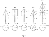
- Electrodes 4 and 5 presented in Fig. 3 and intended for the use with sensor 1 from Fig. 1 , ensure that there is no electrical contact between electrodes 4 and 5 under various weather conditions, e.g. rain, frost, snow, etc.
- Electrodes 4 and 5 are located on the non-conducting holder 13, which is fixed to the electrodes 4 and 5 at the most convex part as shown in Fig. 3 . Electrodes 4 and 5 can have several convex structures 14 made of non-conducting material on their bottom side to ensure a better contact interruption. Electrodes 4 and 5 are connected with the measurement unit 3 by means of two connecting cables 15, integrated into the holder 13 of electrodes 4 and/or 5.
- shape e.g. hemisphere, cone, cylinder
- Electrodes 4 and 5 To ensure that there is no electrical contact between electrodes 4 and 5 in various weather conditions, they must be mounted on isolated elongated holders 13. Feasibility examples are presented in Figures 4 and 5 .
- Fault current indicators which measure the magnetic field in the vicinity of conductors 10, 11 and 12 in the electrical overhead line and which, by measuring changes in magnetic field parameters, detect short circuit currents in conductors 10, 11 and 12, represent a technically known solution.
- These fault current indicators are installed at defined locations on the electrical poles 16 of the electrical overhead line. They are equipped with local signalling and communication module for wireless transmission of messages about faults and fault location to remote data centres.
- the assembly integrated in this way represents a unified device, which consists of the battery 9, the communication module 7, the signalling module 8, two separate measurement units 3 and two logic units 6 with coils for measuring the magnetic field, which is not presented in figures.
- the integrated device with sensor 1 and the fault current indicator is positioned on electrical poles 16 of electrical overhead line. It detects interrupted conductors 10, 11 and 12, and transient and permanent short circuit and ground currents and it wirelessly notifies the remote data centre about the fault type and the fault location.
Landscapes
- Physics & Mathematics (AREA)
- General Physics & Mathematics (AREA)
- Locating Faults (AREA)
- Testing Of Short-Circuits, Discontinuities, Leakage, Or Incorrect Line Connections (AREA)
- Remote Monitoring And Control Of Power-Distribution Networks (AREA)
Description
- The subject of the invention is a sensor for contactless detection of interrupted conductors in a three-phase electrical overhead line and a related method, which operates on the basis of measuring electrical field parameters around three-phase overhead lines and enables wireless notification about a fault or interruption of one or more conductors into a remote data centre. The measuring method according to this invention enables simple fault detection and, consequently, a simple construction of a sensor, which functions using at least two electrodes and does not require high precision of individual measurements. The sensor and the method according to this invention are useful for three-phase electrical overhead line networks with different configurations of conductors, e.g. horizontal, triangular, etc.
- The technical problem resolved by this invention is a sensor construction installed on a selected electrical pole of an overhead line that will enable efficient and reliable detection of changes in the electrical field surrounding the electricity overhead lines based on a method characteristic of it and it will unambiguously detect a conductor interruption and its location, which will be immediately reported to the data centre. This will result in quick and reliable information concerning the interruption of one, two or all three electric conductors of the electrical overhead lines and the information about the location of the interruption. At the same time, the construction of the sensor will be simple and compact, enabling simple installation onto the electrical poles with the possibility of simply building it into new and already existing electrical poles of the electrical overhead line. The sensor is powered by a high capacity battery for long-term operation.
- The
document FR 2 782 169 A1 - The paper accepted for presentation at the 2011 | EEE Troudheim Power Tech "On-site voltage measurement with capacitive sensors on high voltage systems" of 1. Wu et al. discloses a system with three electrodes which are coupled to three-phase overhead lines respectively and provide a voltage which represents the time derivate of the respective phase voltages. The voltages obtained by the electrodes are then integrated to reconstruct the phase voltages. By monitoring the phase voltages one can detect over voltages. This system does not monitor interrupted conductors.
- The document
WO 96/237802 A2 - The article "Broken Conductors Protection System Using Carrier Communication" of Sanger et al. in | EEE Transactions an Power Delivery, Vol. 15, No. 2, April 2000 discloses a single capacitive sensor for detecting waveforms of voltage induced in the sensor.
- It is an object of the present invention to present a sensor and a method for precise and prompt detection of interrupted conductors and of fault locations in an observed three-phase electrical overhead line network by contactless detection of these interruptions. In addition to this, the construction of the sensor must be such that its proprietary customized method will enable fast and reliable transmission of information about faults to the relevant remote data center.
- The technical problem is resolved by a sensor for contactless detection of interrupted conductors in a three-phase electrical overhead line according to
claim 1 and by a method according toclaim 4. - The invention including feasibility examples is more precisely described below, based on figures, which show as follows:
- Fig. 1
- schematic presentation of the sensor for contactless detection of interrupted conductors in the three-phase electrical overhead line network, with two electrodes
- Fig. 2
- same as in
Fig. 1 , but with a single electrode - Fig. 3
- feasibility examples of possible constructions of electrodes
- Fig. 4
- feasibility examples of possible installations of electrodes
- Fig. 5
- feasibility examples of possible installations of conductors of overhead lines
- Fig. 6
- schematic presentation of the system with a single electrode
- Fig. 7
- same as in
Fig. 6 , but a presentation with the method of substitute capacitances - Fig. 8
- scheme of a reference situation with a single electrode
- Fig. 9
- phasor diagram - U1 failure for the sensor with a single electrode
- Fig. 10
- phasor diagram - U2 failure for the sensor with a single electrode
- Fig. 11
- phasor diagram - U3 failure for the sensor with a single electrode
- Fig. 12
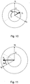
- schematic presentation of the system with two electrodes
- Fig. 13
- phasor diagram of the system with two electrodes
- Fig. 14
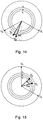
- phasor diagram - U1 failure for the sensor with two electrodes
- Fig. 15
- phasor diagram - U2 failure for the sensor with two electrodes
- Fig. 16
- phasor diagram - U3 failure for the sensor with two electrodes
- Fig. 17
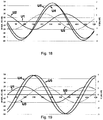
- graphical presentation of the operation of the system with two electrodes under reference conditions
- Fig. 18
- same as in
Fig. 17 , but under the following condition: U1 = 0V - Fig. 19
- same as in
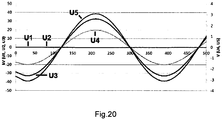
Fig. 17 , but under the following condition: U2 = 0V - Fig. 20
- same as in
Fig. 17 , but under the following condition: U1 = U2 = 0V - Individual designations in figures indicate:
- 1 - sensor with two
electrodes - 2 - sensor with
single electrode 4 - 3 - measurement unit
- 4 - electrode
- 5 - electrode
- 6 - logic unit
- 7 - communication module
- 8 - signalling module
- 9 - battery
- 10 - conductor of overhead line
- 11 - conductor of overhead line
- 12 - conductor of overhead line
- 13 - holder of
electrodes - 14 - convex structure
- 15 - connecting cable between
electrodes 4 and/or 5 and themeasurement unit 3 - 16 - electrical pole
- 17 - holder of
conductors - 18 - isolator
- The composition and operation of the claimed
sensor 1 with twoelectrodes non-claimed sensor 2 withsingle electrode 4 including the theoretical background of operation and practical application will be separately described below. - The claimed
sensor 1 with twoelectrodes Fig. 1 . It consists of themeasurement unit 3, thelogic unit 6, thecommunication module 7, thesignalling module 8 and thebattery 9. Theelectrodes measurement unit 3 with two connectingcables 15. Thelogic unit 6 is used for data processing and implements algorithms for detection of interruptedconductors 10 and/or 11 and/or 12 in overhead lines, based on the measurements of changes in the electrical field parameters under theconductors signalling module 8 is used for alarming and signalling the relevant remote data centre. Thebattery 9 supplies power to the previously mentioned component parts of thesensor 1. Thesensor 1 is preferentially mounted in the area suitable for installation ondifferent electricity pillars 16, which is presented inFig. 5 , where it measures the electrical field parameters between the ground and thelowest conductor conductors 10 and/or 11 and/or 12 of overhead lines are interrupted, thesensor 1 detects the change in electrical field parameters and based on the use of implemented algorithms, it outputs the indication of the fault or interruption. The fault and the type of fault are signalled locally with the use of theintegrated signalling module 8 with built-in light and remotely with the use of thecommunication module 7 by transmitting a message to the remote data centre, which is not displayed inFig. 1 . - The
non-claimed sensor 2, presented inFig. 2 , consists, as previously describedsensor 1, of themeasurement unit 3, thelogic unit 6 for data processing with implemented algorithms for detection of changes, thecommunication module 7 and thesignalling module 8 for alarming and signalling and ofbattery 7 for power supply. Theelectrode 4 is connected to themeasurement unit 3 with the connectingcable 15. - The
sensor 2 is, similarly as the previously describedsensor 1, mounted onto theelectricity pillars 16, i.e. to the power line poles, between the ground and thelowest conductor conductors 10 and/or 11 and/or 12 of overhead lines are interrupted, thesensor 2 operates and responds as in the previous description of thesensor 1. - The method of
sensor 1 operation for the configuration with twoelectrodes sensor 2 operation for the non-claimed configuration withsingle electrode 4 is described as follows. - The method of detection of interrupted
conductors 10 and/or 11 and/or 12 of overhead lines withsensor 1 according to the invention with twoelectrodes electrodes sensor 1 reliably detects the failure and its type, are the electrical potential amplitudes V4 and V5 in the measured locations and the phase angle Δϕ between these amplitudes. During the symmetry in the three-phase overhead line network, the phase angle Δϕ and the amplitudes V4 and V5 have certain reference values ΔφREF and VREF. In case of one interruptedconductor conductors sensor 1. The amplitudes V4 and V5 can also decrease, if thesensor 1 is located at the open end of the overhead line. - In the non-claimed case of a
single electrode 4, in the method of detection of interruptedconductors 10 and/or 11 and/or 12 of overhead lines withsensor 2, the sinusoidal electrical field potential is measured on theelectrode 4 before the fault and at the event of fault, when the electrical field changes so that the electrical field potential on theelectrode 4 keeps the frequency, but it results in the transient phase shift of the sinusoidal electrical field potential with respect to the sinusoidal electrical field potential before the fault. At the same time, the amplitude of the electrical field potential V4 of the sinusoid increases. - The methods of detection of interrupted conductors according to this invention are further described in detail, based on:
- the theoretical description, mathematical equations and diagrams,
- the simulation of the reference condition and faults,
- results of experiments carried out on a controlled test field and on real overhead line network.
- Theory of changes in electrical field near the three-phase overhead line. In the non-claimed system with
sensor 2 andsingle electrode 4. - Three
conductors conductive electrode 4 is positioned under themiddle conductor 11, at the distance h. The other two designations are distance d and height H. The configuration is presented inFig. 6 . - In view of the symmetry, this configuration can be presented with the method of substitute capacitances as presented in
Fig. 7 . - When the symmetrical three-phase voltage system U1, U2 and U3 is connected to
conductors 10 and/or 11 and/or 12, the following equations can be derived from it:


electrode 4, C1 to C7 indicate electric capacitance, Ug refers to the amplitude of the source generator voltage (Ug = |U1| = |U2| = |U3|), whereas ϕ1, ϕ2 and ϕ3 refer to the angles between phase voltages U1, U2 and U3 of the three-phase system. - The physical model presented below shows that changes, such as size of generator voltage and geometry of substitute capacitances have a large impact on the amplitude, whereas the phase angle ϕ depends only on the ratio η and is independent of the generator voltage. Various scenarios are presented on the phasor diagrams in schemes of diagrams in
Figures 8, 9 ,10 and 11 . -
Fig. 8 shows the phasor diagram where all three network voltages U1, U2 and U3 are present, which is the reference condition, resulting in the phasor of the electrical potential V 4 on the electrode 4:
- Schemes of phasor diagrams in
Figures 9 ,10 and 11 depict the conditions during single phase faults - U1 or U2 or U3. In case of failure of two phases (U1 and U3) the phasor V 4 onelectrode 4 points in the direction of the uninterrupted phase U2. This indicates that the method enables fault detection based on the detection of phase shift Δϕ of the potential V4, measured on theelectrode 4. In case of failures when twoconductors - An example of the programming procedure of the
logic unit 6 with the algorithm for fault detection based on the described method with the combination of the phase shift Δϕ and the measurement of amplitude V4 to be implemented into thelogic unit 6 includes the following steps: - Step 1:
- the initial reference measurement of potential VREF is carried out with the three-phase electrical overhead line under normal operation,
- Step 2:
- the amplitude V4 and phase angle ϕ of the potential on
electrode 4 are measured, - Step 3:
- a fault is indicated if
- a. the phase shift is |Δϕ| > |Δϕthreshold| > 0
or - b. no amplitude is present (V4≈ 0)
or - c. the measured amplitude is V4 >> VREF, e.g. V4> NV· VREF
- d. return to step 2
- a. the phase shift is |Δϕ| > |Δϕthreshold| > 0
- The described method can be used for various configurations of electrical overhead lines in the same way, however, the adjustments of the threshold value Δϕthreshold for the detection of the phase shift |Δϕ| > |Δϕthreshold| on
electrode 4 are required and the amplitude V4 > NV·V4REF must be exceeded. These threshold values can be determined statically as constants or adaptively, with dynamic adjustment, relative to the reference values or as absolute thresholds. Changing the height h of theelectrode 4 affects the ratio η, therefore Δϕthreshold and also the ratio of amplitudes V4 : V4REF change under e.g. reference conditions and faults, which influences the selection of thresholds for detection. - As the phase shift Δϕ is much more independent from external influences, e.g. weather conditions, terrain configuration, etc., the described method for the fault detection according to the invention is more reliable and effective when compared to the known methods that measure only the potential of the amplitude V4.
- The claimed system with
sensor 1 and twoelectrodes - If the previously described physical model is upgraded to two
electrodes middle conductor 11 as presented inFig. 12 , a new model can be developed by using different ratios for the potentials V4 in V5:

- In the boundary example, when the distance between
electrodes - The reference conditions in the electrical overhead line when the voltages U1, U2 and U3 are present in
conductors Fig. 13 . Examples of failure ofindividual conductors Figures 14, 15 and16 . It is evident from the graphical presentation that the phase difference Δϕ is:
electrodes conductors sensor 1. When twoconductors value 1, the more significantly larger is the phase difference ΔϕREF under the reference conditions than the phase difference Δϕ in case of faults. As the factor η depends upon the geometry or the position ofelectrodes electrodes sensor 1 and due to various geometries ofconductors - The advantage of the described method is in the fact that faults can be detected only by measuring the phase angle |Δϕ| < |ΔϕREF| and it is not required to include the measurement of amplitudes V4 and V5, except when all the
conductors - In this way, detection is performed with a simple algorithm and the fault is indicated if the phase difference Δϕ between the amplitudes V4 and V5 (according to equation seven) is smaller than the threshold value |Δϕthreshold| (|Δϕ| < (|Δϕthreshold |). The threshold value Δϕthreshold can be determined statically as a constant or adaptively, with dynamic adjustment, absolutely or relatively, in view of the reference value Δϕthreshold = Nφ·ΔϕREF with Nφ < 1.
- The physical model is easily applied also for other forms of symmetrical and asymmetrical configurations, e.g. for a symmetrical or asymmetrical triangle. but with different ratios K (equation two) and η (equation three), which means that
electrodes - To better illustrate the previously presented physical model and results of equations, this model can be presented also in graphical form.
- Furthermore, a feasibility example is presented with a system with two
electrodes conductors electrodes Figures 17 ,18 ,19 and20 . The summary of results is presented in table 1.Table 1 - summary of simulation under various conditions Conditions |V4| in |V5| |Δϕ| U1 = U2 = U3 = 11.56 kV 1 92° U1 =0V, U2 =U3 = 11.56 kV 4.5 8° U2 =0V, U1 =U3 = 11.56 kV 5.1 18° U1 = U2 = 0V, U2 = 11.56 kV 4.4 0° - The simulation shows that the phase difference Δϕ and the amplitudes V4 and V5 change significantly - as previously predicted by the theoretical physical model.
- Below the tests with
sensors - Test results on the controlled medium-voltage test field.
- The practical example was carried out on the controlled medium-voltage test field, with
voltages conductors conductors - The tests were carried out with the
sensor 1 with twoelectrodes conductors Table 2 - example of results, two electrodes Voltage conditions (presence of individual phases) Geometry Parameter U1 U2 U3 U1 U2 U1 U3 U2 U3 Horizontal |Δϕ| 169° 12° 49° 15° V4 34 60 84 81 V 517 59 56 49 Delta |Δϕ| 83° 27° 55° 2° V4 68 133 185 175 V5 39 72 75 61 Triangular |Δϕ| 112° 13° 60° 17° V4 70 89 146 136 V5 36 76 75 52 - Results at 11.56 kV in table 2 indicate that although the electric potentials V4 and V5 on
electrodes electrodes electrodes conductors electrodes sensor 1 are required, in view of the to the network geometry, the terrain configuration, etc. On the other hand, the measurements of the phase angle difference Δϕ between the potentials V4 and V5 onelectrodes conductors - As the ratio K (equation two) depends on more factors than the ratio η (equation three), it is less difficult to adjust the parameter η.
- Tests in real environment were carried out on 20 kV MV electrical overhead line. Various constructions of
sensors - The test of conductor interruption on 20 MV overhead electric line was carried out to test the detection of various types of faults and to test both
sensors sensor 1 with the open unloaded electrical overhead line and with the same, but the loaded electrical overhead line are presented in Table 3.Table 3 - test results in real environment Voltage conditions (presence of individual phases) Open line (unloaded) Loaded line Parameter U1 U2 U3 U2 U3 U3 U1 U2 U3 U2 U3 |Δϕ| 90° 10° 0,2° 90° 12° V4 320 900 970 320 900 V5 330 900 970 320 900 - The test results obtained in real environment confirm the theory and findings acquired in the controlled test field. Based on this, various algorithms for detecting interrupted
conductors 10 and/or 11 and/or 12 in the electrical overhead line can be implemented. - An example of an algorithm for detecting interrupted conductors is presented in the table 4 below.
Table 4 - examples of implemented algorithms, absolute angle considered Constructions of electrodes. Algorithm that considers an absolute angle for sensor with the distance between electrodes of 0.2 m or more Condition on the overhead electric line All conductors uninterrupted One conductor interrupted Two conductors interrupted All conductors interrupted Phase difference between electrodes 100% 80% ≥ |Δϕ| ≥ 5% |Δϕ| < 5 % No signal Value of potential 100% >150% >150% < 50% CONDITION OK FAULT Fault or disconnected conductor - The constructions of
electrodes Fig. 3 and intended for the use withsensor 1 fromFig. 1 , ensure that there is no electrical contact betweenelectrodes - This is ensured with the application of the shape (e.g. hemisphere, cone, cylinder) of
electrodes electrodes non-conducting holder 13, which is fixed to theelectrodes Fig. 3 .Electrodes convex structures 14 made of non-conducting material on their bottom side to ensure a better contact interruption.Electrodes measurement unit 3 by means of two connectingcables 15, integrated into theholder 13 ofelectrodes 4 and/or 5. - To ensure that there is no electrical contact between
electrodes elongated holders 13. Feasibility examples are presented inFigures 4 and5 . - The implementation of a system with
integrated sensor 1 for detecting interruptedconductors - Fault current indicators, which measure the magnetic field in the vicinity of
conductors conductors electrical poles 16 of the electrical overhead line. They are equipped with local signalling and communication module for wireless transmission of messages about faults and fault location to remote data centres. - Due to the structural similarity of fault current indicators for detecting interrupted
conductors sensor 1, the subject of this invention, is carried out. The assembly integrated in this way represents a unified device, which consists of thebattery 9, thecommunication module 7, thesignalling module 8, twoseparate measurement units 3 and twologic units 6 with coils for measuring the magnetic field, which is not presented in figures. - The integrated device with
sensor 1 and the fault current indicator is positioned onelectrical poles 16 of electrical overhead line. It detects interruptedconductors
Claims (7)
- Sensor for contactless detection of interrupted conductors (10, 11, 12) in a three-phase electrical overhead line, comprising a measurement unit (3), a logic unit (6), a communication module (7), a signalling module (8) and a battery (9), characterised by the fact that at least one first electrode (4) and at least one further electrode (5) are connected to the measurement unit (3) through corresponding connecting cables (15) and that the electrodes (4, 5) are placed at two points in the vicinity of the electrical overhead line; that the observed parameters, on the basis of which the sensor is configured to determine the interruption and the type of interruption, include phase angle (Δϕ) between sinusoids of the electrical potential on the electrodes (4, 5) as well as electrical potential amplitudes (V4, V5) at observed points; wherein, in symmetry, phase angle (Δϕ) and amplitudes (V4, V5) have certain reference values (ΔϕREF, VREF); and, in case of one interrupted conductor (10, 11, 12) the phase angle (Δϕ) is reduced, whereas amplitudes (V4, V5) increase; and in case of two interrupted conductors (10 and 11, 10 and 12, 11 and 12), the phase angle (Δϕ) between sinusoids of electrical potential on both electrodes (4, 5) is approximately zero, whereas amplitudes (V4, V5) further increase if a three-phase transformer is connected to the electrical overhead line after the sensor (1) or are even slightly reduced if sensor (1) is positioned at the end of an open electrical overhead line.
- Sensor according to claim 1 characterised by the fact that the first and further electrodes (4, 5) are in the shape of a hemisphere, cone or cylinder.
- Sensor according to claim 1, characterised by the fact that the combination of the change in the phase angle (Δϕ) and the change in the electrical potential amplitudes (V4, V5), regarding the condition before the fault, at the occurrence of the fault or after the fault, is used for an algorithm of the sensor (1) for detecting broken conductors (10, 11, 12).
- Method for contactless detection of interrupted conductors (10, 11, 12) in a three-phase electrical overhead line, using the sensor of claim 1, characterised by the fact that the sinusoid of the electrical field potential on the first electrode (4) is measured before the fault and at the occurrence of the fault or after the fault when the electrical field changes so that a transient time shift of the sinusoid of the electrical potential occurs in relation to the sinusoid of the electric potential before the fault, also the amplitude (V4) of the sinusoid increases at the same time.
- Sensor according to claim 1 or claim 2, characterised by the fact that the sensor (1) is positioned on an electrical pole (16) in the area between the ground and the lowest conductor (10, 11, 12), where the optimal measurement of electrical field parameters round the electrical overhead line is made possible.
- Sensor according to claim 1 or claim 2, characterised by the fact that, by integration of a fault current indicator with the sensor (1), an assembled unit is obtained, which includes the battery (9), the communication module (7), the signalling module (8) and two separate measurement units (3) and two separate logic units (6), including coils for measuring the magnetic field.
- Sensor according to claim 6, characterised by the fact that the integrated device is mounted on an electrical pole (16) of the electrical overhead line and that it is configured to detect interrupted conductors (10, 11, 12) and a transient and permanent short circuit and ground currents in conductors (10, 11, 12) and to wirelessly notify a remote data centre about the type and location of fault.
Priority Applications (2)
| Application Number | Priority Date | Filing Date | Title |
|---|---|---|---|
| HRP20211576TT HRP20211576T1 (en) | 2014-09-24 | 2015-09-24 | Sensor for contactless detection of interrupted conductors in three-phase electrical overhead line and related method |
| RS20211428A RS62617B1 (en) | 2014-09-24 | 2015-09-24 | Sensor for contactless detection of interrupted conductors in three-phase eletrical overhead line and related method |
Applications Claiming Priority (1)
| Application Number | Priority Date | Filing Date | Title |
|---|---|---|---|
| SI201400330A SI24793B (en) | 2014-09-24 | 2014-09-24 | Wireless sensor detecting disconection of conductors in three-phase overground electricity line and a method relating to this |
Publications (2)
| Publication Number | Publication Date |
|---|---|
| EP3001203A1 EP3001203A1 (en) | 2016-03-30 |
| EP3001203B1 true EP3001203B1 (en) | 2021-09-22 |
Family
ID=54199581
Family Applications (1)
| Application Number | Title | Priority Date | Filing Date |
|---|---|---|---|
| EP15186628.2A Active EP3001203B1 (en) | 2014-09-24 | 2015-09-24 | Sensor for contactless detection of interrupted conductors in three-phase eletrical overhead line and related method |
Country Status (5)
| Country | Link |
|---|---|
| EP (1) | EP3001203B1 (en) |
| CA (1) | CA2905482C (en) |
| HR (1) | HRP20211576T1 (en) |
| RS (1) | RS62617B1 (en) |
| SI (1) | SI24793B (en) |
Families Citing this family (1)
| Publication number | Priority date | Publication date | Assignee | Title |
|---|---|---|---|---|
| CN111965565A (en) * | 2020-08-25 | 2020-11-20 | 广东电网有限责任公司广州供电局 | Cable line fault reason judgment method, device, equipment and medium |
Family Cites Families (8)
| Publication number | Priority date | Publication date | Assignee | Title |
|---|---|---|---|---|
| DE3812055A1 (en) * | 1988-04-12 | 1989-10-26 | Reinhausen Maschf Scheubeck | METHOD FOR CORRECTING THE MEASURING VOLTAGE OUTPUT BY A COUPLING SUPPORT ISOLATOR ARRANGED IN A TURNOVER SYSTEM |
| FI100828B (en) * | 1995-03-08 | 1998-02-27 | Powex Oy | Measuring device for measuring the current in overhead lines of a medium voltage line |
| FR2782169A1 (en) * | 1998-08-05 | 2000-02-11 | Alstom Technology | A system for measuring the voltage in an overhead power cable from a position on the earth is by measurement of the cable's electric field using electrodes placed at ground level |
| JP3765780B2 (en) * | 2001-09-06 | 2006-04-12 | 株式会社北計工業 | Electromagnetic field sensor |
| SI21482A (en) | 2004-06-01 | 2004-10-31 | Marjan Bezjak | Device for detecting and shutdown of an interrupted semi-insulated conductor in medium voltage power lines |
| SI21717A (en) | 2005-05-23 | 2005-08-31 | Marjan Bezjak | DETECTION CIRCUIT OF THE PROTECTIVE CIRCUIT FOR DETECTION AND DISCONTINUATION OF INTERRUPTED ELECTRICAL CONDUCTORS IN THE ELECTRICITY ELECTRICITY NETWORK |
| SI22276A (en) * | 2007-07-27 | 2007-10-31 | Mag. Bezjak Marjan, Univ.Dipl.Ing.El | Device and method for indication and notification of changes in a three-phase voltage system of a power line with the aim of detecting interrupted conductors |
| SI22461A (en) | 2008-04-09 | 2008-08-31 | Mmb Mag. Marjan Bezjak S.P. | Device and method for remote operation control of the mv/lv transformer station with corresponding mv electric power lines for remote error reporting inside of them |
-
2014
- 2014-09-24 SI SI201400330A patent/SI24793B/en active Search and Examination
-
2015
- 2015-09-24 HR HRP20211576TT patent/HRP20211576T1/en unknown
- 2015-09-24 RS RS20211428A patent/RS62617B1/en unknown
- 2015-09-24 EP EP15186628.2A patent/EP3001203B1/en active Active
- 2015-09-24 CA CA2905482A patent/CA2905482C/en active Active
Also Published As
| Publication number | Publication date |
|---|---|
| RS62617B1 (en) | 2021-12-31 |
| EP3001203A1 (en) | 2016-03-30 |
| SI24793B (en) | 2024-04-30 |
| CA2905482A1 (en) | 2016-03-24 |
| SI24793A (en) | 2016-02-29 |
| CA2905482C (en) | 2022-08-30 |
| HRP20211576T1 (en) | 2021-12-24 |
Similar Documents
| Publication | Publication Date | Title |
|---|---|---|
| AU2019246817B2 (en) | Electrical monitoring and evaluation process | |
| US9823637B2 (en) | Fault detection and isolation using a common reference clock | |
| ES2665815T3 (en) | Procedure and device to detect the direction of ground contact in a three-phase electric current network | |
| US20190317143A1 (en) | Detection and location of broken conductors for transmission lines | |
| EP2895873B1 (en) | Gsm/gprs system to detect and locate high impedance faults on medium voltage distribution networks in high resistivity areas | |
| US11733276B2 (en) | Power line sag monitoring device | |
| US11513166B2 (en) | Ground fault detection in ungrounded power systems | |
| CN104894571B (en) | Cathodic protection supply unit and its method of work with drainage function | |
| CN103033686B (en) | For having the method that the insulation fault of dynamic response characteristic is monitored | |
| JP2012007903A (en) | Degradation diagnosis tool for external gap type arrester | |
| KR101604344B1 (en) | Protection potential measurement system of underground pipeline of high-speed mobile Based on low-power | |
| CN103050907B (en) | Security maintenance method for common grounding electrode of direct current power transmission systems | |
| RU2682240C2 (en) | Detecting fault, in particular transient fault in electrical network | |
| JP2018141215A (en) | Measurement and evaluation method for DC stray current corrosion risk | |
| EP3001203A1 (en) | Sensor for contactless detection of interrupted conductors in three-phase eletrical overhead line and related method | |
| US9804078B2 (en) | Multiple coupon apparatus for cathodic protection testing | |
| CN104297624A (en) | Direct current ground fault detecting and handling method | |
| US20220099755A1 (en) | Leakage Voltage Detection System and Leakage Voltage Detection Method | |
| KR101659480B1 (en) | Bluetooth Low Energy Based Theft Detecting and Tracking System for Electric Power Distribution Lines | |
| US11972913B2 (en) | Disconnector device with passive radio device, grid protection system having the disconnector device, and method for indicating a state of the disconnector device | |
| RU121083U1 (en) | LEAKAGE CURRENT CONTROL DEVICE IN THE GROUNDING CIRCUIT OF THE SUPPORT STRUCTURE OF THE ELECTRIC TRANSMISSION LINES | |
| JPH02210724A (en) | Detection of defective insulator | |
| JP2016033633A (en) | Optical drop cable collating device utilizing auxiliary signal |
Legal Events
| Date | Code | Title | Description |
|---|---|---|---|
| PUAI | Public reference made under article 153(3) epc to a published international application that has entered the european phase |
Free format text: ORIGINAL CODE: 0009012 |
|
| AK | Designated contracting states |
Kind code of ref document: A1 Designated state(s): AL AT BE BG CH CY CZ DE DK EE ES FI FR GB GR HR HU IE IS IT LI LT LU LV MC MK MT NL NO PL PT RO RS SE SI SK SM TR |
|
| AX | Request for extension of the european patent |
Extension state: BA ME |
|
| 17P | Request for examination filed |
Effective date: 20160930 |
|
| RBV | Designated contracting states (corrected) |
Designated state(s): AL AT BE BG CH CY CZ DE DK EE ES FI FR GB GR HR HU IE IS IT LI LT LU LV MC MK MT NL NO PL PT RO RS SE SI SK SM TR |
|
| GRAP | Despatch of communication of intention to grant a patent |
Free format text: ORIGINAL CODE: EPIDOSNIGR1 |
|
| STAA | Information on the status of an ep patent application or granted ep patent |
Free format text: STATUS: GRANT OF PATENT IS INTENDED |
|
| INTG | Intention to grant announced |
Effective date: 20210518 |
|
| GRAS | Grant fee paid |
Free format text: ORIGINAL CODE: EPIDOSNIGR3 |
|
| GRAA | (expected) grant |
Free format text: ORIGINAL CODE: 0009210 |
|
| STAA | Information on the status of an ep patent application or granted ep patent |
Free format text: STATUS: THE PATENT HAS BEEN GRANTED |
|
| AK | Designated contracting states |
Kind code of ref document: B1 Designated state(s): AL AT BE BG CH CY CZ DE DK EE ES FI FR GB GR HR HU IE IS IT LI LT LU LV MC MK MT NL NO PL PT RO RS SE SI SK SM TR |
|
| REG | Reference to a national code |
Ref country code: GB Ref legal event code: FG4D |
|
| REG | Reference to a national code |
Ref country code: DE Ref legal event code: R096 Ref document number: 602015073472 Country of ref document: DE |
|
| REG | Reference to a national code |
Ref country code: IE Ref legal event code: FG4D |
|
| REG | Reference to a national code |
Ref country code: CH Ref legal event code: EP Ref country code: AT Ref legal event code: REF Ref document number: 1432732 Country of ref document: AT Kind code of ref document: T Effective date: 20211015 |
|
| REG | Reference to a national code |
Ref country code: HR Ref legal event code: T1PR Ref document number: P20211576 Country of ref document: HR Ref country code: HR Ref legal event code: ODRP Ref document number: P20211576 Country of ref document: HR Payment date: 20211007 Year of fee payment: 7 |
|
| REG | Reference to a national code |
Ref country code: LT Ref legal event code: MG9D |
|
| REG | Reference to a national code |
Ref country code: NL Ref legal event code: MP Effective date: 20210922 |
|
| PG25 | Lapsed in a contracting state [announced via postgrant information from national office to epo] |
Ref country code: SE Free format text: LAPSE BECAUSE OF FAILURE TO SUBMIT A TRANSLATION OF THE DESCRIPTION OR TO PAY THE FEE WITHIN THE PRESCRIBED TIME-LIMIT Effective date: 20210922 Ref country code: NO Free format text: LAPSE BECAUSE OF FAILURE TO SUBMIT A TRANSLATION OF THE DESCRIPTION OR TO PAY THE FEE WITHIN THE PRESCRIBED TIME-LIMIT Effective date: 20211222 Ref country code: FI Free format text: LAPSE BECAUSE OF FAILURE TO SUBMIT A TRANSLATION OF THE DESCRIPTION OR TO PAY THE FEE WITHIN THE PRESCRIBED TIME-LIMIT Effective date: 20210922 Ref country code: LT Free format text: LAPSE BECAUSE OF FAILURE TO SUBMIT A TRANSLATION OF THE DESCRIPTION OR TO PAY THE FEE WITHIN THE PRESCRIBED TIME-LIMIT Effective date: 20210922 Ref country code: BG Free format text: LAPSE BECAUSE OF FAILURE TO SUBMIT A TRANSLATION OF THE DESCRIPTION OR TO PAY THE FEE WITHIN THE PRESCRIBED TIME-LIMIT Effective date: 20211222 |
|
| REG | Reference to a national code |
Ref country code: AT Ref legal event code: MK05 Ref document number: 1432732 Country of ref document: AT Kind code of ref document: T Effective date: 20210922 |
|
| PG25 | Lapsed in a contracting state [announced via postgrant information from national office to epo] |
Ref country code: LV Free format text: LAPSE BECAUSE OF FAILURE TO SUBMIT A TRANSLATION OF THE DESCRIPTION OR TO PAY THE FEE WITHIN THE PRESCRIBED TIME-LIMIT Effective date: 20210922 Ref country code: GR Free format text: LAPSE BECAUSE OF FAILURE TO SUBMIT A TRANSLATION OF THE DESCRIPTION OR TO PAY THE FEE WITHIN THE PRESCRIBED TIME-LIMIT Effective date: 20211223 |
|
| PG25 | Lapsed in a contracting state [announced via postgrant information from national office to epo] |
Ref country code: AT Free format text: LAPSE BECAUSE OF FAILURE TO SUBMIT A TRANSLATION OF THE DESCRIPTION OR TO PAY THE FEE WITHIN THE PRESCRIBED TIME-LIMIT Effective date: 20210922 |
|
| REG | Reference to a national code |
Ref country code: CH Ref legal event code: PL |
|
| REG | Reference to a national code |
Ref country code: BE Ref legal event code: MM Effective date: 20210930 |
|
| PG25 | Lapsed in a contracting state [announced via postgrant information from national office to epo] |
Ref country code: IS Free format text: LAPSE BECAUSE OF FAILURE TO SUBMIT A TRANSLATION OF THE DESCRIPTION OR TO PAY THE FEE WITHIN THE PRESCRIBED TIME-LIMIT Effective date: 20220122 Ref country code: SK Free format text: LAPSE BECAUSE OF FAILURE TO SUBMIT A TRANSLATION OF THE DESCRIPTION OR TO PAY THE FEE WITHIN THE PRESCRIBED TIME-LIMIT Effective date: 20210922 Ref country code: RO Free format text: LAPSE BECAUSE OF FAILURE TO SUBMIT A TRANSLATION OF THE DESCRIPTION OR TO PAY THE FEE WITHIN THE PRESCRIBED TIME-LIMIT Effective date: 20210922 Ref country code: PT Free format text: LAPSE BECAUSE OF FAILURE TO SUBMIT A TRANSLATION OF THE DESCRIPTION OR TO PAY THE FEE WITHIN THE PRESCRIBED TIME-LIMIT Effective date: 20220124 Ref country code: PL Free format text: LAPSE BECAUSE OF FAILURE TO SUBMIT A TRANSLATION OF THE DESCRIPTION OR TO PAY THE FEE WITHIN THE PRESCRIBED TIME-LIMIT Effective date: 20210922 Ref country code: NL Free format text: LAPSE BECAUSE OF FAILURE TO SUBMIT A TRANSLATION OF THE DESCRIPTION OR TO PAY THE FEE WITHIN THE PRESCRIBED TIME-LIMIT Effective date: 20210922 Ref country code: ES Free format text: LAPSE BECAUSE OF FAILURE TO SUBMIT A TRANSLATION OF THE DESCRIPTION OR TO PAY THE FEE WITHIN THE PRESCRIBED TIME-LIMIT Effective date: 20210922 Ref country code: EE Free format text: LAPSE BECAUSE OF FAILURE TO SUBMIT A TRANSLATION OF THE DESCRIPTION OR TO PAY THE FEE WITHIN THE PRESCRIBED TIME-LIMIT Effective date: 20210922 Ref country code: CZ Free format text: LAPSE BECAUSE OF FAILURE TO SUBMIT A TRANSLATION OF THE DESCRIPTION OR TO PAY THE FEE WITHIN THE PRESCRIBED TIME-LIMIT Effective date: 20210922 Ref country code: AL Free format text: LAPSE BECAUSE OF FAILURE TO SUBMIT A TRANSLATION OF THE DESCRIPTION OR TO PAY THE FEE WITHIN THE PRESCRIBED TIME-LIMIT Effective date: 20210922 |
|
| REG | Reference to a national code |
Ref country code: DE Ref legal event code: R097 Ref document number: 602015073472 Country of ref document: DE |
|
| PG25 | Lapsed in a contracting state [announced via postgrant information from national office to epo] |
Ref country code: MC Free format text: LAPSE BECAUSE OF FAILURE TO SUBMIT A TRANSLATION OF THE DESCRIPTION OR TO PAY THE FEE WITHIN THE PRESCRIBED TIME-LIMIT Effective date: 20210922 |
|
| PG25 | Lapsed in a contracting state [announced via postgrant information from national office to epo] |
Ref country code: LU Free format text: LAPSE BECAUSE OF NON-PAYMENT OF DUE FEES Effective date: 20210924 Ref country code: IE Free format text: LAPSE BECAUSE OF NON-PAYMENT OF DUE FEES Effective date: 20210924 Ref country code: DK Free format text: LAPSE BECAUSE OF FAILURE TO SUBMIT A TRANSLATION OF THE DESCRIPTION OR TO PAY THE FEE WITHIN THE PRESCRIBED TIME-LIMIT Effective date: 20210922 Ref country code: BE Free format text: LAPSE BECAUSE OF NON-PAYMENT OF DUE FEES Effective date: 20210930 |
|
| PLBE | No opposition filed within time limit |
Free format text: ORIGINAL CODE: 0009261 |
|
| STAA | Information on the status of an ep patent application or granted ep patent |
Free format text: STATUS: NO OPPOSITION FILED WITHIN TIME LIMIT |
|
| GBPC | Gb: european patent ceased through non-payment of renewal fee |
Effective date: 20211222 |
|
| 26N | No opposition filed |
Effective date: 20220623 |
|
| PG25 | Lapsed in a contracting state [announced via postgrant information from national office to epo] |
Ref country code: LI Free format text: LAPSE BECAUSE OF NON-PAYMENT OF DUE FEES Effective date: 20210930 Ref country code: CH Free format text: LAPSE BECAUSE OF NON-PAYMENT OF DUE FEES Effective date: 20210930 |
|
| REG | Reference to a national code |
Ref country code: HR Ref legal event code: ODRP Ref document number: P20211576 Country of ref document: HR Payment date: 20220914 Year of fee payment: 8 |
|
| PG25 | Lapsed in a contracting state [announced via postgrant information from national office to epo] |
Ref country code: GB Free format text: LAPSE BECAUSE OF NON-PAYMENT OF DUE FEES Effective date: 20211222 |
|
| PG25 | Lapsed in a contracting state [announced via postgrant information from national office to epo] |
Ref country code: SI Free format text: LAPSE BECAUSE OF FAILURE TO SUBMIT A TRANSLATION OF THE DESCRIPTION OR TO PAY THE FEE WITHIN THE PRESCRIBED TIME-LIMIT Effective date: 20210922 |
|
| PG25 | Lapsed in a contracting state [announced via postgrant information from national office to epo] |
Ref country code: IT Free format text: LAPSE BECAUSE OF FAILURE TO SUBMIT A TRANSLATION OF THE DESCRIPTION OR TO PAY THE FEE WITHIN THE PRESCRIBED TIME-LIMIT Effective date: 20210922 |
|
| PG25 | Lapsed in a contracting state [announced via postgrant information from national office to epo] |
Ref country code: HU Free format text: LAPSE BECAUSE OF FAILURE TO SUBMIT A TRANSLATION OF THE DESCRIPTION OR TO PAY THE FEE WITHIN THE PRESCRIBED TIME-LIMIT; INVALID AB INITIO Effective date: 20150924 |
|
| PG25 | Lapsed in a contracting state [announced via postgrant information from national office to epo] |
Ref country code: CY Free format text: LAPSE BECAUSE OF FAILURE TO SUBMIT A TRANSLATION OF THE DESCRIPTION OR TO PAY THE FEE WITHIN THE PRESCRIBED TIME-LIMIT Effective date: 20210922 |
|
| PG25 | Lapsed in a contracting state [announced via postgrant information from national office to epo] |
Ref country code: SM Free format text: LAPSE BECAUSE OF FAILURE TO SUBMIT A TRANSLATION OF THE DESCRIPTION OR TO PAY THE FEE WITHIN THE PRESCRIBED TIME-LIMIT Effective date: 20210922 |
|
| REG | Reference to a national code |
Ref country code: HR Ref legal event code: ODRP Ref document number: P20211576 Country of ref document: HR Payment date: 20230913 Year of fee payment: 9 |
|
| PG25 | Lapsed in a contracting state [announced via postgrant information from national office to epo] |
Ref country code: MK Free format text: LAPSE BECAUSE OF FAILURE TO SUBMIT A TRANSLATION OF THE DESCRIPTION OR TO PAY THE FEE WITHIN THE PRESCRIBED TIME-LIMIT Effective date: 20210922 |
|
| PG25 | Lapsed in a contracting state [announced via postgrant information from national office to epo] |
Ref country code: TR Free format text: LAPSE BECAUSE OF FAILURE TO SUBMIT A TRANSLATION OF THE DESCRIPTION OR TO PAY THE FEE WITHIN THE PRESCRIBED TIME-LIMIT Effective date: 20210922 |
|
| PG25 | Lapsed in a contracting state [announced via postgrant information from national office to epo] |
Ref country code: MT Free format text: LAPSE BECAUSE OF FAILURE TO SUBMIT A TRANSLATION OF THE DESCRIPTION OR TO PAY THE FEE WITHIN THE PRESCRIBED TIME-LIMIT Effective date: 20210922 |
|
| REG | Reference to a national code |
Ref country code: HR Ref legal event code: ODRP Ref document number: P20211576 Country of ref document: HR Payment date: 20240920 Year of fee payment: 10 |
|
| PGFP | Annual fee paid to national office [announced via postgrant information from national office to epo] |
Ref country code: DE Payment date: 20250905 Year of fee payment: 11 |
|
| REG | Reference to a national code |
Ref country code: HR Ref legal event code: ODRP Ref document number: P20211576 Country of ref document: HR Payment date: 20250916 Year of fee payment: 11 |
|
| PGFP | Annual fee paid to national office [announced via postgrant information from national office to epo] |
Ref country code: HR Payment date: 20250916 Year of fee payment: 11 |
|
| PGFP | Annual fee paid to national office [announced via postgrant information from national office to epo] |
Ref country code: FR Payment date: 20250924 Year of fee payment: 11 |
|
| PGFP | Annual fee paid to national office [announced via postgrant information from national office to epo] |
Ref country code: RS Payment date: 20250916 Year of fee payment: 11 |