EP3001107A1 - Mixer retention - Google Patents
Mixer retention Download PDFInfo
- Publication number
- EP3001107A1 EP3001107A1 EP15187480.7A EP15187480A EP3001107A1 EP 3001107 A1 EP3001107 A1 EP 3001107A1 EP 15187480 A EP15187480 A EP 15187480A EP 3001107 A1 EP3001107 A1 EP 3001107A1
- Authority
- EP
- European Patent Office
- Prior art keywords
- mixer
- liner
- panel
- engine
- aircraft
- Prior art date
- Legal status (The legal status is an assumption and is not a legal conclusion. Google has not performed a legal analysis and makes no representation as to the accuracy of the status listed.)
- Granted
Links
Images



Classifications
-
- F—MECHANICAL ENGINEERING; LIGHTING; HEATING; WEAPONS; BLASTING
- F23—COMBUSTION APPARATUS; COMBUSTION PROCESSES
- F23R—GENERATING COMBUSTION PRODUCTS OF HIGH PRESSURE OR HIGH VELOCITY, e.g. GAS-TURBINE COMBUSTION CHAMBERS
- F23R3/00—Continuous combustion chambers using liquid or gaseous fuel
- F23R3/28—Continuous combustion chambers using liquid or gaseous fuel characterised by the fuel supply
- F23R3/286—Continuous combustion chambers using liquid or gaseous fuel characterised by the fuel supply having fuel-air premixing devices
-
- F—MECHANICAL ENGINEERING; LIGHTING; HEATING; WEAPONS; BLASTING
- F23—COMBUSTION APPARATUS; COMBUSTION PROCESSES
- F23R—GENERATING COMBUSTION PRODUCTS OF HIGH PRESSURE OR HIGH VELOCITY, e.g. GAS-TURBINE COMBUSTION CHAMBERS
- F23R3/00—Continuous combustion chambers using liquid or gaseous fuel
- F23R3/02—Continuous combustion chambers using liquid or gaseous fuel characterised by the air-flow or gas-flow configuration
- F23R3/04—Air inlet arrangements
- F23R3/10—Air inlet arrangements for primary air
- F23R3/12—Air inlet arrangements for primary air inducing a vortex
- F23R3/14—Air inlet arrangements for primary air inducing a vortex by using swirl vanes
-
- F—MECHANICAL ENGINEERING; LIGHTING; HEATING; WEAPONS; BLASTING
- F23—COMBUSTION APPARATUS; COMBUSTION PROCESSES
- F23R—GENERATING COMBUSTION PRODUCTS OF HIGH PRESSURE OR HIGH VELOCITY, e.g. GAS-TURBINE COMBUSTION CHAMBERS
- F23R3/00—Continuous combustion chambers using liquid or gaseous fuel
- F23R3/28—Continuous combustion chambers using liquid or gaseous fuel characterised by the fuel supply
- F23R3/283—Attaching or cooling of fuel injecting means including supports for fuel injectors, stems, or lances
-
- F—MECHANICAL ENGINEERING; LIGHTING; HEATING; WEAPONS; BLASTING
- F23—COMBUSTION APPARATUS; COMBUSTION PROCESSES
- F23R—GENERATING COMBUSTION PRODUCTS OF HIGH PRESSURE OR HIGH VELOCITY, e.g. GAS-TURBINE COMBUSTION CHAMBERS
- F23R2900/00—Special features of, or arrangements for continuous combustion chambers; Combustion processes therefor
- F23R2900/00017—Assembling combustion chamber liners or subparts
-
- F—MECHANICAL ENGINEERING; LIGHTING; HEATING; WEAPONS; BLASTING
- F23—COMBUSTION APPARATUS; COMBUSTION PROCESSES
- F23R—GENERATING COMBUSTION PRODUCTS OF HIGH PRESSURE OR HIGH VELOCITY, e.g. GAS-TURBINE COMBUSTION CHAMBERS
- F23R2900/00—Special features of, or arrangements for continuous combustion chambers; Combustion processes therefor
- F23R2900/00018—Manufacturing combustion chamber liners or subparts
-
- F—MECHANICAL ENGINEERING; LIGHTING; HEATING; WEAPONS; BLASTING
- F23—COMBUSTION APPARATUS; COMBUSTION PROCESSES
- F23R—GENERATING COMBUSTION PRODUCTS OF HIGH PRESSURE OR HIGH VELOCITY, e.g. GAS-TURBINE COMBUSTION CHAMBERS
- F23R2900/00—Special features of, or arrangements for continuous combustion chambers; Combustion processes therefor
- F23R2900/00019—Repairing or maintaining combustion chamber liners or subparts
Definitions
- Mixers are used to mix reactants with one another.
- mixers may assist in a mixing of air and fuel to facilitate combustion in an aerospace environment.
- mixers are mounted to a bulkhead via brazing.
- a mechanical attachment technique can be used. Such mechanical attachment techniques include the use of straps to clamp down the mixer and a bolting to the bulkhead's heat shield studs. "Ears" can be added to the mixer such that the ears are retained by the heat shield studs.
- Design requirements or constraints can influence the type of mounting that is used. For example, packaging constraints and a count of mixers used on a given platform may render conventional mounting techniques impractical.
- aspects of the disclosure are directed to a method comprising: coupling a surface of a liner of a gas turbine engine of an aircraft to a fuel/air mixer, and coupling a surface of a panel of the engine to the mixer such that a portion of the mixer is disposed between the liner surface and the panel surface.
- the method comprises coupling the panel to the liner.
- the method comprises bolting the panel to at least one of the liner, the mixer, and a body of the aircraft.
- the method comprises decoupling the panel from the mixer.
- the method comprises servicing at least one of the liner and the mixer.
- the servicing of the at least one of the liner and the mixer comprises repairing the at least one of the liner and the mixer. In some embodiments, the servicing of the at least one of the liner and the mixer comprises replacing the at least one of the liner and the mixer. In some embodiments, the method comprises recoupling the panel subsequent to the servicing. In some embodiments, the portion of the mixer that is disposed between the liner and the panel corresponds to a flange of the mixer.
- aspects of the disclosure are directed to a system comprising: a liner of a gas turbine engine of an aircraft, a panel of the engine, and a fuel/air mixer associated with a combustion chamber of the aircraft, wherein a portion of the mixer is disposed between a surface of the liner and a surface of the panel.
- the liner comprises sheet metal.
- the panel is at least one of cast and molded.
- the portion of the mixer that is disposed between the liner and the panel comprises a flange of the mixer.
- the mixer is configured to have a conical shape to match a conical shape of the panel.
- the liner is configured to have a flat surface, and wherein the panel and the mixer are configured to have flat, circular shapes.
- the mixer is a swirler.
- connections are set forth between elements in the following description and in the drawings (the contents of which are included in this disclosure by way of reference). It is noted that these connections are general and, unless specified otherwise, may be direct or indirect and that this specification is not intended to be limiting in this respect.
- a coupling between two or more entities may refer to a direct connection or an indirect connection.
- An indirect connection may incorporate one or more intervening entities.
- apparatuses, systems and methods are described for retaining a mixer.
- a panel of, e.g., a bulkhead may be used as part of the mixer retention/sealing, allowing for a reduced packaging envelope. Accordingly, greater flexibility may be obtained in terms of mixer sizing and location. Mixers may be easily replaced in accordance with aspects of the disclosure, thereby reducing costs associated with maintenance.
- the system 100 includes mixers 102. Due to spacing, or lack thereof, forming a sealing surface for the mixers 102 in a sheet metal liner 104 is not possible.
- One or more retaining rings 106 are shown as being associated with the mixers 102.
- a retaining ring 106 requires brazing or welding, which represents a manufacturing cost.
- the brazing or welding also makes the mixer 102 inseparable from the liner 104, which makes maintenance and replacement costly. For example, degradation or breakage experienced in the liner 104 and/or one or more of the mixers 102 results in the entirety of the liner 104 and mixers 102 having to be disposed of.
- FIG. 1B represents another view of the system 100.
- the system 100 includes a panel 108.
- the panel 108 couples to the liner 104 and protects/shields the liner 104 from high temperatures experienced in a combustion chamber (not shown).
- a mixer 102 is coupled to the retaining ring 106 and the liner 104 via one or more lips/flanges 110, such that the flanges 110 are sandwiched/disposed in between the retaining ring 106 and the liner 104. Traversing the stack-up of entities in FIG.
- the stack-up in a bottom-to-top direction, the stack-up includes the panel 108, the liner 104, the mixer 102/flanges 110, and the retaining ring 106.
- the panel 108 does not play a role in the retention or sealing of the mixer 102.
- the system 200 may include one or more mixers 202.
- the mixers 202 may be substantially similar to a mixers 102 of FIGS. 1A-1B .
- the mixers 202 may include one or more lips/flanges 210.
- the flanges 210 are sandwiched/disposed in between a liner 204 and a panel 208.
- the panel 208 which may be cast or molded, can be used to incorporate the sealing surface at no added cost.
- the system 200 may have a reduced liner cost relative to the system 100 via the elimination of: (1) welding/machining and forming operations, and/or (2) retaining rings (e.g., retaining rings 106).
- the system 200 may also have a smaller or reduced profile relative to the system 100, thereby providing savings in terms of space. Traversing the stack-up of entities in FIG. 2B in a bottom-to-top direction, the stack-up includes the panel 208, the mixer 202/flanges 210, and the liner 204.
- Replacement or re-working of the mixers 202 is easy relative to replacement of the mixers 102, as the panel 208 is bolted on.
- the mixers 202 may be removed at one or more inspection intervals and do not require a re-working or scrapping of the entirety of the liner 204 and the mixers 202 in the event of failure or degradation.
- the panel 208 can be removed, the mixer 202 may be accessed or replaced, and then the panel 208 can be reattached or bolted back on.
- the mixers 202 can be easily decoupled from the liner 204 to enable such operations.
- the panel 208 (which may correspond to the panel 108) may include a conical surface to accommodate or seat the mixer 202.
- the mixer 202 may also be configured (e.g., machined/manufactured) to have a conical shape or geometry to match the panel 208.
- the liner 204 may be configured (e.g., coined/stamped) to have a flat, or planar, surface, allowing the panel 208 and the mixer 202 to be configured with flat, or planar, surfaces as well.
- sealing surfaces would be identical such that any orientation (rotated around a vertical axis at the center of the mixer in the orientation of FIG. 2B ) of the mixer 202 to the panel 208 would provide face to face sealing.
- This planar sealing surface could be advantageous in ensuring a better seal since sealing would no longer be orientation dependent, and would be at the expense of adding more complexity into the liner forming process.
- the optimal shape may therefore be a trade of cost, packaging space and required sealing and may be optimized on a case by cases basis.
- the method 300 may be executed for purposes of making a mixer system, such as the system 200 described above.
- one or more entities may be constructed.
- a panel, a liner, and/or a mixer may be manufactured, machined, or assembled as part of block 302.
- the construction 302 may adhere to one or more requirements or specifications associated with the system. For example, device tolerances may be taken into consideration as part of block 302.
- the mixer and the liner may be coupled to one another.
- the coupling of block 304 may result in a lip/flange of the mixer abutting with the liner.
- the panel may be coupled (e.g., bolted) to one or more of the mixer, the liner, or a body (e.g., a body of an aircraft).
- the coupling of block 306 may result in a portion of the mixer (e.g., the lip/flange) being sandwiched/disposed between the liner and the panel.
- the panel may be decoupled from, e.g., the liner, the mixer or the body of the aircraft.
- Block 308 may be executed to facilitate maintenance/service activities with respect to, e.g., the liner or the mixer.
- Such maintenance/service activities may include a repair or replacement of one or more of the liner and the mixer.
- the panel may be recoupled to the mixer, the liner or the body subsequent to the maintenance/service activity of block 308.
- FIG. 4 is a side-sectional illustration of a gas turbine engine 10.
- the engine 10 includes a compressor section 12, a turbine section 14 and one or more engine hot sections.
- the engine hot sections may include, for example, a first engine hot section 16 configured as a combustor section and a second engine hot section 18 configured as an augmentor section.
- the compressor section 12, the first engine hot section 16, the turbine section 14 and the second engine hot section 18 may be sequentially aligned along an axial centerline 20 between a forward engine airflow inlet 22 and an aft engine airflow exhaust 24.
Landscapes
- Engineering & Computer Science (AREA)
- Chemical & Material Sciences (AREA)
- Combustion & Propulsion (AREA)
- Mechanical Engineering (AREA)
- General Engineering & Computer Science (AREA)
- Pressure Welding/Diffusion-Bonding (AREA)
Abstract
Description
- Mixers (e.g., swirlers) are used to mix reactants with one another. For example, mixers may assist in a mixing of air and fuel to facilitate combustion in an aerospace environment.
- Typically, mixers are mounted to a bulkhead via brazing. Alternatively, a mechanical attachment technique can be used. Such mechanical attachment techniques include the use of straps to clamp down the mixer and a bolting to the bulkhead's heat shield studs. "Ears" can be added to the mixer such that the ears are retained by the heat shield studs.
- Design requirements or constraints can influence the type of mounting that is used. For example, packaging constraints and a count of mixers used on a given platform may render conventional mounting techniques impractical.
- The following presents a simplified summary in order to provide a basic understanding of some aspects of the disclosure. The summary is not an extensive overview of the disclosure. It is neither intended to identify key or critical elements of the disclosure nor to delineate the scope of the disclosure. The following summary merely presents some concepts of the disclosure in a simplified form as a prelude to the description below.
- Aspects of the disclosure are directed to a method comprising: coupling a surface of a liner of a gas turbine engine of an aircraft to a fuel/air mixer, and coupling a surface of a panel of the engine to the mixer such that a portion of the mixer is disposed between the liner surface and the panel surface. In some embodiments, the method comprises coupling the panel to the liner. In some embodiments, the method comprises bolting the panel to at least one of the liner, the mixer, and a body of the aircraft. In some embodiments, the method comprises decoupling the panel from the mixer. In some embodiments, the method comprises servicing at least one of the liner and the mixer. In some embodiments, the servicing of the at least one of the liner and the mixer comprises repairing the at least one of the liner and the mixer. In some embodiments, the servicing of the at least one of the liner and the mixer comprises replacing the at least one of the liner and the mixer. In some embodiments, the method comprises recoupling the panel subsequent to the servicing. In some embodiments, the portion of the mixer that is disposed between the liner and the panel corresponds to a flange of the mixer.
- Aspects of the disclosure are directed to a system comprising: a liner of a gas turbine engine of an aircraft, a panel of the engine, and a fuel/air mixer associated with a combustion chamber of the aircraft, wherein a portion of the mixer is disposed between a surface of the liner and a surface of the panel. In some embodiments, the liner comprises sheet metal. In some embodiments, the panel is at least one of cast and molded. In some embodiments, the portion of the mixer that is disposed between the liner and the panel comprises a flange of the mixer. In some embodiments, the mixer is configured to have a conical shape to match a conical shape of the panel. In some embodiments, the liner is configured to have a flat surface, and wherein the panel and the mixer are configured to have flat, circular shapes. In some embodiments, the mixer is a swirler.
- The present disclosure is illustrated by way of example and not limited in the accompanying figures in which like reference numerals indicate similar elements.
-
FIGS. 1A-1B illustrate a retention system for a mixer in accordance with the prior art. -
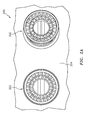
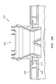
FIGS. 2A-2B illustrate a retention system for a mixer in accordance with aspects of the disclosure. -
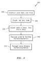
FIG. 3 illustrates a flow chart of an exemplary method in accordance with aspects of the disclosure. -
FIG. 4 illustrates a gas turbine engine. - It is noted that various connections are set forth between elements in the following description and in the drawings (the contents of which are included in this disclosure by way of reference). It is noted that these connections are general and, unless specified otherwise, may be direct or indirect and that this specification is not intended to be limiting in this respect. A coupling between two or more entities may refer to a direct connection or an indirect connection. An indirect connection may incorporate one or more intervening entities.
- In accordance with various aspects of the disclosure, apparatuses, systems and methods are described for retaining a mixer. A panel of, e.g., a bulkhead may be used as part of the mixer retention/sealing, allowing for a reduced packaging envelope. Accordingly, greater flexibility may be obtained in terms of mixer sizing and location. Mixers may be easily replaced in accordance with aspects of the disclosure, thereby reducing costs associated with maintenance.
- Referring to
FIG. 1A , amixer system 100 is shown. Thesystem 100 includesmixers 102. Due to spacing, or lack thereof, forming a sealing surface for themixers 102 in asheet metal liner 104 is not possible. - One or
more retaining rings 106 are shown as being associated with themixers 102. Aretaining ring 106 requires brazing or welding, which represents a manufacturing cost. The brazing or welding also makes themixer 102 inseparable from theliner 104, which makes maintenance and replacement costly. For example, degradation or breakage experienced in theliner 104 and/or one or more of themixers 102 results in the entirety of theliner 104 andmixers 102 having to be disposed of. -
FIG. 1B represents another view of thesystem 100. As shown inFIG. 1B , thesystem 100 includes apanel 108. Thepanel 108 couples to theliner 104 and protects/shields theliner 104 from high temperatures experienced in a combustion chamber (not shown). As shown inFIG. 1B , amixer 102 is coupled to theretaining ring 106 and theliner 104 via one or more lips/flanges 110, such that theflanges 110 are sandwiched/disposed in between theretaining ring 106 and theliner 104. Traversing the stack-up of entities inFIG. 1B in a bottom-to-top direction, the stack-up includes thepanel 108, theliner 104, themixer 102/flanges 110, and theretaining ring 106. InFIGS. 1A-1B thepanel 108 does not play a role in the retention or sealing of themixer 102. - Referring now to
FIGS. 2A-2B , amixer system 200 in accordance with aspects of the disclosure is shown. Thesystem 200 may include one ormore mixers 202. Themixers 202 may be substantially similar to amixers 102 ofFIGS. 1A-1B . For example, themixers 202 may include one or more lips/flanges 210. - As seen in
FIG. 2B , theflanges 210 are sandwiched/disposed in between aliner 204 and apanel 208. Thepanel 208, which may be cast or molded, can be used to incorporate the sealing surface at no added cost. Accordingly, thesystem 200 may have a reduced liner cost relative to thesystem 100 via the elimination of: (1) welding/machining and forming operations, and/or (2) retaining rings (e.g., retaining rings 106). Thesystem 200 may also have a smaller or reduced profile relative to thesystem 100, thereby providing savings in terms of space. Traversing the stack-up of entities inFIG. 2B in a bottom-to-top direction, the stack-up includes thepanel 208, themixer 202/flanges 210, and theliner 204. - Replacement or re-working of the
mixers 202 is easy relative to replacement of themixers 102, as thepanel 208 is bolted on. Themixers 202 may be removed at one or more inspection intervals and do not require a re-working or scrapping of the entirety of theliner 204 and themixers 202 in the event of failure or degradation. In order to replace or service amixer 202, thepanel 208 can be removed, themixer 202 may be accessed or replaced, and then thepanel 208 can be reattached or bolted back on. Similarly, if theliner 204 needs to be scrapped or serviced themixers 202 can be easily decoupled from theliner 204 to enable such operations. - In terms of a coupling between the
panel 208 and themixer 202, the panel 208 (which may correspond to the panel 108) may include a conical surface to accommodate or seat themixer 202. In order to provide for a robust sealing between thepanel 208 and themixer 202, themixer 202 may also be configured (e.g., machined/manufactured) to have a conical shape or geometry to match thepanel 208. Additionally or alternatively, theliner 204 may be configured (e.g., coined/stamped) to have a flat, or planar, surface, allowing thepanel 208 and themixer 202 to be configured with flat, or planar, surfaces as well. In this version the sealing surfaces would be identical such that any orientation (rotated around a vertical axis at the center of the mixer in the orientation ofFIG. 2B ) of themixer 202 to thepanel 208 would provide face to face sealing. This planar sealing surface could be advantageous in ensuring a better seal since sealing would no longer be orientation dependent, and would be at the expense of adding more complexity into the liner forming process. The optimal shape may therefore be a trade of cost, packaging space and required sealing and may be optimized on a case by cases basis. - Referring to
FIG. 3 , a flow chart of amethod 300 is shown. Themethod 300 may be executed for purposes of making a mixer system, such as thesystem 200 described above. - In
block 302, one or more entities may be constructed. For example, a panel, a liner, and/or a mixer may be manufactured, machined, or assembled as part ofblock 302. Theconstruction 302 may adhere to one or more requirements or specifications associated with the system. For example, device tolerances may be taken into consideration as part ofblock 302. - In
block 304, the mixer and the liner may be coupled to one another. The coupling ofblock 304 may result in a lip/flange of the mixer abutting with the liner. - In
block 306, the panel may be coupled (e.g., bolted) to one or more of the mixer, the liner, or a body (e.g., a body of an aircraft). The coupling ofblock 306 may result in a portion of the mixer (e.g., the lip/flange) being sandwiched/disposed between the liner and the panel. - In
block 308, the panel may be decoupled from, e.g., the liner, the mixer or the body of the aircraft.Block 308 may be executed to facilitate maintenance/service activities with respect to, e.g., the liner or the mixer. Such maintenance/service activities may include a repair or replacement of one or more of the liner and the mixer. - In
block 310, the panel may be recoupled to the mixer, the liner or the body subsequent to the maintenance/service activity ofblock 308. - Aspects of the disclosure may be applied in connection with a gas turbine engine. For example,
FIG. 4 is a side-sectional illustration of agas turbine engine 10. Theengine 10 includes acompressor section 12, aturbine section 14 and one or more engine hot sections. The engine hot sections may include, for example, a first enginehot section 16 configured as a combustor section and a second enginehot section 18 configured as an augmentor section. Thecompressor section 12, the first enginehot section 16, theturbine section 14 and the second enginehot section 18 may be sequentially aligned along anaxial centerline 20 between a forwardengine airflow inlet 22 and an aftengine airflow exhaust 24. - Aspects of the disclosure have been described in terms of illustrative embodiments thereof. Numerous other embodiments, modifications, and variations within the scope and spirit of the appended claims will occur to persons of ordinary skill in the art from a review of this disclosure. For example, one of ordinary skill in the art will appreciate that the steps described in conjunction with the illustrative figures may be performed in other than the recited order, and that one or more steps illustrated may be optional in accordance with aspects of the disclosure.
Claims (15)
- A method comprising:coupling a surface of a liner (204) of a gas turbine engine of an aircraft to a fuel/air mixer (202); andcoupling a surface of a panel (208) of the engine to the mixer (202) such that a portion of the mixer (202) is disposed between the liner surface and the panel surface.
- The method of claim 1, further comprising:coupling the panel (208) to the liner (204).
- The method of claim 1 or 2, further comprising:bolting the panel (208) to at least one of the liner (204), the mixer (202), and a body of the aircraft.
- The method of claim 1, 2 or 3, further comprising:decoupling the panel (208) from the mixer (202).
- The method of claim 4, further comprising:servicing at least one of the liner (204) and the mixer (202).
- The method of claim 5, wherein servicing the at least one of the liner (204) and the mixer (202) comprises repairing or replacing the at least one of the liner (204) and the mixer (202).
- The method of claim 5 or 6, further comprising:recoupling the panel (208) subsequent to the servicing.
- The method of any preceding claim, wherein the portion of the mixer (202) that is disposed between the liner (204) and the panel (208) corresponds to a flange (210) of the mixer (202).
- A system comprising:a liner (204) of a gas turbine engine of an aircraft;a panel (208) of the engine; anda fuel/air mixer (202) associated with a combustion chamber of the aircraft,wherein a portion of the mixer (202) is disposed between a surface of the liner (204) and a surface of the panel (208).
- The system of claim 9, wherein the liner (204) comprises sheet metal.
- The system of claim 9 or 10, wherein the panel (208) is at least one of cast and molded.
- The system of claim 9, 10 or 11, wherein the portion of the mixer (202) that is disposed between the liner (204) and the panel (208) comprises a flange (210) of the mixer (202).
- The system of any of claims 9 to 12, wherein the mixer (202) is configured to have a conical shape to match a conical shape of the panel (208).
- The system of any of claims 9 to 13, wherein the liner (204) is configured to have a flat surface, and wherein the panel (208) and the mixer (202) are configured to have flat, circular shapes.
- The system of any of claims 9 to 14, wherein the mixer (202) is a swirler.
Applications Claiming Priority (1)
| Application Number | Priority Date | Filing Date | Title |
|---|---|---|---|
| US201462056978P | 2014-09-29 | 2014-09-29 |
Publications (2)
| Publication Number | Publication Date |
|---|---|
| EP3001107A1 true EP3001107A1 (en) | 2016-03-30 |
| EP3001107B1 EP3001107B1 (en) | 2019-09-04 |
Family
ID=54252057
Family Applications (1)
| Application Number | Title | Priority Date | Filing Date |
|---|---|---|---|
| EP15187480.7A Active EP3001107B1 (en) | 2014-09-29 | 2015-09-29 | Mixer retention |
Country Status (2)
| Country | Link |
|---|---|
| US (1) | US20160116169A1 (en) |
| EP (1) | EP3001107B1 (en) |
Families Citing this family (1)
| Publication number | Priority date | Publication date | Assignee | Title |
|---|---|---|---|---|
| US12130016B1 (en) | 2023-05-31 | 2024-10-29 | General Electric Company | Turbine engine including a combustor |
Citations (6)
| Publication number | Priority date | Publication date | Assignee | Title |
|---|---|---|---|---|
| US2800768A (en) * | 1954-08-19 | 1957-07-30 | United Aircraft Corp | Burner construction |
| GB2287310A (en) * | 1994-03-01 | 1995-09-13 | Rolls Royce Plc | Gas turbine engine combustor heatshield |
| US5894732A (en) * | 1995-03-08 | 1999-04-20 | Bmw Rolls-Royce Gmbh | Heat shield arrangement for a gas turbine combustion chamber |
| US6412272B1 (en) * | 1998-12-29 | 2002-07-02 | United Technologies Corporation | Fuel nozzle guide for gas turbine engine and method of assembly/disassembly |
| US20080115499A1 (en) * | 2006-11-17 | 2008-05-22 | Patel Bhawan B | Combustor heat shield with variable cooling |
| EP2518408A2 (en) * | 2011-04-28 | 2012-10-31 | Rolls-Royce plc | A head part of an annular combustion chamber |
Family Cites Families (5)
| Publication number | Priority date | Publication date | Assignee | Title |
|---|---|---|---|---|
| US4454711A (en) * | 1981-10-29 | 1984-06-19 | Avco Corporation | Self-aligning fuel nozzle assembly |
| US6581386B2 (en) * | 2001-09-29 | 2003-06-24 | General Electric Company | Threaded combustor baffle |
| US20070119052A1 (en) * | 2005-11-28 | 2007-05-31 | General Electric Company | Combustor dome repair method |
| US7721436B2 (en) * | 2005-12-20 | 2010-05-25 | Pratt & Whitney Canada Corp. | Method of manufacturing a metal injection moulded combustor swirler |
| CN101657682B (en) * | 2006-09-14 | 2011-06-15 | 索拉透平公司 | Splash plate dome assembly for a turbine engine |
-
2015
- 2015-09-29 US US14/869,410 patent/US20160116169A1/en not_active Abandoned
- 2015-09-29 EP EP15187480.7A patent/EP3001107B1/en active Active
Patent Citations (6)
| Publication number | Priority date | Publication date | Assignee | Title |
|---|---|---|---|---|
| US2800768A (en) * | 1954-08-19 | 1957-07-30 | United Aircraft Corp | Burner construction |
| GB2287310A (en) * | 1994-03-01 | 1995-09-13 | Rolls Royce Plc | Gas turbine engine combustor heatshield |
| US5894732A (en) * | 1995-03-08 | 1999-04-20 | Bmw Rolls-Royce Gmbh | Heat shield arrangement for a gas turbine combustion chamber |
| US6412272B1 (en) * | 1998-12-29 | 2002-07-02 | United Technologies Corporation | Fuel nozzle guide for gas turbine engine and method of assembly/disassembly |
| US20080115499A1 (en) * | 2006-11-17 | 2008-05-22 | Patel Bhawan B | Combustor heat shield with variable cooling |
| EP2518408A2 (en) * | 2011-04-28 | 2012-10-31 | Rolls-Royce plc | A head part of an annular combustion chamber |
Also Published As
| Publication number | Publication date |
|---|---|
| US20160116169A1 (en) | 2016-04-28 |
| EP3001107B1 (en) | 2019-09-04 |
Similar Documents
| Publication | Publication Date | Title |
|---|---|---|
| US10329956B2 (en) | Multi-function boss for a turbine exhaust case | |
| US11536454B2 (en) | Combustor wall assembly for gas turbine engine | |
| US8206102B2 (en) | Attachment interface for a gas turbine engine composite duct structure | |
| US9656761B2 (en) | Lipskin for a nacelle and methods of making the same | |
| CN101016998A (en) | Turbine engine annular combustion chamber with alternating attachments | |
| EP2589875B1 (en) | injection Apparatus | |
| US10054080B2 (en) | Coil spring hanger for exhaust duct liner | |
| JP2007212130A (en) | Annular combustion chamber of turbomachine | |
| JP6553068B2 (en) | Annular turbomachine combustion chamber | |
| US9670791B2 (en) | Flexible finger seal for sealing a gap between turbine engine components | |
| US20150152788A1 (en) | Gas turbine engine comprising an exhaust cone attached to the exhaust casing | |
| US9399952B2 (en) | Method for assembling a nozzle and an exhaust case of a turbomachine | |
| US9745919B2 (en) | Gas turbine engine exhaust ejector/mixer | |
| EP3001107B1 (en) | Mixer retention | |
| US10273904B2 (en) | Fairing for a mixer of a nozzle of a dual-flow turbomachine | |
| US20240011453A1 (en) | Fastening of an exhaust cone in a turbomachine nozzle | |
| US9732631B2 (en) | Exhaust-gas turbocharger | |
| EP4174290B1 (en) | Support plate for a gas turbine engine casing flange | |
| US11732731B2 (en) | Diffuser and deswirl system with integral tangential onboard injector for engine | |
| GB2544706A (en) | Turbine engine such as, for example, an airplane turbojet or turboprop engine | |
| EP3461999A1 (en) | Contoured case bosses for a gas turbine engine | |
| US10519809B2 (en) | Liner for mounting socket of magnesium housing of aircraft engine | |
| US11999501B2 (en) | Exhaust duct assembly and aircraft including the same | |
| RU199280U1 (en) | TURBO-SCREW ENGINE SUSPENSION HOUSING | |
| WO2020040720A1 (en) | Assembly and method for supporting turbine exhaust diffuser |
Legal Events
| Date | Code | Title | Description |
|---|---|---|---|
| PUAI | Public reference made under article 153(3) epc to a published international application that has entered the european phase |
Free format text: ORIGINAL CODE: 0009012 |
|
| AK | Designated contracting states |
Kind code of ref document: A1 Designated state(s): AL AT BE BG CH CY CZ DE DK EE ES FI FR GB GR HR HU IE IS IT LI LT LU LV MC MK MT NL NO PL PT RO RS SE SI SK SM TR |
|
| AX | Request for extension of the european patent |
Extension state: BA ME |
|
| RAP1 | Party data changed (applicant data changed or rights of an application transferred) |
Owner name: UNITED TECHNOLOGIES CORPORATION |
|
| 17P | Request for examination filed |
Effective date: 20160926 |
|
| RBV | Designated contracting states (corrected) |
Designated state(s): AL AT BE BG CH CY CZ DE DK EE ES FI FR GB GR HR HU IE IS IT LI LT LU LV MC MK MT NL NO PL PT RO RS SE SI SK SM TR |
|
| STAA | Information on the status of an ep patent application or granted ep patent |
Free format text: STATUS: EXAMINATION IS IN PROGRESS |
|
| 17Q | First examination report despatched |
Effective date: 20180705 |
|
| GRAP | Despatch of communication of intention to grant a patent |
Free format text: ORIGINAL CODE: EPIDOSNIGR1 |
|
| STAA | Information on the status of an ep patent application or granted ep patent |
Free format text: STATUS: GRANT OF PATENT IS INTENDED |
|
| INTG | Intention to grant announced |
Effective date: 20190313 |
|
| GRAS | Grant fee paid |
Free format text: ORIGINAL CODE: EPIDOSNIGR3 |
|
| GRAA | (expected) grant |
Free format text: ORIGINAL CODE: 0009210 |
|
| STAA | Information on the status of an ep patent application or granted ep patent |
Free format text: STATUS: THE PATENT HAS BEEN GRANTED |
|
| AK | Designated contracting states |
Kind code of ref document: B1 Designated state(s): AL AT BE BG CH CY CZ DE DK EE ES FI FR GB GR HR HU IE IS IT LI LT LU LV MC MK MT NL NO PL PT RO RS SE SI SK SM TR |
|
| REG | Reference to a national code |
Ref country code: GB Ref legal event code: FG4D |
|
| REG | Reference to a national code |
Ref country code: CH Ref legal event code: EP |
|
| REG | Reference to a national code |
Ref country code: AT Ref legal event code: REF Ref document number: 1175879 Country of ref document: AT Kind code of ref document: T Effective date: 20190915 |
|
| REG | Reference to a national code |
Ref country code: DE Ref legal event code: R096 Ref document number: 602015037071 Country of ref document: DE |
|
| REG | Reference to a national code |
Ref country code: IE Ref legal event code: FG4D |
|
| REG | Reference to a national code |
Ref country code: NL Ref legal event code: MP Effective date: 20190904 |
|
| REG | Reference to a national code |
Ref country code: LT Ref legal event code: MG4D |
|
| PG25 | Lapsed in a contracting state [announced via postgrant information from national office to epo] |
Ref country code: SE Free format text: LAPSE BECAUSE OF FAILURE TO SUBMIT A TRANSLATION OF THE DESCRIPTION OR TO PAY THE FEE WITHIN THE PRESCRIBED TIME-LIMIT Effective date: 20190904 Ref country code: LT Free format text: LAPSE BECAUSE OF FAILURE TO SUBMIT A TRANSLATION OF THE DESCRIPTION OR TO PAY THE FEE WITHIN THE PRESCRIBED TIME-LIMIT Effective date: 20190904 Ref country code: BG Free format text: LAPSE BECAUSE OF FAILURE TO SUBMIT A TRANSLATION OF THE DESCRIPTION OR TO PAY THE FEE WITHIN THE PRESCRIBED TIME-LIMIT Effective date: 20191204 Ref country code: NO Free format text: LAPSE BECAUSE OF FAILURE TO SUBMIT A TRANSLATION OF THE DESCRIPTION OR TO PAY THE FEE WITHIN THE PRESCRIBED TIME-LIMIT Effective date: 20191204 Ref country code: FI Free format text: LAPSE BECAUSE OF FAILURE TO SUBMIT A TRANSLATION OF THE DESCRIPTION OR TO PAY THE FEE WITHIN THE PRESCRIBED TIME-LIMIT Effective date: 20190904 Ref country code: HR Free format text: LAPSE BECAUSE OF FAILURE TO SUBMIT A TRANSLATION OF THE DESCRIPTION OR TO PAY THE FEE WITHIN THE PRESCRIBED TIME-LIMIT Effective date: 20190904 |
|
| PG25 | Lapsed in a contracting state [announced via postgrant information from national office to epo] |
Ref country code: LV Free format text: LAPSE BECAUSE OF FAILURE TO SUBMIT A TRANSLATION OF THE DESCRIPTION OR TO PAY THE FEE WITHIN THE PRESCRIBED TIME-LIMIT Effective date: 20190904 Ref country code: AL Free format text: LAPSE BECAUSE OF FAILURE TO SUBMIT A TRANSLATION OF THE DESCRIPTION OR TO PAY THE FEE WITHIN THE PRESCRIBED TIME-LIMIT Effective date: 20190904 Ref country code: RS Free format text: LAPSE BECAUSE OF FAILURE TO SUBMIT A TRANSLATION OF THE DESCRIPTION OR TO PAY THE FEE WITHIN THE PRESCRIBED TIME-LIMIT Effective date: 20190904 Ref country code: GR Free format text: LAPSE BECAUSE OF FAILURE TO SUBMIT A TRANSLATION OF THE DESCRIPTION OR TO PAY THE FEE WITHIN THE PRESCRIBED TIME-LIMIT Effective date: 20191205 Ref country code: ES Free format text: LAPSE BECAUSE OF FAILURE TO SUBMIT A TRANSLATION OF THE DESCRIPTION OR TO PAY THE FEE WITHIN THE PRESCRIBED TIME-LIMIT Effective date: 20190904 |
|
| REG | Reference to a national code |
Ref country code: AT Ref legal event code: MK05 Ref document number: 1175879 Country of ref document: AT Kind code of ref document: T Effective date: 20190904 |
|
| PG25 | Lapsed in a contracting state [announced via postgrant information from national office to epo] |
Ref country code: AT Free format text: LAPSE BECAUSE OF FAILURE TO SUBMIT A TRANSLATION OF THE DESCRIPTION OR TO PAY THE FEE WITHIN THE PRESCRIBED TIME-LIMIT Effective date: 20190904 Ref country code: PT Free format text: LAPSE BECAUSE OF FAILURE TO SUBMIT A TRANSLATION OF THE DESCRIPTION OR TO PAY THE FEE WITHIN THE PRESCRIBED TIME-LIMIT Effective date: 20200106 Ref country code: PL Free format text: LAPSE BECAUSE OF FAILURE TO SUBMIT A TRANSLATION OF THE DESCRIPTION OR TO PAY THE FEE WITHIN THE PRESCRIBED TIME-LIMIT Effective date: 20190904 Ref country code: IT Free format text: LAPSE BECAUSE OF FAILURE TO SUBMIT A TRANSLATION OF THE DESCRIPTION OR TO PAY THE FEE WITHIN THE PRESCRIBED TIME-LIMIT Effective date: 20190904 Ref country code: EE Free format text: LAPSE BECAUSE OF FAILURE TO SUBMIT A TRANSLATION OF THE DESCRIPTION OR TO PAY THE FEE WITHIN THE PRESCRIBED TIME-LIMIT Effective date: 20190904 Ref country code: RO Free format text: LAPSE BECAUSE OF FAILURE TO SUBMIT A TRANSLATION OF THE DESCRIPTION OR TO PAY THE FEE WITHIN THE PRESCRIBED TIME-LIMIT Effective date: 20190904 Ref country code: NL Free format text: LAPSE BECAUSE OF FAILURE TO SUBMIT A TRANSLATION OF THE DESCRIPTION OR TO PAY THE FEE WITHIN THE PRESCRIBED TIME-LIMIT Effective date: 20190904 |
|
| PG25 | Lapsed in a contracting state [announced via postgrant information from national office to epo] |
Ref country code: CZ Free format text: LAPSE BECAUSE OF FAILURE TO SUBMIT A TRANSLATION OF THE DESCRIPTION OR TO PAY THE FEE WITHIN THE PRESCRIBED TIME-LIMIT Effective date: 20190904 Ref country code: SK Free format text: LAPSE BECAUSE OF FAILURE TO SUBMIT A TRANSLATION OF THE DESCRIPTION OR TO PAY THE FEE WITHIN THE PRESCRIBED TIME-LIMIT Effective date: 20190904 Ref country code: SM Free format text: LAPSE BECAUSE OF FAILURE TO SUBMIT A TRANSLATION OF THE DESCRIPTION OR TO PAY THE FEE WITHIN THE PRESCRIBED TIME-LIMIT Effective date: 20190904 Ref country code: IS Free format text: LAPSE BECAUSE OF FAILURE TO SUBMIT A TRANSLATION OF THE DESCRIPTION OR TO PAY THE FEE WITHIN THE PRESCRIBED TIME-LIMIT Effective date: 20200224 |
|
| REG | Reference to a national code |
Ref country code: CH Ref legal event code: PL |
|
| REG | Reference to a national code |
Ref country code: DE Ref legal event code: R097 Ref document number: 602015037071 Country of ref document: DE |
|
| PLBE | No opposition filed within time limit |
Free format text: ORIGINAL CODE: 0009261 |
|
| STAA | Information on the status of an ep patent application or granted ep patent |
Free format text: STATUS: NO OPPOSITION FILED WITHIN TIME LIMIT |
|
| PG2D | Information on lapse in contracting state deleted |
Ref country code: IS |
|
| PG25 | Lapsed in a contracting state [announced via postgrant information from national office to epo] |
Ref country code: CH Free format text: LAPSE BECAUSE OF NON-PAYMENT OF DUE FEES Effective date: 20190930 Ref country code: LI Free format text: LAPSE BECAUSE OF NON-PAYMENT OF DUE FEES Effective date: 20190930 Ref country code: DK Free format text: LAPSE BECAUSE OF FAILURE TO SUBMIT A TRANSLATION OF THE DESCRIPTION OR TO PAY THE FEE WITHIN THE PRESCRIBED TIME-LIMIT Effective date: 20190904 Ref country code: IE Free format text: LAPSE BECAUSE OF NON-PAYMENT OF DUE FEES Effective date: 20190929 Ref country code: LU Free format text: LAPSE BECAUSE OF NON-PAYMENT OF DUE FEES Effective date: 20190929 Ref country code: IS Free format text: LAPSE BECAUSE OF FAILURE TO SUBMIT A TRANSLATION OF THE DESCRIPTION OR TO PAY THE FEE WITHIN THE PRESCRIBED TIME-LIMIT Effective date: 20200105 |
|
| REG | Reference to a national code |
Ref country code: BE Ref legal event code: MM Effective date: 20190930 |
|
| 26N | No opposition filed |
Effective date: 20200605 |
|
| PG25 | Lapsed in a contracting state [announced via postgrant information from national office to epo] |
Ref country code: BE Free format text: LAPSE BECAUSE OF NON-PAYMENT OF DUE FEES Effective date: 20190930 Ref country code: MC Free format text: LAPSE BECAUSE OF FAILURE TO SUBMIT A TRANSLATION OF THE DESCRIPTION OR TO PAY THE FEE WITHIN THE PRESCRIBED TIME-LIMIT Effective date: 20190904 Ref country code: SI Free format text: LAPSE BECAUSE OF FAILURE TO SUBMIT A TRANSLATION OF THE DESCRIPTION OR TO PAY THE FEE WITHIN THE PRESCRIBED TIME-LIMIT Effective date: 20190904 |
|
| PG25 | Lapsed in a contracting state [announced via postgrant information from national office to epo] |
Ref country code: CY Free format text: LAPSE BECAUSE OF FAILURE TO SUBMIT A TRANSLATION OF THE DESCRIPTION OR TO PAY THE FEE WITHIN THE PRESCRIBED TIME-LIMIT Effective date: 20190904 |
|
| PG25 | Lapsed in a contracting state [announced via postgrant information from national office to epo] |
Ref country code: HU Free format text: LAPSE BECAUSE OF FAILURE TO SUBMIT A TRANSLATION OF THE DESCRIPTION OR TO PAY THE FEE WITHIN THE PRESCRIBED TIME-LIMIT; INVALID AB INITIO Effective date: 20150929 Ref country code: MT Free format text: LAPSE BECAUSE OF FAILURE TO SUBMIT A TRANSLATION OF THE DESCRIPTION OR TO PAY THE FEE WITHIN THE PRESCRIBED TIME-LIMIT Effective date: 20190904 |
|
| PG25 | Lapsed in a contracting state [announced via postgrant information from national office to epo] |
Ref country code: TR Free format text: LAPSE BECAUSE OF FAILURE TO SUBMIT A TRANSLATION OF THE DESCRIPTION OR TO PAY THE FEE WITHIN THE PRESCRIBED TIME-LIMIT Effective date: 20190904 |
|
| PG25 | Lapsed in a contracting state [announced via postgrant information from national office to epo] |
Ref country code: MK Free format text: LAPSE BECAUSE OF FAILURE TO SUBMIT A TRANSLATION OF THE DESCRIPTION OR TO PAY THE FEE WITHIN THE PRESCRIBED TIME-LIMIT Effective date: 20190904 |
|
| REG | Reference to a national code |
Ref country code: DE Ref legal event code: R081 Ref document number: 602015037071 Country of ref document: DE Owner name: RAYTHEON TECHNOLOGIES CORPORATION (N.D.GES.D.S, US Free format text: FORMER OWNER: UNITED TECHNOLOGIES CORPORATION, FARMINGTON, CONN., US Ref country code: DE Ref legal event code: R081 Ref document number: 602015037071 Country of ref document: DE Owner name: RTX CORPORATION (N.D.GES.D. STAATES DELAWARE),, US Free format text: FORMER OWNER: UNITED TECHNOLOGIES CORPORATION, FARMINGTON, CONN., US |
|
| P01 | Opt-out of the competence of the unified patent court (upc) registered |
Effective date: 20230520 |
|
| PGFP | Annual fee paid to national office [announced via postgrant information from national office to epo] |
Ref country code: DE Payment date: 20250820 Year of fee payment: 11 |
|
| PGFP | Annual fee paid to national office [announced via postgrant information from national office to epo] |
Ref country code: GB Payment date: 20250822 Year of fee payment: 11 |
|
| PGFP | Annual fee paid to national office [announced via postgrant information from national office to epo] |
Ref country code: FR Payment date: 20250820 Year of fee payment: 11 |
|
| REG | Reference to a national code |
Ref country code: DE Ref legal event code: R081 Ref document number: 602015037071 Country of ref document: DE Owner name: RTX CORPORATION (N.D.GES.D. STAATES DELAWARE),, US Free format text: FORMER OWNER: RAYTHEON TECHNOLOGIES CORPORATION (N.D.GES.D.STAATES DELAWARE), ARLINGTON, VA, US |