EP3001059A1 - Plug assembly, rolling bearing comprising such plug assembly and machine comprising such rolling bearing - Google Patents
Plug assembly, rolling bearing comprising such plug assembly and machine comprising such rolling bearing Download PDFInfo
- Publication number
- EP3001059A1 EP3001059A1 EP14306521.7A EP14306521A EP3001059A1 EP 3001059 A1 EP3001059 A1 EP 3001059A1 EP 14306521 A EP14306521 A EP 14306521A EP 3001059 A1 EP3001059 A1 EP 3001059A1
- Authority
- EP
- European Patent Office
- Prior art keywords
- plug
- ring
- plug assembly
- rolling bearing
- bearing
- Prior art date
- Legal status (The legal status is an assumption and is not a legal conclusion. Google has not performed a legal analysis and makes no representation as to the accuracy of the status listed.)
- Granted
Links
Images


Classifications
-
- F—MECHANICAL ENGINEERING; LIGHTING; HEATING; WEAPONS; BLASTING
- F16—ENGINEERING ELEMENTS AND UNITS; GENERAL MEASURES FOR PRODUCING AND MAINTAINING EFFECTIVE FUNCTIONING OF MACHINES OR INSTALLATIONS; THERMAL INSULATION IN GENERAL
- F16C—SHAFTS; FLEXIBLE SHAFTS; ELEMENTS OR CRANKSHAFT MECHANISMS; ROTARY BODIES OTHER THAN GEARING ELEMENTS; BEARINGS
- F16C43/00—Assembling bearings
- F16C43/04—Assembling rolling-contact bearings
- F16C43/06—Placing rolling bodies in cages or bearings
-
- F—MECHANICAL ENGINEERING; LIGHTING; HEATING; WEAPONS; BLASTING
- F16—ENGINEERING ELEMENTS AND UNITS; GENERAL MEASURES FOR PRODUCING AND MAINTAINING EFFECTIVE FUNCTIONING OF MACHINES OR INSTALLATIONS; THERMAL INSULATION IN GENERAL
- F16C—SHAFTS; FLEXIBLE SHAFTS; ELEMENTS OR CRANKSHAFT MECHANISMS; ROTARY BODIES OTHER THAN GEARING ELEMENTS; BEARINGS
- F16C19/00—Bearings with rolling contact, for exclusively rotary movement
- F16C19/22—Bearings with rolling contact, for exclusively rotary movement with bearing rollers essentially of the same size in one or more circular rows, e.g. needle bearings
- F16C19/24—Bearings with rolling contact, for exclusively rotary movement with bearing rollers essentially of the same size in one or more circular rows, e.g. needle bearings for radial load mainly
- F16C19/26—Bearings with rolling contact, for exclusively rotary movement with bearing rollers essentially of the same size in one or more circular rows, e.g. needle bearings for radial load mainly with a single row of rollers
-
- F—MECHANICAL ENGINEERING; LIGHTING; HEATING; WEAPONS; BLASTING
- F16—ENGINEERING ELEMENTS AND UNITS; GENERAL MEASURES FOR PRODUCING AND MAINTAINING EFFECTIVE FUNCTIONING OF MACHINES OR INSTALLATIONS; THERMAL INSULATION IN GENERAL
- F16B—DEVICES FOR FASTENING OR SECURING CONSTRUCTIONAL ELEMENTS OR MACHINE PARTS TOGETHER, e.g. NAILS, BOLTS, CIRCLIPS, CLAMPS, CLIPS OR WEDGES; JOINTS OR JOINTING
- F16B37/00—Nuts or like thread-engaging members
- F16B37/14—Cap nuts; Nut caps or bolt caps
-
- F—MECHANICAL ENGINEERING; LIGHTING; HEATING; WEAPONS; BLASTING
- F16—ENGINEERING ELEMENTS AND UNITS; GENERAL MEASURES FOR PRODUCING AND MAINTAINING EFFECTIVE FUNCTIONING OF MACHINES OR INSTALLATIONS; THERMAL INSULATION IN GENERAL
- F16C—SHAFTS; FLEXIBLE SHAFTS; ELEMENTS OR CRANKSHAFT MECHANISMS; ROTARY BODIES OTHER THAN GEARING ELEMENTS; BEARINGS
- F16C19/00—Bearings with rolling contact, for exclusively rotary movement
- F16C19/02—Bearings with rolling contact, for exclusively rotary movement with bearing balls essentially of the same size in one or more circular rows
- F16C19/14—Bearings with rolling contact, for exclusively rotary movement with bearing balls essentially of the same size in one or more circular rows for both radial and axial load
- F16C19/16—Bearings with rolling contact, for exclusively rotary movement with bearing balls essentially of the same size in one or more circular rows for both radial and axial load with a single row of balls
-
- F—MECHANICAL ENGINEERING; LIGHTING; HEATING; WEAPONS; BLASTING
- F16—ENGINEERING ELEMENTS AND UNITS; GENERAL MEASURES FOR PRODUCING AND MAINTAINING EFFECTIVE FUNCTIONING OF MACHINES OR INSTALLATIONS; THERMAL INSULATION IN GENERAL
- F16C—SHAFTS; FLEXIBLE SHAFTS; ELEMENTS OR CRANKSHAFT MECHANISMS; ROTARY BODIES OTHER THAN GEARING ELEMENTS; BEARINGS
- F16C2208/00—Plastics; Synthetic resins, e.g. rubbers
- F16C2208/20—Thermoplastic resins
- F16C2208/36—Polyarylene ether ketones [PAEK], e.g. PEK, PEEK
-
- F—MECHANICAL ENGINEERING; LIGHTING; HEATING; WEAPONS; BLASTING
- F16—ENGINEERING ELEMENTS AND UNITS; GENERAL MEASURES FOR PRODUCING AND MAINTAINING EFFECTIVE FUNCTIONING OF MACHINES OR INSTALLATIONS; THERMAL INSULATION IN GENERAL
- F16C—SHAFTS; FLEXIBLE SHAFTS; ELEMENTS OR CRANKSHAFT MECHANISMS; ROTARY BODIES OTHER THAN GEARING ELEMENTS; BEARINGS
- F16C2300/00—Application independent of particular apparatuses
- F16C2300/10—Application independent of particular apparatuses related to size
- F16C2300/14—Large applications, e.g. bearings having an inner diameter exceeding 500 mm
-
- F—MECHANICAL ENGINEERING; LIGHTING; HEATING; WEAPONS; BLASTING
- F16—ENGINEERING ELEMENTS AND UNITS; GENERAL MEASURES FOR PRODUCING AND MAINTAINING EFFECTIVE FUNCTIONING OF MACHINES OR INSTALLATIONS; THERMAL INSULATION IN GENERAL
- F16C—SHAFTS; FLEXIBLE SHAFTS; ELEMENTS OR CRANKSHAFT MECHANISMS; ROTARY BODIES OTHER THAN GEARING ELEMENTS; BEARINGS
- F16C2360/00—Engines or pumps
- F16C2360/31—Wind motors
Definitions
- the invention relates to rolling bearings, in particular to slewing bearings for submarine applications.
- angular contact rolling bearing including an opening and a plug for closing the opening is disclosed e.g. in the document WO 2012/126529 .
- the invention starts from a plug assembly for a rolling bearing comprising at least a first ring and at least one second ring.
- the first ring could be an inner ring and the second ring could be an outer ring or vice versa.
- the rolling bearing comprises at least one row of rolling elements arranged between the rings.
- the rolling elements could be balls, tapered rollers or cylindrical rollers as well as toroidal rollers.
- the bearing could be formed as an angular contact rolling bearing or as another kind of bearing, in particular slewing bearing.
- the rolling bearing is provided with an opening in one of its rings for inserting rolling elements and for taking out the rolling elements out of the space for maintenance or assembly purposes. The opening is closed with a plug of the plug assembly when the bearing is operating, wherein said plug has an inner end face facing the rolling elements and preferably constituting a part of the raceway and an outer end face opposite to the inner end face.
- the plug assembly further comprises a protective cap shielding the outer end face of the plug from a corrosive environment of the bearing.
- a protective cap shielding the outer end face of the plug from a corrosive environment of the bearing.
- the protective cap is made of polyetheretherketone (PEEK), which is highly resistant to sea water corrosion, cheap and simple in terms of manufacturing.
- PEEK polyetheretherketone
- the surface of the first ring surrounding the opening is preferably recessed such that that the protective cap can be formed in a flush countersunk manner.
- the gasket ring avoids sea water leaking in laterally from the edges of the protective cap.
- the protective cap is fixed by stainless steel bolts on a surface of the first ring surrounding the opening.
- the steel bolts are cheap in price, easy to fasten and unfastened and highly resistant to corrosion.
- the gasket ring is arranged between the stainless steel bolts and the opening and is quenched between the protective cap and the surface of the first ring by a pressing force generated by the stainless steel bolts.
- the plug has an essentially cylindrical outer surface provided with at least one circumferential groove for receiving an O-ring in order to further increase the liquid-tightness of the plug.
- the rolling bearing further comprises a locking pin fitted into a transversal bore of the plug
- at least one O-ring is arranged between the transversal bore and the outer end face of the plug.
- O-rings are arranged on both sides of the transversal bore and the plug.
- the invention also concerns a machine, such as a generator of a tidal power plant, equipped with at least one rolling bearing according to the invention, the rolling bearing comprising at least one plug assembly according to the invention.
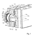
- Fig. 1 is a partial section of a rolling bearing according to the invention.
- the rolling bearing includes a first ring 10 formed as an inner ring and a second ring 12 formed as an outer ring.
- the rolling bearing is a deep-grooved ball bearing (DGBB) with large diameter and each of the rings 10, 12 is provided with deep grooves forming a raceways 10a, 12a for rolling elements 14 such as balls( Figs. 2 and 3 ).
- a lubricant groove 10b, 12b is formed in the bottom of each raceway 10a, 12a respectively.
- DGBB deep-grooved ball bearing
- the toroidal space between the raceways is sealed in both axial directions by suitable sealing rings 16a, 16b collaborating with a ring-shaped insert 16c forming a gliding surface on which the sealing ring 16a, 16b abut respectively.
- the first ring 10 is provided with a bore from the radially inner surface of the first ring 10 to the space between the raceways 10a, 10b.
- the bore is an opening 18 for inserting the rolling elements 14 and suitable spacers (not illustrated) for angularly spacing apart the rolling elements 14 into the space between the raceways 10a, 12a and for taking the rolling elements 14, which are formed as balls, out of the space for maintenance purposes.
- the opening 18 is closed by a plug 20 which is held in place by a slightly conical locking pin 22 fitted through a transversal bore 24 in the plug 20 aligned with corresponding transversal bores in the first ring 10.
- the ends of the bores are sealed with silicone in the embodiment illustrated in Fig. 1 and could be sealed with protective caps in other embodiments.
- the bearing is configured to be used in submarine applications where it is exposed to sea water.
- the plug 20 has an inner end face 20a facing the rolling elements 14 and being a part of the raceway 10a.
- the plug 20 is mounted when the raceway 10a is machined so such that a smooth raceway 10a without steps at the edges of the plug 20 is achieved.
- the material of the plug 20 is identical to the material of the inner ring 10, i.e. the plug is made of bearing steel.
- the outer surface of the rings 10, 12 in contact with sea water are coated with an anti-corrosion coating.
- Fig. 2 is a sectional view of the rolling bearing according to the invention.
- the plug 20 has an outer end face 20b which is opposite to the inner end face 20a and which is flush with the bottom of a recess 26 machined in the radially inner surface of the inner ring 10 and the recess 26 receives a protective cap 28 made of polyetheretherketone (PEEK) for protecting the outer end face 20b of the plug 20 from the corrosive environment of the bearing, i.e. from sea water.
- the protective cap 28 is counter-sunk in the inner surface of the inner ring 10 and fixed to the bottom surface of the recess 26, which is the surface of surrounding the opening 18, by means of stainless steel bolts 30a-30d ( Figs. 1 and 3 ).
- a gasket ring 32 is fitted into a groove in the inner side of the protective cap 28 and pressed against the bottom surface of the recess 26 by the pressure generated by the bolts 30a-30d.
- the gasket ring 32 is arranged between the opening 18 and the bolts 30a-30d, i.e. radially inward with regard to the axis of the opening 18 such as sea water leaking in via the bolts 30a - 30d or via the edges of the protective cap 28 is prevented from reaching the opening 18.
- the plug 20 is further provided with a threaded bore 38 for engagement with a tool for mounting and unmounting the plug.
- the radially outer surfaces of the essentially cylindrical plug 20 are provided with grooves receiving one O-ring 34, 36 respectively, wherein the first one 34 of the O-rings is arranged between the pin 22 and the protective cap 28 and the other O-ring 36 is arranged between the pin 22 and the space receiving the rolling elements 14.
- the assembly procedure for the bearing according to the invention is as follows.
- the rolling elements 14 are inserted together with spacers and grease via the opening 18 which is then closed with the plug 20.
- the plug 20 is fixed by means of the pin 22 and the bores receiving the pin 22 is closed with silicone.
- the protective cap 28 is mounted using the bolts 30a-30d.
- Fig. 3 is a perspective view of a part of the bearing showing the protective cap fixed with the bolts 30a-30d in the assembled configuration.
Landscapes
- Engineering & Computer Science (AREA)
- General Engineering & Computer Science (AREA)
- Mechanical Engineering (AREA)
- Rolling Contact Bearings (AREA)
Description
- The invention relates to rolling bearings, in particular to slewing bearings for submarine applications.
- It is known to provide large-sized rolling bearings, in particular angular contact rolling bearings formed as slewing bearings with large diameters e.g. for wind turbine applications or applications in construction machinery, with an opening for inserting or removing rolling elements upon assembly or for maintenance works.
- In angular contact rolling bearing including an opening and a plug for closing the opening is disclosed e.g. in the document
WO 2012/126529 . - In recent times, there is an increasing request for large-sized rolling bearings suitable for submarine applications e.g. tidal power plants, oil trilling applications or offshoring parks. As the inner face of the plugs constitutes a part of the raceway of the rolling bearing, the plugs are usually made from bearing steel, which corrodes when exposed to sea water. The corrosion is a problem because it makes the removal of the plug for maintenance purposes difficult and impairs the watertightness of the plug.
- Manufacturing the plug from stainless steel causes further problems because the machining of the raceways, which is usually done in a configuration where the plug is fitted into the opening, becomes difficult and it would be impossible to achieve high quality surface properties for the raceways. Further, a piling up of material on the raceway at the boundary between different material types risks to take place. Finally, the price of plugs manufactured from materials which are resistant to the sea water is very high.
- Further, treating the surface of the plug with nickel-based coatings could work but the coating wears out very rapidly after only a few mounting and unmounting cycles.
- It is therefore the object of the invention to avoid corrosion of a plug in a bearing as described above and, as a consequence, a reduction of the watertightness and the reduction of the lifetime of the rolling bearing resulting from sea water leaking in.
- The invention starts from a plug assembly for a rolling bearing comprising at least a first ring and at least one second ring. The first ring could be an inner ring and the second ring could be an outer ring or vice versa. Further, the rolling bearing comprises at least one row of rolling elements arranged between the rings. The rolling elements could be balls, tapered rollers or cylindrical rollers as well as toroidal rollers. The bearing could be formed as an angular contact rolling bearing or as another kind of bearing, in particular slewing bearing. The rolling bearing is provided with an opening in one of its rings for inserting rolling elements and for taking out the rolling elements out of the space for maintenance or assembly purposes. The opening is closed with a plug of the plug assembly when the bearing is operating, wherein said plug has an inner end face facing the rolling elements and preferably constituting a part of the raceway and an outer end face opposite to the inner end face.
- It is proposed that the plug assembly further comprises a protective cap shielding the outer end face of the plug from a corrosive environment of the bearing. By forming the cap from a material with high corrosion-resistivity a reliable protection of the plug can be achieved and corrosion can be avoided. The mounting and unmounting of the plug remains simple and the watertightness cannot be reduced as a consequence of the corrosion.
- In a preferred embodiment, the protective cap is made of polyetheretherketone (PEEK), which is highly resistant to sea water corrosion, cheap and simple in terms of manufacturing.
- It is further proposed to provide a gasket ring between the protective cap and the surface of the first ring surrounding the opening. The surface of the first ring surrounding the opening is preferably recessed such that that the protective cap can be formed in a flush countersunk manner. The gasket ring avoids sea water leaking in laterally from the edges of the protective cap.
- In a preferred embodiment of the invention, the protective cap is fixed by stainless steel bolts on a surface of the first ring surrounding the opening. The steel bolts are cheap in price, easy to fasten and unfastened and highly resistant to corrosion.
- Preferably, the gasket ring is arranged between the stainless steel bolts and the opening and is quenched between the protective cap and the surface of the first ring by a pressing force generated by the stainless steel bolts.
- Further, it is proposed that the plug has an essentially cylindrical outer surface provided with at least one circumferential groove for receiving an O-ring in order to further increase the liquid-tightness of the plug.
- In particular, an embodiment where the rolling bearing further comprises a locking pin fitted into a transversal bore of the plug, it is preferred that at least one O-ring is arranged between the transversal bore and the outer end face of the plug. As a consequence, sea water leaking in via the lateral bore in the first ring receiving the locking pin is prevented from reaching the raceway. In a most preferred embodiment, O-rings are arranged on both sides of the transversal bore and the plug.
- The invention also concerns a machine, such as a generator of a tidal power plant, equipped with at least one rolling bearing according to the invention, the rolling bearing comprising at least one plug assembly according to the invention.
- The above embodiments of the invention as well as the appended claims and figures show multiple characterizing features of the invention in specific combinations. The skilled person will easily be able to consider further combinations or subcombinations of these features in order to adapt the invention as defined in the claims to his specific needs.
-
- Fig. 1
- is a partial section of a rolling bearing according to the invention;
- Fig. 2
- is a sectional view of the rolling bearing according to the invention; and
- Fig. 3
- is a perspective view of the protective cap in its mounted configuration.
-
Fig. 1 is a partial section of a rolling bearing according to the invention. The rolling bearing includes afirst ring 10 formed as an inner ring and asecond ring 12 formed as an outer ring. The rolling bearing is a deep-grooved ball bearing (DGBB) with large diameter and each of therings raceways rolling elements 14 such as balls(Figs. 2 and3 ). Alubricant groove raceway - The toroidal space between the raceways is sealed in both axial directions by
suitable sealing rings insert 16c forming a gliding surface on which the sealingring - The
first ring 10 is provided with a bore from the radially inner surface of thefirst ring 10 to the space between theraceways opening 18 for inserting therolling elements 14 and suitable spacers (not illustrated) for angularly spacing apart therolling elements 14 into the space between theraceways rolling elements 14, which are formed as balls, out of the space for maintenance purposes. - When the bearing is operating, the
opening 18 is closed by aplug 20 which is held in place by a slightlyconical locking pin 22 fitted through atransversal bore 24 in theplug 20 aligned with corresponding transversal bores in thefirst ring 10. The ends of the bores are sealed with silicone in the embodiment illustrated inFig. 1 and could be sealed with protective caps in other embodiments. - The bearing is configured to be used in submarine applications where it is exposed to sea water.
- The
plug 20 has aninner end face 20a facing therolling elements 14 and being a part of theraceway 10a. Theplug 20 is mounted when theraceway 10a is machined so such that asmooth raceway 10a without steps at the edges of theplug 20 is achieved. The material of theplug 20 is identical to the material of theinner ring 10, i.e. the plug is made of bearing steel. The outer surface of therings -
Fig. 2 is a sectional view of the rolling bearing according to the invention. - The
plug 20 has anouter end face 20b which is opposite to theinner end face 20a and which is flush with the bottom of arecess 26 machined in the radially inner surface of theinner ring 10 and therecess 26 receives aprotective cap 28 made of polyetheretherketone (PEEK) for protecting theouter end face 20b of theplug 20 from the corrosive environment of the bearing, i.e. from sea water. Theprotective cap 28 is counter-sunk in the inner surface of theinner ring 10 and fixed to the bottom surface of therecess 26, which is the surface of surrounding the opening 18, by means ofstainless steel bolts 30a-30d (Figs. 1 and3 ). - A
gasket ring 32 is fitted into a groove in the inner side of theprotective cap 28 and pressed against the bottom surface of therecess 26 by the pressure generated by thebolts 30a-30d. Thegasket ring 32 is arranged between the opening 18 and thebolts 30a-30d, i.e. radially inward with regard to the axis of the opening 18 such as sea water leaking in via thebolts 30a - 30d or via the edges of theprotective cap 28 is prevented from reaching the opening 18. - The
plug 20 is further provided with a threadedbore 38 for engagement with a tool for mounting and unmounting the plug. - Further, the radially outer surfaces of the essentially
cylindrical plug 20 are provided with grooves receiving one O-ring first one 34 of the O-rings is arranged between thepin 22 and theprotective cap 28 and the other O-ring 36 is arranged between thepin 22 and the space receiving the rollingelements 14. - The assembly procedure for the bearing according to the invention is as follows. The rolling
elements 14 are inserted together with spacers and grease via theopening 18 which is then closed with theplug 20. Theplug 20 is fixed by means of thepin 22 and the bores receiving thepin 22 is closed with silicone. Then, theprotective cap 28 is mounted using thebolts 30a-30d. -
Fig. 3 is a perspective view of a part of the bearing showing the protective cap fixed with thebolts 30a-30d in the assembled configuration.
Claims (11)
- Plug assembly for use in a rolling bearing comprising at least a first ring (10), at least one second ring (12), and at least one row of rolling elements (14) arranged between the rings (10, 12), wherein the first ring (10) is provided with an opening (18) for inserting the rolling elements (14) into a space between raceways (10a, 12a) of the rings (10, 12) or for taking said rolling elements (14) out of the space between the raceways (10a, 12a), the plug assembly comprising a plug (20), wherein the plug (20) is configured to close said opening (18) when the bearing is operating, said plug (18) having an inner end face (20a) facing the rolling elements (14) and configured to form a part of the raceway (10a) and an outer end face (20b) opposite to the inner end face (20a),
characterized in that
the plug assembly further comprises a protective cap (28) shielding the outer end face (20b) of the plug (18) from a corrosive environment of the bearing. - Plug assembly according to claim 1,
characterized in that
the protective cap (28) is made of polyetheretherketone (PEEK). - Plug assembly according to one of the preceding claims,
characterized by
further comprising a gasket ring (32) arranged between the protective cap (28) and a surface of the first ring (10) surrounding the opening (18). - Plug assembly according to one of the preceding claims,
characterized by
further comprising stainless steel bolts (30a - 30d) for fixing the protective cap (28) on a surface of the first ring (10) surrounding the opening (18). - Plug assembly according to claims 3 and 4,
characterized in that
the gasket ring (32) is arranged between the stainless steel bolts (30a - 30d) and the opening (18). - Plug assembly according to one of the preceding claims,
characterized in that
the plug (20) has an essentially cylindrical outer surface provided with at least one circumferential groove for receiving an O-ring (34, 36). - Plug assembly according to one of the preceding claims,
characterized by
further comprising a locking pin (22) to be fitted into a transversal bore (24) of the plug (20), wherein at least one O-ring (36) is arranged between the transversal bore (24) and the inner end face (20a) of the plug (20). - Plug assembly according to one of the preceding claims,
characterized by
further comprising a locking pin (22) to be fitted into a transversal bore (24) of the plug (20), wherein at least one O-ring (36) is arranged between the transversal bore (24) and the outer end face (20b) of the plug (20). - Rolling bearing including at least one plug assembly according to one of the preceding claims.
- Rolling bearing according to claim 9, wherein the rolling bearing is formed as a slewing bearing for submarine applications.
- Machine including at least one rolling bearing according to claim 9 or 10.
Priority Applications (6)
| Application Number | Priority Date | Filing Date | Title |
|---|---|---|---|
| EP14306521.7A EP3001059B1 (en) | 2014-09-29 | 2014-09-29 | Plug assembly, rolling bearing comprising such plug assembly and machine comprising such rolling bearing |
| KR1020150136401A KR20160037798A (en) | 2014-09-29 | 2015-09-25 | Plug assembly, rolling bearing comprising such plug assembly and machine comprising such rolling bearing |
| US14/864,941 US9638259B2 (en) | 2014-09-29 | 2015-09-25 | Plug assembly, rolling bearing comprising such plug assembly and machine comprising such rolling bearing |
| BR102015024904A BR102015024904A2 (en) | 2014-09-29 | 2015-09-28 | cap assembly, rolling bearing comprising such cap assembly and machine comprising such rolling bearing |
| CN202110829497.8A CN113565881A (en) | 2014-09-29 | 2015-09-29 | Plug assembly, rolling bearing comprising such a plug assembly and machine comprising such a rolling bearing |
| CN201510887514.8A CN105465195A (en) | 2014-09-29 | 2015-09-29 | Plug assembly, rolling bearing including such plug assembly and machine thereof |
Applications Claiming Priority (1)
| Application Number | Priority Date | Filing Date | Title |
|---|---|---|---|
| EP14306521.7A EP3001059B1 (en) | 2014-09-29 | 2014-09-29 | Plug assembly, rolling bearing comprising such plug assembly and machine comprising such rolling bearing |
Publications (2)
| Publication Number | Publication Date |
|---|---|
| EP3001059A1 true EP3001059A1 (en) | 2016-03-30 |
| EP3001059B1 EP3001059B1 (en) | 2020-05-06 |
Family
ID=51662026
Family Applications (1)
| Application Number | Title | Priority Date | Filing Date |
|---|---|---|---|
| EP14306521.7A Active EP3001059B1 (en) | 2014-09-29 | 2014-09-29 | Plug assembly, rolling bearing comprising such plug assembly and machine comprising such rolling bearing |
Country Status (5)
| Country | Link |
|---|---|
| US (1) | US9638259B2 (en) |
| EP (1) | EP3001059B1 (en) |
| KR (1) | KR20160037798A (en) |
| CN (2) | CN105465195A (en) |
| BR (1) | BR102015024904A2 (en) |
Families Citing this family (5)
| Publication number | Priority date | Publication date | Assignee | Title |
|---|---|---|---|---|
| US10036412B2 (en) * | 2016-09-13 | 2018-07-31 | Caterpillar Inc. | Counterbore plug |
| DE102018201885A1 (en) * | 2018-02-07 | 2019-08-08 | Aktiebolaget Skf | Sealed storage module |
| US10502264B1 (en) * | 2018-08-22 | 2019-12-10 | General Electric Company | Ball plug retention for slewing ring bearing |
| CN109099066B (en) * | 2018-09-18 | 2020-08-18 | 贵州爱因斯凯轴承科技有限公司 | Easily install and remove bearing |
| CN121676581A (en) * | 2026-02-11 | 2026-03-17 | 洛阳鑫凯轴承科技有限公司 | Crossed roller bearing and assembly method thereof |
Citations (8)
| Publication number | Priority date | Publication date | Assignee | Title |
|---|---|---|---|---|
| US3148922A (en) * | 1960-01-12 | 1964-09-15 | Fmc Corp | Plugging device |
| FR2222897A5 (en) * | 1973-03-20 | 1974-10-18 | Rks | |
| EP0375938A1 (en) * | 1988-12-01 | 1990-07-04 | OMET S.r.l. | Rolling-contact bearing |
| US5184928A (en) * | 1991-04-05 | 1993-02-09 | Nsk Ltd. | Cap for rail mounting hole of linear guide device |
| DE19837579A1 (en) * | 1998-08-19 | 2000-02-24 | Schaeffler Waelzlager Ohg | Rollerbearing of concentric rings and fill-hole stopper uses conical stopper of body and washer with interposed seals plus penetrating pin to position stopper body |
| US6053683A (en) * | 1999-02-04 | 2000-04-25 | Cabiran; Michel Lewis | Threaded seal cap for a connector |
| EP2184227A1 (en) * | 2007-09-28 | 2010-05-12 | Mitsubishi Heavy Industries, Ltd. | Lighting-resisting fastener |
| WO2012126529A1 (en) | 2011-03-24 | 2012-09-27 | Aktiebolaget Skf | Angular contact roller bearing, notably used in a wind turbine |
Family Cites Families (21)
| Publication number | Priority date | Publication date | Assignee | Title |
|---|---|---|---|---|
| US3275391A (en) * | 1964-02-20 | 1966-09-27 | Kaydon Engineering Corp | Roller bearing |
| JPS6095228U (en) * | 1983-12-06 | 1985-06-28 | 日本トムソン株式会社 | Cross roller bearing or cross taper roller bearing |
| JP2535587B2 (en) * | 1988-03-29 | 1996-09-18 | 日本トムソン株式会社 | Thin cross roller bearing |
| JP2511112B2 (en) * | 1988-07-12 | 1996-06-26 | 日本トムソン株式会社 | Lubricator for slewing ring bearing with lid |
| US4906113A (en) * | 1988-07-27 | 1990-03-06 | Quintette Coal Limited | Slew ring bearing |
| US5218764A (en) * | 1989-07-05 | 1993-06-15 | Nippon Thompson Co., Ltd. | Method of manufacturing a rotary bearing assembly having an insertion hole |
| JP2583608B2 (en) * | 1989-07-05 | 1997-02-19 | 日本トムソン株式会社 | Slewing ring bearing with rolling element insertion lid and its processing method |
| US5104239A (en) * | 1991-03-06 | 1992-04-14 | Sague John E | In situ replaceable bearing |
| FR2749624B1 (en) * | 1996-06-07 | 1998-07-10 | Roulements Soc Nouvelle | BEARING WITH RADIAL CONDUIT FOR INTRODUCING THE ROLLING BODIES |
| JP4263993B2 (en) * | 2003-12-19 | 2009-05-13 | 日本トムソン株式会社 | Method for manufacturing cross roller bearing with lid |
| JP5451988B2 (en) * | 2008-05-27 | 2014-03-26 | 日本トムソン株式会社 | Ultra-thin cross roller bearing |
| JP5763292B2 (en) * | 2009-07-27 | 2015-08-12 | Ntn株式会社 | Slewing bearing |
| DE102011017776A1 (en) * | 2011-04-29 | 2012-10-31 | Schaeffler Technologies AG & Co. KG | Bearing with corrosion-protected bearing part |
| US8753015B2 (en) * | 2011-06-03 | 2014-06-17 | Hiwin Technologies Corp. | Crossed-roller bearing |
| CN202510558U (en) * | 2012-03-30 | 2012-10-31 | 亨利安管理咨询(青岛)有限公司 | Slewing bearing used for wind power generation and provided with precision oil groove |
| CN202628787U (en) * | 2012-05-14 | 2012-12-26 | 上海天安轴承有限公司 | Self-lubricating bearing |
| CN102758847A (en) * | 2012-06-25 | 2012-10-31 | 扬州市顺景机械有限公司 | High-strength bearing |
| CN103790969A (en) * | 2012-10-30 | 2014-05-14 | 瓦房店福斯特轴承科技开发有限公司 | Angular contact ball bearing having inner ring provided with oil guiding groove |
| CN203308933U (en) * | 2013-05-06 | 2013-11-27 | 无锡市第二轴承有限公司 | Grease storage outer ring structure of high-speed precision bearing |
| EP2827013B1 (en) * | 2013-07-19 | 2017-10-04 | Aktiebolaget SKF | Slewing bearing with a through-hole and plug |
| DE102014223829A1 (en) * | 2014-11-21 | 2016-05-25 | Aktiebolaget Skf | Seal and bearing assembly with the seal |
-
2014
- 2014-09-29 EP EP14306521.7A patent/EP3001059B1/en active Active
-
2015
- 2015-09-25 US US14/864,941 patent/US9638259B2/en not_active Expired - Fee Related
- 2015-09-25 KR KR1020150136401A patent/KR20160037798A/en not_active Withdrawn
- 2015-09-28 BR BR102015024904A patent/BR102015024904A2/en not_active IP Right Cessation
- 2015-09-29 CN CN201510887514.8A patent/CN105465195A/en active Pending
- 2015-09-29 CN CN202110829497.8A patent/CN113565881A/en active Pending
Patent Citations (8)
| Publication number | Priority date | Publication date | Assignee | Title |
|---|---|---|---|---|
| US3148922A (en) * | 1960-01-12 | 1964-09-15 | Fmc Corp | Plugging device |
| FR2222897A5 (en) * | 1973-03-20 | 1974-10-18 | Rks | |
| EP0375938A1 (en) * | 1988-12-01 | 1990-07-04 | OMET S.r.l. | Rolling-contact bearing |
| US5184928A (en) * | 1991-04-05 | 1993-02-09 | Nsk Ltd. | Cap for rail mounting hole of linear guide device |
| DE19837579A1 (en) * | 1998-08-19 | 2000-02-24 | Schaeffler Waelzlager Ohg | Rollerbearing of concentric rings and fill-hole stopper uses conical stopper of body and washer with interposed seals plus penetrating pin to position stopper body |
| US6053683A (en) * | 1999-02-04 | 2000-04-25 | Cabiran; Michel Lewis | Threaded seal cap for a connector |
| EP2184227A1 (en) * | 2007-09-28 | 2010-05-12 | Mitsubishi Heavy Industries, Ltd. | Lighting-resisting fastener |
| WO2012126529A1 (en) | 2011-03-24 | 2012-09-27 | Aktiebolaget Skf | Angular contact roller bearing, notably used in a wind turbine |
Also Published As
| Publication number | Publication date |
|---|---|
| CN105465195A (en) | 2016-04-06 |
| US20160091025A1 (en) | 2016-03-31 |
| EP3001059B1 (en) | 2020-05-06 |
| BR102015024904A2 (en) | 2016-05-24 |
| US9638259B2 (en) | 2017-05-02 |
| CN113565881A (en) | 2021-10-29 |
| KR20160037798A (en) | 2016-04-06 |
Similar Documents
| Publication | Publication Date | Title |
|---|---|---|
| US9638259B2 (en) | Plug assembly, rolling bearing comprising such plug assembly and machine comprising such rolling bearing | |
| US10948019B2 (en) | Slewing bearing with sealing arrangement | |
| DK2561241T3 (en) | Sealing device for a roller bearing | |
| US9188154B2 (en) | Rolling bearing, notably used in a wind turbine | |
| CN104271970B (en) | For the device for the part that can be rotated each other for supporting energy unit | |
| WO2013021887A1 (en) | Tapered roller bearing and mounting structure therefor | |
| US20150275971A1 (en) | Rolling bearing comprising at least one multipart ring, notably for a wind turbine, and associated mounting method | |
| US20150098668A1 (en) | Bearing assembly with spacer for locating a seal sleeve | |
| EP3001058A1 (en) | Plug assembly, rolling bearing comprising such plug assembly, and machine comprising such rolling bearing | |
| EP4390186A1 (en) | Subsea turbine sealing system | |
| US20160327097A1 (en) | Sealing assembly for a rolling bearing | |
| CN102444673B (en) | For the roller of rolling bearing | |
| EP4303455B1 (en) | Bearing unit with rolling bodies and a co-molded inner ring | |
| CN207864418U (en) | Unilateral bearing | |
| JP2017048875A (en) | Cylindrical roller bearing | |
| UA117185C2 (en) | Axial sliding bearing | |
| RU172152U1 (en) | BALL BEARING RADIALLY THrust DOUBLE ROW | |
| CN201747764U (en) | Omni-directional bearing | |
| RU2347903C2 (en) | Telemetry downhole tool | |
| US20170328412A1 (en) | Bearing ring | |
| RU2774342C2 (en) | Integrated bearing section and method | |
| RU169240U1 (en) | BEARING BALL BEAR RADIALLY THrust TWO-ROW THIN-WALLED | |
| KR102095296B1 (en) | Bearing device for crane and high place works vehicles | |
| RU2681997C2 (en) | Lid assembly for round hole for universal joint bearing | |
| RU67632U1 (en) | WELL DEVICE |
Legal Events
| Date | Code | Title | Description |
|---|---|---|---|
| PUAI | Public reference made under article 153(3) epc to a published international application that has entered the european phase |
Free format text: ORIGINAL CODE: 0009012 |
|
| AK | Designated contracting states |
Kind code of ref document: A1 Designated state(s): AL AT BE BG CH CY CZ DE DK EE ES FI FR GB GR HR HU IE IS IT LI LT LU LV MC MK MT NL NO PL PT RO RS SE SI SK SM TR |
|
| AX | Request for extension of the european patent |
Extension state: BA ME |
|
| 17P | Request for examination filed |
Effective date: 20160926 |
|
| RBV | Designated contracting states (corrected) |
Designated state(s): AL AT BE BG CH CY CZ DE DK EE ES FI FR GB GR HR HU IE IS IT LI LT LU LV MC MK MT NL NO PL PT RO RS SE SI SK SM TR |
|
| STAA | Information on the status of an ep patent application or granted ep patent |
Free format text: STATUS: EXAMINATION IS IN PROGRESS |
|
| 17Q | First examination report despatched |
Effective date: 20181024 |
|
| GRAP | Despatch of communication of intention to grant a patent |
Free format text: ORIGINAL CODE: EPIDOSNIGR1 |
|
| STAA | Information on the status of an ep patent application or granted ep patent |
Free format text: STATUS: GRANT OF PATENT IS INTENDED |
|
| INTG | Intention to grant announced |
Effective date: 20191210 |
|
| GRAS | Grant fee paid |
Free format text: ORIGINAL CODE: EPIDOSNIGR3 |
|
| GRAA | (expected) grant |
Free format text: ORIGINAL CODE: 0009210 |
|
| STAA | Information on the status of an ep patent application or granted ep patent |
Free format text: STATUS: THE PATENT HAS BEEN GRANTED |
|
| AK | Designated contracting states |
Kind code of ref document: B1 Designated state(s): AL AT BE BG CH CY CZ DE DK EE ES FI FR GB GR HR HU IE IS IT LI LT LU LV MC MK MT NL NO PL PT RO RS SE SI SK SM TR |
|
| REG | Reference to a national code |
Ref country code: GB Ref legal event code: FG4D |
|
| REG | Reference to a national code |
Ref country code: CH Ref legal event code: EP Ref country code: AT Ref legal event code: REF Ref document number: 1267226 Country of ref document: AT Kind code of ref document: T Effective date: 20200515 |
|
| REG | Reference to a national code |
Ref country code: DE Ref legal event code: R096 Ref document number: 602014064868 Country of ref document: DE |
|
| REG | Reference to a national code |
Ref country code: IE Ref legal event code: FG4D |
|
| REG | Reference to a national code |
Ref country code: LT Ref legal event code: MG4D |
|
| REG | Reference to a national code |
Ref country code: NL Ref legal event code: MP Effective date: 20200506 |
|
| PG25 | Lapsed in a contracting state [announced via postgrant information from national office to epo] |
Ref country code: SE Free format text: LAPSE BECAUSE OF FAILURE TO SUBMIT A TRANSLATION OF THE DESCRIPTION OR TO PAY THE FEE WITHIN THE PRESCRIBED TIME-LIMIT Effective date: 20200506 Ref country code: FI Free format text: LAPSE BECAUSE OF FAILURE TO SUBMIT A TRANSLATION OF THE DESCRIPTION OR TO PAY THE FEE WITHIN THE PRESCRIBED TIME-LIMIT Effective date: 20200506 Ref country code: PT Free format text: LAPSE BECAUSE OF FAILURE TO SUBMIT A TRANSLATION OF THE DESCRIPTION OR TO PAY THE FEE WITHIN THE PRESCRIBED TIME-LIMIT Effective date: 20200907 Ref country code: NO Free format text: LAPSE BECAUSE OF FAILURE TO SUBMIT A TRANSLATION OF THE DESCRIPTION OR TO PAY THE FEE WITHIN THE PRESCRIBED TIME-LIMIT Effective date: 20200806 Ref country code: IS Free format text: LAPSE BECAUSE OF FAILURE TO SUBMIT A TRANSLATION OF THE DESCRIPTION OR TO PAY THE FEE WITHIN THE PRESCRIBED TIME-LIMIT Effective date: 20200906 Ref country code: LT Free format text: LAPSE BECAUSE OF FAILURE TO SUBMIT A TRANSLATION OF THE DESCRIPTION OR TO PAY THE FEE WITHIN THE PRESCRIBED TIME-LIMIT Effective date: 20200506 Ref country code: GR Free format text: LAPSE BECAUSE OF FAILURE TO SUBMIT A TRANSLATION OF THE DESCRIPTION OR TO PAY THE FEE WITHIN THE PRESCRIBED TIME-LIMIT Effective date: 20200807 |
|
| PG25 | Lapsed in a contracting state [announced via postgrant information from national office to epo] |
Ref country code: BG Free format text: LAPSE BECAUSE OF FAILURE TO SUBMIT A TRANSLATION OF THE DESCRIPTION OR TO PAY THE FEE WITHIN THE PRESCRIBED TIME-LIMIT Effective date: 20200806 Ref country code: HR Free format text: LAPSE BECAUSE OF FAILURE TO SUBMIT A TRANSLATION OF THE DESCRIPTION OR TO PAY THE FEE WITHIN THE PRESCRIBED TIME-LIMIT Effective date: 20200506 Ref country code: LV Free format text: LAPSE BECAUSE OF FAILURE TO SUBMIT A TRANSLATION OF THE DESCRIPTION OR TO PAY THE FEE WITHIN THE PRESCRIBED TIME-LIMIT Effective date: 20200506 Ref country code: RS Free format text: LAPSE BECAUSE OF FAILURE TO SUBMIT A TRANSLATION OF THE DESCRIPTION OR TO PAY THE FEE WITHIN THE PRESCRIBED TIME-LIMIT Effective date: 20200506 |
|
| REG | Reference to a national code |
Ref country code: AT Ref legal event code: MK05 Ref document number: 1267226 Country of ref document: AT Kind code of ref document: T Effective date: 20200506 |
|
| PG25 | Lapsed in a contracting state [announced via postgrant information from national office to epo] |
Ref country code: AL Free format text: LAPSE BECAUSE OF FAILURE TO SUBMIT A TRANSLATION OF THE DESCRIPTION OR TO PAY THE FEE WITHIN THE PRESCRIBED TIME-LIMIT Effective date: 20200506 Ref country code: NL Free format text: LAPSE BECAUSE OF FAILURE TO SUBMIT A TRANSLATION OF THE DESCRIPTION OR TO PAY THE FEE WITHIN THE PRESCRIBED TIME-LIMIT Effective date: 20200506 |
|
| PG25 | Lapsed in a contracting state [announced via postgrant information from national office to epo] |
Ref country code: AT Free format text: LAPSE BECAUSE OF FAILURE TO SUBMIT A TRANSLATION OF THE DESCRIPTION OR TO PAY THE FEE WITHIN THE PRESCRIBED TIME-LIMIT Effective date: 20200506 Ref country code: DK Free format text: LAPSE BECAUSE OF FAILURE TO SUBMIT A TRANSLATION OF THE DESCRIPTION OR TO PAY THE FEE WITHIN THE PRESCRIBED TIME-LIMIT Effective date: 20200506 Ref country code: ES Free format text: LAPSE BECAUSE OF FAILURE TO SUBMIT A TRANSLATION OF THE DESCRIPTION OR TO PAY THE FEE WITHIN THE PRESCRIBED TIME-LIMIT Effective date: 20200506 Ref country code: IT Free format text: LAPSE BECAUSE OF FAILURE TO SUBMIT A TRANSLATION OF THE DESCRIPTION OR TO PAY THE FEE WITHIN THE PRESCRIBED TIME-LIMIT Effective date: 20200506 Ref country code: RO Free format text: LAPSE BECAUSE OF FAILURE TO SUBMIT A TRANSLATION OF THE DESCRIPTION OR TO PAY THE FEE WITHIN THE PRESCRIBED TIME-LIMIT Effective date: 20200506 Ref country code: CZ Free format text: LAPSE BECAUSE OF FAILURE TO SUBMIT A TRANSLATION OF THE DESCRIPTION OR TO PAY THE FEE WITHIN THE PRESCRIBED TIME-LIMIT Effective date: 20200506 Ref country code: SM Free format text: LAPSE BECAUSE OF FAILURE TO SUBMIT A TRANSLATION OF THE DESCRIPTION OR TO PAY THE FEE WITHIN THE PRESCRIBED TIME-LIMIT Effective date: 20200506 Ref country code: EE Free format text: LAPSE BECAUSE OF FAILURE TO SUBMIT A TRANSLATION OF THE DESCRIPTION OR TO PAY THE FEE WITHIN THE PRESCRIBED TIME-LIMIT Effective date: 20200506 |
|
| REG | Reference to a national code |
Ref country code: DE Ref legal event code: R097 Ref document number: 602014064868 Country of ref document: DE |
|
| PG25 | Lapsed in a contracting state [announced via postgrant information from national office to epo] |
Ref country code: SK Free format text: LAPSE BECAUSE OF FAILURE TO SUBMIT A TRANSLATION OF THE DESCRIPTION OR TO PAY THE FEE WITHIN THE PRESCRIBED TIME-LIMIT Effective date: 20200506 Ref country code: PL Free format text: LAPSE BECAUSE OF FAILURE TO SUBMIT A TRANSLATION OF THE DESCRIPTION OR TO PAY THE FEE WITHIN THE PRESCRIBED TIME-LIMIT Effective date: 20200506 |
|
| PLBE | No opposition filed within time limit |
Free format text: ORIGINAL CODE: 0009261 |
|
| STAA | Information on the status of an ep patent application or granted ep patent |
Free format text: STATUS: NO OPPOSITION FILED WITHIN TIME LIMIT |
|
| 26N | No opposition filed |
Effective date: 20210209 |
|
| PG25 | Lapsed in a contracting state [announced via postgrant information from national office to epo] |
Ref country code: MC Free format text: LAPSE BECAUSE OF FAILURE TO SUBMIT A TRANSLATION OF THE DESCRIPTION OR TO PAY THE FEE WITHIN THE PRESCRIBED TIME-LIMIT Effective date: 20200506 |
|
| REG | Reference to a national code |
Ref country code: CH Ref legal event code: PL |
|
| GBPC | Gb: european patent ceased through non-payment of renewal fee |
Effective date: 20200929 |
|
| PG25 | Lapsed in a contracting state [announced via postgrant information from national office to epo] |
Ref country code: SI Free format text: LAPSE BECAUSE OF FAILURE TO SUBMIT A TRANSLATION OF THE DESCRIPTION OR TO PAY THE FEE WITHIN THE PRESCRIBED TIME-LIMIT Effective date: 20200506 |
|
| REG | Reference to a national code |
Ref country code: BE Ref legal event code: MM Effective date: 20200930 |
|
| PG25 | Lapsed in a contracting state [announced via postgrant information from national office to epo] |
Ref country code: LU Free format text: LAPSE BECAUSE OF NON-PAYMENT OF DUE FEES Effective date: 20200929 |
|
| PG25 | Lapsed in a contracting state [announced via postgrant information from national office to epo] |
Ref country code: FR Free format text: LAPSE BECAUSE OF NON-PAYMENT OF DUE FEES Effective date: 20200930 |
|
| PG25 | Lapsed in a contracting state [announced via postgrant information from national office to epo] |
Ref country code: BE Free format text: LAPSE BECAUSE OF NON-PAYMENT OF DUE FEES Effective date: 20200930 Ref country code: CH Free format text: LAPSE BECAUSE OF NON-PAYMENT OF DUE FEES Effective date: 20200930 Ref country code: GB Free format text: LAPSE BECAUSE OF NON-PAYMENT OF DUE FEES Effective date: 20200929 Ref country code: IE Free format text: LAPSE BECAUSE OF NON-PAYMENT OF DUE FEES Effective date: 20200929 Ref country code: LI Free format text: LAPSE BECAUSE OF NON-PAYMENT OF DUE FEES Effective date: 20200930 |
|
| PG25 | Lapsed in a contracting state [announced via postgrant information from national office to epo] |
Ref country code: TR Free format text: LAPSE BECAUSE OF FAILURE TO SUBMIT A TRANSLATION OF THE DESCRIPTION OR TO PAY THE FEE WITHIN THE PRESCRIBED TIME-LIMIT Effective date: 20200506 Ref country code: MT Free format text: LAPSE BECAUSE OF FAILURE TO SUBMIT A TRANSLATION OF THE DESCRIPTION OR TO PAY THE FEE WITHIN THE PRESCRIBED TIME-LIMIT Effective date: 20200506 Ref country code: CY Free format text: LAPSE BECAUSE OF FAILURE TO SUBMIT A TRANSLATION OF THE DESCRIPTION OR TO PAY THE FEE WITHIN THE PRESCRIBED TIME-LIMIT Effective date: 20200506 |
|
| PG25 | Lapsed in a contracting state [announced via postgrant information from national office to epo] |
Ref country code: MK Free format text: LAPSE BECAUSE OF FAILURE TO SUBMIT A TRANSLATION OF THE DESCRIPTION OR TO PAY THE FEE WITHIN THE PRESCRIBED TIME-LIMIT Effective date: 20200506 |
|
| P01 | Opt-out of the competence of the unified patent court (upc) registered |
Effective date: 20230513 |
|
| PGFP | Annual fee paid to national office [announced via postgrant information from national office to epo] |
Ref country code: DE Payment date: 20250926 Year of fee payment: 12 |