EP3001022B1 - A low pressure exhaust gas recirculation system for a combustion engine - Google Patents
A low pressure exhaust gas recirculation system for a combustion engine Download PDFInfo
- Publication number
- EP3001022B1 EP3001022B1 EP14176680.8A EP14176680A EP3001022B1 EP 3001022 B1 EP3001022 B1 EP 3001022B1 EP 14176680 A EP14176680 A EP 14176680A EP 3001022 B1 EP3001022 B1 EP 3001022B1
- Authority
- EP
- European Patent Office
- Prior art keywords
- exhaust gas
- combustion engine
- line
- air
- air blower
- Prior art date
- Legal status (The legal status is an assumption and is not a legal conclusion. Google has not performed a legal analysis and makes no representation as to the accuracy of the status listed.)
- Not-in-force
Links
Images

Classifications
-
- F—MECHANICAL ENGINEERING; LIGHTING; HEATING; WEAPONS; BLASTING
- F02—COMBUSTION ENGINES; HOT-GAS OR COMBUSTION-PRODUCT ENGINE PLANTS
- F02M—SUPPLYING COMBUSTION ENGINES IN GENERAL WITH COMBUSTIBLE MIXTURES OR CONSTITUENTS THEREOF
- F02M26/00—Engine-pertinent apparatus for adding exhaust gases to combustion-air, main fuel or fuel-air mixture, e.g. by exhaust gas recirculation [EGR] systems
- F02M26/13—Arrangement or layout of EGR passages, e.g. in relation to specific engine parts or for incorporation of accessories
- F02M26/35—Arrangement or layout of EGR passages, e.g. in relation to specific engine parts or for incorporation of accessories with means for cleaning or treating the recirculated gases, e.g. catalysts, condensate traps, particle filters or heaters
-
- F—MECHANICAL ENGINEERING; LIGHTING; HEATING; WEAPONS; BLASTING
- F02—COMBUSTION ENGINES; HOT-GAS OR COMBUSTION-PRODUCT ENGINE PLANTS
- F02M—SUPPLYING COMBUSTION ENGINES IN GENERAL WITH COMBUSTIBLE MIXTURES OR CONSTITUENTS THEREOF
- F02M26/00—Engine-pertinent apparatus for adding exhaust gases to combustion-air, main fuel or fuel-air mixture, e.g. by exhaust gas recirculation [EGR] systems
- F02M26/13—Arrangement or layout of EGR passages, e.g. in relation to specific engine parts or for incorporation of accessories
- F02M26/34—Arrangement or layout of EGR passages, e.g. in relation to specific engine parts or for incorporation of accessories with compressors, turbines or the like in the recirculation passage
-
- F—MECHANICAL ENGINEERING; LIGHTING; HEATING; WEAPONS; BLASTING
- F01—MACHINES OR ENGINES IN GENERAL; ENGINE PLANTS IN GENERAL; STEAM ENGINES
- F01N—GAS-FLOW SILENCERS OR EXHAUST APPARATUS FOR MACHINES OR ENGINES IN GENERAL; GAS-FLOW SILENCERS OR EXHAUST APPARATUS FOR INTERNAL-COMBUSTION ENGINES
- F01N2230/00—Combination of silencers and other devices
Definitions
- the invention relates to a low pressure exhaust gas recirculation system for a combustion engine and to two methods for operating the system.
- the invention is related to a low pressure exhaust gas recirculation system for a combustion engine according to claim 1 and to a method for operating the system according to claim 10 and the respective dependent claims. Further features of the invention are given in the following description and in the drawings, wherein the features may be important for the invention either alone or in different combinations, without explicitly being notified.
- the invention in a first part relates to a low pressure exhaust gas recirculation system for a combustion engine, preferably for use in a vehicle, at least partially directing an exhaust gas from an exhaust gas line to an air intake line of the combustion engine, wherein the exhaust gas recirculation system comprises first means for actively forwarding the exhaust gas at least partially, and second means for dehumidifying the at least partially forwarded exhaust gas. More specifically, the meaning of "actively forwarding" may include a procedure of conveying and/or pumping the exhaust gas from the exhaust gas line to the air intake line.
- an electrical driven valve in a recirculation pipe between the exhaust gas line and the air intake line may be omitted.
- an electrical driven valve located downstream of a catalyst for example, a SCR catalyst (selective catalytic reduction) or NSC catalyst ("NOx storage catalyst”), may be omitted also.
- NOx emissions NOx means "oxides of nitrogen"
- NOx means "oxides of nitrogen”
- a system control of the recirculation system may be improved, too.
- a functionality of the combustion engine may be improved and component corrosion may be decreased.
- the inventive exhaust gas recirculation system may be constructed simply and may achieve reduced overall costs also.
- the exhaust gas is fed from the exhaust gas line into the first means, then pumped from the first means to the second means, and then conveyed to the air intake line.
- the combustion engine may be a diesel engine, an otto engine (spark ignition engine) or a gas engine.
- the invention may be applied to a natural aspired combustion engine without a turbo charger.
- a high pressure exhaust gas recirculation system may be omitted also.
- the second means is also for cooling the at least partially forwarded exhaust gas. That is, the inventive system advantageously provides cooling and dehumidifying the exhaust gas in a combined way. Furthermore, the first and second means and the muffler are one integrated unit. Therefore, the inventive exhaust gas recirculation system may be arranged in a compact and optionally preassembled unit (that also may be referred as an "integrated muffler system"), so as to reduce space and costs as well.
- the first means for actively forwarding the exhaust gas comprise at least an air blower, preferably driven by an electric motor.
- the inventive system comprises a control means for controlling the speed and/or the sense of rotation of the electric motor. Therefore the air blower may be controlled effectively in at least three modes of operation, however may be driven also in a continuously variable manner.
- the air blower partially forwards the exhaust gas through the recirculation pipe into the air intake line.
- the air blower is driven reversely so as to pump fresh air from the air intake line to the exhaust gas line.
- a NSC catalyst (“NOx storage catalyst"
- NOx storage catalyst may be regenerated by achieving a low air flow as needed.
- an engine operating point may be modified temporarily such that it operates in a rich combustion mode.
- the advantage is to control the flow of a turbocharger in the suction side and not in the high pressure side.
- the air blower is operated in an idle or near-to-idle mode, so as to significantly reduce or even stop the flow of the exhaust gas through the recirculation pipe, taking into account a pressure drop in the recirculation pipe.
- the control means may be integrated in an engine ECU (electronic control unit).
- the exhaust gas is extracted from the exhaust gas line downstream of a muffler.
- the properties of the exhaust gas downstream of the muffler are well conditioned for the inventive principle of actively forwarding the exhaust gas.
- the operation of the low pressure exhaust gas recirculation system may be improved.
- the inventive principle includes several possible locations for extracting the exhaust gas from the exhaust gas line. Preferably downstream of the muffler, but also upstream of the muffler, downstream of a SCR catalyst, or upstream of the SCR catalyst may be possible. Even further configurations along the exhaust gas line may also be used for the inventive principle.
- the exhaust gas is extracted from the exhaust gas line downstream of a selective catalyst. This provides an advantageous option for the inventive system to effectively recirculate the exhaust gas.
- the cooled exhaust gas is fed into the air intake line upstream of a turbo charger and preferably also upstream of an intake air cooler,
- the turbo charger additionally may be driven with the recirculated exhaust gas.
- the intake air cooler of the air intake line additionally may cool the exhaust gas after being mixed with the fresh air from the air intake and after being compressed by the turbo charger.
- the second means for cooling the exhaust gas comprise a controllable bypass for the exhaust gas flow.
- a temperature of the recirculated exhaust gas may be controlled independently of a mass flow and of an operation of the air blower.
- the invention in a second part relates to a method for operating a low pressure exhaust gas recirculation system for a combustion engine, preferably for use in a vehicle, according to any of the foregoing claims, characterized in that a rate of actively forwarded exhaust gas from an exhaust gas line to an air intake line is controlled by modifying a speed and/or a blowing sense of an air blower. Therefore, the system may be operated in a simple and reliable way using well known techniques of controlling an electric motor of the air blower.
- the air blower is regulated depending on an operating state of the combustion engine and/or of an exhaust gas equipment and/or of the vehicle. As a result, an additional reduction of emissions may be achieved.
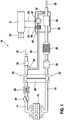
- Figure 1 shows a simplified arrangement of a low pressure exhaust gas recirculation system 10 for a combustion engine 12 of a vehicle (not shown), for at least partially directing or "actively forwarding", respectively, an exhaust gas from an exhaust gas line 16 to an air intake line 14.
- the arrangement of figure 1 comprises the combustion engine 12 (left area of the figure), the air intake line 14 (upper area of the figure) and the exhaust gas line 16 (lower area of the figure).
- An intake air flow is marked with an arrow 18, and an exiting exhaust gas flow is marked with an arrow 20.
- the air flow through the air intake line 14 is from the right to the left
- the exhaust gas flow through the exhaust gas line 16 is from the left to the right.
- the combustion engine 12 depicted in figure 1 is a diesel engine, but the inventive solution also may be used for an otto engine (spark ignition engine) or a gas engine.
- the air may flow through a hot film probe 22, a first section 24 (i.e. the compressor section) of a turbo charger 26, an intake air cooler 28 ("inter cooler"), a throttle valve 30, and then into the combustion engine 12.
- a second section 32 i.e. the turbine section
- an oxidation catalyst 34 may be inserted in the exhaust gas line 16 downstream of the diesel particulate filter 36 and upstream of the muffler 38.
- the muffler 38 is a component of an integrated unit 40 ("integrated muffler system").
- integrated muffler system The exhaust gas line 16, the second section 32 of the turbo charger 26, the oxidation catalyst 34, the diesel particulate filter 36 and the integrated unit 40 may generally be referred to as an "exhaust gas equipment" of the vehicle.
- Component 34 may be an oxidation catalyst or a NSC ("NOx storage catalyst").
- Component 36 may be a diesel particulate filter or a diesel particulate filter plus/or a SCR catalyst.
- the integrated unit 40 comprises the muffler 38, first means 42 for actively forwarding (i.e., conveying or pumping) the exhaust gas at least partially from downstream of the muffler 38, and second means 44 for dehumidifying (and, in an alternative embodiment, also for cooling) the at least partially forwarded exhaust gas.
- the arrangement comprises a recirculation pipe 46, that is a pipeline used for an interconnection between an access or port 48 of the integrated unit 40 and a branch connection 50 at the air intake line 14, being located upstream of the first section 24 of the turbo charger 26.
- said first means 42 are connected to the exhaust gas line 16 at a branch connection 52 downstream of the muffler 38, and on the other hand, the first means 42 are connected to said second means 44.
- the second means 44 are connected via said access 48 of the integrated unit 40 to the recirculation pipe 46.
- the first means 42 for actively forwarding the exhaust gas comprise an air blower, preferably driven by an electric motor (not shown).
- the second means 44 comprise a cooler (preferably an air-air-cooler) and a condenser for dehumidifying the at least partially forwarded exhaust gas.
- the exhaust gas recirculation system 10 comprises control means 51 to provide control of the first means 42, the second means 44, and further elements of the exhaust gas recirculation system 10 and/or of the combustion engine 12. Some control lines to the respective elements symbolically are marked with arrows 53.
- the control means 51 may be integrated in an ECU (engine control unit).
- the exhaust gas line 16 comprises, beginning from the combustion engine 12: the second section 32 of the turbo charger 26, the oxidation catalyst 34, the diesel particulate filter 36, an SCR catalyst (selective catalytic reduction, used for reduction of NOx emissions) and the muffler 38.
- the branch connection 52 for providing a part of the exhaust gas to said first means 42 is located at the exhaust gas line 16 between the diesel particulate filter 36 and the SCR catalyst.
- the second means 44 are connected to the first means 42 and to the air intake line 14 via the branch connection 50 as already described with figure 1 .
- a flow rate of said part of the exhaust gas preferably is controlled by modifying a speed and/or a blowing sense of the air blower. That is, a mass flow of the recirculated exhaust gas conveyed through the recirculation pipe 46 may be varied. In particular said mass flow may significantly be increased with respect to systems having no means for actively forwarding the exhaust gas. Thus, the operation of the combustion engine 12 may be improved and certain emissions in the exhaust gas may be decreased.
- the air blower is regulated depending on an operating state of the combustion engine 12 and/or of the exhaust gas equipment and/or of the vehicle.
- the air blower preferably is driven in a way that the exhaust gas is forwarded from the exhaust gas line 16 to the air intake line 14 as depicted by the triangle in the drawing symbol of the first means 42 in figure 1 .
- the air blower at least temporarily is operated in a way that a reverse air flow is achieved from the air intake line 14 to the exhaust gas line 16. That is, fresh air can be provided from the upstream side of the first section 24 of the turbo charger 26 via branch connection 50 to the exhaust gas line 16 for creating the condition for NOx selective catalytic rich mode regeneration combustion (lambda preferably below a value of "1").
- the advantage is to control the charger flow in the suction side and not in the high pressure side of the air intake line 14. With respect to the latter case the throttle valve 30 at least partially may be closed. Therefore a possible overload of the turbo charger 26 may be reduced or even be avoided.
- the same alternative mode of operation may be applied to the "alternative embodiment" (see above), wherein the exhaust gas preferably is fed into the exhaust gas line 16 downstream of the SCR catalyst.
- the integrated unit 40 is operated independently from an operating state of the combustion engine 12, therefore a required exhaust gas flow rate is decoupled from the engine operating point itself.
- the air blower may be operated independently from the operating state of the combustion engine 12.
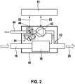
- FIG. 2 presents an additional view of the integrated unit 40 of figure 1 , wherein the second means 44 additionally comprise a controllable bypass 54 for optionally bypassing a part of the exhaust gas flow at the second means 44.
- the second means 44 Downstream from the muffler 38 (“silencer") the exhaust gas partially is provided from the exhaust gas line 16 via the branch connection 52 to the air blower.
- the air blower may be realized by an electrical fan or by any other suitable type of a gas conveying machine, e.g. a centrifugal blower.
- the second means 44 are used for cooling down the exhaust gas flow and to separate the condensating water.
- the control means 51 also are depicted in figure 2 , now additionally providing control for the bypass 54.
- a desired temperature of the exhaust gas flow therefore may be controlled by the controllable bypass 54.
- the bypass 54 is realized by "active flaps" of the cooler in the second means 44.
- Figure 3 shows a psychrometric diagram for sea-level elevation describing several dependencies of physical variables.
- the physical variables are: a dry bulb temperature 60 (on a horizontal line at the bottom of the diagram), an absolute humidity 62 (on a vertical line rightmost on the diagram, scaled from 0 to 30), a relative humidity 64 (see the leftmost arrow on the diagram, scaled from 0% to 100%), an enthalpy 66 at saturation (scaled from 20 to 100), a saturation temperature 68 (scaled from 0 to 30, unit is °C), and a specific volume 70 (scaled from 0.80 to 0.95).
- a first elliptic area 72 denotes an area of operation related to conventional systems.
- a second elliptic area 74 denotes an area of operation being possible with the inventive exhaust gas recirculation system 10.
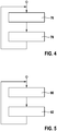
- Figure 4 shows a first flowchart of a method for operating the low pressure exhaust gas recirculation system 10 for a combustion engine 12 of a vehicle.
- a first block 76 an operating state of the combustion engine 12 and the related exhaust gas equipment and the vehicle are determined.
- the rate of the actively forwarded exhaust gas from the exhaust gas line 16 to the air intake line 14 is controlled by modifying a speed and/or a blowing sense of the air blower, that is, the air blower is regulated.
- Figure 5 shows a second flowchart of a method for operating the low pressure exhaust gas recirculation system 10.
- the system 10 is operated according to the procedure described with figure 4 .
- the air blower at least temporarily is operated in a way that a reverse air flow is achieved from the air intake line 14 to the exhaust gas line 16, fed into the exhaust gas line upstream or downstream (dependent on an embodiment) of a SCR catalyst.
- Different catalyst configurations may be possible.
- component 34 may be an oxidation catalyst or a NSC
- component 36 may be a diesel particulate filter or a diesel particulate filter plus/or a SCR catalyst. Therefore a regeneration of the NSC catalyst is possible, applying a rich combustion mode, wherein a low air flow is required in the air intake line 14. After regeneration the method returns to block 80.
Landscapes
- Engineering & Computer Science (AREA)
- Chemical & Material Sciences (AREA)
- Combustion & Propulsion (AREA)
- Mechanical Engineering (AREA)
- General Engineering & Computer Science (AREA)
- Chemical Kinetics & Catalysis (AREA)
- Exhaust-Gas Circulating Devices (AREA)
- Exhaust Gas After Treatment (AREA)
Description
- The invention relates to a low pressure exhaust gas recirculation system for a combustion engine and to two methods for operating the system.
- It is known in prior art to recirculate an exhaust gas of a combustion engine at least partially. Two methods are known in general: First, a recirculation of the exhaust gas in the vicinity of insets and outlets of the combustion engine, i.e., a high pressure recirculation. Second, a recirculation of the exhaust gas rather in the vicinity of an exhaust gas exit or an air intake, respectively. This is called a low pressure recirculation. To avoid a possible engine damage, it is necessary to decrease the absolute humidity level in a low pressure exhaust gas recirculation system as much as possible. Preferably the recirculated exhaust gas is cooled down along the so-called water vapor saturation curve.
US 2007/0137590 relates to an internal combustion engine / water source system. Other patent disclosures in this technical field areWO 2013/178691 A1 , andJP 2002 332919 A - The invention is related to a low pressure exhaust gas recirculation system for a combustion engine according to claim 1 and to a method for operating the system according to
claim 10 and the respective dependent claims. Further features of the invention are given in the following description and in the drawings, wherein the features may be important for the invention either alone or in different combinations, without explicitly being notified. - In a first part the invention relates to a low pressure exhaust gas recirculation system for a combustion engine, preferably for use in a vehicle, at least partially directing an exhaust gas from an exhaust gas line to an air intake line of the combustion engine, wherein the exhaust gas recirculation system comprises first means for actively forwarding the exhaust gas at least partially, and second means for dehumidifying the at least partially forwarded exhaust gas. More specifically, the meaning of "actively forwarding" may include a procedure of conveying and/or pumping the exhaust gas from the exhaust gas line to the air intake line. By this, several advantages may be achieved: First, an electrical driven valve in a recirculation pipe between the exhaust gas line and the air intake line may be omitted. Second, an electrical driven valve located downstream of a catalyst, for example, a SCR catalyst (selective catalytic reduction) or NSC catalyst ("NOx storage catalyst"), may be omitted also. Moreover, NOx emissions (NOx means "oxides of nitrogen") may be reduced significantly due to higher possible flow rates in the recirculation pipe. Almost independent with regard to a length of the recirculation pipe, possible problems related to condensing the exhaust gas could be minimized, especially in a cold engine phase. Further, a system control of the recirculation system may be improved, too. Overall, a functionality of the combustion engine may be improved and component corrosion may be decreased. The inventive exhaust gas recirculation system may be constructed simply and may achieve reduced overall costs also. Preferably the exhaust gas is fed from the exhaust gas line into the first means, then pumped from the first means to the second means, and then conveyed to the air intake line. The combustion engine may be a diesel engine, an otto engine (spark ignition engine) or a gas engine. In an embodiment the invention may be applied to a natural aspired combustion engine without a turbo charger. A high pressure exhaust gas recirculation system may be omitted also.
- According to the invention, the second means is also for cooling the at least partially forwarded exhaust gas. That is, the inventive system advantageously provides cooling and dehumidifying the exhaust gas in a combined way. Furthermore, the first and second means and the muffler are one integrated unit. Therefore, the inventive exhaust gas recirculation system may be arranged in a compact and optionally preassembled unit (that also may be referred as an "integrated muffler system"), so as to reduce space and costs as well.
- In an embodiment, the first means for actively forwarding the exhaust gas comprise at least an air blower, preferably driven by an electric motor. By this, a relative simple and robust solution for forwarding the exhaust gas may be realized.
- In a further embodiment the inventive system comprises a control means for controlling the speed and/or the sense of rotation of the electric motor. Therefore the air blower may be controlled effectively in at least three modes of operation, however may be driven also in a continuously variable manner. In a normal mode, the air blower partially forwards the exhaust gas through the recirculation pipe into the air intake line. In a regeneration mode, the air blower is driven reversely so as to pump fresh air from the air intake line to the exhaust gas line. By this, a NSC catalyst ("NOx storage catalyst") may be regenerated by achieving a low air flow as needed. During regeneration, an engine operating point may be modified temporarily such that it operates in a rich combustion mode. The advantage is to control the flow of a turbocharger in the suction side and not in the high pressure side. In a third mode, the air blower is operated in an idle or near-to-idle mode, so as to significantly reduce or even stop the flow of the exhaust gas through the recirculation pipe, taking into account a pressure drop in the recirculation pipe. The control means may be integrated in an engine ECU (electronic control unit).
- In a further embodiment the exhaust gas is extracted from the exhaust gas line downstream of a muffler. The properties of the exhaust gas downstream of the muffler are well conditioned for the inventive principle of actively forwarding the exhaust gas. Thus, the operation of the low pressure exhaust gas recirculation system may be improved.
- The inventive principle includes several possible locations for extracting the exhaust gas from the exhaust gas line. Preferably downstream of the muffler, but also upstream of the muffler, downstream of a SCR catalyst, or upstream of the SCR catalyst may be possible. Even further configurations along the exhaust gas line may also be used for the inventive principle.
- In a further embodiment the exhaust gas is extracted from the exhaust gas line downstream of a selective catalyst. This provides an advantageous option for the inventive system to effectively recirculate the exhaust gas.
- In a further embodiment the cooled exhaust gas is fed into the air intake line upstream of a turbo charger and preferably also upstream of an intake air cooler, By this, the turbo charger additionally may be driven with the recirculated exhaust gas. Thus, the so called "turbo lag effect" may be reduced. The intake air cooler of the air intake line additionally may cool the exhaust gas after being mixed with the fresh air from the air intake and after being compressed by the turbo charger.
- A further advantageous option is achieved if the second means for cooling the exhaust gas comprise a controllable bypass for the exhaust gas flow. By this, a temperature of the recirculated exhaust gas may be controlled independently of a mass flow and of an operation of the air blower.
- In a second part the invention relates to a method for operating a low pressure exhaust gas recirculation system for a combustion engine, preferably for use in a vehicle, according to any of the foregoing claims, characterized in that a rate of actively forwarded exhaust gas from an exhaust gas line to an air intake line is controlled by modifying a speed and/or a blowing sense of an air blower. Therefore, the system may be operated in a simple and reliable way using well known techniques of controlling an electric motor of the air blower.
- In an embodiment the air blower is regulated depending on an operating state of the combustion engine and/or of an exhaust gas equipment and/or of the vehicle. As a result, an additional reduction of emissions may be achieved.
- Further embodiments of the present invention are described in more detail with respect to the enclosed figures, wherein
- Figure 1
- shows a schematic drawing of a combustion engine together with an air intake line, an exhaust gas line and a recirculation path;
- Figure 2
- shows an integrated muffler system of the exhaust gas line of
figure 1 in more detail; - Figure 3
- shows a psychrometric diagram for sea-level elevation;
- Figure 4
- shows a first flowchart of a method for operating a low pressure exhaust gas recirculation system for a combustion engine; and
- Figure 5
- shows a second flowchart of a method for operating the low pressure exhaust gas recirculation system.
- Functionally equal or similar elements are denoted with equal or similar reference signs, wherein a repetition of the explanation of these elements mostly is omitted.
-
Figure 1 shows a simplified arrangement of a low pressure exhaustgas recirculation system 10 for acombustion engine 12 of a vehicle (not shown), for at least partially directing or "actively forwarding", respectively, an exhaust gas from anexhaust gas line 16 to anair intake line 14. The arrangement offigure 1 comprises the combustion engine 12 (left area of the figure), the air intake line 14 (upper area of the figure) and the exhaust gas line 16 (lower area of the figure). An intake air flow is marked with anarrow 18, and an exiting exhaust gas flow is marked with anarrow 20. Infigure 1 in general, the air flow through theair intake line 14 is from the right to the left, and the exhaust gas flow through theexhaust gas line 16 is from the left to the right. Thecombustion engine 12 depicted infigure 1 is a diesel engine, but the inventive solution also may be used for an otto engine (spark ignition engine) or a gas engine. - In the
air intake line 14, beginning from the air intake, the air may flow through ahot film probe 22, a first section 24 (i.e. the compressor section) of aturbo charger 26, an intake air cooler 28 ("inter cooler"), athrottle valve 30, and then into thecombustion engine 12. In theexhaust gas line 16, beginning from thecombustion engine 12, the exhaust gas may flow through a second section 32 (i.e. the turbine section) of theturbo charger 26, anoxidation catalyst 34, adiesel particulate filter 36, amuffler 38, and then to the exhaust gas exit ("environment emission"). Optionally a SCR catalyst ("selective catalytic reduction") may be inserted in theexhaust gas line 16 downstream of thediesel particulate filter 36 and upstream of themuffler 38. - In the present arrangement of
figure 1 themuffler 38 is a component of an integrated unit 40 ("integrated muffler system"). Theexhaust gas line 16, thesecond section 32 of theturbo charger 26, theoxidation catalyst 34, thediesel particulate filter 36 and theintegrated unit 40 may generally be referred to as an "exhaust gas equipment" of the vehicle.Component 34 may be an oxidation catalyst or a NSC ("NOx storage catalyst").Component 36 may be a diesel particulate filter or a diesel particulate filter plus/or a SCR catalyst. - The
integrated unit 40 comprises themuffler 38, first means 42 for actively forwarding (i.e., conveying or pumping) the exhaust gas at least partially from downstream of themuffler 38, and second means 44 for dehumidifying (and, in an alternative embodiment, also for cooling) the at least partially forwarded exhaust gas. Further, the arrangement comprises arecirculation pipe 46, that is a pipeline used for an interconnection between an access orport 48 of theintegrated unit 40 and abranch connection 50 at theair intake line 14, being located upstream of thefirst section 24 of theturbo charger 26. - On one hand, said first means 42 are connected to the
exhaust gas line 16 at abranch connection 52 downstream of themuffler 38, and on the other hand, the first means 42 are connected to said second means 44. The second means 44, on the other hand, are connected via saidaccess 48 of theintegrated unit 40 to therecirculation pipe 46. In the arrangement offigure 1 the first means 42 for actively forwarding the exhaust gas comprise an air blower, preferably driven by an electric motor (not shown). The second means 44 comprise a cooler (preferably an air-air-cooler) and a condenser for dehumidifying the at least partially forwarded exhaust gas. - Further, the exhaust
gas recirculation system 10 comprises control means 51 to provide control of the first means 42, the second means 44, and further elements of the exhaustgas recirculation system 10 and/or of thecombustion engine 12. Some control lines to the respective elements symbolically are marked witharrows 53. The control means 51 may be integrated in an ECU (engine control unit). - In an alternative embodiment (not depicted) the
exhaust gas line 16 comprises, beginning from the combustion engine 12: thesecond section 32 of theturbo charger 26, theoxidation catalyst 34, thediesel particulate filter 36, an SCR catalyst (selective catalytic reduction, used for reduction of NOx emissions) and themuffler 38. Thebranch connection 52 for providing a part of the exhaust gas to said first means 42 is located at theexhaust gas line 16 between thediesel particulate filter 36 and the SCR catalyst. The second means 44 are connected to the first means 42 and to theair intake line 14 via thebranch connection 50 as already described withfigure 1 . - Returning back to
figure 1 , when thecombustion engine 12 is operated, fresh air is sucked at the air intake, compressed by thefirst section 24 of theturbocharger 26 and is fed to an inlet of thecombustion engine 12. As well an exhaust gas generated by thecombustion engine 12 is fed through theexhaust gas line 16 to the exhaust gas exit. Theturbo charger 26 is operated normally. At theintegrated unit 40, a part of the exhaust gas of theexhaust gas line 16 is branched via thebranch connection 52 to the air blower of thefirst means 42. Said part of the exhaust gas is forwarded from the air blower to thesecond means 44. After cooling and dehumidifying/condensing, the part of the exhaust gas is fed via therecirculation pipe 46 into theair intake line 14. A mixture of fresh air (from the air intake) and dehumidified and cooled recirculated exhaust gas (from the recirculation pipe 46) are compressed by thefirst section 24 of theturbo charger 26 and cooled again in the cooler 28. - It is to be understood that a flow rate of said part of the exhaust gas preferably is controlled by modifying a speed and/or a blowing sense of the air blower. That is, a mass flow of the recirculated exhaust gas conveyed through the
recirculation pipe 46 may be varied. In particular said mass flow may significantly be increased with respect to systems having no means for actively forwarding the exhaust gas. Thus, the operation of thecombustion engine 12 may be improved and certain emissions in the exhaust gas may be decreased. - Preferably the air blower is regulated depending on an operating state of the
combustion engine 12 and/or of the exhaust gas equipment and/or of the vehicle. The air blower preferably is driven in a way that the exhaust gas is forwarded from theexhaust gas line 16 to theair intake line 14 as depicted by the triangle in the drawing symbol of the first means 42 infigure 1 . - In an alternative mode of operation ("regeneration mode" of a NSC catalyst or a diesel particulate filter) of the low pressure exhaust
gas recirculation system 10, the air blower at least temporarily is operated in a way that a reverse air flow is achieved from theair intake line 14 to theexhaust gas line 16. That is, fresh air can be provided from the upstream side of thefirst section 24 of theturbo charger 26 viabranch connection 50 to theexhaust gas line 16 for creating the condition for NOx selective catalytic rich mode regeneration combustion (lambda preferably below a value of "1"). The advantage is to control the charger flow in the suction side and not in the high pressure side of theair intake line 14. With respect to the latter case thethrottle valve 30 at least partially may be closed. Therefore a possible overload of theturbo charger 26 may be reduced or even be avoided. The same alternative mode of operation may be applied to the "alternative embodiment" (see above), wherein the exhaust gas preferably is fed into theexhaust gas line 16 downstream of the SCR catalyst. - In a further alternative mode of operation the
integrated unit 40 is operated independently from an operating state of thecombustion engine 12, therefore a required exhaust gas flow rate is decoupled from the engine operating point itself. In particular, the air blower may be operated independently from the operating state of thecombustion engine 12. -
Figure 2 presents an additional view of theintegrated unit 40 offigure 1 , wherein the second means 44 additionally comprise acontrollable bypass 54 for optionally bypassing a part of the exhaust gas flow at thesecond means 44. Downstream from the muffler 38 ("silencer") the exhaust gas partially is provided from theexhaust gas line 16 via thebranch connection 52 to the air blower. The air blower may be realized by an electrical fan or by any other suitable type of a gas conveying machine, e.g. a centrifugal blower. The second means 44 are used for cooling down the exhaust gas flow and to separate the condensating water. The control means 51 also are depicted infigure 2 , now additionally providing control for thebypass 54. - Depending on the environmental conditions and an operating point of the
combustion engine 12, a desired temperature of the exhaust gas flow therefore may be controlled by thecontrollable bypass 54. In an embodiment, thebypass 54 is realized by "active flaps" of the cooler in thesecond means 44. -
Figure 3 shows a psychrometric diagram for sea-level elevation describing several dependencies of physical variables. The physical variables are: a dry bulb temperature 60 (on a horizontal line at the bottom of the diagram), an absolute humidity 62 (on a vertical line rightmost on the diagram, scaled from 0 to 30), a relative humidity 64 (see the leftmost arrow on the diagram, scaled from 0% to 100%), anenthalpy 66 at saturation (scaled from 20 to 100), a saturation temperature 68 (scaled from 0 to 30, unit is °C), and a specific volume 70 (scaled from 0.80 to 0.95). A first elliptic area 72 denotes an area of operation related to conventional systems. A secondelliptic area 74 denotes an area of operation being possible with the inventive exhaustgas recirculation system 10. -
Figure 4 shows a first flowchart of a method for operating the low pressure exhaustgas recirculation system 10 for acombustion engine 12 of a vehicle. In afirst block 76 an operating state of thecombustion engine 12 and the related exhaust gas equipment and the vehicle are determined. In a followingblock 78 the rate of the actively forwarded exhaust gas from theexhaust gas line 16 to theair intake line 14 is controlled by modifying a speed and/or a blowing sense of the air blower, that is, the air blower is regulated. -
Figure 5 shows a second flowchart of a method for operating the low pressure exhaustgas recirculation system 10. In ablock 80 thesystem 10 is operated according to the procedure described withfigure 4 . In ablock 82 the air blower at least temporarily is operated in a way that a reverse air flow is achieved from theair intake line 14 to theexhaust gas line 16, fed into the exhaust gas line upstream or downstream (dependent on an embodiment) of a SCR catalyst. Different catalyst configurations may be possible. As already described above,component 34 may be an oxidation catalyst or a NSC, andcomponent 36 may be a diesel particulate filter or a diesel particulate filter plus/or a SCR catalyst. Therefore a regeneration of the NSC catalyst is possible, applying a rich combustion mode, wherein a low air flow is required in theair intake line 14. After regeneration the method returns to block 80.
Claims (11)
- A low pressure exhaust gas recirculation system (10) for a combustion engine (12), preferably for use in a vehicle, at least partially directing an exhaust gas from an exhaust gas line (16) to an air intake line (14) of the combustion engine (12), wherein the exhaust gas recirculation system (10) comprises first means (42) for actively forwarding the exhaust gas at least partially, and second means (44) for dehumidifying the at least partially forwarded exhaust gas, characterized in that the second means (44) is also for cooling the at least partially forwarded exhaust gas, and wherein the first and second means (42, 44) and the muffler (38) are one integrated unit (40).
- The system (10) according to claim 1, wherein the first means (42) for actively forwarding the exhaust gas comprise at least an air blower, preferably driven by an electric motor.
- The system (10) according to claim 2, wherein it comprises a control means (51) for controlling the speed and/or the sense of rotation of the electric motor.
- The system (10) according to any of the foregoing claims, wherein the exhaust gas is extracted from the exhaust gas line (16) downstream of a muffler (38).
- The system (10) according to any of the foregoing claims, wherein the exhaust gas is extracted from the exhaust gas line (16) downstream of a selective catalyst.
- The system (10) according to any of the foregoing claims, wherein the cooled exhaust gas is fed into the air intake line (14) upstream of a turbo charger (26) and preferably also upstream of an intake air cooler (28).
- The system (10) according to any of the foregoing claims, wherein the second means (44) for cooling the exhaust gas comprise a controllable bypass (54) for an exhaust gas flow.
- A method for operating a low pressure exhaust gas recirculation system (10) for a combustion engine (12), preferably for use in a vehicle, according to any of the foregoing claims, characterized in that a rate of actively forwarded exhaust gas from an exhaust gas line (16) to an air intake line (14) is controlled by modifying a blowing sense of an air blower.
- The method according to claim 8, wherein the air blower is regulated depending on an operating state of the combustion engine (12) and/or of an exhaust gas equipment and/or of the vehicle.
- The method according to claim 9, wherein the air blower at least temporarily is operated in a way that a reverse air flow is achieved from the air intake line (14) to the exhaust gas line (16), preferably fed into the exhaust gas line (16) downstream of a selective catalyst.
- The method according to claim 8, wherein the air blower is operated independently from an operating state of the combustion engine (12).
Priority Applications (1)
| Application Number | Priority Date | Filing Date | Title |
|---|---|---|---|
| EP14176680.8A EP3001022B1 (en) | 2014-07-11 | 2014-07-11 | A low pressure exhaust gas recirculation system for a combustion engine |
Applications Claiming Priority (1)
| Application Number | Priority Date | Filing Date | Title |
|---|---|---|---|
| EP14176680.8A EP3001022B1 (en) | 2014-07-11 | 2014-07-11 | A low pressure exhaust gas recirculation system for a combustion engine |
Publications (2)
| Publication Number | Publication Date |
|---|---|
| EP3001022A1 EP3001022A1 (en) | 2016-03-30 |
| EP3001022B1 true EP3001022B1 (en) | 2017-09-06 |
Family
ID=51167748
Family Applications (1)
| Application Number | Title | Priority Date | Filing Date |
|---|---|---|---|
| EP14176680.8A Not-in-force EP3001022B1 (en) | 2014-07-11 | 2014-07-11 | A low pressure exhaust gas recirculation system for a combustion engine |
Country Status (1)
| Country | Link |
|---|---|
| EP (1) | EP3001022B1 (en) |
Families Citing this family (1)
| Publication number | Priority date | Publication date | Assignee | Title |
|---|---|---|---|---|
| CN117108416B (en) * | 2023-09-27 | 2026-03-24 | 中国第一汽车股份有限公司 | Exhaust gas recirculation device, exhaust gas recirculation control method, device and electronic device |
Family Cites Families (5)
| Publication number | Priority date | Publication date | Assignee | Title |
|---|---|---|---|---|
| JPH10306719A (en) * | 1997-05-06 | 1998-11-17 | Mitsubishi Heavy Ind Ltd | Emission control method for reciprocating internal combustion engine provided with egr mechanism, and device for the same |
| JP2002332919A (en) * | 2001-02-26 | 2002-11-22 | Mitsubishi Heavy Ind Ltd | Exhaust gas recirculation system |
| WO2006045488A1 (en) * | 2004-10-25 | 2006-05-04 | Behr Gmbh & Co. Kg | Condenser in a turbo-compressor system and method for operating one such system |
| US20070137590A1 (en) * | 2005-07-11 | 2007-06-21 | Jan Vetrovec | Internal combustion engine/water source system |
| DE102012209286A1 (en) * | 2012-06-01 | 2013-12-05 | Man Diesel & Turbo Se | Internal combustion engine with exhaust charging and exhaust gas recirculation |
-
2014
- 2014-07-11 EP EP14176680.8A patent/EP3001022B1/en not_active Not-in-force
Non-Patent Citations (1)
| Title |
|---|
| None * |
Also Published As
| Publication number | Publication date |
|---|---|
| EP3001022A1 (en) | 2016-03-30 |
Similar Documents
| Publication | Publication Date | Title |
|---|---|---|
| JP4067025B2 (en) | Multistage turbocharger controller | |
| CN204099044U (en) | Boosting explosive motor | |
| CN103930656B (en) | Blow-by air exchange device | |
| CN102619615B (en) | Large turbocharged two-stroke diesel engine with exhaust gas recirculation | |
| CN204572261U (en) | Exhaust gas recirculation cooler and exhaust gas recycling system | |
| US20130333360A1 (en) | Secondary air injection system | |
| US11846257B2 (en) | Engine system with reversible exhaust gas recirculation pump for controlling bypass flow | |
| JP5530239B2 (en) | Two-stage supercharging system having an exhaust gas purification device for an internal combustion engine and method for controlling the same | |
| CN107228004B (en) | Method and system for reducing emissions | |
| US10006332B2 (en) | Engine system and control apparatus and control method for engine system | |
| JP2018021510A (en) | Condensed water suppression device | |
| BRPI1003163A2 (en) | system using supplementary compressor for exhaust gas recirculation (rgd) | |
| JP2007198310A (en) | Exhaust gas purification system for internal combustion engine | |
| CN107035512A (en) | With supercharging in parallel and the operating method that turbine explosive motor can be activated and the explosive motor of the execution type method | |
| JP6357902B2 (en) | Engine exhaust gas recirculation method and exhaust gas recirculation device | |
| JP6611788B2 (en) | Exhaust gas recirculation system for an internal combustion engine and method for operating such an exhaust gas recirculation system | |
| JP2014098324A (en) | Supercharger for engine | |
| CN104471229A (en) | Engine unit with a recirculation line | |
| EP3001022A1 (en) | A low pressure exhaust gas recirculation system for a combustion engine | |
| US20130047604A1 (en) | Internal combustion engine and method for operating internal combustion engine | |
| CN104047702B (en) | Stratified Charge Engine with Turbocharger and pressurizing method thereof | |
| US9458800B2 (en) | Turbo pump | |
| US10890142B2 (en) | Device for controlling the amount of fluid fed to the intake of a supercharged internal-combustion engine equipped with an exhaust gas recirculation circuit and method using same | |
| JP2016003585A (en) | Cooling device for internal combustion engine | |
| EP3115574A1 (en) | A system for treating exhaust gases (ats) and supercharging of an internal combustion engine in particular of an agricultural vehicle and agricultural vehicle comprising the system |
Legal Events
| Date | Code | Title | Description |
|---|---|---|---|
| PUAI | Public reference made under article 153(3) epc to a published international application that has entered the european phase |
Free format text: ORIGINAL CODE: 0009012 |
|
| AK | Designated contracting states |
Kind code of ref document: A1 Designated state(s): AL AT BE BG CH CY CZ DE DK EE ES FI FR GB GR HR HU IE IS IT LI LT LU LV MC MK MT NL NO PL PT RO RS SE SI SK SM TR |
|
| AX | Request for extension of the european patent |
Extension state: BA ME |
|
| 17P | Request for examination filed |
Effective date: 20160930 |
|
| RBV | Designated contracting states (corrected) |
Designated state(s): AL AT BE BG CH CY CZ DE DK EE ES FI FR GB GR HR HU IE IS IT LI LT LU LV MC MK MT NL NO PL PT RO RS SE SI SK SM TR |
|
| GRAP | Despatch of communication of intention to grant a patent |
Free format text: ORIGINAL CODE: EPIDOSNIGR1 |
|
| INTG | Intention to grant announced |
Effective date: 20170317 |
|
| GRAS | Grant fee paid |
Free format text: ORIGINAL CODE: EPIDOSNIGR3 |
|
| GRAA | (expected) grant |
Free format text: ORIGINAL CODE: 0009210 |
|
| AK | Designated contracting states |
Kind code of ref document: B1 Designated state(s): AL AT BE BG CH CY CZ DE DK EE ES FI FR GB GR HR HU IE IS IT LI LT LU LV MC MK MT NL NO PL PT RO RS SE SI SK SM TR |
|
| REG | Reference to a national code |
Ref country code: GB Ref legal event code: FG4D |
|
| REG | Reference to a national code |
Ref country code: CH Ref legal event code: EP Ref country code: AT Ref legal event code: REF Ref document number: 926173 Country of ref document: AT Kind code of ref document: T Effective date: 20170915 |
|
| REG | Reference to a national code |
Ref country code: IE Ref legal event code: FG4D |
|
| REG | Reference to a national code |
Ref country code: DE Ref legal event code: R096 Ref document number: 602014014063 Country of ref document: DE |
|
| REG | Reference to a national code |
Ref country code: NL Ref legal event code: MP Effective date: 20170906 |
|
| REG | Reference to a national code |
Ref country code: LT Ref legal event code: MG4D |
|
| PG25 | Lapsed in a contracting state [announced via postgrant information from national office to epo] |
Ref country code: LT Free format text: LAPSE BECAUSE OF FAILURE TO SUBMIT A TRANSLATION OF THE DESCRIPTION OR TO PAY THE FEE WITHIN THE PRESCRIBED TIME-LIMIT Effective date: 20170906 Ref country code: SE Free format text: LAPSE BECAUSE OF FAILURE TO SUBMIT A TRANSLATION OF THE DESCRIPTION OR TO PAY THE FEE WITHIN THE PRESCRIBED TIME-LIMIT Effective date: 20170906 Ref country code: HR Free format text: LAPSE BECAUSE OF FAILURE TO SUBMIT A TRANSLATION OF THE DESCRIPTION OR TO PAY THE FEE WITHIN THE PRESCRIBED TIME-LIMIT Effective date: 20170906 Ref country code: FI Free format text: LAPSE BECAUSE OF FAILURE TO SUBMIT A TRANSLATION OF THE DESCRIPTION OR TO PAY THE FEE WITHIN THE PRESCRIBED TIME-LIMIT Effective date: 20170906 Ref country code: NO Free format text: LAPSE BECAUSE OF FAILURE TO SUBMIT A TRANSLATION OF THE DESCRIPTION OR TO PAY THE FEE WITHIN THE PRESCRIBED TIME-LIMIT Effective date: 20171206 |
|
| REG | Reference to a national code |
Ref country code: AT Ref legal event code: MK05 Ref document number: 926173 Country of ref document: AT Kind code of ref document: T Effective date: 20170906 |
|
| PG25 | Lapsed in a contracting state [announced via postgrant information from national office to epo] |
Ref country code: ES Free format text: LAPSE BECAUSE OF FAILURE TO SUBMIT A TRANSLATION OF THE DESCRIPTION OR TO PAY THE FEE WITHIN THE PRESCRIBED TIME-LIMIT Effective date: 20170906 Ref country code: BG Free format text: LAPSE BECAUSE OF FAILURE TO SUBMIT A TRANSLATION OF THE DESCRIPTION OR TO PAY THE FEE WITHIN THE PRESCRIBED TIME-LIMIT Effective date: 20171206 Ref country code: GR Free format text: LAPSE BECAUSE OF FAILURE TO SUBMIT A TRANSLATION OF THE DESCRIPTION OR TO PAY THE FEE WITHIN THE PRESCRIBED TIME-LIMIT Effective date: 20171207 Ref country code: RS Free format text: LAPSE BECAUSE OF FAILURE TO SUBMIT A TRANSLATION OF THE DESCRIPTION OR TO PAY THE FEE WITHIN THE PRESCRIBED TIME-LIMIT Effective date: 20170906 Ref country code: LV Free format text: LAPSE BECAUSE OF FAILURE TO SUBMIT A TRANSLATION OF THE DESCRIPTION OR TO PAY THE FEE WITHIN THE PRESCRIBED TIME-LIMIT Effective date: 20170906 |
|
| PG25 | Lapsed in a contracting state [announced via postgrant information from national office to epo] |
Ref country code: NL Free format text: LAPSE BECAUSE OF FAILURE TO SUBMIT A TRANSLATION OF THE DESCRIPTION OR TO PAY THE FEE WITHIN THE PRESCRIBED TIME-LIMIT Effective date: 20170906 |
|
| PG25 | Lapsed in a contracting state [announced via postgrant information from national office to epo] |
Ref country code: RO Free format text: LAPSE BECAUSE OF FAILURE TO SUBMIT A TRANSLATION OF THE DESCRIPTION OR TO PAY THE FEE WITHIN THE PRESCRIBED TIME-LIMIT Effective date: 20170906 Ref country code: CZ Free format text: LAPSE BECAUSE OF FAILURE TO SUBMIT A TRANSLATION OF THE DESCRIPTION OR TO PAY THE FEE WITHIN THE PRESCRIBED TIME-LIMIT Effective date: 20170906 Ref country code: PL Free format text: LAPSE BECAUSE OF FAILURE TO SUBMIT A TRANSLATION OF THE DESCRIPTION OR TO PAY THE FEE WITHIN THE PRESCRIBED TIME-LIMIT Effective date: 20170906 |
|
| PG25 | Lapsed in a contracting state [announced via postgrant information from national office to epo] |
Ref country code: SM Free format text: LAPSE BECAUSE OF FAILURE TO SUBMIT A TRANSLATION OF THE DESCRIPTION OR TO PAY THE FEE WITHIN THE PRESCRIBED TIME-LIMIT Effective date: 20170906 Ref country code: EE Free format text: LAPSE BECAUSE OF FAILURE TO SUBMIT A TRANSLATION OF THE DESCRIPTION OR TO PAY THE FEE WITHIN THE PRESCRIBED TIME-LIMIT Effective date: 20170906 Ref country code: IS Free format text: LAPSE BECAUSE OF FAILURE TO SUBMIT A TRANSLATION OF THE DESCRIPTION OR TO PAY THE FEE WITHIN THE PRESCRIBED TIME-LIMIT Effective date: 20180106 Ref country code: SK Free format text: LAPSE BECAUSE OF FAILURE TO SUBMIT A TRANSLATION OF THE DESCRIPTION OR TO PAY THE FEE WITHIN THE PRESCRIBED TIME-LIMIT Effective date: 20170906 Ref country code: AT Free format text: LAPSE BECAUSE OF FAILURE TO SUBMIT A TRANSLATION OF THE DESCRIPTION OR TO PAY THE FEE WITHIN THE PRESCRIBED TIME-LIMIT Effective date: 20170906 |
|
| REG | Reference to a national code |
Ref country code: DE Ref legal event code: R097 Ref document number: 602014014063 Country of ref document: DE |
|
| PLBE | No opposition filed within time limit |
Free format text: ORIGINAL CODE: 0009261 |
|
| STAA | Information on the status of an ep patent application or granted ep patent |
Free format text: STATUS: NO OPPOSITION FILED WITHIN TIME LIMIT |
|
| PG25 | Lapsed in a contracting state [announced via postgrant information from national office to epo] |
Ref country code: DK Free format text: LAPSE BECAUSE OF FAILURE TO SUBMIT A TRANSLATION OF THE DESCRIPTION OR TO PAY THE FEE WITHIN THE PRESCRIBED TIME-LIMIT Effective date: 20170906 |
|
| 26N | No opposition filed |
Effective date: 20180607 |
|
| PG25 | Lapsed in a contracting state [announced via postgrant information from national office to epo] |
Ref country code: SI Free format text: LAPSE BECAUSE OF FAILURE TO SUBMIT A TRANSLATION OF THE DESCRIPTION OR TO PAY THE FEE WITHIN THE PRESCRIBED TIME-LIMIT Effective date: 20170906 |
|
| REG | Reference to a national code |
Ref country code: CH Ref legal event code: PL |
|
| GBPC | Gb: european patent ceased through non-payment of renewal fee |
Effective date: 20180711 |
|
| PG25 | Lapsed in a contracting state [announced via postgrant information from national office to epo] |
Ref country code: MC Free format text: LAPSE BECAUSE OF FAILURE TO SUBMIT A TRANSLATION OF THE DESCRIPTION OR TO PAY THE FEE WITHIN THE PRESCRIBED TIME-LIMIT Effective date: 20170906 Ref country code: LU Free format text: LAPSE BECAUSE OF NON-PAYMENT OF DUE FEES Effective date: 20180711 |
|
| REG | Reference to a national code |
Ref country code: BE Ref legal event code: MM Effective date: 20180731 |
|
| REG | Reference to a national code |
Ref country code: IE Ref legal event code: MM4A |
|
| PG25 | Lapsed in a contracting state [announced via postgrant information from national office to epo] |
Ref country code: CH Free format text: LAPSE BECAUSE OF NON-PAYMENT OF DUE FEES Effective date: 20180731 Ref country code: FR Free format text: LAPSE BECAUSE OF NON-PAYMENT OF DUE FEES Effective date: 20180731 Ref country code: GB Free format text: LAPSE BECAUSE OF NON-PAYMENT OF DUE FEES Effective date: 20180711 Ref country code: LI Free format text: LAPSE BECAUSE OF NON-PAYMENT OF DUE FEES Effective date: 20180731 Ref country code: IE Free format text: LAPSE BECAUSE OF NON-PAYMENT OF DUE FEES Effective date: 20180711 |
|
| PG25 | Lapsed in a contracting state [announced via postgrant information from national office to epo] |
Ref country code: BE Free format text: LAPSE BECAUSE OF NON-PAYMENT OF DUE FEES Effective date: 20180731 |
|
| PGFP | Annual fee paid to national office [announced via postgrant information from national office to epo] |
Ref country code: IT Payment date: 20190723 Year of fee payment: 6 |
|
| PG25 | Lapsed in a contracting state [announced via postgrant information from national office to epo] |
Ref country code: MT Free format text: LAPSE BECAUSE OF NON-PAYMENT OF DUE FEES Effective date: 20180711 |
|
| PG25 | Lapsed in a contracting state [announced via postgrant information from national office to epo] |
Ref country code: TR Free format text: LAPSE BECAUSE OF FAILURE TO SUBMIT A TRANSLATION OF THE DESCRIPTION OR TO PAY THE FEE WITHIN THE PRESCRIBED TIME-LIMIT Effective date: 20170906 |
|
| PG25 | Lapsed in a contracting state [announced via postgrant information from national office to epo] |
Ref country code: PT Free format text: LAPSE BECAUSE OF FAILURE TO SUBMIT A TRANSLATION OF THE DESCRIPTION OR TO PAY THE FEE WITHIN THE PRESCRIBED TIME-LIMIT Effective date: 20170906 |
|
| PG25 | Lapsed in a contracting state [announced via postgrant information from national office to epo] |
Ref country code: HU Free format text: LAPSE BECAUSE OF FAILURE TO SUBMIT A TRANSLATION OF THE DESCRIPTION OR TO PAY THE FEE WITHIN THE PRESCRIBED TIME-LIMIT; INVALID AB INITIO Effective date: 20140711 Ref country code: MK Free format text: LAPSE BECAUSE OF NON-PAYMENT OF DUE FEES Effective date: 20170906 Ref country code: CY Free format text: LAPSE BECAUSE OF FAILURE TO SUBMIT A TRANSLATION OF THE DESCRIPTION OR TO PAY THE FEE WITHIN THE PRESCRIBED TIME-LIMIT Effective date: 20170906 |
|
| PG25 | Lapsed in a contracting state [announced via postgrant information from national office to epo] |
Ref country code: AL Free format text: LAPSE BECAUSE OF FAILURE TO SUBMIT A TRANSLATION OF THE DESCRIPTION OR TO PAY THE FEE WITHIN THE PRESCRIBED TIME-LIMIT Effective date: 20170906 |
|
| PG25 | Lapsed in a contracting state [announced via postgrant information from national office to epo] |
Ref country code: IT Free format text: LAPSE BECAUSE OF NON-PAYMENT OF DUE FEES Effective date: 20200711 |
|
| REG | Reference to a national code |
Ref country code: DE Ref legal event code: R084 Ref document number: 602014014063 Country of ref document: DE |
|
| PGFP | Annual fee paid to national office [announced via postgrant information from national office to epo] |
Ref country code: DE Payment date: 20230922 Year of fee payment: 10 |
|
| REG | Reference to a national code |
Ref country code: DE Ref legal event code: R119 Ref document number: 602014014063 Country of ref document: DE |
|
| PG25 | Lapsed in a contracting state [announced via postgrant information from national office to epo] |
Ref country code: DE Free format text: LAPSE BECAUSE OF NON-PAYMENT OF DUE FEES Effective date: 20250201 |