EP3000973A1 - Self-modulated cooling on turbine components - Google Patents
Self-modulated cooling on turbine components Download PDFInfo
- Publication number
- EP3000973A1 EP3000973A1 EP15177726.5A EP15177726A EP3000973A1 EP 3000973 A1 EP3000973 A1 EP 3000973A1 EP 15177726 A EP15177726 A EP 15177726A EP 3000973 A1 EP3000973 A1 EP 3000973A1
- Authority
- EP
- European Patent Office
- Prior art keywords
- coupon
- metering
- gas turbine
- cooling air
- component
- Prior art date
- Legal status (The legal status is an assumption and is not a legal conclusion. Google has not performed a legal analysis and makes no representation as to the accuracy of the status listed.)
- Granted
Links
Images





Classifications
-
- F—MECHANICAL ENGINEERING; LIGHTING; HEATING; WEAPONS; BLASTING
- F02—COMBUSTION ENGINES; HOT-GAS OR COMBUSTION-PRODUCT ENGINE PLANTS
- F02C—GAS-TURBINE PLANTS; AIR INTAKES FOR JET-PROPULSION PLANTS; CONTROLLING FUEL SUPPLY IN AIR-BREATHING JET-PROPULSION PLANTS
- F02C7/00—Features, components parts, details or accessories, not provided for in, or of interest apart form groups F02C1/00 - F02C6/00; Air intakes for jet-propulsion plants
- F02C7/20—Mounting or supporting of plant; Accommodating heat expansion or creep
-
- F—MECHANICAL ENGINEERING; LIGHTING; HEATING; WEAPONS; BLASTING
- F01—MACHINES OR ENGINES IN GENERAL; ENGINE PLANTS IN GENERAL; STEAM ENGINES
- F01D—NON-POSITIVE DISPLACEMENT MACHINES OR ENGINES, e.g. STEAM TURBINES
- F01D5/00—Blades; Blade-carrying members; Heating, heat-insulating, cooling or antivibration means on the blades or the members
- F01D5/12—Blades
- F01D5/28—Selecting particular materials; Particular measures relating thereto; Measures against erosion or corrosion
-
- F—MECHANICAL ENGINEERING; LIGHTING; HEATING; WEAPONS; BLASTING
- F01—MACHINES OR ENGINES IN GENERAL; ENGINE PLANTS IN GENERAL; STEAM ENGINES
- F01D—NON-POSITIVE DISPLACEMENT MACHINES OR ENGINES, e.g. STEAM TURBINES
- F01D11/00—Preventing or minimising internal leakage of working-fluid, e.g. between stages
- F01D11/08—Preventing or minimising internal leakage of working-fluid, e.g. between stages for sealing space between rotor blade tips and stator
-
- F—MECHANICAL ENGINEERING; LIGHTING; HEATING; WEAPONS; BLASTING
- F01—MACHINES OR ENGINES IN GENERAL; ENGINE PLANTS IN GENERAL; STEAM ENGINES
- F01D—NON-POSITIVE DISPLACEMENT MACHINES OR ENGINES, e.g. STEAM TURBINES
- F01D11/00—Preventing or minimising internal leakage of working-fluid, e.g. between stages
- F01D11/08—Preventing or minimising internal leakage of working-fluid, e.g. between stages for sealing space between rotor blade tips and stator
- F01D11/14—Adjusting or regulating tip-clearance, i.e. distance between rotor-blade tips and stator casing
-
- F—MECHANICAL ENGINEERING; LIGHTING; HEATING; WEAPONS; BLASTING
- F01—MACHINES OR ENGINES IN GENERAL; ENGINE PLANTS IN GENERAL; STEAM ENGINES
- F01D—NON-POSITIVE DISPLACEMENT MACHINES OR ENGINES, e.g. STEAM TURBINES
- F01D11/00—Preventing or minimising internal leakage of working-fluid, e.g. between stages
- F01D11/08—Preventing or minimising internal leakage of working-fluid, e.g. between stages for sealing space between rotor blade tips and stator
- F01D11/14—Adjusting or regulating tip-clearance, i.e. distance between rotor-blade tips and stator casing
- F01D11/16—Adjusting or regulating tip-clearance, i.e. distance between rotor-blade tips and stator casing by self-adjusting means
- F01D11/18—Adjusting or regulating tip-clearance, i.e. distance between rotor-blade tips and stator casing by self-adjusting means using stator or rotor components with predetermined thermal response, e.g. selective insulation, thermal inertia, differential expansion
-
- F—MECHANICAL ENGINEERING; LIGHTING; HEATING; WEAPONS; BLASTING
- F01—MACHINES OR ENGINES IN GENERAL; ENGINE PLANTS IN GENERAL; STEAM ENGINES
- F01D—NON-POSITIVE DISPLACEMENT MACHINES OR ENGINES, e.g. STEAM TURBINES
- F01D11/00—Preventing or minimising internal leakage of working-fluid, e.g. between stages
- F01D11/08—Preventing or minimising internal leakage of working-fluid, e.g. between stages for sealing space between rotor blade tips and stator
- F01D11/14—Adjusting or regulating tip-clearance, i.e. distance between rotor-blade tips and stator casing
- F01D11/20—Actively adjusting tip-clearance
- F01D11/24—Actively adjusting tip-clearance by selectively cooling-heating stator or rotor components
-
- F—MECHANICAL ENGINEERING; LIGHTING; HEATING; WEAPONS; BLASTING
- F01—MACHINES OR ENGINES IN GENERAL; ENGINE PLANTS IN GENERAL; STEAM ENGINES
- F01D—NON-POSITIVE DISPLACEMENT MACHINES OR ENGINES, e.g. STEAM TURBINES
- F01D25/00—Component parts, details, or accessories, not provided for in, or of interest apart from, other groups
- F01D25/005—Selecting particular materials
-
- F—MECHANICAL ENGINEERING; LIGHTING; HEATING; WEAPONS; BLASTING
- F01—MACHINES OR ENGINES IN GENERAL; ENGINE PLANTS IN GENERAL; STEAM ENGINES
- F01D—NON-POSITIVE DISPLACEMENT MACHINES OR ENGINES, e.g. STEAM TURBINES
- F01D25/00—Component parts, details, or accessories, not provided for in, or of interest apart from, other groups
- F01D25/08—Cooling; Heating; Heat-insulation
- F01D25/12—Cooling
-
- F—MECHANICAL ENGINEERING; LIGHTING; HEATING; WEAPONS; BLASTING
- F01—MACHINES OR ENGINES IN GENERAL; ENGINE PLANTS IN GENERAL; STEAM ENGINES
- F01D—NON-POSITIVE DISPLACEMENT MACHINES OR ENGINES, e.g. STEAM TURBINES
- F01D5/00—Blades; Blade-carrying members; Heating, heat-insulating, cooling or antivibration means on the blades or the members
- F01D5/12—Blades
- F01D5/14—Form or construction
- F01D5/18—Hollow blades, i.e. blades with cooling or heating channels or cavities; Heating, heat-insulating or cooling means on blades
- F01D5/182—Transpiration cooling
-
- F—MECHANICAL ENGINEERING; LIGHTING; HEATING; WEAPONS; BLASTING
- F01—MACHINES OR ENGINES IN GENERAL; ENGINE PLANTS IN GENERAL; STEAM ENGINES
- F01D—NON-POSITIVE DISPLACEMENT MACHINES OR ENGINES, e.g. STEAM TURBINES
- F01D5/00—Blades; Blade-carrying members; Heating, heat-insulating, cooling or antivibration means on the blades or the members
- F01D5/12—Blades
- F01D5/14—Form or construction
- F01D5/18—Hollow blades, i.e. blades with cooling or heating channels or cavities; Heating, heat-insulating or cooling means on blades
- F01D5/186—Film cooling
-
- F—MECHANICAL ENGINEERING; LIGHTING; HEATING; WEAPONS; BLASTING
- F01—MACHINES OR ENGINES IN GENERAL; ENGINE PLANTS IN GENERAL; STEAM ENGINES
- F01D—NON-POSITIVE DISPLACEMENT MACHINES OR ENGINES, e.g. STEAM TURBINES
- F01D9/00—Stators
- F01D9/02—Nozzles; Nozzle boxes; Stator blades; Guide conduits, e.g. individual nozzles
- F01D9/04—Nozzles; Nozzle boxes; Stator blades; Guide conduits, e.g. individual nozzles forming ring or sector
- F01D9/041—Nozzles; Nozzle boxes; Stator blades; Guide conduits, e.g. individual nozzles forming ring or sector using blades
-
- F—MECHANICAL ENGINEERING; LIGHTING; HEATING; WEAPONS; BLASTING
- F02—COMBUSTION ENGINES; HOT-GAS OR COMBUSTION-PRODUCT ENGINE PLANTS
- F02C—GAS-TURBINE PLANTS; AIR INTAKES FOR JET-PROPULSION PLANTS; CONTROLLING FUEL SUPPLY IN AIR-BREATHING JET-PROPULSION PLANTS
- F02C7/00—Features, components parts, details or accessories, not provided for in, or of interest apart form groups F02C1/00 - F02C6/00; Air intakes for jet-propulsion plants
- F02C7/12—Cooling of plants
- F02C7/16—Cooling of plants characterised by cooling medium
- F02C7/18—Cooling of plants characterised by cooling medium the medium being gaseous, e.g. air
-
- F—MECHANICAL ENGINEERING; LIGHTING; HEATING; WEAPONS; BLASTING
- F02—COMBUSTION ENGINES; HOT-GAS OR COMBUSTION-PRODUCT ENGINE PLANTS
- F02C—GAS-TURBINE PLANTS; AIR INTAKES FOR JET-PROPULSION PLANTS; CONTROLLING FUEL SUPPLY IN AIR-BREATHING JET-PROPULSION PLANTS
- F02C7/00—Features, components parts, details or accessories, not provided for in, or of interest apart form groups F02C1/00 - F02C6/00; Air intakes for jet-propulsion plants
- F02C7/24—Heat or noise insulation
- F02C7/25—Fire protection or prevention
-
- F—MECHANICAL ENGINEERING; LIGHTING; HEATING; WEAPONS; BLASTING
- F23—COMBUSTION APPARATUS; COMBUSTION PROCESSES
- F23R—GENERATING COMBUSTION PRODUCTS OF HIGH PRESSURE OR HIGH VELOCITY, e.g. GAS-TURBINE COMBUSTION CHAMBERS
- F23R3/00—Continuous combustion chambers using liquid or gaseous fuel
- F23R3/002—Wall structures
-
- F—MECHANICAL ENGINEERING; LIGHTING; HEATING; WEAPONS; BLASTING
- F23—COMBUSTION APPARATUS; COMBUSTION PROCESSES
- F23R—GENERATING COMBUSTION PRODUCTS OF HIGH PRESSURE OR HIGH VELOCITY, e.g. GAS-TURBINE COMBUSTION CHAMBERS
- F23R3/00—Continuous combustion chambers using liquid or gaseous fuel
- F23R3/02—Continuous combustion chambers using liquid or gaseous fuel characterised by the air-flow or gas-flow configuration
- F23R3/04—Air inlet arrangements
- F23R3/06—Arrangement of apertures along the flame tube
-
- F—MECHANICAL ENGINEERING; LIGHTING; HEATING; WEAPONS; BLASTING
- F23—COMBUSTION APPARATUS; COMBUSTION PROCESSES
- F23R—GENERATING COMBUSTION PRODUCTS OF HIGH PRESSURE OR HIGH VELOCITY, e.g. GAS-TURBINE COMBUSTION CHAMBERS
- F23R3/00—Continuous combustion chambers using liquid or gaseous fuel
- F23R3/02—Continuous combustion chambers using liquid or gaseous fuel characterised by the air-flow or gas-flow configuration
- F23R3/26—Controlling the air flow
-
- G—PHYSICS
- G05—CONTROLLING; REGULATING
- G05D—SYSTEMS FOR CONTROLLING OR REGULATING NON-ELECTRIC VARIABLES
- G05D23/00—Control of temperature
- G05D23/01—Control of temperature without auxiliary power
- G05D23/02—Control of temperature without auxiliary power with sensing element expanding and contracting in response to changes of temperature
-
- G—PHYSICS
- G05—CONTROLLING; REGULATING
- G05D—SYSTEMS FOR CONTROLLING OR REGULATING NON-ELECTRIC VARIABLES
- G05D23/00—Control of temperature
- G05D23/01—Control of temperature without auxiliary power
- G05D23/02—Control of temperature without auxiliary power with sensing element expanding and contracting in response to changes of temperature
- G05D23/021—Control of temperature without auxiliary power with sensing element expanding and contracting in response to changes of temperature the sensing element being a non-metallic solid, e.g. elastomer, paste
-
- G—PHYSICS
- G05—CONTROLLING; REGULATING
- G05D—SYSTEMS FOR CONTROLLING OR REGULATING NON-ELECTRIC VARIABLES
- G05D23/00—Control of temperature
- G05D23/01—Control of temperature without auxiliary power
- G05D23/02—Control of temperature without auxiliary power with sensing element expanding and contracting in response to changes of temperature
- G05D23/021—Control of temperature without auxiliary power with sensing element expanding and contracting in response to changes of temperature the sensing element being a non-metallic solid, e.g. elastomer, paste
- G05D23/022—Control of temperature without auxiliary power with sensing element expanding and contracting in response to changes of temperature the sensing element being a non-metallic solid, e.g. elastomer, paste the sensing element being placed within a regulating fluid flow
-
- F—MECHANICAL ENGINEERING; LIGHTING; HEATING; WEAPONS; BLASTING
- F05—INDEXING SCHEMES RELATING TO ENGINES OR PUMPS IN VARIOUS SUBCLASSES OF CLASSES F01-F04
- F05D—INDEXING SCHEME FOR ASPECTS RELATING TO NON-POSITIVE-DISPLACEMENT MACHINES OR ENGINES, GAS-TURBINES OR JET-PROPULSION PLANTS
- F05D2220/00—Application
- F05D2220/30—Application in turbines
- F05D2220/32—Application in turbines in gas turbines
-
- F—MECHANICAL ENGINEERING; LIGHTING; HEATING; WEAPONS; BLASTING
- F05—INDEXING SCHEMES RELATING TO ENGINES OR PUMPS IN VARIOUS SUBCLASSES OF CLASSES F01-F04
- F05D—INDEXING SCHEME FOR ASPECTS RELATING TO NON-POSITIVE-DISPLACEMENT MACHINES OR ENGINES, GAS-TURBINES OR JET-PROPULSION PLANTS
- F05D2240/00—Components
- F05D2240/10—Stators
- F05D2240/12—Fluid guiding means, e.g. vanes
-
- F—MECHANICAL ENGINEERING; LIGHTING; HEATING; WEAPONS; BLASTING
- F05—INDEXING SCHEMES RELATING TO ENGINES OR PUMPS IN VARIOUS SUBCLASSES OF CLASSES F01-F04
- F05D—INDEXING SCHEME FOR ASPECTS RELATING TO NON-POSITIVE-DISPLACEMENT MACHINES OR ENGINES, GAS-TURBINES OR JET-PROPULSION PLANTS
- F05D2240/00—Components
- F05D2240/20—Rotors
- F05D2240/30—Characteristics of rotor blades, i.e. of any element transforming dynamic fluid energy to or from rotational energy and being attached to a rotor
-
- F—MECHANICAL ENGINEERING; LIGHTING; HEATING; WEAPONS; BLASTING
- F05—INDEXING SCHEMES RELATING TO ENGINES OR PUMPS IN VARIOUS SUBCLASSES OF CLASSES F01-F04
- F05D—INDEXING SCHEME FOR ASPECTS RELATING TO NON-POSITIVE-DISPLACEMENT MACHINES OR ENGINES, GAS-TURBINES OR JET-PROPULSION PLANTS
- F05D2240/00—Components
- F05D2240/35—Combustors or associated equipment
-
- F—MECHANICAL ENGINEERING; LIGHTING; HEATING; WEAPONS; BLASTING
- F05—INDEXING SCHEMES RELATING TO ENGINES OR PUMPS IN VARIOUS SUBCLASSES OF CLASSES F01-F04
- F05D—INDEXING SCHEME FOR ASPECTS RELATING TO NON-POSITIVE-DISPLACEMENT MACHINES OR ENGINES, GAS-TURBINES OR JET-PROPULSION PLANTS
- F05D2240/00—Components
- F05D2240/55—Seals
-
- F—MECHANICAL ENGINEERING; LIGHTING; HEATING; WEAPONS; BLASTING
- F05—INDEXING SCHEMES RELATING TO ENGINES OR PUMPS IN VARIOUS SUBCLASSES OF CLASSES F01-F04
- F05D—INDEXING SCHEME FOR ASPECTS RELATING TO NON-POSITIVE-DISPLACEMENT MACHINES OR ENGINES, GAS-TURBINES OR JET-PROPULSION PLANTS
- F05D2250/00—Geometry
- F05D2250/10—Two-dimensional
- F05D2250/13—Two-dimensional trapezoidal
-
- F—MECHANICAL ENGINEERING; LIGHTING; HEATING; WEAPONS; BLASTING
- F05—INDEXING SCHEMES RELATING TO ENGINES OR PUMPS IN VARIOUS SUBCLASSES OF CLASSES F01-F04
- F05D—INDEXING SCHEME FOR ASPECTS RELATING TO NON-POSITIVE-DISPLACEMENT MACHINES OR ENGINES, GAS-TURBINES OR JET-PROPULSION PLANTS
- F05D2250/00—Geometry
- F05D2250/10—Two-dimensional
- F05D2250/13—Two-dimensional trapezoidal
- F05D2250/131—Two-dimensional trapezoidal polygonal
-
- F—MECHANICAL ENGINEERING; LIGHTING; HEATING; WEAPONS; BLASTING
- F05—INDEXING SCHEMES RELATING TO ENGINES OR PUMPS IN VARIOUS SUBCLASSES OF CLASSES F01-F04
- F05D—INDEXING SCHEME FOR ASPECTS RELATING TO NON-POSITIVE-DISPLACEMENT MACHINES OR ENGINES, GAS-TURBINES OR JET-PROPULSION PLANTS
- F05D2250/00—Geometry
- F05D2250/20—Three-dimensional
- F05D2250/28—Three-dimensional patterned
- F05D2250/283—Three-dimensional patterned honeycomb
-
- F—MECHANICAL ENGINEERING; LIGHTING; HEATING; WEAPONS; BLASTING
- F05—INDEXING SCHEMES RELATING TO ENGINES OR PUMPS IN VARIOUS SUBCLASSES OF CLASSES F01-F04
- F05D—INDEXING SCHEME FOR ASPECTS RELATING TO NON-POSITIVE-DISPLACEMENT MACHINES OR ENGINES, GAS-TURBINES OR JET-PROPULSION PLANTS
- F05D2260/00—Function
- F05D2260/20—Heat transfer, e.g. cooling
- F05D2260/202—Heat transfer, e.g. cooling by film cooling
-
- F—MECHANICAL ENGINEERING; LIGHTING; HEATING; WEAPONS; BLASTING
- F05—INDEXING SCHEMES RELATING TO ENGINES OR PUMPS IN VARIOUS SUBCLASSES OF CLASSES F01-F04
- F05D—INDEXING SCHEME FOR ASPECTS RELATING TO NON-POSITIVE-DISPLACEMENT MACHINES OR ENGINES, GAS-TURBINES OR JET-PROPULSION PLANTS
- F05D2300/00—Materials; Properties thereof
- F05D2300/10—Metals, alloys or intermetallic compounds
- F05D2300/13—Refractory metals, i.e. Ti, V, Cr, Zr, Nb, Mo, Hf, Ta, W
- F05D2300/134—Zirconium
-
- F—MECHANICAL ENGINEERING; LIGHTING; HEATING; WEAPONS; BLASTING
- F05—INDEXING SCHEMES RELATING TO ENGINES OR PUMPS IN VARIOUS SUBCLASSES OF CLASSES F01-F04
- F05D—INDEXING SCHEME FOR ASPECTS RELATING TO NON-POSITIVE-DISPLACEMENT MACHINES OR ENGINES, GAS-TURBINES OR JET-PROPULSION PLANTS
- F05D2300/00—Materials; Properties thereof
- F05D2300/10—Metals, alloys or intermetallic compounds
- F05D2300/16—Other metals not provided for in groups F05D2300/11 - F05D2300/15
-
- F—MECHANICAL ENGINEERING; LIGHTING; HEATING; WEAPONS; BLASTING
- F05—INDEXING SCHEMES RELATING TO ENGINES OR PUMPS IN VARIOUS SUBCLASSES OF CLASSES F01-F04
- F05D—INDEXING SCHEME FOR ASPECTS RELATING TO NON-POSITIVE-DISPLACEMENT MACHINES OR ENGINES, GAS-TURBINES OR JET-PROPULSION PLANTS
- F05D2300/00—Materials; Properties thereof
- F05D2300/50—Intrinsic material properties or characteristics
- F05D2300/502—Thermal properties
- F05D2300/5021—Expansivity
-
- F—MECHANICAL ENGINEERING; LIGHTING; HEATING; WEAPONS; BLASTING
- F05—INDEXING SCHEMES RELATING TO ENGINES OR PUMPS IN VARIOUS SUBCLASSES OF CLASSES F01-F04
- F05D—INDEXING SCHEME FOR ASPECTS RELATING TO NON-POSITIVE-DISPLACEMENT MACHINES OR ENGINES, GAS-TURBINES OR JET-PROPULSION PLANTS
- F05D2300/00—Materials; Properties thereof
- F05D2300/50—Intrinsic material properties or characteristics
- F05D2300/502—Thermal properties
- F05D2300/5021—Expansivity
- F05D2300/50212—Expansivity dissimilar
-
- F—MECHANICAL ENGINEERING; LIGHTING; HEATING; WEAPONS; BLASTING
- F23—COMBUSTION APPARATUS; COMBUSTION PROCESSES
- F23R—GENERATING COMBUSTION PRODUCTS OF HIGH PRESSURE OR HIGH VELOCITY, e.g. GAS-TURBINE COMBUSTION CHAMBERS
- F23R2900/00—Special features of, or arrangements for continuous combustion chambers; Combustion processes therefor
- F23R2900/03042—Film cooled combustion chamber walls or domes
Definitions
- the disclosure relates generally to gas turbine engines, and more particularly to cooling systems in gas turbine engines.
- Gas turbine engines typically comprise many components in high temperature environments. Components in the turbine section of a gas turbine engine may experience temperatures of 1,600° Celsius (2,900° F) or higher.
- the components may be cooled with cooling air from the compressor section of the gas turbine engine to prevent damage to the components.
- the components may include channels that direct the cooling air through small film holes. However, as the components increase in temperature, the component material may expand, which may decrease the size of the channels or film holes and limit the amount of cooling air available to cool the component.
- a cooling system in a gas turbine engine may comprise a component in the gas turbine engine, a cooling air supply line configured to supply cooling air to the component, and a metering coupon having a negative coefficient of thermal expansion.
- the metering coupon may be located within the cooling air supply line.
- the metering coupon may be located within a film hole in the component.
- the component may comprise at least one of a vane, a blade, a blade outer air seal, or a combustor panel.
- the metering coupon may span an entire cross-section of the cooling air supply line.
- the metering coupon may be coated on a film hole in the component.
- the metering coupon may be configured to passively manage cooling air supplied to the component.
- the metering coupon may comprise at least one of nickel or zirconium tungstate.
- a gas turbine engine component may comprise a film hole and a material having a negative coefficient of thermal expansion located within the film hole.
- the material may comprise at least one of nickel or zirconium tungstate.
- the material may be configured to passively manage cooling air flowing through the film hole.
- the material may be coated on the film hole.
- the material may span an entire cross-section of the film hole.
- the gas turbine engine component may be at least one of a turbine vane, a turbine blade, a blade outer air seal, or a combustor panel.
- a gas turbine engine may comprise a component in the gas turbine engine, a cooling air supply line in fluid communication with the component, and a metering coupon having a negative coefficient of thermal expansion.
- the metering coupon may be in fluid communication with the cooling air supply line.
- the metering coupon may be configured to passively manage cooling air from the cooling air supply line.
- the metering coupon may be located within the cooling air supply line.
- the component may comprise at least one of a turbine vane, a turbine blade, a blade outer air seal, or a combustor panel.
- the metering coupon may be located within a film hole in the component.
- the metering coupon may comprise at least one of nickel or zirconium tungstate.
- the metering coupon may be configured to increase airflow in response to an increase in temperature.
- Gas turbine engine 100 (such as a turbofan gas turbine engine) is illustrated according to various embodiments.
- Gas turbine engine 100 is disposed about axial centerline axis 120, which may also be referred to as axis of rotation 120.
- Gas turbine engine 100 may comprise a fan 140, compressor sections 150 and 160, a combustion section 180, and turbine sections 190, 191. Air compressed in the compressor sections 150, 160 may be mixed with fuel and burned in combustion section 180 and expanded across the turbine sections 190, 191.
- the turbine sections 190, 191 may include high pressure rotors 192 and low pressure rotors 194, which rotate in response to the expansion.
- the turbine sections 190, 191 may comprise alternating rows of rotary airfoils or blades 196 and static airfoils or vanes 198. Cooling air may be supplied to the turbine sections 190, 191 from the compressor sections 150, 160.
- a plurality of bearings 115 may support spools in the gas turbine engine 100.
- FIG. 1 provides a general understanding of the sections in a gas turbine engine, and is not intended to limit the disclosure. The present disclosure may extend to all types of turbine engines, including turbofan gas turbine engines and turbojet engines, for all types of applications.
- the forward-aft positions of gas turbine engine 100 lie along axis of rotation 120.
- fan 140 may be referred to as forward of turbine section 190 and turbine section 190 may be referred to as aft of fan 140.
- aft of fan 140 Typically, during operation of gas turbine engine 100, air flows from forward to aft, for example, from fan 140 to turbine section 190.
- axis of rotation 120 may also generally define the direction of the air stream flow.
- the turbine vane 200 may comprise a plurality of film holes 210. Cooling air may be directed through the interior of the turbine vane 200 and out the film holes 210. The cooling air may form a thin protective layer around the turbine vane 200 which protects the turbine vane 200 from extreme high temperatures.
- the temperatures experienced by the turbine vane 200 and other engine components may be highest during takeoff, and may decrease during steady flight at cruise altitude. At the highest temperatures, more cooling air may be desirable to protect the turbine vane 200.
- the turbine vane 200 may expand with increasing temperatures due to the coefficient of thermal expansion of the material of the turbine vane 200. As the turbine vane 200 expands, an area of the film holes 210 may decrease. The decreasing area of the film holes 210 may result in less cooling air flowing through the film holes 210, decreasing the effectiveness of the protective layer of cooling air around the turbine vane 200.
- the supply of cooling air may be actively managed in order to increase the flow rate of cooling air or pressure of cooling air during high temperature periods.
- a material having a negative coefficient of thermal expansion may be utilized in order to passively manage the cooling air, such that the supply of cooling air does not need to be affected.
- a unit cell 300 for a material having a negative coefficient of thermal expansion is illustrated according to various embodiments.
- the material may comprise nickel, a nickel alloy, molysilicide nickel aluminide, zirconium tungstate, or any other suitable material.
- the material may be fabricated using additive manufacturing. The material may be fabricated using selective laser sintering or direct metal laser sintering, in which a laser fuses powdered metal into a solid part.
- the unit cell 300 shown in FIG. 3 is merely one example of a unit cell that may be used to form a material having a negative coefficient of thermal expansion, and those skilled in the art will appreciate that many different shapes may be used.
- unit cell 300 may have a width W of less than 1 cm (0.4 inches), less than 1 mm (0.04 inches), or less than 100 microns (.004 inches). However, in various embodiments, width W may be any suitable size.
- a lattice 400 of a material having a negative coefficient of thermal expansion is illustrated according to various embodiments.
- the unit cell 300 from FIG. 3 may be formed in a repetitive pattern. The pattern may cause the lattice 400 to contract as a temperature of the material increases. As the temperature increases, a cross-sectional area of pores 410 between unit cells 300 may increase, allowing for increased air flow through the pores 410.
- the component 520 may comprise any component in a gas turbine engine which utilizes cooling air, such as a turbine vane, a turbine blade, a blade outer air seal, or a combustor panel.
- the cooling air supply line 510 may comprise a metering coupon 512.
- the metering coupon 512 may comprise a material having a negative coefficient of thermal expansion. In response to a temperature of the metering coupon 512 increasing, the cross-sectional area of the metering coupon 512 may decrease, allowing a greater volume of cooling air per unit time to be supplied to the component 520.
- a cross-section view of a metering coupon 612 is illustrated according to various embodiments.
- the metering coupon 612 may be located within a cooling air supply line 620.
- the metering coupon 612 may comprise an aperture 610 having a diameter D1. Cooling air may flow through the aperture 610.
- the metering coupon 612 may contract, and the diameter D1 of the aperture 610 may increase.
- the metering coupon 612 may allow more cooling air to flow through the metering coupon 612 in order to cool a component.
- a cross-section view of a metering coupon 712 which spans the entire cooling air supply line 720 is illustrated according to various embodiments.
- the metering coupon 712 may comprise a plurality of pores 730.
- the metering coupon 712 may comprise a cross-section as described with reference to FIG. 4 . As the temperature of the metering coupon 712 increases, the cross-sectional area of the pores 730 may increase, allowing more cooling air to flow through the metering coupon 712.
- Film hole 810 may be in a gas turbine engine component 800.
- the gas turbine engine component 800 may be any component in a gas turbine engine which utilizes film holes, such as a turbine vane, turbine blade, blade outer air seal, or combustor panel.
- Film hole 810 may comprise a metering coupon 820 comprising a material having a negative coefficient of thermal expansion.
- the metering coupon 820 may comprise an aperture 830 having a diameter D2.
- the metering coupon 820 may contract, and the diameter D2 may increase, allowing for additional cooling air to flow through the aperture 830 to protect the gas turbine engine component 800.
- the metering coupon 820 may be coated onto the film hole 810.
- metering coupon 820 may span the entire cross-section of the film hole 810.
- references to "one embodiment”, “an embodiment”, “various embodiments”, etc. indicate that the embodiment described may include a particular feature, structure, or characteristic, but every embodiment may not necessarily include the particular feature, structure, or characteristic. Moreover, such phrases are not necessarily referring to the same embodiment. Further, when a particular feature, structure, or characteristic is described in connection with an embodiment, it is submitted that it is within the knowledge of one skilled in the art to affect such feature, structure, or characteristic in connection with other embodiments whether or not explicitly described. After reading the description, it will be apparent to one skilled in the relevant art(s) how to implement the disclosure in alternative embodiments.
Landscapes
- Engineering & Computer Science (AREA)
- Mechanical Engineering (AREA)
- General Engineering & Computer Science (AREA)
- Chemical & Material Sciences (AREA)
- Combustion & Propulsion (AREA)
- Physics & Mathematics (AREA)
- General Physics & Mathematics (AREA)
- Automation & Control Theory (AREA)
- Materials Engineering (AREA)
- Fluid Mechanics (AREA)
- Turbine Rotor Nozzle Sealing (AREA)
Abstract
Description
- The disclosure relates generally to gas turbine engines, and more particularly to cooling systems in gas turbine engines.
- Gas turbine engines typically comprise many components in high temperature environments. Components in the turbine section of a gas turbine engine may experience temperatures of 1,600° Celsius (2,900° F) or higher. The components may be cooled with cooling air from the compressor section of the gas turbine engine to prevent damage to the components. The components may include channels that direct the cooling air through small film holes. However, as the components increase in temperature, the component material may expand, which may decrease the size of the channels or film holes and limit the amount of cooling air available to cool the component.
- A cooling system in a gas turbine engine may comprise a component in the gas turbine engine, a cooling air supply line configured to supply cooling air to the component, and a metering coupon having a negative coefficient of thermal expansion.
- In various embodiments, the metering coupon may be located within the cooling air supply line. The metering coupon may be located within a film hole in the component. The component may comprise at least one of a vane, a blade, a blade outer air seal, or a combustor panel. The metering coupon may span an entire cross-section of the cooling air supply line. The metering coupon may be coated on a film hole in the component. The metering coupon may be configured to passively manage cooling air supplied to the component. The metering coupon may comprise at least one of nickel or zirconium tungstate.
- A gas turbine engine component may comprise a film hole and a material having a negative coefficient of thermal expansion located within the film hole.
- In various embodiments, the material may comprise at least one of nickel or zirconium tungstate. The material may be configured to passively manage cooling air flowing through the film hole. The material may be coated on the film hole. The material may span an entire cross-section of the film hole. The gas turbine engine component may be at least one of a turbine vane, a turbine blade, a blade outer air seal, or a combustor panel.
- A gas turbine engine may comprise a component in the gas turbine engine, a cooling air supply line in fluid communication with the component, and a metering coupon having a negative coefficient of thermal expansion. The metering coupon may be in fluid communication with the cooling air supply line. The metering coupon may be configured to passively manage cooling air from the cooling air supply line.
- In various embodiments, the metering coupon may be located within the cooling air supply line. The component may comprise at least one of a turbine vane, a turbine blade, a blade outer air seal, or a combustor panel. The metering coupon may be located within a film hole in the component. The metering coupon may comprise at least one of nickel or zirconium tungstate. The metering coupon may be configured to increase airflow in response to an increase in temperature.
- The foregoing features and elements may be combined in various combinations without exclusivity, unless expressly indicated otherwise. These features and elements as well as the operation thereof will become more apparent in light of the following description and the accompanying drawings. It should be understood, however, the following description and drawings are intended to be exemplary in nature and non-limiting.
- The subject matter of the present disclosure is particularly pointed out and distinctly claimed in the concluding portion of the specification. A more complete understanding of the present disclosure, however, may best be obtained by referring to the detailed description and claims when considered in connection with the drawing figures.
-
FIG. 1 illustrates a schematic cross-section view of a gas turbine engine in accordance with various embodiments; -
FIG. 2 illustrates a perspective view of a borescope inspection plug in accordance with various embodiments; -
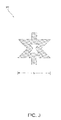
FIG. 3 illustrates a unit cell for a material having a negative coefficient of thermal expansion in accordance with various embodiments; -
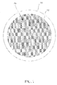
FIG. 4 illustrates a lattice of a material having a negative coefficient of thermal expansion in accordance with various embodiments; -
FIG. 5 illustrates a schematic view of a cooling air supply line in accordance with various embodiments; -
FIG. 6 illustrates a cross-section view of a metering coupon in accordance with various embodiments; -
FIG. 7 illustrates a cross-section view of a metering coupon which spans an entire cooling air supply line in accordance with various embodiments; and -
FIG. 8 illustrates a close-up view of a film hole in accordance with various embodiments. - The detailed description of various embodiments herein makes reference to the accompanying drawings, which show various embodiments by way of illustration. While these various embodiments are described in sufficient detail to enable those skilled in the art to practice the disclosure, it should be understood that other embodiments may be realized and that logical, chemical, and mechanical changes may be made without departing from the scope of the disclosure. Thus, the detailed description herein is presented for purposes of illustration only and not of limitation. For example, the steps recited in any of the method or process descriptions may be executed in any order and are not necessarily limited to the order presented. Furthermore, any reference to singular includes plural embodiments, and any reference to more than one component or step may include a singular embodiment or step. Also, any reference to attached, fixed, connected, or the like may include permanent, removable, temporary, partial, full, and/or any other possible attachment option. Additionally, any reference to without contact (or similar phrases) may also include reduced contact or minimal contact.
- Referring to
FIG. 1 , a gas turbine engine 100 (such as a turbofan gas turbine engine) is illustrated according to various embodiments.Gas turbine engine 100 is disposed aboutaxial centerline axis 120, which may also be referred to as axis ofrotation 120.Gas turbine engine 100 may comprise afan 140,compressor sections combustion section 180, andturbine sections compressor sections combustion section 180 and expanded across theturbine sections turbine sections high pressure rotors 192 andlow pressure rotors 194, which rotate in response to the expansion. Theturbine sections blades 196 and static airfoils orvanes 198. Cooling air may be supplied to theturbine sections compressor sections bearings 115 may support spools in thegas turbine engine 100.FIG. 1 provides a general understanding of the sections in a gas turbine engine, and is not intended to limit the disclosure. The present disclosure may extend to all types of turbine engines, including turbofan gas turbine engines and turbojet engines, for all types of applications. - The forward-aft positions of
gas turbine engine 100 lie along axis ofrotation 120. For example,fan 140 may be referred to as forward ofturbine section 190 andturbine section 190 may be referred to as aft offan 140. Typically, during operation ofgas turbine engine 100, air flows from forward to aft, for example, fromfan 140 toturbine section 190. As air flows fromfan 140 to the more aft components ofgas turbine engine 100, axis ofrotation 120 may also generally define the direction of the air stream flow. - Referring to
FIG. 2 , a perspective view of aturbine vane 200 is illustrated according to various embodiments. Theturbine vane 200 may comprise a plurality of film holes 210. Cooling air may be directed through the interior of theturbine vane 200 and out the film holes 210. The cooling air may form a thin protective layer around theturbine vane 200 which protects theturbine vane 200 from extreme high temperatures. - The temperatures experienced by the
turbine vane 200 and other engine components may be highest during takeoff, and may decrease during steady flight at cruise altitude. At the highest temperatures, more cooling air may be desirable to protect theturbine vane 200. However, theturbine vane 200 may expand with increasing temperatures due to the coefficient of thermal expansion of the material of theturbine vane 200. As theturbine vane 200 expands, an area of the film holes 210 may decrease. The decreasing area of the film holes 210 may result in less cooling air flowing through the film holes 210, decreasing the effectiveness of the protective layer of cooling air around theturbine vane 200. - In some cases, the supply of cooling air may be actively managed in order to increase the flow rate of cooling air or pressure of cooling air during high temperature periods. However, it may be desirable to passively manage the supply of cooling air. A material having a negative coefficient of thermal expansion may be utilized in order to passively manage the cooling air, such that the supply of cooling air does not need to be affected.
- Referring to
FIG. 3 , aunit cell 300 for a material having a negative coefficient of thermal expansion is illustrated according to various embodiments. In various embodiments, the material may comprise nickel, a nickel alloy, molysilicide nickel aluminide, zirconium tungstate, or any other suitable material. In various embodiments, the material may be fabricated using additive manufacturing. The material may be fabricated using selective laser sintering or direct metal laser sintering, in which a laser fuses powdered metal into a solid part. Theunit cell 300 shown inFIG. 3 is merely one example of a unit cell that may be used to form a material having a negative coefficient of thermal expansion, and those skilled in the art will appreciate that many different shapes may be used. In various embodiments,unit cell 300 may have a width W of less than 1 cm (0.4 inches), less than 1 mm (0.04 inches), or less than 100 microns (.004 inches). However, in various embodiments, width W may be any suitable size. - Referring to
FIG. 4 , alattice 400 of a material having a negative coefficient of thermal expansion is illustrated according to various embodiments. Theunit cell 300 fromFIG. 3 may be formed in a repetitive pattern. The pattern may cause thelattice 400 to contract as a temperature of the material increases. As the temperature increases, a cross-sectional area ofpores 410 betweenunit cells 300 may increase, allowing for increased air flow through thepores 410. - Referring to
FIG. 5 , a schematic view of a coolingair supply line 510 to acomponent 520 is illustrated according to various embodiments. Thecomponent 520 may comprise any component in a gas turbine engine which utilizes cooling air, such as a turbine vane, a turbine blade, a blade outer air seal, or a combustor panel. The coolingair supply line 510 may comprise ametering coupon 512. Themetering coupon 512 may comprise a material having a negative coefficient of thermal expansion. In response to a temperature of themetering coupon 512 increasing, the cross-sectional area of themetering coupon 512 may decrease, allowing a greater volume of cooling air per unit time to be supplied to thecomponent 520. - Referring to
FIG. 6 , a cross-section view of ametering coupon 612 is illustrated according to various embodiments. Themetering coupon 612 may be located within a coolingair supply line 620. Themetering coupon 612 may comprise anaperture 610 having a diameter D1. Cooling air may flow through theaperture 610. In response to themetering coupon 612 increasing in temperature, themetering coupon 612 may contract, and the diameter D1 of theaperture 610 may increase. Thus, in periods of relatively higher temperatures, themetering coupon 612 may allow more cooling air to flow through themetering coupon 612 in order to cool a component. - Referring to
FIG. 7 , a cross-section view of ametering coupon 712 which spans the entire coolingair supply line 720 is illustrated according to various embodiments. Themetering coupon 712 may comprise a plurality ofpores 730. In various embodiments, themetering coupon 712 may comprise a cross-section as described with reference toFIG. 4 . As the temperature of themetering coupon 712 increases, the cross-sectional area of thepores 730 may increase, allowing more cooling air to flow through themetering coupon 712. - Referring to
FIG. 8 , a close-up view of afilm hole 810 is illustrated according to various embodiments.Film hole 810 may be in a gasturbine engine component 800. The gasturbine engine component 800 may be any component in a gas turbine engine which utilizes film holes, such as a turbine vane, turbine blade, blade outer air seal, or combustor panel.Film hole 810 may comprise ametering coupon 820 comprising a material having a negative coefficient of thermal expansion. Themetering coupon 820 may comprise anaperture 830 having a diameter D2. In response to an increase in temperature of theturbine component 800, themetering coupon 820 may contract, and the diameter D2 may increase, allowing for additional cooling air to flow through theaperture 830 to protect the gasturbine engine component 800. In various embodiments, themetering coupon 820 may be coated onto thefilm hole 810. In various embodiments,metering coupon 820 may span the entire cross-section of thefilm hole 810. - The specific materials, configurations, and locations of materials having a negative coefficient of thermal expansion disclosed herein are merely examples of the present disclosure. Those skilled in the art will recognize that materials having a negative coefficient of thermal expansion may be utilized in a variety of configurations in order to passively manage the supply of cooling air within a gas turbine engine.
- Benefits, other advantages, and solutions to problems have been described herein with regard to specific embodiments. Furthermore, the connecting lines shown in the various figures contained herein are intended to represent exemplary functional relationships and/or physical couplings between the various elements. It should be noted that many alternative or additional functional relationships or physical connections may be present in a practical system. However, the benefits, advantages, solutions to problems, and any elements that may cause any benefit, advantage, or solution to occur or become more pronounced are not to be construed as critical, required, or essential features or elements of the disclosure. The scope of the disclosure is accordingly to be limited by nothing other than the appended claims, in which reference to an element in the singular is not intended to mean "one and only one" unless explicitly so stated, but rather "one or more." Moreover, where a phrase similar to "at least one of A, B, or C" is used in the claims, it is intended that the phrase be interpreted to mean that A alone may be present in an embodiment, B alone may be present in an embodiment, C alone may be present in an embodiment, or that any combination of the elements A, B and C may be present in a single embodiment; for example, A and B, A and C, B and C, or A and B and C. Different cross-hatching is used throughout the figures to denote different parts but not necessarily to denote the same or different materials.
- Systems, methods and apparatus are provided herein. In the detailed description herein, references to "one embodiment", "an embodiment", "various embodiments", etc., indicate that the embodiment described may include a particular feature, structure, or characteristic, but every embodiment may not necessarily include the particular feature, structure, or characteristic. Moreover, such phrases are not necessarily referring to the same embodiment. Further, when a particular feature, structure, or characteristic is described in connection with an embodiment, it is submitted that it is within the knowledge of one skilled in the art to affect such feature, structure, or characteristic in connection with other embodiments whether or not explicitly described. After reading the description, it will be apparent to one skilled in the relevant art(s) how to implement the disclosure in alternative embodiments.
- Furthermore, no element, component, or method step in the present disclosure is intended to be dedicated to the public regardless of whether the element, component, or method step is explicitly recited in the claims. No claim element herein is to be construed under the provisions of 35 U.S.C. 112(f) unless the element is expressly recited using the phrase "means for." As used herein, the terms "comprises", "comprising", or any other variation thereof, are intended to cover a non-exclusive inclusion, such that a process, method, article, or apparatus that comprises a list of elements does not include only those elements but may include other elements not expressly listed or inherent to such process, method, article, or apparatus.
Claims (14)
- A cooling system in a gas turbine engine (100) comprising:a component (520; 800) in the gas turbine engine (100);a cooling air supply line (510; 620; 720) configured to supply cooling air to the component (520; 800); anda metering coupon (512; 612; 712; 820) having a negative coefficient of thermal expansion.
- The cooling system of claim 1, wherein the metering coupon (512; 612; 712; 820) is located within the cooling air supply line (510).
- The cooling system of claim 1, wherein the metering coupon (512; 612; 712; 820) is located within a film hole (810) in the component (520; 800).
- The cooling system of claim 1 or 2, wherein the metering coupon (512; 612; 712; 820) spans an entire cross-section of the cooling air supply line (510; 620; 720).
- The cooling system of claim 1 or 3, wherein the metering coupon (512; 612; 712; 820) is coated on a film hole (810) in the component (520; 800).
- The cooling system of any preceding claim, wherein the metering coupon (512; 612; 712; 820) is configured to passively manage cooling air supplied to the component (520; 800).
- A gas turbine engine comprising:the cooling system of any preceding claim, wherein the cooling air supply line (510; 620; 720) is in fluid communication with the component (520; 800); andwherein the metering coupon (512; 612; 712; 820) is in fluid communication with the cooling air supply line (510; 620; 720), and wherein the metering coupon (512; 612; 712; 820) is configured to passively manage cooling air from the cooling air supply line (510; 620; 720).
- The gas turbine engine of claim 7, wherein the metering coupon (512; 612; 712; 820) is configured to increase airflow in response to an increase in temperature.
- A gas turbine engine component (520; 800) comprising:a film hole (810); anda material having a negative coefficient of thermal expansion located within the film hole (810).
- The gas turbine engine component of claim 9, wherein the material is configured to passively manage cooling air flowing through the film hole (810).
- The gas turbine engine component of claim 9 or 10, wherein the material is coated on the film hole (810).
- The gas turbine engine component of claim 9, 10 or 11, wherein the material spans an entire cross-section of the film hole (810).
- The cooling system, gas turbine engine or gas turbine engine component of any preceding claim, wherein the component (520; 800) comprises at least one of a vane, a turbine vane (198), a blade, a turbine blade, a blade outer air seal, or a combustor panel.
- The cooling system, gas turbine engine or gas turbine engine component of any preceding claim, wherein the metering coupon (512; 612; 712; 820) or material comprises at least one of nickel or zirconium tungstate.
Priority Applications (1)
| Application Number | Priority Date | Filing Date | Title |
|---|---|---|---|
| EP19201550.1A EP3608507B1 (en) | 2014-09-24 | 2015-07-21 | Self-modulated cooling on turbine components |
Applications Claiming Priority (1)
| Application Number | Priority Date | Filing Date | Title |
|---|---|---|---|
| US201462054734P | 2014-09-24 | 2014-09-24 |
Related Child Applications (2)
| Application Number | Title | Priority Date | Filing Date |
|---|---|---|---|
| EP19201550.1A Division EP3608507B1 (en) | 2014-09-24 | 2015-07-21 | Self-modulated cooling on turbine components |
| EP19201550.1A Division-Into EP3608507B1 (en) | 2014-09-24 | 2015-07-21 | Self-modulated cooling on turbine components |
Publications (2)
| Publication Number | Publication Date |
|---|---|
| EP3000973A1 true EP3000973A1 (en) | 2016-03-30 |
| EP3000973B1 EP3000973B1 (en) | 2019-11-13 |
Family
ID=54007481
Family Applications (2)
| Application Number | Title | Priority Date | Filing Date |
|---|---|---|---|
| EP19201550.1A Active EP3608507B1 (en) | 2014-09-24 | 2015-07-21 | Self-modulated cooling on turbine components |
| EP15177726.5A Active EP3000973B1 (en) | 2014-09-24 | 2015-07-21 | Self-modulated cooling on turbine components |
Family Applications Before (1)
| Application Number | Title | Priority Date | Filing Date |
|---|---|---|---|
| EP19201550.1A Active EP3608507B1 (en) | 2014-09-24 | 2015-07-21 | Self-modulated cooling on turbine components |
Country Status (2)
| Country | Link |
|---|---|
| US (1) | US9845731B2 (en) |
| EP (2) | EP3608507B1 (en) |
Cited By (1)
| Publication number | Priority date | Publication date | Assignee | Title |
|---|---|---|---|---|
| EP3816408A1 (en) * | 2019-11-04 | 2021-05-05 | Raytheon Technologies Corporation | Negative thermal expansion compressor case for improved tip clearance |
Families Citing this family (10)
| Publication number | Priority date | Publication date | Assignee | Title |
|---|---|---|---|---|
| EP2910765B1 (en) * | 2014-02-21 | 2017-10-25 | Rolls-Royce Corporation | Single phase micro/mini channel heat exchangers for gas turbine intercooling and corresponding method |
| EP2910887B1 (en) | 2014-02-21 | 2019-06-26 | Rolls-Royce Corporation | Microchannel heat exchangers for gas turbine intercooling and condensing as well as corresponding method |
| GB201700914D0 (en) * | 2017-01-19 | 2017-03-08 | Rolls Royce Plc | A sealing element and a method of maufacturing the same |
| FR3065059B1 (en) * | 2017-04-11 | 2020-11-06 | Office National Detudes Rech Aerospatiales | SELF-ADAPTIVE VARIABLE GEOMETRY GAS TURBINE FIREPLACE |
| US10502093B2 (en) * | 2017-12-13 | 2019-12-10 | Pratt & Whitney Canada Corp. | Turbine shroud cooling |
| US10844728B2 (en) | 2019-04-17 | 2020-11-24 | General Electric Company | Turbine engine airfoil with a trailing edge |
| US12338738B2 (en) | 2022-07-05 | 2025-06-24 | General Electric Company | Variable flowpath casings for blade tip clearance control |
| US12012859B2 (en) | 2022-07-11 | 2024-06-18 | General Electric Company | Variable flowpath casings for blade tip clearance control |
| US11808157B1 (en) | 2022-07-13 | 2023-11-07 | General Electric Company | Variable flowpath casings for blade tip clearance control |
| US12025011B2 (en) | 2022-11-17 | 2024-07-02 | General Electric Company | Blade tip clearance control using material with negative thermal expansion coefficients |
Citations (5)
| Publication number | Priority date | Publication date | Assignee | Title |
|---|---|---|---|---|
| EP1584789A1 (en) * | 2004-04-08 | 2005-10-12 | Siemens Aktiengesellschaft | Coolable airfoil |
| US20070036942A1 (en) * | 2005-08-11 | 2007-02-15 | Rolls-Royce Plc | Cooling method and apparatus |
| EP1936468A1 (en) * | 2006-12-22 | 2008-06-25 | Siemens Aktiengesellschaft | Bi-metallic elements for adjusting a cooling channel |
| EP2423346A1 (en) * | 2010-08-30 | 2012-02-29 | United Technologies Corporation | Minimizing Blockage of Holes in Turbine Engine Components |
| EP2716867A1 (en) * | 2012-10-05 | 2014-04-09 | General Electric Company | Turbine components with adaptive cooling pathways |
Family Cites Families (10)
| Publication number | Priority date | Publication date | Assignee | Title |
|---|---|---|---|---|
| US5514360A (en) * | 1995-03-01 | 1996-05-07 | The State Of Oregon, Acting By And Through The Oregon State Board Of Higher Education, Acting For And On Behalf Of Oregon State University | Negative thermal expansion materials |
| US5919720A (en) | 1997-04-15 | 1999-07-06 | State Of Oregon Acting By And Through The State Board Of Higher Education On Behalf Of Oregon State University | Materials with low or negative thermal expansion |
| GB2354290B (en) * | 1999-09-18 | 2004-02-25 | Rolls Royce Plc | A cooling air flow control device for a gas turbine engine |
| US7241107B2 (en) * | 2005-05-19 | 2007-07-10 | Spanks Jr William A | Gas turbine airfoil with adjustable cooling air flow passages |
| US7441599B2 (en) | 2005-11-18 | 2008-10-28 | Chevron U.S.A. Inc. | Controlling the pressure within an annular volume of a wellbore |
| JP4125765B2 (en) * | 2006-09-28 | 2008-07-30 | 日本パーカライジング株式会社 | Method of coating ceramic film of metal, electrolytic solution used therefor, ceramic film and metal material |
| US20090226327A1 (en) * | 2008-03-07 | 2009-09-10 | Siemens Power Generation, Inc. | Gas Turbine Engine Including Temperature Control Device and Method Using Memory Metal |
| US8142874B1 (en) * | 2009-02-26 | 2012-03-27 | United States Of America As Represented By The Secretary Of The Air Force | Bi-material composite structure with reduced thermal expansion |
| US8871338B2 (en) * | 2011-09-07 | 2014-10-28 | Lawrence Livermore National Security, Llc | Lattice-structures and constructs with designed thermal expansion coefficients |
| EP3068974B1 (en) * | 2013-11-14 | 2020-04-01 | General Electric Company | Turbine components with negative cte features |
-
2015
- 2015-06-24 US US14/749,438 patent/US9845731B2/en active Active
- 2015-07-21 EP EP19201550.1A patent/EP3608507B1/en active Active
- 2015-07-21 EP EP15177726.5A patent/EP3000973B1/en active Active
Patent Citations (5)
| Publication number | Priority date | Publication date | Assignee | Title |
|---|---|---|---|---|
| EP1584789A1 (en) * | 2004-04-08 | 2005-10-12 | Siemens Aktiengesellschaft | Coolable airfoil |
| US20070036942A1 (en) * | 2005-08-11 | 2007-02-15 | Rolls-Royce Plc | Cooling method and apparatus |
| EP1936468A1 (en) * | 2006-12-22 | 2008-06-25 | Siemens Aktiengesellschaft | Bi-metallic elements for adjusting a cooling channel |
| EP2423346A1 (en) * | 2010-08-30 | 2012-02-29 | United Technologies Corporation | Minimizing Blockage of Holes in Turbine Engine Components |
| EP2716867A1 (en) * | 2012-10-05 | 2014-04-09 | General Electric Company | Turbine components with adaptive cooling pathways |
Cited By (2)
| Publication number | Priority date | Publication date | Assignee | Title |
|---|---|---|---|---|
| EP3816408A1 (en) * | 2019-11-04 | 2021-05-05 | Raytheon Technologies Corporation | Negative thermal expansion compressor case for improved tip clearance |
| US11255214B2 (en) | 2019-11-04 | 2022-02-22 | Raytheon Technologies Corporation | Negative thermal expansion compressor case for improved tip clearance |
Also Published As
| Publication number | Publication date |
|---|---|
| US20160084167A1 (en) | 2016-03-24 |
| EP3608507B1 (en) | 2021-03-31 |
| EP3000973B1 (en) | 2019-11-13 |
| US9845731B2 (en) | 2017-12-19 |
| EP3608507A1 (en) | 2020-02-12 |
Similar Documents
| Publication | Publication Date | Title |
|---|---|---|
| EP3000973B1 (en) | Self-modulated cooling on turbine components | |
| US10364706B2 (en) | Meter plate for blade outer air seal | |
| EP2994618B1 (en) | Anti-ice splitter nose | |
| US10082039B2 (en) | Segmented annular seal | |
| US20170022842A1 (en) | Gas turbine engines including channel-cooled hooks for retaining a part relative to an engine casing structure | |
| US9957894B2 (en) | Outer diameter platform cooling hole system and assembly | |
| EP2951398B1 (en) | Gas turbine engine comprising a double snapped cover plate for rotor disk | |
| JP2004176723A (en) | Turbine airfoil row with long and short chord length and high and low high temperature performance | |
| US9957810B2 (en) | Film hole with protruding flow accumulator | |
| EP3246534B1 (en) | Heat shield with axial retention | |
| EP3306056A1 (en) | Flange heat shield | |
| US11041396B2 (en) | Axial-radial cooling slots on inner air seal | |
| EP3620617B1 (en) | Core case heating for gas turbine engines | |
| US20170234447A1 (en) | Methods and systems for modulating airflow | |
| EP3617458A1 (en) | Axially preloaded seal | |
| EP3026217B1 (en) | Turbine rotor or stator segmented sideplates with anti-rotation | |
| US10415474B2 (en) | Method and system for phase change material component cooling | |
| US10132168B2 (en) | Airfoil | |
| US20160237850A1 (en) | Systems and methods for vane cooling | |
| EP3101229B1 (en) | Impingement cooling insert | |
| EP3656983B1 (en) | Turbine vane assembly | |
| US20260036054A1 (en) | Turbine blade for a gas turbine engine |
Legal Events
| Date | Code | Title | Description |
|---|---|---|---|
| PUAI | Public reference made under article 153(3) epc to a published international application that has entered the european phase |
Free format text: ORIGINAL CODE: 0009012 |
|
| AK | Designated contracting states |
Kind code of ref document: A1 Designated state(s): AL AT BE BG CH CY CZ DE DK EE ES FI FR GB GR HR HU IE IS IT LI LT LU LV MC MK MT NL NO PL PT RO RS SE SI SK SM TR |
|
| AX | Request for extension of the european patent |
Extension state: BA ME |
|
| RAP1 | Party data changed (applicant data changed or rights of an application transferred) |
Owner name: UNITED TECHNOLOGIES CORPORATION |
|
| 17P | Request for examination filed |
Effective date: 20160928 |
|
| RBV | Designated contracting states (corrected) |
Designated state(s): AL AT BE BG CH CY CZ DE DK EE ES FI FR GB GR HR HU IE IS IT LI LT LU LV MC MK MT NL NO PL PT RO RS SE SI SK SM TR |
|
| RIC1 | Information provided on ipc code assigned before grant |
Ipc: F23R 3/06 20060101ALI20190411BHEP Ipc: F01D 25/12 20060101ALI20190411BHEP Ipc: F01D 5/18 20060101AFI20190411BHEP Ipc: F01D 11/24 20060101ALI20190411BHEP Ipc: G05D 25/02 20060101ALI20190411BHEP Ipc: F02C 7/25 20060101ALI20190411BHEP Ipc: F01D 9/04 20060101ALI20190411BHEP Ipc: F02C 7/18 20060101ALI20190411BHEP Ipc: F23R 3/26 20060101ALI20190411BHEP Ipc: F02C 7/20 20060101ALI20190411BHEP Ipc: G05D 23/02 20060101ALI20190411BHEP Ipc: F01D 11/14 20060101ALI20190411BHEP Ipc: F23R 3/00 20060101ALI20190411BHEP Ipc: F01D 11/08 20060101ALI20190411BHEP |
|
| GRAP | Despatch of communication of intention to grant a patent |
Free format text: ORIGINAL CODE: EPIDOSNIGR1 |
|
| STAA | Information on the status of an ep patent application or granted ep patent |
Free format text: STATUS: GRANT OF PATENT IS INTENDED |
|
| INTG | Intention to grant announced |
Effective date: 20190531 |
|
| GRAS | Grant fee paid |
Free format text: ORIGINAL CODE: EPIDOSNIGR3 |
|
| GRAA | (expected) grant |
Free format text: ORIGINAL CODE: 0009210 |
|
| STAA | Information on the status of an ep patent application or granted ep patent |
Free format text: STATUS: THE PATENT HAS BEEN GRANTED |
|
| AK | Designated contracting states |
Kind code of ref document: B1 Designated state(s): AL AT BE BG CH CY CZ DE DK EE ES FI FR GB GR HR HU IE IS IT LI LT LU LV MC MK MT NL NO PL PT RO RS SE SI SK SM TR |
|
| REG | Reference to a national code |
Ref country code: CH Ref legal event code: EP Ref country code: AT Ref legal event code: REF Ref document number: 1201840 Country of ref document: AT Kind code of ref document: T Effective date: 20191115 |
|
| REG | Reference to a national code |
Ref country code: DE Ref legal event code: R096 Ref document number: 602015041512 Country of ref document: DE |
|
| REG | Reference to a national code |
Ref country code: IE Ref legal event code: FG4D |
|
| REG | Reference to a national code |
Ref country code: NL Ref legal event code: MP Effective date: 20191113 |
|
| REG | Reference to a national code |
Ref country code: LT Ref legal event code: MG4D |
|
| PG25 | Lapsed in a contracting state [announced via postgrant information from national office to epo] |
Ref country code: BG Free format text: LAPSE BECAUSE OF FAILURE TO SUBMIT A TRANSLATION OF THE DESCRIPTION OR TO PAY THE FEE WITHIN THE PRESCRIBED TIME-LIMIT Effective date: 20200213 Ref country code: FI Free format text: LAPSE BECAUSE OF FAILURE TO SUBMIT A TRANSLATION OF THE DESCRIPTION OR TO PAY THE FEE WITHIN THE PRESCRIBED TIME-LIMIT Effective date: 20191113 Ref country code: SE Free format text: LAPSE BECAUSE OF FAILURE TO SUBMIT A TRANSLATION OF THE DESCRIPTION OR TO PAY THE FEE WITHIN THE PRESCRIBED TIME-LIMIT Effective date: 20191113 Ref country code: LV Free format text: LAPSE BECAUSE OF FAILURE TO SUBMIT A TRANSLATION OF THE DESCRIPTION OR TO PAY THE FEE WITHIN THE PRESCRIBED TIME-LIMIT Effective date: 20191113 Ref country code: NL Free format text: LAPSE BECAUSE OF FAILURE TO SUBMIT A TRANSLATION OF THE DESCRIPTION OR TO PAY THE FEE WITHIN THE PRESCRIBED TIME-LIMIT Effective date: 20191113 Ref country code: LT Free format text: LAPSE BECAUSE OF FAILURE TO SUBMIT A TRANSLATION OF THE DESCRIPTION OR TO PAY THE FEE WITHIN THE PRESCRIBED TIME-LIMIT Effective date: 20191113 Ref country code: PL Free format text: LAPSE BECAUSE OF FAILURE TO SUBMIT A TRANSLATION OF THE DESCRIPTION OR TO PAY THE FEE WITHIN THE PRESCRIBED TIME-LIMIT Effective date: 20191113 Ref country code: GR Free format text: LAPSE BECAUSE OF FAILURE TO SUBMIT A TRANSLATION OF THE DESCRIPTION OR TO PAY THE FEE WITHIN THE PRESCRIBED TIME-LIMIT Effective date: 20200214 Ref country code: NO Free format text: LAPSE BECAUSE OF FAILURE TO SUBMIT A TRANSLATION OF THE DESCRIPTION OR TO PAY THE FEE WITHIN THE PRESCRIBED TIME-LIMIT Effective date: 20200213 Ref country code: PT Free format text: LAPSE BECAUSE OF FAILURE TO SUBMIT A TRANSLATION OF THE DESCRIPTION OR TO PAY THE FEE WITHIN THE PRESCRIBED TIME-LIMIT Effective date: 20200313 |
|
| PG25 | Lapsed in a contracting state [announced via postgrant information from national office to epo] |
Ref country code: IS Free format text: LAPSE BECAUSE OF FAILURE TO SUBMIT A TRANSLATION OF THE DESCRIPTION OR TO PAY THE FEE WITHIN THE PRESCRIBED TIME-LIMIT Effective date: 20200313 Ref country code: RS Free format text: LAPSE BECAUSE OF FAILURE TO SUBMIT A TRANSLATION OF THE DESCRIPTION OR TO PAY THE FEE WITHIN THE PRESCRIBED TIME-LIMIT Effective date: 20191113 Ref country code: HR Free format text: LAPSE BECAUSE OF FAILURE TO SUBMIT A TRANSLATION OF THE DESCRIPTION OR TO PAY THE FEE WITHIN THE PRESCRIBED TIME-LIMIT Effective date: 20191113 |
|
| PG25 | Lapsed in a contracting state [announced via postgrant information from national office to epo] |
Ref country code: AL Free format text: LAPSE BECAUSE OF FAILURE TO SUBMIT A TRANSLATION OF THE DESCRIPTION OR TO PAY THE FEE WITHIN THE PRESCRIBED TIME-LIMIT Effective date: 20191113 |
|
| PG25 | Lapsed in a contracting state [announced via postgrant information from national office to epo] |
Ref country code: DK Free format text: LAPSE BECAUSE OF FAILURE TO SUBMIT A TRANSLATION OF THE DESCRIPTION OR TO PAY THE FEE WITHIN THE PRESCRIBED TIME-LIMIT Effective date: 20191113 Ref country code: ES Free format text: LAPSE BECAUSE OF FAILURE TO SUBMIT A TRANSLATION OF THE DESCRIPTION OR TO PAY THE FEE WITHIN THE PRESCRIBED TIME-LIMIT Effective date: 20191113 Ref country code: CZ Free format text: LAPSE BECAUSE OF FAILURE TO SUBMIT A TRANSLATION OF THE DESCRIPTION OR TO PAY THE FEE WITHIN THE PRESCRIBED TIME-LIMIT Effective date: 20191113 Ref country code: RO Free format text: LAPSE BECAUSE OF FAILURE TO SUBMIT A TRANSLATION OF THE DESCRIPTION OR TO PAY THE FEE WITHIN THE PRESCRIBED TIME-LIMIT Effective date: 20191113 Ref country code: EE Free format text: LAPSE BECAUSE OF FAILURE TO SUBMIT A TRANSLATION OF THE DESCRIPTION OR TO PAY THE FEE WITHIN THE PRESCRIBED TIME-LIMIT Effective date: 20191113 |
|
| REG | Reference to a national code |
Ref country code: DE Ref legal event code: R097 Ref document number: 602015041512 Country of ref document: DE |
|
| REG | Reference to a national code |
Ref country code: AT Ref legal event code: MK05 Ref document number: 1201840 Country of ref document: AT Kind code of ref document: T Effective date: 20191113 |
|
| PG25 | Lapsed in a contracting state [announced via postgrant information from national office to epo] |
Ref country code: SK Free format text: LAPSE BECAUSE OF FAILURE TO SUBMIT A TRANSLATION OF THE DESCRIPTION OR TO PAY THE FEE WITHIN THE PRESCRIBED TIME-LIMIT Effective date: 20191113 Ref country code: SM Free format text: LAPSE BECAUSE OF FAILURE TO SUBMIT A TRANSLATION OF THE DESCRIPTION OR TO PAY THE FEE WITHIN THE PRESCRIBED TIME-LIMIT Effective date: 20191113 |
|
| PLBE | No opposition filed within time limit |
Free format text: ORIGINAL CODE: 0009261 |
|
| STAA | Information on the status of an ep patent application or granted ep patent |
Free format text: STATUS: NO OPPOSITION FILED WITHIN TIME LIMIT |
|
| 26N | No opposition filed |
Effective date: 20200814 |
|
| PG25 | Lapsed in a contracting state [announced via postgrant information from national office to epo] |
Ref country code: AT Free format text: LAPSE BECAUSE OF FAILURE TO SUBMIT A TRANSLATION OF THE DESCRIPTION OR TO PAY THE FEE WITHIN THE PRESCRIBED TIME-LIMIT Effective date: 20191113 Ref country code: SI Free format text: LAPSE BECAUSE OF FAILURE TO SUBMIT A TRANSLATION OF THE DESCRIPTION OR TO PAY THE FEE WITHIN THE PRESCRIBED TIME-LIMIT Effective date: 20191113 |
|
| PG25 | Lapsed in a contracting state [announced via postgrant information from national office to epo] |
Ref country code: IT Free format text: LAPSE BECAUSE OF FAILURE TO SUBMIT A TRANSLATION OF THE DESCRIPTION OR TO PAY THE FEE WITHIN THE PRESCRIBED TIME-LIMIT Effective date: 20191113 |
|
| PG25 | Lapsed in a contracting state [announced via postgrant information from national office to epo] |
Ref country code: MC Free format text: LAPSE BECAUSE OF FAILURE TO SUBMIT A TRANSLATION OF THE DESCRIPTION OR TO PAY THE FEE WITHIN THE PRESCRIBED TIME-LIMIT Effective date: 20191113 |
|
| REG | Reference to a national code |
Ref country code: CH Ref legal event code: PL |
|
| REG | Reference to a national code |
Ref country code: BE Ref legal event code: MM Effective date: 20200731 |
|
| PG25 | Lapsed in a contracting state [announced via postgrant information from national office to epo] |
Ref country code: CH Free format text: LAPSE BECAUSE OF NON-PAYMENT OF DUE FEES Effective date: 20200731 Ref country code: LU Free format text: LAPSE BECAUSE OF NON-PAYMENT OF DUE FEES Effective date: 20200721 Ref country code: LI Free format text: LAPSE BECAUSE OF NON-PAYMENT OF DUE FEES Effective date: 20200731 |
|
| PG25 | Lapsed in a contracting state [announced via postgrant information from national office to epo] |
Ref country code: BE Free format text: LAPSE BECAUSE OF NON-PAYMENT OF DUE FEES Effective date: 20200731 |
|
| PG25 | Lapsed in a contracting state [announced via postgrant information from national office to epo] |
Ref country code: IE Free format text: LAPSE BECAUSE OF NON-PAYMENT OF DUE FEES Effective date: 20200721 |
|
| PG25 | Lapsed in a contracting state [announced via postgrant information from national office to epo] |
Ref country code: TR Free format text: LAPSE BECAUSE OF FAILURE TO SUBMIT A TRANSLATION OF THE DESCRIPTION OR TO PAY THE FEE WITHIN THE PRESCRIBED TIME-LIMIT Effective date: 20191113 Ref country code: MT Free format text: LAPSE BECAUSE OF FAILURE TO SUBMIT A TRANSLATION OF THE DESCRIPTION OR TO PAY THE FEE WITHIN THE PRESCRIBED TIME-LIMIT Effective date: 20191113 Ref country code: CY Free format text: LAPSE BECAUSE OF FAILURE TO SUBMIT A TRANSLATION OF THE DESCRIPTION OR TO PAY THE FEE WITHIN THE PRESCRIBED TIME-LIMIT Effective date: 20191113 |
|
| PG25 | Lapsed in a contracting state [announced via postgrant information from national office to epo] |
Ref country code: MK Free format text: LAPSE BECAUSE OF FAILURE TO SUBMIT A TRANSLATION OF THE DESCRIPTION OR TO PAY THE FEE WITHIN THE PRESCRIBED TIME-LIMIT Effective date: 20191113 |
|
| REG | Reference to a national code |
Ref country code: DE Ref legal event code: R081 Ref document number: 602015041512 Country of ref document: DE Owner name: RAYTHEON TECHNOLOGIES CORPORATION (N.D.GES.D.S, US Free format text: FORMER OWNER: UNITED TECHNOLOGIES CORPORATION, FARMINGTON, CONN., US Ref country code: DE Ref legal event code: R081 Ref document number: 602015041512 Country of ref document: DE Owner name: RTX CORPORATION (N.D.GES.D. STAATES DELAWARE),, US Free format text: FORMER OWNER: UNITED TECHNOLOGIES CORPORATION, FARMINGTON, CONN., US |
|
| P01 | Opt-out of the competence of the unified patent court (upc) registered |
Effective date: 20230520 |
|
| PGFP | Annual fee paid to national office [announced via postgrant information from national office to epo] |
Ref country code: GB Payment date: 20250619 Year of fee payment: 11 |
|
| PGFP | Annual fee paid to national office [announced via postgrant information from national office to epo] |
Ref country code: FR Payment date: 20250620 Year of fee payment: 11 |
|
| PGFP | Annual fee paid to national office [announced via postgrant information from national office to epo] |
Ref country code: DE Payment date: 20250620 Year of fee payment: 11 |
|
| REG | Reference to a national code |
Ref country code: DE Ref legal event code: R081 Ref document number: 602015041512 Country of ref document: DE Owner name: RTX CORPORATION (N.D.GES.D. STAATES DELAWARE),, US Free format text: FORMER OWNER: RAYTHEON TECHNOLOGIES CORPORATION (N.D.GES.D.STAATES DELAWARE), ARLINGTON, VA, US |