EP3000730B1 - Autorotative enhancement system - Google Patents
Autorotative enhancement system Download PDFInfo
- Publication number
- EP3000730B1 EP3000730B1 EP15194261.2A EP15194261A EP3000730B1 EP 3000730 B1 EP3000730 B1 EP 3000730B1 EP 15194261 A EP15194261 A EP 15194261A EP 3000730 B1 EP3000730 B1 EP 3000730B1
- Authority
- EP
- European Patent Office
- Prior art keywords
- generator
- motor
- energy
- transmission
- engine
- Prior art date
- Legal status (The legal status is an assumption and is not a legal conclusion. Google has not performed a legal analysis and makes no representation as to the accuracy of the status listed.)
- Active
Links
Images


Classifications
-
- B—PERFORMING OPERATIONS; TRANSPORTING
- B64—AIRCRAFT; AVIATION; COSMONAUTICS
- B64C—AEROPLANES; HELICOPTERS
- B64C27/00—Rotorcraft; Rotors peculiar thereto
- B64C27/006—Safety devices
-
- B—PERFORMING OPERATIONS; TRANSPORTING
- B64—AIRCRAFT; AVIATION; COSMONAUTICS
- B64C—AEROPLANES; HELICOPTERS
- B64C27/00—Rotorcraft; Rotors peculiar thereto
- B64C27/04—Helicopters
- B64C27/12—Rotor drives
-
- B—PERFORMING OPERATIONS; TRANSPORTING
- B64—AIRCRAFT; AVIATION; COSMONAUTICS
- B64D—EQUIPMENT FOR FITTING IN OR TO AIRCRAFT; FLIGHT SUITS; PARACHUTES; ARRANGEMENT OR MOUNTING OF POWER PLANTS OR PROPULSION TRANSMISSIONS IN AIRCRAFT
- B64D27/00—Arrangement or mounting of power plants in aircraft; Aircraft characterised by the type or position of power plants
- B64D27/02—Aircraft characterised by the type or position of power plants
- B64D27/30—Aircraft characterised by electric power plants
- B64D27/33—Hybrid electric aircraft
-
- B—PERFORMING OPERATIONS; TRANSPORTING
- B64—AIRCRAFT; AVIATION; COSMONAUTICS
- B64D—EQUIPMENT FOR FITTING IN OR TO AIRCRAFT; FLIGHT SUITS; PARACHUTES; ARRANGEMENT OR MOUNTING OF POWER PLANTS OR PROPULSION TRANSMISSIONS IN AIRCRAFT
- B64D27/00—Arrangement or mounting of power plants in aircraft; Aircraft characterised by the type or position of power plants
- B64D27/02—Aircraft characterised by the type or position of power plants
- B64D27/30—Aircraft characterised by electric power plants
- B64D27/35—Arrangements for on-board electric energy production, distribution, recovery or storage
- B64D27/357—Arrangements for on-board electric energy production, distribution, recovery or storage using batteries
-
- B—PERFORMING OPERATIONS; TRANSPORTING
- B64—AIRCRAFT; AVIATION; COSMONAUTICS
- B64D—EQUIPMENT FOR FITTING IN OR TO AIRCRAFT; FLIGHT SUITS; PARACHUTES; ARRANGEMENT OR MOUNTING OF POWER PLANTS OR PROPULSION TRANSMISSIONS IN AIRCRAFT
- B64D27/00—Arrangement or mounting of power plants in aircraft; Aircraft characterised by the type or position of power plants
- B64D27/02—Aircraft characterised by the type or position of power plants
- B64D27/026—Aircraft characterised by the type or position of power plants comprising different types of power plants, e.g. combination of a piston engine and a gas-turbine
-
- Y—GENERAL TAGGING OF NEW TECHNOLOGICAL DEVELOPMENTS; GENERAL TAGGING OF CROSS-SECTIONAL TECHNOLOGIES SPANNING OVER SEVERAL SECTIONS OF THE IPC; TECHNICAL SUBJECTS COVERED BY FORMER USPC CROSS-REFERENCE ART COLLECTIONS [XRACs] AND DIGESTS
- Y02—TECHNOLOGIES OR APPLICATIONS FOR MITIGATION OR ADAPTATION AGAINST CLIMATE CHANGE
- Y02T—CLIMATE CHANGE MITIGATION TECHNOLOGIES RELATED TO TRANSPORTATION
- Y02T50/00—Aeronautics or air transport
- Y02T50/60—Efficient propulsion technologies, e.g. for aircraft
-
- Y—GENERAL TAGGING OF NEW TECHNOLOGICAL DEVELOPMENTS; GENERAL TAGGING OF CROSS-SECTIONAL TECHNOLOGIES SPANNING OVER SEVERAL SECTIONS OF THE IPC; TECHNICAL SUBJECTS COVERED BY FORMER USPC CROSS-REFERENCE ART COLLECTIONS [XRACs] AND DIGESTS
- Y10—TECHNICAL SUBJECTS COVERED BY FORMER USPC
- Y10T—TECHNICAL SUBJECTS COVERED BY FORMER US CLASSIFICATION
- Y10T29/00—Metal working
- Y10T29/49—Method of mechanical manufacture
- Y10T29/49002—Electrical device making
- Y10T29/49117—Conductor or circuit manufacturing
Definitions
- a helicopter may employ autorotation to execute a safe landing, wherein the main rotor system of the helicopter is turned by the action of air moving up through the rotor. This generates lift and drag to slow the descent of the helicopter. Autorotation may allow the helicopter to descend and land safely without the use of the main engine. Autorotation may be particularly useful for single engine helicopters.
- EP2327625 (A1 ) discloses an installation that has a tail gearbox (BTA) driving an anti-torque rotor of a helicopter.
- Electric motors i.e. brushless motors, are mechanically connected to a main gearbox (BTP) to drive the main gearbox and connected to the tail gearbox to drive the tail gearbox.
- An engine e.g. piston engine, is connected to the main gearbox by a shaft.
- the tail gearbox is connected via another shaft to the engine or to the main gearbox.
- Maximum electric power of the electric motor is equal to percentage of a product of nominal speed of rotation multiplied by torque limit.
- a method for driving a rotary wing and an anti-torque rotor of a helicopter is also disclosed.
- DE102008014404 (A1 ) discloses an aircraft that has a drive designed as a hybrid-drive.
- a shaft-power turbine drives a generator for generation of current that is fed to an electric motor and/or back-up batteries, where the electric motor functions as a primary drive.
- the current from the shaft-power turbine is rectified with a rectifier.
- the hybrid-drive is controlled in such a manner that the electric motor is operated with current from the back-up batteries during a case of failure of the shaft-power turbine.
- US2012025032 (A1 ) discloses a hybrid power plant for an aircraft which comprises at least: a hybrid drive system having a main on-board electricity network and an auxiliary electricity network; and a selective adaptation interface arranged to enable electrical energy to be exchanged selectively between the main and auxiliary electricity networks.
- At least one engine and a hybrid drive auxiliary electrical machine are mechanically connected to a transmission; said machine being electrically connected to at least one auxiliary electrical bus in parallel with at least one auxiliary device for delivering electric charge.
- EP2703292 (A2 ) discloses a method that involves measuring a monitoring parameter of a rotary wing aircraft in flight during monitoring step in order to detect failure of a single engine.
- An electric machine is controlled to deliver auxiliary power to a main rotor when engine failure is detected so as to assist a pilot of the aircraft in manoeuvring the aircraft during autorotation flight following the failure.
- Instantaneous speed of rotation is measured during monitoring step in order to evaluate drop of power of the main rotor representative of the failure.
- EP1247736 (A1 ) discloses an inertial drive that comprises one or preferably two contra-rotating flywheels that can be engaged with the driver from the engine and driven at higher than engine speed and which can return power directly to the rotor when required.
- the flywheels may be driven by electric motor and may power a generator to receive and return power.
- An independent claim is also included for an aircraft especially a helicopter that includes the drive.
- an autorotative assist system as defined in claim 1.
- an autorotative assist system for a rotor helicopter is disclosed as comprising a transmission coupled to the rotor, an engine coupled to the transmission (via a drive shaft with a freewheeling unit allowing for free rotation of the rotor upon loss of engine power), and an autorotative assist unit couple to the transmission (typically independent of the engine primary drive system (e.g.
- the autorotative assist unit is operable to store energy during normal engine operation, and the autorotative assist unit is operable to drive the rotor through the transmission to provide supplemental autorotative assistance upon loss of engine power (e.g. when the engine rpm level falls below the rpm level of the rotor).
- a method of providing autorotative assistance as defined in claim 6.
- a method of providing autorotative assistance for a rotor helicopter having an autorotative assist unit comprises, upon loss of engine power, placing the helicopter into autorotation, and providing autorotative assistance to the rotor from the autorotative assist unit (thereby driving the rotor as a supplement to autorotation).
- a method for retrofitting a helicopter for improved autorotation capabilities, wherein the helicopter includes a rotor, a transmission having a generator off the transmission housing, and an engine, the method comprising replacing the generator on the transmission with a motor-generator, providing a high capacity/high discharge rate battery system, and electrically connecting the motor-generator to the battery system so that, during normal engine operation, the motor-generator charges the battery system, but upon loss of engine power, the motor-generator is operable to draw energy from the battery system to drive the rotor for autorotative assistance.
- the autorotative assist unit may provide supplemental power to the rotor system of a helicopter during autorotation, such as a landing flare of energy operable to slow descent of a helicopter right before landing, for example.
- a landing flare may be used to execute a safe landing during autorotation.
- Design criteria for helicopters may require the ability to complete autorotation from a certain density altitude, such as around 2134 meters (7,000 feet), for example.
- an autorotative assist unit may be used to enhance the autorotative capabilities of the helicopter. Referring to FIG. 1 , a system 100 according to an embodiment of the disclosure is shown.
- the system 100 comprises a helicopter 120, wherein the helicopter 120 comprises a fuselage 121, a transmission 102, an engine 104 mechanically coupled to the transmission 102, a rotor system 108 mechanically coupled to the transmission 102, and an autorotative assist unit 110 mechanically coupled to the transmission 102.
- the rotor system 108 may comprise a mast 107 coupled to the transmission 102 and rotor blades 109 coupled to the mast 107.
- the transmission 102 may be coupled to the engine 104 via a drive shaft 105 and/or a freewheeling unit 106, wherein the freewheeling unit 106 allows for free rotation of the rotor 108 upon loss of power from the engine 104 (such may be needed to allow autorotation).
- the engine 104 may comprise a turbine or piston engine, for example, and the helicopter 120 may be a single engine helicopter or a multi-engine helicopter. In one embodiment, the helicopter 120 may comprise a single engine helicopter with a rotor 108.
- the autorotative assist unit 110 is not typically used during normal engine operation (e.g. climb, cruise, hover, descent, etc.). Instead, the autorotative assist unit 110 may be operable to store energy (for example, excess engine energy not required to drive the rotor 108) during normal engine operation.
- the freewheeling unit 106 may disengage the transmission 102 from the engine 104, and the autorotative assist unit 110 may be operable to provide power to the transmission 102 and therefore the rotor 108 (as a supplement to normal autorotation).
- the autorotative assist unit can be applicable to all rotor hub types, but it may be particularly helpful in helicopters with articulated or low inertia rotors.
- a pilot of the helicopter 120 may control the energy output from the autorotative assist unit 110 to the rotor 108, for example, deciding when to use the supplemental power from the autorotative assist unit 110 and/or how much of the available autorotative assist unit 110 power to use.
- the flight crew may be provided with an indication of the amount of energy stored in the autorotative assist unit 110.
- the output of energy may be controlled automatically by the autorotative assist unit 110.
- a "landing flare" of energy from the autorotative assist unit 110 may be used to slow the descent of the helicopter 120 right before landing.
- energy from the autorotative assist unit 110 may be used to slow the helicopter 120 throughout the descent and/or at the landing.
- the energy input from the autorotative assist unit 110 may be used to stop descent, hover, level cruise, or possibly lift the helicopter 120 if necessary (for example, to traverse an obstacle).
- Several different methods may be used to input the energy from the autorotative assist unit 110 to the rotor 108 based on the conditions of the descent and landing and the abilities and decisions of the pilot of the helicopter 120.
- the autorotative assist unit 110 may respond to sensor input from sensors within the helicopter 120 to automatically provide autorotative assistance. Sensors may provide information comprising engine revolutions per minute (rpm), rotor rpm, descent rate, and/or altitude, as well as energy stored in the autorotative assist unit 110. In one embodiment, the autorotative assist unit 110 may be triggered to provide autorotative assistance when the rpm level of the engine 104 falls below the rpm level of the rotor 108. Autorotative assistance may also be controlled by a model or function executed by a controller coupled to the autorotative assist unit 110.
- the autorotative assist unit 110 may comprise an electric motor-generator, a battery system electrically coupled to the motor-generator operable to store and discharge energy, and a controller operable to control autorotative assist by communicating commands from a pilot and/or receiving sensor data.
- the autorotative assist unit 110 may comprise a hydraulic pump-motor, a hydraulic accumulator in fluid communication with the hydraulic pump-motor operable to store and discharge energy, and a controller operable to control release of the energy stored in the hydraulic accumulator.
- the autorotative assist unit 110 may comprise a mechanical power storage system, such as a flywheel or spring arrangement, for example.
- the autorotative assist system 200 may comprise a transmission 202, an engine 204 mechanically coupled to the transmission 202 via a freewheeling unit 206, a rotor 208 mechanically coupled to the transmission 202, and an autorotative assist unit 210 mechanically coupled to the transmission 202 (typically without any intermediate gearing).
- the autorotative assist unit 210 may comprise a motor-generator 212 mechanically coupled to the transmission 202, a battery system 214 electrically coupled to the motor-generator 212, and a controller 216 for operating the motor-generator 212.
- the battery system 214 may comprise a high capacity/high discharge rate battery system, such as a Lithium (Li) ion battery for example.
- the battery system 214 may be operable to store energy during normal operation of the engine 204 and discharge this energy for autorotative assistance. By having a high discharge rate, the battery system 214 may allow for a boost of power for autorotative assistance.
- a high capacity/high discharge rate battery system 214 may be operable to recover energy in a short period of time, which may enable repeated autorotative assistance, such as may be used during a training exercise, for example.
- the controller 216 may be operable to communicate commands to the motor-generator 212 for directing the stored power in the battery system 214 of the autorotative assist unit 210 to power the motor-generator 212 to drive the rotor 208.
- the controller 216 may receive commands from a pilot of the helicopter, for example.
- the controller 216 may receive sensor input and, based on the sensor input, may automatically trigger the motor-generator 212 to provide autorotative assistance.
- a combination of automatic and manual control of the autorotative assist unit 210 may be provided by the controller 216.
- the energy input to the rotor 208 may be spread out during the descent and/or the energy may be used during the landing flare.
- This control of the energy output may be scheduled by the controller 216, it may be triggered by a pilot, or a combination of the two may be used.
- the autorotative assist unit 210 may automatically put the helicopter in an autorotative state when the engine 204 fails, and the energy remaining after doing so may be used at the discretion of the pilot.
- the autorotative assist unit 210 may be operable to provide about 60 kW (80 hp) for about 6-7 seconds.
- the autorotative assist unit 210 may be operable to provide about 34 kW (45 hp) for about 3-4 seconds.
- the autorotative assist unit 210 may be operable to provide about 34-60 kW (45-80 hp) for about 3-7 seconds.
- the autorotative assist unit 210 may weigh about 28-29 kg (62-64 pounds). Typically, the weight of such an autorotative assist unit may be less than the additional weight that would have to be added to the rotor to achieve rotational inertia for comparable autorotation landing performance.
- Some embodiments of the disclosure include methods 240, shown in FIG. 2B of providing autorotative assistance for a rotor helicopter, wherein the helicopter comprises an autorotative assist unit 210.
- the method 240 may comprise, at block 244, placing the helicopter into autorotation upon loss of engine power. This may be done manually by the pilot or automatically by controls in the helicopter.
- the method 240 may comprise, at block 246, providing autorotative assistance to the rotor 208 from the autorotative assist unit 210, thereby driving the rotor 208 as a supplement to autorotation.
- the method 240 may also comprise, at block 242, storing energy in the autorotative assist unit 210, such as in the battery system 214, during normal engine operation (wherein the storing energy may precede the steps at blocks 244 and 246).
- Autorotative assistance may be triggered manually by pilot control and/or automatically based on sensor input, wherein the helicopter may comprise sensors operable to provide information to the autorotative assist unit 210, such as engine rpm, rotor rpm, speed, descent rate, and altitude, as well as energy stored in the battery system 214.
- the autorotative assistance comprises providing about 34 -60 kW (45-80 hp) for about 3-7 seconds to the rotor 208.
- Autorotative assistance may be provided at landing flare and/or during the descent of the helicopter (prior to landing flare) to slow the descent of the helicopter.
- the method 240 may further comprise, at block 248, after use of the autorotative assist unit 210, recharging the stored energy in the autorotative assist unit 210 (such as in the battery system 214) after discharge.
- the step of recharging may be used in training for autorotation, for example.
- the transmission 302 may be coupled to the rotor 308 (or mast of the rotor system) and to the engine 304 via a drive shaft 305 and a free-wheeling unit 306.
- the free-wheeling unit 306 may be operable to disengage the engine 304 from the transmission 302 upon engine failure to allow for autorotation.
- the transmission 302 may also be coupled to a hydraulic pump system 322 and an electric generator 324.
- the hydraulic pump system 322 and electric generator 324 may couple to the transmission 302 independently of the drive shaft 305 or the free-wheeling unit 306.
- FIGS. 4A-4D a detailed view of a system 400 comprising an electrically-based autorotative assist unit 410 is shown.
- the transmission 402 is coupled to the engine 404, via a drive shaft 405 and a free-wheeling unit 406, and to the rotor 408 (or mast of the rotor system).
- the transmission 402 may also be coupled to a hydraulic pump system 422 and an autorotative assist unit 410.
- the autorotative assist unit 410 may comprise a motor-generator 412, a battery system 414 and a controller 416.
- the motor-generator 412 of the autorotative assist unit 410 may take the place of an electric generator 324 (as shown in FIGS. 3A-3D ).
- Some embodiments of the disclosure may include methods, as shown in FIG. 4E of retrofitting a helicopter for improved autorotation capabilities, wherein the helicopter 420 comprises a rotor 408, a transmission 402 having a generator 324 (as shown in FIGS. 3A-3D ) off the transmission housing 402, and an engine 404.
- the method 440 may comprise, at block 442, replacing the generator 324 on the transmission 402 with a motor-generator 412.
- the method may comprise providing a high capacity/high discharge rate battery system 414, wherein, in some embodiments, the new battery system 414 may replace a portion of the battery system already existing in the helicopter 420.
- the method may then comprise, at block 446, electrically connecting the motor-generator 412 to the battery system 414 so that during normal engine operation, the motor-generator 412 charges the battery system 414, but upon loss of engine power, the motor-generator 412 is operable to draw energy from the battery system 414 to drive the rotor 408 for autorotative assistance.
- the transmission 402 may couple to a free-wheeling unit 406, and the motor-generator 412 and the engine 404 may be coupled to the transmission 402 on opposite sides of the freewheeling unit 406.
- the motor-generator 412 may be coupled to the transmission 402 independently of a drive shaft 405 (and/or free-wheeling unit 406) from the engine 404.
- the motor-generator 412 may be coupled to the transmission without any intervening components, such as gearing.
- the method may additionally comprise, at block 448, providing a controller 416, as well as optionally one or more sensors in communication with the controller 416, for triggering the motor-generator 412 to draw energy from the battery system 414 to provide power to the rotor 408 during autorotation.
- the motor-generator 412 and battery system 414 may be operable to provide about 34-60 kW (45-80 hp) to the rotor 408 for about 3-7 seconds during autorotation.
- the motor-generator 412 and battery system 414 may weigh no more than about 29.5 kg (65 pounds), for example about 27-29.5 kg (60-65 pounds), in some embodiments.
- FIGS. 5A-5D a detailed view of a system 500, not covered in isolation by the present invention, comprising a hydraulically-based autorotative assist unit 510 is shown within drive system compartment(s) 520.
- the transmission 502 is coupled to the engine 504, via a drive shaft 505 and a free-wheeling unit 506, and to the rotor 508 (or mast of the rotor system).
- the transmission 502 may also be coupled to an electric generator 524 and an autorotative assist unit 510.
- the autorotative assist unit 510 may comprise a hydraulic pump-motor 512, a hydraulic accumulator 514 and a controller 516.
- hydraulic pump-motor 512 of the autorotative assist unit 510 may take the place of a hydraulic pump system 322 (as shown in FIGS. 3A-3D ).
- the AAU in some embodiments may comprises both electrical and hydraulic features.
- Some embodiments of the disclosure may include methods, shown in FIG. 5E , of retrofitting a helicopter for improved autorotation capabilities, wherein the helicopter comprises a rotor 508, a transmission 502 having a hydraulic pump 322 (as shown in FIGS. 3A-3D ) off the transmission housing 502, and an engine 504.
- the method 540 may comprise, at block 542, replacing the hydraulic pump 322 on the transmission 502 with a hydraulic pump-motor 512.
- the method may comprise providing a hydraulic accumulator 514 in fluid communication with the hydraulic pump-motor 512, wherein during normal engine operation, the hydraulic pump-motor 512 pressurizes (e.g.
- the hydraulic pump-motor 512 draws pressure (energy) from the hydraulic accumulator 514 to drive the rotor for autorotative assistance.
- the hydraulic accumulator 514 may comprise a pressure vessel.
- the transmission 502 may couple to a free-wheeling unit 506 and the hydraulic pump-motor 512 and the engine 504 may be coupled to the transmission 502 on opposite sides of the freewheeling unit 506.
- the hydraulic pump-motor 512 may be coupled to the transmission 502 independently of a drive shaft 505 from the engine 504.
- the pump-motor may be coupled to the transmission without any intervening components, such as gearing.
- the method may additionally comprise, at block 546, providing a controller 516, as well as optionally one or more sensors in communication with the controller 516, for triggering the hydraulic pump-motor 512 to draw energy from the hydraulic accumulator 514 to provide power to the rotor 508 during autorotation.
- the hydraulic pump-motor 512 and hydraulic accumulator 514 may be operable to provide about 34-60 kW (45-80 hp) to the rotor 508 for about 3-7 seconds during autorotation.
- the hydraulic pump-motor 512 and hydraulic accumulator 514 may weigh less than about 29.5 kg (65 pounds), for example about 27-29.5 kg (60-65 pounds), in some embodiments.
- certain embodiments of the disclosure include a shim that is used to bond a component to a bearing.
- the shim may have an elastic modulus value that is lower than an elastic modulus value of the component being bonded to the bearing.
- the shim absorbs a portion of the torsional strain. This reduces an amount of torsional strain experienced by an adhesive layer. Accordingly, since the amount of torsional strain in the adhesive layer is reduced, the adhesive layer may be less likely to fail during operation and may require less maintenance.
- the use of a shim may be advantageous in that it can replace custom molded bearings and components, which may have long lead times and be difficult to assemble and replace.
- R R l +k*(R u -R 1 ), wherein k is a variable ranging from 1 percent to 100 percent with a 1 percent increment, i.e., k is 1 percent, 2 percent, 3 percent, 4 percent, 5 percent, ..., 50 percent, 51 percent, 52 percent, ..., 95 percent, 96 percent, 97 percent, 98 percent, 99 percent, or 100 percent. Unless otherwise stated, the term "about” shall mean plus or minus 10 percent of the subsequent value. Moreover, any numerical range defined by two R numbers as defined in the above is also specifically disclosed.
Landscapes
- Engineering & Computer Science (AREA)
- Aviation & Aerospace Engineering (AREA)
- Mechanical Engineering (AREA)
- Connection Of Motors, Electrical Generators, Mechanical Devices, And The Like (AREA)
- Control Of Eletrric Generators (AREA)
- Arrangement Or Mounting Of Propulsion Units For Vehicles (AREA)
Description
- In the event of engine failure, a helicopter may employ autorotation to execute a safe landing, wherein the main rotor system of the helicopter is turned by the action of air moving up through the rotor. This generates lift and drag to slow the descent of the helicopter. Autorotation may allow the helicopter to descend and land safely without the use of the main engine. Autorotation may be particularly useful for single engine helicopters.
-
EP2327625 (A1 ) discloses an installation that has a tail gearbox (BTA) driving an anti-torque rotor of a helicopter. Electric motors i.e. brushless motors, are mechanically connected to a main gearbox (BTP) to drive the main gearbox and connected to the tail gearbox to drive the tail gearbox. An engine e.g. piston engine, is connected to the main gearbox by a shaft. The tail gearbox is connected via another shaft to the engine or to the main gearbox. Maximum electric power of the electric motor is equal to percentage of a product of nominal speed of rotation multiplied by torque limit. A method for driving a rotary wing and an anti-torque rotor of a helicopter is also disclosed. -
DE102008014404 (A1 ) discloses an aircraft that has a drive designed as a hybrid-drive. A shaft-power turbine drives a generator for generation of current that is fed to an electric motor and/or back-up batteries, where the electric motor functions as a primary drive. The current from the shaft-power turbine is rectified with a rectifier. The hybrid-drive is controlled in such a manner that the electric motor is operated with current from the back-up batteries during a case of failure of the shaft-power turbine. -
US2012025032 (A1 ) discloses a hybrid power plant for an aircraft which comprises at least: a hybrid drive system having a main on-board electricity network and an auxiliary electricity network; and a selective adaptation interface arranged to enable electrical energy to be exchanged selectively between the main and auxiliary electricity networks. At least one engine and a hybrid drive auxiliary electrical machine are mechanically connected to a transmission; said machine being electrically connected to at least one auxiliary electrical bus in parallel with at least one auxiliary device for delivering electric charge. -
EP2703292 (A2 ) discloses a method that involves measuring a monitoring parameter of a rotary wing aircraft in flight during monitoring step in order to detect failure of a single engine. An electric machine is controlled to deliver auxiliary power to a main rotor when engine failure is detected so as to assist a pilot of the aircraft in manoeuvring the aircraft during autorotation flight following the failure. Instantaneous speed of rotation is measured during monitoring step in order to evaluate drop of power of the main rotor representative of the failure. -
EP1247736 (A1 ) discloses an inertial drive that comprises one or preferably two contra-rotating flywheels that can be engaged with the driver from the engine and driven at higher than engine speed and which can return power directly to the rotor when required. The flywheels may be driven by electric motor and may power a generator to receive and return power. An independent claim is also included for an aircraft especially a helicopter that includes the drive. - According to a first aspect of the present disclosure, there is provided an autorotative assist system as defined in
claim 1. In some embodiments of the disclosure, an autorotative assist system for a rotor helicopter is disclosed as comprising a transmission coupled to the rotor, an engine coupled to the transmission (via a drive shaft with a freewheeling unit allowing for free rotation of the rotor upon loss of engine power), and an autorotative assist unit couple to the transmission (typically independent of the engine primary drive system (e.g. drive shaft and/or free-wheeling unit) and/or without any intervening component or gearing such as the freewheeling unit), wherein the autorotative assist unit is operable to store energy during normal engine operation, and the autorotative assist unit is operable to drive the rotor through the transmission to provide supplemental autorotative assistance upon loss of engine power (e.g. when the engine rpm level falls below the rpm level of the rotor). - According to a second aspect of the present disclosure, there is provided a method of providing autorotative assistance as defined in claim 6. In other embodiments of the disclosure, a method of providing autorotative assistance for a rotor helicopter having an autorotative assist unit is provided that comprises, upon loss of engine power, placing the helicopter into autorotation, and providing autorotative assistance to the rotor from the autorotative assist unit (thereby driving the rotor as a supplement to autorotation).
- In yet other embodiments of the disclosure, a method is disclosed for retrofitting a helicopter for improved autorotation capabilities, wherein the helicopter includes a rotor, a transmission having a generator off the transmission housing, and an engine, the method comprising replacing the generator on the transmission with a motor-generator, providing a high capacity/high discharge rate battery system, and electrically connecting the motor-generator to the battery system so that, during normal engine operation, the motor-generator charges the battery system, but upon loss of engine power, the motor-generator is operable to draw energy from the battery system to drive the rotor for autorotative assistance.
- For a more complete understanding of the present disclosure and the advantages thereof, reference is now made to the following brief description, taken in connection with the accompanying drawings and detailed description:
-
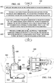
FIG. 1 illustrates a helicopter comprising an autorotative assist unit according to an embodiment of the disclosure; -
FIG. 2A is a schematic illustration of an autorotative assist unit according to an embodiment of the disclosure; -
FIG. 2B is a flowchart illustrating a method of providing autorotative assistance for a rotor helicopter; -
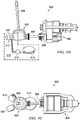
FIG. 3A is a side view of a system including the transmission, engine and rotor of a helicopter without an autorotative assist unit, shown within the helicopter; -
FIG. 3B is a side view of a system including the transmission, engine and rotor of a helicopter without an autorotative assist unit; -
FIG. 3C is a top view of a system including the transmission, engine and rotor of a helicopter without an autorotative assist unit; -
FIG. 3D is an perspective view of a system including the transmission, engine and rotor of a helicopter without an autorotative assist unit; -
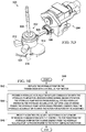
FIG. 4A is a side view of another system including the transmission, engine and rotor of a helicopter comprising an autorotative assist unit, shown within the helicopter; -
FIG. 4B is a side view of a system including the transmission, engine and rotor of a helicopter comprising an autorotative assist unit; -
FIG. 4C is a top view of a system including the transmission, engine and rotor of a helicopter comprising an autorotative assist unit; -
FIG. 4D is an perspective view of a system including the transmission, engine and rotor of a helicopter comprising an autorotative assist unit; -
FIG. 4E is a flowchart illustrating a method of retrofitting a helicopter for improved autorotation capabilities; -
FIG. 5A is a side view of yet another system including the transmission, engine and rotor of a helicopter comprising an autorotative assist unit, shown within the helicopter; -
FIG. 5B is a side view of a system including the transmission, engine and rotor of a helicopter comprising an autorotative assist unit; -
FIG. 5C is a top view of a system including the transmission, engine and rotor of a helicopter comprising an autorotative assist unit; -
FIG. 5D is an perspective view of a system including the transmission, engine and rotor of a helicopter comprising an autorotative assist unit; and -
FIG. 5E is a flowchart illustrating another method of retrofitting a helicopter for improved autorotation capabilities. - It should be understood at the outset that although an illustrative implementation of one or more embodiments are provided below, the disclosed systems and/or methods may be implemented using any number of techniques, whether currently known or in existence. The disclosure should in no way be limited to the illustrative implementations, drawings, and techniques illustrated below, including the exemplary designs and implementations illustrated and described herein, but may be modified within the scope of the appended claims along with their full scope of equivalents.
In some cases, it may be desirable to provide enhancement or assistance to the autorotation of a helicopter in the event of engine failure. An autorotative assist unit may be operable to enhance the safety of the descent and landing of a helicopter using autorotation. The autorotative assist unit may provide supplemental power to the rotor system of a helicopter during autorotation, such as a landing flare of energy operable to slow descent of a helicopter right before landing, for example. A landing flare may be used to execute a safe landing during autorotation. Design criteria for helicopters may require the ability to complete autorotation from a certain density altitude, such as around 2134 meters (7,000 feet), for example. To meet the criteria, an autorotative assist unit may be used to enhance the autorotative capabilities of the helicopter.
Referring toFIG. 1 , asystem 100 according to an embodiment of the disclosure is shown. Thesystem 100 comprises ahelicopter 120, wherein thehelicopter 120 comprises afuselage 121, atransmission 102, anengine 104 mechanically coupled to thetransmission 102, arotor system 108 mechanically coupled to thetransmission 102, and anautorotative assist unit 110 mechanically coupled to thetransmission 102. Therotor system 108 may comprise amast 107 coupled to thetransmission 102 androtor blades 109 coupled to themast 107. Thetransmission 102 may be coupled to theengine 104 via adrive shaft 105 and/or afreewheeling unit 106, wherein thefreewheeling unit 106 allows for free rotation of therotor 108 upon loss of power from the engine 104 (such may be needed to allow autorotation). Theengine 104 may comprise a turbine or piston engine, for example, and thehelicopter 120 may be a single engine helicopter or a multi-engine helicopter. In one embodiment, thehelicopter 120 may comprise a single engine helicopter with arotor 108. Theautorotative assist unit 110 is not typically used during normal engine operation (e.g. climb, cruise, hover, descent, etc.). Instead, theautorotative assist unit 110 may be operable to store energy (for example, excess engine energy not required to drive the rotor 108) during normal engine operation. In the event of failure of theengine 104, thefreewheeling unit 106 may disengage thetransmission 102 from theengine 104, and theautorotative assist unit 110 may be operable to provide power to thetransmission 102 and therefore the rotor 108 (as a supplement to normal autorotation). The autorotative assist unit can be applicable to all rotor hub types, but it may be particularly helpful in helicopters with articulated or low inertia rotors. - During autorotation, a pilot of the
helicopter 120 may control the energy output from theautorotative assist unit 110 to therotor 108, for example, deciding when to use the supplemental power from theautorotative assist unit 110 and/or how much of the availableautorotative assist unit 110 power to use. The flight crew may be provided with an indication of the amount of energy stored in theautorotative assist unit 110. In other embodiments, the output of energy may be controlled automatically by theautorotative assist unit 110. In some embodiments, a "landing flare" of energy from theautorotative assist unit 110 may be used to slow the descent of thehelicopter 120 right before landing. In other embodiments, energy from theautorotative assist unit 110 may be used to slow thehelicopter 120 throughout the descent and/or at the landing. Additionally, the energy input from theautorotative assist unit 110 may be used to stop descent, hover, level cruise, or possibly lift thehelicopter 120 if necessary (for example, to traverse an obstacle). Several different methods may be used to input the energy from theautorotative assist unit 110 to therotor 108 based on the conditions of the descent and landing and the abilities and decisions of the pilot of thehelicopter 120. - In some embodiments, the
autorotative assist unit 110 may respond to sensor input from sensors within thehelicopter 120 to automatically provide autorotative assistance. Sensors may provide information comprising engine revolutions per minute (rpm), rotor rpm, descent rate, and/or altitude, as well as energy stored in theautorotative assist unit 110. In one embodiment, theautorotative assist unit 110 may be triggered to provide autorotative assistance when the rpm level of theengine 104 falls below the rpm level of therotor 108. Autorotative assistance may also be controlled by a model or function executed by a controller coupled to theautorotative assist unit 110. - In some embodiments, the
autorotative assist unit 110 may comprise an electric motor-generator, a battery system electrically coupled to the motor-generator operable to store and discharge energy, and a controller operable to control autorotative assist by communicating commands from a pilot and/or receiving sensor data. In another embodiment, theautorotative assist unit 110 may comprise a hydraulic pump-motor, a hydraulic accumulator in fluid communication with the hydraulic pump-motor operable to store and discharge energy, and a controller operable to control release of the energy stored in the hydraulic accumulator. In yet another embodiment, theautorotative assist unit 110 may comprise a mechanical power storage system, such as a flywheel or spring arrangement, for example. - Referring now to
FIG. 2A , a schematic illustration of anautorotative assist system 200 is shown, according to an embodiment of the disclosure. Theautorotative assist system 200 may comprise atransmission 202, anengine 204 mechanically coupled to thetransmission 202 via afreewheeling unit 206, arotor 208 mechanically coupled to thetransmission 202, and anautorotative assist unit 210 mechanically coupled to the transmission 202 (typically without any intermediate gearing). In some embodiments, theautorotative assist unit 210 may comprise a motor-generator 212 mechanically coupled to thetransmission 202, abattery system 214 electrically coupled to the motor-generator 212, and acontroller 216 for operating the motor-generator 212. In an embodiment, thebattery system 214 may comprise a high capacity/high discharge rate battery system, such as a Lithium (Li) ion battery for example. Thebattery system 214 may be operable to store energy during normal operation of theengine 204 and discharge this energy for autorotative assistance. By having a high discharge rate, thebattery system 214 may allow for a boost of power for autorotative assistance. A high capacity/high dischargerate battery system 214 may be operable to recover energy in a short period of time, which may enable repeated autorotative assistance, such as may be used during a training exercise, for example. - The
controller 216 may be operable to communicate commands to the motor-generator 212 for directing the stored power in thebattery system 214 of theautorotative assist unit 210 to power the motor-generator 212 to drive therotor 208. In one embodiment, thecontroller 216 may receive commands from a pilot of the helicopter, for example. In other embodiments, thecontroller 216 may receive sensor input and, based on the sensor input, may automatically trigger the motor-generator 212 to provide autorotative assistance. Additionally, a combination of automatic and manual control of theautorotative assist unit 210 may be provided by thecontroller 216. In some embodiments, the energy input to therotor 208 may be spread out during the descent and/or the energy may be used during the landing flare. This control of the energy output may be scheduled by thecontroller 216, it may be triggered by a pilot, or a combination of the two may be used. For example, theautorotative assist unit 210 may automatically put the helicopter in an autorotative state when theengine 204 fails, and the energy remaining after doing so may be used at the discretion of the pilot. In some embodiments, theautorotative assist unit 210 may be operable to provide about 60 kW (80 hp) for about 6-7 seconds. In other embodiments, theautorotative assist unit 210 may be operable to provide about 34 kW (45 hp) for about 3-4 seconds. In yet other embodiments, theautorotative assist unit 210 may be operable to provide about 34-60 kW (45-80 hp) for about 3-7 seconds. In some embodiments, theautorotative assist unit 210 may weigh about 28-29 kg (62-64 pounds). Typically, the weight of such an autorotative assist unit may be less than the additional weight that would have to be added to the rotor to achieve rotational inertia for comparable autorotation landing performance.
Some embodiments of the disclosure includemethods 240, shown inFIG. 2B of providing autorotative assistance for a rotor helicopter, wherein the helicopter comprises anautorotative assist unit 210. Themethod 240 may comprise, atblock 244, placing the helicopter into autorotation upon loss of engine power. This may be done manually by the pilot or automatically by controls in the helicopter. Then, when necessary, themethod 240 may comprise, atblock 246, providing autorotative assistance to therotor 208 from theautorotative assist unit 210, thereby driving therotor 208 as a supplement to autorotation. In some embodiments, themethod 240 may also comprise, atblock 242, storing energy in theautorotative assist unit 210, such as in thebattery system 214, during normal engine operation (wherein the storing energy may precede the steps atblocks 244 and 246). Autorotative assistance may be triggered manually by pilot control and/or automatically based on sensor input, wherein the helicopter may comprise sensors operable to provide information to theautorotative assist unit 210, such as engine rpm, rotor rpm, speed, descent rate, and altitude, as well as energy stored in thebattery system 214. In some embodiments, the autorotative assistance comprises providing about 34 -60 kW (45-80 hp) for about 3-7 seconds to therotor 208. Autorotative assistance may be provided at landing flare and/or during the descent of the helicopter (prior to landing flare) to slow the descent of the helicopter. In some embodiments, themethod 240 may further comprise, atblock 248, after use of theautorotative assist unit 210, recharging the stored energy in the autorotative assist unit 210 (such as in the battery system 214) after discharge. The step of recharging may be used in training for autorotation, for example. - Referring now to
FIGS. 3A-3D , different views of arotor drive system 300 within drive system compartment(s) 320 that does not comprise an autorotative assist unit are shown. Thetransmission 302 may be coupled to the rotor 308 (or mast of the rotor system) and to theengine 304 via adrive shaft 305 and a free-wheelingunit 306. The free-wheelingunit 306 may be operable to disengage theengine 304 from thetransmission 302 upon engine failure to allow for autorotation. Thetransmission 302 may also be coupled to ahydraulic pump system 322 and anelectric generator 324. Thehydraulic pump system 322 andelectric generator 324 may couple to thetransmission 302 independently of thedrive shaft 305 or the free-wheelingunit 306. - Referring now to
FIGS. 4A-4D , a detailed view of asystem 400 comprising an electrically-basedautorotative assist unit 410 is shown. Similarly to thesystem 300 shown inFIGS. 3A-3D , thetransmission 402 is coupled to theengine 404, via adrive shaft 405 and a free-wheelingunit 406, and to the rotor 408 (or mast of the rotor system). Thetransmission 402 may also be coupled to ahydraulic pump system 422 and anautorotative assist unit 410. Theautorotative assist unit 410 may comprise a motor-generator 412, abattery system 414 and acontroller 416. In some embodiments, the motor-generator 412 of theautorotative assist unit 410 may take the place of an electric generator 324 (as shown inFIGS. 3A-3D ). - Some embodiments of the disclosure may include methods, as shown in
FIG. 4E of retrofitting a helicopter for improved autorotation capabilities, wherein thehelicopter 420 comprises arotor 408, atransmission 402 having a generator 324 (as shown inFIGS. 3A-3D ) off thetransmission housing 402, and anengine 404. Themethod 440 may comprise, atblock 442, replacing thegenerator 324 on thetransmission 402 with a motor-generator 412. Then, atblock 444, the method may comprise providing a high capacity/high dischargerate battery system 414, wherein, in some embodiments, thenew battery system 414 may replace a portion of the battery system already existing in thehelicopter 420. The method may then comprise, atblock 446, electrically connecting the motor-generator 412 to thebattery system 414 so that during normal engine operation, the motor-generator 412 charges thebattery system 414, but upon loss of engine power, the motor-generator 412 is operable to draw energy from thebattery system 414 to drive therotor 408 for autorotative assistance. Additionally, thetransmission 402 may couple to a free-wheelingunit 406, and the motor-generator 412 and theengine 404 may be coupled to thetransmission 402 on opposite sides of thefreewheeling unit 406. In other words, the motor-generator 412 may be coupled to thetransmission 402 independently of a drive shaft 405 (and/or free-wheeling unit 406) from theengine 404. Typically, the motor-generator 412 may be coupled to the transmission without any intervening components, such as gearing. The method may additionally comprise, atblock 448, providing acontroller 416, as well as optionally one or more sensors in communication with thecontroller 416, for triggering the motor-generator 412 to draw energy from thebattery system 414 to provide power to therotor 408 during autorotation. In some embodiments, the motor-generator 412 andbattery system 414 may be operable to provide about 34-60 kW (45-80 hp) to therotor 408 for about 3-7 seconds during autorotation. Additionally, the motor-generator 412 andbattery system 414 may weigh no more than about 29.5 kg (65 pounds), for example about 27-29.5 kg (60-65 pounds), in some embodiments. - Referring now to
FIGS. 5A-5D , a detailed view of asystem 500, not covered in isolation by the present invention, comprising a hydraulically-basedautorotative assist unit 510 is shown within drive system compartment(s) 520. Similarly to thesystem 300 shown inFIGS. 3A-3D , thetransmission 502 is coupled to theengine 504, via adrive shaft 505 and a free-wheelingunit 506, and to the rotor 508 (or mast of the rotor system). Thetransmission 502 may also be coupled to anelectric generator 524 and anautorotative assist unit 510. Theautorotative assist unit 510 may comprise a hydraulic pump-motor 512, ahydraulic accumulator 514 and acontroller 516. In some embodiments, hydraulic pump-motor 512 of theautorotative assist unit 510 may take the place of a hydraulic pump system 322 (as shown inFIGS. 3A-3D ). Although not specifically shown, it should be understood that the AAU in some embodiments may comprises both electrical and hydraulic features. - Some embodiments of the disclosure may include methods, shown in
FIG. 5E , of retrofitting a helicopter for improved autorotation capabilities, wherein the helicopter comprises arotor 508, atransmission 502 having a hydraulic pump 322 (as shown inFIGS. 3A-3D ) off thetransmission housing 502, and anengine 504. Themethod 540 may comprise, atblock 542, replacing thehydraulic pump 322 on thetransmission 502 with a hydraulic pump-motor 512. Then, atblock 544, the method may comprise providing ahydraulic accumulator 514 in fluid communication with the hydraulic pump-motor 512, wherein during normal engine operation, the hydraulic pump-motor 512 pressurizes (e.g. stores hydraulic energy in) thehydraulic accumulator 514, but upon loss of engine power, the hydraulic pump-motor 512 draws pressure (energy) from thehydraulic accumulator 514 to drive the rotor for autorotative assistance. In some embodiments, thehydraulic accumulator 514 may comprise a pressure vessel. Additionally, thetransmission 502 may couple to a free-wheelingunit 506 and the hydraulic pump-motor 512 and theengine 504 may be coupled to thetransmission 502 on opposite sides of thefreewheeling unit 506. In other words, the hydraulic pump-motor 512 may be coupled to thetransmission 502 independently of adrive shaft 505 from theengine 504. Typically, the pump-motor may be coupled to the transmission without any intervening components, such as gearing. The method may additionally comprise, atblock 546, providing acontroller 516, as well as optionally one or more sensors in communication with thecontroller 516, for triggering the hydraulic pump-motor 512 to draw energy from thehydraulic accumulator 514 to provide power to therotor 508 during autorotation. In some embodiments, the hydraulic pump-motor 512 andhydraulic accumulator 514 may be operable to provide about 34-60 kW (45-80 hp) to therotor 508 for about 3-7 seconds during autorotation. Additionally, the hydraulic pump-motor 512 andhydraulic accumulator 514 may weigh less than about 29.5 kg (65 pounds), for example about 27-29.5 kg (60-65 pounds), in some embodiments. - As has been described above and shown in the figures, certain embodiments of the disclosure include a shim that is used to bond a component to a bearing. The shim may have an elastic modulus value that is lower than an elastic modulus value of the component being bonded to the bearing. In such a case, as torsional strain is applied to the component, the shim absorbs a portion of the torsional strain. This reduces an amount of torsional strain experienced by an adhesive layer. Accordingly, since the amount of torsional strain in the adhesive layer is reduced, the adhesive layer may be less likely to fail during operation and may require less maintenance. Additionally, the use of a shim may be advantageous in that it can replace custom molded bearings and components, which may have long lead times and be difficult to assemble and replace.
- Where numerical ranges or limitations are expressly stated, such express ranges or limitations should be understood to include iterative ranges or limitations of like magnitude falling within the expressly stated ranges or limitations (e.g., from about 1 to about 10 includes, 2, 3, 4, etc.; greater than 0.10 includes 0.11, 0.12, 0.13, etc.). For example, whenever a numerical range with a lower limit, Rl, and an upper limit, Ru, is disclosed, any number falling within the range is specifically disclosed. In particular, the following numbers within the range are specifically disclosed: R=Rl+k*(Ru-R1), wherein k is a variable ranging from 1 percent to 100 percent with a 1 percent increment, i.e., k is 1 percent, 2 percent, 3 percent, 4 percent, 5 percent, ..., 50 percent, 51 percent, 52 percent, ..., 95 percent, 96 percent, 97 percent, 98 percent, 99 percent, or 100 percent. Unless otherwise stated, the term "about" shall mean plus or minus 10 percent of the subsequent value. Moreover, any numerical range defined by two R numbers as defined in the above is also specifically disclosed. Use of the term "optionally" with respect to any element of a claim means that the element is required, or alternatively, the element is not required, both alternatives being within the scope of the claim. Use of broader terms such as comprises, includes, and having should be understood to provide support for narrower terms such as consisting of, consisting essentially of, and comprised substantially of. Accordingly, the scope of protection is not limited by the description set out above but is defined by the claims that follow, that scope including all equivalents of the subject matter of the claims. Each and every claim is incorporated as further disclosure into the specification and the claims are embodiment(s) of the present invention.
Claims (10)
- An autorotative assist system (200) comprising:a motor-generator (212) configured to attach to a transmission (202) of an engine (204), the engine (204) configured to rotate rotor blades connected to the transmission (202); andan energy storage unit (214) coupled to the motor-generator (212),wherein, during normal operation of the engine (204), the motor-generator (212) is configured to convert energy from the transmission (202) into electrical energy, and the energy storage unit (214) is configured to receive and store (242) the electrical energy, andwherein, upon loss of engine power, the energy storage unit (214) is configured to provide the stored energy to the motor-generator (212), and the motor-generator (212) is configured to be powered by the energy received from the energy storage unit (214) to drive the transmission (202) to provide supplemental autorotative assistance (246) to rotate the rotor blades, wherein the motor-generator (212) and energy storage unit (214) are configured to provide about 34-60 kW (45-80 hp) for about 3-7 seconds, the autoroatative assist system (200) further comprising:a controller (216) connected to the motor-generator (212) and the energy storage unit (214), the controller (216) configured to control the supplemental autorotative assistance provided upon loss of engine power; andone or more sensors in communication with the controller, the one or more sensors for triggering the motor-generator (212) to draw energy from the energy storage unit (214) to provide power to the rotor blades during autorotation.
- The system (200) of claim 1, wherein, during normal operation, the motor-generator (212) is configured to operate as a generator to provide electric power to the transmission (202).
- The system (200) of claim 1, wherein the energy storage unit comprises a high capacity/high discharge rate battery system (214).
- The system (200) of claim 1, further comprising a hydraulic pump system (512, 514) connected to the transmission (202).
- The system of any preceding claim, wherein the one or more sensors provide sensor data comprising at least one of engine revolutions per minute, rotor revolutions per minute, descent rate, altitude, or energy stored in the energy storage unit (214).
- A method of providing autorotative assistance, the method comprising:during normal operation of an engine (204) driving a transmission (202) to rotate rotor blades (208):converting energy from the transmission (202) into electrical energy using a motor-generator (212) coupled to the transmission (202), andstoring the energy in an energy storage unit (214) coupled to the motor-generator (212), andupon loss of engine power,providing stored energy from the energy storage unit (214) to the motor-generator (212), andoperating the motor-generator (212) using the stored energy to drive the rotor blades (208) through the transmission (202) to provide supplemental autorotative assistance, wherein the motor-generator (212) and energy storage unit (214) are configured to provide about 34-60 kW (45-80 hp) for about 3-7 seconds, and wherein the method further comprises:controlling the supplemental autorotative assistance provided upon loss of engine power using a controller (216) connected to the motor-generator (212) and the energy storage unit (214); andtriggering, by one or more sensors in communication with the controller, the motor-generator (212) to draw energy from the energy storage unit (214) to provide power to the rotor blades during autorotation.
- The method of claim 6, wherein, before the loss of the engine power and during normal operation of the engine (204), the motor-generator (212) converts energy from the transmission (202) into electrical energy and the energy storage unit (214) stores the energy.
- The method of claim 6 or claim 7, further comprising directing stored energy from a hydraulic accumulator to a hydraulic pump-motor (512), to drive the rotor blades (208).
- The method of claim 6 or claim 7, further comprising, during normal operation, operating the motor-generator (212) as a generator to provide electric power to the transmission (202).
- The method of any of claims 6 to 9 wherein the one or more sensors provide sensor data comprising at least one of engine revolutions per minute, rotor revolutions per minute, descent rate, altitude, or energy stored in the energy storage unit (214).
Priority Applications (2)
| Application Number | Priority Date | Filing Date | Title |
|---|---|---|---|
| EP20209609.5A EP3800119B1 (en) | 2013-03-15 | 2013-06-11 | Autorotative enhancement system |
| EP18193690.7A EP3434587B1 (en) | 2013-03-15 | 2013-06-11 | Autorotative enhancement system |
Applications Claiming Priority (2)
| Application Number | Priority Date | Filing Date | Title |
|---|---|---|---|
| US13/834,215 US9180964B2 (en) | 2013-03-15 | 2013-03-15 | Autorotative enhancement system |
| EP13171571.6A EP2778048B1 (en) | 2013-03-15 | 2013-06-11 | Autorotative enhancement system |
Related Parent Applications (2)
| Application Number | Title | Priority Date | Filing Date |
|---|---|---|---|
| EP13171571.6A Division-Into EP2778048B1 (en) | 2013-03-15 | 2013-06-11 | Autorotative enhancement system |
| EP13171571.6A Division EP2778048B1 (en) | 2013-03-15 | 2013-06-11 | Autorotative enhancement system |
Related Child Applications (3)
| Application Number | Title | Priority Date | Filing Date |
|---|---|---|---|
| EP18193690.7A Division EP3434587B1 (en) | 2013-03-15 | 2013-06-11 | Autorotative enhancement system |
| EP18193690.7A Division-Into EP3434587B1 (en) | 2013-03-15 | 2013-06-11 | Autorotative enhancement system |
| EP20209609.5A Division EP3800119B1 (en) | 2013-03-15 | 2013-06-11 | Autorotative enhancement system |
Publications (2)
| Publication Number | Publication Date |
|---|---|
| EP3000730A1 EP3000730A1 (en) | 2016-03-30 |
| EP3000730B1 true EP3000730B1 (en) | 2018-12-19 |
Family
ID=48628297
Family Applications (4)
| Application Number | Title | Priority Date | Filing Date |
|---|---|---|---|
| EP13171571.6A Active EP2778048B1 (en) | 2013-03-15 | 2013-06-11 | Autorotative enhancement system |
| EP18193690.7A Active EP3434587B1 (en) | 2013-03-15 | 2013-06-11 | Autorotative enhancement system |
| EP20209609.5A Active EP3800119B1 (en) | 2013-03-15 | 2013-06-11 | Autorotative enhancement system |
| EP15194261.2A Active EP3000730B1 (en) | 2013-03-15 | 2013-06-11 | Autorotative enhancement system |
Family Applications Before (3)
| Application Number | Title | Priority Date | Filing Date |
|---|---|---|---|
| EP13171571.6A Active EP2778048B1 (en) | 2013-03-15 | 2013-06-11 | Autorotative enhancement system |
| EP18193690.7A Active EP3434587B1 (en) | 2013-03-15 | 2013-06-11 | Autorotative enhancement system |
| EP20209609.5A Active EP3800119B1 (en) | 2013-03-15 | 2013-06-11 | Autorotative enhancement system |
Country Status (2)
| Country | Link |
|---|---|
| US (5) | US9180964B2 (en) |
| EP (4) | EP2778048B1 (en) |
Cited By (1)
| Publication number | Priority date | Publication date | Assignee | Title |
|---|---|---|---|---|
| US11059598B2 (en) | 2017-06-01 | 2021-07-13 | Moog Inc. | Auxiliary power system for rotorcraft with folding propeller arms and crumple zone loading gear |
Families Citing this family (39)
| Publication number | Priority date | Publication date | Assignee | Title |
|---|---|---|---|---|
| DE102012014751B3 (en) * | 2012-07-26 | 2014-01-02 | Eads Deutschland Gmbh | Auxiliary propulsion system for a helicopter |
| US9180964B2 (en) | 2013-03-15 | 2015-11-10 | Bell Helicopter Textron Inc. | Autorotative enhancement system |
| US9242727B1 (en) * | 2014-09-22 | 2016-01-26 | Rockwell Collins, Inc. | Autorotation initiation and flare cues system and related method |
| EP3197773A4 (en) * | 2014-09-23 | 2018-02-21 | Sikorsky Aircraft Corporation | Hybrid electric power drive system for a rotorcraft |
| US10040566B2 (en) * | 2014-09-23 | 2018-08-07 | Sikorsky Aircraft Corporation | Hybrid contingency power drive system |
| US20170267338A1 (en) | 2014-10-01 | 2017-09-21 | Sikorsky Aircraft Corporation | Acoustic signature variation of aircraft utilizing a clutch |
| EP3034834B1 (en) * | 2014-12-16 | 2019-04-10 | Airbus (Sas) | Method for managing power demand for the operation of an unmanned aircraft provided with an internal combustion engine |
| US20180002005A1 (en) * | 2015-01-21 | 2018-01-04 | Felix Errol Groenewald | Aircraft |
| KR101615486B1 (en) * | 2015-07-17 | 2016-04-26 | 주식회사 한국카본 | Vertical take off and landing aircraft using hybrid-electric propulsion system |
| US10854316B2 (en) * | 2015-12-03 | 2020-12-01 | Syracuse University | Methods and systems for prediction of a DNA profile mixture ratio |
| CN105836116B (en) * | 2016-04-07 | 2019-02-19 | 易瓦特科技股份公司 | Cooling type unmanned plane |
| EP3246527B1 (en) * | 2016-05-18 | 2019-08-14 | Rolls-Royce Corporation | Low pressure generator for gas turbine engine |
| US11194349B2 (en) | 2016-06-27 | 2021-12-07 | Sikorsky Aircraft Corporation | Automated autorotation and pilot aiding system |
| CA3028598A1 (en) * | 2016-07-06 | 2018-01-11 | Martin Kuster | Helicopter hybrid engine system |
| US11022042B2 (en) | 2016-08-29 | 2021-06-01 | Rolls-Royce North American Technologies Inc. | Aircraft having a gas turbine generator with power assist |
| WO2018175349A1 (en) * | 2017-03-19 | 2018-09-27 | Zunum Aero, Inc. | Hybrid-electric aircraft, and methods, apparatus and systems for facilitating same |
| US11186185B2 (en) | 2017-05-31 | 2021-11-30 | Textron Innovations Inc. | Rotor brake effect by using electric distributed anti-torque generators and opposing electric motor thrust to slow a main rotor |
| US11001384B2 (en) | 2017-10-02 | 2021-05-11 | Bell Helicopter Textron Inc. | Hybrid power systems for aircraft |
| GB2567158A (en) * | 2017-10-03 | 2019-04-10 | J And M Ferranti Tech Limited | Power generation and drive system |
| US10906637B2 (en) | 2018-05-17 | 2021-02-02 | Textron Innovations Inc. | Assisted landing systems for rotorcraft |
| KR102101013B1 (en) * | 2018-09-19 | 2020-04-14 | 전상엽 | Hybrid tandem helicopter type drone |
| US11148799B2 (en) * | 2018-11-26 | 2021-10-19 | Textron Innovations Inc. | Tilting duct compound helicopter |
| RU2694695C1 (en) * | 2018-12-05 | 2019-07-16 | Шамиль Абдулбарович Сулейманов | Method of distribution and control of rotorcraft with helicopter drive hybrid system |
| FR3090576B1 (en) | 2018-12-20 | 2021-09-10 | Airbus Helicopters | Assistance method for single-engine rotary-wing aircraft during engine failure. |
| KR102219558B1 (en) * | 2018-12-24 | 2021-02-23 | 에어버스 헬리콥터스 | A hybrid type rotorcraft having a horizontal stabilizer and two fins arranged on the horizontal stabilizer |
| KR101970601B1 (en) * | 2019-03-13 | 2019-04-19 | 문창모 | Vertical takeoff and landing aircraft using hybrid-electric propulsion system |
| US11352900B2 (en) * | 2019-05-14 | 2022-06-07 | Pratt & Whitney Canada Corp. | Method and system for operating a rotorcraft engine |
| CN110435883B (en) * | 2019-07-26 | 2023-10-31 | 佛山科学技术学院 | A side-by-side reverse twin-rotor helicopter transmission system |
| US11104430B2 (en) * | 2019-09-27 | 2021-08-31 | Textron Innovations Inc. | Multimode powertrains for multi engine rotorcraft |
| FR3106570B1 (en) | 2020-01-23 | 2024-02-16 | Airbus Helicopters | rotary wing aircraft equipped with a transmission system equipped with an emergency electric motor. |
| FR3114077B1 (en) | 2020-09-14 | 2024-01-19 | Airbus Helicopters | Method and device for managing the energy supplied by a hybrid power plant for a rotorcraft |
| FR3116805B1 (en) * | 2020-11-30 | 2022-12-23 | Airbus Helicopters | powerplant for a rotary-wing aircraft equipped with an engine brake as well as a freewheel and a parallel disengageable connection |
| IL289148A (en) * | 2021-12-19 | 2023-07-01 | De Israeli Luca | Conversion of conventional airplane to electrical propulsion airplane |
| FR3135249B1 (en) * | 2022-05-09 | 2026-08-07 | Safran Helicopter Engines | Operating method of a propulsion system for an aircraft |
| FR3145553B1 (en) * | 2023-02-08 | 2025-01-10 | Airbus Helicopters | Method for testing a hybrid power plant equipping an aircraft, associated computer program and aircraft |
| US12473843B2 (en) * | 2023-02-13 | 2025-11-18 | Pratt & Whitney Canada Corp. | Hybrid electric propulsion system with pitch change mechanism operation |
| EP4467449B1 (en) * | 2023-05-24 | 2025-10-15 | AIRBUS HELICOPTERS DEUTSCHLAND GmbH | A method of operating a rotorcraft in a single engine operation mode |
| CN117184435B (en) * | 2023-08-16 | 2025-11-25 | 中国直升机设计研究所 | A rotor rotational inertia design method based on autorotation landing capability |
| EP4631851B1 (en) | 2024-04-11 | 2026-06-17 | AIRBUS HELICOPTERS DEUTSCHLAND GmbH | A rotorcraft with an autorotation training mode control system |
Family Cites Families (26)
| Publication number | Priority date | Publication date | Assignee | Title |
|---|---|---|---|---|
| US3027704A (en) | 1959-07-24 | 1962-04-03 | United Aircraft Corp | Power and starting system for engines |
| GB1015512A (en) | 1962-08-20 | 1966-01-05 | Rolls Royce | Improvements in or relating to suspension systems for vehicles |
| US3260313A (en) * | 1964-05-28 | 1966-07-12 | Harold H Reuther | Helicopter flight controls |
| FR1422328A (en) * | 1964-11-13 | 1965-12-24 | Sud Aviation | Improvements in power transmission mechanisms and their applications, particularly in helicopters |
| US3455182A (en) * | 1967-04-12 | 1969-07-15 | Garrett Corp | Helicopter lift augmentation means |
| US4046335A (en) * | 1975-06-26 | 1977-09-06 | Helmut Osberger | Helicopters safety drive |
| US4609165A (en) | 1983-04-25 | 1986-09-02 | Hughes Helicopters, Inc. | Helicopter auxiliary energy system |
| FR2645828B1 (en) * | 1989-04-17 | 1991-06-21 | Servanty Pierre | ROTOR CAPABLE OF DEVELOPING LIFT AND / OR PROPELLANT EFFORTS IN A FLUID, PILOTAGE PROCESS AND AIRCRAFT EQUIPPED WITH SUCH A ROTOR |
| GB0108659D0 (en) * | 2001-04-06 | 2001-05-30 | Westland Helicopters | Improvements in or relating to aircrafts |
| FR2922860B1 (en) * | 2007-10-26 | 2010-01-22 | Eurocopter France | IMPROVEMENT TO GIRAVIONS EQUIPPED WITH TURBOMOTORS |
| US8727271B2 (en) * | 2008-01-11 | 2014-05-20 | Ival O. Salyer | Aircraft using turbo-electric hybrid propulsion system |
| DE102008014404B4 (en) * | 2008-03-14 | 2011-03-03 | Swiss Uav Gmbh | Unmanned aerial vehicle |
| US20090320460A1 (en) * | 2008-06-26 | 2009-12-31 | Robert Peterson | Aircraft Auxiliary Systems Pump |
| FR2933910B1 (en) | 2008-07-18 | 2010-12-17 | Eurocopter France | HYBRID POWER PLANT AND METHOD FOR CONTROLLING SUCH A MOTOR INSTALLATION |
| WO2010123601A1 (en) * | 2009-01-27 | 2010-10-28 | Kuhn Ira F Jr | Purebred and hybrid electric vtol tilt rotor aircraft |
| FR2952907B1 (en) | 2009-11-26 | 2011-12-09 | Eurocopter France | MOTOR INSTALLATION, HELICOPTER COMPRISING SUCH A MOTOR INSTALLATION, AND METHOD IMPLEMENTED BY THIS MOTOR INSTALLATION |
| DE102010021026A1 (en) * | 2010-05-19 | 2011-11-24 | Eads Deutschland Gmbh | Hybrid propulsion and power system for aircraft |
| FR2962404B1 (en) * | 2010-07-08 | 2012-07-20 | Eurocopter France | ELECTRICAL ARCHITECTURE FOR AN AIRCRAFT WITH A HYBRID MOTORIZED TURNING SAIL |
| JP5352745B2 (en) * | 2010-11-04 | 2013-11-27 | トヨタ自動車株式会社 | Control device for hybrid vehicle |
| US20130134264A1 (en) * | 2011-11-28 | 2013-05-30 | Carter Aviation Technologies, Llc | Electric Motor Powered Rotor Drive for Slowed Rotor Winged Aircraft |
| US20130134253A1 (en) * | 2011-11-28 | 2013-05-30 | Carter Aviation Technologies, Llc | Power Rotor Drive for Slowed Rotor Winged Aircraft |
| DE102012014751B3 (en) * | 2012-07-26 | 2014-01-02 | Eads Deutschland Gmbh | Auxiliary propulsion system for a helicopter |
| US8939399B2 (en) * | 2012-07-31 | 2015-01-27 | Textron Innovations Inc. | System and method of augmenting power in a rotorcraft |
| FR2994687B1 (en) * | 2012-08-27 | 2014-07-25 | Eurocopter France | METHOD FOR ASSISTING A PILOT OF A ROTARY VESSEL FLYING MONOMOTER AIRCRAFT DURING A FLIGHT PHASE IN AUTOROTATION |
| US9180964B2 (en) | 2013-03-15 | 2015-11-10 | Bell Helicopter Textron Inc. | Autorotative enhancement system |
| US9193451B2 (en) * | 2013-04-22 | 2015-11-24 | Ival O. Salyer | Aircraft using turbo-electric hybrid propulsion system for multi-mode operation |
-
2013
- 2013-03-15 US US13/834,215 patent/US9180964B2/en active Active
- 2013-06-11 EP EP13171571.6A patent/EP2778048B1/en active Active
- 2013-06-11 EP EP18193690.7A patent/EP3434587B1/en active Active
- 2013-06-11 EP EP20209609.5A patent/EP3800119B1/en active Active
- 2013-06-11 EP EP15194261.2A patent/EP3000730B1/en active Active
-
2015
- 2015-11-06 US US14/934,477 patent/US9522730B2/en active Active
-
2016
- 2016-12-19 US US15/383,458 patent/US10077105B2/en active Active
-
2018
- 2018-08-14 US US16/103,083 patent/US11014655B2/en active Active
-
2021
- 2021-05-13 US US17/319,629 patent/US20210276701A1/en not_active Abandoned
Non-Patent Citations (1)
| Title |
|---|
| None * |
Cited By (1)
| Publication number | Priority date | Publication date | Assignee | Title |
|---|---|---|---|---|
| US11059598B2 (en) | 2017-06-01 | 2021-07-13 | Moog Inc. | Auxiliary power system for rotorcraft with folding propeller arms and crumple zone loading gear |
Also Published As
| Publication number | Publication date |
|---|---|
| US20160059957A1 (en) | 2016-03-03 |
| US20140263820A1 (en) | 2014-09-18 |
| US20210276701A1 (en) | 2021-09-09 |
| EP2778048B1 (en) | 2016-01-13 |
| US20170096219A1 (en) | 2017-04-06 |
| EP3800119B1 (en) | 2022-09-21 |
| US9180964B2 (en) | 2015-11-10 |
| EP3434587B1 (en) | 2021-08-11 |
| US11014655B2 (en) | 2021-05-25 |
| EP3434587A1 (en) | 2019-01-30 |
| EP3800119A1 (en) | 2021-04-07 |
| EP3000730A1 (en) | 2016-03-30 |
| EP2778048A1 (en) | 2014-09-17 |
| US9522730B2 (en) | 2016-12-20 |
| US10077105B2 (en) | 2018-09-18 |
| US20180362152A1 (en) | 2018-12-20 |
Similar Documents
| Publication | Publication Date | Title |
|---|---|---|
| US11014655B2 (en) | Autorotative enhancement system | |
| US9045223B2 (en) | Method of assisting a pilot of a single-engined rotary wing aircraft during a stage of flight in autorotation | |
| US10301011B2 (en) | Electrified rotorcraft | |
| US10661896B2 (en) | Helicopter | |
| US10759280B2 (en) | Hybrid electric power drive system for a rotorcraft | |
| US10040566B2 (en) | Hybrid contingency power drive system | |
| US10583929B2 (en) | Helicopter with battery abnormality detection capability | |
| EP2636596B1 (en) | Engine starting system for rotorcraft in flight | |
| US8939399B2 (en) | System and method of augmenting power in a rotorcraft | |
| EP2962885B1 (en) | Hybrid power system for piston engine aircrafts | |
| KR101313851B1 (en) | An electrical architecture for a rotary wing aircraft with a hybrid power plant | |
| EP2735507B1 (en) | A mobile power plant, an application of such a power plant and a method of operating such a power plant | |
| US11634235B1 (en) | Electrically powered rotorcraft capable of autorotative landing | |
| US20150298797A1 (en) | Aircraft Having A System For Influencing The Yaw Moment And A Method For Influencing The Yaw Moment Of An Aircraft | |
| US11964771B2 (en) | Rotorcraft autorotation control through electrical braking | |
| CN109398690B (en) | Emergency escape power assisting system of aero-engine | |
| CN109250078A (en) | A kind of oil electricity mixing multi-rotor aerocraft | |
| RU210136U1 (en) | HELICOPTER RESCUE DEVICE | |
| JP2006335185A (en) | Apparatus and method for autorotation control of small unmanned helicopter aircraft |
Legal Events
| Date | Code | Title | Description |
|---|---|---|---|
| PUAI | Public reference made under article 153(3) epc to a published international application that has entered the european phase |
Free format text: ORIGINAL CODE: 0009012 |
|
| 17P | Request for examination filed |
Effective date: 20151112 |
|
| AC | Divisional application: reference to earlier application |
Ref document number: 2778048 Country of ref document: EP Kind code of ref document: P |
|
| AK | Designated contracting states |
Kind code of ref document: A1 Designated state(s): AL AT BE BG CH CY CZ DE DK EE ES FI FR GB GR HR HU IE IS IT LI LT LU LV MC MK MT NL NO PL PT RO RS SE SI SK SM TR |
|
| STAA | Information on the status of an ep patent application or granted ep patent |
Free format text: STATUS: EXAMINATION IS IN PROGRESS |
|
| GRAP | Despatch of communication of intention to grant a patent |
Free format text: ORIGINAL CODE: EPIDOSNIGR1 |
|
| STAA | Information on the status of an ep patent application or granted ep patent |
Free format text: STATUS: GRANT OF PATENT IS INTENDED |
|
| INTG | Intention to grant announced |
Effective date: 20180515 |
|
| GRAS | Grant fee paid |
Free format text: ORIGINAL CODE: EPIDOSNIGR3 |
|
| GRAJ | Information related to disapproval of communication of intention to grant by the applicant or resumption of examination proceedings by the epo deleted |
Free format text: ORIGINAL CODE: EPIDOSDIGR1 |
|
| GRAL | Information related to payment of fee for publishing/printing deleted |
Free format text: ORIGINAL CODE: EPIDOSDIGR3 |
|
| STAA | Information on the status of an ep patent application or granted ep patent |
Free format text: STATUS: EXAMINATION IS IN PROGRESS |
|
| GRAR | Information related to intention to grant a patent recorded |
Free format text: ORIGINAL CODE: EPIDOSNIGR71 |
|
| STAA | Information on the status of an ep patent application or granted ep patent |
Free format text: STATUS: GRANT OF PATENT IS INTENDED |
|
| INTC | Intention to grant announced (deleted) | ||
| INTG | Intention to grant announced |
Effective date: 20181011 |
|
| GRAA | (expected) grant |
Free format text: ORIGINAL CODE: 0009210 |
|
| STAA | Information on the status of an ep patent application or granted ep patent |
Free format text: STATUS: THE PATENT HAS BEEN GRANTED |
|
| AC | Divisional application: reference to earlier application |
Ref document number: 2778048 Country of ref document: EP Kind code of ref document: P |
|
| AK | Designated contracting states |
Kind code of ref document: B1 Designated state(s): AL AT BE BG CH CY CZ DE DK EE ES FI FR GB GR HR HU IE IS IT LI LT LU LV MC MK MT NL NO PL PT RO RS SE SI SK SM TR |
|
| REG | Reference to a national code |
Ref country code: GB Ref legal event code: FG4D |
|
| REG | Reference to a national code |
Ref country code: CH Ref legal event code: EP |
|
| REG | Reference to a national code |
Ref country code: IE Ref legal event code: FG4D |
|
| REG | Reference to a national code |
Ref country code: DE Ref legal event code: R096 Ref document number: 602013048615 Country of ref document: DE |
|
| REG | Reference to a national code |
Ref country code: AT Ref legal event code: REF Ref document number: 1078410 Country of ref document: AT Kind code of ref document: T Effective date: 20190115 |
|
| REG | Reference to a national code |
Ref country code: NL Ref legal event code: MP Effective date: 20181219 |
|
| PG25 | Lapsed in a contracting state [announced via postgrant information from national office to epo] |
Ref country code: HR Free format text: LAPSE BECAUSE OF FAILURE TO SUBMIT A TRANSLATION OF THE DESCRIPTION OR TO PAY THE FEE WITHIN THE PRESCRIBED TIME-LIMIT Effective date: 20181219 Ref country code: LV Free format text: LAPSE BECAUSE OF FAILURE TO SUBMIT A TRANSLATION OF THE DESCRIPTION OR TO PAY THE FEE WITHIN THE PRESCRIBED TIME-LIMIT Effective date: 20181219 Ref country code: FI Free format text: LAPSE BECAUSE OF FAILURE TO SUBMIT A TRANSLATION OF THE DESCRIPTION OR TO PAY THE FEE WITHIN THE PRESCRIBED TIME-LIMIT Effective date: 20181219 Ref country code: BG Free format text: LAPSE BECAUSE OF FAILURE TO SUBMIT A TRANSLATION OF THE DESCRIPTION OR TO PAY THE FEE WITHIN THE PRESCRIBED TIME-LIMIT Effective date: 20190319 Ref country code: LT Free format text: LAPSE BECAUSE OF FAILURE TO SUBMIT A TRANSLATION OF THE DESCRIPTION OR TO PAY THE FEE WITHIN THE PRESCRIBED TIME-LIMIT Effective date: 20181219 Ref country code: NO Free format text: LAPSE BECAUSE OF FAILURE TO SUBMIT A TRANSLATION OF THE DESCRIPTION OR TO PAY THE FEE WITHIN THE PRESCRIBED TIME-LIMIT Effective date: 20190319 |
|
| REG | Reference to a national code |
Ref country code: LT Ref legal event code: MG4D |
|
| REG | Reference to a national code |
Ref country code: AT Ref legal event code: MK05 Ref document number: 1078410 Country of ref document: AT Kind code of ref document: T Effective date: 20181219 |
|
| PG25 | Lapsed in a contracting state [announced via postgrant information from national office to epo] |
Ref country code: RS Free format text: LAPSE BECAUSE OF FAILURE TO SUBMIT A TRANSLATION OF THE DESCRIPTION OR TO PAY THE FEE WITHIN THE PRESCRIBED TIME-LIMIT Effective date: 20181219 Ref country code: GR Free format text: LAPSE BECAUSE OF FAILURE TO SUBMIT A TRANSLATION OF THE DESCRIPTION OR TO PAY THE FEE WITHIN THE PRESCRIBED TIME-LIMIT Effective date: 20190320 Ref country code: SE Free format text: LAPSE BECAUSE OF FAILURE TO SUBMIT A TRANSLATION OF THE DESCRIPTION OR TO PAY THE FEE WITHIN THE PRESCRIBED TIME-LIMIT Effective date: 20181219 Ref country code: AL Free format text: LAPSE BECAUSE OF FAILURE TO SUBMIT A TRANSLATION OF THE DESCRIPTION OR TO PAY THE FEE WITHIN THE PRESCRIBED TIME-LIMIT Effective date: 20181219 |
|
| PG25 | Lapsed in a contracting state [announced via postgrant information from national office to epo] |
Ref country code: NL Free format text: LAPSE BECAUSE OF FAILURE TO SUBMIT A TRANSLATION OF THE DESCRIPTION OR TO PAY THE FEE WITHIN THE PRESCRIBED TIME-LIMIT Effective date: 20181219 |
|
| PG25 | Lapsed in a contracting state [announced via postgrant information from national office to epo] |
Ref country code: ES Free format text: LAPSE BECAUSE OF FAILURE TO SUBMIT A TRANSLATION OF THE DESCRIPTION OR TO PAY THE FEE WITHIN THE PRESCRIBED TIME-LIMIT Effective date: 20181219 Ref country code: PT Free format text: LAPSE BECAUSE OF FAILURE TO SUBMIT A TRANSLATION OF THE DESCRIPTION OR TO PAY THE FEE WITHIN THE PRESCRIBED TIME-LIMIT Effective date: 20190419 Ref country code: CZ Free format text: LAPSE BECAUSE OF FAILURE TO SUBMIT A TRANSLATION OF THE DESCRIPTION OR TO PAY THE FEE WITHIN THE PRESCRIBED TIME-LIMIT Effective date: 20181219 Ref country code: PL Free format text: LAPSE BECAUSE OF FAILURE TO SUBMIT A TRANSLATION OF THE DESCRIPTION OR TO PAY THE FEE WITHIN THE PRESCRIBED TIME-LIMIT Effective date: 20181219 |
|
| PG25 | Lapsed in a contracting state [announced via postgrant information from national office to epo] |
Ref country code: SK Free format text: LAPSE BECAUSE OF FAILURE TO SUBMIT A TRANSLATION OF THE DESCRIPTION OR TO PAY THE FEE WITHIN THE PRESCRIBED TIME-LIMIT Effective date: 20181219 Ref country code: SM Free format text: LAPSE BECAUSE OF FAILURE TO SUBMIT A TRANSLATION OF THE DESCRIPTION OR TO PAY THE FEE WITHIN THE PRESCRIBED TIME-LIMIT Effective date: 20181219 Ref country code: EE Free format text: LAPSE BECAUSE OF FAILURE TO SUBMIT A TRANSLATION OF THE DESCRIPTION OR TO PAY THE FEE WITHIN THE PRESCRIBED TIME-LIMIT Effective date: 20181219 Ref country code: RO Free format text: LAPSE BECAUSE OF FAILURE TO SUBMIT A TRANSLATION OF THE DESCRIPTION OR TO PAY THE FEE WITHIN THE PRESCRIBED TIME-LIMIT Effective date: 20181219 Ref country code: IS Free format text: LAPSE BECAUSE OF FAILURE TO SUBMIT A TRANSLATION OF THE DESCRIPTION OR TO PAY THE FEE WITHIN THE PRESCRIBED TIME-LIMIT Effective date: 20190419 |
|
| REG | Reference to a national code |
Ref country code: DE Ref legal event code: R097 Ref document number: 602013048615 Country of ref document: DE |
|
| PLBE | No opposition filed within time limit |
Free format text: ORIGINAL CODE: 0009261 |
|
| STAA | Information on the status of an ep patent application or granted ep patent |
Free format text: STATUS: NO OPPOSITION FILED WITHIN TIME LIMIT |
|
| PG25 | Lapsed in a contracting state [announced via postgrant information from national office to epo] |
Ref country code: AT Free format text: LAPSE BECAUSE OF FAILURE TO SUBMIT A TRANSLATION OF THE DESCRIPTION OR TO PAY THE FEE WITHIN THE PRESCRIBED TIME-LIMIT Effective date: 20181219 Ref country code: DK Free format text: LAPSE BECAUSE OF FAILURE TO SUBMIT A TRANSLATION OF THE DESCRIPTION OR TO PAY THE FEE WITHIN THE PRESCRIBED TIME-LIMIT Effective date: 20181219 |
|
| 26N | No opposition filed |
Effective date: 20190920 |
|
| PG25 | Lapsed in a contracting state [announced via postgrant information from national office to epo] |
Ref country code: MC Free format text: LAPSE BECAUSE OF FAILURE TO SUBMIT A TRANSLATION OF THE DESCRIPTION OR TO PAY THE FEE WITHIN THE PRESCRIBED TIME-LIMIT Effective date: 20181219 |
|
| REG | Reference to a national code |
Ref country code: CH Ref legal event code: PL |
|
| PG25 | Lapsed in a contracting state [announced via postgrant information from national office to epo] |
Ref country code: SI Free format text: LAPSE BECAUSE OF FAILURE TO SUBMIT A TRANSLATION OF THE DESCRIPTION OR TO PAY THE FEE WITHIN THE PRESCRIBED TIME-LIMIT Effective date: 20181219 |
|
| REG | Reference to a national code |
Ref country code: BE Ref legal event code: MM Effective date: 20190630 |
|
| PG25 | Lapsed in a contracting state [announced via postgrant information from national office to epo] |
Ref country code: TR Free format text: LAPSE BECAUSE OF FAILURE TO SUBMIT A TRANSLATION OF THE DESCRIPTION OR TO PAY THE FEE WITHIN THE PRESCRIBED TIME-LIMIT Effective date: 20181219 |
|
| PG25 | Lapsed in a contracting state [announced via postgrant information from national office to epo] |
Ref country code: IE Free format text: LAPSE BECAUSE OF NON-PAYMENT OF DUE FEES Effective date: 20190611 |
|
| PG25 | Lapsed in a contracting state [announced via postgrant information from national office to epo] |
Ref country code: BE Free format text: LAPSE BECAUSE OF NON-PAYMENT OF DUE FEES Effective date: 20190630 Ref country code: LU Free format text: LAPSE BECAUSE OF NON-PAYMENT OF DUE FEES Effective date: 20190611 Ref country code: LI Free format text: LAPSE BECAUSE OF NON-PAYMENT OF DUE FEES Effective date: 20190630 Ref country code: CH Free format text: LAPSE BECAUSE OF NON-PAYMENT OF DUE FEES Effective date: 20190630 |
|
| PG25 | Lapsed in a contracting state [announced via postgrant information from national office to epo] |
Ref country code: CY Free format text: LAPSE BECAUSE OF FAILURE TO SUBMIT A TRANSLATION OF THE DESCRIPTION OR TO PAY THE FEE WITHIN THE PRESCRIBED TIME-LIMIT Effective date: 20181219 |
|
| PG25 | Lapsed in a contracting state [announced via postgrant information from national office to epo] |
Ref country code: MT Free format text: LAPSE BECAUSE OF FAILURE TO SUBMIT A TRANSLATION OF THE DESCRIPTION OR TO PAY THE FEE WITHIN THE PRESCRIBED TIME-LIMIT Effective date: 20181219 Ref country code: HU Free format text: LAPSE BECAUSE OF FAILURE TO SUBMIT A TRANSLATION OF THE DESCRIPTION OR TO PAY THE FEE WITHIN THE PRESCRIBED TIME-LIMIT; INVALID AB INITIO Effective date: 20130611 |
|
| PG25 | Lapsed in a contracting state [announced via postgrant information from national office to epo] |
Ref country code: MK Free format text: LAPSE BECAUSE OF FAILURE TO SUBMIT A TRANSLATION OF THE DESCRIPTION OR TO PAY THE FEE WITHIN THE PRESCRIBED TIME-LIMIT Effective date: 20181219 |
|
| P01 | Opt-out of the competence of the unified patent court (upc) registered |
Effective date: 20230602 |
|
| PGFP | Annual fee paid to national office [announced via postgrant information from national office to epo] |
Ref country code: GB Payment date: 20260629 Year of fee payment: 14 |
|
| PGFP | Annual fee paid to national office [announced via postgrant information from national office to epo] |
Ref country code: IT Payment date: 20260622 Year of fee payment: 14 |
|
| PGFP | Annual fee paid to national office [announced via postgrant information from national office to epo] |
Ref country code: DE Payment date: 20260629 Year of fee payment: 14 |
|
| PGFP | Annual fee paid to national office [announced via postgrant information from national office to epo] |
Ref country code: FR Payment date: 20260625 Year of fee payment: 14 |