EP3000680A1 - Predictive cruise control system with advanced operator control and feedback - Google Patents
Predictive cruise control system with advanced operator control and feedback Download PDFInfo
- Publication number
- EP3000680A1 EP3000680A1 EP15185516.0A EP15185516A EP3000680A1 EP 3000680 A1 EP3000680 A1 EP 3000680A1 EP 15185516 A EP15185516 A EP 15185516A EP 3000680 A1 EP3000680 A1 EP 3000680A1
- Authority
- EP
- European Patent Office
- Prior art keywords
- speed
- pcc
- vehicle
- operator
- computer
- Prior art date
- Legal status (The legal status is an assumption and is not a legal conclusion. Google has not performed a legal analysis and makes no representation as to the accuracy of the status listed.)
- Granted
Links
- 238000012545 processing Methods 0.000 claims abstract description 12
- 238000000034 method Methods 0.000 claims description 38
- 230000008859 change Effects 0.000 claims description 33
- 239000000446 fuel Substances 0.000 claims description 15
- 230000006870 function Effects 0.000 description 30
- 230000008901 benefit Effects 0.000 description 11
- 238000010586 diagram Methods 0.000 description 11
- 230000000007 visual effect Effects 0.000 description 9
- 238000012360 testing method Methods 0.000 description 8
- 230000006399 behavior Effects 0.000 description 7
- 230000004913 activation Effects 0.000 description 6
- 238000004891 communication Methods 0.000 description 5
- 230000000694 effects Effects 0.000 description 4
- 230000008569 process Effects 0.000 description 4
- 230000007704 transition Effects 0.000 description 3
- 230000003044 adaptive effect Effects 0.000 description 2
- 238000012790 confirmation Methods 0.000 description 2
- 230000009849 deactivation Effects 0.000 description 2
- 230000010354 integration Effects 0.000 description 2
- 230000003993 interaction Effects 0.000 description 2
- 230000002452 interceptive effect Effects 0.000 description 2
- 230000004044 response Effects 0.000 description 2
- 230000003068 static effect Effects 0.000 description 2
- 230000009471 action Effects 0.000 description 1
- 230000003213 activating effect Effects 0.000 description 1
- 238000013459 approach Methods 0.000 description 1
- 239000003086 colorant Substances 0.000 description 1
- 230000006872 improvement Effects 0.000 description 1
- 230000006855 networking Effects 0.000 description 1
- 230000002085 persistent effect Effects 0.000 description 1
- 230000000979 retarding effect Effects 0.000 description 1
Images


Classifications
-
- B—PERFORMING OPERATIONS; TRANSPORTING
- B60—VEHICLES IN GENERAL
- B60W—CONJOINT CONTROL OF VEHICLE SUB-UNITS OF DIFFERENT TYPE OR DIFFERENT FUNCTION; CONTROL SYSTEMS SPECIALLY ADAPTED FOR HYBRID VEHICLES; ROAD VEHICLE DRIVE CONTROL SYSTEMS FOR PURPOSES NOT RELATED TO THE CONTROL OF A PARTICULAR SUB-UNIT
- B60W30/00—Purposes of road vehicle drive control systems not related to the control of a particular sub-unit, e.g. of systems using conjoint control of vehicle sub-units, or advanced driver assistance systems for ensuring comfort, stability and safety or drive control systems for propelling or retarding the vehicle
- B60W30/14—Adaptive cruise control
- B60W30/143—Speed control
- B60W30/146—Speed limiting
-
- B—PERFORMING OPERATIONS; TRANSPORTING
- B60—VEHICLES IN GENERAL
- B60W—CONJOINT CONTROL OF VEHICLE SUB-UNITS OF DIFFERENT TYPE OR DIFFERENT FUNCTION; CONTROL SYSTEMS SPECIALLY ADAPTED FOR HYBRID VEHICLES; ROAD VEHICLE DRIVE CONTROL SYSTEMS FOR PURPOSES NOT RELATED TO THE CONTROL OF A PARTICULAR SUB-UNIT
- B60W50/00—Details of control systems for road vehicle drive control not related to the control of a particular sub-unit, e.g. process diagnostic or vehicle driver interfaces
- B60W50/0097—Predicting future conditions
-
- B—PERFORMING OPERATIONS; TRANSPORTING
- B60—VEHICLES IN GENERAL
- B60W—CONJOINT CONTROL OF VEHICLE SUB-UNITS OF DIFFERENT TYPE OR DIFFERENT FUNCTION; CONTROL SYSTEMS SPECIALLY ADAPTED FOR HYBRID VEHICLES; ROAD VEHICLE DRIVE CONTROL SYSTEMS FOR PURPOSES NOT RELATED TO THE CONTROL OF A PARTICULAR SUB-UNIT
- B60W50/00—Details of control systems for road vehicle drive control not related to the control of a particular sub-unit, e.g. process diagnostic or vehicle driver interfaces
- B60W50/08—Interaction between the driver and the control system
- B60W50/085—Changing the parameters of the control units, e.g. changing limit values, working points by control input
-
- B—PERFORMING OPERATIONS; TRANSPORTING
- B60—VEHICLES IN GENERAL
- B60W—CONJOINT CONTROL OF VEHICLE SUB-UNITS OF DIFFERENT TYPE OR DIFFERENT FUNCTION; CONTROL SYSTEMS SPECIALLY ADAPTED FOR HYBRID VEHICLES; ROAD VEHICLE DRIVE CONTROL SYSTEMS FOR PURPOSES NOT RELATED TO THE CONTROL OF A PARTICULAR SUB-UNIT
- B60W50/00—Details of control systems for road vehicle drive control not related to the control of a particular sub-unit, e.g. process diagnostic or vehicle driver interfaces
- B60W50/08—Interaction between the driver and the control system
- B60W50/14—Means for informing the driver, warning the driver or prompting a driver intervention
-
- B—PERFORMING OPERATIONS; TRANSPORTING
- B60—VEHICLES IN GENERAL
- B60W—CONJOINT CONTROL OF VEHICLE SUB-UNITS OF DIFFERENT TYPE OR DIFFERENT FUNCTION; CONTROL SYSTEMS SPECIALLY ADAPTED FOR HYBRID VEHICLES; ROAD VEHICLE DRIVE CONTROL SYSTEMS FOR PURPOSES NOT RELATED TO THE CONTROL OF A PARTICULAR SUB-UNIT
- B60W50/00—Details of control systems for road vehicle drive control not related to the control of a particular sub-unit, e.g. process diagnostic or vehicle driver interfaces
- B60W2050/0062—Adapting control system settings
-
- B—PERFORMING OPERATIONS; TRANSPORTING
- B60—VEHICLES IN GENERAL
- B60W—CONJOINT CONTROL OF VEHICLE SUB-UNITS OF DIFFERENT TYPE OR DIFFERENT FUNCTION; CONTROL SYSTEMS SPECIALLY ADAPTED FOR HYBRID VEHICLES; ROAD VEHICLE DRIVE CONTROL SYSTEMS FOR PURPOSES NOT RELATED TO THE CONTROL OF A PARTICULAR SUB-UNIT
- B60W50/00—Details of control systems for road vehicle drive control not related to the control of a particular sub-unit, e.g. process diagnostic or vehicle driver interfaces
- B60W50/08—Interaction between the driver and the control system
- B60W50/14—Means for informing the driver, warning the driver or prompting a driver intervention
- B60W2050/146—Display means
-
- B—PERFORMING OPERATIONS; TRANSPORTING
- B60—VEHICLES IN GENERAL
- B60W—CONJOINT CONTROL OF VEHICLE SUB-UNITS OF DIFFERENT TYPE OR DIFFERENT FUNCTION; CONTROL SYSTEMS SPECIALLY ADAPTED FOR HYBRID VEHICLES; ROAD VEHICLE DRIVE CONTROL SYSTEMS FOR PURPOSES NOT RELATED TO THE CONTROL OF A PARTICULAR SUB-UNIT
- B60W2520/00—Input parameters relating to overall vehicle dynamics
- B60W2520/10—Longitudinal speed
-
- B—PERFORMING OPERATIONS; TRANSPORTING
- B60—VEHICLES IN GENERAL
- B60W—CONJOINT CONTROL OF VEHICLE SUB-UNITS OF DIFFERENT TYPE OR DIFFERENT FUNCTION; CONTROL SYSTEMS SPECIALLY ADAPTED FOR HYBRID VEHICLES; ROAD VEHICLE DRIVE CONTROL SYSTEMS FOR PURPOSES NOT RELATED TO THE CONTROL OF A PARTICULAR SUB-UNIT
- B60W2552/00—Input parameters relating to infrastructure
- B60W2552/15—Road slope
-
- B—PERFORMING OPERATIONS; TRANSPORTING
- B60—VEHICLES IN GENERAL
- B60W—CONJOINT CONTROL OF VEHICLE SUB-UNITS OF DIFFERENT TYPE OR DIFFERENT FUNCTION; CONTROL SYSTEMS SPECIALLY ADAPTED FOR HYBRID VEHICLES; ROAD VEHICLE DRIVE CONTROL SYSTEMS FOR PURPOSES NOT RELATED TO THE CONTROL OF A PARTICULAR SUB-UNIT
- B60W2552/00—Input parameters relating to infrastructure
- B60W2552/20—Road profile
-
- B—PERFORMING OPERATIONS; TRANSPORTING
- B60—VEHICLES IN GENERAL
- B60W—CONJOINT CONTROL OF VEHICLE SUB-UNITS OF DIFFERENT TYPE OR DIFFERENT FUNCTION; CONTROL SYSTEMS SPECIALLY ADAPTED FOR HYBRID VEHICLES; ROAD VEHICLE DRIVE CONTROL SYSTEMS FOR PURPOSES NOT RELATED TO THE CONTROL OF A PARTICULAR SUB-UNIT
- B60W2556/00—Input parameters relating to data
-
- B—PERFORMING OPERATIONS; TRANSPORTING
- B60—VEHICLES IN GENERAL
- B60W—CONJOINT CONTROL OF VEHICLE SUB-UNITS OF DIFFERENT TYPE OR DIFFERENT FUNCTION; CONTROL SYSTEMS SPECIALLY ADAPTED FOR HYBRID VEHICLES; ROAD VEHICLE DRIVE CONTROL SYSTEMS FOR PURPOSES NOT RELATED TO THE CONTROL OF A PARTICULAR SUB-UNIT
- B60W2720/00—Output or target parameters relating to overall vehicle dynamics
- B60W2720/10—Longitudinal speed
-
- B—PERFORMING OPERATIONS; TRANSPORTING
- B60—VEHICLES IN GENERAL
- B60W—CONJOINT CONTROL OF VEHICLE SUB-UNITS OF DIFFERENT TYPE OR DIFFERENT FUNCTION; CONTROL SYSTEMS SPECIALLY ADAPTED FOR HYBRID VEHICLES; ROAD VEHICLE DRIVE CONTROL SYSTEMS FOR PURPOSES NOT RELATED TO THE CONTROL OF A PARTICULAR SUB-UNIT
- B60W2720/00—Output or target parameters relating to overall vehicle dynamics
- B60W2720/12—Lateral speed
-
- B—PERFORMING OPERATIONS; TRANSPORTING
- B60—VEHICLES IN GENERAL
- B60W—CONJOINT CONTROL OF VEHICLE SUB-UNITS OF DIFFERENT TYPE OR DIFFERENT FUNCTION; CONTROL SYSTEMS SPECIALLY ADAPTED FOR HYBRID VEHICLES; ROAD VEHICLE DRIVE CONTROL SYSTEMS FOR PURPOSES NOT RELATED TO THE CONTROL OF A PARTICULAR SUB-UNIT
- B60W2900/00—Indexing codes relating to the purpose of, or problem solved of road vehicle drive control systems not otherwise provided for in groups B60W30/00
-
- Y—GENERAL TAGGING OF NEW TECHNOLOGICAL DEVELOPMENTS; GENERAL TAGGING OF CROSS-SECTIONAL TECHNOLOGIES SPANNING OVER SEVERAL SECTIONS OF THE IPC; TECHNICAL SUBJECTS COVERED BY FORMER USPC CROSS-REFERENCE ART COLLECTIONS [XRACs] AND DIGESTS
- Y02—TECHNOLOGIES OR APPLICATIONS FOR MITIGATION OR ADAPTATION AGAINST CLIMATE CHANGE
- Y02T—CLIMATE CHANGE MITIGATION TECHNOLOGIES RELATED TO TRANSPORTATION
- Y02T10/00—Road transport of goods or passengers
- Y02T10/10—Internal combustion engine [ICE] based vehicles
- Y02T10/40—Engine management systems
Definitions
- Predictive cruise control (PCC) systems are enhancements to traditional cruise control systems that set a target speed to be maintained by a vehicle in motion while the cruise control functionality is active.
- PCC systems automatically adjust cruise control target speeds based on a variety of inputs, such as a vehicle's position relative to a location on a route map, terrain or slope information, and predicted or predetermined paths to a destination.
- PCC systems when properly used, can improve the fuel efficiency of a vehicle compared with traditional cruise control systems.
- Prior PCC systems have typically provided very little information to the operator of the vehicle, even to the extent of providing no signal to the operator that a PCC system is even active. Therefore, prior PCC systems may be undesirable for some operators, especially those having less experience with PCC systems.
- an on-board vehicle computer system for a vehicle includes at least one processing unit and a memory having stored therein computer-executable instructions configured to cause the on-board vehicle computer system to implement various aspects of a predictive cruise control (PCC) system.
- the computer system provides a plurality of available speed control bands in a PCC system, and the available speed control bands are selectable by an operator of the vehicle.
- Operator notifications associated with the PCC system may be presented via an operator interface (e.g., a touchscreen display provided in a vehicle dashboard or other easily accessible area). Presentation of the operator notifications may be based at least in part on a count of PCC speed change events, such as a count of events missed due to deactivation of the PCC system.
- Presentation of the operator notifications also may be based at least in part on a reminder setting, which may be adjustable by the operator of the vehicle.
- the operator notifications may include a speed control band adjustment notification that indicates a proposed change from a currently active speed control band to another of the available speed control bands.
- Presentation of the speed control band adjustment notification may be based on, for example, a speed change event in which a new PCC set speed is outside the currently active speed control band, or a count of speed change events in which PCC set speeds are outside the currently active speed control band.
- the computer system provides an upper speed margin and a lower speed margin for a PCC system, and the upper and lower speed margins are adjustable by an operator of the vehicle.
- the upper and lower speed margins may be associated with a speed control band.
- the computer system may present an operator interface configured to allow adjustments of the upper and lower speed margins by the operator of the vehicle.
- the computer system determines a speed control band for the vehicle in a PCC system, wherein the speed control band comprises an upper speed margin and a lower speed margin.
- the computer system compares the upper speed margin with a driver rewards offset value and, based on the comparison, updates the upper speed margin for the speed control band. For example, if the driver rewards offset value is less than the upper speed margin, the updated upper speed margin is equal to the driver rewards offset value.
- the driver rewards offset value may be based at least in part on a current driver reward speed offset, a maximum vehicle speed bonus, or a fuel economy setting.
- the PCC system analyzes roadway slope information calculates a PCC set speed based at least in part on the roadway slope information and a currently active speed control band.
- the currently active speed control band is selected (e.g., by an operator of the vehicle) from a plurality of available speed control bands.
- the computer system may present an operator notification indicating an upcoming change in roadway slope based on the roadway slope information or an operator notification indicating an upcoming change in vehicle speed based on the calculated PCC set speed.
- reminder notifications are presented via an operator interface (e.g., a touchscreen display provided in a vehicle dashboard or other easily accessible area).
- an on-board vehicle computing system determines a new PCC set speed for the vehicle, detects that the PCC system is disabled (e.g., by the operator of the vehicle), and presents a PCC activation reminder notification via the operator interface. Presentation of the PCC activation reminder notification may be based at least in part on a reminder setting, which may be adjustable by the operator of the vehicle and/or a count of speed change events.
- the computing system determines a new PCC set speed for the vehicle, compares the new PCC set speed with a current speed control band, and, based on the comparison, presents a speed control band adjustment notification via the operator interface.
- Presentation of the speed control band adjustment notification may be based at least in part on a feedback setting, which may be adjustable by the operator of the vehicle.
- Presentation of the speed control band adjustment notification may also be based on a count of speed change events in which PCC set speeds are outside a currently active speed control band.
- various embodiments of the present disclosure include logic and operations performed by electronic components.
- These electronic components which may be grouped in a single location or distributed over a wide area, generally include processors, memory, storage devices, display devices, input devices, etc.
- the logic described herein may be implemented in a variety of hardware, software, and combined hardware/software configurations, including but not limited to, analog circuitry, digital circuitry, processing units, and the like.
- a controller area network bus (or CAN bus) can be used to communicate vehicle operating conditions, e.g., as specified by the Society of Automotive Engineers (SAE) J1939 standard.
- SAE Society of Automotive Engineers
- Components and modules described herein may be communicatively coupled by any suitable means, e.g., an internal communications network such as a vehicle bus that uses a controller area network (CAN) protocol, a local interconnect network (LIN) protocol, and/or the like.
- vehicle bus may be implemented using any number of different communication protocols such as, but not limited to, Society of Automotive Engineers ("SAE”) J1587, SAE J1922, SAE J1939, SAE J1708, and combinations thereof.
- SAE Society of Automotive Engineers
- components may be connected by other networking protocols, such as Ethernet, Bluetooth, TCP/IP, and/or the like.
- components may be directly connected to each other without the use of a vehicle bus, such as by direct wired connections between the components.
- Embodiments of the present disclosure may be implemented using other types of currently existing or yet-to-be-developed in-vehicle computer systems without departing from the scope of the claimed subject matter.
- PCC predictive cruise control
- PCC systems can automatically adjust a cruise control target speed based on a variety of inputs, such as a truck's position relative to a location on a route map, terrain or slope information, and predicted or predetermined paths to a destination.
- PCC systems when properly used, can improve the fuel efficiency of a truck compared with traditional cruise control systems.
- the operator of a vehicle e.g., a heavy duty truck
- a vehicle e.g., a heavy duty truck
- the level of human-machine interaction (HMI) and information supplied to the operator is scalable based on factors such as an operator's selected preferences, and is provided in an intuitive manner so as to minimize operator distractions.
- HMI human-machine interaction
- Described embodiments allow customized experiences for operators with different preferences and levels of experience. For example, more experienced operators can reduce the amount of information presented to minimize distractions, and less experienced operators or experienced operators that prefer higher levels of feedback can increase the amount of information presented to enable operators to reap greater benefits from the PCC system.
- Described embodiments also provide operators with control features such as the ability to select from among several speed control bands with different positive and negative offsets.
- speed control bands are referred to herein simply as “control bands.”
- positive and negative offsets may also be zero in some situations, and thus need not be strictly positive or negative values.
- a control band with zero positive offset can be used as an initial control band when the PCC system is initiated, which can provide safety and compliance-related benefits while encouraging the operator to allow the PCC system to remain active whenever cruise control is active, and thus achieve the expected fuel economy improvement.
- Described embodiments also provide the ability to deactivate the PCC system temporarily. Operators can be notified when the PCC system is active and when it is not. If the PCC system is not active, the PCC system can provide feedback as to why it is not active. Described embodiments also provide the ability to receive reminders and coaching messages designed to encourage the operator to activate (or reactivate) the PCC system, select a wider control band, and the like, in order to improve fuel efficiency and the operator's driving experience.
- Described embodiments also provide a method for detecting events in which the PCC system will set a target vehicle speed outside of the current control band but within a wider control band, as well as the ability to provide a notice to the operator to choose a wider control band ahead of such events and thereby take advantage of fuel economy or drivability gains that may be provided by the PCC system.
- the frequency of operator notifications can be calibrated to avoid unnecessarily distracting or annoying the operator. Notifications also can be turned off, if needed (e.g., for the duration of a single key cycle). Notifications that may be missed (e.g., due to deactivation of the PCC system) can be tracked. For example, a count of missed speed change events can be used to determine whether to remind an operator to activate the PCC system.
- the PCC system also can provide different types and amounts of information based on truck status.
- the PCC system can provide more information or more interactive features (e.g., setup utilities, diagnostic utilities, etc.) when the truck is parked in order to take advantage of the operator's ability to pay more attention to the PCC system when the truck is not in motion.
- the PCC system can provide less information or less interactive features when the truck is in motion in order to reduce the risk of distracting the operator.
- Visual cues such as graphical speedometer indicators, diagrams, text, icons, and the like can be used to communicate truck status, PCC system status, suggested actions, and other information that can be used to encourage particular operator behavior, which may increase PCC system usage or enhance the benefits of the PCC system when it is in use.
- the PCC system can allow operator control of some features and settings (e.g., to reduce or increase PCC system feedback, to avoid exceeding posted speed limits, etc.) while also biasing the system towards more desirable outcomes such as better fuel economy (which can benefit an entire fleet) and away from outcomes such as faster drive times (which may only benefit an individual operator).
- Prior PCC systems have typically provided very little information to the operator, even to the extent of providing no signal to the operator that a PCC system is active. Such systems can be undesirable for operators, especially those having less experience with PCC systems. Such systems can be confusing for an operator that may notice changes in truck behavior without being notified that a PCC system is active. Prior systems can interfere with the operator's ability to understand whether or not the truck is providing the intended functionality and resultant savings that PCC systems can provide.
- Prior systems that provide no opportunity for the operator to control the maximum and minimum offsets from the cruise control set speed may require minimal interaction from the operator, but lack of feedback and operator control can lead the operator to deactivate predictive cruise control completely if the vehicle's speed deviates too much, or without warning, from the cruise control set point.
- Embodiments described herein provide advantages over prior systems. For example, if the operator is traveling at the speed limit to maintain traffic flow and drive cycle time, the operator may not want to exceed the speed limit for safety or legal reasons, but the operator may be willing to reduce speed on hills to save fuel.
- the operator's ability to choose a control band with zero positive offset can encourage use of the PCC system while respecting the operator's desire to avoid an increase in speed and thus reducing the chance that the operator will decide to deactivate the PCC system.
- the operator may choose to reduce the cruise control's positive offset to maintain a safe distance from lower-weight traffic ahead that tends to travel at slower speeds.
- This section describes features of an illustrative PCC system within an on-board vehicle computer system.
- information can be provided to a truck operator to provide feedback and guide operator behavior.
- illustrative details are provided in this section, it should be understood that alternative systems and methods can be implemented and used in accordance with the present disclosure.
- FIGURE 1 illustrates one embodiment of a vehicle computer system 100 with PCC functionality, according to various aspects of the present disclosure.
- the system 100 includes electronic control units (ECUs) 110, 120, and 130 that monitor truck status, control PCC functionality, generate operator notifications, and the like.
- ECUs electronice control units
- the ECUs 110, 120, and 130 can be implemented in a variety of hardware, software, and combined hardware/software configurations, for carrying out aspects of the present disclosure.
- the ECUs 110, 120, and 130 may include memory and a processor.
- the memory comprises a random access memory (“RAM") and an electronically erasable, programmable, read-only memory (“EEPROM”) or other nonvolatile memory (e.g., flash memory) or persistent storage.
- the RAM may be a volatile form of memory for storing program instructions that are accessible by the processor.
- the processor is configured to operate in accordance with program instructions.
- the memory may include program modules, applications, instructions, and/or the like that are executable by the processor and implement functionality described herein.
- the ECUs 110, 120, and 130 may be communicatively coupled to sensors that provide information concerning the status of the truck.
- the engine ECU 130 may be communicatively coupled to one or more sensors that measure vehicle speed, and this information can be used to set a value for the Vehicle Speed signal depicted in FIGURE 1 .
- the PCC ECU 120 may be communicatively coupled to one or more sensors that measure a current slope of the roadway on which the truck is traveling, and this information can be used to set a value for the Current Slope signal depicted in FIGURE 1 .
- the ECUs 110, 120, and 130 communicate via a CAN bus 140. Illustrative signals are shown that can be transmitted and/or received by the ECUs 110, 120, and 130. Such signals make efficient use of space on the CAN bus 140 and can be used to implement PCC functionality within the system 100.
- the display ECU 110 can generate and/or process signals such as Enhanced Driver Feedback, Initiate Self Test, Lower Limit, Upper Limit, CC (Cruise Control) Set Speed, and Vehicle Mode
- the predictive cruise control ECU 120 can generate and/or process signals such as PCC State, PCC Set Speed, Current Slope, and Future Slope
- the engine ECU 130 can generate and/or process signals such as Vehicle Speed and CC Set Speed.
- FIGURE 1 The type and value range of the illustrative signals depicted in FIGURE 1 are shown in table 200 in FIGURE 3 and described in further detail below. Illustrative uses of these signals and other signals are described in detail below.
- PCC State describes whether the PCC system is active. If the PCC system is not active, PCC State also may include an indication of why the PCC system is not active. As shown in table 200, PCC State can be, for example, in a "Fully Active" state or in an inactive state that may be caused by any of several possible error conditions (e.g., truck position is unavailable, map location is unavailable, slope information is unavailable, predicted path is unavailable, or vehicle speed is too slow).
- CC Set Speed describes an operator-specified vehicle set speed for cruise control functionality
- PCC Set Speed describes a target vehicle speed set by the PCC system.
- these parameters are described, along with Vehicle Speed, as being continuously variable in a range of 0 to 128 mph, although in operation these parameters typically will be restricted to a smaller range (e.g., by a maximum pedal speed, a maximum or minimum cruise control set speed, etc.).
- Current Slope and Future Slope can be used to describe current terrain and future terrain as being an upslope, a downslope, or flat. This information can be used to make adjustments to vehicle speed in the PCC system, as discussed in further detail below.
- Lower Limit and Upper Limit can be used to describe lower and upper speed margins in terms of negative offsets and positive offsets, respectively, for vehicle speed adjustments within the PCC system.
- Lower Limit and Upper Limit are described as being continuously variable in a range of -10 to 0 mph and 0 to 10 mph, respectively, although in practice these parameters may be restricted to a smaller range (e.g., based on user preferences or system settings), as described in detail below.
- Enhanced Driver Feedback is defined as a Boolean value that is used to indicate whether additional driver feedback (e.g., in the form of operator notifications on a display) is desired
- Initiate Self Test is defined as a Boolean value that is used to indicate whether a PCC system self-test is to be initiated. Illustrative operator notifications and self-test utilities are described in detail below.
- the display ECU 110 communicates with an operator interface 112 that includes an operator display 102.
- the operator display 102 may be any type of display used in a truck to convey information to the operator.
- the operator display 102 may include an LCD display configured to display information to the operator much like any other computing display. In a touchscreen configuration, the operator display 102 also has input capabilities.
- the operator interface 112 also may include other output devices for visual output or other output, such as lamps, needle gauges, speakers, or haptic feedback devices, to provide information to the operator.
- the operator interface 112 also may include other input devices including buttons, toggles, keyboards, mechanical levers, and any other devices that allow an operator to provide input to the system 100.
- the display state 1700 is an example of a display state that may be in effect when the Vehicle Mode is "Driving.”
- the display state 1700 includes a function tell-tale 162 with an icon to indicate that the truck is in an "Eco-Cruise" mode in which the PCC system is active.
- the display state 1700 also includes a function-specific view 164 that provides additional information related to the PCC system.
- the display state 2100 is an example of a display state that may be in effect when the Vehicle Mode is "Parked.”
- the display state 2100 includes features of a PCC system setup utility. The features of the display states 1700 and 2100 and other illustrative display states are described in further detail below.
- the ECUs 110, 120, and 130 may be communicatively coupled to other control modules that may affect or be affected by the ECUs.
- the predictive cruise control ECU 120 is depicted as receiving signals from an advanced stability control module 170, an adaptive cruise control module 172, a driver reward module 174, a general cruise control module 176, and an engine retarder module 178.
- the adaptive cruise control module 172 can provide a truck with the ability to detect objects in front of it and adjust vehicle speed to ensure proper spacing and reduce the possibility of collisions or the need for sudden braking.
- PCC functionality is not active unless ACC functionality is not in an error state.
- PCC also may be deactivated in response to other events related to vehicle status or operating conditions, such as a stability control event generated by the advanced stability control module 170.
- illustrative input signals provided to the PCC ECU 120 include Cruise Control State, CC Set Speed, V MAX , and V CC OFFSET from the cruise control module 176; Driver Reward Active, Offset Mode, Vehicle Speed Offset, and Vehicle Speed Bonus from the driver reward module 174, and V OFFSET, DSC from the engine retarder control module 178, and V SPEED .
- the predictive cruise control ECU 120 takes these inputs (and potentially other inputs, as may be provided by an operator or from other input sources) to generate output signals, including PCC Set Speed.
- PCC Set Speed may be provided to other modules, such as a vehicle speed limiter module 180 that may be communicatively coupled to a torque speed control module 190.
- Cruise Control State indicates the state of the base cruise control functionality. Possible values of this state variable include Off, On, Active/Resume, Cancel, and Overrule.
- V MAX describes the maximum vehicle speed that is available via the accelerator pedal, with no active offsets.
- V CC OFFSET describes the offset speed from V MAX that is applied when cruise control is active.
- V SPEED describes the current vehicle speed.
- Driver Reward Active indicates whether the driver reward system is active, which can be used to provide performance bonuses, such as added speed, to reward operators for desirable behaviors or results (e.g., achieving a target fuel economy value).
- Offset Mode indicates whether any driver reward offsets are applied to the pedal speed limit, the cruise control speed limit, or both.
- Vehicle Speed Bonus describes the maximum vehicle speed offset within the driver reward functionality
- Vehicle Speed Offset describes the offset that is actually applied within the driver reward functionality.
- V OFFSET,DSC describes an offset speed that defines a target speed for downhill speed control (DSC) module or other automatic engine retarding functionality.
- DSC downhill speed control
- DSC is enabled whenever the PCC system is enabled.
- the PCC Set Speed need not automatically change in response to such changes.
- PCC Set Speed may remain the same if changes in parameters such as V MAX or Vehicle Speed Offset still result in a calculated PCC Set Speed that remains within the currently active control band.
- the ECUs 110, 120, and 130 also may be communicatively coupled to one or more vehicle data stores (not shown).
- Vehicle data stores may include suitable nonvolatile computer-readable storage media, such as an EEPROM, flash memory, hard disk, or the like.
- Vehicle data may be used by the system 100, as described herein, to perform one or more of the functions described herein.
- Vehicle data may include data that is sensed and stored during vehicle operation, as well as programmable settings that can be programmed by the vehicle manufacturer, the owner, the operator, or any other suitable entity.
- operator notifications can be used to provide detailed information to operators that describe, for example, the status of the PCC system and suggestions for increasing the benefits of the PCC system.
- content, appearance, or presence of operator notifications may depend on operator preferences, system settings, or other factors. It at least one embodiment, the appearance or presence of some operator notifications depends on the value of the Enhanced Driver Feedback variable described above. Example operator notifications are described in detail below.
- operator notifications comprising visual elements are described.
- the visual elements can include graphics, text, icons, and the like.
- one or more visual elements may be activated (e.g., by touch in a touch-enabled interface) to access additional information or functionality.
- Operator notifications may be displayed for a defined period of time or until a particular event occurs. Notifications may be non-suppressible or suppressible. Non-suppressible notifications may not be dismissed until an underlying condition is satisfied, while suppressible notifications may be dismissed at an operator's discretion.
- the visual and functional elements described in the following examples can be replaced with any other elements that are suitable for communicating the information described in these examples. Further, the elements described in the following examples can be presented in different ways (e.g., in different colors, sizes, or display locations; animated or static; flashing or not flashing; flashing at different rates; with or without sound; movable (e.g., by an operator interacting with a touchscreen) or in a fixed location; etc.) to communicate the information described in these examples.
- FIGURES 4-27 are screen shots depicting various display states in accordance with aspects of the present disclosure.
- Many of the display states include operator notifications comprising a function tell-tale 162 that indicates a basic status of the PCC system.
- Many of the display states also include operator notifications comprising a function-specific view 164 that provides more detailed information, if available, about the PCC system.
- Many of the display states also include home screen information 302, 304 to give the operator basic information about road conditions, time of day, general system alerts, and the like.
- the function tell-tale 162 indicates that the base cruise control system is active with cruise set speed of 55 mph.
- the function-specific view 164 includes a message that indicates that sufficient PCC system data is not available and that the truck will remain at the cruise set speed without PCC-generated speed adjustments. This message may be displayed, for example, when an operator attempts to activate the PCC system when PCC State is in an error condition, such as where vehicle position is unavailable, map location is unavailable, roadway slope information is unavailable, or a predicted path is unavailable.
- the function tell-tale 162 indicates that the PCC system has been enabled (via the "ECO" symbol).
- the function-specific view 164 includes a speedometer graphic 350 that indicates the potential positive and negative speed offsets that are currently in effect within the PCC system.
- the function-specific view 164 also includes a slope diagram 330 that indicates the current slope and future slope of the roadway on which the truck is traveling, as well as additional icons such as a road information icon 340, a driver rewards icon 342, and a cruise control icon 344.
- the function tell-tale 162 in the display state 500 provides another example of how the PCC system can indicate that the PCC Set Speed is equal to the cruise control set speed (e.g., as defined by the variable CC Set Speed), without displaying a function-specific view 164.
- the function tell-tale 162 indicates that the base cruise control system is on, but it has not been updated to indicate that the PCC system is active.
- the function-specific view 164 includes a message that indicates the activation of the PCC system and that the truck may vary from the cruise set speed with PCC speed adjustments.
- the display state 600 occurs on the first occurrence of this transition since the last key-on event for the truck.
- the display state 610 shown in FIGURE 6B also indicates that the PCC system has been activated (with the text "Eco-Cruise: On") in an alternative arrangement within the function-specific view 164.
- An operator notification also can be used to indicate a transition from an active state to an inactive state.
- a large PCC icon accompanied by the word "OFF" is used to indicate that the PCC system has transitioned to an inactive state.
- the display state 710 shown in FIGURE 7B also indicates that the PCC system has been deactivated, with the text "Eco-Cruise: Off' appearing in the function-specific view 164.
- a display state can be used to indicate a speed change event that is attributed to the PCC system.
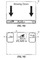
- illustrative speed change notifications are depicted comprising large arrows pointing up or down accompanied by the words "Speeding Up” or “Slowing Down,” respectively, to indicate a speed change event caused by the PCC system.
- display states 810 and 910 shown in FIGURES 8B and 9B other illustrative speed change notifications are depicted comprising a function tell-tale 162 that indicates an increase in speed and a decrease in speed, respectively.
- the display states 800, 810, 900, and 910 occur when PCC State is Fully Active and PCC Set Speed is greater than or less than Vehicle Speed, respectively.
- FIGURES 8A, 8B , 9A, and 9B omit some information shown in other examples described herein (e.g., FIGURES 10 and 11 ), which can help to remove visual noise and clarify the communication of the change in vehicle speed.
- additional information e.g., terrain information
- Either approach can be desirable, depending on the context of the communication.
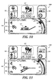
- An operator notification also can be used to indicate upcoming terrain features that may affect the vehicle speed set by the PCC system. For example, in the display states 1000, 1100, and 1700 shown in FIGURES 10, 11 , and 17 , respectively, the function tell-tale 162 and the speedometer graphic 350 have been updated to indicate that the PCC system is causing the truck to speed up ( FIGURES 10 and 17 ) or slow down ( FIGURE 11 ).
- the speedometer graphic 350 has been updated to indicate that the truck is speeding up from 55 mph.
- the slope diagram 330 has been updated to indicate an upcoming hill climb.
- the slope diagram 330 has been updated to indicate the upcoming end of a descent.
- the speedometer graphic 350 has been updated to indicate that the truck is slowing down from 55 mph, and the slope diagram 330 has been updated to indicate that a current hill climb is ending soon, thereby providing feedback to the truck operator to indicate why the truck is slowing down.
- the display states 1000, 1100, and 1700 shown in FIGURES 10, 11 , and 17 respectively, provide feedback to the truck operator to indicate both a change in speed caused by the PCC system and a reason why the change is occurring.
- An operator notification also can be used to indicate upcoming terrain features that are being monitored by the PCC system even if the vehicle speed will not be affected by the PCC system.
- the function tell-tale 162 and the speedometer graphic 350 indicate that no speed change will take place in view of current and/or upcoming terrain features.
- the display states shown in FIGURES 12-16 provide feedback to the truck operator to indicate both a steady speed and reasons (e.g., depictions of current and future terrain features that are being monitored by the PCC system) why no change is occurring.
- the slope diagram 330 depicts an upcoming downhill slope in FIGURE 12 , an ongoing hill climb in FIGURE 13 , an upcoming hill apex in FIGURE 14 , an upcoming valley in FIGURE 15 , and an ongoing descent in FIGURE 16 .
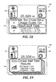
- Display state 2000 may also be presented when the vehicle is in motion.
- the function-specific view 164 includes features of a PCC system setup utility with functionality for adjusting user settings and performing system diagnostics via a "System Self Test" function.
- results of the self-test are displayed. As shown, the display state 1900 includes a message that indicates that the GPS signal test failed, which means that PCC functionality may not be available.
- the display state 2000 in FIGURE 20 may be used in the event of the PCC system fault detected in FIGURE 20 , or some other fault.
- the truck operator is advised to "maintain speed and braking manually" to manage vehicle speed in the absence of active PCC functionality.
- the display state 2000 can be presented when the truck is in motion or when the truck is parked, and can be dismissed as desired by the operator in order to minimize visual clutter.
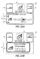
- the act of overruling the PCC system can be followed by a briefly displayed message (e.g., display state 2210 in FIGURE 22B ) to provide confirmation to the operator that the PCC system has been overruled.
- PCC Settings Change Indication also can indicate a change to the PCC Level, as described below.
- the feature that allows the operator to overrule operation of the PCC system can be enabled or disabled by an administrator, e.g., the vehicle owner.
- the amount of time that the operation of the PCC system has been overruled by the operator can be tracked (e.g., as a percentage of total driving time or of the time during which the base cruise control system is active) to determine, for example, whether additional coaching may be effective in increasing the amount of time that the operator allows the PCC system to remain active.
- FIGURES 23A , 24A , and 25A show display states 2300, 2400, and 2500 associated with different control bands for an active PCC system.
- one of three checkmarks is highlighted in the function-specific view 164 to indicate a first control band with a narrow speed adjustment range 2302 (e.g., from -3 mph to +0 mph).
- two checkmarks are highlighted in the function-specific view 164 to indicate a second control band with a wider speed adjustment range 2302 (e.g., from -5 mph to +3 mph).
- the darker-shaded bars 2304 in FIGURES 23A and 24A indicate an additional downhill speed offset that is available beyond the fueled positive offset provided by the PCC system for the given control band.
- the downhill speed offset can be omitted.
- a driver performance assistant (DPA) system exhibits functionality that encourages operator behavior to provide benefits such as improved performance and improved fuel economy.
- the DPA system can be adapted to work with one or more vehicle subsystems, including a PCC system.
- a DPA system can provide notifications to encourage the operator to activate a PCC system that has been deactivated (e.g., where events have been missed in which the PCC system would have adjusted the vehicle speed).
- the display state 2600 depicts an illustrative PCC activation reminder notification that includes a message (e.g., "Activating Eco-Cruise Saves Fuel") to encourage the operator to activate the PCC system.
- this display state appears for a brief time (e.g., 5 seconds) to avoid unnecessarily distracting the driver.
- the conditions under which the display state 2600 appears may vary depending on system settings, user preferences, and the like.
- the illustrative PCC activation reminder notification depicted in the display state 2600 may depend on the following parameters: Driver Coaching Setting, Event Missed Count, and Event In Range.
- Driver Coaching Setting indicates whether coaching messages (e.g., PCC coaching messages and/or other coaching messages) are enabled or not.
- Event Missed Count is incremented (e.g., by a value of 1) if a speed change event occurs in which the PCC system would have changed the target vehicle speed from the cruise control set speed, but was unable to do so because PCC system functionality was disabled. Such an event can be referred to as a missed event.
- Event In Range indicates that the PCC system is set to change the cruise control set speed in the near future.
- a DPA system can provide operator notifications to encourage the operator to select a wider control band if the PCC system would have adjusted the vehicle speed to a speed outside a narrower control band but within a wider control band.
- the display state 2700 includes an illustrative control band adjustment notification comprising a message (e.g., "Use a Wider Eco-Cruise Control Band to Save Fuel") to encourage the operator to user a wider control band (e.g., with a higher positive offset and/or a lower negative offset).
- the display state 2700 can be presented ahead of an upcoming speed change event in which the PCC system would adjust the vehicle speed to a speed outside the current, narrower control band but within a wider control band.
- Non-Optimal Event Count can be incremented (e.g., by a value of 1) if a speed change event occurs in which the PCC system would have adjusted the target vehicle speed from the set speed (e.g., by lowering it), but was unable to do so because the adjusted speed would be outside (e.g., lower than) a currently active control band.
- a speed change event occurs in which the PCC system would have adjusted the target vehicle speed from the set speed (e.g., by lowering it), but was unable to do so because the adjusted speed would be outside (e.g., lower than) a currently active control band.
- Such an event can be referred to as a Non-Optimal Event.
- Non-Optimal Event In Range indicates that the PCC system is set to adjust the target vehicle speed from the set speed to a speed outside (e.g., lower than) a currently active control band in the near future.
- an additional parameter e.g., Enable PCC Reminder
- an additional parameter can be used to indicate whether or not feedback (e.g., reminders) related to the PCC system are to be displayed.
- feedback e.g., reminders
- Some parameters e.g., Event Missed Count, Non-Optimal Event Count
- may be reset e.g., to a default value such as 0 if the DPA system is reset, which can prevent reminders relating to such parameters from occurring too frequently.
- control logic described in this section can be implemented in a variety of hardware, software, and combined hardware/software configurations (e.g., in an ECU such as the PCC ECU 120 depicted in FIGURES 1 and 2 ). Although illustrative details are provided in this section, it should be understood that alternative control logic and associated methods can be implemented and used in accordance with the present disclosure.
- a PCC driver control integration module 2810 receives the operator input signals PCC_Change_Level_Rq (to indicate a request for a change in the PCC level) and CC_Operator_Rq (to indicate a request for a change in the cruise control status (CC_State)).
- the PCC driver control integration module 2810 also receives the system parameters PCC_ENABLED_SPP (to indicate whether the PCC system is enabled) and PCC_DRIVER_OVERRIDE_ENABLED_SPP (to indicate whether the operator can override the function of an enabled PCC system).
- the module 2810 calculates a PCC level (PCC_Level) based on these signals.
- the module 2810 also outputs signals (b_PCC_Overruled_ByDriver, b_CC_Active, b_PCC_Settingsindication_Rq) to indicate possible updates in the PCC system that may result from the processing of the operator input and the PCC system parameters in the module 2810.
- DSC is enabled (as indicated by DSC_ENABLED_SPP) whenever the PCC system is enabled (as indicated by PCC_ENABLED_SPP).
- the PCC_Level signal is provided along with the cruise control set speed signal (CC_SetSpeed) to a speed margin module 2820.
- the speed margin module 2820 calculates and outputs speed margin signals (e.g., PCC_UpperSpdMargin, PCC_LowerSpdMargin, and PCC_SpeedMargins), and different upper and lower speed margins may be calculated for each PCC level (e.g., PCC_Level1_UpperSpdMargin, etc.).
- margins are calculated by multiplying CC_SetSpeed by a value associated with the margin for a particular PCC level, thereby allowing the margins to be proportional to the cruise control set speed. This can avoid potential drawbacks of static, narrow control bands that reduce the available fuel economy and drivability gains that may be available in wider control bands. Illustrative speed margin calculation values are shown in Table 1, below.
- Table 1 Values for calculating upper and lower speed margins PCC Level Speed Margin Value Offset from 60 mph Cruise Set Speed 0 Upper 0 0 mph Lower 0 0 mph 1 Upper 0 0 mph Lower -0.05 -3.0 mph 2 Upper 0.04 +2.4 mph Lower -0.07 -4.2 mph 3 Upper 0.08 +4.8 mph Lower -0.12 -7.2 mph
- the driver rewards arbitration module 2830 takes CC_SetSpeed and PCC_UpperSpdMargin as input and, when a change in CC_SetSpeed is detected, determines whether any changes should be made to PCC_UpperSpdMargin in view of driver rewards settings.
- the maximum driver rewards positive offset is calculated in the maximum driver rewards offset module 2910 based on the following input signals: Driver_Reward_Speed_Offset (the offset that is actually applied within the driver reward functionality; see Vehicle Speed Offset above), DRIVERREWARD_MAXIMUM_VEHICLE_SPEED_BONUS_SPP (the maximum vehicle speed offset within the driver reward functionality; see Vehicle Speed Bonus above), PCC_MAXIMIZE_FUEL_ECONOMY_SPP (indicating whether the PCC system is biased in favor of fuel economy), CC_MAX_SETSPEED_SPP (the maximum pedal speed plus any base cruise control offset speed; see V MAX and V CC OFFSET , above), and CC_Set_Speed.
- Driver_Reward_Speed_Offset the offset that is actually applied within the driver reward functionality; see Vehicle Speed Offset above
- DRIVERREWARD_MAXIMUM_VEHICLE_SPEED_BONUS_SPP the maximum vehicle speed offset within the driver reward functionality; see Vehicle Speed Bonus above
- the Maximum Driver Rewards Positive Offset is Driver_Reward_Speed_Offset + CC_MAX_SETSPEED_SPP - CC_SetSpeed; otherwise, it is set to be CC_MAX_SETSPEED_SPP + DRIVERREWARD_MAXIMUM_VEHICLE_SPEED_BONUS_SPP - CC_SetSpeed.
- FIGURE 31 is a flow diagram of an illustrative method 3100 that may be performed by the on-board vehicle computer system 100 described above, or by some other system that includes a PCC system, in accordance with aspects of the present disclosure.
- the system determines a new PCC set speed for a vehicle.
- the system detects that the PCC system has been disabled (e.g., by an operator of the vehicle).
- the system presents a PCC activation reminder notification (e.g., to remind the vehicle operator to activate the disabled PCC system).
- FIGURE 32 is a flow diagram of another illustrative method 3200 that may be performed by the on-board vehicle computer system 100 described above, or by some other system that includes a PCC system, in accordance with aspects of the present disclosure.
- the system determines a new PCC set speed for a vehicle.
- the system compares the new PCC set speed with a current control band.
- the system presents a control band adjustment notification (e.g., to remind the vehicle operator to select a wider control band).
- FIGURE 33 is a flow diagram of a detailed method 3300 that combines aspects of the methods 3100 and 3200 described above, along with additional aspects.
- the method may be performed by the on-board vehicle computer system 100 described above, or by some other system that includes a PCC system, in accordance with aspects of the present disclosure.
- the PCC system is initiated as the key is cycled (step 3302), driver notification settings revert to customer settings (step 3304), the PCC system is activated (step 3306), and the control band is set to a minimum active level (e.g., PCC Level 0, with a zero positive offset).
- a minimum active level e.g., PCC Level 0, with a zero positive offset.
- a new PCC set speed is calculated.
- a missed event count is compared with a threshold (step 3330).
- the missed event count is incremented if the threshold has not been reached. Otherwise, a missed event reminder count is incremented at step 3334.
- the missed event count is reset, and if reminders have not been disabled (step 3338), a reminder to activate the PCC system is provided at step 3340.
- the reminder counts can be used, for example, to ensure that a driver does not receive too many reminders to reactivate the PCC system or to use a wider control band.
- Processing stages in the various methods can be separated into additional stages or combined into fewer stages. Processing stages in the various methods also can be omitted or supplemented with other methods or processing stages. Furthermore, processing stages that are described as occurring in a particular order can instead occur in a different order and/or in a parallel fashion, with multiple components or software processes concurrently handling one or more of the illustrated processing stages. As another example, processing stages that are indicated as being performed by a particular device or module may instead be performed by one or more other devices or modules.
- notifications described herein can be omitted, supplemented with additional notifications, or replaced with different notifications or effects.
- visual elements described herein can be omitted, supplemented with additional elements, or replaced with different elements to provide, for example, different granularity of reminders (e.g., by making reminders more abrupt or more gradual, as may be desired in different situations).
Abstract
Description
- Predictive cruise control (PCC) systems are enhancements to traditional cruise control systems that set a target speed to be maintained by a vehicle in motion while the cruise control functionality is active. PCC systems automatically adjust cruise control target speeds based on a variety of inputs, such as a vehicle's position relative to a location on a route map, terrain or slope information, and predicted or predetermined paths to a destination. PCC systems, when properly used, can improve the fuel efficiency of a vehicle compared with traditional cruise control systems. Prior PCC systems have typically provided very little information to the operator of the vehicle, even to the extent of providing no signal to the operator that a PCC system is even active. Therefore, prior PCC systems may be undesirable for some operators, especially those having less experience with PCC systems.
- This summary is provided to introduce a selection of concepts in a simplified form that are further described below in the Detailed Description. This summary is not intended to identify key features of the claimed subject matter, nor is it intended to be used as an aid in determining the scope of the claimed subject matter.
- In some aspects, an on-board vehicle computer system for a vehicle includes at least one processing unit and a memory having stored therein computer-executable instructions configured to cause the on-board vehicle computer system to implement various aspects of a predictive cruise control (PCC) system. In one aspect, the computer system provides a plurality of available speed control bands in a PCC system, and the available speed control bands are selectable by an operator of the vehicle. Operator notifications associated with the PCC system may be presented via an operator interface (e.g., a touchscreen display provided in a vehicle dashboard or other easily accessible area). Presentation of the operator notifications may be based at least in part on a count of PCC speed change events, such as a count of events missed due to deactivation of the PCC system. Presentation of the operator notifications also may be based at least in part on a reminder setting, which may be adjustable by the operator of the vehicle. The operator notifications may include a speed control band adjustment notification that indicates a proposed change from a currently active speed control band to another of the available speed control bands. Presentation of the speed control band adjustment notification may be based on, for example, a speed change event in which a new PCC set speed is outside the currently active speed control band, or a count of speed change events in which PCC set speeds are outside the currently active speed control band.
- In another aspect, the computer system provides an upper speed margin and a lower speed margin for a PCC system, and the upper and lower speed margins are adjustable by an operator of the vehicle. The upper and lower speed margins may be associated with a speed control band. The computer system may present an operator interface configured to allow adjustments of the upper and lower speed margins by the operator of the vehicle.
- In another aspect, the computer system determines a speed control band for the vehicle in a PCC system, wherein the speed control band comprises an upper speed margin and a lower speed margin. The computer system compares the upper speed margin with a driver rewards offset value and, based on the comparison, updates the upper speed margin for the speed control band. For example, if the driver rewards offset value is less than the upper speed margin, the updated upper speed margin is equal to the driver rewards offset value. The driver rewards offset value may be based at least in part on a current driver reward speed offset, a maximum vehicle speed bonus, or a fuel economy setting.
- In another aspect, the PCC system analyzes roadway slope information calculates a PCC set speed based at least in part on the roadway slope information and a currently active speed control band. The currently active speed control band is selected (e.g., by an operator of the vehicle) from a plurality of available speed control bands. The computer system may present an operator notification indicating an upcoming change in roadway slope based on the roadway slope information or an operator notification indicating an upcoming change in vehicle speed based on the calculated PCC set speed.
- In some aspects, reminder notifications are presented via an operator interface (e.g., a touchscreen display provided in a vehicle dashboard or other easily accessible area). In one aspect, an on-board vehicle computing system determines a new PCC set speed for the vehicle, detects that the PCC system is disabled (e.g., by the operator of the vehicle), and presents a PCC activation reminder notification via the operator interface. Presentation of the PCC activation reminder notification may be based at least in part on a reminder setting, which may be adjustable by the operator of the vehicle and/or a count of speed change events.
- In another aspect, the computing system determines a new PCC set speed for the vehicle, compares the new PCC set speed with a current speed control band, and, based on the comparison, presents a speed control band adjustment notification via the operator interface. Presentation of the speed control band adjustment notification may be based at least in part on a feedback setting, which may be adjustable by the operator of the vehicle. Presentation of the speed control band adjustment notification may also be based on a count of speed change events in which PCC set speeds are outside a currently active speed control band.
- The foregoing aspects and many of the attendant advantages will become more readily appreciated as the same become better understood by reference to the following detailed description, when taken in conjunction with the accompanying drawings, wherein:
-
FIGURES 1 and2 are schematic diagrams of an illustrative on-board vehicle computer system having a PCC system with advanced operator control and feedback functionality; -
FIGURE 3 is a table of illustrative signals depicted inFIGURE 1 ; -
FIGURES 4-27 are screen shots of illustrative operator notifications that may be generated by a display device of a computing system such as the on-board vehicle computer system ofFIGURE 1 ; -
FIGURES 28-30 are diagrams of illustrative control logic for a PCC system with advanced operator control and feedback cabilities; and -
FIGURES 31-33 are flow charts of illustrative methods that may be implemented by a computing system such as the on-board vehicle computer system ofFIGURE 1 . - The detailed description set forth below in connection with the appended drawings is an illustrative and non-limiting description of various embodiments of the disclosed subject matter. The following description proceeds with reference to examples of systems and methods suitable for use in vehicles, such as
Class 8 trucks. Although illustrative embodiments of the present disclosure will be described hereinafter with reference to trucks, it will be appreciated that aspects of the present disclosure have wide application, and therefore, may be suitable for use with many types of vehicles, such as passenger vehicles, buses, commercial vehicles, light and medium duty vehicles, etc. - It should be understood that various embodiments of the present disclosure include logic and operations performed by electronic components. These electronic components, which may be grouped in a single location or distributed over a wide area, generally include processors, memory, storage devices, display devices, input devices, etc. It will be appreciated by one skilled in the art that the logic described herein may be implemented in a variety of hardware, software, and combined hardware/software configurations, including but not limited to, analog circuitry, digital circuitry, processing units, and the like. In circumstances where the components are distributed, the components are accessible to each other via communication links. A controller area network bus (or CAN bus) can be used to communicate vehicle operating conditions, e.g., as specified by the Society of Automotive Engineers (SAE) J1939 standard.
- Components and modules described herein may be communicatively coupled by any suitable means, e.g., an internal communications network such as a vehicle bus that uses a controller area network (CAN) protocol, a local interconnect network (LIN) protocol, and/or the like. Those of ordinary skill in the art will recognize that the vehicle bus may be implemented using any number of different communication protocols such as, but not limited to, Society of Automotive Engineers ("SAE") J1587, SAE J1922, SAE J1939, SAE J1708, and combinations thereof. In other embodiments, components may be connected by other networking protocols, such as Ethernet, Bluetooth, TCP/IP, and/or the like. In still other embodiments, components may be directly connected to each other without the use of a vehicle bus, such as by direct wired connections between the components. Embodiments of the present disclosure may be implemented using other types of currently existing or yet-to-be-developed in-vehicle computer systems without departing from the scope of the claimed subject matter.
- In general, predictive cruise control (PCC) systems can automatically adjust a cruise control target speed based on a variety of inputs, such as a truck's position relative to a location on a route map, terrain or slope information, and predicted or predetermined paths to a destination. PCC systems, when properly used, can improve the fuel efficiency of a truck compared with traditional cruise control systems.
- In described embodiments, the operator of a vehicle (e.g., a heavy duty truck) is provided with the ability to control and receive information relevant to the behavior of a PCC system. The level of human-machine interaction (HMI) and information supplied to the operator is scalable based on factors such as an operator's selected preferences, and is provided in an intuitive manner so as to minimize operator distractions.
- Described embodiments allow customized experiences for operators with different preferences and levels of experience. For example, more experienced operators can reduce the amount of information presented to minimize distractions, and less experienced operators or experienced operators that prefer higher levels of feedback can increase the amount of information presented to enable operators to reap greater benefits from the PCC system.
- Described embodiments also provide operators with control features such as the ability to select from among several speed control bands with different positive and negative offsets. (For brevity, speed control bands are referred to herein simply as "control bands.") Although such offsets are referred to herein as "positive" or "negative" to reflect common scenarios in which such offsets are used to increase or decrease vehicle speed, positive and negative offsets may also be zero in some situations, and thus need not be strictly positive or negative values. For example, a control band with zero positive offset can be used as an initial control band when the PCC system is initiated, which can provide safety and compliance-related benefits while encouraging the operator to allow the PCC system to remain active whenever cruise control is active, and thus achieve the expected fuel economy improvement.
- Described embodiments also provide the ability to deactivate the PCC system temporarily. Operators can be notified when the PCC system is active and when it is not. If the PCC system is not active, the PCC system can provide feedback as to why it is not active. Described embodiments also provide the ability to receive reminders and coaching messages designed to encourage the operator to activate (or reactivate) the PCC system, select a wider control band, and the like, in order to improve fuel efficiency and the operator's driving experience.
- Described embodiments also provide a method for detecting events in which the PCC system will set a target vehicle speed outside of the current control band but within a wider control band, as well as the ability to provide a notice to the operator to choose a wider control band ahead of such events and thereby take advantage of fuel economy or drivability gains that may be provided by the PCC system.
- The frequency of operator notifications can be calibrated to avoid unnecessarily distracting or annoying the operator. Notifications also can be turned off, if needed (e.g., for the duration of a single key cycle). Notifications that may be missed (e.g., due to deactivation of the PCC system) can be tracked. For example, a count of missed speed change events can be used to determine whether to remind an operator to activate the PCC system.
- In described embodiments, the PCC system also can provide different types and amounts of information based on truck status. For example, the PCC system can provide more information or more interactive features (e.g., setup utilities, diagnostic utilities, etc.) when the truck is parked in order to take advantage of the operator's ability to pay more attention to the PCC system when the truck is not in motion. As another example, the PCC system can provide less information or less interactive features when the truck is in motion in order to reduce the risk of distracting the operator.
- Visual cues such as graphical speedometer indicators, diagrams, text, icons, and the like can be used to communicate truck status, PCC system status, suggested actions, and other information that can be used to encourage particular operator behavior, which may increase PCC system usage or enhance the benefits of the PCC system when it is in use. The PCC system can allow operator control of some features and settings (e.g., to reduce or increase PCC system feedback, to avoid exceeding posted speed limits, etc.) while also biasing the system towards more desirable outcomes such as better fuel economy (which can benefit an entire fleet) and away from outcomes such as faster drive times (which may only benefit an individual operator).
- Prior PCC systems have typically provided very little information to the operator, even to the extent of providing no signal to the operator that a PCC system is active. Such systems can be undesirable for operators, especially those having less experience with PCC systems. Such systems can be confusing for an operator that may notice changes in truck behavior without being notified that a PCC system is active. Prior systems can interfere with the operator's ability to understand whether or not the truck is providing the intended functionality and resultant savings that PCC systems can provide. Prior systems that provide no opportunity for the operator to control the maximum and minimum offsets from the cruise control set speed may require minimal interaction from the operator, but lack of feedback and operator control can lead the operator to deactivate predictive cruise control completely if the vehicle's speed deviates too much, or without warning, from the cruise control set point.
- Embodiments described herein provide advantages over prior systems. For example, if the operator is traveling at the speed limit to maintain traffic flow and drive cycle time, the operator may not want to exceed the speed limit for safety or legal reasons, but the operator may be willing to reduce speed on hills to save fuel. In described embodiments, the operator's ability to choose a control band with zero positive offset can encourage use of the PCC system while respecting the operator's desire to avoid an increase in speed and thus reducing the chance that the operator will decide to deactivate the PCC system. As another example, if the operator is traveling down a hill where the heavier weight of the truck tends to make downhill velocities faster, the operator may choose to reduce the cruise control's positive offset to maintain a safe distance from lower-weight traffic ahead that tends to travel at slower speeds.
- This section describes features of an illustrative PCC system within an on-board vehicle computer system. In the illustrative PCC system, information can be provided to a truck operator to provide feedback and guide operator behavior. Although illustrative details are provided in this section, it should be understood that alternative systems and methods can be implemented and used in accordance with the present disclosure.
-
FIGURE 1 illustrates one embodiment of avehicle computer system 100 with PCC functionality, according to various aspects of the present disclosure. Thesystem 100 includes electronic control units (ECUs) 110, 120, and 130 that monitor truck status, control PCC functionality, generate operator notifications, and the like. - The
ECUs ECUs - The
ECUs engine ECU 130 may be communicatively coupled to one or more sensors that measure vehicle speed, and this information can be used to set a value for the Vehicle Speed signal depicted inFIGURE 1 . As another example, thePCC ECU 120 may be communicatively coupled to one or more sensors that measure a current slope of the roadway on which the truck is traveling, and this information can be used to set a value for the Current Slope signal depicted inFIGURE 1 . - In the example shown in
FIGURE 1 , theECUs CAN bus 140. Illustrative signals are shown that can be transmitted and/or received by theECUs CAN bus 140 and can be used to implement PCC functionality within thesystem 100. For example, thedisplay ECU 110 can generate and/or process signals such as Enhanced Driver Feedback, Initiate Self Test, Lower Limit, Upper Limit, CC (Cruise Control) Set Speed, and Vehicle Mode; the predictivecruise control ECU 120 can generate and/or process signals such as PCC State, PCC Set Speed, Current Slope, and Future Slope; and theengine ECU 130 can generate and/or process signals such as Vehicle Speed and CC Set Speed. - The type and value range of the illustrative signals depicted in
FIGURE 1 are shown in table 200 inFIGURE 3 and described in further detail below. Illustrative uses of these signals and other signals are described in detail below. - In this example, PCC State describes whether the PCC system is active. If the PCC system is not active, PCC State also may include an indication of why the PCC system is not active. As shown in table 200, PCC State can be, for example, in a "Fully Active" state or in an inactive state that may be caused by any of several possible error conditions (e.g., truck position is unavailable, map location is unavailable, slope information is unavailable, predicted path is unavailable, or vehicle speed is too slow). CC Set Speed describes an operator-specified vehicle set speed for cruise control functionality, whereas PCC Set Speed describes a target vehicle speed set by the PCC system. In the example shown in
FIGURE 3 , these parameters are described, along with Vehicle Speed, as being continuously variable in a range of 0 to 128 mph, although in operation these parameters typically will be restricted to a smaller range (e.g., by a maximum pedal speed, a maximum or minimum cruise control set speed, etc.). - Current Slope and Future Slope can be used to describe current terrain and future terrain as being an upslope, a downslope, or flat. This information can be used to make adjustments to vehicle speed in the PCC system, as discussed in further detail below. Lower Limit and Upper Limit can be used to describe lower and upper speed margins in terms of negative offsets and positive offsets, respectively, for vehicle speed adjustments within the PCC system. In the example shown in
FIGURE 3 , Lower Limit and Upper Limit are described as being continuously variable in a range of -10 to 0 mph and 0 to 10 mph, respectively, although in practice these parameters may be restricted to a smaller range (e.g., based on user preferences or system settings), as described in detail below. - In the example shown in
FIGURE 3 , Enhanced Driver Feedback is defined as a Boolean value that is used to indicate whether additional driver feedback (e.g., in the form of operator notifications on a display) is desired, and Initiate Self Test is defined as a Boolean value that is used to indicate whether a PCC system self-test is to be initiated. Illustrative operator notifications and self-test utilities are described in detail below. - In the example shown in
FIGURE 1 , thedisplay ECU 110 communicates with anoperator interface 112 that includes anoperator display 102. Theoperator display 102 may be any type of display used in a truck to convey information to the operator. For example, theoperator display 102 may include an LCD display configured to display information to the operator much like any other computing display. In a touchscreen configuration, theoperator display 102 also has input capabilities. In addition to theoperator display 102, theoperator interface 112 also may include other output devices for visual output or other output, such as lamps, needle gauges, speakers, or haptic feedback devices, to provide information to the operator. Theoperator interface 112 also may include other input devices including buttons, toggles, keyboards, mechanical levers, and any other devices that allow an operator to provide input to thesystem 100. - In the example shown in
FIGURE 1 , two illustrative display states 1700 and 2100 are shown that can be presented on thedisplay 102. Thedisplay state 1700 is an example of a display state that may be in effect when the Vehicle Mode is "Driving." Thedisplay state 1700 includes a function tell-tale 162 with an icon to indicate that the truck is in an "Eco-Cruise" mode in which the PCC system is active. Thedisplay state 1700 also includes a function-specific view 164 that provides additional information related to the PCC system. Thedisplay state 2100 is an example of a display state that may be in effect when the Vehicle Mode is "Parked." Thedisplay state 2100 includes features of a PCC system setup utility. The features of the display states 1700 and 2100 and other illustrative display states are described in further detail below. - The
ECUs FIGURE 2 , the predictivecruise control ECU 120 is depicted as receiving signals from an advancedstability control module 170, an adaptivecruise control module 172, adriver reward module 174, a generalcruise control module 176, and anengine retarder module 178. - The adaptive
cruise control module 172 can provide a truck with the ability to detect objects in front of it and adjust vehicle speed to ensure proper spacing and reduce the possibility of collisions or the need for sudden braking. In at least one embodiment, if both ACC and PCC functionality are present, PCC functionality is not active unless ACC functionality is not in an error state. PCC also may be deactivated in response to other events related to vehicle status or operating conditions, such as a stability control event generated by the advancedstability control module 170. - In the example shown in
FIGURE 2 , illustrative input signals provided to thePCC ECU 120 include Cruise Control State, CC Set Speed, VMAX, and VCC OFFSET from thecruise control module 176; Driver Reward Active, Offset Mode, Vehicle Speed Offset, and Vehicle Speed Bonus from thedriver reward module 174, and VOFFSET, DSC from the engineretarder control module 178, and VSPEED. In the example shown inFIGURE 2 , the predictivecruise control ECU 120 takes these inputs (and potentially other inputs, as may be provided by an operator or from other input sources) to generate output signals, including PCC Set Speed. PCC Set Speed may be provided to other modules, such as a vehiclespeed limiter module 180 that may be communicatively coupled to a torquespeed control module 190. - In this example, Cruise Control State indicates the state of the base cruise control functionality. Possible values of this state variable include Off, On, Active/Resume, Cancel, and Overrule. VMAX describes the maximum vehicle speed that is available via the accelerator pedal, with no active offsets. VCC OFFSET describes the offset speed from VMAX that is applied when cruise control is active. VSPEED describes the current vehicle speed. Driver Reward Active indicates whether the driver reward system is active, which can be used to provide performance bonuses, such as added speed, to reward operators for desirable behaviors or results (e.g., achieving a target fuel economy value). Offset Mode indicates whether any driver reward offsets are applied to the pedal speed limit, the cruise control speed limit, or both. Vehicle Speed Bonus describes the maximum vehicle speed offset within the driver reward functionality, and Vehicle Speed Offset describes the offset that is actually applied within the driver reward functionality.
- VOFFSET,DSC describes an offset speed that defines a target speed for downhill speed control (DSC) module or other automatic engine retarding functionality. In at least one embodiment, DSC is enabled whenever the PCC system is enabled.
- In at least one embodiment, although parameters such as VMAX and Vehicle Speed Offset may vary (e.g., based on driver rewards functionality), the PCC Set Speed need not automatically change in response to such changes. For example, PCC Set Speed may remain the same if changes in parameters such as VMAX or Vehicle Speed Offset still result in a calculated PCC Set Speed that remains within the currently active control band.
- The
ECUs system 100, as described herein, to perform one or more of the functions described herein. Vehicle data may include data that is sensed and stored during vehicle operation, as well as programmable settings that can be programmed by the vehicle manufacturer, the owner, the operator, or any other suitable entity. - A variety of graphics, messages, and other output can be used to provide feedback to operators. Such feedback can be referred to as operator notifications. In a truck with a PCC system, operator notifications can be used to provide detailed information to operators that describe, for example, the status of the PCC system and suggestions for increasing the benefits of the PCC system. In any of the examples described herein, the content, appearance, or presence of operator notifications may depend on operator preferences, system settings, or other factors. It at least one embodiment, the appearance or presence of some operator notifications depends on the value of the Enhanced Driver Feedback variable described above. Example operator notifications are described in detail below.
- In examples described herein, operator notifications comprising visual elements are described. Depending on implementation, the visual elements can include graphics, text, icons, and the like. Depending on implementation, one or more visual elements may be activated (e.g., by touch in a touch-enabled interface) to access additional information or functionality. Operator notifications may be displayed for a defined period of time or until a particular event occurs. Notifications may be non-suppressible or suppressible. Non-suppressible notifications may not be dismissed until an underlying condition is satisfied, while suppressible notifications may be dismissed at an operator's discretion.
- The visual and functional elements described in the following examples can be replaced with any other elements that are suitable for communicating the information described in these examples. Further, the elements described in the following examples can be presented in different ways (e.g., in different colors, sizes, or display locations; animated or static; flashing or not flashing; flashing at different rates; with or without sound; movable (e.g., by an operator interacting with a touchscreen) or in a fixed location; etc.) to communicate the information described in these examples.
- Examples of PCC system operator notifications are now described with reference to
FIGURES 4-27 , which are screen shots depicting various display states in accordance with aspects of the present disclosure. Many of the display states include operator notifications comprising a function tell-tale 162 that indicates a basic status of the PCC system. Many of the display states also include operator notifications comprising a function-specific view 164 that provides more detailed information, if available, about the PCC system. Many of the display states also includehome screen information - In the
display state 300 shown inFIGURE 4 , the function tell-tale 162 indicates that the base cruise control system is active with cruise set speed of 55 mph. However, the function-specific view 164 includes a message that indicates that sufficient PCC system data is not available and that the truck will remain at the cruise set speed without PCC-generated speed adjustments. This message may be displayed, for example, when an operator attempts to activate the PCC system when PCC State is in an error condition, such as where vehicle position is unavailable, map location is unavailable, roadway slope information is unavailable, or a predicted path is unavailable. - In the
display state 400 shown inFIGURE 5A , the function tell-tale 162 indicates that the PCC system has been enabled (via the "ECO" symbol). The function-specific view 164 includes a speedometer graphic 350 that indicates the potential positive and negative speed offsets that are currently in effect within the PCC system. The function-specific view 164 also includes a slope diagram 330 that indicates the current slope and future slope of the roadway on which the truck is traveling, as well as additional icons such as aroad information icon 340, a driver rewardsicon 342, and acruise control icon 344. In at least one embodiment, thedisplay state 400 occurs when Vehicle Mode = Driving, PCC State = Fully Active, Current Slope = Flat, and Next Slope = Flat. InFIGURE 5B , the function tell-tale 162 in thedisplay state 500 provides another example of how the PCC system can indicate that the PCC Set Speed is equal to the cruise control set speed (e.g., as defined by the variable CC Set Speed), without displaying a function-specific view 164. - In the
display state 600 shown inFIGURE 6A , the function tell-tale 162 indicates that the base cruise control system is on, but it has not been updated to indicate that the PCC system is active. However, the function-specific view 164 includes a message that indicates the activation of the PCC system and that the truck may vary from the cruise set speed with PCC speed adjustments. To avoid unnecessary feedback as the PCC system is activated and deactivated during operation of the truck, in one implementation thedisplay state 600 occurs on the first occurrence of this transition since the last key-on event for the truck. As an alternative to thedisplay state 600, thedisplay state 610 shown inFIGURE 6B also indicates that the PCC system has been activated (with the text "Eco-Cruise: On") in an alternative arrangement within the function-specific view 164. The messages depicted in display states 600 and 610 may be displayed, for example, when Cruise Control State = ON and the PCC system is active (e.g., when PCC State transitions to a Fully Active state). - An operator notification also can be used to indicate a transition from an active state to an inactive state. In the
display state 700 shown inFIGURE 7A , a large PCC icon accompanied by the word "OFF" is used to indicate that the PCC system has transitioned to an inactive state. As an alternative to thedisplay state 700, thedisplay state 710 shown inFIGURE 7B also indicates that the PCC system has been deactivated, with the text "Eco-Cruise: Off' appearing in the function-specific view 164. - In an active PCC state, a display state can be used to indicate a speed change event that is attributed to the PCC system. In the display states 800 and 900 shown in
FIGURES 8A and9A , respectively, illustrative speed change notifications are depicted comprising large arrows pointing up or down accompanied by the words "Speeding Up" or "Slowing Down," respectively, to indicate a speed change event caused by the PCC system. In the display states 810 and 910 shown inFIGURES 8B and9B , other illustrative speed change notifications are depicted comprising a function tell-tale 162 that indicates an increase in speed and a decrease in speed, respectively. In some embodiments, the display states 800, 810, 900, and 910 occur when PCC State is Fully Active and PCC Set Speed is greater than or less than Vehicle Speed, respectively. - The examples shown in
FIGURES 8A, 8B ,9A, and 9B omit some information shown in other examples described herein (e.g.,FIGURES 10 and 11 ), which can help to remove visual noise and clarify the communication of the change in vehicle speed. On the other hand, additional information (e.g., terrain information) may help the operator to better understand the behavior of the truck and the operation of the PCC system. Either approach can be desirable, depending on the context of the communication. - An operator notification also can be used to indicate upcoming terrain features that may affect the vehicle speed set by the PCC system. For example, in the display states 1000, 1100, and 1700 shown in
FIGURES 10, 11 , and17 , respectively, the function tell-tale 162 and the speedometer graphic 350 have been updated to indicate that the PCC system is causing the truck to speed up (FIGURES 10 and17 ) or slow down (FIGURE 11 ). - In the display states 1000 and 1700, the speedometer graphic 350 has been updated to indicate that the truck is speeding up from 55 mph. In the
display state 1000, the slope diagram 330 has been updated to indicate an upcoming hill climb. In at least one embodiment, thedisplay state 1000 occurs when Vehicle Mode = Driving, PCC State = Fully Active, Current Slope = Flat, and Next Slope = Up. In thedisplay state 1700, the slope diagram 330 has been updated to indicate the upcoming end of a descent. In at least one embodiment, thedisplay state 1700 occurs when Vehicle Mode = Driving, PCC State = Fully Active, Current Slope = Down, and Next Slope = Flat. - In the
display state 1100, the speedometer graphic 350 has been updated to indicate that the truck is slowing down from 55 mph, and the slope diagram 330 has been updated to indicate that a current hill climb is ending soon, thereby providing feedback to the truck operator to indicate why the truck is slowing down. In at least one embodiment, thedisplay state 1100 occurs when Vehicle Mode = Driving, PCC State = Fully Active, Current Slope = Up, and Next Slope = Flat. The display states 1000, 1100, and 1700 shown inFIGURES 10, 11 , and17 , respectively, provide feedback to the truck operator to indicate both a change in speed caused by the PCC system and a reason why the change is occurring. - An operator notification also can be used to indicate upcoming terrain features that are being monitored by the PCC system even if the vehicle speed will not be affected by the PCC system. For example, in the display states 1200, 1300, 1400, 1500, and 1600 shown in
FIGURES 12-16 , respectively, the function tell-tale 162 and the speedometer graphic 350 indicate that no speed change will take place in view of current and/or upcoming terrain features. The display states shown inFIGURES 12-16 provide feedback to the truck operator to indicate both a steady speed and reasons (e.g., depictions of current and future terrain features that are being monitored by the PCC system) why no change is occurring. - The slope diagram 330 depicts an upcoming downhill slope in
FIGURE 12 , an ongoing hill climb inFIGURE 13 , an upcoming hill apex inFIGURE 14 , an upcoming valley inFIGURE 15 , and an ongoing descent inFIGURE 16 . In at least one embodiment, the display states 1200, 1300, 1400, 1500, and 1600 occur when Vehicle Mode = Driving, PCC State = Fully Active, and the following conditions apply: Current Slope = Flat and Next Slope = Down (FIGURE 12 ); Current Slope and Next Slope = Up (FIGURE 13 ); Current Slope = Up and Next Slope = Down (FIGURE 14 ); Current Slope = Down and Next Slope = Up (FIGURE 15 ); and Current Slope and Next Slope = Down (FIGURE 16 ). -
FIGURES 18-21 depict display states 1800, 1900, 2000, and 2100, respectively, that may be presented when the vehicle is parked (e.g., as indicated by Vehicle Mode = Parked) in at least one implementation. (Display state 2000 may also be presented when the vehicle is in motion.) In the display states 1800 and 2000, the function-specific view 164 includes features of a PCC system setup utility with functionality for adjusting user settings and performing system diagnostics via a "System Self Test" function. Indisplay state 1800, the "Start Self Test" function is selected, as indicated by the rounded rectangle in the function-specific view 164, which also includes additional PCC system information such as a lower speed adjustment limit ("Lower Limit = -5 mph"), an upper speed adjustment limit ("Upper Limit = +3 mph"), and a maximum downhill speed ("Max Downhill = 67 mph"). Indisplay state 1900, results of the self-test are displayed. As shown, thedisplay state 1900 includes a message that indicates that the GPS signal test failed, which means that PCC functionality may not be available. Thedisplay state 2000 inFIGURE 20 may be used in the event of the PCC system fault detected inFIGURE 20 , or some other fault. As shown inFIGURE 20 , the truck operator is advised to "maintain speed and braking manually" to manage vehicle speed in the absence of active PCC functionality. Thedisplay state 2000 can be presented when the truck is in motion or when the truck is parked, and can be dismissed as desired by the operator in order to minimize visual clutter. - In the example shown in
FIGURE 21 , the Usage Cues settings function is selected, indicating that Usage Cues are currently on. In at least one implementation, this setting means that Enhanced Driver Feedback = True. Additional settings shown inFIGURE 21 , such as the Lower Limit and Upper Limit, can be similarly selected and adjusted, as desired. In some implementations, settings such as the Lower Limit, Upper Limit, Maximum Downhill Speed, and other settings may be constrained or fixed. - In some embodiments, if the PCC system is active, it may be in one of several possible control bands with a range of available vehicle speed adjustments, including an upper limit and a lower limit. The variable PCC Level can be used to indicate whether the PCC system is active, and if so, the current control band. In at least one embodiment, PCC Level can be set at 0, 1, 2, or 3. Overruling the PCC system or deactivating the PCC system sets PCC Level = 0. The
display state 2200 shown inFIGURE 22A includes the message "Eco-Cruise: Overruled" in the function-specific view 164 to indicate that the PCC system has been overruled by the operator (PCC Overruled By Driver = True), while the function tell-tale 162 indicates that the base cruise control remains active with a cruise set speed of 60 mph. - The act of overruling the PCC system can be followed by a briefly displayed message (e.g.,
display state 2210 inFIGURE 22B ) to provide confirmation to the operator that the PCC system has been overruled. In at least one embodiment, thedisplay state 2210 is not presented unless the variable PCC Settings Change Indication = True, indicating that a successful request has been made to overrule the PCC system. PCC Settings Change Indication also can indicate a change to the PCC Level, as described below. - In at least one embodiment, the feature that allows the operator to overrule operation of the PCC system can be enabled or disabled by an administrator, e.g., the vehicle owner. In addition, the amount of time that the operation of the PCC system has been overruled by the operator can be tracked (e.g., as a percentage of total driving time or of the time during which the base cruise control system is active) to determine, for example, whether additional coaching may be effective in increasing the amount of time that the operator allows the PCC system to remain active.
-
FIGURES 23A ,24A , and25A show display states 2300, 2400, and 2500 associated with different control bands for an active PCC system. In the example shown in display state 2300 (PCC Level = 1), one of three checkmarks is highlighted in the function-specific view 164 to indicate a first control band with a narrow speed adjustment range 2302 (e.g., from -3 mph to +0 mph). In the example shown in display state 2400 (PCC Level = 2), two checkmarks are highlighted in the function-specific view 164 to indicate a second control band with a wider speed adjustment range 2302 (e.g., from -5 mph to +3 mph). The darker-shadedbars 2304 inFIGURES 23A and24A indicate an additional downhill speed offset that is available beyond the fueled positive offset provided by the PCC system for the given control band. Alternatively, the downhill speed offset can be omitted. - In the example shown in display state 2500 (PCC Level = 3), three checkmarks are highlighted in the function-
specific view 164 to indicate a third control band with a still-wider speed adjustment range 2302 (e.g., from -10 mph to +10 mph). The act of transitioning to a specific control band can be followed by a briefly displayed message (e.g., display states 2310, 2410, and 2510 inFIGURES 23B ,24B , and25B , respectively) to provide confirmation to the operator that a selected control band is now active. In at least one embodiment, the display states 2310, 2410, and 2510 are not presented unless the variable PCC Settings Change Indication = True, indicating that a successful request has been made to change the PCC Level. - In some embodiments, a driver performance assistant (DPA) system exhibits functionality that encourages operator behavior to provide benefits such as improved performance and improved fuel economy. The DPA system can be adapted to work with one or more vehicle subsystems, including a PCC system.
- For example, a DPA system can provide notifications to encourage the operator to activate a PCC system that has been deactivated (e.g., where events have been missed in which the PCC system would have adjusted the vehicle speed). In the example shown in
FIGURE 26 , thedisplay state 2600 depicts an illustrative PCC activation reminder notification that includes a message (e.g., "Activating Eco-Cruise Saves Fuel") to encourage the operator to activate the PCC system. In at least one embodiment, this display state appears for a brief time (e.g., 5 seconds) to avoid unnecessarily distracting the driver. The conditions under which thedisplay state 2600 appears may vary depending on system settings, user preferences, and the like. - In some embodiments, the illustrative PCC activation reminder notification depicted in the
display state 2600 may depend on the following parameters: Driver Coaching Setting, Event Missed Count, and Event In Range. Driver Coaching Setting indicates whether coaching messages (e.g., PCC coaching messages and/or other coaching messages) are enabled or not. Event Missed Count is incremented (e.g., by a value of 1) if a speed change event occurs in which the PCC system would have changed the target vehicle speed from the cruise control set speed, but was unable to do so because PCC system functionality was disabled. Such an event can be referred to as a missed event. Event In Range indicates that the PCC system is set to change the cruise control set speed in the near future. In at least one embodiment, thedisplay state 2600 is presented if Driver Coaching Setting is "enabled," Event Missed Count is greater than or equal to a threshold number (which may be customized), and Event In Range = True. - As another example, a DPA system can provide operator notifications to encourage the operator to select a wider control band if the PCC system would have adjusted the vehicle speed to a speed outside a narrower control band but within a wider control band. In the example shown in
FIGURE 27 , thedisplay state 2700 includes an illustrative control band adjustment notification comprising a message (e.g., "Use a Wider Eco-Cruise Control Band to Save Fuel") to encourage the operator to user a wider control band (e.g., with a higher positive offset and/or a lower negative offset). In at least one embodiment, thedisplay state 2700 can be presented ahead of an upcoming speed change event in which the PCC system would adjust the vehicle speed to a speed outside the current, narrower control band but within a wider control band. - The control band adjustment notification depicted in the
display state 2700 may depend on the following parameters: Non-Optimal Event Count and Non-Optimal Event In Range. For example, Non-Optimal Event Count can be incremented (e.g., by a value of 1) if a speed change event occurs in which the PCC system would have adjusted the target vehicle speed from the set speed (e.g., by lowering it), but was unable to do so because the adjusted speed would be outside (e.g., lower than) a currently active control band. Such an event can be referred to as a Non-Optimal Event. Non-Optimal Event In Range indicates that the PCC system is set to adjust the target vehicle speed from the set speed to a speed outside (e.g., lower than) a currently active control band in the near future. In this example, thedisplay state 2600 can be presented if Non-Optimal Event Count is greater than or equal to a threshold number (which may be customized), and Non-Optimal Event In Range = True. - To provide an additional level of control over PCC messages in a DPA system, an additional parameter (e.g., EnablePCC Reminder) can be used to indicate whether or not feedback (e.g., reminders) related to the PCC system are to be displayed. In this way, coaching messages can be generally enabled within the DPA system, while still allowing the ability to turn PCC system feedback messages on or off. Some parameters (e.g., Event Missed Count, Non-Optimal Event Count) may be reset (e.g., to a default value such as 0) if the DPA system is reset, which can prevent reminders relating to such parameters from occurring too frequently.
- In this section, illustrative control logic for a PCC system with advanced operator control and feedback cabilities is described. The control logic described in this section can be implemented in a variety of hardware, software, and combined hardware/software configurations (e.g., in an ECU such as the
PCC ECU 120 depicted inFIGURES 1 and2 ). Although illustrative details are provided in this section, it should be understood that alternative control logic and associated methods can be implemented and used in accordance with the present disclosure. - In the example shown in
FIGURE 28 , a PCC drivercontrol integration module 2810 receives the operator input signals PCC_Change_Level_Rq (to indicate a request for a change in the PCC level) and CC_Operator_Rq (to indicate a request for a change in the cruise control status (CC_State)). The PCC drivercontrol integration module 2810 also receives the system parameters PCC_ENABLED_SPP (to indicate whether the PCC system is enabled) and PCC_DRIVER_OVERRIDE_ENABLED_SPP (to indicate whether the operator can override the function of an enabled PCC system). Themodule 2810 calculates a PCC level (PCC_Level) based on these signals. Themodule 2810 also outputs signals (b_PCC_Overruled_ByDriver, b_CC_Active, b_PCC_Settingsindication_Rq) to indicate possible updates in the PCC system that may result from the processing of the operator input and the PCC system parameters in themodule 2810. In addition, in this example, DSC is enabled (as indicated by DSC_ENABLED_SPP) whenever the PCC system is enabled (as indicated by PCC_ENABLED_SPP). - In the example shown in
FIGURE 28 , the PCC_Level signal is provided along with the cruise control set speed signal (CC_SetSpeed) to aspeed margin module 2820. In this example, for PCC levels of 1, 2, or 3, thespeed margin module 2820 calculates and outputs speed margin signals (e.g., PCC_UpperSpdMargin, PCC_LowerSpdMargin, and PCC_SpeedMargins), and different upper and lower speed margins may be calculated for each PCC level (e.g., PCC_Level1_UpperSpdMargin, etc.). These margins are calculated by multiplying CC_SetSpeed by a value associated with the margin for a particular PCC level, thereby allowing the margins to be proportional to the cruise control set speed. This can avoid potential drawbacks of static, narrow control bands that reduce the available fuel economy and drivability gains that may be available in wider control bands. Illustrative speed margin calculation values are shown in Table 1, below.Table 1: Values for calculating upper and lower speed margins PCC Level Speed Margin Value Offset from 60 mph Cruise Set Speed 0 Upper 0 0 mph Lower 0 0 mph 1 Upper 0 0 mph Lower -0.05 -3.0 mph 2 Upper 0.04 +2.4 mph Lower -0.07 -4.2 mph 3 Upper 0.08 +4.8 mph Lower -0.12 -7.2 mph - The values shown in Table 1, above, are only examples and may be replaced with other values or applied to different cruise set speeds to achieve different offsets.
- In the example shown in
FIGURE 28 , the driver rewardsarbitration module 2830 takes CC_SetSpeed and PCC_UpperSpdMargin as input and, when a change in CC_SetSpeed is detected, determines whether any changes should be made to PCC_UpperSpdMargin in view of driver rewards settings. In the illustrative driver rewardsarbitration module 2830 shown inFIGURE 29 , if the driver reward system is active (DriverReward_Active = True) and the driver reward is applied to the cruise control speed limit (e.g., if DRIVERREWARD_OFFSET_MODE_SPP is greater than or equal to 2), then the output of themodule 2830 is set to be the PCC_UpperSpeedMargin or a maximum driver rewards positive offset, whichever is less. The maximum driver rewards positive offset is calculated in the maximum driver rewards offsetmodule 2910 based on the following input signals: Driver_Reward_Speed_Offset (the offset that is actually applied within the driver reward functionality; see Vehicle Speed Offset above), DRIVERREWARD_MAXIMUM_VEHICLE_SPEED_BONUS_SPP (the maximum vehicle speed offset within the driver reward functionality; see Vehicle Speed Bonus above), PCC_MAXIMIZE_FUEL_ECONOMY_SPP (indicating whether the PCC system is biased in favor of fuel economy), CC_MAX_SETSPEED_SPP (the maximum pedal speed plus any base cruise control offset speed; see VMAX and VCC OFFSET, above), and CC_Set_Speed. - In the
illustrative module 2910 shown inFIGURE 30 , if PCC_MAXIMIZE_FUEL_ECONOMY_SPP = True, then the Maximum Driver Rewards Positive Offset is Driver_Reward_Speed_Offset + CC_MAX_SETSPEED_SPP - CC_SetSpeed; otherwise, it is set to be CC_MAX_SETSPEED_SPP + DRIVERREWARD_MAXIMUM_VEHICLE_SPEED_BONUS_SPP - CC_SetSpeed. - For more information on illustrative driver rewards systems that may be used in combination with embodiments described herein, see co-pending
U.S. Patent Application No. 14/020,638 , entitled "Real-Time Driver Reward Display System and Method," filed on September 6, 2013, which is incorporated herein by reference. - In this section, illustrative methods for a PCC system with advanced operator control and feedback cabilities are described. The methods described in this section can be performed by a variety of hardware, software, and combined hardware/software configurations (e.g., in an ECU such as the
PCC ECU 120 depicted inFIGURES 1 and2 ). Although illustrative details are provided in this section, it should be understood that alternative methods can be implemented and used in accordance with the present disclosure. -
FIGURE 31 is a flow diagram of anillustrative method 3100 that may be performed by the on-boardvehicle computer system 100 described above, or by some other system that includes a PCC system, in accordance with aspects of the present disclosure. Atstep 3110, the system determines a new PCC set speed for a vehicle. Atstep 3120, the system detects that the PCC system has been disabled (e.g., by an operator of the vehicle). Atstep 3130, the system presents a PCC activation reminder notification (e.g., to remind the vehicle operator to activate the disabled PCC system). -
FIGURE 32 is a flow diagram of anotherillustrative method 3200 that may be performed by the on-boardvehicle computer system 100 described above, or by some other system that includes a PCC system, in accordance with aspects of the present disclosure. Atstep 3210, the system determines a new PCC set speed for a vehicle. Atstep 3220, the system compares the new PCC set speed with a current control band. Atstep 3230, the system presents a control band adjustment notification (e.g., to remind the vehicle operator to select a wider control band). -
FIGURE 33 is a flow diagram of adetailed method 3300 that combines aspects of themethods vehicle computer system 100 described above, or by some other system that includes a PCC system, in accordance with aspects of the present disclosure. Atsteps PCC Level 0, with a zero positive offset). Atstep 3310, a new PCC set speed is calculated. If the PCC system has been deactivated by the driver but the cruise control system is still active (step 3320), a missed event count is compared with a threshold (step 3330). Atstep 3332, the missed event count is incremented if the threshold has not been reached. Otherwise, a missed event reminder count is incremented atstep 3334. Atstep 3336, the missed event count is reset, and if reminders have not been disabled (step 3338), a reminder to activate the PCC system is provided atstep 3340. - If the PCC system has not been deactivated, a determination is made at
step 3350 as to whether the new PCC set speed is outside the current control band. If it is not, the vehicle speed is adjusted to the new PCC set speed atstep 3360. If it is, a non-optimal event count is compared with a threshold (step 3370). Atstep 3372, the non-optimal event count is incremented if the threshold has not been reached. Otherwise, a non-optimal event reminder count is incremented atstep 3374. Atstep 3376, the non-optimal event count is reset, and if reminders have not been disabled (step 3378), a reminder to use a wider control band is provided atstep 3380. - The reminder counts can be used, for example, to ensure that a driver does not receive too many reminders to reactivate the PCC system or to use a wider control band.
- The particular signals, variables, and parameters described herein, as well as their respective possible ranges and states and the particular logic for processing them, are not required. Depending on implementation, more or fewer or different signals, variables, and parameters may be used to achieve similar results. In any of the examples described herein, the specific signals, variables, and parameters that are described can be separated into additional signals, variables, or parameters, or combined into fewer signals, variables, or parameters.
- Many alternatives to the described methods are possible. Processing stages in the various methods can be separated into additional stages or combined into fewer stages. Processing stages in the various methods also can be omitted or supplemented with other methods or processing stages. Furthermore, processing stages that are described as occurring in a particular order can instead occur in a different order and/or in a parallel fashion, with multiple components or software processes concurrently handling one or more of the illustrated processing stages. As another example, processing stages that are indicated as being performed by a particular device or module may instead be performed by one or more other devices or modules.
- Many alternatives to the set of operator notifications described herein are possible. For example, notifications described herein can be omitted, supplemented with additional notifications, or replaced with different notifications or effects. As another example, visual elements described herein can be omitted, supplemented with additional elements, or replaced with different elements to provide, for example, different granularity of reminders (e.g., by making reminders more abrupt or more gradual, as may be desired in different situations).
- The principles, representative embodiments, and modes of operation of the present disclosure have been described in the foregoing description. However, aspects of the present disclosure which are intended to be protected are not to be construed as limited to the particular embodiments disclosed. Further, the embodiments described herein are to be regarded as illustrative rather than restrictive. It will be appreciated that variations and changes may be made by others, and equivalents employed, without departing from the spirit of the present disclosure. Accordingly, it is expressly intended that all such variations, changes, and equivalents fall within the spirit and scope of the claimed subject matter.
Claims (15)
- The embodiments of the invention in which an exclusive property or privilege is claimed are defined as follows:1. A computer-implemented method comprising:by an on-board vehicle computing system of a vehicle, determining a new predictive cruise control set speed for the vehicle in a predictive cruise control system;by the on-board vehicle computing system, comparing the new predictive cruise control set speed with a current speed control band that is adjustable by an operator of the vehicle; andbased on the comparing, presenting a speed control band adjustment notification via an operator interface of the vehicle.
- The computer-implemented method of Claim 1, wherein presenting the speed control band adjustment notification is based at least in part on a feedback setting.
- The computer-implemented method of Claim 2, wherein the feedback setting is adjustable by the operator of the vehicle.
- The computer-implemented method of any of Claims 1-3, wherein presenting the speed control band adjustment notification is based at least in part on a count of speed change events in which predictive cruise control set speeds are outside a currently active speed control band.
- The computer-implemented method of any of Claims 1-4, wherein the operator interface comprises a touchscreen display.
- The computer-implemented method of any of Claims 1-5, wherein a plurality of available speed control bands are provided in the predictive cruise control system, and wherein the available speed control bands are selectable by the operator of the vehicle.
- The computer-implemented method of Claim 6, wherein the speed control band adjustment notification indicates a proposed change from a currently active speed control band to another of the available speed control bands.
- The computer-implemented method of any of Claims 1-7, wherein an upper speed margin and a lower speed margin are provided for the current speed control band, and wherein the upper and lower speed margins are adjustable by the operator of the vehicle.
- The computer-implemented method of any of Claims 1-7, wherein an upper speed margin and a lower speed margin are provided for the current speed control band, the method further comprising:comparing the upper speed margin with a driver rewards offset value; andbased on the comparing, updating the upper speed margin for the speed control band.
- The method of Claim 9, wherein the driver rewards offset value is less than the upper speed margin, and wherein the updated upper speed margin is equal to the driver rewards offset value.
- The method of Claim 9 or Claim 10, wherein the driver rewards offset value is based at least in part on at least one of the following: a current driver reward speed offset, a maximum vehicle speed bonus, a fuel economy setting.
- The method of any of Claims 1-11, wherein the new predictive cruise control set speed is based at least in part on roadway slope information.
- The method of any of Claims 1-12, wherein the speed control band adjustment notification includes a reminder to select a wider speed control band.
- One or more computer-readable storage media having stored thereon program instructions configured to cause the on-board vehicle computer system to perform the method of any of Claims 1-13:
- An on-board vehicle computer system for a vehicle, the on-board vehicle computer system comprising:at least one processing unit; anda memory having stored therein computer-executable instructions configured to cause the on-board vehicle computer system to perform the method of any of Claims 1-13.
Priority Applications (1)
| Application Number | Priority Date | Filing Date | Title |
|---|---|---|---|
| EP17179604.8A EP3287335B1 (en) | 2014-09-19 | 2015-09-16 | Predictive cruise control system with advanced operator control and feedback |
Applications Claiming Priority (1)
| Application Number | Priority Date | Filing Date | Title |
|---|---|---|---|
| US14/491,968 US9393963B2 (en) | 2014-09-19 | 2014-09-19 | Predictive cruise control system with advanced operator control and feedback |
Related Child Applications (2)
| Application Number | Title | Priority Date | Filing Date |
|---|---|---|---|
| EP17179604.8A Division EP3287335B1 (en) | 2014-09-19 | 2015-09-16 | Predictive cruise control system with advanced operator control and feedback |
| EP17179604.8A Previously-Filed-Application EP3287335B1 (en) | 2014-09-19 | 2015-09-16 | Predictive cruise control system with advanced operator control and feedback |
Publications (2)
| Publication Number | Publication Date |
|---|---|
| EP3000680A1 true EP3000680A1 (en) | 2016-03-30 |
| EP3000680B1 EP3000680B1 (en) | 2017-08-02 |
Family
ID=54256504
Family Applications (2)
| Application Number | Title | Priority Date | Filing Date |
|---|---|---|---|
| EP15185516.0A Active EP3000680B1 (en) | 2014-09-19 | 2015-09-16 | Predictive cruise control system with advanced operator control and feedback |
| EP17179604.8A Active EP3287335B1 (en) | 2014-09-19 | 2015-09-16 | Predictive cruise control system with advanced operator control and feedback |
Family Applications After (1)
| Application Number | Title | Priority Date | Filing Date |
|---|---|---|---|
| EP17179604.8A Active EP3287335B1 (en) | 2014-09-19 | 2015-09-16 | Predictive cruise control system with advanced operator control and feedback |
Country Status (6)
| Country | Link |
|---|---|
| US (3) | US9393963B2 (en) |
| EP (2) | EP3000680B1 (en) |
| AU (3) | AU2015227463B2 (en) |
| CA (2) | CA3198481A1 (en) |
| ES (1) | ES2916345T3 (en) |
| MX (3) | MX2019000280A (en) |
Cited By (1)
| Publication number | Priority date | Publication date | Assignee | Title |
|---|---|---|---|---|
| EP3412534A1 (en) * | 2017-06-05 | 2018-12-12 | Paccar Inc | Method for improving fuel economy by influencing driver behavior |
Families Citing this family (35)
| Publication number | Priority date | Publication date | Assignee | Title |
|---|---|---|---|---|
| US8712650B2 (en) | 2005-11-17 | 2014-04-29 | Invent.Ly, Llc | Power management systems and designs |
| US11351863B2 (en) | 2005-11-17 | 2022-06-07 | Invently Automotive Inc. | Vehicle power management system |
| US11390165B2 (en) | 2005-11-17 | 2022-07-19 | Invently Automotive Inc. | Electric vehicle power management system |
| US11325468B2 (en) * | 2005-11-17 | 2022-05-10 | Invently Automotive Inc. | Vehicle power management system |
| US11345236B2 (en) | 2005-11-17 | 2022-05-31 | Invently Automotive Inc. | Electric vehicle power management system |
| US11370302B2 (en) | 2005-11-17 | 2022-06-28 | Invently Automotive Inc. | Electric vehicle power management system |
| US11285810B2 (en) | 2005-11-17 | 2022-03-29 | Invently Automotive Inc. | Vehicle power management system |
| EP2953110B1 (en) * | 2013-02-01 | 2021-11-10 | Hitachi Astemo, Ltd. | Travel control device and travel control system |
| US9841463B2 (en) | 2014-02-27 | 2017-12-12 | Invently Automotive Inc. | Method and system for predicting energy consumption of a vehicle using a statistical model |
| DE102015201456B4 (en) * | 2015-01-28 | 2016-12-15 | Volkswagen Aktiengesellschaft | Method and system for issuing a warning message in a vehicle |
| SE1550744A1 (en) * | 2015-06-08 | 2016-12-09 | Scania Cv Ab | A method for controlling an actual speed of a motor vehicle |
| DE102015213183A1 (en) | 2015-07-14 | 2017-01-19 | Bayerische Motoren Werke Aktiengesellschaft | Longitudinal driver assistance system in a motor vehicle |
| DE102015213190B3 (en) * | 2015-07-14 | 2016-09-29 | Bayerische Motoren Werke Aktiengesellschaft | Longitudinal driver assistance system in a motor vehicle |
| DE102015213181B3 (en) | 2015-07-14 | 2017-01-19 | Bayerische Motoren Werke Aktiengesellschaft | Longitudinal driver assistance system in a motor vehicle |
| EP3159864A4 (en) * | 2015-07-16 | 2018-09-19 | Streamax Technology Co, Ltd. | Subsection speed limiting method and system for vehicle |
| AU2016296471B2 (en) | 2015-07-17 | 2021-10-28 | Crown Equipment Corporation | Processing device having a graphical user interface for industrial vehicle |
| US10399569B2 (en) * | 2015-11-03 | 2019-09-03 | Cummins Inc. | Systems and methods for idle coasting management of a vehicle having predictive cruise control |
| USD794073S1 (en) * | 2016-04-28 | 2017-08-08 | Rubicon Global Holdings, Llc | Portion of a display screen with icon |
| USD794680S1 (en) * | 2016-04-28 | 2017-08-15 | Rubicon Global Holdings, Llc | Portion of a display screen with icon |
| USD794679S1 (en) * | 2016-04-28 | 2017-08-15 | Rubicon Global Holdings, Llc | Portion of a display screen with icon |
| US20180095608A1 (en) * | 2016-10-05 | 2018-04-05 | GM Global Technology Operations LLC | Method and apparatus for controlling a vehicle |
| US11054980B2 (en) * | 2016-11-22 | 2021-07-06 | Crown Equipment Corporation | User interface device for industrial vehicle |
| WO2018140366A1 (en) * | 2017-01-25 | 2018-08-02 | Cummins Inc. | Systems and methods for predictive gear shifting and integrated predictive cruise control |
| US10392001B2 (en) | 2017-08-11 | 2019-08-27 | Toyota Motor Engineering & Manufacturing North America, Inc. | Efficient acceleration semi-autonomous feature |
| US10848272B2 (en) * | 2017-12-13 | 2020-11-24 | Qualcomm Incorporated | Error detection in automobile tell-tales |
| US11354406B2 (en) * | 2018-06-28 | 2022-06-07 | Intel Corporation | Physics-based approach for attack detection and localization in closed-loop controls for autonomous vehicles |
| US10759278B2 (en) * | 2018-09-04 | 2020-09-01 | Paccar Inc | Downhill speed control target adaptation based on engine retarder demand |
| JP1641296S (en) * | 2019-02-12 | 2019-09-17 | ||
| KR20200130773A (en) * | 2019-05-03 | 2020-11-20 | 현대자동차주식회사 | Apparatus for controlling an autonomous driving of vehicle, system having the same and method thereof |
| US11066074B2 (en) | 2019-08-07 | 2021-07-20 | Caterpillar Inc. | Control of an engine of a machine based on detected load requirements of the machine |
| US11181063B2 (en) | 2019-12-30 | 2021-11-23 | Cummins Inc. | Predictive road speed governor |
| CN112677969B (en) * | 2020-04-02 | 2022-05-06 | 长城汽车股份有限公司 | Cruise control device and method and steering wheel |
| EP4008595A1 (en) | 2020-12-02 | 2022-06-08 | Volvo Truck Corporation | A method to reduce energy consumption of a vehicle |
| US20220222985A1 (en) * | 2021-01-11 | 2022-07-14 | Super73, Inc. | System for displaying changeable performance attributes of a vehicle |
| US20220222979A1 (en) | 2021-01-11 | 2022-07-14 | Super73, Inc. | System for controlling vehicle performance attributes |
Citations (5)
| Publication number | Priority date | Publication date | Assignee | Title |
|---|---|---|---|---|
| US20070265759A1 (en) * | 2006-05-09 | 2007-11-15 | David Salinas | Method and system for utilizing topographical awareness in an adaptive cruise control |
| US20100049400A1 (en) * | 2008-08-22 | 2010-02-25 | Daimler Trucks North America Llc | Vehicle disturbance estimator and method |
| US8340884B1 (en) * | 2008-12-26 | 2012-12-25 | Jing He | Fuel saving method and device for vehicle |
| WO2013095237A1 (en) * | 2011-12-22 | 2013-06-27 | Scania Cv Ab | Method and module for controlling a vehicle's speed based on rules and/or costs |
| WO2013095238A1 (en) * | 2011-12-22 | 2013-06-27 | Scania Cv Ab | Method and module for determining of at least one reference value for a vehicle control system |
Family Cites Families (60)
| Publication number | Priority date | Publication date | Assignee | Title |
|---|---|---|---|---|
| DE4443219C1 (en) | 1994-12-05 | 1996-05-15 | Daimler Benz Ag | Motor vehicle speed-cruise control device |
| US5839534A (en) | 1995-03-01 | 1998-11-24 | Eaton Vorad Technologies, Llc | System and method for intelligent cruise control using standard engine control modes |
| DE19509494C2 (en) | 1995-03-16 | 2000-03-30 | Daimler Chrysler Ag | Device for regulating the driving speed of a motor vehicle |
| GB9606384D0 (en) | 1996-03-26 | 1996-06-05 | Jaguar Cars | Cruise control systems |
| JP3229215B2 (en) | 1996-09-04 | 2001-11-19 | 株式会社日立製作所 | Automatic traveling device |
| US6076036A (en) | 1998-10-05 | 2000-06-13 | Price; Christopher C. | Vehicle cruise control |
| US6233515B1 (en) | 1998-12-07 | 2001-05-15 | Jaguar Car, Limited | Adaptive vehicle cruise control system and methodology |
| US6374173B1 (en) | 1999-05-28 | 2002-04-16 | Freightliner Llc | Terrain adaptive cruise control |
| DE19958520A1 (en) | 1999-12-04 | 2001-06-07 | Bosch Gmbh Robert | Speed controller for a motor vehicle |
| US6748312B2 (en) | 2000-08-16 | 2004-06-08 | Raytheon Company | Safe distance algorithm for adaptive cruise control |
| US6470256B1 (en) | 2000-08-25 | 2002-10-22 | Visteon Global Technologies, Inc. | Fuel economizing cruise control |
| JP4066609B2 (en) | 2001-03-19 | 2008-03-26 | 日産自動車株式会社 | Status display device for vehicle travel control device |
| US6485341B1 (en) | 2001-04-06 | 2002-11-26 | Brunswick Corporation | Method for controlling the average speed of a vehicle |
| SE520400C2 (en) | 2001-10-31 | 2003-07-08 | Volvo Lastvagnar Ab | Cruise control in motor vehicles |
| DE10210546A1 (en) | 2002-03-09 | 2003-09-18 | Bosch Gmbh Robert | Automatic vehicle control method and system |
| US20030221886A1 (en) | 2002-05-30 | 2003-12-04 | Petrie Alfred E. | Veritable perimeter cruise control |
| US6990401B2 (en) | 2002-10-04 | 2006-01-24 | Daimlerchrysler Ag | Predictive speed control for a motor vehicle |
| GB0300974D0 (en) | 2003-01-16 | 2003-02-19 | Ford Global Tech Inc | Adaptive cruise control apparatus |
| JP4540675B2 (en) | 2003-11-14 | 2010-09-08 | コンティネンタル・テーベス・アクチエンゲゼルシヤフト・ウント・コンパニー・オッフェネ・ハンデルスゲゼルシヤフト | How to reduce the fuel consumption of a car |
| US7512475B2 (en) | 2004-03-19 | 2009-03-31 | Delphi Technologies, Inc. | Automatic lateral acceleration limiting and non threat target rejection |
| US7233854B2 (en) | 2004-09-13 | 2007-06-19 | General Motors Corporation | Method for improving fuel economy and performance when deactivating cylinders with vehicle cruise control |
| US7437232B2 (en) | 2005-03-31 | 2008-10-14 | Nissan Technical Center North America, Inc. | Vehicle and method for speed control based on position information of other vehicles |
| US20060271275A1 (en) * | 2005-05-26 | 2006-11-30 | Paridhi Verma | System and method for notification and correction of constraint violations in vehicles |
| US20060293822A1 (en) | 2005-06-27 | 2006-12-28 | Freightliner Llc | Predictive control method and apparatus for vehicle automatic transmission |
| DE102005050277A1 (en) | 2005-10-20 | 2007-04-26 | Robert Bosch Gmbh | Distance and speed controller with jam detection |
| US8712650B2 (en) * | 2005-11-17 | 2014-04-29 | Invent.Ly, Llc | Power management systems and designs |
| US7490000B2 (en) | 2006-08-29 | 2009-02-10 | Ford Motor Company | Fuel economy control system and control strategy |
| US7765058B2 (en) | 2006-11-20 | 2010-07-27 | Ford Global Technologies, Llc | Driver input analysis and feedback system |
| JP5157304B2 (en) | 2007-08-03 | 2013-03-06 | 日産自動車株式会社 | Vehicle travel control device |
| JP4687698B2 (en) | 2007-09-06 | 2011-05-25 | トヨタ自動車株式会社 | Fuel-saving driving support device |
| US8131442B2 (en) | 2007-11-28 | 2012-03-06 | GM Global Technology Operations LLC | Method for operating a cruise control system for a vehicle |
| US8214122B2 (en) | 2008-04-10 | 2012-07-03 | GM Global Technology Operations LLC | Energy economy mode using preview information |
| US8428843B2 (en) | 2008-06-20 | 2013-04-23 | GM Global Technology Operations LLC | Method to adaptively control vehicle operation using an autonomic vehicle control system |
| DE102008061392A1 (en) | 2008-08-23 | 2010-02-25 | Bayerische Motoren Werke Aktiengesellschaft | Cruise control system for vehicles |
| US8055427B2 (en) | 2008-12-18 | 2011-11-08 | GM Global Technology Operations LLC | Method and apparatus for speed-limit following cruise control |
| US8311720B2 (en) | 2009-01-09 | 2012-11-13 | Robert Bosch Gmbh | Lost target function for adaptive cruise control |
| US8265850B2 (en) | 2009-02-02 | 2012-09-11 | GM Global Technology Operations LLC | Method and apparatus for target vehicle following control for adaptive cruise control |
| US8315775B2 (en) | 2009-02-06 | 2012-11-20 | GM Global Technology Operations LLC | Cruise control systems and methods with adaptive speed adjustment rates |
| US8843292B2 (en) * | 2009-02-20 | 2014-09-23 | Nissan North America, Inc. | Adaptive speed control device |
| US8423259B2 (en) | 2009-04-29 | 2013-04-16 | GM Global Technology Operations LLC | Driver inputs allowing full speed range adaptive cruise control to release brake hold |
| US8346456B2 (en) | 2009-06-10 | 2013-01-01 | Daimler Ag | Method and apparatus for controlling traveling speed of a vehicle |
| BRPI0925298B1 (en) | 2009-07-02 | 2021-03-30 | Volvo Lastvagnar Ab | METHOD AND SYSTEM FOR CONTROL OF A VEHICLE CRUISE CONTROL |
| US20110054768A1 (en) | 2009-08-27 | 2011-03-03 | Sullivan Joshua Ward | Systems and methods for optimizing vehicle fuel efficiency |
| US9020726B2 (en) | 2009-11-04 | 2015-04-28 | Daimler Trucks North America Llc | Vehicle torque management |
| BR112012012741B1 (en) | 2009-11-30 | 2019-12-10 | Volvo Lastvagnar Ab | Method for controlling a cruising control and cruising control system |
| EP2516194B1 (en) | 2009-12-21 | 2014-12-17 | Volvo Lastvagnar AB | Method and system for controlling a vehicle cruise control |
| US20110172871A1 (en) | 2010-01-08 | 2011-07-14 | William David Hall | System and method for measuring energy efficiency in vehicles |
| SE534751C2 (en) | 2010-04-08 | 2011-12-06 | Scania Cv Ab | A module and a method of mode selection in determining the speed setpoints of a vehicle |
| SE535422C2 (en) | 2010-06-23 | 2012-07-31 | Scania Cv Ab | Method and module for controlling the speed of a vehicle |
| SE535356C2 (en) | 2010-06-23 | 2012-07-03 | Scania Cv Ab | Method and module for controlling the speed of a vehicle based on rules |
| JP5127917B2 (en) | 2010-12-13 | 2013-01-23 | 日立オートモティブシステムズ株式会社 | Vehicle control device |
| US8386091B2 (en) | 2011-05-09 | 2013-02-26 | Ford Global Technologies, Llc | Methods and apparatus for dynamic powertrain management |
| SE536399C2 (en) | 2011-05-16 | 2013-10-08 | Scania Cv Ab | Driver interaction at reference speed regulating cruise control |
| SE536150C2 (en) | 2011-05-16 | 2013-06-04 | Scania Cv Ab | Driver interaction in economic cruising |
| US8634939B2 (en) | 2011-09-13 | 2014-01-21 | Ford Global Technologies, Llc | Method and system for vehicle speed control |
| RU2595241C2 (en) | 2011-10-05 | 2016-08-20 | Вольво Ластвагнар Аб | Device and method for adaptation of cruise control system on vehicle |
| WO2013062449A1 (en) * | 2011-10-27 | 2013-05-02 | Volvo Construction Equipment Ab | A method for controlling the speed of a vehicle |
| US20130158829A1 (en) | 2011-12-20 | 2013-06-20 | Continental Automotive Systems, Inc. | Fuel economy mode to modify cruise control for an automobile |
| DE102012216875A1 (en) * | 2012-09-20 | 2014-03-20 | Robert Bosch Gmbh | Method for determining driving strategy for motor vehicle from information about driving route ahead, involves generating control signal depending on reference speed, and adjusting band limits of speed band depending on traffic density |
| US9393868B2 (en) | 2013-03-15 | 2016-07-19 | Paccar Inc | Real-time driver reward display system and method |
-
2014
- 2014-09-19 US US14/491,968 patent/US9393963B2/en active Active
- 2014-11-26 US US14/555,454 patent/US9399465B2/en active Active
-
2015
- 2015-09-15 CA CA3198481A patent/CA3198481A1/en active Pending
- 2015-09-15 CA CA2904304A patent/CA2904304C/en active Active
- 2015-09-16 EP EP15185516.0A patent/EP3000680B1/en active Active
- 2015-09-16 ES ES17179604T patent/ES2916345T3/en active Active
- 2015-09-16 EP EP17179604.8A patent/EP3287335B1/en active Active
- 2015-09-17 AU AU2015227463A patent/AU2015227463B2/en active Active
- 2015-09-18 MX MX2019000280A patent/MX2019000280A/en unknown
- 2015-09-18 MX MX2015013386A patent/MX350632B/en active IP Right Grant
- 2015-09-18 MX MX2017011668A patent/MX366602B/en unknown
-
2016
- 2016-07-08 US US15/206,166 patent/US9988049B2/en active Active
-
2019
- 2019-06-13 AU AU2019204161A patent/AU2019204161B2/en active Active
- 2019-06-13 AU AU2019204155A patent/AU2019204155B2/en active Active
Patent Citations (5)
| Publication number | Priority date | Publication date | Assignee | Title |
|---|---|---|---|---|
| US20070265759A1 (en) * | 2006-05-09 | 2007-11-15 | David Salinas | Method and system for utilizing topographical awareness in an adaptive cruise control |
| US20100049400A1 (en) * | 2008-08-22 | 2010-02-25 | Daimler Trucks North America Llc | Vehicle disturbance estimator and method |
| US8340884B1 (en) * | 2008-12-26 | 2012-12-25 | Jing He | Fuel saving method and device for vehicle |
| WO2013095237A1 (en) * | 2011-12-22 | 2013-06-27 | Scania Cv Ab | Method and module for controlling a vehicle's speed based on rules and/or costs |
| WO2013095238A1 (en) * | 2011-12-22 | 2013-06-27 | Scania Cv Ab | Method and module for determining of at least one reference value for a vehicle control system |
Cited By (3)
| Publication number | Priority date | Publication date | Assignee | Title |
|---|---|---|---|---|
| EP3412534A1 (en) * | 2017-06-05 | 2018-12-12 | Paccar Inc | Method for improving fuel economy by influencing driver behavior |
| US10449916B2 (en) | 2017-06-05 | 2019-10-22 | Paccar Inc. | Method for improving fuel economy by influencing driver behavior |
| US11407370B2 (en) | 2017-06-05 | 2022-08-09 | Paccar Inc. | Method for improving fuel economy by influencing driver behavior |
Also Published As
| Publication number | Publication date |
|---|---|
| US9988049B2 (en) | 2018-06-05 |
| EP3287335A1 (en) | 2018-02-28 |
| EP3287335B1 (en) | 2022-02-23 |
| AU2019204155B2 (en) | 2021-01-21 |
| MX2019000280A (en) | 2022-01-26 |
| US20170008520A1 (en) | 2017-01-12 |
| ES2916345T3 (en) | 2022-06-30 |
| US9393963B2 (en) | 2016-07-19 |
| MX350632B (en) | 2017-09-12 |
| US9399465B2 (en) | 2016-07-26 |
| AU2019204161A1 (en) | 2019-07-04 |
| CA3198481A1 (en) | 2016-03-19 |
| CA2904304A1 (en) | 2016-03-19 |
| AU2015227463B2 (en) | 2019-03-14 |
| MX2015013386A (en) | 2016-06-29 |
| US20160082960A1 (en) | 2016-03-24 |
| EP3000680B1 (en) | 2017-08-02 |
| AU2015227463A1 (en) | 2016-04-07 |
| AU2019204155A1 (en) | 2019-07-04 |
| CA2904304C (en) | 2023-06-20 |
| US20160082963A1 (en) | 2016-03-24 |
| AU2019204161B2 (en) | 2021-01-21 |
| MX366602B (en) | 2019-07-15 |
Similar Documents
| Publication | Publication Date | Title |
|---|---|---|
| AU2019204161B2 (en) | Predictive cruise control system with advanced operator control and feedback | |
| JP6408623B2 (en) | Control system and control method | |
| US9333975B2 (en) | Method and system to detect and mitigate customer dissatisfaction with performance of automatic mode selection system | |
| US8841995B2 (en) | Stealth mode for indicia used to display vehicle operation | |
| US20210155236A1 (en) | Cruise control interlock system | |
| US20180299890A1 (en) | Device and method for controlling a vehicle | |
| US11407370B2 (en) | Method for improving fuel economy by influencing driver behavior | |
| DE102013211132A1 (en) | Method for warning driver about collision hazards in vision range of driver of vehicle, involves coordinating warning patterns between two haptic warning devices, between visual warning devices or between acoustic warning devices | |
| US20190248262A1 (en) | Method for controlling massage units of a massage apparatus arranged in a seat, seat arrangement for a vehicle or in a vehicle | |
| US10759278B2 (en) | Downhill speed control target adaptation based on engine retarder demand | |
| CN117141480A (en) | Adaptive cruise control method and device, vehicle and storage medium | |
| CA3109992A1 (en) | Cruise control interlock system | |
| JP2008137593A (en) | Travel control device for vehicle |
Legal Events
| Date | Code | Title | Description |
|---|---|---|---|
| PUAI | Public reference made under article 153(3) epc to a published international application that has entered the european phase |
Free format text: ORIGINAL CODE: 0009012 |
|
| AK | Designated contracting states |
Kind code of ref document: A1 Designated state(s): AL AT BE BG CH CY CZ DE DK EE ES FI FR GB GR HR HU IE IS IT LI LT LU LV MC MK MT NL NO PL PT RO RS SE SI SK SM TR |
|
| AX | Request for extension of the european patent |
Extension state: BA ME |
|
| 17P | Request for examination filed |
Effective date: 20160920 |
|
| RBV | Designated contracting states (corrected) |
Designated state(s): AL AT BE BG CH CY CZ DE DK EE ES FI FR GB GR HR HU IE IS IT LI LT LU LV MC MK MT NL NO PL PT RO RS SE SI SK SM TR |
|
| GRAP | Despatch of communication of intention to grant a patent |
Free format text: ORIGINAL CODE: EPIDOSNIGR1 |
|
| STAA | Information on the status of an ep patent application or granted ep patent |
Free format text: STATUS: GRANT OF PATENT IS INTENDED |
|
| INTG | Intention to grant announced |
Effective date: 20170214 |
|
| RIN1 | Information on inventor provided before grant (corrected) |
Inventor name: VAN DER MEIJS, FLORIS Inventor name: DROOGENDIJK, CAS Inventor name: MAYS, WESLEY M. Inventor name: JAHNS, STEVEN KARL Inventor name: DOLL, JOHN WILLIAM ARTHUR Inventor name: HARBACH, ANDREW PAUL Inventor name: SLATON, ZACHARY Inventor name: LOTZ, JOSEF |
|
| GRAS | Grant fee paid |
Free format text: ORIGINAL CODE: EPIDOSNIGR3 |
|
| GRAA | (expected) grant |
Free format text: ORIGINAL CODE: 0009210 |
|
| STAA | Information on the status of an ep patent application or granted ep patent |
Free format text: STATUS: THE PATENT HAS BEEN GRANTED |
|
| AK | Designated contracting states |
Kind code of ref document: B1 Designated state(s): AL AT BE BG CH CY CZ DE DK EE ES FI FR GB GR HR HU IE IS IT LI LT LU LV MC MK MT NL NO PL PT RO RS SE SI SK SM TR |
|
| REG | Reference to a national code |
Ref country code: CH Ref legal event code: EP Ref country code: AT Ref legal event code: REF Ref document number: 914091 Country of ref document: AT Kind code of ref document: T Effective date: 20170815 |
|
| REG | Reference to a national code |
Ref country code: IE Ref legal event code: FG4D |
|
| REG | Reference to a national code |
Ref country code: SE Ref legal event code: TRGR |
|
| REG | Reference to a national code |
Ref country code: DE Ref legal event code: R096 Ref document number: 602015003851 Country of ref document: DE |
|
| REG | Reference to a national code |
Ref country code: FR Ref legal event code: PLFP Year of fee payment: 3 |
|
| REG | Reference to a national code |
Ref country code: NL Ref legal event code: FP |
|
| REG | Reference to a national code |
Ref country code: AT Ref legal event code: MK05 Ref document number: 914091 Country of ref document: AT Kind code of ref document: T Effective date: 20170802 |
|
| REG | Reference to a national code |
Ref country code: LT Ref legal event code: MG4D |
|
| PG25 | Lapsed in a contracting state [announced via postgrant information from national office to epo] |
Ref country code: NO Free format text: LAPSE BECAUSE OF FAILURE TO SUBMIT A TRANSLATION OF THE DESCRIPTION OR TO PAY THE FEE WITHIN THE PRESCRIBED TIME-LIMIT Effective date: 20171102 Ref country code: LT Free format text: LAPSE BECAUSE OF FAILURE TO SUBMIT A TRANSLATION OF THE DESCRIPTION OR TO PAY THE FEE WITHIN THE PRESCRIBED TIME-LIMIT Effective date: 20170802 Ref country code: AT Free format text: LAPSE BECAUSE OF FAILURE TO SUBMIT A TRANSLATION OF THE DESCRIPTION OR TO PAY THE FEE WITHIN THE PRESCRIBED TIME-LIMIT Effective date: 20170802 Ref country code: HR Free format text: LAPSE BECAUSE OF FAILURE TO SUBMIT A TRANSLATION OF THE DESCRIPTION OR TO PAY THE FEE WITHIN THE PRESCRIBED TIME-LIMIT Effective date: 20170802 Ref country code: FI Free format text: LAPSE BECAUSE OF FAILURE TO SUBMIT A TRANSLATION OF THE DESCRIPTION OR TO PAY THE FEE WITHIN THE PRESCRIBED TIME-LIMIT Effective date: 20170802 |
|
| PG25 | Lapsed in a contracting state [announced via postgrant information from national office to epo] |
Ref country code: IS Free format text: LAPSE BECAUSE OF FAILURE TO SUBMIT A TRANSLATION OF THE DESCRIPTION OR TO PAY THE FEE WITHIN THE PRESCRIBED TIME-LIMIT Effective date: 20171202 Ref country code: BG Free format text: LAPSE BECAUSE OF FAILURE TO SUBMIT A TRANSLATION OF THE DESCRIPTION OR TO PAY THE FEE WITHIN THE PRESCRIBED TIME-LIMIT Effective date: 20171102 Ref country code: GR Free format text: LAPSE BECAUSE OF FAILURE TO SUBMIT A TRANSLATION OF THE DESCRIPTION OR TO PAY THE FEE WITHIN THE PRESCRIBED TIME-LIMIT Effective date: 20171103 Ref country code: PL Free format text: LAPSE BECAUSE OF FAILURE TO SUBMIT A TRANSLATION OF THE DESCRIPTION OR TO PAY THE FEE WITHIN THE PRESCRIBED TIME-LIMIT Effective date: 20170802 Ref country code: LV Free format text: LAPSE BECAUSE OF FAILURE TO SUBMIT A TRANSLATION OF THE DESCRIPTION OR TO PAY THE FEE WITHIN THE PRESCRIBED TIME-LIMIT Effective date: 20170802 Ref country code: RS Free format text: LAPSE BECAUSE OF FAILURE TO SUBMIT A TRANSLATION OF THE DESCRIPTION OR TO PAY THE FEE WITHIN THE PRESCRIBED TIME-LIMIT Effective date: 20170802 Ref country code: ES Free format text: LAPSE BECAUSE OF FAILURE TO SUBMIT A TRANSLATION OF THE DESCRIPTION OR TO PAY THE FEE WITHIN THE PRESCRIBED TIME-LIMIT Effective date: 20170802 |
|
| PG25 | Lapsed in a contracting state [announced via postgrant information from national office to epo] |
Ref country code: CZ Free format text: LAPSE BECAUSE OF FAILURE TO SUBMIT A TRANSLATION OF THE DESCRIPTION OR TO PAY THE FEE WITHIN THE PRESCRIBED TIME-LIMIT Effective date: 20170802 Ref country code: RO Free format text: LAPSE BECAUSE OF FAILURE TO SUBMIT A TRANSLATION OF THE DESCRIPTION OR TO PAY THE FEE WITHIN THE PRESCRIBED TIME-LIMIT Effective date: 20170802 Ref country code: DK Free format text: LAPSE BECAUSE OF FAILURE TO SUBMIT A TRANSLATION OF THE DESCRIPTION OR TO PAY THE FEE WITHIN THE PRESCRIBED TIME-LIMIT Effective date: 20170802 |
|
| REG | Reference to a national code |
Ref country code: DE Ref legal event code: R097 Ref document number: 602015003851 Country of ref document: DE |
|
| PG25 | Lapsed in a contracting state [announced via postgrant information from national office to epo] |
Ref country code: MC Free format text: LAPSE BECAUSE OF FAILURE TO SUBMIT A TRANSLATION OF THE DESCRIPTION OR TO PAY THE FEE WITHIN THE PRESCRIBED TIME-LIMIT Effective date: 20170802 Ref country code: SM Free format text: LAPSE BECAUSE OF FAILURE TO SUBMIT A TRANSLATION OF THE DESCRIPTION OR TO PAY THE FEE WITHIN THE PRESCRIBED TIME-LIMIT Effective date: 20170802 Ref country code: SK Free format text: LAPSE BECAUSE OF FAILURE TO SUBMIT A TRANSLATION OF THE DESCRIPTION OR TO PAY THE FEE WITHIN THE PRESCRIBED TIME-LIMIT Effective date: 20170802 Ref country code: EE Free format text: LAPSE BECAUSE OF FAILURE TO SUBMIT A TRANSLATION OF THE DESCRIPTION OR TO PAY THE FEE WITHIN THE PRESCRIBED TIME-LIMIT Effective date: 20170802 |
|
| PLBE | No opposition filed within time limit |
Free format text: ORIGINAL CODE: 0009261 |
|
| STAA | Information on the status of an ep patent application or granted ep patent |
Free format text: STATUS: NO OPPOSITION FILED WITHIN TIME LIMIT |
|
| REG | Reference to a national code |
Ref country code: IE Ref legal event code: MM4A |
|
| PG25 | Lapsed in a contracting state [announced via postgrant information from national office to epo] |
Ref country code: LU Free format text: LAPSE BECAUSE OF NON-PAYMENT OF DUE FEES Effective date: 20170916 |
|
| 26N | No opposition filed |
Effective date: 20180503 |
|
| PG25 | Lapsed in a contracting state [announced via postgrant information from national office to epo] |
Ref country code: IE Free format text: LAPSE BECAUSE OF NON-PAYMENT OF DUE FEES Effective date: 20170916 |
|
| PG25 | Lapsed in a contracting state [announced via postgrant information from national office to epo] |
Ref country code: SI Free format text: LAPSE BECAUSE OF FAILURE TO SUBMIT A TRANSLATION OF THE DESCRIPTION OR TO PAY THE FEE WITHIN THE PRESCRIBED TIME-LIMIT Effective date: 20170802 |
|
| REG | Reference to a national code |
Ref country code: FR Ref legal event code: PLFP Year of fee payment: 4 |
|
| PG25 | Lapsed in a contracting state [announced via postgrant information from national office to epo] |
Ref country code: MT Free format text: LAPSE BECAUSE OF NON-PAYMENT OF DUE FEES Effective date: 20170916 |
|
| REG | Reference to a national code |
Ref country code: CH Ref legal event code: PL |
|
| PG25 | Lapsed in a contracting state [announced via postgrant information from national office to epo] |
Ref country code: HU Free format text: LAPSE BECAUSE OF FAILURE TO SUBMIT A TRANSLATION OF THE DESCRIPTION OR TO PAY THE FEE WITHIN THE PRESCRIBED TIME-LIMIT; INVALID AB INITIO Effective date: 20150916 |
|
| PG25 | Lapsed in a contracting state [announced via postgrant information from national office to epo] |
Ref country code: LI Free format text: LAPSE BECAUSE OF NON-PAYMENT OF DUE FEES Effective date: 20180930 Ref country code: CH Free format text: LAPSE BECAUSE OF NON-PAYMENT OF DUE FEES Effective date: 20180930 |
|
| PG25 | Lapsed in a contracting state [announced via postgrant information from national office to epo] |
Ref country code: CY Free format text: LAPSE BECAUSE OF FAILURE TO SUBMIT A TRANSLATION OF THE DESCRIPTION OR TO PAY THE FEE WITHIN THE PRESCRIBED TIME-LIMIT Effective date: 20170802 |
|
| PG25 | Lapsed in a contracting state [announced via postgrant information from national office to epo] |
Ref country code: MK Free format text: LAPSE BECAUSE OF FAILURE TO SUBMIT A TRANSLATION OF THE DESCRIPTION OR TO PAY THE FEE WITHIN THE PRESCRIBED TIME-LIMIT Effective date: 20170802 |
|
| PG25 | Lapsed in a contracting state [announced via postgrant information from national office to epo] |
Ref country code: TR Free format text: LAPSE BECAUSE OF FAILURE TO SUBMIT A TRANSLATION OF THE DESCRIPTION OR TO PAY THE FEE WITHIN THE PRESCRIBED TIME-LIMIT Effective date: 20170802 |
|
| PG25 | Lapsed in a contracting state [announced via postgrant information from national office to epo] |
Ref country code: PT Free format text: LAPSE BECAUSE OF FAILURE TO SUBMIT A TRANSLATION OF THE DESCRIPTION OR TO PAY THE FEE WITHIN THE PRESCRIBED TIME-LIMIT Effective date: 20170802 |
|
| PG25 | Lapsed in a contracting state [announced via postgrant information from national office to epo] |
Ref country code: AL Free format text: LAPSE BECAUSE OF FAILURE TO SUBMIT A TRANSLATION OF THE DESCRIPTION OR TO PAY THE FEE WITHIN THE PRESCRIBED TIME-LIMIT Effective date: 20170802 |
|
| PGFP | Annual fee paid to national office [announced via postgrant information from national office to epo] |
Ref country code: NL Payment date: 20230926 Year of fee payment: 9 Ref country code: IT Payment date: 20230921 Year of fee payment: 9 Ref country code: GB Payment date: 20230927 Year of fee payment: 9 |
|
| PGFP | Annual fee paid to national office [announced via postgrant information from national office to epo] |
Ref country code: SE Payment date: 20230927 Year of fee payment: 9 Ref country code: FR Payment date: 20230925 Year of fee payment: 9 Ref country code: DE Payment date: 20230927 Year of fee payment: 9 Ref country code: BE Payment date: 20230927 Year of fee payment: 9 |