EP3000668A2 - Motor vehicle pedal and motor vehicle having the same - Google Patents
Motor vehicle pedal and motor vehicle having the same Download PDFInfo
- Publication number
- EP3000668A2 EP3000668A2 EP15153803.0A EP15153803A EP3000668A2 EP 3000668 A2 EP3000668 A2 EP 3000668A2 EP 15153803 A EP15153803 A EP 15153803A EP 3000668 A2 EP3000668 A2 EP 3000668A2
- Authority
- EP
- European Patent Office
- Prior art keywords
- pedal arm
- motor vehicle
- pedal
- worm
- assembly
- Prior art date
- Legal status (The legal status is an assumption and is not a legal conclusion. Google has not performed a legal analysis and makes no representation as to the accuracy of the status listed.)
- Granted
Links
- 238000010586 diagram Methods 0.000 description 3
- 238000009434 installation Methods 0.000 description 2
- 230000004048 modification Effects 0.000 description 2
- 238000012986 modification Methods 0.000 description 2
- 230000000694 effects Effects 0.000 description 1
- 230000000149 penetrating effect Effects 0.000 description 1
Images
Classifications
-
- B—PERFORMING OPERATIONS; TRANSPORTING
- B60—VEHICLES IN GENERAL
- B60T—VEHICLE BRAKE CONTROL SYSTEMS OR PARTS THEREOF; BRAKE CONTROL SYSTEMS OR PARTS THEREOF, IN GENERAL; ARRANGEMENT OF BRAKING ELEMENTS ON VEHICLES IN GENERAL; PORTABLE DEVICES FOR PREVENTING UNWANTED MOVEMENT OF VEHICLES; VEHICLE MODIFICATIONS TO FACILITATE COOLING OF BRAKES
- B60T7/00—Brake-action initiating means
- B60T7/02—Brake-action initiating means for personal initiation
- B60T7/04—Brake-action initiating means for personal initiation foot actuated
- B60T7/06—Disposition of pedal
-
- G—PHYSICS
- G05—CONTROLLING; REGULATING
- G05G—CONTROL DEVICES OR SYSTEMS INSOFAR AS CHARACTERISED BY MECHANICAL FEATURES ONLY
- G05G1/00—Controlling members, e.g. knobs or handles; Assemblies or arrangements thereof; Indicating position of controlling members
- G05G1/30—Controlling members actuated by foot
- G05G1/40—Controlling members actuated by foot adjustable
- G05G1/405—Controlling members actuated by foot adjustable infinitely adjustable
Definitions
- the present invention relates to the field of motor vehicles, and in particular, to a motor vehicle pedal and a motor vehicle having the same.
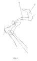
- a motor vehicle pedal in the prior art includes a pedal arm 20' and a fixed bearing 30' used for fixing the pedal arm 20'.
- a position of the pedal arm 20' relative to the fixed bearing 30' is relatively unchanged.
- a height of the motor vehicle pedal is generally designed according to that of 95% of male bodies. For females, due to their smaller soles, when they tread on motor vehicle pedals of the same height, the comfort is poorer.
- the present invention aims to provide a motor vehicle pedal and a motor vehicle having the same, so as to achieve an objective of improving the comfort of the motor vehicle pedal.
- the present invention provides a motor vehicle pedal, including a fixed bearing and a pedal arm disposed on the fixed bearing, where the pedal arm includes a first pedal arm and a second pedal arm, sheathed in the first pedal arm and adjustably disposed along an extending direction of the first pedal arm.
- the motor vehicle pedal further includes a drive assembly, and the drive assembly is in drive connection with the second pedal arm.
- the drive assembly includes a worm assembly and a worm-gear assembly, two ends of the worm assembly are respectively connected to the first pedal arm and the second pedal arm, the worm assembly drives the second pedal arm to move, and the worm-gear assembly is in drive cooperation with the worm assembly.
- first pedal arm is provide with an axial through hole
- second pedal arm includes a connecting end
- the connecting end is disposed inside the axial through hole and is cooperatively connected to the worm assembly.
- the connecting end is provide with an arc transitional portion
- the worm assembly (41) is rotatably disposed in the arc transitional portion, and is capable of driving the second pedal arm to extend outward from the axial through hole or retract into the axial through hole.
- the motor vehicle pedal includes a self-locking state of locking the worm assembly and the worm-gear assembly.
- the drive assembly further includes a drive motor, and a motor shaft of the drive motor is fixedly connected to the worm-gear assembly, so as to drive the worm-gear assembly to rotate.
- an opening portion is disposed on an outer side wall of the first pedal arm, and the worm-gear assembly extends inward from the opening portion and is in drive connection with the worm assembly.
- an accommodating space used for accommodating the drive motor is disposed on an outer side surface of the first pedal arm, and the opening portion and the accommodating space are correspondingly disposed.
- the present invention further provides a motor vehicle, including the foregoing motor vehicle pedal.
- a pedal arm is divided into a first pedal arm and a second pedal arm, and the second pedal arm is adjustably disposed on the first pedal arm, which can change a height of the motor vehicle pedal relative to a chassis surface of a motor vehicle by adjusting a relative position between the first pedal arm and the second pedal arm, so that different consumer groups can perform adjustment according to their own usage habits, thereby achieving an objective of improving the comfort of the motor vehicle pedal.
- first pedal arm 11. axial through hole; 12. accommodating space; 20. second pedal arm; 30. fixed bearing; 40. drive assembly; 41 worm assembly; 42. worm-gear assembly; and 43. drive motor.
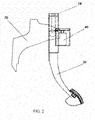
- an embodiment of the present invention provides a motor vehicle pedal, including: a fixed bearing 30 and a pedal arm, where the foregoing pedal arm includes a first pedal arm 10 and a second pedal arm 20.
- the foregoing first pedal arm 10 is detachably disposed on the fixed bearing 30, for pushing the fixed bearing 30 to move.
- the foregoing second pedal arm 20 is sheathed in the first pedal arm 10 and is adjustably disposed along an extending direction of the first pedal arm 10.
- the pedal arm is divided into the first pedal arm 10 and the second pedal arm 20, the second pedal arm 20 is adjustably disposed on the first pedal arm 10, which can change a height of the motor vehicle pedal relative to a chassis surface of a motor vehicle by adjusting a relative position between the first pedal arm 10 and the second pedal arm 20, so that different consumer groups can perform adjustment according to their own usage habits, thereby achieving an objective of improving the comfort of the motor vehicle pedal.
- a first end of the first pedal arm 10 is connected to the foregoing fixed bearing 30, a second end of the first pedal arm 10 extends vertically downward along a direction shown in FIG. 2 and FIG. 3 , and the foregoing first pedal arm 10 is set to a tubular structure and has an axial through hole 11.
- the foregoing second pedal arm 20 includes a connecting end and a pedal end, where the connecting end extends into the interior of the axial through hole 11 from the second end of the first pedal arm 10.
- the foregoing pedal end is located at a side opposite to the connecting end and on the second pedal arm 20, and the foregoing pedal end is disposed outside the axial through hole 11 and bends towards a direction away from the fixed bearing 30, so as to facilitate the treading of a user.
- the axial through hole 11 may further be provided on the second pedal arm 20, and the first pedal arm 10 is disposed inside the axial through hole 11.
- a first limiting portion may be disposed on an inner surface of the second end of the first pedal arm 10, and a second limiting portion cooperating with the first limiting portion may be disposed at the connecting end of the second pedal arm 20.
- a third limiting portion for limiting in cooperation with the second limiting portion may further be disposed at the first end of the first pedal arm 10.
- the motor vehicle pedal further includes a drive assembly 40 that is used for driving the second pedal arm 20 to move along the extending direction of the first pedal arm 10, and the drive assembly 40 is in drive connection with the second pedal arm 20.
- the drive assembly 40 is set, so that the second pedal arm 20 may be driven to move by means of the drive assembly 40, which can make an operation of adjusting the height of the motor vehicle pedal more convenient and quicker, implement an automatic adjustment operation, and save adjustment time.
- the foregoing drive assembly 40 includes a worm assembly 41 and a worm-gear assembly 42.
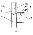
- the worm assembly 41 is disposed on the first pedal arm 10 and extends into the axial through hole 11 from the first end of the first pedal arm 10 to press against the connecting end of the second pedal arm 20, so as to drive the second pedal arm 20 to move.
- the worm-gear assembly 42 extends into the axial through hole 11 from an opening portion disposed on an outer side wall of the first pedal arm 10 and is in drive cooperation with the worm assembly 41.
- an arc transitional portion is disposed at the connecting end of the second pedal arm 20, and an end of the worm assembly 41 is rotatably disposed in the arc transitional portion, and drives the foregoing second pedal arm 20 to make vertically reciprocating movement. That is, driven by the worm-gear assembly 42, the foregoing worm assembly 41 itself rotates and moves upward or downward.
- the second pedal arm 20 is provided with the arc transitional portion, the second pedal arm 20 does not rotate along with the worm assembly 41, and only makes the vertically reciprocating movement along with the worm assembly 41.
- a buckling table is disposed at the end, of the foregoing worm assembly 41, connected to the arc transitional portion, and the buckling table is located above a tip of the worm assembly 41, that is, there is a certain distance between the end of the worm assembly 41 and the buckling table.
- a buckling and cooperating portion cooperating with the buckling table is disposed on the foregoing arc transitional portion.
- the tip of the worm assembly 41 is relied on to push the second pedal arm 20 out of the axial through hole 11; and if the second pedal arm 20 needs to retract, the worm assembly 41 moves upward and pulls up the second pedal arm 20 by connecting the buckling table and the buckling and cooperating portion.
- the drive assembly 40 has a self-locking state of locking the worm-gear assembly 42 and the worm assembly 41, so that the worm assembly 41 is capable of driving the worm-gear assembly 42 to move forward or backward around an axial direction thereof. Otherwise, the worm assembly 41 is incapable of driving the worm-gear assembly 42 to move towards any direction, thereby playing a role of positioning and locking the second pedal arm 20.
- the drive assembly 40 further includes a drive motor 43, and a motor shaft of the drive motor 43 is fixedly connected to the worm-gear assembly 42, so as to drive the worm-gear assembly 42 to rotate.
- the drive motor 43 in this embodiment of the present invention is capable of rotating forward or backward, so as to drive the worm-gear assembly 42 to make forward or backward movement.
- an accommodating space 12 used for accommodating the drive motor 43 is disposed on an outer side surface of the first pedal arm 10.
- the drive motor 43 is placed inside the accommodating space 12
- the worm-gear assembly 42 is installed on the motor shaft of the drive motor 43
- the worm-gear assembly 42 penetrates, from the accommodating space 12, the opening portion formed at a set position on an outer surface of the first pedal arm 10, and is in drive connection with the worm assembly 41 disposed in the axial through hole 11.
- the foregoing opening portion and the foregoing accommodating space 12 are correspondingly disposed.
- a first buckling and positioning portion is disposed on the foregoing first pedal arm 10
- a second buckling and positioning portion is disposed on the second pedal arm 20
- the first buckling and positioning portion is cooperatively buckled with the second buckling and positioning portion, so as to fix the second pedal arm 20 onto the first pedal arm 10.
- the first buckling and positioning portion may be multiple spaced buckling slots disposed on the outer surface of the first pedal arm 10, and the second buckling and positioning portion may be buckling bulges disposed on the second pedal arm 20 and cooperatively buckled with the buckling slots. During adjustment, it only needs to move the second pedal arm 20 to a suitable position and then tightly buckle the buckling bulges with the corresponding buckling slots.
- other features are the same as those in the foregoing embodiment.
- the foregoing drive motor may further be connected to a leading screw for driving the leading screw to rotate, so as to drive the second pedal arm 20 to make reciprocating movement along the extending direction of the first pedal arm 10, thereby achieving an objective of changing the height between the pedal arm and the chassis surface. Except the foregoing features, other features are the same as those in the first embodiment.
- the present invention further provides a motor vehicle, including the foregoing motor vehicle pedal.
- the motor vehicle pedal of the present invention is adjustable in height, so that the pedal is applicable to different vehicle models, which enhances the applicability of the motor vehicle pedal.
Landscapes
- Engineering & Computer Science (AREA)
- Physics & Mathematics (AREA)
- General Physics & Mathematics (AREA)
- Automation & Control Theory (AREA)
- Transportation (AREA)
- Mechanical Engineering (AREA)
- Mechanical Control Devices (AREA)
- Arrangement And Mounting Of Devices That Control Transmission Of Motive Force (AREA)
- Auxiliary Drives, Propulsion Controls, And Safety Devices (AREA)
Abstract
Description
- The present invention relates to the field of motor vehicles, and in particular, to a motor vehicle pedal and a motor vehicle having the same.
- As shown in
FIG.1 , a motor vehicle pedal in the prior art includes a pedal arm 20' and a fixed bearing 30' used for fixing the pedal arm 20'. In the prior art, a position of the pedal arm 20' relative to the fixed bearing 30' is relatively unchanged. In addition, during design, a height of the motor vehicle pedal is generally designed according to that of 95% of male bodies. For females, due to their smaller soles, when they tread on motor vehicle pedals of the same height, the comfort is poorer. - The present invention aims to provide a motor vehicle pedal and a motor vehicle having the same, so as to achieve an objective of improving the comfort of the motor vehicle pedal.
- In order to achieve the foregoing objective, the present invention provides a motor vehicle pedal, including a fixed bearing and a pedal arm disposed on the fixed bearing, where the pedal arm includes a first pedal arm and a second pedal arm, sheathed in the first pedal arm and adjustably disposed along an extending direction of the first pedal arm.
- Further, the motor vehicle pedal further includes a drive assembly, and the drive assembly is in drive connection with the second pedal arm.
- Further, the drive assembly includes a worm assembly and a worm-gear assembly, two ends of the worm assembly are respectively connected to the first pedal arm and the second pedal arm, the worm assembly drives the second pedal arm to move, and the worm-gear assembly is in drive cooperation with the worm assembly.
- Further, the first pedal arm is provide with an axial through hole, the second pedal arm includes a connecting end, and the connecting end is disposed inside the axial through hole and is cooperatively connected to the worm assembly.
- Further, the connecting end is provide with an arc transitional portion, and the worm assembly (41) is rotatably disposed in the arc transitional portion, and is capable of driving the second pedal arm to extend outward from the axial through hole or retract into the axial through hole.
- Further, the motor vehicle pedal includes a self-locking state of locking the worm assembly and the worm-gear assembly.
- Further, the drive assembly further includes a drive motor, and a motor shaft of the drive motor is fixedly connected to the worm-gear assembly, so as to drive the worm-gear assembly to rotate.
- Further, an opening portion is disposed on an outer side wall of the first pedal arm, and the worm-gear assembly extends inward from the opening portion and is in drive connection with the worm assembly.
- Further, an accommodating space used for accommodating the drive motor is disposed on an outer side surface of the first pedal arm, and the opening portion and the accommodating space are correspondingly disposed.
- The present invention further provides a motor vehicle, including the foregoing motor vehicle pedal.
- By using the motor vehicle pedal of the present invention, a pedal arm is divided into a first pedal arm and a second pedal arm, and the second pedal arm is adjustably disposed on the first pedal arm, which can change a height of the motor vehicle pedal relative to a chassis surface of a motor vehicle by adjusting a relative position between the first pedal arm and the second pedal arm, so that different consumer groups can perform adjustment according to their own usage habits, thereby achieving an objective of improving the comfort of the motor vehicle pedal.
- The accompanying drawings in this specification which constitute a part of this application are intended to provide further understanding of the present invention. Exemplary embodiments of the present invention and description thereof are intended to explain the present invention, without constituting an improper limit to the present invention. In the accompanying drawings:
-
FIG. 1 is a schematic structural diagram of a motor vehicle pedal in the prior art; -
FIG. 2 is a schematic structural diagram of a motor vehicle pedal according to an embodiment of the present invention; and -
FIG. 3 is a partially enlarged schematic structural diagram of a motor vehicle pedal according to an embodiment of the present invention. - Reference numerals in the drawings: 10. first pedal arm; 11. axial through hole; 12. accommodating space; 20. second pedal arm; 30. fixed bearing; 40. drive assembly; 41 worm assembly; 42. worm-gear assembly; and 43. drive motor.
- It should be noted that embodiments in this application and features in the embodiments can be combined without any conflict. The present invention is described in detail with reference to accompanying drawings and in combination with the embodiments in the following.
- As shown in
FIG. 2 andFIG. 3 , an embodiment of the present invention provides a motor vehicle pedal, including: a fixed bearing 30 and a pedal arm, where the foregoing pedal arm includes afirst pedal arm 10 and asecond pedal arm 20. The foregoingfirst pedal arm 10 is detachably disposed on the fixed bearing 30, for pushing the fixed bearing 30 to move. The foregoingsecond pedal arm 20 is sheathed in thefirst pedal arm 10 and is adjustably disposed along an extending direction of thefirst pedal arm 10. - The pedal arm is divided into the
first pedal arm 10 and thesecond pedal arm 20, thesecond pedal arm 20 is adjustably disposed on thefirst pedal arm 10, which can change a height of the motor vehicle pedal relative to a chassis surface of a motor vehicle by adjusting a relative position between thefirst pedal arm 10 and thesecond pedal arm 20, so that different consumer groups can perform adjustment according to their own usage habits, thereby achieving an objective of improving the comfort of the motor vehicle pedal. - Specifically, a first end of the
first pedal arm 10 is connected to the foregoing fixed bearing 30, a second end of thefirst pedal arm 10 extends vertically downward along a direction shown inFIG. 2 andFIG. 3 , and the foregoingfirst pedal arm 10 is set to a tubular structure and has an axial throughhole 11. The foregoingsecond pedal arm 20 includes a connecting end and a pedal end, where the connecting end extends into the interior of the axial throughhole 11 from the second end of thefirst pedal arm 10. The foregoing pedal end is located at a side opposite to the connecting end and on thesecond pedal arm 20, and the foregoing pedal end is disposed outside the axial throughhole 11 and bends towards a direction away from the fixed bearing 30, so as to facilitate the treading of a user. Certainly, during, the present invention is not limited to the foregoing single installation manner. For example, the axial throughhole 11 may further be provided on thesecond pedal arm 20, and thefirst pedal arm 10 is disposed inside the axial throughhole 11. - It should be noted that in order that the
first pedal arm 10 and thesecond pedal arm 20 will not separate during use, in this embodiment, a first limiting portion may be disposed on an inner surface of the second end of thefirst pedal arm 10, and a second limiting portion cooperating with the first limiting portion may be disposed at the connecting end of thesecond pedal arm 20. When thesecond pedal arm 20 moves to the foregoing limiting portion, thesecond pedal arm 20 cannot keep moving. Likewise, in order to prevent thesecond pedal arm 20 from penetrating outward from the first end of thefirst pedal arm 10, in this embodiment of the present invention, a third limiting portion for limiting in cooperation with the second limiting portion may further be disposed at the first end of thefirst pedal arm 10. - Preferably, the motor vehicle pedal further includes a
drive assembly 40 that is used for driving thesecond pedal arm 20 to move along the extending direction of thefirst pedal arm 10, and thedrive assembly 40 is in drive connection with thesecond pedal arm 20. Thedrive assembly 40 is set, so that thesecond pedal arm 20 may be driven to move by means of thedrive assembly 40, which can make an operation of adjusting the height of the motor vehicle pedal more convenient and quicker, implement an automatic adjustment operation, and save adjustment time. - The
foregoing drive assembly 40 includes aworm assembly 41 and a worm-gear assembly 42. Theworm assembly 41 is disposed on thefirst pedal arm 10 and extends into the axial throughhole 11 from the first end of thefirst pedal arm 10 to press against the connecting end of thesecond pedal arm 20, so as to drive thesecond pedal arm 20 to move. The worm-gear assembly 42 extends into the axial throughhole 11 from an opening portion disposed on an outer side wall of thefirst pedal arm 10 and is in drive cooperation with theworm assembly 41. - It should be noted that in this embodiment of the present invention, an arc transitional portion is disposed at the connecting end of the
second pedal arm 20, and an end of theworm assembly 41 is rotatably disposed in the arc transitional portion, and drives the foregoingsecond pedal arm 20 to make vertically reciprocating movement. That is, driven by the worm-gear assembly 42, theforegoing worm assembly 41 itself rotates and moves upward or downward. However, because thesecond pedal arm 20 is provided with the arc transitional portion, thesecond pedal arm 20 does not rotate along with theworm assembly 41, and only makes the vertically reciprocating movement along with theworm assembly 41. - Specifically, a buckling table is disposed at the end, of the
foregoing worm assembly 41, connected to the arc transitional portion, and the buckling table is located above a tip of theworm assembly 41, that is, there is a certain distance between the end of theworm assembly 41 and the buckling table. A buckling and cooperating portion cooperating with the buckling table is disposed on the foregoing arc transitional portion. During work, if thesecond pedal arm 20 needs to move downward, the tip of theworm assembly 41 is relied on to push thesecond pedal arm 20 out of the axial throughhole 11; and if thesecond pedal arm 20 needs to retract, theworm assembly 41 moves upward and pulls up thesecond pedal arm 20 by connecting the buckling table and the buckling and cooperating portion. - Preferably, in order that the position of the
second pedal arm 20 can be kept unchanged after thesecond pedal arm 20 is adjusted to an ideal position, in this embodiment of the present invention, thedrive assembly 40 has a self-locking state of locking the worm-gear assembly 42 and theworm assembly 41, so that theworm assembly 41 is capable of driving the worm-gear assembly 42 to move forward or backward around an axial direction thereof. Otherwise, theworm assembly 41 is incapable of driving the worm-gear assembly 42 to move towards any direction, thereby playing a role of positioning and locking thesecond pedal arm 20. - Further, the
drive assembly 40 further includes adrive motor 43, and a motor shaft of thedrive motor 43 is fixedly connected to the worm-gear assembly 42, so as to drive the worm-gear assembly 42 to rotate. Thedrive motor 43 in this embodiment of the present invention is capable of rotating forward or backward, so as to drive the worm-gear assembly 42 to make forward or backward movement. - In order to save space, in this embodiment of the present invention, an
accommodating space 12 used for accommodating thedrive motor 43 is disposed on an outer side surface of the firstpedal arm 10. During installation, thedrive motor 43 is placed inside theaccommodating space 12, the worm-gear assembly 42 is installed on the motor shaft of thedrive motor 43, and the worm-gear assembly 42 penetrates, from theaccommodating space 12, the opening portion formed at a set position on an outer surface of the firstpedal arm 10, and is in drive connection with theworm assembly 41 disposed in the axial throughhole 11. It should be noted that the foregoing opening portion and the foregoingaccommodating space 12 are correspondingly disposed. - Certainly, the present invention is not limited to the foregoing embodiment. In another embodiment, a first buckling and positioning portion is disposed on the foregoing first
pedal arm 10, a second buckling and positioning portion is disposed on the secondpedal arm 20, the first buckling and positioning portion is cooperatively buckled with the second buckling and positioning portion, so as to fix the secondpedal arm 20 onto the firstpedal arm 10. - Specifically, the first buckling and positioning portion may be multiple spaced buckling slots disposed on the outer surface of the first
pedal arm 10, and the second buckling and positioning portion may be buckling bulges disposed on the secondpedal arm 20 and cooperatively buckled with the buckling slots. During adjustment, it only needs to move the secondpedal arm 20 to a suitable position and then tightly buckle the buckling bulges with the corresponding buckling slots. In this embodiment, except the foregoing features, other features are the same as those in the foregoing embodiment. - In a third embodiment, the foregoing drive motor may further be connected to a leading screw for driving the leading screw to rotate, so as to drive the second
pedal arm 20 to make reciprocating movement along the extending direction of the firstpedal arm 10, thereby achieving an objective of changing the height between the pedal arm and the chassis surface. Except the foregoing features, other features are the same as those in the first embodiment. - The present invention further provides a motor vehicle, including the foregoing motor vehicle pedal.
- As can be seen from the foregoing description, the foregoing embodiments of the present invention achieve the following technical effects:
- A pedal arm is divided into a first pedal arm and a second pedal arm, and the second pedal arm is adjustably disposed on the first pedal arm, which can change a height of the motor vehicle pedal relative to a chassis surface of a motor vehicle by adjusting a relative position between the first pedal arm and the second pedal arm, so that different consumer groups can perform adjustment according to their own usage habits, thereby achieving an objective of improving the comfort of the motor vehicle pedal.
- Further, the motor vehicle pedal of the present invention is adjustable in height, so that the pedal is applicable to different vehicle models, which enhances the applicability of the motor vehicle pedal.
- The foregoing descriptions are merely preferable embodiments of the present invention, but are not intended to limit the present invention. A person skilled in the art may make various modifications and changes to the present invention. Any modification, equivalent replacement, and improvement made without departing from the spirit and principle of the present invention shall fall within the protection scope of the present invention.
Claims (10)
- A motor vehicle pedal, comprising a fixed bearing (30) and a pedal arm disposed on the fixed bearing (30), wherein the pedal arm comprises:a first pedal arm (10); anda second pedal arm (20), sheathed in the first pedal arm (10) and adjustably disposed along an extending direction of the first pedal arm (10).
- The motor vehicle pedal according to claim 1, wherein the motor vehicle pedal further comprises a drive assembly (40), and the drive assembly (40) is in drive connection with the second pedal arm (20).
- The motor vehicle pedal according to claim 2, wherein the drive assembly (40) comprises a worm assembly (41) and a worm-gear assembly (42), two ends of the worm assembly (41) are respectively connected to the first pedal arm (10) and the second pedal arm (20), the worm assembly (41) drives the second pedal arm (20) to move, and the worm-gear assembly (42) is in drive cooperation with the worm assembly (41).
- The motor vehicle pedal according to claim 3, wherein the first pedal arm (10) is provide with an axial through hole (11), the second pedal arm (20) comprises a connecting end, and the connecting end is disposed inside the axial through hole (11) and is cooperatively connected to the worm assembly (41).
- The motor vehicle pedal according to claim 4, wherein the connecting end is provide with an arc transitional portion, and the worm assembly (41) is rotatably disposed in the arc transitional portion, and is capable of driving the second pedal arm (20) to extend outward from the axial through hole (11) or retract into the axial through hole (11).
- The motor vehicle pedal according to claim 3, wherein the motor vehicle pedal comprises a self-locking state of locking the worm assembly (41) and the worm-gear assembly (42).
- The motor vehicle pedal according to claim 3, wherein the drive assembly (40) further comprises a drive motor (43), and a motor shaft of the drive motor (43) is fixedly connected to the worm-gear assembly (42), so as to drive the worm-gear assembly (42) to rotate.
- The motor vehicle pedal according to claim 7, wherein an opening portion is disposed on an outer side wall of the first pedal arm (10), and the worm-gear assembly (42) extends inward from the opening portion and is in drive connection with the worm assembly (41).
- The motor vehicle pedal according to claim 8, wherein an accommodating space (12) used for accommodating the drive motor (43) is disposed on an outer side surface of the first pedal arm (10), and the opening portion and the accommodating space (12) are correspondingly disposed.
- A motor vehicle, comprising a motor vehicle pedal, wherein the motor vehicle pedal is the motor vehicle pedal according to any one of claims 1 to 9.
Applications Claiming Priority (1)
| Application Number | Priority Date | Filing Date | Title |
|---|---|---|---|
| CN201410409481.1A CN104827905A (en) | 2014-08-19 | 2014-08-19 | Motor vehicle pedal and motor vehicle with same |
Publications (3)
| Publication Number | Publication Date |
|---|---|
| EP3000668A2 true EP3000668A2 (en) | 2016-03-30 |
| EP3000668A3 EP3000668A3 (en) | 2016-05-25 |
| EP3000668B1 EP3000668B1 (en) | 2019-04-03 |
Family
ID=52446271
Family Applications (1)
| Application Number | Title | Priority Date | Filing Date |
|---|---|---|---|
| EP15153803.0A Active EP3000668B1 (en) | 2014-08-19 | 2015-02-04 | Motor vehicle pedal and motor vehicle having the same |
Country Status (2)
| Country | Link |
|---|---|
| EP (1) | EP3000668B1 (en) |
| CN (1) | CN104827905A (en) |
Families Citing this family (3)
| Publication number | Priority date | Publication date | Assignee | Title |
|---|---|---|---|---|
| CN110182189A (en) * | 2019-05-29 | 2019-08-30 | 北京汽车股份有限公司 | For the brake pedal component of vehicle and with its vehicle |
| CN113183932B (en) * | 2021-06-16 | 2025-07-22 | 杭叉集团股份有限公司 | Adjustable operation pedal mechanism of industrial vehicle |
| CN115071646A (en) * | 2022-07-04 | 2022-09-20 | 浙江泰鸿万立科技股份有限公司 | Telescopic braking of intelligence driving and accelerator pedal subassembly |
Family Cites Families (7)
| Publication number | Priority date | Publication date | Assignee | Title |
|---|---|---|---|---|
| US3301088A (en) * | 1964-03-02 | 1967-01-31 | Gen Motors Corp | Vehicle adjustable control pedal assemblies |
| DE20022852U1 (en) * | 2000-01-27 | 2002-05-23 | Teleflex Automotive Germany GmbH, 37586 Dassel | Adjustable pedal |
| US6367348B1 (en) * | 2000-05-01 | 2002-04-09 | Dura Global Technologies, Inc. | Adjustable brake, clutch and accelerator pedals |
| US6367349B1 (en) * | 2000-05-01 | 2002-04-09 | Dura Global Technologies, Inc. | Adjustable brake, clutch and accelerator pedals |
| US20030084749A1 (en) * | 2001-11-05 | 2003-05-08 | Orr Brian Norman | Adjustable pedal assembly with pedal ratio compensation |
| FR2844226A1 (en) * | 2002-09-09 | 2004-03-12 | Robert Mazenq | Second accelerator pedal for resting one foot/leg during long vehicle journeys, comprises pedal which is separately attached to engine, parked on magnet when not used and located opposite normally unused leg |
| KR20040028194A (en) * | 2002-09-30 | 2004-04-03 | 현대모비스 주식회사 | length variable car pedal |
-
2014
- 2014-08-19 CN CN201410409481.1A patent/CN104827905A/en active Pending
-
2015
- 2015-02-04 EP EP15153803.0A patent/EP3000668B1/en active Active
Non-Patent Citations (1)
| Title |
|---|
| None |
Also Published As
| Publication number | Publication date |
|---|---|
| EP3000668A3 (en) | 2016-05-25 |
| EP3000668B1 (en) | 2019-04-03 |
| CN104827905A (en) | 2015-08-12 |
Similar Documents
| Publication | Publication Date | Title |
|---|---|---|
| JP6364915B2 (en) | Vehicle seat slide device | |
| US20210309277A1 (en) | Adjusting drive for a steering column and steering column for a motor vehicle | |
| CN205033973U (en) | Car seat's adjustable mechanism | |
| MX2011006548A (en) | Adjusting device having a spindle drive. | |
| US20150090856A1 (en) | Conveyance seat | |
| CN108602523A (en) | The steering column for being electrically adjusted length for motor vehicles | |
| EP3000668B1 (en) | Motor vehicle pedal and motor vehicle having the same | |
| WO2013009060A3 (en) | Wheel assembly of mobile robot | |
| US10160474B2 (en) | Telescopic latch apparatus of steering column for vehicle | |
| JP2016049804A (en) | Slide rail of vehicle seat | |
| EP1925510A3 (en) | Interior structure of vehicle equipped with curtain airbag device | |
| EP1834839A3 (en) | In-vehicle apparatus | |
| EP2366601A3 (en) | Steering device | |
| CN106536984A (en) | Linear actuator | |
| JP6211647B2 (en) | Complete walk-in device | |
| CN107000675A (en) | Safety belt lock presenter | |
| US20180244300A1 (en) | Adjustable steering column for motor vehicles with energy absorber for vehicle crashes | |
| WO2009034814A1 (en) | Aerodynamic structure for vehicle | |
| US20170219125A1 (en) | Clip and Clip Arrangement | |
| US9771027B2 (en) | Console support panel and console assembly employing the same | |
| KR101558102B1 (en) | Mandrel for square pipe bendings that have flap and slide plate | |
| JP5602699B2 (en) | Mirror device for vehicle | |
| EP2151338A3 (en) | Rear garnish clip | |
| WO2015110283A3 (en) | Kick-down element for a motor vehicle | |
| JP6785607B2 (en) | Drive device |
Legal Events
| Date | Code | Title | Description |
|---|---|---|---|
| PUAI | Public reference made under article 153(3) epc to a published international application that has entered the european phase |
Free format text: ORIGINAL CODE: 0009012 |
|
| AK | Designated contracting states |
Kind code of ref document: A2 Designated state(s): AL AT BE BG CH CY CZ DE DK EE ES FI FR GB GR HR HU IE IS IT LI LT LU LV MC MK MT NL NO PL PT RO RS SE SI SK SM TR |
|
| AX | Request for extension of the european patent |
Extension state: BA ME |
|
| PUAL | Search report despatched |
Free format text: ORIGINAL CODE: 0009013 |
|
| AK | Designated contracting states |
Kind code of ref document: A3 Designated state(s): AL AT BE BG CH CY CZ DE DK EE ES FI FR GB GR HR HU IE IS IT LI LT LU LV MC MK MT NL NO PL PT RO RS SE SI SK SM TR |
|
| AX | Request for extension of the european patent |
Extension state: BA ME |
|
| RIC1 | Information provided on ipc code assigned before grant |
Ipc: G05G 1/42 20080401ALI20160418BHEP Ipc: B60T 7/06 20060101AFI20160418BHEP |
|
| 17P | Request for examination filed |
Effective date: 20160713 |
|
| RBV | Designated contracting states (corrected) |
Designated state(s): AL AT BE BG CH CY CZ DE DK EE ES FI FR GB GR HR HU IE IS IT LI LT LU LV MC MK MT NL NO PL PT RO RS SE SI SK SM TR |
|
| STAA | Information on the status of an ep patent application or granted ep patent |
Free format text: STATUS: EXAMINATION IS IN PROGRESS |
|
| 17Q | First examination report despatched |
Effective date: 20180326 |
|
| GRAP | Despatch of communication of intention to grant a patent |
Free format text: ORIGINAL CODE: EPIDOSNIGR1 |
|
| STAA | Information on the status of an ep patent application or granted ep patent |
Free format text: STATUS: GRANT OF PATENT IS INTENDED |
|
| INTG | Intention to grant announced |
Effective date: 20181121 |
|
| RIN1 | Information on inventor provided before grant (corrected) |
Inventor name: JIN, DAWEI Inventor name: YANG, YANING |
|
| RIC1 | Information provided on ipc code assigned before grant |
Ipc: G05G 1/42 20080401ALI20160418BHEP Ipc: B60T 7/06 20060101AFI20160418BHEP |
|
| GRAS | Grant fee paid |
Free format text: ORIGINAL CODE: EPIDOSNIGR3 |
|
| GRAA | (expected) grant |
Free format text: ORIGINAL CODE: 0009210 |
|
| STAA | Information on the status of an ep patent application or granted ep patent |
Free format text: STATUS: THE PATENT HAS BEEN GRANTED |
|
| AK | Designated contracting states |
Kind code of ref document: B1 Designated state(s): AL AT BE BG CH CY CZ DE DK EE ES FI FR GB GR HR HU IE IS IT LI LT LU LV MC MK MT NL NO PL PT RO RS SE SI SK SM TR |
|
| REG | Reference to a national code |
Ref country code: GB Ref legal event code: FG4D |
|
| REG | Reference to a national code |
Ref country code: CH Ref legal event code: EP Ref country code: AT Ref legal event code: REF Ref document number: 1115352 Country of ref document: AT Kind code of ref document: T Effective date: 20190415 |
|
| REG | Reference to a national code |
Ref country code: DE Ref legal event code: R096 Ref document number: 602015027410 Country of ref document: DE |
|
| REG | Reference to a national code |
Ref country code: IE Ref legal event code: FG4D |
|
| REG | Reference to a national code |
Ref country code: NL Ref legal event code: MP Effective date: 20190403 |
|
| REG | Reference to a national code |
Ref country code: LT Ref legal event code: MG4D |
|
| REG | Reference to a national code |
Ref country code: AT Ref legal event code: MK05 Ref document number: 1115352 Country of ref document: AT Kind code of ref document: T Effective date: 20190403 |
|
| PG25 | Lapsed in a contracting state [announced via postgrant information from national office to epo] |
Ref country code: NL Free format text: LAPSE BECAUSE OF FAILURE TO SUBMIT A TRANSLATION OF THE DESCRIPTION OR TO PAY THE FEE WITHIN THE PRESCRIBED TIME-LIMIT Effective date: 20190403 |
|
| PG25 | Lapsed in a contracting state [announced via postgrant information from national office to epo] |
Ref country code: NO Free format text: LAPSE BECAUSE OF FAILURE TO SUBMIT A TRANSLATION OF THE DESCRIPTION OR TO PAY THE FEE WITHIN THE PRESCRIBED TIME-LIMIT Effective date: 20190703 Ref country code: HR Free format text: LAPSE BECAUSE OF FAILURE TO SUBMIT A TRANSLATION OF THE DESCRIPTION OR TO PAY THE FEE WITHIN THE PRESCRIBED TIME-LIMIT Effective date: 20190403 Ref country code: SE Free format text: LAPSE BECAUSE OF FAILURE TO SUBMIT A TRANSLATION OF THE DESCRIPTION OR TO PAY THE FEE WITHIN THE PRESCRIBED TIME-LIMIT Effective date: 20190403 Ref country code: FI Free format text: LAPSE BECAUSE OF FAILURE TO SUBMIT A TRANSLATION OF THE DESCRIPTION OR TO PAY THE FEE WITHIN THE PRESCRIBED TIME-LIMIT Effective date: 20190403 Ref country code: AL Free format text: LAPSE BECAUSE OF FAILURE TO SUBMIT A TRANSLATION OF THE DESCRIPTION OR TO PAY THE FEE WITHIN THE PRESCRIBED TIME-LIMIT Effective date: 20190403 Ref country code: PT Free format text: LAPSE BECAUSE OF FAILURE TO SUBMIT A TRANSLATION OF THE DESCRIPTION OR TO PAY THE FEE WITHIN THE PRESCRIBED TIME-LIMIT Effective date: 20190803 Ref country code: CZ Free format text: LAPSE BECAUSE OF FAILURE TO SUBMIT A TRANSLATION OF THE DESCRIPTION OR TO PAY THE FEE WITHIN THE PRESCRIBED TIME-LIMIT Effective date: 20190403 Ref country code: LT Free format text: LAPSE BECAUSE OF FAILURE TO SUBMIT A TRANSLATION OF THE DESCRIPTION OR TO PAY THE FEE WITHIN THE PRESCRIBED TIME-LIMIT Effective date: 20190403 Ref country code: ES Free format text: LAPSE BECAUSE OF FAILURE TO SUBMIT A TRANSLATION OF THE DESCRIPTION OR TO PAY THE FEE WITHIN THE PRESCRIBED TIME-LIMIT Effective date: 20190403 |
|
| PG25 | Lapsed in a contracting state [announced via postgrant information from national office to epo] |
Ref country code: BG Free format text: LAPSE BECAUSE OF FAILURE TO SUBMIT A TRANSLATION OF THE DESCRIPTION OR TO PAY THE FEE WITHIN THE PRESCRIBED TIME-LIMIT Effective date: 20190703 Ref country code: LV Free format text: LAPSE BECAUSE OF FAILURE TO SUBMIT A TRANSLATION OF THE DESCRIPTION OR TO PAY THE FEE WITHIN THE PRESCRIBED TIME-LIMIT Effective date: 20190403 Ref country code: RS Free format text: LAPSE BECAUSE OF FAILURE TO SUBMIT A TRANSLATION OF THE DESCRIPTION OR TO PAY THE FEE WITHIN THE PRESCRIBED TIME-LIMIT Effective date: 20190403 Ref country code: PL Free format text: LAPSE BECAUSE OF FAILURE TO SUBMIT A TRANSLATION OF THE DESCRIPTION OR TO PAY THE FEE WITHIN THE PRESCRIBED TIME-LIMIT Effective date: 20190403 Ref country code: GR Free format text: LAPSE BECAUSE OF FAILURE TO SUBMIT A TRANSLATION OF THE DESCRIPTION OR TO PAY THE FEE WITHIN THE PRESCRIBED TIME-LIMIT Effective date: 20190704 |
|
| PG25 | Lapsed in a contracting state [announced via postgrant information from national office to epo] |
Ref country code: AT Free format text: LAPSE BECAUSE OF FAILURE TO SUBMIT A TRANSLATION OF THE DESCRIPTION OR TO PAY THE FEE WITHIN THE PRESCRIBED TIME-LIMIT Effective date: 20190403 Ref country code: IS Free format text: LAPSE BECAUSE OF FAILURE TO SUBMIT A TRANSLATION OF THE DESCRIPTION OR TO PAY THE FEE WITHIN THE PRESCRIBED TIME-LIMIT Effective date: 20190803 |
|
| REG | Reference to a national code |
Ref country code: DE Ref legal event code: R097 Ref document number: 602015027410 Country of ref document: DE |
|
| PG25 | Lapsed in a contracting state [announced via postgrant information from national office to epo] |
Ref country code: RO Free format text: LAPSE BECAUSE OF FAILURE TO SUBMIT A TRANSLATION OF THE DESCRIPTION OR TO PAY THE FEE WITHIN THE PRESCRIBED TIME-LIMIT Effective date: 20190403 Ref country code: DK Free format text: LAPSE BECAUSE OF FAILURE TO SUBMIT A TRANSLATION OF THE DESCRIPTION OR TO PAY THE FEE WITHIN THE PRESCRIBED TIME-LIMIT Effective date: 20190403 Ref country code: EE Free format text: LAPSE BECAUSE OF FAILURE TO SUBMIT A TRANSLATION OF THE DESCRIPTION OR TO PAY THE FEE WITHIN THE PRESCRIBED TIME-LIMIT Effective date: 20190403 Ref country code: SK Free format text: LAPSE BECAUSE OF FAILURE TO SUBMIT A TRANSLATION OF THE DESCRIPTION OR TO PAY THE FEE WITHIN THE PRESCRIBED TIME-LIMIT Effective date: 20190403 |
|
| PLBE | No opposition filed within time limit |
Free format text: ORIGINAL CODE: 0009261 |
|
| STAA | Information on the status of an ep patent application or granted ep patent |
Free format text: STATUS: NO OPPOSITION FILED WITHIN TIME LIMIT |
|
| PG25 | Lapsed in a contracting state [announced via postgrant information from national office to epo] |
Ref country code: SM Free format text: LAPSE BECAUSE OF FAILURE TO SUBMIT A TRANSLATION OF THE DESCRIPTION OR TO PAY THE FEE WITHIN THE PRESCRIBED TIME-LIMIT Effective date: 20190403 Ref country code: IT Free format text: LAPSE BECAUSE OF FAILURE TO SUBMIT A TRANSLATION OF THE DESCRIPTION OR TO PAY THE FEE WITHIN THE PRESCRIBED TIME-LIMIT Effective date: 20190403 |
|
| 26N | No opposition filed |
Effective date: 20200106 |
|
| PG25 | Lapsed in a contracting state [announced via postgrant information from national office to epo] |
Ref country code: TR Free format text: LAPSE BECAUSE OF FAILURE TO SUBMIT A TRANSLATION OF THE DESCRIPTION OR TO PAY THE FEE WITHIN THE PRESCRIBED TIME-LIMIT Effective date: 20190403 |
|
| PG25 | Lapsed in a contracting state [announced via postgrant information from national office to epo] |
Ref country code: SI Free format text: LAPSE BECAUSE OF FAILURE TO SUBMIT A TRANSLATION OF THE DESCRIPTION OR TO PAY THE FEE WITHIN THE PRESCRIBED TIME-LIMIT Effective date: 20190403 |
|
| REG | Reference to a national code |
Ref country code: DE Ref legal event code: R119 Ref document number: 602015027410 Country of ref document: DE |
|
| REG | Reference to a national code |
Ref country code: CH Ref legal event code: PL |
|
| GBPC | Gb: european patent ceased through non-payment of renewal fee |
Effective date: 20200204 |
|
| REG | Reference to a national code |
Ref country code: BE Ref legal event code: MM Effective date: 20200229 |
|
| PG25 | Lapsed in a contracting state [announced via postgrant information from national office to epo] |
Ref country code: LU Free format text: LAPSE BECAUSE OF NON-PAYMENT OF DUE FEES Effective date: 20200204 Ref country code: MC Free format text: LAPSE BECAUSE OF FAILURE TO SUBMIT A TRANSLATION OF THE DESCRIPTION OR TO PAY THE FEE WITHIN THE PRESCRIBED TIME-LIMIT Effective date: 20190403 |
|
| PG25 | Lapsed in a contracting state [announced via postgrant information from national office to epo] |
Ref country code: CH Free format text: LAPSE BECAUSE OF NON-PAYMENT OF DUE FEES Effective date: 20200229 Ref country code: LI Free format text: LAPSE BECAUSE OF NON-PAYMENT OF DUE FEES Effective date: 20200229 |
|
| PG25 | Lapsed in a contracting state [announced via postgrant information from national office to epo] |
Ref country code: DE Free format text: LAPSE BECAUSE OF NON-PAYMENT OF DUE FEES Effective date: 20200901 Ref country code: GB Free format text: LAPSE BECAUSE OF NON-PAYMENT OF DUE FEES Effective date: 20200204 Ref country code: FR Free format text: LAPSE BECAUSE OF NON-PAYMENT OF DUE FEES Effective date: 20200229 Ref country code: IE Free format text: LAPSE BECAUSE OF NON-PAYMENT OF DUE FEES Effective date: 20200204 |
|
| PG25 | Lapsed in a contracting state [announced via postgrant information from national office to epo] |
Ref country code: BE Free format text: LAPSE BECAUSE OF NON-PAYMENT OF DUE FEES Effective date: 20200229 |
|
| PG25 | Lapsed in a contracting state [announced via postgrant information from national office to epo] |
Ref country code: MT Free format text: LAPSE BECAUSE OF FAILURE TO SUBMIT A TRANSLATION OF THE DESCRIPTION OR TO PAY THE FEE WITHIN THE PRESCRIBED TIME-LIMIT Effective date: 20190403 Ref country code: CY Free format text: LAPSE BECAUSE OF FAILURE TO SUBMIT A TRANSLATION OF THE DESCRIPTION OR TO PAY THE FEE WITHIN THE PRESCRIBED TIME-LIMIT Effective date: 20190403 |
|
| PG25 | Lapsed in a contracting state [announced via postgrant information from national office to epo] |
Ref country code: MK Free format text: LAPSE BECAUSE OF FAILURE TO SUBMIT A TRANSLATION OF THE DESCRIPTION OR TO PAY THE FEE WITHIN THE PRESCRIBED TIME-LIMIT Effective date: 20190403 |