EP3000604A2 - Print device - Google Patents
Print device Download PDFInfo
- Publication number
- EP3000604A2 EP3000604A2 EP15185819.8A EP15185819A EP3000604A2 EP 3000604 A2 EP3000604 A2 EP 3000604A2 EP 15185819 A EP15185819 A EP 15185819A EP 3000604 A2 EP3000604 A2 EP 3000604A2
- Authority
- EP
- European Patent Office
- Prior art keywords
- passage
- reservoir
- mount
- liquid
- portions
- Prior art date
- Legal status (The legal status is an assumption and is not a legal conclusion. Google has not performed a legal analysis and makes no representation as to the accuracy of the status listed.)
- Granted
Links
Images


Classifications
-
- B—PERFORMING OPERATIONS; TRANSPORTING
- B41—PRINTING; LINING MACHINES; TYPEWRITERS; STAMPS
- B41J—TYPEWRITERS; SELECTIVE PRINTING MECHANISMS, i.e. MECHANISMS PRINTING OTHERWISE THAN FROM A FORME; CORRECTION OF TYPOGRAPHICAL ERRORS
- B41J2/00—Typewriters or selective printing mechanisms characterised by the printing or marking process for which they are designed
- B41J2/005—Typewriters or selective printing mechanisms characterised by the printing or marking process for which they are designed characterised by bringing liquid or particles selectively into contact with a printing material
- B41J2/01—Ink jet
- B41J2/135—Nozzles
- B41J2/14—Structure thereof only for on-demand ink jet heads
- B41J2/1433—Structure of nozzle plates
-
- B—PERFORMING OPERATIONS; TRANSPORTING
- B41—PRINTING; LINING MACHINES; TYPEWRITERS; STAMPS
- B41J—TYPEWRITERS; SELECTIVE PRINTING MECHANISMS, i.e. MECHANISMS PRINTING OTHERWISE THAN FROM A FORME; CORRECTION OF TYPOGRAPHICAL ERRORS
- B41J2/00—Typewriters or selective printing mechanisms characterised by the printing or marking process for which they are designed
- B41J2/005—Typewriters or selective printing mechanisms characterised by the printing or marking process for which they are designed characterised by bringing liquid or particles selectively into contact with a printing material
- B41J2/01—Ink jet
- B41J2/17—Ink jet characterised by ink handling
- B41J2/175—Ink supply systems ; Circuit parts therefor
Definitions
- the present invention relates to a print device.
- a print device that includes a plurality of mount portions for mounting ink cartridges.
- the print device has a head for injecting an ink onto a printing medium.
- the head includes a nozzle face that has a nozzle configured to inject the ink.
- the mount portions are located in the horizontal direction or the vertical direction (see, for example, Japanese Patent Application Laid-Open Publication No. 2012-96422 ).
- a sub-tank that can reserve the ink may be provided on an ink passage extending toward the head from the mount portions (see, for example, Japanese Patent Application Laid-Open Publication No. 1999-115203 ).
- the nozzle face holds the ink with the meniscus created by the surface tension of the ink. If there is no sub-tank on a fluid passage between the mount portion and the nozzle surface and the mount portions are arranged in the horizontal direction, the head difference between the nozzle face and one mount portion becomes equal to the head difference between the nozzle face and any one of the remaining mount portions, and the ink holding by means of the meniscus becomes appropriate. However, the length of the print device becomes long in the horizontal direction. When the mount portions are arranged in the vertical direction, the length of the print device becomes short in the horizontal direction, but the head differences between the nozzle face and the respective mount portions are different from one mount portion to another mount portion. If the head difference between a cartridge mounted in the mount portion and the nozzle face falls outside a prescribed range, the meniscus on the nozzle face is destroyed. This may cause defective ink injection, and reduce the printing quality.
- the mount portions When the mount portions are arranged in the vertical direction and the sub-tanks are arranged in the horizontal direction, the head differences between the nozzle face and the respective sub-tanks are equal to each other. Consequently, it is possible to reduce the possibility of defective injection. However, if all the fluid passages (channels) are provided with the sub-tanks, then a problem arises, i.e., the number of parts increases.
- An object of the present invention is to provide a print device that can reduce the number of parts and also reduce the possibility of printing quality deterioration.
- a print device of the present invention includes a head having a nozzle face, and the nozzle face has a nozzle for injecting liquid.
- the print device also includes a plurality of mount portions arranged in an up-down direction.
- Each of the mount portions is configured to mount each of a plurality of containers, and each of the plurality of the containers is configured to contain the liquid.
- the plurality of the mount portions include a first mount portion located in a first region.
- the first region is a region in which a distance from the nozzle face in the up-down direction is out of a predetermined range.
- the plurality of the mount portions also include a second mount portion located in a second region.
- the second region is a region in which a distance from the nozzle face in the up-down direction is in the predetermined range.
- the print device also includes a reservoir passage configured to connect the first mount portion to the head.
- the reservoir passage has a reservoir located in the second region.
- the reservoir is configured to reserve the liquid.
- the print device also includes a non-reservoir passage configured to connect the second mount portion to the head. The non-reservoir passage has no reservoir.
- the head difference of the liquid based on the position of reservoir and the position of the nozzle face becomes substantially equal to the head difference of the liquid based on the position of the second mount portion and the position of the nozzle face. Therefore, the meniscus holds the ink properly on the nozzle face, and the defective ink injection is unlikely to occur. Accordingly, it is possible to reduce the possibility of printing quality deterioration.
- the reservoir(s) is (are) provided on a part of the plurality of fluid passages extending to the head from the mount portions.
- the second mount portion may be configured to mount a high precipitationability liquid container containing high precipitationability liquid.
- the high precipitationability liquid may include a component having higher precipitationability than the liquid contained in the container mounted at the first mount portion.
- No reservoir is provided on the non-reservoir passage connecting the second mount portion to the head. It is possible to prevent a component of the high precipitationability liquid from staying in the reservoir, and prevent the component of the high precipitationability liquid injected from the nozzle from having a reduced concentration. Thus, it is possible to reduce the possibility of printing quality deterioration.
- the print device may further include a circulation passage connected to the non-reservoir passage and a pump.
- the high precipitationability liquid from the non-reservoir passage circulates in the circulation passage.
- the pump is provided on the circulation passage and configured to be activated to circulate the high precipitationability liquid in the non-reservoir passage.
- the high precipitationability liquid is caused to circulate by the pump provided on the circulation passage, the high precipitationability liquid is stirred. Therefore, the component of the high precipitationability liquid is difficult to precipitate in the non-reservoir passage. Accordingly, it is possible to reduce the possibility that the concentration of the component of the high precipitationability liquid injected from the nozzle would become low, and the printing quality would drop.
- the high precipitationability liquid from the non-reservoir passage may be caused to circulate upon activation of the pump during a no printing time.
- the pump is activated during the no printing time, i.e., while the liquid is not being injected from the nozzle. This causes the high precipitationability liquid to circulate from the non-reservoir passage. In other words, the pump is activated during the no printing time and the high precipitationability liquid is stirred. Thus, the component of the high precipitationability liquid is unlikely to precipitate in the non-reservoir passage. As such, it is possible to reduce the possibility that the component of the high precipitationability liquid injected from the nozzle would have a reduced concentration, and the printing quality would drop.
- the reservoir may be located to face the second mount portion in the horizontal direction, and the non-reservoir passage may have first bend portion that bends in a second direction between the second mount portion and the reservoir located on the reservoir passage.
- the second direction crosses a first direction extending to the reservoir from the second mount portion.
- the non-reservoir passage bends at the first bend portion in the second direction that crosses the first direction extending from the second mount portion to the reservoir.
- the print device can be downscaled.
- the print device may further include at least one second bend portion provided on the non-reservoir passages at a position or positions closer to the head than the first bend portions.
- the second bend portion(s) is (are) located and bend(s) between the mount portions and the reservoir in the horizontal direction.
- the second bend portion(s) is (are) closer to the head than the first bend portion, and bend(s) at position(s) between the mount portion and the reservoir in the horizontal direction.
- the non-reservoir passage has more bend portions than a configuration having the first bend portion only. Accordingly, it is possible to bend the non-reservoir passage at the first bend portion and the second bend portion(s), and locate the non-reservoir passage while avoiding the reservoir passage extending from the mount portion. As a result, it is possible to reduce the possibility that the reservoir passage would interfere with the non-reservoir passage. As such, it is possible to reduce the possibility that the fluid passages would bend, the liquid would become difficult to be supplied to the nozzle face, and the printing quality would drop because of the interference of the reservoir passage with the non-reservoir passage.
- the print device may further include a branch portion on the non-reservoir passage at a position closer to the mount portion than the head.
- the non-reservoir passage and the circulation passage branch at the branch portion. It is therefore possible to place the reservoir closer to the second mount portion, as compared to a configuration having no branch portion. This can reduce the size of the print device.
- the print device may further include a regulator portion provided on fluid a passage between the mount portion and the branch portion. Passage resistance of the regulator portion is higher than passage resistance of the circulation passage.
- the regulator portion has higher passage resistance than the circulation passage.
- the high precipitationability liquid which is present downstream of the regulator portion, tends to flow toward the circulation passage rather than toward the regulator portion. Accordingly, the high precipitationability liquid is likely to flow toward the circulation passage and unlikely to flow back toward the second mount portion upon stirring of the high precipitationability liquid with the pump, as compared to a configuration having no regulator portion. As such, it is possible to reduce the possibility that the high precipitationability liquid would flow back to the second mount portion and the liquid would not be injected properly from the nozzle. This reduces the possibility of printing quality deterioration.
- the second mount portion may be located below the first mount portion. As the second mount portion is located below the first mount portion, the reservoir is situated below the first mount portion. Accordingly, the gravity may be used to feed the liquid to the reservoir from the first mount portion.
- a part of the circulation passage may be situated below the reservoir.
- the circulation passage is partly located below the reservoir, the fluid passage extending to the reservoir from the first mount portion is difficult to interfere with the circulation passage.
- it is possible to reduce the possibility that feeding the liquid to the nozzle face would become difficult and the printing quality would drop.
- the high precipitationability liquid may be a white ink.
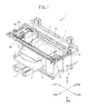
- the printer 1 is an inkjet printer, and configured to inject a liquid ink 97 (see FIG. 2 ) onto a fabric (not shown) such as a T-shirt, which is a printing medium, and print a desired image on the fabric.
- the printing media may be paper or the like.
- the printer 1 injects five different kinds of ink 97 (white, black, yellow, cyan, and magenta) downward to print a color image on the printing medium.
- ink 97 among the five kinds of ink 97 see FIG.
- the white ink is high precipitationability liquid that contains a component precipitating faster than the color ink.
- the component that has high precipitationability is, for example, a pigment such as titanium oxide.
- the white ink is injected onto the fabric, and then the color ink are injected subsequent to the injection of the white ink.
- the white ink is used as, for example, a foundation when printing an image on the fabric that has a dark ground color. It is also possible to use the white ink in a different printing application than injecting the color ink subsequent to injecting the white ink.
- the fabric surface may include an area injected with the white ink only, and an area injected with the color ink only. For a certain image to be printed, the white ink injection may be subsequent to the color ink injection.
- the printer 1 includes a housing 2, a platen drive mechanism 6, a pair of guide rails (not shown), a platen 5, a tray 4, a frame body 10, a guide shaft 9, a rail 7, a carriage 20, head units 100 and 200, a drive belt 101, and a drive motor 19.
- the housing 2 has a substantially rectangular parallelepiped shape that has the longitudinal direction in the right-left direction.
- an operation unit (not shown) for operating the printer 1.
- the operation unit includes a display and operation buttons.
- the display is configured to display various pieces of information. An operator operates the operation buttons when the operator enters commands and instructions in connection with desired movements, motions and actions of the printer 1.
- the frame body 10 has a frame shape, which has a substantially rectangular shape when viewed from the top, and is located on top of the housing 2.
- the frame body 10 supports the guide shaft 9 at its front side, and supports the rail 7 at its rear side.
- the guide shaft 9 is a shaft member that has a shaft portion extending in the right-left direction inside the frame body 10.
- the rail 7 is a rod-shaped member extending in the right-left direction, and located to face the guide shaft 9.
- the carriage 20 can move along the guide shaft 9 in the right-left direction.
- the head units 100 and 200 are arranged in the front-rear direction, and mounted on the carriage 20.
- the head unit 100 is located behind the head unit 200.
- each of the head units 100 and 200 has a head portion 110 at a lower portion thereof.
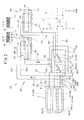
- FIG. 2 and FIG. 3 schematically illustrate the vertical locations of respective elements and members of the flow passages of the inks 97. As such, FIG. 2 and FIG. 3 depict the head units 100 and 200 side by side in the drawing sheets although the head units 100 and 200 are in fact viewed from the front.
- the head portion 110 of the head unit 100 injects the white ink.
- the head portion 110 of the head unit 200 injects the color ink.
- the head portion 110 has a nozzle face 111.
- the nozzle face 111 is a flat surface that is parallel to the horizontal direction, and includes a plurality of fine nozzles 113 (see FIG. 2 ) configured to inject the inks 97 downward.
- the nozzle face 111 defines a bottom face of each of the head units 100 and 200.
- the nozzles 113 are provided in a nozzle arrangement area 120 of the nozzle face 111.
- the nozzle arrangement area 120 is formed in a center area of the nozzle face 111 in the right-left direction, and extends in the front-rear direction.
- the nozzle face 111 has a plurality of nozzle arrays 121-124.
- Each of the nozzle arrays 121-124 is an array of a plurality of nozzles 113.
- Each of the nozzle arrays 121-124 is located in corresponding one of four regions defined by dividing the nozzle arrangement area 120 into four parts in the right-left directions. From the right to the left, there are arranged the nozzle array 121, the nozzle array 122, the nozzle array 123 and the nozzle array 124 in this order.
- Each of the nozzle arrays 121-124 of the head unit 100 can inject the white ink.
- the nozzle arrays 121 and 122 of the head unit 100 are coupled to a single cartridge 301 that reserves the white ink (see FIG. 2 and FIG. 4 ).
- the nozzle arrays 123 and 124 of the head unit 100 are coupled to another cartridge 302 that reserves the white ink (see FIG. 3 and FIG. 4 ).
- each of the nozzle arrays 121-124 of the head unit 200 is coupled to corresponding one of cartridges 303-306 that retain the color inks.
- the nozzle array 121 of the head unit 200 is coupled to the cartridge 303 of the magenta ink (see FIG. 2 and FIG. 4 )
- the nozzle array 122 is coupled to the cartridge 304 of the cyan ink (see FIG. 3 and FIG. 4 )
- the nozzle array 123 is coupled to the cartridge 305 of the yellow ink (see FIG. 2 and FIG. 4 )
- the nozzle array 124 is coupled to the cartridge 306 of the black ink ( FIG. 3 and FIG. 4 ).
- the drive belt 101 has a strip shape spanning in the right-left direction inside the frame body 10.
- the drive belt 101 is flexible, and is made from, for example, synthetic resin.
- the drive motor 19 is provided at the right front area inside the frame body 10, and can rotate in the normal and reverse directions.
- the drive motor 19 is operatively connected to the carriage 20 via the drive belt 101.
- the carriage 20 moves back and forth along the guide shaft 9 in the right-left direction. Accordingly, the head units 100 and 200 move back and forth in the right-left direction, and inject the inks 97 toward the platen 5 that is located below the head units 100 and 200 and faces the head units 100 and 200.
- the platen drive mechanism 6 has a pair of guide rails (not shown) and a platen support (not shown).
- the two guide rails extend in the front-rear direction inside the platen drive mechanism 6, and support the platen support such that the platen support can move in the front-rear direction.
- the platen support is configured to support the platen 5 at an upper portion thereof.
- the platen 5 supports the printing medium.
- the tray 4 is provided below the platen 5.
- the tray 4 supports sleeves of the T-shirt when the operator puts the T-shirt on the platen 5. Thus, the sleeves of the T-shirt do not contact components other than the tray in the housing 2.
- the platen drive mechanism 6 is configured to be driven by a motor (not shown) provided at a rear end of the printer 1.
- the platen drive mechanism 6 is configured to move the platen support and the platen 5 in the front-rear direction of the housing 2 along the paired guide rails. As the platen 5 transports the printing medium in the front-rear direction (sub-scanning direction) and the head portion 110 injects the inks 97 while moving in the right-left direction in the reciprocal manner, the printer 1 prints on the printing medium.
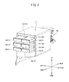
- a mount frame portion 8 shown in FIG. 4 is provided on the right side of the printer 1.
- the mount frame portion 8 is supported by the housing 2 (not shown in FIG.4 ).
- the mount frame portion 8 has a plurality of mount portions 80, and each of the mount portions 80 is configured to mount the cartridge 3.
- Each mount portion 80 is a recess that has a rectangular parallelepiped shape, and is concave in the rear direction from the front face of the mount frame portion 8.
- the inner rear end of each mount portion 80 has a hollow needle (not shown) extending toward the front.
- the hollow needle sticks in a rubber lid (not shown) provided at a mouth plug 70 (see FIG. 5 ) of a liquid container 31 received in the cartridge 3.
- the hollow needle draws out the ink 97 from the liquid container 31 (see FIG. 5 ) held in the cartridge 3.
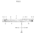
- the cartridge 3 has a casing 32, the liquid container 31, a shaft 43, and a resilient member 45.
- the casing 32 is a rectangular parallelepiped, which is generally elongated in the front-rear direction.
- the casing 32 has an opening 321 at its rear end.
- the liquid container 31 is located in the casing 32.
- the liquid container 31 has a liquid bag 13 and the mouth plug 70.
- the liquid bag 13 is a bag-like container formed by placing rectangular flexible sheets 13A and 13B one after another, which are made from synthetic resin or the like, such that one face of one of the sheets faces one face of the other sheet, and heating and fusing the peripheries of the two sheets (by means of thermal seal) to connect the two sheets 13A and 13B to each other.
- the liquid bag 13 extends in the front-rear direction.
- the mouth plug 70 is attached to the rear end of the liquid bag 13, and is exposed rearward from the opening 321 of the casing 32.
- the mouth plug 70 is a cylindrical element extending in the rear direction, and a rubber plug (not shown) located in the mouth plug 70 provides a seal such that the ink 97 in the liquid bag 13 does not leak.
- the shaft 43 has a cylindrical shape extending in the right-left direction.
- the shaft 43 has projections (not shown) at right and left ends thereof such that the projections project outwardly in the right and left directions respectively.
- the projections are located in recesses 53 provided at right and left side faces in the casing 32.
- the recesses 53 are depressed outwardly in the right and left directions, respectively, and extend in the front-rear direction.
- the resilient member 45 extend on the bottom face in the front-rear direction inside the casing 32. A rear end of the resilient member 45 is secured to a rear portion of the casing 32, and a front end of the resilient member 45 is wound around the shaft 43 such that the resilient member 45 biases the shaft 43 and exerts a returning force in the rear direction.
- the shaft 43 winds up the liquid bag 13 and collects the ink 97 toward the mouth plug 70 as the shaft 43 moves in the rear direction.
- the shaft 43 moves in the rear direction as the remaining amount of ink 97 in the liquid container 31 decreases (see the arrow 39 in FIG. 5 ).
- the ink 97 is supplied to the nozzle face 111 from the cartridge 3 engaged in the mount portion 80.
- a region in the up-down direction is referred to as a first region 211.
- the first region 211 is a region in which a distance from the nozzle face 111 in the up-down direction is out of a predetermined range.
- a region in the up-down direction is referred to as a second region 212.
- the second region 212 is a region in which a distance from the nozzle face 111 in the up-down direction is in the predetermined range.
- the predetermined range is a range in which a distance measured from the nozzle face 111 in the downward direction falls within a range between the distances L1 and L2.
- L1 is 10 mm and L2 is 50 mm.
- a meniscus is created at the nozzle face 111 by the surface tension, i.e., the ink 97 is concave in the nozzle 113. The meniscus holds the ink 97 at the nozzle face 111.
- the ink 97 When the ink 97 is supplied toward the nozzle face 111 from the second region 212, which is the predetermined range apart from the nozzle face 111 by the predetermined distance in the up-down direction, the meniscus is difficult to break, and it is possible to properly inject the ink 97.
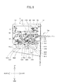
- the mount portions 80 are arranged in two columns side by side in the right-left direction and in three tiers in the up-down direction.
- the mount portions 80 includes first mount portions 811-814 located in the first region 211, and second mount portions 821 and 822 located in the second region 212.
- the second mount portions 821 and 822 are located below the first mount portions 811-814.
- the second mount portion 821 is located at the lower right area of the mount frame portion 8, and the second mount portion 822 is located on the left of the second mount portion 821.
- the first mount portions 811 and 812 are located above the second mount portions 821 and 822, respectively, and the first mount portions 813 and 814 are located above the first mount portions 811 and 812, respectively.
- the second mount portions 821 and 822 can mount the cartridges 301 and 302, respectively.
- Each of the cartridges 301 and 302 contains the white ink, which is the high precipitationability liquid.
- the first mount portions 811-814 can mount the cartridges 303-306, respectively.
- the cartridges 303-306 contain the color inks.
- FIG. 7 and FIG. 8 four sub-tanks 91 and four sub-tank supports 92 are provided behind the mount frame portion 8.
- the sub-tanks 91 and the sub-tank supports 92 are located such that they face the second mount portions 821 and 822 in the horizontal direction.
- the sub-tanks 91 are located in the second region 212.
- FIG. 2 and FIG. 3 schematically show the positions of the respective members of the flow passage of the ink 97 in the up-down direction.
- the directions of the sub-tank(s) 91 and the sub-tank support(s) 92 may be different from the directions shown in FIG. 7 .
- the sub-tanks 91 define reservoir passages 711-714, which will be described later (see FIG. 2 and FIG. 3 ), and can reserve the ink 97 to be supplied to the nozzle face 111 from the cartridge 3.
- the sub-tank 91 has a bag 93 and mouth plugs 941 and 942.
- the reference numerals of the bag 93 and the mouth plugs 941 and 942 are only shown for the sub-tank 911 (will be described).
- the bag 93 is a bag-shaped container formed by folding a rectangular-shaped flexible sheet made from a material such as synthetic resin and jointing the peripheries of the peripheral portions of the folded sheet by heating and fusing (by means of thermal seal) to provide the bag.
- the bag 93 may be a bag-like container formed by placing rectangular flexible sheets one after another, which are made from synthetic resin or the like, such that one face of one of the sheets faces one face of the other sheet, and heating and fusing the peripheries of the two sheets (by means of thermal seal) to connect the two sheets to each other.
- the mouth plug 941 is provided at one end in the longitudinal direction of the bag 93.
- the mouth plug 942 is provided at the other end in the longitudinal direction of the bag 93.
- the sub-tank support 92 is a member to support the sub-tank 91. As shown in FIG. 7 , the sub-tank support 92 has a support plate portion 95 and a valve portion 961. In FIG. 7 , the reference numerals of the support plate portion 95 and the valve portion 961 are only shown for the sub-tank support 921, which will be described later.
- the support plate portion 95 is a plate-like member, and supports the sub-tank 91 on its upper face.
- the valve portion 961 is located at the right end of the support plate portion 95, and connects to any of the first connection passages 621-624 (will be described later) and to the mouth plug 941 of the sub-tank 91.
- the support plate portion 14 is provided on the back face 81 of the mount frame portion 8.
- the support plate portion 14 supports the sub-tank support 92.
- the support plate portion 14 has a first plate portion 141, a second plate portion 142, and a third plate portion 143.
- the first plate portion 141 extends rearward from a right end of the rear face 81 of the mount frame portion 8 in the right-left direction, between the first mount portions 811, 812 and the second mount portions 821, 822 in the up-down direction and.
- the second plate portion 142 connects to the rear end of the first plate portion 141 and extends in the right-left direction.
- the second plate portion 142 is situated behind the mount frame portion 8.
- the third plate portion 143 extends in the right-left direction behind the second plate portion 142.
- the lower right end of the third plate portion 143 is coupled to the lower right end of the second plate portion 142 by a plate element (not shown) extending in the front-rear direction.
- the left end of the support plate portion 14 is supported by a frame member (not shown).
- the four sub-tank supports 92 and the four sub-tanks 91 are arranged in two columns side by side in the right-left direction and in two tiers in the front-rear direction.
- the four sub-tanks 91 are assigned reference numerals 911, 912, 913 and 914, respectively (i.e., sub-tanks 911-914), in the following description.
- the four sub-tank supports 92 for supporting the four sub-tanks 911-914 are assigned reference numerals 921, 922, 923 and 924 (sub-tank supports 921-924), respectively.
- the sub-tank 913 and the sub-tank support 923 are situated behind the second mount portion 821 (see FIG. 6 ).
- the sub-tank 914 and the sub-tank support 924 are situated behind the second mount portion 822 (see FIG. 6 ).
- the sub-tank supports 923 and 924 connect to the second plate portion 142 of the support plate 14.
- the sub-tank 911 and the sub-tank support 921 are situated behind the sub-tank 913 and the sub-tank support 923.
- the sub-tank 912 and the sub-tank support 922 are situated behind the sub-tank 914 and the sub-tank support 924.
- the third plate portion 143 of the support plate 14 is situated behind the sub-tank supports 923 and 924.
- the sub-tank supports 921 and 922 connect to the third plate 143, respectively.
- the sub-tank 91 and the sub-tank support 92 incline to the diagonally upward left direction relative to the horizontal plane.
- a pump support 15 is attached to the back face 81 of the mount frame portion 8.
- the pump support 15 supports the pumps 901-904 (see FIG. 9 ).
- the pump support 15 has a pair of first support plate portions 151 and a second support plate portion 152.
- the pair of the first support plate portions 151 respectively extend rearward from the right and left ends of the back face 81 of the mount frame portion 8 in the right-left direction, above the first mount portions 813 and 814.
- the second support plate portion 152 connects to the rear lower ends of the pair of the first support plate portions 151, and extends in the right-left direction.
- the second support plate portion 152 is generally parallel to the horizontal direction.
- the four pumps 901-904 connect to the bottom face of the second support plate portion 152 of the pump support 15, and are arranged in the left direction from the right side. Thus, the four pumps 901-904 are situated behind the mount frame portion 8. In FIG. 9 , fluid passages that connect the pumps 901-904 to the head portion 110 are not shown.
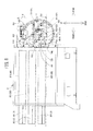
- the ink passage arrangement 700 will be described. As shown in FIG. 2 and FIG. 3 , the ink passage arrangement 700 has reservoir passages 711-714 and non-reservoir passages 72A, 72B.
- FIG.2 illustrates the fluid passages which are connected to the first mount portions 811 and 813 and the second mount portion 821 on the right column in FIG. 6 .
- FIG. 3 illustrates the fluid passages which are connected to the first mount portions 812 and 814 and the second mount portion 822 on the left column in FIG. 6 .
- the reservoir passages 711-714 are fluid passages that connect the first mount portions 811-814 to the head portion 110 of the head unit 200, respectively.
- the reservoir passages 711-714 have sub-tanks 911-914, respectively.
- the non-reservoir passages 72A and 72B are fluid passages that connect the second mount portions 821 and 822 to the head portion 110 of the head unit 100, respectively.
- the non-reservoir passages 72A and 72B do not have sub-tanks 911-914.
- the non-reservoir passages 72A and 72B are fluid passages through which the white ink (i.e., the high precipitationability fluid) flows.
- the reservoir passages 711-714 include fluid feed ports 611-614, first connection passages 621-624, second connection passages 631-634, and sub-tanks 911-914, respectively.
- the fluid feed ports 611-614 are provided behind the first mount portions 811-814 at the rear face 81 of the mount frame portion 8, respectively.
- the fluid feed ports 611-614 connect to the hollow needles (not shown) provided in the first mount portions 811-814 via fluid passages (not shown), respectively.
- the fluid feed ports 611-614 feed the ink 97 to the head portion 110 from the first mount portions 811-814.
- each of the first connection passages 621-624 connects to the associated fluid feed port 611, 612, 613, 614.
- the first connection passages 621-624 extend to the sub-tanks 911-914 located in the second region 212, respectively.
- the other end of each of the first connection passages 621-624 connects to a valve portion 961 (see FIG. 7 ) of the associated sub-tank support 921, 922, 923, 924, and in turn to the mouth plug 941 of the associated sub-tank 911, 912, 913, 914.
- the valve portion 961 has a fluid passage that connects the associated first connection passage 621, 622, 623, 624 to the corresponding mouth plug 941.
- the valve portion 961 is equipped with a solenoid valve (not shown), and the solenoid valve opens and closes the fluid passage, which extends from the associated first connection passage 621, 622, 623, 624 to the corresponding mouth plug 941, under the control of a CPU (not shown). Accordingly, the printer 1 can adjust an amount of the ink 97 to be introduced into the sub-tank 91.
- each of the second connection passages 631-634 connects to the mouth plug 942 of the associated sub-tank 911, 912, 913, 914.
- the other end of each second connection passage 631, 632, 633, 634 connects to the head portion 110 of the head unit 200, and in turn to the associated nozzle array 121, 122, 123, 124 of the nozzle face 111 (see FIG. 2 and FIG. 3 ).
- the non-reservoir passage 72A has the liquid feed port 73A, a common passage 74A, branch passages 751A and 752A, filter portions 681A and 682A, a first branch portion 753A, second branch portions 791A and 792A, and feed passages 761A and 762A.
- Circulation passages 771A and 772A connect to the non-reservoir passage 72A.
- the liquid feed port 73A is provided behind the second mount portion 821 at the rear face 81 of the mount frame portion 8.
- the liquid feed port 73A connects to the hollow needle provided in the second mount portion 821 via a fluid passage (not shown).
- the liquid feed port 73A feeds the ink 97 to the head portion 110 from the second mount portion 821.
- the common passage 74A connects to the liquid feed port 73A, and extends in the rear direction toward the sub-tank 91 from the second mount portion 821.
- the branch passages 751A and 752A connect to the rear end of the common passage 74A.
- the branch portion of the common passage 74A that branches to the branch passages 751A and 752A is referred to as a first branch portion 753A (see FIG. 2 and FIG. 11 ).
- the first branch portion 753A is situated between the second mount portion 821 and the sub-tank 913.
- the branch passage 751A extends to the right from the first branch portion 753A.
- the first branch portion 753A defines a bend portion that bends in the right direction and that is formed on the non-reservoir passage 72A.
- the right direction crosses the rear direction extending from the second mount portion 821 to the sub-tank 91.
- the branch passage 752A extends to the left from the first branch portion 753A.
- the first branch portion 753A defines a bend portion that bends in the left direction and that is formed on the non-reservoir passage 72A.
- the left direction crosses the rear direction extending from the second mount portion 821 to the sub-tank 91.
- the feed passage 761A and the circulation passage 771A connect to the right end of the branch passage 751A.
- the branch portion of the branch passage 751A that branches to the feed passage 761A and the circulation passage 771 A is referred to as a second branch portion 791 A.
- the filter portion 681A is provided at a fluid passage between the second mount portion 821 and the second branch portion 791 A. In this embodiment, the filter portion 681A is provided at the branch passage 751A.
- the filter portion 681A has a disk shape.
- the filter portion 681A possesses a higher passage resistance than a passage resistance of the circulation passage 771 A.
- the filter portion 681A reduces the possibility of foreign matters, which is contained in the ink 97, flowing to the downstream. This is also true to filter portions 682A, 681B and 682B (will be described later).
- the feed passage 761A extends upward from the second branch portion 791A.
- the second branch portion 791A defines a bend portion that bends in the up direction crossing the right direction at the non-reservoir passage 72A.
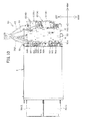
- the feed passage 761 A extends upward from the second branch portion 791 A, and then bends to the left at the bend portion 781A (see FIG. 7 and FIG. 10 ).
- the feed passage 761A connects to the head portion 110 of the head unit 100, and in turn to the nozzle 113 arranged in the nozzle array 121. As shown in FIG.
- the second branch portion 791A and the bend portion 781A are provided on the non-reservoir passage 72A at positions closer to the head portion 110 than the first branch portion 753A (see FIG. 11 ), i.e., provided on the downstream side, such that the second branch portion 791A and the bend portion 781A are situated between the mount portion 80 and the sub-tank 91 in the horizontal direction.
- the circulation passage 771A is a fluid passage through which the white ink, i.e., the high precipitationability liquid from the non-reservoir passage 72A, circulates.
- the diameter of the circulation passage 771 A is smaller than the diameter of the non-reservoir passage 72A.
- one end of the circulation passage 771A connects to the feed passage 761A of the non-reservoir passage 72A at the second branch portion 791A, and the other end of the circulation passage 771 A connects to the feed passage 761 A at the head unit 100.
- the second branch portion 791A is situated closer to the second mount portion 821 than the head unit 100.
- the pump 904 (see FIG. 9 ) is provided on the circulation passage 771A, and the white ink (i.e., high precipitationability liquid) is caused to circulate through the non-reservoir passage 72A (feed passage 761A) as the pump 904 is activated.
- the circulation passage 771A extends downward from the second branch portion 791A, and then extends below and behind the sub-tank 91 and the sub-tank support 92.
- the circulation passage 771A then extends to the head unit 100 via the pump 904 (see FIG. 9 ). As such, part of the circulation passage 771A is situated below the sub-tank 91.
- the feed passage 762A and the circulation passage 772A connect to the left end of the branch passage 752A.
- the filter portion 682A is provided on the branch passage 752A.
- the filter portion 682A has a disk shape.
- the filter portion 682A has a higher passage resistance than a passage resistance of the circulation passage 772A.
- the feed passage 762A extends upward from the second branch portion 792A.
- the second branch portion 792A defines a bend portion that bends in the up direction crossing the left direction at the non-reservoir passage 72A.
- the feed passage 762A extends upward from the second branch portion 792A, and then bends to the left at the bend portion 782A (see FIG. 10 ).
- the feed passage 762A connects to the head portion 110 of the head unit 100, and in turn to the nozzle 113 arranged in the nozzle array 122.
- the second branch portion 792A and the bend portion 782A are provided on the non-reservoir passage 72A at positions closer to the head portion 110 than the first branch portion 753A, i.e., on the downstream side.
- the second branch portion 792A and the bend portion 782A are situated between the mount portion 80 and the sub-tank 91 in the horizontal direction.
- the circulation passage 772A is a fluid passage through which the white ink, i.e., the high precipitationability liquid from the non-reservoir passage 72A, circulates.
- the diameter of the circulation passage 772A is smaller than the diameter of the non-reservoir passage 72A.
- one end of the circulation passage 772A connects to the feed passage 762A of the non-reservoir passage 72A at the second branch portion 792A, and the other end of the circulation passage 772A connects to the feed passage 762A at the head unit 100.
- the pump 903 (see FIG. 9 ) is provided on the circulation passage 772A, and the white ink, i.e., the high precipitationability liquid, circulates in the non-reservoir passage 72A (feed passage 762A) as the pump 903 is activated.
- the circulation passage 772A extends downward from the second branch portion 792A, and then extends below and behind the sub-tank 91 and the sub-tank support 92.
- the circulation passage 772A then extends to the head unit 100 via the pump 903 (see FIG. 9 ). As such, part of the circulation passage 772A is situated below the sub-tank 91.
- the second branch portion 792A is situated closer to the second mount portion 821 than the head unit 100.
- the non-reservoir passage 72B has a liquid feed port 73B, a common passage 74B, branch passages 751B and 752B, filter portions 681B and 682B, a first branch portion 753B, second branch portions 791B and 792B, and feed passages 761B and 762B.
- the circulation passages 771B and 772B are connected to the non-reservoir passage 72B.
- the non-reservoir passage 72B has bend portions 781B and 782B that are similar to the bend portions 781A and 782A.
- the feed passages 761B and 762B extend upwards, and then bends to the left to define the bend portions 781B and 782B.
- the liquid feed port 73B feeds the ink 97 to the head portion 110 from the second mount portion 822.
- the feed passages 761B and 762B connect to the nozzle arrays 123 and 124 of the head unit 100, respectively.
- the liquid feed port 73B feeds the ink 97 to the head portion 110 from the second mount portion 822.
- the pumps 901 and 902 are provided on the circulation passages 772B and 771B, respectively.
- the filter portions 681B and 682B have higher passage resistances than the passage resistances of the circulation passages 771B and 772B, respectively.
- the flow of the ink 97 when a printing operation, which injects the ink 97 from the nozzle face 111 for printing, is carried out and a circulating operation, which drives the pumps 901-904 to circulate the white ink (i.e., high precipitationability liquid), is carried out will be described.
- the printing operation and the circulating operation are carried out as the CPU (not shown) of the printer 1 controls the printer 1 in accordance with a control program stored in a storage unit (not shown).
- the ink 97 is injected from the nozzle 113 of the nozzle face 111 as a piezo-electric device (not shown) provided at the heat part 110 is activated.
- the movement of the ink 97 injected from the nozzle 113 serves as a pumping force, which pulls the ink 97 toward the nozzle face 111.
- the white ink is supplied to the nozzle array 121 of the head unit 100 from the cartridge 301 through the liquid feed port 73A, the common passage 74A, the branch passage 751A and the feed passage 761A.
- the white ink is supplied to the nozzle array 122 of the head unit 100 from the cartridge 301 through the liquid feed port 73A, the common passage 74A, the branch passage 752A and the feed passage 762A.
- the white ink is supplied to the nozzle array 123 of the head unit 100 from the cartridge 302 through the liquid feed port 73B, the common passage 74B, the branch passage 751B and the feed passage 761B.
- the white ink is supplied to the nozzle array 124 of the head unit 100 from the cartridge 302 through the liquid feed port 73B, the common passage 74B, the branch passage 752B and the feed passage 762B.
- the color ink is supplied to the nozzle arrays 121-124 of the head unit 200 from the cartridges 303-306 via the first connection passages 621-624, the valve portion 961, the sub-tanks 911-914 and the second connection passages 631-634, respectively. Because the pumps 901-904 are not activated during the printing, the white ink does not flow in the circulation passages 771A, 772A, 771B and 772B.
- the meniscus is created on the nozzle face 111 (i.e., the ink 97 makes a recess in the nozzle 113) due to the surface tension when the printing is completed.
- the meniscus holds the ink 97 on the nozzle face 111.
- the circulating operation will be described.
- the pumps 901-904 are activated during a no printing time (i.e., while the ink 97 is not being injected from the nozzle 113) under the control of the CPU to perform the circulating operation.
- the ink 97 is circulated through the feed passages 761A, 762A, 761B and 762B and the circulation passages 771A, 772A, 771B and 772B. This generates the stirring of the white ink, which is the high precipitationability fluid.
- the printer 1 of this embodiment has the above-described configuration.
- the second mount portions 821 and 822 and the sub-tanks 91 are located in the second region 212.
- the head difference of the ink 97 based on the position of the sub-tanks 91 and the position of the nozzle face 111 becomes substantially equal to the head difference of the ink 97 based on the position of the second mount portions 821, 822 and the position of the nozzle face 111.
- the meniscus properly holds the ink 97 on the nozzle face 111, and insufficient injection of the ink 97 becomes difficult to occur. As such, it is possible to reduce the possibility of printing quality deterioration.
- the sub-tanks 91 incline diagonally relative to the horizontal plane, and the upper ends of the sub-tanks 91 are situated slightly above the second region 212, but the head of the ink 97 in the sub-tanks 91 is in the second region 212.
- the shaft 43 shown in FIG. 5 is biased in the rear direction by the resilient member 45, and winds up the liquid bag 13.
- the pressure for expelling the ink 97 from the liquid bag 13 is greater than the pressure when there are no resilient member 45 and the shaft 43.
- the head of the ink 97 within the liquid container 31 in the cartridge 301, 302 is above the second mount portion 821, 822, but is in the second region 212.
- the non-reservoir passages 72A and 72B do not have the sub-tanks 91.
- some of the fluid passages extending to the head portion 110 from the respective mount portions 80 are only equipped with the sub-tanks 91.
- the cartridges 301 and 302, which contain the white ink or the high precipitationability liquid, are mounted in the second mount portions 821 and 822, which connect to the non-reservoir passages 72A and 72B. Because the non-reservoir passages 72A and 72B have no sub-tanks 91, it is possible to prevent the white ink component, which has the high precipitationability, from remaining in the sub-tanks 91, and prevent the concentration of the white ink component injected from the nozzle 113 from decreasing. Accordingly, it is possible to reduce the possibility of printing quality deterioration.
- the white ink component having the high precipitationability becomes difficult to precipitate in the non-reservoir passages 72A and 72B. It is, therefore, possible to reduce the possibility that the white ink component injected from the nozzle 113 would have a reduced concentration, and reduce the possibility of printing quality deterioration.
- the movement of the ink 97 injected from the nozzle 113 serves as a pumping force that pulls the ink 97 toward the nozzle face 111, and the ink 97 is supplied to the nozzle face 111.
- the pumps 901-904 are activated during the printing, the pressure exerted by the pumps 901-904 applies to the ink 97, and the ink 97 may not be injected appropriately.
- the pumps 901-904 are activated while the printing is not being carried out, i.e., while the ink 97 is not being injected from the nozzle 113.
- the white ink i.e., the high precipitationability liquid, is circulated from the non-reservoir passages 72A and 72B.
- the pumps 901-904 are not activated during the printing, and the ink 97 is injected appropriately. Because the pumps 901-904 are activated during the no printing time to stir the white ink, the white ink component is difficult to precipitate in the non-reservoir passages 72A and 72B. Thus, it is possible to reduce the possibility that the white ink component injected from the nozzle 113 would have a reduced concentration, and to reduce the possibility that the printing quality would be deteriorated.
- each of the circulation passages 771A, 772A, 771B and 772B is smaller than the diameter of each of the non-reservoir passages 72A and 72B. Therefore, it is possible to reduce the possibility that the circulation passages 771A, 772A, 771B and 772B would interfere with other fluid passages, as compared to a configuration that the diameter of each of the circulation passages 771A, 772A, 771B and 772B is greater than the diameter of each of the non-reservoir passages 72A and 72B.
- the circulation passages 771A, 772A, 771B and 772B are equipped with the pumps 901, 902, 903 and 904, respectively, it is possible to circulate the white ink even if the diameter of each of the circulation passages 771A, 772A, 771B and 772B is smaller than the diameter of each of the non-reservoir passages 72A and 72B. Because the non-reservoir passages 72A and 72B have appropriate diameters, it is possible to properly feed the white ink to the nozzle face 111. Thus, it is possible to reduce the possibility of the deterioration in the printing quality.
- the circulation passages 771A, 772A, 771B and 772B are easy to bend.
- the freedom with regard to the piping increases.
- the non-reservoir passages 72A and 72B bend in a direction that crosses the rear direction heading to the sub-tanks 91 from the second mount portions 821 and 822 (see FIG. 2 , FIG. 8 and FIG. 3 ) at the first branch portions 753A and 753B, respectively.
- the printer 1 can be downsized.
- the second branch portions 791 A, 792A, 791B and 792B and the bend portions 781 A, 782A, 781B and 782B are located closer to the head portion 110 than the first branch portions 753A and 753B (i.e., situated on the downstream side) in the non-reservoir passages 72A and 72B, and bend at positions between the mount portions 80 and the sub-tanks 91 in the horizontal direction.
- the non-reservoir passages 72A and 72B have more bend portions.
- the non-reservoir passages 72A and 72B by means of the second branch portions 791A, 792A, 791B and 792B and the bend portions 781A, 782A, 781B and 782B, and avoid the reservoir passages 711-714 extending from the mount portions 80 when locating the non-reservoir passages 72A and 72B. Therefore, it is possible to reduce the possibility of interference between the reservoir passages 711-714 and the non-reservoir passages 72A and 72B.
- non-reservoir passages 72A and 72B fluid passages from the second mount portions 821 and 822 to the second branch portions 791A, 792A, 791B and 792B are present outside the area of connections of the circulation passages 771A, 772A, 771B and 772B.
- stirring of the high precipitationability liquid is difficult to occur between the second mount portions 821 and 822 and the second branch portions 791 A, 792A, 791B and 792B.
- the second branch portions 791A, 792A, 791B and 792B are located closer to the second mount portions 821 and 822 than the head unit 100.
- the second branch portions 791A, 792A, 791B and 792B are located between the mount portions 80 and the sub-tanks 91 in the horizontal direction.
- the filter portions 681A, 682A, 681B and 682B have higher passage resistances than the circulation passages 771A, 772A, 771B and 772B, respectively.
- the white ink that is present downstream of the filter portions 681 A, 682A, 681B and 682B tends to flow in the circulation passages 771 A, 772A, 771B and 772B rather than in the filter portions 681A, 682A, 681B and 682B.
- the white ink tends to flow in the circulation passages 771 A, 772A, 771B and 772B upon stirring of the white ink with the pumps 901-904, and the white ink is difficult to flow back toward the second mount portions 821 and 822, as compared to a configuration having no filter portions 681A, 682A, 681B and 682B.
- the second mount portions 821 and 822 and the sub-tanks 91 are provided in the second region 212. If the second mount portions 821 and 822 are located above the first mount portions 811-814, then the sub-tanks 91 would be situated above the first mount portions 811-814. Thus, pumps are required to pull up the ink 97 to the sub-tanks 91 from the first mount portions 811-814. In this embodiment, the second mount portions 821 and 822 are located below the first mount portions 811-814, and therefore the sub-tanks 91 are situated below the first mount portions 811-814. Thus, the gravity can be used to feed the ink 97 to the sub-tanks 91 from the first mount portions 811-814. Accordingly, it is not necessary to provide pumps to feed the ink 97 to the sub-tanks 91, and it is possible to reduce the number of parts.
- the second mount portions 821 and 822 are located below the first mount portions 811-814. If the circulation passages 771A, 772A, 771B and 772B are located above the sub-tanks 91, then the first connection passages 621-624 extending to the sub-tanks 91 from the first mount portions 811-814 tend to interfere with the circulation passages 771A, 772A, 771B and 772B. In this embodiment, certain part of the circulation passages 771A, 772A, 771B and 772B are located below the sub-tanks 91.
- first connection passages 621-624 extending to the sub-tanks 91 from the first mount portions 811-814 are difficult to interfere with the circulation passages 771A, 772A, 771B and 772B. Otherwise the reservoir passages 711-714 would interfere with the non-reservoir passages 72A and 72B and the fluid passages would bend such that feeding the ink 97 to the nozzle face 111 would become difficult. As such, it is possible to reduce the possibility of the printing quality deterioration.
- the printer 1 is an example of the "print device” of the present invention.
- the cartridge 3 is an example of the “container” of the present invention.
- the sub-tank 91 is an example of the "reservoir” of the present invention.
- Each of the cartridges 301 and 302 for containing the high precipitationability liquid is an example of "high precipitationability liquid container” of the present invention.
- the pumps 901-904 are examples of the "pump" of the present invention.
- the rear direction is an example of the "first direction” of the present invention.
- the direction crossing the rear direction (e.g., the left direction and the right direction) is an example of the "second direction” of the present invention.
- Each of the first branch portions 753A and 753B, at which the fluid passage bends, is an example of the "first bend portion” of the present invention.
- Each of the second branch portions 791A, 792A, 791B and 792B, at which the fluid passage bends, is an example of the "second bend portion” of the present invention, and each of the bend portions 781A, 782A, 781B and 782B, at which the fluid passage bends, is also an example of the "second bend portion” of the present invention.
- Each of the second branch portions 791 A, 792A, 791B and 792B, at which the fluid passage is branched is an example of the "branch portion" of the present invention.
- the present invention is not limited to the above-described embodiment, and various changes and modifications may be made to the above-described embodiment.
- the high precipitationability liquid may be another liquid as long as the liquid includes a component that has higher precipitationability than the liquid contained in the cartridges 303-304 to be mounted in the first mount portions 811-814.
- the liquid to be injected from the nozzle face 111 is not limited to the ink 97.
- the liquid to be injected from the nozzle face 111 may be a discharge printing agent for decoloring a dyed fabric.
- One of the non-reservoir passages 72A and 72B may only be provided.
- each circulation passage 771A, 772A, 771B, 772B is located below the associated sub-tank 91, that part of the circulation passage may be located at a position other than below the associated sub-tank.
- a certain part of the circulation passage 771A, 772A, 771B, 772B may be located on the right or left of the sub-tank 91.
- the second mount portions 821 and 822 are located below the first mount portions 811-814, the present invention is not limited in this regard.
- the second mount portions 821 and 822 may be located above the first mount portions 811-814. In this configuration, the first mount portions 811-814 are located in the first region 211 (see FIG.
- the second branch portions 791A, 792A, 791B and 792B are provided between the mount portions 80 and the sub-tanks 91 in the horizontal direction. It should be noted, however, that the second branch portions 791A, 792A, 791B and 792B may be provided at positions other than between the mount portions 80 and the sub-tanks 91 in the horizontal direction. For example, the second branch portions 791A, 792A, 791B and 792B may be provided closer to the head unit 100 than the second mount portions 821 and 822.
- the second branch portions 791A, 792A, 791B and 792B and the bend portions 781A, 782A, 781B and 782B, at which the non-reservoir passages 72A and 72B bend, are provided on the downstream side (i.e., closer to the head portion 110 than the first branch portions 753A and 753B) in the above-described embodiment, but the present invention is not limited in this regard. It is only necessary to provide at least one bend portion on the non-reservoir passage 72A, 72B, which is situated on the downstream side (closer to the head portion 110 than the first branch portions 753A, 753B). One bend portion or three or more bend portions may be provided on the non-reservoir passage 72A, 72B.
- the second branch portions 791 A, 792A, 791B and 792B and the bend portions 781A, 782A, 781B and 782B are situated between the mount portions 80 and the sub-tanks 91 in the horizontal direction
- the second branch portions 791 A, 792A, 791B and 792B and the bend portions 781A, 782A, 781B and 782B may be situated at positions other than between the mount portions 80 and the sub-tanks 91.
- the first branch portions 753A and 753B having a bending shape may be omitted.
- the pumps 901-904 may be activated during the print time, i.e., while the ink 97 being injected from the nozzle 113, to circulate the high precipitationability liquid from the non-reservoir passages 72A and 72B.
- Electromagnetic valves may be provided on the feed passages 761 A, 762A, 761B and 762B immediately before connecting to the nozzle face 111, and the pumps 901-904 may be activated with the electromagnetic valves being closed, to circulate the high precipitationability liquid.
- the circulation passages 771A, 772A, 771B and 772B and the pumps 901-904 may be omitted.
- the bend portions that bend toward the feed passages 761A, 762A, 761A and 762B may only be provided at the second branch portions 791A, 792A, 791B and 792B.
- the second branch portions 791 A, 792A, 791B and 792B may be omitted.
- the cartridges 301 and 302, which carry the high precipitationability liquid therein, are located at the second mount portions 821 and 822 in the above-described embodiment. It should be noted, however, that the cartridge 3 for carrying the liquid that contains a component having the same precipitationability as (or a smaller precipitationability than) the ink 97, which is carried in the cartridges 303-306 mounted in the first mount portions 811-814, may be located at the second mount portions 821 and 822. Although the cartridge 3 has the shaft 43 and the resilient member 45 in the above-described embodiment (see FIG. 5 ), the cartridge 3 may have no shaft 43 and no resilient member 45.
- the filter portions 681 A, 682A, 681B and 682B may be omitted.
Landscapes
- Ink Jet (AREA)
Abstract
Description
- The present invention relates to a print device.
- There is known a print device that includes a plurality of mount portions for mounting ink cartridges. The print device has a head for injecting an ink onto a printing medium. The head includes a nozzle face that has a nozzle configured to inject the ink. The mount portions are located in the horizontal direction or the vertical direction (see, for example, Japanese Patent Application Laid-Open Publication No.
2012-96422 1999-115203 - The nozzle face holds the ink with the meniscus created by the surface tension of the ink. If there is no sub-tank on a fluid passage between the mount portion and the nozzle surface and the mount portions are arranged in the horizontal direction, the head difference between the nozzle face and one mount portion becomes equal to the head difference between the nozzle face and any one of the remaining mount portions, and the ink holding by means of the meniscus becomes appropriate. However, the length of the print device becomes long in the horizontal direction. When the mount portions are arranged in the vertical direction, the length of the print device becomes short in the horizontal direction, but the head differences between the nozzle face and the respective mount portions are different from one mount portion to another mount portion. If the head difference between a cartridge mounted in the mount portion and the nozzle face falls outside a prescribed range, the meniscus on the nozzle face is destroyed. This may cause defective ink injection, and reduce the printing quality.
- When the mount portions are arranged in the vertical direction and the sub-tanks are arranged in the horizontal direction, the head differences between the nozzle face and the respective sub-tanks are equal to each other. Consequently, it is possible to reduce the possibility of defective injection. However, if all the fluid passages (channels) are provided with the sub-tanks, then a problem arises, i.e., the number of parts increases.
- An object of the present invention is to provide a print device that can reduce the number of parts and also reduce the possibility of printing quality deterioration.
- A print device of the present invention includes a head having a nozzle face, and the nozzle face has a nozzle for injecting liquid. The print device also includes a plurality of mount portions arranged in an up-down direction. Each of the mount portions is configured to mount each of a plurality of containers, and each of the plurality of the containers is configured to contain the liquid. The plurality of the mount portions include a first mount portion located in a first region. The first region is a region in which a distance from the nozzle face in the up-down direction is out of a predetermined range. The plurality of the mount portions also include a second mount portion located in a second region. The second region is a region in which a distance from the nozzle face in the up-down direction is in the predetermined range. The print device also includes a reservoir passage configured to connect the first mount portion to the head. The reservoir passage has a reservoir located in the second region. The reservoir is configured to reserve the liquid. The print device also includes a non-reservoir passage configured to connect the second mount portion to the head. The non-reservoir passage has no reservoir.
- Because the reservoir is provided in the second region, the head difference of the liquid based on the position of reservoir and the position of the nozzle face becomes substantially equal to the head difference of the liquid based on the position of the second mount portion and the position of the nozzle face. Therefore, the meniscus holds the ink properly on the nozzle face, and the defective ink injection is unlikely to occur. Accordingly, it is possible to reduce the possibility of printing quality deterioration.
- No reservoir is provided on the non-reservoir passage. In other words, the reservoir(s) is (are) provided on a part of the plurality of fluid passages extending to the head from the mount portions. Thus, it is possible to reduce the number of parts, as compared to a configuration having the reservoirs on all the fluid passages extending to the head from the mount portions.
- The second mount portion may be configured to mount a high precipitationability liquid container containing high precipitationability liquid. The high precipitationability liquid may include a component having higher precipitationability than the liquid contained in the container mounted at the first mount portion.
- No reservoir is provided on the non-reservoir passage connecting the second mount portion to the head. It is possible to prevent a component of the high precipitationability liquid from staying in the reservoir, and prevent the component of the high precipitationability liquid injected from the nozzle from having a reduced concentration. Thus, it is possible to reduce the possibility of printing quality deterioration.
- The print device may further include a circulation passage connected to the non-reservoir passage and a pump. The high precipitationability liquid from the non-reservoir passage circulates in the circulation passage. The pump is provided on the circulation passage and configured to be activated to circulate the high precipitationability liquid in the non-reservoir passage.
- Because the high precipitationability liquid is caused to circulate by the pump provided on the circulation passage, the high precipitationability liquid is stirred. Therefore, the component of the high precipitationability liquid is difficult to precipitate in the non-reservoir passage. Accordingly, it is possible to reduce the possibility that the concentration of the component of the high precipitationability liquid injected from the nozzle would become low, and the printing quality would drop.
- In the print device, the high precipitationability liquid from the non-reservoir passage may be caused to circulate upon activation of the pump during a no printing time.
- The pump is activated during the no printing time, i.e., while the liquid is not being injected from the nozzle. This causes the high precipitationability liquid to circulate from the non-reservoir passage. In other words, the pump is activated during the no printing time and the high precipitationability liquid is stirred. Thus, the component of the high precipitationability liquid is unlikely to precipitate in the non-reservoir passage. As such, it is possible to reduce the possibility that the component of the high precipitationability liquid injected from the nozzle would have a reduced concentration, and the printing quality would drop.
- The reservoir may be located to face the second mount portion in the horizontal direction, and the non-reservoir passage may have first bend portion that bends in a second direction between the second mount portion and the reservoir located on the reservoir passage. The second direction crosses a first direction extending to the reservoir from the second mount portion.
- The non-reservoir passage bends at the first bend portion in the second direction that crosses the first direction extending from the second mount portion to the reservoir. Thus, it is possible to place the reservoir closer to the second mount portion, as compared to a configuration having no first bend portion. As such, the print device can be downscaled.
- The print device may further include at least one second bend portion provided on the non-reservoir passages at a position or positions closer to the head than the first bend portions. The second bend portion(s) is (are) located and bend(s) between the mount portions and the reservoir in the horizontal direction.
- On the non-reservoir passage, the second bend portion(s) is (are) closer to the head than the first bend portion, and bend(s) at position(s) between the mount portion and the reservoir in the horizontal direction. Thus, the non-reservoir passage has more bend portions than a configuration having the first bend portion only. Accordingly, it is possible to bend the non-reservoir passage at the first bend portion and the second bend portion(s), and locate the non-reservoir passage while avoiding the reservoir passage extending from the mount portion. As a result, it is possible to reduce the possibility that the reservoir passage would interfere with the non-reservoir passage. As such, it is possible to reduce the possibility that the fluid passages would bend, the liquid would become difficult to be supplied to the nozzle face, and the printing quality would drop because of the interference of the reservoir passage with the non-reservoir passage.
- The print device may further include a branch portion on the non-reservoir passage at a position closer to the mount portion than the head. The non-reservoir passage and the circulation passage branch at the branch portion. It is therefore possible to place the reservoir closer to the second mount portion, as compared to a configuration having no branch portion. This can reduce the size of the print device.
- The print device may further include a regulator portion provided on fluid a passage between the mount portion and the branch portion. Passage resistance of the regulator portion is higher than passage resistance of the circulation passage.
- The regulator portion has higher passage resistance than the circulation passage. Thus, the high precipitationability liquid, which is present downstream of the regulator portion, tends to flow toward the circulation passage rather than toward the regulator portion. Accordingly, the high precipitationability liquid is likely to flow toward the circulation passage and unlikely to flow back toward the second mount portion upon stirring of the high precipitationability liquid with the pump, as compared to a configuration having no regulator portion. As such, it is possible to reduce the possibility that the high precipitationability liquid would flow back to the second mount portion and the liquid would not be injected properly from the nozzle. This reduces the possibility of printing quality deterioration.
- The second mount portion may be located below the first mount portion. As the second mount portion is located below the first mount portion, the reservoir is situated below the first mount portion. Accordingly, the gravity may be used to feed the liquid to the reservoir from the first mount portion.
- A part of the circulation passage may be situated below the reservoir. As the circulation passage is partly located below the reservoir, the fluid passage extending to the reservoir from the first mount portion is difficult to interfere with the circulation passage. Thus, it is possible to reduce the possibility that feeding the liquid to the nozzle face would become difficult and the printing quality would drop.
- The high precipitationability liquid may be a white ink.
- Embodiments will be described below in detail with reference to the accompanying drawings in which:
-
FIG. 1 is a perspective view of a printer; -
FIG. 2 is a schematic view of part of an ink passage; -
FIG. 3 is a schematic view of another part of the ink passage; -
FIG. 4 is a perspective view of a mount frame portion; -
FIG. 5 is a vertical cross-sectional view of a cartridge; -
FIG. 6 is a front view of the mount frame portion; -
FIG. 7 is a perspective view of the mount frame portion and the ink passage; -
FIG. 8 is a right side view of the mount frame portion and the ink passage; -
FIG. 9 is a back view of the mount frame portion and the ink passage; -
FIG. 10 is a plan view of the mount frame portion and the ink passage; and -
FIG. 11 is a bottom view of the mount frame portion and the ink passage. - Referring to
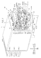
FIG. 1 to FIG. 11 , a configuration of a printer 1 will be described. In the following description, the terms "up," "down," "right," "left," "front" and "rear" are used in the same meaning as indicated by the respective arrows in the drawing. - As shown in
FIG. 1 , the printer 1 is an inkjet printer, and configured to inject a liquid ink 97 (seeFIG. 2 ) onto a fabric (not shown) such as a T-shirt, which is a printing medium, and print a desired image on the fabric. The printing media may be paper or the like. In this embodiment, the printer 1 injects five different kinds of ink 97 (white, black, yellow, cyan, and magenta) downward to print a color image on the printing medium. In the following description, thewhile ink 97 among the five kinds of ink 97 (seeFIG. 2 ) may be referred to as a white ink, and the four colors ofink 97, i.e., black, cyan, yellow and magenta, may collectively be referred to as a color ink. The white ink is high precipitationability liquid that contains a component precipitating faster than the color ink. The component that has high precipitationability is, for example, a pigment such as titanium oxide. - For instance, the white ink is injected onto the fabric, and then the color ink are injected subsequent to the injection of the white ink. The white ink is used as, for example, a foundation when printing an image on the fabric that has a dark ground color. It is also possible to use the white ink in a different printing application than injecting the color ink subsequent to injecting the white ink. Specifically, the fabric surface may include an area injected with the white ink only, and an area injected with the color ink only. For a certain image to be printed, the white ink injection may be subsequent to the color ink injection.
- The printer 1 includes a
housing 2, aplaten drive mechanism 6, a pair of guide rails (not shown), aplaten 5, atray 4, aframe body 10, aguide shaft 9, arail 7, acarriage 20,head units drive belt 101, and adrive motor 19. - The
housing 2 has a substantially rectangular parallelepiped shape that has the longitudinal direction in the right-left direction. On the right front of thehousing 2, there is provided an operation unit (not shown) for operating the printer 1. The operation unit includes a display and operation buttons. The display is configured to display various pieces of information. An operator operates the operation buttons when the operator enters commands and instructions in connection with desired movements, motions and actions of the printer 1. - The
frame body 10 has a frame shape, which has a substantially rectangular shape when viewed from the top, and is located on top of thehousing 2. Theframe body 10 supports theguide shaft 9 at its front side, and supports therail 7 at its rear side. Theguide shaft 9 is a shaft member that has a shaft portion extending in the right-left direction inside theframe body 10. Therail 7 is a rod-shaped member extending in the right-left direction, and located to face theguide shaft 9. - The
carriage 20 can move along theguide shaft 9 in the right-left direction. Thehead units carriage 20. Thehead unit 100 is located behind thehead unit 200. As shown inFIG. 2 andFIG. 3 , each of thehead units head portion 110 at a lower portion thereof.FIG. 2 andFIG. 3 schematically illustrate the vertical locations of respective elements and members of the flow passages of theinks 97. As such,FIG. 2 andFIG. 3 depict thehead units head units head portion 110 of thehead unit 100 injects the white ink. Thehead portion 110 of thehead unit 200 injects the color ink. - The
head portion 110 has anozzle face 111. Thenozzle face 111 is a flat surface that is parallel to the horizontal direction, and includes a plurality of fine nozzles 113 (seeFIG. 2 ) configured to inject theinks 97 downward. Thenozzle face 111 defines a bottom face of each of thehead units nozzles 113 are provided in anozzle arrangement area 120 of thenozzle face 111. Thenozzle arrangement area 120 is formed in a center area of thenozzle face 111 in the right-left direction, and extends in the front-rear direction. - The
nozzle face 111 has a plurality of nozzle arrays 121-124. Each of the nozzle arrays 121-124 is an array of a plurality ofnozzles 113. Each of the nozzle arrays 121-124 is located in corresponding one of four regions defined by dividing thenozzle arrangement area 120 into four parts in the right-left directions. From the right to the left, there are arranged thenozzle array 121, thenozzle array 122, thenozzle array 123 and thenozzle array 124 in this order. - Each of the nozzle arrays 121-124 of the
head unit 100 can inject the white ink. Thenozzle arrays head unit 100 are coupled to asingle cartridge 301 that reserves the white ink (seeFIG. 2 andFIG. 4 ). Thenozzle arrays head unit 100 are coupled to anothercartridge 302 that reserves the white ink (seeFIG. 3 andFIG. 4 ). - As shown in
FIG. 2 andFIG. 3 , each of the nozzle arrays 121-124 of thehead unit 200 is coupled to corresponding one of cartridges 303-306 that retain the color inks. Thenozzle array 121 of thehead unit 200 is coupled to thecartridge 303 of the magenta ink (seeFIG. 2 andFIG. 4 ), thenozzle array 122 is coupled to thecartridge 304 of the cyan ink (seeFIG. 3 andFIG. 4 ), thenozzle array 123 is coupled to thecartridge 305 of the yellow ink (seeFIG. 2 andFIG. 4 ), and thenozzle array 124 is coupled to thecartridge 306 of the black ink (FIG. 3 andFIG. 4 ). - As shown in
FIG. 1 , thedrive belt 101 has a strip shape spanning in the right-left direction inside theframe body 10. Thedrive belt 101 is flexible, and is made from, for example, synthetic resin. Thedrive motor 19 is provided at the right front area inside theframe body 10, and can rotate in the normal and reverse directions. Thedrive motor 19 is operatively connected to thecarriage 20 via thedrive belt 101. As thedrive motor 19 drives thedrive bel 101, thecarriage 20 moves back and forth along theguide shaft 9 in the right-left direction. Accordingly, thehead units inks 97 toward theplaten 5 that is located below thehead units head units - The
platen drive mechanism 6 has a pair of guide rails (not shown) and a platen support (not shown). The two guide rails extend in the front-rear direction inside theplaten drive mechanism 6, and support the platen support such that the platen support can move in the front-rear direction. The platen support is configured to support theplaten 5 at an upper portion thereof. Theplaten 5 supports the printing medium. - The
tray 4 is provided below theplaten 5. Thetray 4 supports sleeves of the T-shirt when the operator puts the T-shirt on theplaten 5. Thus, the sleeves of the T-shirt do not contact components other than the tray in thehousing 2. - The
platen drive mechanism 6 is configured to be driven by a motor (not shown) provided at a rear end of the printer 1. Theplaten drive mechanism 6 is configured to move the platen support and theplaten 5 in the front-rear direction of thehousing 2 along the paired guide rails. As theplaten 5 transports the printing medium in the front-rear direction (sub-scanning direction) and thehead portion 110 injects theinks 97 while moving in the right-left direction in the reciprocal manner, the printer 1 prints on the printing medium. - A
mount frame portion 8 shown inFIG. 4 is provided on the right side of the printer 1. Themount frame portion 8 is supported by the housing 2 (not shown inFIG.4 ). Themount frame portion 8 has a plurality ofmount portions 80, and each of themount portions 80 is configured to mount thecartridge 3. Eachmount portion 80 is a recess that has a rectangular parallelepiped shape, and is concave in the rear direction from the front face of themount frame portion 8. The inner rear end of eachmount portion 80 has a hollow needle (not shown) extending toward the front. As thecartridge 3 is mounted in themount portion 80, the hollow needle sticks in a rubber lid (not shown) provided at a mouth plug 70 (seeFIG. 5 ) of aliquid container 31 received in thecartridge 3. The hollow needle draws out theink 97 from the liquid container 31 (seeFIG. 5 ) held in thecartridge 3. - As shown in
FIG. 5 , thecartridge 3 has acasing 32, theliquid container 31, ashaft 43, and aresilient member 45. Thecasing 32 is a rectangular parallelepiped, which is generally elongated in the front-rear direction. Thecasing 32 has anopening 321 at its rear end. Theliquid container 31 is located in thecasing 32. Theliquid container 31 has aliquid bag 13 and themouth plug 70. Theliquid bag 13 is a bag-like container formed by placing rectangularflexible sheets sheets liquid bag 13 extends in the front-rear direction. The mouth plug 70 is attached to the rear end of theliquid bag 13, and is exposed rearward from theopening 321 of thecasing 32. The mouth plug 70 is a cylindrical element extending in the rear direction, and a rubber plug (not shown) located in themouth plug 70 provides a seal such that theink 97 in theliquid bag 13 does not leak. - The
shaft 43 has a cylindrical shape extending in the right-left direction. Theshaft 43 has projections (not shown) at right and left ends thereof such that the projections project outwardly in the right and left directions respectively. The projections are located inrecesses 53 provided at right and left side faces in thecasing 32. Therecesses 53 are depressed outwardly in the right and left directions, respectively, and extend in the front-rear direction. Theresilient member 45 extend on the bottom face in the front-rear direction inside thecasing 32. A rear end of theresilient member 45 is secured to a rear portion of thecasing 32, and a front end of theresilient member 45 is wound around theshaft 43 such that theresilient member 45 biases theshaft 43 and exerts a returning force in the rear direction. Thus, theshaft 43 winds up theliquid bag 13 and collects theink 97 toward themouth plug 70 as theshaft 43 moves in the rear direction. In other words, theshaft 43 moves in the rear direction as the remaining amount ofink 97 in theliquid container 31 decreases (see thearrow 39 inFIG. 5 ). - The
ink 97 is supplied to thenozzle face 111 from thecartridge 3 engaged in themount portion 80. As shown inFIG. 2 andFIG.3 , a region in the up-down direction is referred to as afirst region 211. Thefirst region 211 is a region in which a distance from thenozzle face 111 in the up-down direction is out of a predetermined range. Also, a region in the up-down direction is referred to as asecond region 212. Thesecond region 212 is a region in which a distance from thenozzle face 111 in the up-down direction is in the predetermined range. In this embodiment, the predetermined range is a range in which a distance measured from thenozzle face 111 in the downward direction falls within a range between the distances L1 and L2. For example, L1 is 10 mm and L2 is 50 mm. As shown in the enlarged view W2 inFIG. 2 , a meniscus is created at thenozzle face 111 by the surface tension, i.e., theink 97 is concave in thenozzle 113. The meniscus holds theink 97 at thenozzle face 111. When theink 97 is supplied toward thenozzle face 111 from thesecond region 212, which is the predetermined range apart from thenozzle face 111 by the predetermined distance in the up-down direction, the meniscus is difficult to break, and it is possible to properly inject theink 97. - As shown in
FIG. 4 andFIG. 6 , themount portions 80 are arranged in two columns side by side in the right-left direction and in three tiers in the up-down direction. As shown inFIG. 2 ,FIG. 3 andFIG. 6 , themount portions 80 includes first mount portions 811-814 located in thefirst region 211, andsecond mount portions second region 212. In this embodiment, thesecond mount portions FIG. 6 , thesecond mount portion 821 is located at the lower right area of themount frame portion 8, and thesecond mount portion 822 is located on the left of thesecond mount portion 821. Thefirst mount portions second mount portions first mount portions first mount portions - The
second mount portions cartridges cartridges - As shown in
FIG. 7 andFIG. 8 , foursub-tanks 91 and four sub-tank supports 92 are provided behind themount frame portion 8. The sub-tanks 91 and the sub-tank supports 92 are located such that they face thesecond mount portions FIG. 2 ,FIG. 3 andFIG. 8 , the sub-tanks 91 are located in thesecond region 212.FIG. 2 andFIG. 3 schematically show the positions of the respective members of the flow passage of theink 97 in the up-down direction. The directions of the sub-tank(s) 91 and the sub-tank support(s) 92 may be different from the directions shown inFIG. 7 . The sub-tanks 91 define reservoir passages 711-714, which will be described later (seeFIG. 2 andFIG. 3 ), and can reserve theink 97 to be supplied to thenozzle face 111 from thecartridge 3. - As shown in
FIG. 2 andFIG. 7 , the sub-tank 91 has abag 93 and mouth plugs 941 and 942. InFIG. 7 , the reference numerals of thebag 93 and the mouth plugs 941 and 942 are only shown for the sub-tank 911 (will be described). Thebag 93 is a bag-shaped container formed by folding a rectangular-shaped flexible sheet made from a material such as synthetic resin and jointing the peripheries of the peripheral portions of the folded sheet by heating and fusing (by means of thermal seal) to provide the bag. It should be noted that thebag 93 may be a bag-like container formed by placing rectangular flexible sheets one after another, which are made from synthetic resin or the like, such that one face of one of the sheets faces one face of the other sheet, and heating and fusing the peripheries of the two sheets (by means of thermal seal) to connect the two sheets to each other. Themouth plug 941 is provided at one end in the longitudinal direction of thebag 93. Themouth plug 942 is provided at the other end in the longitudinal direction of thebag 93. - The
sub-tank support 92 is a member to support the sub-tank 91. As shown inFIG. 7 , thesub-tank support 92 has asupport plate portion 95 and avalve portion 961. InFIG. 7 , the reference numerals of thesupport plate portion 95 and thevalve portion 961 are only shown for thesub-tank support 921, which will be described later. Thesupport plate portion 95 is a plate-like member, and supports the sub-tank 91 on its upper face. Thevalve portion 961 is located at the right end of thesupport plate portion 95, and connects to any of the first connection passages 621-624 (will be described later) and to themouth plug 941 of the sub-tank 91. - The
support plate portion 14 is provided on theback face 81 of themount frame portion 8. Thesupport plate portion 14 supports thesub-tank support 92. As shown inFIG. 7 to Fig. 9 andFIG. 11 , thesupport plate portion 14 has afirst plate portion 141, asecond plate portion 142, and athird plate portion 143. Thefirst plate portion 141 extends rearward from a right end of therear face 81 of themount frame portion 8 in the right-left direction, between thefirst mount portions second mount portions second plate portion 142 connects to the rear end of thefirst plate portion 141 and extends in the right-left direction. Thus, thesecond plate portion 142 is situated behind themount frame portion 8. Thethird plate portion 143 extends in the right-left direction behind thesecond plate portion 142. The lower right end of thethird plate portion 143 is coupled to the lower right end of thesecond plate portion 142 by a plate element (not shown) extending in the front-rear direction. The left end of thesupport plate portion 14 is supported by a frame member (not shown). - The four
sub-tank supports 92 and the four sub-tanks 91 are arranged in two columns side by side in the right-left direction and in two tiers in the front-rear direction. The four sub-tanks 91 are assignedreference numerals sub-tank supports 92 for supporting the four sub-tanks 911-914 are assignedreference numerals - As shown in
FIG. 7 , the sub-tank 913 and thesub-tank support 923 are situated behind the second mount portion 821 (seeFIG. 6 ). The sub-tank 914 and thesub-tank support 924 are situated behind the second mount portion 822 (seeFIG. 6 ). The sub-tank supports 923 and 924 connect to thesecond plate portion 142 of thesupport plate 14. - The sub-tank 911 and the
sub-tank support 921 are situated behind the sub-tank 913 and thesub-tank support 923. The sub-tank 912 and thesub-tank support 922 are situated behind the sub-tank 914 and thesub-tank support 924. Thethird plate portion 143 of thesupport plate 14 is situated behind the sub-tank supports 923 and 924. The sub-tank supports 921 and 922 connect to thethird plate 143, respectively. The sub-tank 91 and thesub-tank support 92 incline to the diagonally upward left direction relative to the horizontal plane. - As shown in
FIG. 7 andFIG. 9 , apump support 15 is attached to theback face 81 of themount frame portion 8. Thepump support 15 supports the pumps 901-904 (seeFIG. 9 ). As shown inFIG. 7 , thepump support 15 has a pair of firstsupport plate portions 151 and a secondsupport plate portion 152. The pair of the firstsupport plate portions 151 respectively extend rearward from the right and left ends of theback face 81 of themount frame portion 8 in the right-left direction, above thefirst mount portions support plate portion 152 connects to the rear lower ends of the pair of the firstsupport plate portions 151, and extends in the right-left direction. The secondsupport plate portion 152 is generally parallel to the horizontal direction. - As shown in
FIG. 9 , the four pumps 901-904 connect to the bottom face of the secondsupport plate portion 152 of thepump support 15, and are arranged in the left direction from the right side. Thus, the four pumps 901-904 are situated behind themount frame portion 8. InFIG. 9 , fluid passages that connect the pumps 901-904 to thehead portion 110 are not shown. - The
ink passage arrangement 700 will be described. As shown inFIG. 2 andFIG. 3 , theink passage arrangement 700 has reservoir passages 711-714 andnon-reservoir passages FIG.2 illustrates the fluid passages which are connected to thefirst mount portions second mount portion 821 on the right column inFIG. 6 .FIG. 3 illustrates the fluid passages which are connected to thefirst mount portions second mount portion 822 on the left column inFIG. 6 . - The reservoir passages 711-714 are fluid passages that connect the first mount portions 811-814 to the
head portion 110 of thehead unit 200, respectively. The reservoir passages 711-714 have sub-tanks 911-914, respectively. The color inks, which are not high precipitationability fluid, flow in the reservoir passages 711-714. Thenon-reservoir passages second mount portions head portion 110 of thehead unit 100, respectively. Thenon-reservoir passages non-reservoir passages - The reservoir passages 711-714 will now be described. The reservoir passages 711-714 include fluid feed ports 611-614, first connection passages 621-624, second connection passages 631-634, and sub-tanks 911-914, respectively. The fluid feed ports 611-614 are provided behind the first mount portions 811-814 at the
rear face 81 of themount frame portion 8, respectively. The fluid feed ports 611-614 connect to the hollow needles (not shown) provided in the first mount portions 811-814 via fluid passages (not shown), respectively. The fluid feed ports 611-614 feed theink 97 to thehead portion 110 from the first mount portions 811-814. - As illustrated in
FIG. 2 ,FIG. 3 ,FIG. 7 andFIG. 10 , one end of each of the first connection passages 621-624 connects to the associatedfluid feed port second region 212, respectively. The other end of each of the first connection passages 621-624 connects to a valve portion 961 (seeFIG. 7 ) of the associatedsub-tank support mouth plug 941 of the associatedsub-tank valve portion 961 has a fluid passage that connects the associatedfirst connection passage corresponding mouth plug 941. Thevalve portion 961 is equipped with a solenoid valve (not shown), and the solenoid valve opens and closes the fluid passage, which extends from the associatedfirst connection passage corresponding mouth plug 941, under the control of a CPU (not shown). Accordingly, the printer 1 can adjust an amount of theink 97 to be introduced into the sub-tank 91. - One end of each of the second connection passages 631-634 connects to the
mouth plug 942 of the associatedsub-tank second connection passage head portion 110 of thehead unit 200, and in turn to the associatednozzle array FIG. 2 andFIG. 3 ). - The
non-reservoir passages FIG. 2 , thenon-reservoir passage 72A has theliquid feed port 73A, acommon passage 74A,branch passages filter portions first branch portion 753A,second branch portions passages Circulation passages non-reservoir passage 72A. As shown inFIG. 2 ,FIG. 8 andFIG. 11 , theliquid feed port 73A is provided behind thesecond mount portion 821 at therear face 81 of themount frame portion 8. Theliquid feed port 73A connects to the hollow needle provided in thesecond mount portion 821 via a fluid passage (not shown). Theliquid feed port 73A feeds theink 97 to thehead portion 110 from thesecond mount portion 821. - The
common passage 74A connects to theliquid feed port 73A, and extends in the rear direction toward the sub-tank 91 from thesecond mount portion 821. Thebranch passages common passage 74A. The branch portion of thecommon passage 74A that branches to thebranch passages first branch portion 753A (seeFIG. 2 andFIG. 11 ). Thefirst branch portion 753A is situated between thesecond mount portion 821 and the sub-tank 913. - As shown in
FIG. 11 , thebranch passage 751A extends to the right from thefirst branch portion 753A. Specifically, thefirst branch portion 753A defines a bend portion that bends in the right direction and that is formed on thenon-reservoir passage 72A. The right direction crosses the rear direction extending from thesecond mount portion 821 to the sub-tank 91. Thebranch passage 752A extends to the left from thefirst branch portion 753A. Specifically, thefirst branch portion 753A defines a bend portion that bends in the left direction and that is formed on thenon-reservoir passage 72A. The left direction crosses the rear direction extending from thesecond mount portion 821 to the sub-tank 91. - As depicted in
FIG. 2 ,FIG. 7 andFIG. 8 , thefeed passage 761A and thecirculation passage 771A connect to the right end of thebranch passage 751A. The branch portion of thebranch passage 751A that branches to thefeed passage 761A and thecirculation passage 771 A is referred to as asecond branch portion 791 A. Thefilter portion 681A is provided at a fluid passage between thesecond mount portion 821 and thesecond branch portion 791 A. In this embodiment, thefilter portion 681A is provided at thebranch passage 751A. Thefilter portion 681A has a disk shape. Thefilter portion 681A possesses a higher passage resistance than a passage resistance of thecirculation passage 771 A. Thefilter portion 681A reduces the possibility of foreign matters, which is contained in theink 97, flowing to the downstream. This is also true to filterportions - The
feed passage 761A extends upward from thesecond branch portion 791A. Specifically, thesecond branch portion 791A defines a bend portion that bends in the up direction crossing the right direction at thenon-reservoir passage 72A. Thefeed passage 761 A extends upward from thesecond branch portion 791 A, and then bends to the left at thebend portion 781A (seeFIG. 7 andFIG. 10 ). As shown inFIG. 2 , thefeed passage 761A connects to thehead portion 110 of thehead unit 100, and in turn to thenozzle 113 arranged in thenozzle array 121. As shown inFIG. 7 , thesecond branch portion 791A and thebend portion 781A are provided on thenon-reservoir passage 72A at positions closer to thehead portion 110 than thefirst branch portion 753A (seeFIG. 11 ), i.e., provided on the downstream side, such that thesecond branch portion 791A and thebend portion 781A are situated between themount portion 80 and the sub-tank 91 in the horizontal direction. - The
circulation passage 771A is a fluid passage through which the white ink, i.e., the high precipitationability liquid from thenon-reservoir passage 72A, circulates. The diameter of thecirculation passage 771 A is smaller than the diameter of thenon-reservoir passage 72A. As shown inFIG. 2 andFIG. 7 , one end of thecirculation passage 771A connects to thefeed passage 761A of thenon-reservoir passage 72A at thesecond branch portion 791A, and the other end of thecirculation passage 771 A connects to thefeed passage 761 A at thehead unit 100. Thesecond branch portion 791A is situated closer to thesecond mount portion 821 than thehead unit 100. As shown inFIG. 2 andFIG. 9 , the pump 904 (seeFIG. 9 ) is provided on thecirculation passage 771A, and the white ink (i.e., high precipitationability liquid) is caused to circulate through thenon-reservoir passage 72A (feedpassage 761A) as thepump 904 is activated. - As shown in
FIG. 2 andFIG. 7 , thecirculation passage 771A extends downward from thesecond branch portion 791A, and then extends below and behind the sub-tank 91 and thesub-tank support 92. Thecirculation passage 771A then extends to thehead unit 100 via the pump 904 (seeFIG. 9 ). As such, part of thecirculation passage 771A is situated below the sub-tank 91. - As shown in
FIG. 2 andFIG. 9 , thefeed passage 762A and thecirculation passage 772A connect to the left end of thebranch passage 752A. A branch portion of thebranch passage 752A, which branches to thefeed passage 762A and thecirculation passage 772A, is referred to as asecond branch portion 792A. Thefilter portion 682A is provided on thebranch passage 752A. Thefilter portion 682A has a disk shape. Thefilter portion 682A has a higher passage resistance than a passage resistance of thecirculation passage 772A. - The
feed passage 762A extends upward from thesecond branch portion 792A. Specifically, thesecond branch portion 792A defines a bend portion that bends in the up direction crossing the left direction at thenon-reservoir passage 72A. Thefeed passage 762A extends upward from thesecond branch portion 792A, and then bends to the left at thebend portion 782A (seeFIG. 10 ). As shown inFIG. 2 , thefeed passage 762A connects to thehead portion 110 of thehead unit 100, and in turn to thenozzle 113 arranged in thenozzle array 122. Thesecond branch portion 792A and thebend portion 782A are provided on thenon-reservoir passage 72A at positions closer to thehead portion 110 than thefirst branch portion 753A, i.e., on the downstream side. Thesecond branch portion 792A and thebend portion 782A are situated between themount portion 80 and the sub-tank 91 in the horizontal direction. - The
circulation passage 772A is a fluid passage through which the white ink, i.e., the high precipitationability liquid from thenon-reservoir passage 72A, circulates. The diameter of thecirculation passage 772A is smaller than the diameter of thenon-reservoir passage 72A. As shown inFIG. 2 andFIG. 9 , one end of thecirculation passage 772A connects to thefeed passage 762A of thenon-reservoir passage 72A at thesecond branch portion 792A, and the other end of thecirculation passage 772A connects to thefeed passage 762A at thehead unit 100. The pump 903 (seeFIG. 9 ) is provided on thecirculation passage 772A, and the white ink, i.e., the high precipitationability liquid, circulates in thenon-reservoir passage 72A (feedpassage 762A) as thepump 903 is activated. - The
circulation passage 772A extends downward from thesecond branch portion 792A, and then extends below and behind the sub-tank 91 and thesub-tank support 92. Thecirculation passage 772A then extends to thehead unit 100 via the pump 903 (seeFIG. 9 ). As such, part of thecirculation passage 772A is situated below the sub-tank 91. Thesecond branch portion 792A is situated closer to thesecond mount portion 821 than thehead unit 100. - As shown in
FIG. 3 , thenon-reservoir passage 72B has aliquid feed port 73B, acommon passage 74B,branch passages filter portions first branch portion 753B,second branch portions passages circulation passages non-reservoir passage 72B. The structures of these components and elements will not be described because the structures of these components and elements are similar to those of theliquid feed port 73A, thecommon passage 74A, thebranch passages first branch portion 753A, thefilter portions second branch portions feed passages circulation passages non-reservoir passage 72A shown inFIG. 2 . As shown inFIG. 10 , thenon-reservoir passage 72B hasbend portions bend portions feed passages bend portions liquid feed port 73B feeds theink 97 to thehead portion 110 from thesecond mount portion 822. Thefeed passages nozzle arrays head unit 100, respectively. Theliquid feed port 73B feeds theink 97 to thehead portion 110 from thesecond mount portion 822. Thepumps circulation passages filter portions circulation passages - The flow of the
ink 97 when a printing operation, which injects theink 97 from thenozzle face 111 for printing, is carried out and a circulating operation, which drives the pumps 901-904 to circulate the white ink (i.e., high precipitationability liquid), is carried out will be described. The printing operation and the circulating operation are carried out as the CPU (not shown) of the printer 1 controls the printer 1 in accordance with a control program stored in a storage unit (not shown). - In the printing operation, as shown in the enlarged view W1 in
FIG. 2 , theink 97 is injected from thenozzle 113 of thenozzle face 111 as a piezo-electric device (not shown) provided at theheat part 110 is activated. The movement of theink 97 injected from thenozzle 113 serves as a pumping force, which pulls theink 97 toward thenozzle face 111. Thus, as shown inFIG. 2 , the white ink is supplied to thenozzle array 121 of thehead unit 100 from thecartridge 301 through theliquid feed port 73A, thecommon passage 74A, thebranch passage 751A and thefeed passage 761A. The white ink is supplied to thenozzle array 122 of thehead unit 100 from thecartridge 301 through theliquid feed port 73A, thecommon passage 74A, thebranch passage 752A and thefeed passage 762A. As shown inFIG. 3 , the white ink is supplied to thenozzle array 123 of thehead unit 100 from thecartridge 302 through theliquid feed port 73B, thecommon passage 74B, thebranch passage 751B and thefeed passage 761B. The white ink is supplied to thenozzle array 124 of thehead unit 100 from thecartridge 302 through theliquid feed port 73B, thecommon passage 74B, thebranch passage 752B and thefeed passage 762B. - A as shown in
FIG. 2 andFIG. 3 , the color ink is supplied to the nozzle arrays 121-124 of thehead unit 200 from the cartridges 303-306 via the first connection passages 621-624, thevalve portion 961, the sub-tanks 911-914 and the second connection passages 631-634, respectively. Because the pumps 901-904 are not activated during the printing, the white ink does not flow in thecirculation passages - As shown in the enlarged view W2 in
FIG. 2 , the meniscus is created on the nozzle face 111 (i.e., theink 97 makes a recess in the nozzle 113) due to the surface tension when the printing is completed. The meniscus holds theink 97 on thenozzle face 111. - The circulating operation will be described. The pumps 901-904 are activated during a no printing time (i.e., while the
ink 97 is not being injected from the nozzle 113) under the control of the CPU to perform the circulating operation. During the circulating operation, as indicated by thearrow 90 inFIG. 2 and thearrow 90 inFIG. 3 , theink 97 is circulated through thefeed passages circulation passages - The printer 1 of this embodiment has the above-described configuration. In this embodiment, the
second mount portions second region 212. Thus, the head difference of theink 97 based on the position of the sub-tanks 91 and the position of thenozzle face 111 becomes substantially equal to the head difference of theink 97 based on the position of thesecond mount portions nozzle face 111. Accordingly, the meniscus properly holds theink 97 on thenozzle face 111, and insufficient injection of theink 97 becomes difficult to occur. As such, it is possible to reduce the possibility of printing quality deterioration. The sub-tanks 91 incline diagonally relative to the horizontal plane, and the upper ends of the sub-tanks 91 are situated slightly above thesecond region 212, but the head of theink 97 in the sub-tanks 91 is in thesecond region 212. In each of thecartridges shaft 43 shown inFIG. 5 is biased in the rear direction by theresilient member 45, and winds up theliquid bag 13. Thus, the pressure for expelling theink 97 from theliquid bag 13 is greater than the pressure when there are noresilient member 45 and theshaft 43. As such, the head of theink 97 within theliquid container 31 in thecartridge second mount portion second region 212. - As shown in
FIG. 2 andFIG. 3 , thenon-reservoir passages head portion 110 from therespective mount portions 80 are only equipped with the sub-tanks 91. Thus, it is possible to reduce the number of parts, as compared to a configuration that has the sub-tanks 91 for all the fluid passages extending to thehead portion 110 from therespective mount portions 80. - The
cartridges second mount portions non-reservoir passages non-reservoir passages nozzle 113 from decreasing. Accordingly, it is possible to reduce the possibility of printing quality deterioration. - Because the
circulation passages non-reservoir passages nozzle 113 would have a reduced concentration, and reduce the possibility of printing quality deterioration. - During the printing, the movement of the
ink 97 injected from thenozzle 113 serves as a pumping force that pulls theink 97 toward thenozzle face 111, and theink 97 is supplied to thenozzle face 111. If the pumps 901-904 are activated during the printing, the pressure exerted by the pumps 901-904 applies to theink 97, and theink 97 may not be injected appropriately. In this embodiment, the pumps 901-904 are activated while the printing is not being carried out, i.e., while theink 97 is not being injected from thenozzle 113. Thus, the white ink, i.e., the high precipitationability liquid, is circulated from thenon-reservoir passages ink 97 is injected appropriately. Because the pumps 901-904 are activated during the no printing time to stir the white ink, the white ink component is difficult to precipitate in thenon-reservoir passages nozzle 113 would have a reduced concentration, and to reduce the possibility that the printing quality would be deteriorated. - The diameter of each of the
circulation passages non-reservoir passages circulation passages circulation passages non-reservoir passages circulation passages pumps circulation passages non-reservoir passages non-reservoir passages nozzle face 111. Thus, it is possible to reduce the possibility of the deterioration in the printing quality. As compared to a configuration that the diameter of each of thecirculation passages non-reservoir passages circulation passages - As shown in
FIG. 11 , thenon-reservoir passages FIG. 2 andFIG. 3 ) bend in a direction that crosses the rear direction heading to the sub-tanks 91 from thesecond mount portions 821 and 822 (seeFIG. 2 ,FIG. 8 andFIG. 3 ) at thefirst branch portions second mount portions first branch portions - As shown in
FIG. 2 ,FIG. 3 andFIG. 7 toFIG. 10 , thesecond branch portions bend portions head portion 110 than thefirst branch portions non-reservoir passages mount portions 80 and the sub-tanks 91 in the horizontal direction. Thus, as compared to a configuration that thefirst branch portions non-reservoir passages non-reservoir passages second branch portions bend portions mount portions 80 when locating thenon-reservoir passages non-reservoir passages non-reservoir passages ink 97 to thenozzle face 111 would become difficult, and the printing quality would drop. - In the
non-reservoir passages second mount portions second branch portions circulation passages second mount portions second branch portions second branch portions second mount portions head unit 100. As a result, it is possible to shorten the lengths of the fluid passages from thesecond mount portions second branch portions second branch portions head unit 100 than thesecond mount portions second branch portions mount portions 80 and the sub-tanks 91 in the horizontal direction. As a result, it is possible to shorten the lengths of the fluid passages from thesecond mount portions second branch portions second branch portions mount portions 80 toward the sub-tanks 91) than the sub-tanks 91. Therefore, it is possible to expand the area for stirring the high precipitationability liquid in thenon-reservoir passages nozzle 113 would have a reduced concentration, and the printing quality would drop. - The
filter portions circulation passages filter portions circulation passages filter portions circulation passages second mount portions filter portions second mount portions ink 97 would not be injected properly from thenozzle 113. This reduces the possibility of printing quality deterioration. - The
second mount portions second region 212. If thesecond mount portions ink 97 to the sub-tanks 91 from the first mount portions 811-814. In this embodiment, thesecond mount portions ink 97 to the sub-tanks 91 from the first mount portions 811-814. Accordingly, it is not necessary to provide pumps to feed theink 97 to the sub-tanks 91, and it is possible to reduce the number of parts. - The
second mount portions circulation passages circulation passages circulation passages sub-tanks 91. Thus, the first connection passages 621-624 extending to the sub-tanks 91 from the first mount portions 811-814 are difficult to interfere with thecirculation passages non-reservoir passages ink 97 to thenozzle face 111 would become difficult. As such, it is possible to reduce the possibility of the printing quality deterioration. - In the above-described embodiment, the printer 1 is an example of the "print device" of the present invention. The
cartridge 3 is an example of the "container" of the present invention. The sub-tank 91 is an example of the "reservoir" of the present invention. Each of thecartridges first branch portions second branch portions bend portions second branch portions - The present invention is not limited to the above-described embodiment, and various changes and modifications may be made to the above-described embodiment. For example, although the high precipitationability liquid is the white in the above-described embodiment, the present invention is not limited in this regard. The high precipitationability liquid may be another liquid as long as the liquid includes a component that has higher precipitationability than the liquid contained in the cartridges 303-304 to be mounted in the first mount portions 811-814. The liquid to be injected from the
nozzle face 111 is not limited to theink 97. For example, the liquid to be injected from thenozzle face 111 may be a discharge printing agent for decoloring a dyed fabric. One of thenon-reservoir passages - Although a certain part of each
circulation passage sub-tank 91, that part of the circulation passage may be located at a position other than below the associated sub-tank. For example, a certain part of thecirculation passage second mount portions second mount portions FIG. 2 ) below thesecond region 212. Thesecond branch portions mount portions 80 and the sub-tanks 91 in the horizontal direction. It should be noted, however, that thesecond branch portions mount portions 80 and the sub-tanks 91 in the horizontal direction. For example, thesecond branch portions head unit 100 than thesecond mount portions - The
second branch portions bend portions non-reservoir passages head portion 110 than thefirst branch portions non-reservoir passage head portion 110 than thefirst branch portions non-reservoir passage non-reservoir passages first branch portions non-reservoir passages first branch portions second mount portions second branch portions bend portions mount portions 80 and the sub-tanks 91 in the horizontal direction, thesecond branch portions bend portions mount portions 80 and the sub-tanks 91. There may be no bend portions at thefirst branch portions first branch portions first branch portions - The pumps 901-904 may be activated during the print time, i.e., while the
ink 97 being injected from thenozzle 113, to circulate the high precipitationability liquid from thenon-reservoir passages feed passages nozzle face 111, and the pumps 901-904 may be activated with the electromagnetic valves being closed, to circulate the high precipitationability liquid. Thecirculation passages feed passages second branch portions second branch portions - The
cartridges second mount portions cartridge 3 for carrying the liquid that contains a component having the same precipitationability as (or a smaller precipitationability than) theink 97, which is carried in the cartridges 303-306 mounted in the first mount portions 811-814, may be located at thesecond mount portions cartridge 3 has theshaft 43 and theresilient member 45 in the above-described embodiment (seeFIG. 5 ), thecartridge 3 may have noshaft 43 and noresilient member 45. Thefilter portions
Claims (11)
- A print device comprising:a head (110) having a nozzle face (111), the nozzle face having a nozzle (113) for injecting liquid; anda plurality of mount portions (80) arranged in an up-down direction, each of the plurality of the mount portions being configured to mount each of a plurality of containers (3), each of the plurality of the containers being configured to contain the liquid;the plurality of the mount portions including:a first mount portion (811-814) located in a first region (211), the first region being a region in which a distance from the nozzle face in the up-down direction being out of a predetermined range; anda second mount portion (821, 822) located in a second region (212), the second region being a region in which a distance from the nozzle face in the up-down direction being in the predetermined range; andthe print device also comprising:a reservoir passage (711-714) configured to connect the first mount portion to the head, and having a reservoir (91) located in the second region, the reservoir being configured to reserve the liquid; anda non-reservoir passage (72A, 72B) configured to connect the second mount portion to the head, and having no reservoir.
- The print device according to claim 1, wherein the second mount portion is configured to mount a high precipitationability liquid container (301, 302) containing high precipitationability liquid, the high precipitationability liquid including a component having higher precipitationability than the liquid contained in the container mounted at the first mount portion.
- The print device according to claim 2, further comprising:a circulation passage (771A, 772A, 771B, 772B) connected to the non-reservoir passage, wherein the high precipitationability liquid from the non-reservoir passage circulates in the circulation passage; anda pump (901-904) provided on the circulation passage and configured to be activated to circulate the high precipitationability liquid in the non-reservoir passage.
- The print device according to claim 3, wherein the high precipitationability liquid from the non-reservoir passage is caused to circulate upon activation of the pump during a no printing time.
- The print device according to any one of claims 1 to 4, wherein the reservoir is located to face the second mount portion in a horizontal direction, wherein the non-reservoir passage has a first bend portion (753A, 753B) that bends in a second direction between the second mount portion and the reservoir located on the reservoir passage, and wherein the second direction crosses a first direction extending to the reservoir from the second mount portion.
- The print device according to claim 5, further comprising at least one second bend portion (791A, 792A, 791B, 792B, 781A, 782A, 781B, 782B) provided on the non-reservoir passage at a position or positions closer to the head than the first bend portion, wherein the at least one second bend portion is located and bends between the mount portion and the reservoir in the horizontal direction.
- The print device according to any one of claims 3 to 6, further comprising a branch portion (791A, 792A, 791B, 792B) on the non-reservoir passage at a position closer to the mount portion than the head, wherein the non-reservoir passage and the circulation passage branch at the branch portion.
- The print device according to claim 7, further comprising a regulator portion (681 A, 682A, 681B, 682B) provided on a fluid passage between the mount portion and the branch portion, wherein passage resistance of the regulator portion is higher than passage resistance of the circulation passage.
- The print device according to any one of claims 3 to 8, wherein the second mount portion is located below the first mount portion.
- The print device according to claim 9, wherein a part of the circulation passage is located below the reservoir.
- The print device according to any one of claims 2 to 10, wherein the high precipitationability liquid is a white ink.
Applications Claiming Priority (1)
| Application Number | Priority Date | Filing Date | Title |
|---|---|---|---|
| JP2014194244A JP6337718B2 (en) | 2014-09-24 | 2014-09-24 | Printing device |
Publications (3)
| Publication Number | Publication Date |
|---|---|
| EP3000604A2 true EP3000604A2 (en) | 2016-03-30 |
| EP3000604A3 EP3000604A3 (en) | 2016-10-26 |
| EP3000604B1 EP3000604B1 (en) | 2019-07-03 |
Family
ID=54150313
Family Applications (1)
| Application Number | Title | Priority Date | Filing Date |
|---|---|---|---|
| EP15185819.8A Active EP3000604B1 (en) | 2014-09-24 | 2015-09-18 | Print device |
Country Status (4)
| Country | Link |
|---|---|
| US (1) | US9333747B2 (en) |
| EP (1) | EP3000604B1 (en) |
| JP (1) | JP6337718B2 (en) |
| CN (1) | CN105437773B (en) |
Families Citing this family (3)
| Publication number | Priority date | Publication date | Assignee | Title |
|---|---|---|---|---|
| JP6384233B2 (en) * | 2014-09-24 | 2018-09-05 | ブラザー工業株式会社 | Printing device |
| KR101967653B1 (en) * | 2016-09-23 | 2019-04-11 | (주)디지아이 | Printing method of the textile printer |
| JP2022125536A (en) * | 2021-02-17 | 2022-08-29 | セイコーエプソン株式会社 | Printing apparatus |
Citations (2)
| Publication number | Priority date | Publication date | Assignee | Title |
|---|---|---|---|---|
| JPH11115203A (en) | 1997-10-20 | 1999-04-27 | Canon Inc | Ink jet recording device |
| JP2012096422A (en) | 2010-11-01 | 2012-05-24 | Seiko Epson Corp | Cartridge assembly, cartridge holder, and printer |
Family Cites Families (20)
| Publication number | Priority date | Publication date | Assignee | Title |
|---|---|---|---|---|
| JPH04358844A (en) * | 1991-06-05 | 1992-12-11 | Canon Inc | inkjet recording device |
| US5745137A (en) * | 1992-08-12 | 1998-04-28 | Hewlett-Packard Company | Continuous refill of spring bag reservoir in an ink-jet swath printer/plotter |
| US6290343B1 (en) * | 1996-07-15 | 2001-09-18 | Hewlett-Packard Company | Monitoring and controlling ink pressurization in a modular ink delivery system for an inkjet printer |
| JPH1199659A (en) * | 1997-09-26 | 1999-04-13 | Brother Ind Ltd | ink cartridge |
| JP2002036583A (en) * | 2000-07-28 | 2002-02-05 | Seiko Epson Corp | Ink jet recording device |
| US6471333B1 (en) * | 2001-04-30 | 2002-10-29 | Hewlett-Packard Company | Method and apparatus for keying ink supply containers |
| JP4089231B2 (en) * | 2002-01-22 | 2008-05-28 | セイコーエプソン株式会社 | Ink filling method and ink jet recording apparatus |
| JP2004174815A (en) * | 2002-11-26 | 2004-06-24 | Canon Inc | Ink head constant negative pressure generator |
| JP2005028612A (en) * | 2003-07-08 | 2005-02-03 | Toshiba Tec Corp | Inkjet recording apparatus and inkjet head |
| JP2005319655A (en) * | 2004-05-07 | 2005-11-17 | Matsushita Electric Ind Co Ltd | Ink supply apparatus in ink jet recording apparatus |
| JP4729948B2 (en) * | 2005-03-09 | 2011-07-20 | ブラザー工業株式会社 | Liquid supply apparatus and ink jet recording apparatus provided with the liquid supply apparatus |
| JP4929917B2 (en) * | 2006-08-17 | 2012-05-09 | セイコーエプソン株式会社 | Assembly structure of cartridge holder and recording apparatus |
| JP2008087193A (en) * | 2006-09-29 | 2008-04-17 | Brother Ind Ltd | Inkjet printer |
| JP4971819B2 (en) * | 2007-02-08 | 2012-07-11 | ローランドディー.ジー.株式会社 | Ink supply system for inkjet printer |
| JP4867689B2 (en) * | 2007-02-13 | 2012-02-01 | ブラザー工業株式会社 | Inkjet recording device |
| JP4971942B2 (en) * | 2007-10-19 | 2012-07-11 | 富士フイルム株式会社 | Inkjet recording apparatus and recording method |
| CN102101387A (en) * | 2009-12-16 | 2011-06-22 | 北大方正集团有限公司 | Gravity ink supply device and method |
| EP2631075A3 (en) * | 2012-02-23 | 2014-03-05 | Dip-Tech Ltd. | A printhead adapter for pigmented ink |
| CN103722890B (en) * | 2012-10-11 | 2015-12-23 | 精工爱普生株式会社 | The providing ink control method of ink-jet printer and ink-jet printer |
| JP6078301B2 (en) * | 2012-11-07 | 2017-02-08 | 株式会社ミマキエンジニアリング | Damper device and inkjet printer |
-
2014
- 2014-09-24 JP JP2014194244A patent/JP6337718B2/en active Active
-
2015
- 2015-09-15 CN CN201510586859.XA patent/CN105437773B/en active Active
- 2015-09-18 EP EP15185819.8A patent/EP3000604B1/en active Active
- 2015-09-18 US US14/858,543 patent/US9333747B2/en active Active
Patent Citations (2)
| Publication number | Priority date | Publication date | Assignee | Title |
|---|---|---|---|---|
| JPH11115203A (en) | 1997-10-20 | 1999-04-27 | Canon Inc | Ink jet recording device |
| JP2012096422A (en) | 2010-11-01 | 2012-05-24 | Seiko Epson Corp | Cartridge assembly, cartridge holder, and printer |
Also Published As
| Publication number | Publication date |
|---|---|
| CN105437773A (en) | 2016-03-30 |
| JP6337718B2 (en) | 2018-06-06 |
| CN105437773B (en) | 2017-06-09 |
| US20160082730A1 (en) | 2016-03-24 |
| EP3000604A3 (en) | 2016-10-26 |
| EP3000604B1 (en) | 2019-07-03 |
| JP2016064558A (en) | 2016-04-28 |
| US9333747B2 (en) | 2016-05-10 |
Similar Documents
| Publication | Publication Date | Title |
|---|---|---|
| US9463632B2 (en) | Print device | |
| US10414164B2 (en) | Cartridge, cartridge unit, and liquid ejection system | |
| KR100466151B1 (en) | Electrical and fluidic interface for an ink supply | |
| EP3000604B1 (en) | Print device | |
| EP2921303B1 (en) | Liquid supply unit | |
| ES2717229T3 (en) | Method for injecting printing material, injection kit and injection device | |
| JP7444214B2 (en) | system | |
| JP2023161025A (en) | tank | |
| JP6972774B2 (en) | Ink consuming device, connection mechanism, ink replenishment container | |
| CN107042691A (en) | Liquid injection apparatus | |
| JP7388002B2 (en) | Liquid container, mounting body, and liquid injection device | |
| WO2007066789A1 (en) | Ink jet printing apparatus and ink tank for the same | |
| US9937724B2 (en) | Liquid ejecting apparatus | |
| US9550368B2 (en) | Print device | |
| US20060091266A1 (en) | Tube interconnect | |
| JP2015178211A (en) | Printer, and check valve unit | |
| CN117799332A (en) | Liquid storage containers and liquid ejection devices | |
| CN205326507U (en) | Liquid supplying system and apparatus incorporating same | |
| KR102819510B1 (en) | Recording apparatus | |
| JP7831123B2 (en) | liquid injection device | |
| JP2023083724A (en) | LIQUID EJECTING DEVICE AND LIQUID EJECTING METHOD | |
| WO2024242093A1 (en) | Liquid storage tank, liquid circulation device, recording device equipped with same, and liquid storage tank group | |
| JP2015116827A (en) | Fluid ejection device | |
| CA2932434A1 (en) | Liquid supply unit | |
| JP2021024178A (en) | Connection auxiliary tool, liquid supply device, and liquid jet device |
Legal Events
| Date | Code | Title | Description |
|---|---|---|---|
| PUAI | Public reference made under article 153(3) epc to a published international application that has entered the european phase |
Free format text: ORIGINAL CODE: 0009012 |
|
| AK | Designated contracting states |
Kind code of ref document: A2 Designated state(s): AL AT BE BG CH CY CZ DE DK EE ES FI FR GB GR HR HU IE IS IT LI LT LU LV MC MK MT NL NO PL PT RO RS SE SI SK SM TR |
|
| AX | Request for extension of the european patent |
Extension state: BA ME |
|
| PUAL | Search report despatched |
Free format text: ORIGINAL CODE: 0009013 |
|
| AK | Designated contracting states |
Kind code of ref document: A3 Designated state(s): AL AT BE BG CH CY CZ DE DK EE ES FI FR GB GR HR HU IE IS IT LI LT LU LV MC MK MT NL NO PL PT RO RS SE SI SK SM TR |
|
| AX | Request for extension of the european patent |
Extension state: BA ME |
|
| RIC1 | Information provided on ipc code assigned before grant |
Ipc: B41J 2/175 20060101AFI20160919BHEP |
|
| STAA | Information on the status of an ep patent application or granted ep patent |
Free format text: STATUS: REQUEST FOR EXAMINATION WAS MADE |
|
| 17P | Request for examination filed |
Effective date: 20170315 |
|
| RBV | Designated contracting states (corrected) |
Designated state(s): AL AT BE BG CH CY CZ DE DK EE ES FI FR GB GR HR HU IE IS IT LI LT LU LV MC MK MT NL NO PL PT RO RS SE SI SK SM TR |
|
| GRAP | Despatch of communication of intention to grant a patent |
Free format text: ORIGINAL CODE: EPIDOSNIGR1 |
|
| STAA | Information on the status of an ep patent application or granted ep patent |
Free format text: STATUS: GRANT OF PATENT IS INTENDED |
|
| INTG | Intention to grant announced |
Effective date: 20190220 |
|
| GRAS | Grant fee paid |
Free format text: ORIGINAL CODE: EPIDOSNIGR3 |
|
| GRAA | (expected) grant |
Free format text: ORIGINAL CODE: 0009210 |
|
| STAA | Information on the status of an ep patent application or granted ep patent |
Free format text: STATUS: THE PATENT HAS BEEN GRANTED |
|
| AK | Designated contracting states |
Kind code of ref document: B1 Designated state(s): AL AT BE BG CH CY CZ DE DK EE ES FI FR GB GR HR HU IE IS IT LI LT LU LV MC MK MT NL NO PL PT RO RS SE SI SK SM TR |
|
| REG | Reference to a national code |
Ref country code: GB Ref legal event code: FG4D |
|
| REG | Reference to a national code |
Ref country code: CH Ref legal event code: EP Ref country code: AT Ref legal event code: REF Ref document number: 1150501 Country of ref document: AT Kind code of ref document: T Effective date: 20190715 |
|
| REG | Reference to a national code |
Ref country code: DE Ref legal event code: R096 Ref document number: 602015033027 Country of ref document: DE |
|
| REG | Reference to a national code |
Ref country code: IE Ref legal event code: FG4D |
|
| REG | Reference to a national code |
Ref country code: NL Ref legal event code: MP Effective date: 20190703 |
|
| REG | Reference to a national code |
Ref country code: LT Ref legal event code: MG4D |
|
| REG | Reference to a national code |
Ref country code: AT Ref legal event code: MK05 Ref document number: 1150501 Country of ref document: AT Kind code of ref document: T Effective date: 20190703 |
|
| PG25 | Lapsed in a contracting state [announced via postgrant information from national office to epo] |
Ref country code: FI Free format text: LAPSE BECAUSE OF FAILURE TO SUBMIT A TRANSLATION OF THE DESCRIPTION OR TO PAY THE FEE WITHIN THE PRESCRIBED TIME-LIMIT Effective date: 20190703 Ref country code: CZ Free format text: LAPSE BECAUSE OF FAILURE TO SUBMIT A TRANSLATION OF THE DESCRIPTION OR TO PAY THE FEE WITHIN THE PRESCRIBED TIME-LIMIT Effective date: 20190703 Ref country code: HR Free format text: LAPSE BECAUSE OF FAILURE TO SUBMIT A TRANSLATION OF THE DESCRIPTION OR TO PAY THE FEE WITHIN THE PRESCRIBED TIME-LIMIT Effective date: 20190703 Ref country code: BG Free format text: LAPSE BECAUSE OF FAILURE TO SUBMIT A TRANSLATION OF THE DESCRIPTION OR TO PAY THE FEE WITHIN THE PRESCRIBED TIME-LIMIT Effective date: 20191003 Ref country code: NL Free format text: LAPSE BECAUSE OF FAILURE TO SUBMIT A TRANSLATION OF THE DESCRIPTION OR TO PAY THE FEE WITHIN THE PRESCRIBED TIME-LIMIT Effective date: 20190703 Ref country code: NO Free format text: LAPSE BECAUSE OF FAILURE TO SUBMIT A TRANSLATION OF THE DESCRIPTION OR TO PAY THE FEE WITHIN THE PRESCRIBED TIME-LIMIT Effective date: 20191003 Ref country code: SE Free format text: LAPSE BECAUSE OF FAILURE TO SUBMIT A TRANSLATION OF THE DESCRIPTION OR TO PAY THE FEE WITHIN THE PRESCRIBED TIME-LIMIT Effective date: 20190703 Ref country code: PT Free format text: LAPSE BECAUSE OF FAILURE TO SUBMIT A TRANSLATION OF THE DESCRIPTION OR TO PAY THE FEE WITHIN THE PRESCRIBED TIME-LIMIT Effective date: 20191104 Ref country code: LT Free format text: LAPSE BECAUSE OF FAILURE TO SUBMIT A TRANSLATION OF THE DESCRIPTION OR TO PAY THE FEE WITHIN THE PRESCRIBED TIME-LIMIT Effective date: 20190703 Ref country code: AT Free format text: LAPSE BECAUSE OF FAILURE TO SUBMIT A TRANSLATION OF THE DESCRIPTION OR TO PAY THE FEE WITHIN THE PRESCRIBED TIME-LIMIT Effective date: 20190703 |
|
| PG25 | Lapsed in a contracting state [announced via postgrant information from national office to epo] |
Ref country code: ES Free format text: LAPSE BECAUSE OF FAILURE TO SUBMIT A TRANSLATION OF THE DESCRIPTION OR TO PAY THE FEE WITHIN THE PRESCRIBED TIME-LIMIT Effective date: 20190703 Ref country code: AL Free format text: LAPSE BECAUSE OF FAILURE TO SUBMIT A TRANSLATION OF THE DESCRIPTION OR TO PAY THE FEE WITHIN THE PRESCRIBED TIME-LIMIT Effective date: 20190703 Ref country code: LV Free format text: LAPSE BECAUSE OF FAILURE TO SUBMIT A TRANSLATION OF THE DESCRIPTION OR TO PAY THE FEE WITHIN THE PRESCRIBED TIME-LIMIT Effective date: 20190703 Ref country code: IS Free format text: LAPSE BECAUSE OF FAILURE TO SUBMIT A TRANSLATION OF THE DESCRIPTION OR TO PAY THE FEE WITHIN THE PRESCRIBED TIME-LIMIT Effective date: 20191103 Ref country code: GR Free format text: LAPSE BECAUSE OF FAILURE TO SUBMIT A TRANSLATION OF THE DESCRIPTION OR TO PAY THE FEE WITHIN THE PRESCRIBED TIME-LIMIT Effective date: 20191004 Ref country code: RS Free format text: LAPSE BECAUSE OF FAILURE TO SUBMIT A TRANSLATION OF THE DESCRIPTION OR TO PAY THE FEE WITHIN THE PRESCRIBED TIME-LIMIT Effective date: 20190703 |
|
| PG25 | Lapsed in a contracting state [announced via postgrant information from national office to epo] |
Ref country code: TR Free format text: LAPSE BECAUSE OF FAILURE TO SUBMIT A TRANSLATION OF THE DESCRIPTION OR TO PAY THE FEE WITHIN THE PRESCRIBED TIME-LIMIT Effective date: 20190703 |
|
| PG25 | Lapsed in a contracting state [announced via postgrant information from national office to epo] |
Ref country code: EE Free format text: LAPSE BECAUSE OF FAILURE TO SUBMIT A TRANSLATION OF THE DESCRIPTION OR TO PAY THE FEE WITHIN THE PRESCRIBED TIME-LIMIT Effective date: 20190703 Ref country code: PL Free format text: LAPSE BECAUSE OF FAILURE TO SUBMIT A TRANSLATION OF THE DESCRIPTION OR TO PAY THE FEE WITHIN THE PRESCRIBED TIME-LIMIT Effective date: 20190703 Ref country code: RO Free format text: LAPSE BECAUSE OF FAILURE TO SUBMIT A TRANSLATION OF THE DESCRIPTION OR TO PAY THE FEE WITHIN THE PRESCRIBED TIME-LIMIT Effective date: 20190703 Ref country code: DK Free format text: LAPSE BECAUSE OF FAILURE TO SUBMIT A TRANSLATION OF THE DESCRIPTION OR TO PAY THE FEE WITHIN THE PRESCRIBED TIME-LIMIT Effective date: 20190703 |
|
| PG25 | Lapsed in a contracting state [announced via postgrant information from national office to epo] |
Ref country code: SK Free format text: LAPSE BECAUSE OF FAILURE TO SUBMIT A TRANSLATION OF THE DESCRIPTION OR TO PAY THE FEE WITHIN THE PRESCRIBED TIME-LIMIT Effective date: 20190703 Ref country code: IS Free format text: LAPSE BECAUSE OF FAILURE TO SUBMIT A TRANSLATION OF THE DESCRIPTION OR TO PAY THE FEE WITHIN THE PRESCRIBED TIME-LIMIT Effective date: 20200224 Ref country code: SM Free format text: LAPSE BECAUSE OF FAILURE TO SUBMIT A TRANSLATION OF THE DESCRIPTION OR TO PAY THE FEE WITHIN THE PRESCRIBED TIME-LIMIT Effective date: 20190703 Ref country code: MC Free format text: LAPSE BECAUSE OF FAILURE TO SUBMIT A TRANSLATION OF THE DESCRIPTION OR TO PAY THE FEE WITHIN THE PRESCRIBED TIME-LIMIT Effective date: 20190703 |
|
| REG | Reference to a national code |
Ref country code: CH Ref legal event code: PL |
|
| REG | Reference to a national code |
Ref country code: DE Ref legal event code: R097 Ref document number: 602015033027 Country of ref document: DE |
|
| PLBE | No opposition filed within time limit |
Free format text: ORIGINAL CODE: 0009261 |
|
| STAA | Information on the status of an ep patent application or granted ep patent |
Free format text: STATUS: NO OPPOSITION FILED WITHIN TIME LIMIT |
|
| PG2D | Information on lapse in contracting state deleted |
Ref country code: IS |
|
| PG25 | Lapsed in a contracting state [announced via postgrant information from national office to epo] |
Ref country code: CH Free format text: LAPSE BECAUSE OF NON-PAYMENT OF DUE FEES Effective date: 20190930 Ref country code: IE Free format text: LAPSE BECAUSE OF NON-PAYMENT OF DUE FEES Effective date: 20190918 Ref country code: LU Free format text: LAPSE BECAUSE OF NON-PAYMENT OF DUE FEES Effective date: 20190918 Ref country code: LI Free format text: LAPSE BECAUSE OF NON-PAYMENT OF DUE FEES Effective date: 20190930 |
|
| REG | Reference to a national code |
Ref country code: BE Ref legal event code: MM Effective date: 20190930 |
|
| 26N | No opposition filed |
Effective date: 20200603 |
|
| PG25 | Lapsed in a contracting state [announced via postgrant information from national office to epo] |
Ref country code: SI Free format text: LAPSE BECAUSE OF FAILURE TO SUBMIT A TRANSLATION OF THE DESCRIPTION OR TO PAY THE FEE WITHIN THE PRESCRIBED TIME-LIMIT Effective date: 20190703 Ref country code: BE Free format text: LAPSE BECAUSE OF NON-PAYMENT OF DUE FEES Effective date: 20190930 |
|
| PG25 | Lapsed in a contracting state [announced via postgrant information from national office to epo] |
Ref country code: CY Free format text: LAPSE BECAUSE OF FAILURE TO SUBMIT A TRANSLATION OF THE DESCRIPTION OR TO PAY THE FEE WITHIN THE PRESCRIBED TIME-LIMIT Effective date: 20190703 |
|
| PG25 | Lapsed in a contracting state [announced via postgrant information from national office to epo] |
Ref country code: HU Free format text: LAPSE BECAUSE OF FAILURE TO SUBMIT A TRANSLATION OF THE DESCRIPTION OR TO PAY THE FEE WITHIN THE PRESCRIBED TIME-LIMIT; INVALID AB INITIO Effective date: 20150918 Ref country code: MT Free format text: LAPSE BECAUSE OF FAILURE TO SUBMIT A TRANSLATION OF THE DESCRIPTION OR TO PAY THE FEE WITHIN THE PRESCRIBED TIME-LIMIT Effective date: 20190703 |
|
| PG25 | Lapsed in a contracting state [announced via postgrant information from national office to epo] |
Ref country code: MK Free format text: LAPSE BECAUSE OF FAILURE TO SUBMIT A TRANSLATION OF THE DESCRIPTION OR TO PAY THE FEE WITHIN THE PRESCRIBED TIME-LIMIT Effective date: 20190703 |
|
| P01 | Opt-out of the competence of the unified patent court (upc) registered |
Effective date: 20230529 |
|
| PGFP | Annual fee paid to national office [announced via postgrant information from national office to epo] |
Ref country code: DE Payment date: 20250808 Year of fee payment: 11 |
|
| PGFP | Annual fee paid to national office [announced via postgrant information from national office to epo] |
Ref country code: IT Payment date: 20250911 Year of fee payment: 11 |
|
| PGFP | Annual fee paid to national office [announced via postgrant information from national office to epo] |
Ref country code: GB Payment date: 20250814 Year of fee payment: 11 |
|
| PGFP | Annual fee paid to national office [announced via postgrant information from national office to epo] |
Ref country code: FR Payment date: 20250808 Year of fee payment: 11 |