EP3000458A1 - Pill inspection device and pill inspection method - Google Patents
Pill inspection device and pill inspection method Download PDFInfo
- Publication number
- EP3000458A1 EP3000458A1 EP14801582.9A EP14801582A EP3000458A1 EP 3000458 A1 EP3000458 A1 EP 3000458A1 EP 14801582 A EP14801582 A EP 14801582A EP 3000458 A1 EP3000458 A1 EP 3000458A1
- Authority
- EP
- European Patent Office
- Prior art keywords
- pill
- light
- translucent
- pills
- inspection apparatus
- Prior art date
- Legal status (The legal status is an assumption and is not a legal conclusion. Google has not performed a legal analysis and makes no representation as to the accuracy of the status listed.)
- Granted
Links
Images






Classifications
-
- G—PHYSICS
- G01—MEASURING; TESTING
- G01N—INVESTIGATING OR ANALYSING MATERIALS BY DETERMINING THEIR CHEMICAL OR PHYSICAL PROPERTIES
- G01N21/00—Investigating or analysing materials by the use of optical means, i.e. using sub-millimetre waves, infrared, visible or ultraviolet light
- G01N21/84—Systems specially adapted for particular applications
- G01N21/88—Investigating the presence of flaws or contamination
- G01N21/95—Investigating the presence of flaws or contamination characterised by the material or shape of the object to be examined
- G01N21/9508—Capsules; Tablets
-
- A—HUMAN NECESSITIES
- A61—MEDICAL OR VETERINARY SCIENCE; HYGIENE
- A61J—CONTAINERS SPECIALLY ADAPTED FOR MEDICAL OR PHARMACEUTICAL PURPOSES; DEVICES OR METHODS SPECIALLY ADAPTED FOR BRINGING PHARMACEUTICAL PRODUCTS INTO PARTICULAR PHYSICAL OR ADMINISTERING FORMS; DEVICES FOR ADMINISTERING FOOD OR MEDICINES ORALLY; BABY COMFORTERS; DEVICES FOR RECEIVING SPITTLE
- A61J1/00—Containers specially adapted for medical or pharmaceutical purposes
- A61J1/03—Containers specially adapted for medical or pharmaceutical purposes for pills or tablets
-
- G—PHYSICS
- G01—MEASURING; TESTING
- G01N—INVESTIGATING OR ANALYSING MATERIALS BY DETERMINING THEIR CHEMICAL OR PHYSICAL PROPERTIES
- G01N21/00—Investigating or analysing materials by the use of optical means, i.e. using sub-millimetre waves, infrared, visible or ultraviolet light
- G01N21/84—Systems specially adapted for particular applications
- G01N21/88—Investigating the presence of flaws or contamination
- G01N21/8851—Scan or image signal processing specially adapted therefor, e.g. for scan signal adjustment, for detecting different kinds of defects, for compensating for structures, markings, edges
-
- A—HUMAN NECESSITIES
- A61—MEDICAL OR VETERINARY SCIENCE; HYGIENE
- A61J—CONTAINERS SPECIALLY ADAPTED FOR MEDICAL OR PHARMACEUTICAL PURPOSES; DEVICES OR METHODS SPECIALLY ADAPTED FOR BRINGING PHARMACEUTICAL PRODUCTS INTO PARTICULAR PHYSICAL OR ADMINISTERING FORMS; DEVICES FOR ADMINISTERING FOOD OR MEDICINES ORALLY; BABY COMFORTERS; DEVICES FOR RECEIVING SPITTLE
- A61J1/00—Containers specially adapted for medical or pharmaceutical purposes
- A61J1/03—Containers specially adapted for medical or pharmaceutical purposes for pills or tablets
- A61J1/035—Blister-type containers
-
- A—HUMAN NECESSITIES
- A61—MEDICAL OR VETERINARY SCIENCE; HYGIENE
- A61J—CONTAINERS SPECIALLY ADAPTED FOR MEDICAL OR PHARMACEUTICAL PURPOSES; DEVICES OR METHODS SPECIALLY ADAPTED FOR BRINGING PHARMACEUTICAL PRODUCTS INTO PARTICULAR PHYSICAL OR ADMINISTERING FORMS; DEVICES FOR ADMINISTERING FOOD OR MEDICINES ORALLY; BABY COMFORTERS; DEVICES FOR RECEIVING SPITTLE
- A61J2205/00—General identification or selection means
- A61J2205/40—General identification or selection means by shape or form, e.g. by using shape recognition
-
- G—PHYSICS
- G01—MEASURING; TESTING
- G01N—INVESTIGATING OR ANALYSING MATERIALS BY DETERMINING THEIR CHEMICAL OR PHYSICAL PROPERTIES
- G01N21/00—Investigating or analysing materials by the use of optical means, i.e. using sub-millimetre waves, infrared, visible or ultraviolet light
- G01N21/84—Systems specially adapted for particular applications
- G01N2021/845—Objects on a conveyor
-
- G—PHYSICS
- G01—MEASURING; TESTING
- G01N—INVESTIGATING OR ANALYSING MATERIALS BY DETERMINING THEIR CHEMICAL OR PHYSICAL PROPERTIES
- G01N21/00—Investigating or analysing materials by the use of optical means, i.e. using sub-millimetre waves, infrared, visible or ultraviolet light
- G01N21/84—Systems specially adapted for particular applications
- G01N21/88—Investigating the presence of flaws or contamination
- G01N21/8806—Specially adapted optical and illumination features
- G01N2021/8841—Illumination and detection on two sides of object
Definitions
- the present invention relates to a pill inspection apparatus and a pill inspection method for inspecting a pill enclosed in a medical envelope.
- a pill packaging machine first carries out a packaging operation for packaging different kinds of pills in a medical envelope which is a medical bag.
- a pill inspection apparatus takes an image of the medical envelope and binarizes the shot images (taken pictures) and then, counts the number of pills existing in the binarized image, and inspects the pills.
- Permeation rates of the translucent pills vary depending upon their kinds, and brightness values of the translucent pills on their images are also different from each other. Depending upon kinds of the translucent pills, brightness value distribution of translucent pills partially overlap brightness value distribution of a back ground. Therefore, it is difficult to precisely carry out the inspection.
- Figs. 6 show a conceptual diagram and a shot image of transmission of a translucent pill when diffusion light is used as illumination.
- light which can be received by an imaging portion 11 is limited to light which moves along lines 35a, 35b, 35c, 35d, 35e, 35f and 35g.
- Light which passes through centers of translucent pills 22 straightly travels along the line 35d, and as the light comes close to an outer peripheral portion in the order of the lines 35c, 35b and 35a, refraction at the translucent pills 22 becomes large.
- light irradiated from a light emitting portion 31 is diffusion light in this manner, since irradiation angles of light are various, light irradiated from the light emitting portion 31 reaches the imaging portion 11 at any angles of the lines 35a, 35b, 35c, 35d, 35e, 35f and 35g.
- pixels having low brightness values showing the translucent pills 22 are not produced, outlines of the translucent pills 22 are clearly shot on the transmission image which is acquired by the imaging portion 11.
- the back ground means a region where pills do not exist in the shot image, and is a region which passes through only the transparency film.
- Figs. 7 show a conceptual diagram and a shot image of transmission of a translucent pill when parallel light is used as illumination.
- an illumination portion 30 to emit parallel light, includes a parallel light converting portion 32 for converting diffusion light into parallel light and also includes a light emitting portion 31.
- a brightness value of a center of the translucent pill 22 becomes high and a brightness value of the outer periphery becomes low. Therefore, an outline of the translucent pill 22 is clearly shot on the transmission image which is acquired by the imaging portion 11.
- Fig. 8 is a diagram for explaining parallel light which is irradiated from an illumination portion.
- a brightness value of the outer periphery of the translucent pill 22 becomes low irrespective of a permeation rate of the translucent pill 22.
- the outline can be clarified, but when the translucent pill 22 exists at a position deviated from directly below the imaging portion 11, deviation is generated in the outline.
- Fig. 9(a) is an explanatory diagram when the translucent pill 22 exists at the position deviated from directly below the imaging portion 11, and Fig. 9(b) is a shot image.
- a first aspect of the present invention provides a pill inspection apparatus including: an illumination portion for irradiating light to a medical envelope in which at least a translucent pill is enclosed; an imaging portion for acquiring a transmission image of the irradiated medical envelope; and an image processing portion for detecting, as the translucent pill, a pill having a brightness value of its outer periphery lower than that of its center using the transmission image, wherein the illumination portion includes a light emitting portion, and a light-collecting portion for collecting the light is provided between the light emitting portion and the medical envelope.
- the light emitting portion emits diffusion light
- a parallel light converting portion for converting the diffusion light into parallel light is provided between the light emitting portion and the light-collecting portion.
- the light-collecting portion is a convex lens or a Fresnel lens.
- a domical illumination portion is provided between the medical envelope and the imaging portion.
- a fifth aspect of the present invention provides a pill inspection method including: a step of irradiating light to a medical envelope in which at least a translucent pill is enclosed to acquire a transmission image; a step of detecting, as the translucent pill, a pill having a brightness value of its outer periphery lower than that of its center using the transmission image; and a step of collecting the light from an illumination portion into an imaging portion.
- a pill inspection apparatus and a pill inspection method capable of inspecting a translucent pill irrespective of a permeation rate by obtaining a uniform outline of the translucent pill irrespective of a shooting position.
- a pill inspection apparatus includes a light-collecting portion for collecting the light is provided between the light emitting portion and the medical envelope. According to this aspect, it is possible to inspect a translucent pill irrespective of a permeation rate by obtaining a uniform outline of the translucent pill irrespective of a shooting position.
- the light emitting portion emits diffusion light
- a parallel light converting portion for converting the diffusion light into parallel light is provided between the light emitting portion and the light-collecting portion. According to this aspect, by collecting the parallel light after the diffusion light is converted into the parallel light, it is possible to obtain a uniform outline of the translucent pill.
- the light-collecting portion is a convex lens or a Fresnel lens. According to this aspect, by using the Fresnel lens, it is possible to shorten a distance between an illumination portion and the medical envelope.
- a domical illumination portion is provided between the medical envelope and the imaging portion. According to this aspect, even if the domical illumination is provided, it is possible to obtain a uniform outline of the translucent pill without being influenced by the domical illumination.
- a pill inspection method includes a step of irradiating light to a medical envelope in which at least a translucent pill is enclosed to acquire a transmission image; a step of detecting, as the translucent pill, a pill having a brightness value of its outer periphery lower than that of its center using the transmission image; and a step of collecting the light from an illumination portion into an imaging portion. According to this aspect, it is possible to inspect a translucent pill irrespective of a permeation rate by obtaining a uniform outline of the translucent pill irrespective of a shooting position.
- Fig. 1 is a block diagram showing a pill inspection apparatus according to the embodiment of the invention
- Fig. 2 is a perspective view of a parallel light converting portion used in the pill inspection apparatus.
- the same reference symbols are allocated to the same constituent elements, and explanation thereof will be omitted in some cases. For ease of comprehension, the drawings are illustrated schematically mainly based on the respective constituent elements.
- the pill inspection apparatus inspects whether appropriate pills are enclosed in a medical envelope 20 in accordance with prescription. Pills according to the prescription are enclosed in the medical envelope 20 by a pill packaging machine (not shown).
- the pill inspection apparatus acquires an image of the medical envelope 20 including an opaque pill and a translucent pill by an imaging portion 11.
- An image processing portion 12 counts the number of pills based on the image of the medical envelope 20 acquired by the imaging portion 11, brings the counted number and the number of pills described in the prescription into check, and determines whether the pills are appropriately enclosed in the medical envelope 20.
- a camera portion is used as the imaging portion 11 for example.
- the imaging portion 11 acquires a transmission image of the medical envelope 20 into which light is irradiated from an illumination portion 30.
- the imaging portion 11 includes an image element and a lens.
- a mounting table 13 conveys the medical envelope 20.
- the mounting table 13 includes a guide portion 15 provided on an end of a mounting surface.
- the medical envelope 20 is mounted on the mounting surface.
- the mounting table 13 also includes a transparent plate 16 through which light of the illumination portion 30 passes.
- the guide portion 15 is provided therein with a drive roller and a guide roller (both not shown). An end of the medical envelope 20 is sandwiched between the drive roller and the guide roller, and the drive roller is rotated. According to this, the medical envelope 20 is moved along the guide portion 15.
- the mounting table 13 is placed between the imaging portion 11 and the illumination portion 30.
- the imaging portion 11 is opposed to the mounting surface of the mounting table 13 on which the medical envelope 20 is mounted, and the imaging portion 11 is located above the illumination portion 30.
- the imaging portion 11 shots, from above, an image of the medical envelope 20 into which light is irradiated from below the mounting surface, and acquires a transmission image of the medical envelope 20.
- a display portion 14 is connected to the image processing portion 12, and displays an image of pills detected by the image processing portion 12. Hence, a tester (examiner) can visually inspects using the display portion 14.
- a domical illumination portion 40 is provided below the imaging portion 11 and above the transparent plate 16.
- the medical envelope 20 is irradiated with light from the domical illumination portion 40, and the medical envelope 20 is shot by the camera unit 11.
- the illumination portion 30 irradiates, with light, the medical envelope 20 enclosing the translucent pills 22 and the opaque pills 21.
- the illumination portion 30 includes a light emitting portion 31 which emits diffusion light, a parallel light converting portion 32 which converts diffusion light into parallel light, and a light-collecting portion 33 which collects parallel light.
- a LED which is mounted to a diffusion plate is used as the light emitting portion 31.
- a convex lens or a Fresnel lens is used as the light-collecting portion 33.
- a distance from the imaging portion 11 to the light-collecting portion 33 is equal to a focal distance of the light-collecting portion 33.
- light is collected by the light-collecting portion 33 after diffusion light is converted into the parallel light by the parallel light converting portion 32.
- light diffused from a single light source may be collected. In this case, the distance from the imaging portion 11 to the light-collecting portion 33 is equal to a half of the focal distance of the light-collecting portion 33.
- the opaque pills 21 which block light and translucent pills 22 through which light passes with a constant transmission factor are enclosed in the medical envelope 20.
- the opaque pill 21 blocks light. Many of general pills are opaque pills 21.
- Each of the translucent pills 22 encloses medicinal solution with a transparent film. Hence a degree of transmission of light differs depending upon a degree of transmission of the medicinal solution. Since the translucent pill 22 encloses the medicinal solution, the translucent pill 22 has a roundish shape such as a ball shape, a spheroid shape and a capsule shape.
- the medical envelope 20 includes a pasted board region 20a having a permeation rate lower than that of the transparency film so that information is printed.
- the medical envelope 20 also includes non-pasted board regions 20b of transparency films.
- the imaging portion 11 acquires a transmission image of the medical envelope 20.
- the transmission image includes translucent pills 22 having low brightness values of an obtained outer periphery. Utilizing the fact that the brightness value of the outer periphery of the translucent pill 22 becomes low, the image processing portion 12 detects an outline of the translucent pill 22 from the transmission image of the medical envelope 20.
- the pill inspection apparatus After the pill inspection apparatus acquires the transmission image of the medical envelope 20 by the imaging portion 11, the pill inspection apparatus detects translucent pills 22 included in the transmission image of the medical envelope 20 and detects opaque pills 21 included in the transmission image of the medical envelope 20. The number of pills of the prescription and a sum of the number of detected translucent pills 22 and the number of detected opaque pills 21 are compared with each other, and it is determined whether an appropriate number of pills exist in the medical envelope 20, thereby checking the number of pills. The pill inspection apparatus inspects the pills in such a method. Details of the checking operation of the number of pills carried out by the pill inspection apparatus will be described based on a flowchart shown in Fig. 5 .
- the parallel light converting portion 32 converts diffusion light into parallel light.
- the parallel light converting portion 32 is formed of laminated bodies 32c and 32d which are formed by laminating, on one another, transmission bands 32a through which visible light passes and absorption belts 32b which absorb visible light.
- the laminated body 32c and the laminated body 32d are superposed on each other such that a laminating direction of the transmission band 32a and the absorption belt 32b of the laminated body 32c and a laminating direction of the transmission band 32a and the absorption belt 32b of the laminated body 32d intersect with each other at right angles.
- Fig. 3(a) is a conceptual diagram of transmission of the translucent pills 22 when light is collected at the imaging portion 11, and Fig. 3(b) is a diagram showing transmission image of the shot translucent pills 22.
- Fig. 3(a) shows a translucent pill 22A located directly below the imaging portion 11 in the vertical direction, and a translucent pill 22B located at a position deviated from directly below the imaging portion 11 in the vertical direction.
- Each of the translucent pills 22 has a roundish shape.
- the translucent pill 22 plays a role as a lens, light passing through the outer periphery of the translucent pill 22 is refracted, and light passing through a center thereof straightly travels.
- the translucent pill 22 located directly below the imaging portion 11 in the vertical direction, light passing through the center reaches the imaging portion 11 and its brightness value becomes high like the parallel light, but light passing through the outer periphery which enters the imaging portion 11 becomes weak, and its brightness value becomes low.
- the translucent pill 22 has a roundish shape such as a ball shape, a spheroid shape and a capsule shape, and a refraction index thereof is gradually varied from the outer periphery toward the center of the translucent pill 22. Therefore, the outer periphery where the brightness value becomes low has a width of a certain level. A shape of a region having the low brightness value matches with an outline shape of the translucent pill 22. Therefore, image processing for comparing the shapes, e.g., image processing such as pattern matching becomes easy.
- Figs. 4 are conceptual diagrams of transmission of translucent pills when the domical illumination shown in Fig. 1 is provided
- Fig. 4(a) shows the present embodiment where light is collected by the imaging portion
- Fig. 4(b) shows a transmission image of the translucent pills
- Fig. 4(c) shows a comparative example using diffusion light
- Fig. 4(d) shows a comparative example using parallel light.
- thickness of arrows shows intensity of light.
- the feature of illumination using parallel light i.e., the feature that the brightness value of the center of the translucent pill 22 is high and the brightness value of the outer periphery is low becomes weak due to the fact that the brightness value of the entire translucent pill 22 becomes high, and it becomes difficult to detect the translucent pill 22.
- an outline of the opaque pill 21 located at a position away from directly below the imaging portion 11 in the vertical direction is also clear, and the outline of the outer periphery of the translucent pill 22 is also uniform and clear.
- the image processing portion 12 can easily detect the outlines of the opaque pill 21 and the translucent pill 22 by the transmission image.
- detection of the translucent pill 22 is carried out by pattern matching between the transmission image and sample images of the translucent pills 22, and the number of detected translucent pills 22 is calculated. Further, since images of the opaque pill 21 and the translucent pill 22 are different from each other due to a difference in the transmission factor, it is possible to clearly distinguish between the opaque pill 21 and the translucent pill 22 in this embodiment.
- the image processing portion 12 Before the pattern matching between the transmission image and the sample image of the translucent pill 22 is carried out, the image processing portion 12 carries out a thinning operation and edge extraction by an extreme value with respect to the transmission image, and detects an outline of the translucent pill 22 by the transmission image. By carrying out the thinning operation and edge extraction by the extreme value with respect to the transmission image in this manner, noise is removed, and the outline of the pill is clarified.
- the brightness value of the outer periphery of the translucent pill 22 is low and its width is constant as described above. However, if parallel light in which light is not collected is used, a refraction index of light which reaches the imaging portion 11 is changed depending upon an attitude of the pill and a relative position from the imaging portion 11.
- the medical envelope 20 includes a pasted board region 20a having a permeation rate lower than that of the transparency film for printing, and a non-pasted board region 20b of the transparency film.
- the pasted board region 20a if the translucent pill 22 exists on a boundary between the pasted board region 20a and the non-pasted board region 20b for weakening light of the illumination portion 30, a brightness value of one translucent pill 22 differs on the side of the pasted board region 20a and on the side of the non-pasted board region 20b.
- the outline is erroneously detected in some cases.
- the transmission image of the medical envelope 20 is divided into the pasted board region 20a and the non-pasted board region 20b, and the outline of the translucent pill 22 is detected using two threshold values, i.e., a pasted board region threshold value for detecting the outline of the translucent pill 22 by the pasted board region 20a, and a non-pasted board region threshold value for detecting the outline of the translucent pill 22 by the non-pasted board region 20b.
- a pasted board region threshold value for detecting the outline of the translucent pill 22 by the pasted board region 20a
- a non-pasted board region threshold value for detecting the outline of the translucent pill 22 by the non-pasted board region 20b.
- the image processing portion 12 uses the two threshold values for detecting the outline of the translucent pill 22 in this manner, even if the translucent pills 22 exist in the pasted board region 20a and the non-pasted board region 20b, the translucent pills 22 can be detected as one pill.
- the image processing portion 12 When the image processing portion 12 extracts the edge, the image processing portion 12 recognizes the longest line and the second longest as a boundary line of the pasted board region 20a, and recognizes a space between these two lines as the pasted board region 20a. Since the pasted board region 20a is formed as a wide range so that it is easy to notice, it is possible to easily discriminate the pasted board region 20a by detecting the longest line and the second longest line.
- Fig. 5 is a flowchart showing the pill inspection method using the pill inspection apparatus of the present embodiment.
- the pill inspection apparatus collects parallel light from the parallel light converting portion 32 at the imaging portion 11 by the light-collecting portion 33, the pill inspection apparatus irradiates the parallel light to the medical envelope 20 including the translucent pill 22, and acquires the transmission image including the translucent pill 22 having a low brightness value of the outer periphery (step S01).
- the transmission image includes an image of the opaque pill 21 and an image of the translucent pill 22.
- the pill inspection apparatus detects the translucent pills 22 by the transmission image.
- the pill inspection apparatus carries out the edge extraction processing by a Canny method for the transmission image of the medical envelope 20.
- Straight lines are extracted by haugh conversion from the edge image obtained by the edge extraction processing.
- Out of straight lines obtained by the straight line extraction the longest two straight lines extending in the longitudinal direction of the pasted board region 20a are combined as one group, and an interior thereof is extracted as the pasted board region 20a.
- a mode value of the pasted board region 20a and a mode value of a pixel other than the pasted board region 20a are compared with each other, and a threshold value for extracting the edge of step S03 is calculated by the ratio (step S02).
- the pill inspection apparatus carries out the thinning operation for the transmission image of the medical envelope 20 by the edge extraction by the Canny method and the extreme value (step S03).
- the translucent pills 22 are detected by pattern matching with respect to the sample image from the edge extraction image which is subjected to the edge extraction. More specifically, a sample image of only the outline is prepared by the image processing portion 12 from a size of the translucent pill 22 described in a prescription, pattern matching is carried out between the sample image and the edge image of the transmission image of the medical envelope 20, and the translucent pills 22 are detected from the transmission image.
- the number of the detected translucent pills 22 is calculated as the number of the translucent pills 22 (step S04). From step S01 to step S04, the number of translucent pills 22 enclosed in the medical envelope 20 can precisely be calculated.
- the pill inspection apparatus detects the opaque pills 21.
- the translucent pills 22 are removed from the transmission image of the medical envelope 20 (step S05).
- the transmission image from which the translucent pills 22 are removed is binarized (step S06).
- the number of opaque pills 21 is calculated from the binarized transmission image by corner extraction. Since the opaque pills 21 are left in the transmission image of the binarized medical envelope 20, the number of calculated pills becomes equal to the number of opaque pills 21 (step S07).
- step S08 the number of pills of the prescription and a sum of the number of the detected translucent pills 22 and the number of the detected opaque pills 21 are compared with each other, and it is determined whether an appropriate number of pills exist in the medical envelope 20 (step S08). By determining whether the sum of the number of translucent pills 22 calculated in step S04 and the number of opaque pills 21 calculated in step S07 is the appropriate number, the number of pills is checked. From step S01 to step S08, the total number of pills enclosed in the medical envelope 20 is calculated.
- the pill inspection apparatus can inspect the translucent pills 22 irrespective of the permeation rate of the translucent pills 22.
- the light emitting portion 31, the parallel light converting portion 32 and the light-collecting portion 33 are combined with each other to form the illumination portion 30.
- the light-collecting portion 33 may be formed by using Fresnel lens as the transparent plate. It is possible to use a honeycomb board as the parallel light converting portion 32 other than the louvered film. It is possible to irradiate parallel light from the light emitting portion 31 at a position away from the medical envelope 20 more than 1 m without using the parallel light converting portion 32.
- the image processing portion 12 detects, as the translucent pill 22, a pill having a pixel having a high brightness value at a center of the detected pill in the transmission image.
- a pixel having a high brightness value necessarily exits at the center of the translucent pill 22.
- the pill inspection apparatus determines this pill as the opaque pill 21, and if a pixel having a high brightness value exists at the center of the pill, the pill inspection apparatus may determine this pill as the translucent pill 22.
- the pill inspection apparatus and the pill inspection method of the present invention are useful in a pharmacy and a hospital where a preparation operation of a medicine must be carried out.
Landscapes
- Health & Medical Sciences (AREA)
- General Health & Medical Sciences (AREA)
- Life Sciences & Earth Sciences (AREA)
- Biochemistry (AREA)
- General Physics & Mathematics (AREA)
- Pathology (AREA)
- Chemical & Material Sciences (AREA)
- Analytical Chemistry (AREA)
- Immunology (AREA)
- Physics & Mathematics (AREA)
- Computer Vision & Pattern Recognition (AREA)
- Engineering & Computer Science (AREA)
- Signal Processing (AREA)
- Pharmacology & Pharmacy (AREA)
- Animal Behavior & Ethology (AREA)
- Public Health (AREA)
- Veterinary Medicine (AREA)
- Investigating Materials By The Use Of Optical Means Adapted For Particular Applications (AREA)
- Medical Preparation Storing Or Oral Administration Devices (AREA)
Abstract
Description
- The present invention relates to a pill inspection apparatus and a pill inspection method for inspecting a pill enclosed in a medical envelope.
- In a hospital and a pharmacy, it is necessary to precisely prepare a medicine based on a prescription. Hence, inspection of preparation of a medicine is carried out after the medicine is prepared. As the preparation operation of a medicine, a pill packaging machine first carries out a packaging operation for packaging different kinds of pills in a medical envelope which is a medical bag. As the inspection of preparation of a medicine, a pill inspection apparatus takes an image of the medical envelope and binarizes the shot images (taken pictures) and then, counts the number of pills existing in the binarized image, and inspects the pills.
- As pills, there are translucent pills through which light can pass and opaque pills which block light.
- Permeation rates of the translucent pills vary depending upon their kinds, and brightness values of the translucent pills on their images are also different from each other. Depending upon kinds of the translucent pills, brightness value distribution of translucent pills partially overlap brightness value distribution of a back ground. Therefore, it is difficult to precisely carry out the inspection.
-
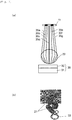
Figs. 6 show a conceptual diagram and a shot image of transmission of a translucent pill when diffusion light is used as illumination. - As shown in
Fig. 6(a) , light which can be received by animaging portion 11 is limited to light which moves alonglines translucent pills 22 straightly travels along theline 35d, and as the light comes close to an outer peripheral portion in the order of thelines translucent pills 22 becomes large. If light irradiated from alight emitting portion 31 is diffusion light in this manner, since irradiation angles of light are various, light irradiated from thelight emitting portion 31 reaches theimaging portion 11 at any angles of thelines translucent pills 22 are not produced, outlines of thetranslucent pills 22 are clearly shot on the transmission image which is acquired by theimaging portion 11. - When diffusion light is used as illumination,
opaque pills 21 in amedical envelope 20 are clearly shot as shown in a transmission image inFig. 6(b) . However, light passes through a transparency film of themedical envelope 20 which becomes a back ground, and light also passes through thetranslucent pills 22 depending upon a permeation rate thereof. Hence, brightness values of the back ground and thetranslucent pill 22 become almost the same. Therefore, even if the binarization processing and edge extraction processing are carried out for the shot image, it is only possible to slightly extract only the outer periphery of thetranslucent pill 22, and it is difficult to clearly distinguish from thetranslucent pill 22 the back ground. In this case, it is difficult to adjust a threshold value by binarization of the shot image, and an outline of thetranslucent pill 22 is frequently cut. Further, if the shot image is subjected to smoothing processing to remove other noises, the outline of thetranslucent pill 22 is removed like the noises. Hence, even if imaging processing is carried out, it is not possible to detect as thetranslucent pill 22. Here, the back ground means a region where pills do not exist in the shot image, and is a region which passes through only the transparency film. -
Figs. 7 show a conceptual diagram and a shot image of transmission of a translucent pill when parallel light is used as illumination. - In
Figs. 7 , to emit parallel light, anillumination portion 30 includes a parallellight converting portion 32 for converting diffusion light into parallel light and also includes alight emitting portion 31. - As shown in
Fig. 7(a) , if light irradiated from theillumination portion 30 is parallel light, since variation of irradiation angle is small, a location through which light cannot pass is generated in thetranslucent pill 22. Light having an angle which is close to the irradiation angle like theline 35d reaches theimaging portion 11. However, in the case of light having the angles like thelines light converting portion 32 does not have an angle, light which enters theimaging portion 11 becomes weak, and a brightness value of the outer periphery of thetranslucent pill 22 becomes low. - Hence, as shown in
Fig. 7(b) , a brightness value of a center of thetranslucent pill 22 becomes high and a brightness value of the outer periphery becomes low. Therefore, an outline of thetranslucent pill 22 is clearly shot on the transmission image which is acquired by theimaging portion 11. -
Fig. 8 is a diagram for explaining parallel light which is irradiated from an illumination portion. - As shown in
Fig. 8 , out of parallel light which is irradiated from theillumination portion 30, light (lines lines 36b to 36f) which passes through a transparent pill, light which passes through the outer periphery of thetranslucent pill 22 is refracted significantly. Therefore, such light does not reach theimaging portion 11, and a brightness value of the outer periphery of thetranslucent pill 22 is lowered. On the other hand, in the case of light which passes through a location in the vicinity of the center of thetranslucent pill 22, since a degree of refraction thereof is small, theimaging portion 11 receives the light and a brightness value becomes high. - Here, since a refraction index is determined by curvature of the
translucent pill 22, a brightness value of the outer periphery of thetranslucent pill 22 becomes low irrespective of a permeation rate of thetranslucent pill 22. By utilizing the fact that the brightness value of the outer periphery of thetranslucent pill 22 is lowered by the parallel light, it is possible to clearly distinguish thetranslucent pill 22 and the back ground from each other, and to precisely detect thetranslucent pill 22. - Irradiation of parallel light is described in patent document 1.
- [PATENT DOCUMENT 1]
Japanese Patent Application Laid-open No.2008-18230 - If parallel light is used, it is possible to clarify an outline of the
translucent pill 22 as compared with a case where diffusion light is used. - However, when the
translucent pill 22 exists directly below theimaging portion 11, the outline can be clarified, but when thetranslucent pill 22 exists at a position deviated from directly below theimaging portion 11, deviation is generated in the outline. -
Fig. 9(a) is an explanatory diagram when thetranslucent pill 22 exists at the position deviated from directly below theimaging portion 11, andFig. 9(b) is a shot image. - As shown in
Fig. 9(b) , when an imaging position (shooting position, hereinafter) is deviated from below theimaging portion 11 in the vertical direction, deviation is generated in the outline of thetranslucent pill 22, and a case where the outline cannot be recognized by this deviation is generated. - Hence, it is an object of the present invention to provide a pill inspection apparatus and a pill inspection method capable of inspecting a translucent pill irrespective of a permeation rate by obtaining a uniform outline of the translucent pill irrespective of a shooting position.
- A first aspect of the present invention provides a pill inspection apparatus including: an illumination portion for irradiating light to a medical envelope in which at least a translucent pill is enclosed; an imaging portion for acquiring a transmission image of the irradiated medical envelope; and an image processing portion for detecting, as the translucent pill, a pill having a brightness value of its outer periphery lower than that of its center using the transmission image, wherein the illumination portion includes a light emitting portion, and a light-collecting portion for collecting the light is provided between the light emitting portion and the medical envelope.
- According to a second aspect of the invention, in the pill inspection apparatus of the first aspect, the light emitting portion emits diffusion light, and a parallel light converting portion for converting the diffusion light into parallel light is provided between the light emitting portion and the light-collecting portion.
- According to a third aspect of the invention, in the pill inspection apparatus of the second aspect, the light-collecting portion is a convex lens or a Fresnel lens.
- According to a fourth aspect of the invention, in the pill inspection apparatus of the any one of first to third aspects, a domical illumination portion is provided between the medical envelope and the imaging portion.
- A fifth aspect of the present invention provides a pill inspection method including: a step of irradiating light to a medical envelope in which at least a translucent pill is enclosed to acquire a transmission image; a step of detecting, as the translucent pill, a pill having a brightness value of its outer periphery lower than that of its center using the transmission image; and a step of collecting the light from an illumination portion into an imaging portion.
- According to the present invention, it is possible to provide a pill inspection apparatus and a pill inspection method capable of inspecting a translucent pill irrespective of a permeation rate by obtaining a uniform outline of the translucent pill irrespective of a shooting position.
-
-
Fig. 1 is a block diagram showing a pill inspection apparatus according to an embodiment of the present invention; -
Fig. 2 is a perspective view of a parallel light converting portion used in the pill inspection apparatus; -
Fig. 3(a) is a conceptual diagram of transmission of translucent pills when light is collected at an image unit, andFig. 3(b) is a diagram showing transmission image of shot translucent pills; -
Figs. 4 are conceptual diagrams of transmission of translucent pills when a domical illumination shown inFig. 1 is provided; -
Fig. 5 is a flowchart showing a method to inspect a pill using the pill inspection apparatus of the embodiment; -
Figs. 6 are a conceptual diagram and a shot image of transmission of translucent pills when diffusion light is used as illumination; -
Figs. 7 are a conceptual diagram and a shot image of transmission of the translucent pills when parallel light is used as illumination; -
Fig. 8 is a diagram for explaining parallel light irradiated from an illumination portion; and -
Figs. 9 are an explanatory diagram and a shot image when the translucent pills exists at a position deviated from a location below an imaging portion in the vertical direction. - A pill inspection apparatus according to a first aspect of the present invention includes a light-collecting portion for collecting the light is provided between the light emitting portion and the medical envelope. According to this aspect, it is possible to inspect a translucent pill irrespective of a permeation rate by obtaining a uniform outline of the translucent pill irrespective of a shooting position.
- According to a second aspect, in the pill inspection apparatus of the first aspect, the light emitting portion emits diffusion light, and a parallel light converting portion for converting the diffusion light into parallel light is provided between the light emitting portion and the light-collecting portion. According to this aspect, by collecting the parallel light after the diffusion light is converted into the parallel light, it is possible to obtain a uniform outline of the translucent pill.
- According to a third aspect, in the pill inspection apparatus of the second aspect, the light-collecting portion is a convex lens or a Fresnel lens. According to this aspect, by using the Fresnel lens, it is possible to shorten a distance between an illumination portion and the medical envelope.
- According to a fourth aspect, in the pill inspection apparatus of any one of the first to third aspects, a domical illumination portion is provided between the medical envelope and the imaging portion. According to this aspect, even if the domical illumination is provided, it is possible to obtain a uniform outline of the translucent pill without being influenced by the domical illumination.
- A pill inspection method according to a fifth aspect of the present invention includes a step of irradiating light to a medical envelope in which at least a translucent pill is enclosed to acquire a transmission image; a step of detecting, as the translucent pill, a pill having a brightness value of its outer periphery lower than that of its center using the transmission image; and a step of collecting the light from an illumination portion into an imaging portion. According to this aspect, it is possible to inspect a translucent pill irrespective of a permeation rate by obtaining a uniform outline of the translucent pill irrespective of a shooting position.
- An embodiment of the present invention will be described together with the drawings.
-
Fig. 1 is a block diagram showing a pill inspection apparatus according to the embodiment of the invention, andFig. 2 is a perspective view of a parallel light converting portion used in the pill inspection apparatus. The same reference symbols are allocated to the same constituent elements, and explanation thereof will be omitted in some cases. For ease of comprehension, the drawings are illustrated schematically mainly based on the respective constituent elements. - The pill inspection apparatus inspects whether appropriate pills are enclosed in a
medical envelope 20 in accordance with prescription. Pills according to the prescription are enclosed in themedical envelope 20 by a pill packaging machine (not shown). - As shown in
Fig. 1 , to carry out an inspection operation, the pill inspection apparatus acquires an image of themedical envelope 20 including an opaque pill and a translucent pill by animaging portion 11. Animage processing portion 12 counts the number of pills based on the image of themedical envelope 20 acquired by theimaging portion 11, brings the counted number and the number of pills described in the prescription into check, and determines whether the pills are appropriately enclosed in themedical envelope 20. A camera portion is used as theimaging portion 11 for example. Theimaging portion 11 acquires a transmission image of themedical envelope 20 into which light is irradiated from anillumination portion 30. Theimaging portion 11 includes an image element and a lens. A mounting table 13 conveys themedical envelope 20. - The mounting table 13 includes a
guide portion 15 provided on an end of a mounting surface. Themedical envelope 20 is mounted on the mounting surface. The mounting table 13 also includes atransparent plate 16 through which light of theillumination portion 30 passes. Theguide portion 15 is provided therein with a drive roller and a guide roller (both not shown). An end of themedical envelope 20 is sandwiched between the drive roller and the guide roller, and the drive roller is rotated. According to this, themedical envelope 20 is moved along theguide portion 15. The mounting table 13 is placed between theimaging portion 11 and theillumination portion 30. - The
imaging portion 11 is opposed to the mounting surface of the mounting table 13 on which themedical envelope 20 is mounted, and theimaging portion 11 is located above theillumination portion 30. Theimaging portion 11 shots, from above, an image of themedical envelope 20 into which light is irradiated from below the mounting surface, and acquires a transmission image of themedical envelope 20. - A
display portion 14 is connected to theimage processing portion 12, and displays an image of pills detected by theimage processing portion 12. Hence, a tester (examiner) can visually inspects using thedisplay portion 14. - A
domical illumination portion 40 is provided below theimaging portion 11 and above thetransparent plate 16. Themedical envelope 20 is irradiated with light from thedomical illumination portion 40, and themedical envelope 20 is shot by thecamera unit 11. - The
illumination portion 30 irradiates, with light, themedical envelope 20 enclosing thetranslucent pills 22 and theopaque pills 21. Theillumination portion 30 includes alight emitting portion 31 which emits diffusion light, a parallellight converting portion 32 which converts diffusion light into parallel light, and a light-collectingportion 33 which collects parallel light. A LED which is mounted to a diffusion plate is used as thelight emitting portion 31. A convex lens or a Fresnel lens is used as the light-collectingportion 33. - A distance from the
imaging portion 11 to the light-collectingportion 33 is equal to a focal distance of the light-collectingportion 33. In this embodiment, light is collected by the light-collectingportion 33 after diffusion light is converted into the parallel light by the parallellight converting portion 32. Alternatively, light diffused from a single light source may be collected. In this case, the distance from theimaging portion 11 to the light-collectingportion 33 is equal to a half of the focal distance of the light-collectingportion 33. - The
opaque pills 21 which block light andtranslucent pills 22 through which light passes with a constant transmission factor are enclosed in themedical envelope 20. - The
opaque pill 21 blocks light. Many of general pills areopaque pills 21. - Each of the
translucent pills 22 encloses medicinal solution with a transparent film. Hence a degree of transmission of light differs depending upon a degree of transmission of the medicinal solution. Since thetranslucent pill 22 encloses the medicinal solution, thetranslucent pill 22 has a roundish shape such as a ball shape, a spheroid shape and a capsule shape. - The
medical envelope 20 includes a pastedboard region 20a having a permeation rate lower than that of the transparency film so that information is printed. Themedical envelope 20 also includesnon-pasted board regions 20b of transparency films. - As shown in
Fig. 1 , theimaging portion 11 acquires a transmission image of themedical envelope 20. The transmission image includestranslucent pills 22 having low brightness values of an obtained outer periphery. Utilizing the fact that the brightness value of the outer periphery of thetranslucent pill 22 becomes low, theimage processing portion 12 detects an outline of thetranslucent pill 22 from the transmission image of themedical envelope 20. - After the pill inspection apparatus acquires the transmission image of the
medical envelope 20 by theimaging portion 11, the pill inspection apparatus detectstranslucent pills 22 included in the transmission image of themedical envelope 20 and detectsopaque pills 21 included in the transmission image of themedical envelope 20. The number of pills of the prescription and a sum of the number of detectedtranslucent pills 22 and the number of detectedopaque pills 21 are compared with each other, and it is determined whether an appropriate number of pills exist in themedical envelope 20, thereby checking the number of pills. The pill inspection apparatus inspects the pills in such a method. Details of the checking operation of the number of pills carried out by the pill inspection apparatus will be described based on a flowchart shown inFig. 5 . - As shown in
Fig. 2 , the parallellight converting portion 32 converts diffusion light into parallel light. The parallellight converting portion 32 is formed oflaminated bodies transmission bands 32a through which visible light passes andabsorption belts 32b which absorb visible light. Here, thelaminated body 32c and thelaminated body 32d are superposed on each other such that a laminating direction of thetransmission band 32a and theabsorption belt 32b of thelaminated body 32c and a laminating direction of thetransmission band 32a and theabsorption belt 32b of thelaminated body 32d intersect with each other at right angles. Out of diffusion light which is emitted from thelight emitting portion 31, only light which enters at a predetermined incident angle passes through the parallellight converting portion 32, and the parallellight converting portion 32 absorbs light which enters at incident angles other than the former incident angle. Since only the light having the predetermined incident angle passes through the parallellight converting portion 32, light radiated from the parallellight converting portion 32 becomes parallel light. This parallel light is collected by the light-collectingportion 33. A louvered film can be used as the parallellight converting portion 32. - Next, a reason why the
translucent pills 22 can precisely be detected using the transmission image of themedical envelope 20 acquired by theimaging portion 11 will be described. -
Fig. 3(a) is a conceptual diagram of transmission of thetranslucent pills 22 when light is collected at theimaging portion 11, andFig. 3(b) is a diagram showing transmission image of the shottranslucent pills 22. -
Fig. 3(a) shows atranslucent pill 22A located directly below theimaging portion 11 in the vertical direction, and atranslucent pill 22B located at a position deviated from directly below theimaging portion 11 in the vertical direction. - Each of the
translucent pills 22 has a roundish shape. Hence, thetranslucent pill 22 plays a role as a lens, light passing through the outer periphery of thetranslucent pill 22 is refracted, and light passing through a center thereof straightly travels. - At the
translucent pill 22A located directly below theimaging portion 11 in the vertical direction, light passing through the center reaches theimaging portion 11 and its brightness value becomes high like the parallel light, but light passing through the outer periphery which enters theimaging portion 11 becomes weak, and its brightness value becomes low. Thetranslucent pill 22 has a roundish shape such as a ball shape, a spheroid shape and a capsule shape, and a refraction index thereof is gradually varied from the outer periphery toward the center of thetranslucent pill 22. Therefore, the outer periphery where the brightness value becomes low has a width of a certain level. A shape of a region having the low brightness value matches with an outline shape of thetranslucent pill 22. Therefore, image processing for comparing the shapes, e.g., image processing such as pattern matching becomes easy. - At the
translucent pill 22B located at the position deviated from directly below theimaging portion 11 in the vertical direction, its outline is deviated as shown inFigs. 9 in the case of the parallel light. In this embodiment, however, all of light passing through thetranslucent pill 22B travels toward theimaging portion 11, its outline is not deviated, light passing through the center reaches theimaging portion 11, a brightness value thereof becomes high, light passing through the outer periphery which enters theimaging portion 11 becomes weak and its brightness value becomes low. -
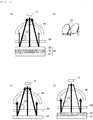
Figs. 4 are conceptual diagrams of transmission of translucent pills when the domical illumination shown inFig. 1 is provided,Fig. 4(a) shows the present embodiment where light is collected by the imaging portion andFig. 4(b) shows a transmission image of the translucent pills.Fig. 4(c) shows a comparative example using diffusion light, andFig. 4(d) shows a comparative example using parallel light. In the drawings, thickness of arrows shows intensity of light. - In
Fig. 4(a) , since light is collected at theimaging portion 11 by the light-collectingportion 33, light from the light-collectingportion 33 is not reflected by thedomical illumination portion 40 so often. Since the amount of light reflected from thedomical illumination portion 40 is small, a feature of illumination using parallel light, i.e., a feature that a brightness value of the center of thetranslucent pill 22 is high and a brightness value of the outer periphery is low is emphasized. - On the other hand, in the comparative example using diffusion light shown in
Fig. 4(c) and in the comparative example using parallel light shown inFig. 4(d) , since a periphery of thedomical illumination portion 40 is illuminated with strong light, such light is reflected by thedomical illumination portion 40. Hence,translucent pill 22 is also illuminated with such the reflection light from thedomical illumination portion 40, and a brightness value of the entiretranslucent pill 22 becomes high. According to this, the feature of illumination using parallel light, i.e., the feature that the brightness value of the center of thetranslucent pill 22 is high and the brightness value of the outer periphery is low becomes weak due to the fact that the brightness value of the entiretranslucent pill 22 becomes high, and it becomes difficult to detect thetranslucent pill 22. - In the case of the transmission image of the present embodiment obtained by collecting light at the
imaging portion 11, an outline of theopaque pill 21 located at a position away from directly below theimaging portion 11 in the vertical direction is also clear, and the outline of the outer periphery of thetranslucent pill 22 is also uniform and clear. Hence, theimage processing portion 12 can easily detect the outlines of theopaque pill 21 and thetranslucent pill 22 by the transmission image. In this embodiment, detection of thetranslucent pill 22 is carried out by pattern matching between the transmission image and sample images of thetranslucent pills 22, and the number of detectedtranslucent pills 22 is calculated. Further, since images of theopaque pill 21 and thetranslucent pill 22 are different from each other due to a difference in the transmission factor, it is possible to clearly distinguish between theopaque pill 21 and thetranslucent pill 22 in this embodiment. - Before the pattern matching between the transmission image and the sample image of the
translucent pill 22 is carried out, theimage processing portion 12 carries out a thinning operation and edge extraction by an extreme value with respect to the transmission image, and detects an outline of thetranslucent pill 22 by the transmission image. By carrying out the thinning operation and edge extraction by the extreme value with respect to the transmission image in this manner, noise is removed, and the outline of the pill is clarified. Here, the brightness value of the outer periphery of thetranslucent pill 22 is low and its width is constant as described above. However, if parallel light in which light is not collected is used, a refraction index of light which reaches theimaging portion 11 is changed depending upon an attitude of the pill and a relative position from theimaging portion 11. Hence, even if a kind of pills is the same, a wide portion and a narrow portion of the outer periphery having the low brightness value are generated. By collecting parallel light, influence of a relative position from theimaging portion 11 is reduced, and a width of the outer periphery having a low brightness value becomes uniform. At the time of detection of thetranslucent pill 22 such as the pattern matching, since the width of the outer periphery becomes uniform, it is possible to minimize adverse influence such as cut of the outline of thetranslucent pill 22. Since the refraction index of thetranslucent pill 22 from the center to the outer periphery is changed in stages, the brightness value of the outer periphery of thetranslucent pill 22 is changed from the center in stages. Concerning the outermost side of thetranslucent pill 22, however, the brightness value is changed extremely. Therefore, when the transmission image is subjected to the differential processing to extract an edge, the thinning operation for leaving only an extreme value having a large changing amount is carried out. According to this, it is possible to leave only the outermost outer periphery. Concerning the outermost outer periphery, i.e., the outline of thetranslucent pill 22, since a size of the outline is also determined by a size of each of the pills, stable pattern matching which is not influence by a position and an attitude of the pill can be realized. - Here, the
medical envelope 20 includes a pastedboard region 20a having a permeation rate lower than that of the transparency film for printing, and anon-pasted board region 20b of the transparency film. In the pastedboard region 20a, if thetranslucent pill 22 exists on a boundary between the pastedboard region 20a and thenon-pasted board region 20b for weakening light of theillumination portion 30, a brightness value of onetranslucent pill 22 differs on the side of the pastedboard region 20a and on the side of thenon-pasted board region 20b. As a result, if attempt is made to detect the outline of thetranslucent pill 22, the outline is erroneously detected in some cases. Hence, when the outline of thetranslucent pill 22 is detected by the transmission image of themedical envelope 20, the transmission image of themedical envelope 20 is divided into the pastedboard region 20a and thenon-pasted board region 20b, and the outline of thetranslucent pill 22 is detected using two threshold values, i.e., a pasted board region threshold value for detecting the outline of thetranslucent pill 22 by the pastedboard region 20a, and a non-pasted board region threshold value for detecting the outline of thetranslucent pill 22 by thenon-pasted board region 20b. - If the
image processing portion 12 uses the two threshold values for detecting the outline of thetranslucent pill 22 in this manner, even if thetranslucent pills 22 exist in the pastedboard region 20a and thenon-pasted board region 20b, thetranslucent pills 22 can be detected as one pill. - When the
image processing portion 12 extracts the edge, theimage processing portion 12 recognizes the longest line and the second longest as a boundary line of the pastedboard region 20a, and recognizes a space between these two lines as the pastedboard region 20a. Since the pastedboard region 20a is formed as a wide range so that it is easy to notice, it is possible to easily discriminate the pastedboard region 20a by detecting the longest line and the second longest line. - Next, a pill inspection method which is carried out by using the above-described pill inspection apparatus will be described.
-
Fig. 5 is a flowchart showing the pill inspection method using the pill inspection apparatus of the present embodiment. - First, the pill inspection apparatus collects parallel light from the parallel
light converting portion 32 at theimaging portion 11 by the light-collectingportion 33, the pill inspection apparatus irradiates the parallel light to themedical envelope 20 including thetranslucent pill 22, and acquires the transmission image including thetranslucent pill 22 having a low brightness value of the outer periphery (step S01). Here, the transmission image includes an image of theopaque pill 21 and an image of thetranslucent pill 22. - Next, the pill inspection apparatus detects the
translucent pills 22 by the transmission image. To calculate a threshold value for detecting thetranslucent pill 22, the pill inspection apparatus carries out the edge extraction processing by a Canny method for the transmission image of themedical envelope 20. Straight lines are extracted by haugh conversion from the edge image obtained by the edge extraction processing. Out of straight lines obtained by the straight line extraction, the longest two straight lines extending in the longitudinal direction of the pastedboard region 20a are combined as one group, and an interior thereof is extracted as the pastedboard region 20a. A mode value of the pastedboard region 20a and a mode value of a pixel other than the pastedboard region 20a are compared with each other, and a threshold value for extracting the edge of step S03 is calculated by the ratio (step S02). To clarify the outlines of theopaque pill 21 and thetranslucent pill 22, the pill inspection apparatus carries out the thinning operation for the transmission image of themedical envelope 20 by the edge extraction by the Canny method and the extreme value (step S03). In step S03, thetranslucent pills 22 are detected by pattern matching with respect to the sample image from the edge extraction image which is subjected to the edge extraction. More specifically, a sample image of only the outline is prepared by theimage processing portion 12 from a size of thetranslucent pill 22 described in a prescription, pattern matching is carried out between the sample image and the edge image of the transmission image of themedical envelope 20, and thetranslucent pills 22 are detected from the transmission image. The number of the detectedtranslucent pills 22 is calculated as the number of the translucent pills 22 (step S04). From step S01 to step S04, the number oftranslucent pills 22 enclosed in themedical envelope 20 can precisely be calculated. - Next, the pill inspection apparatus detects the
opaque pills 21. First, thetranslucent pills 22 are removed from the transmission image of the medical envelope 20 (step S05). Next, the transmission image from which thetranslucent pills 22 are removed is binarized (step S06). The number ofopaque pills 21 is calculated from the binarized transmission image by corner extraction. Since theopaque pills 21 are left in the transmission image of the binarizedmedical envelope 20, the number of calculated pills becomes equal to the number of opaque pills 21 (step S07). - Next, the number of pills of the prescription and a sum of the number of the detected
translucent pills 22 and the number of the detectedopaque pills 21 are compared with each other, and it is determined whether an appropriate number of pills exist in the medical envelope 20 (step S08). By determining whether the sum of the number oftranslucent pills 22 calculated in step S04 and the number ofopaque pills 21 calculated in step S07 is the appropriate number, the number of pills is checked. From step S01 to step S08, the total number of pills enclosed in themedical envelope 20 is calculated. - In this manner, the pill inspection apparatus can inspect the
translucent pills 22 irrespective of the permeation rate of thetranslucent pills 22. - In the above-described pill inspection apparatus, to irradiate light to the
medical envelope 20, thelight emitting portion 31, the parallellight converting portion 32 and the light-collectingportion 33 are combined with each other to form theillumination portion 30. However, this is only one example, and the light-collectingportion 33 may be formed by using Fresnel lens as the transparent plate. It is possible to use a honeycomb board as the parallellight converting portion 32 other than the louvered film. It is possible to irradiate parallel light from thelight emitting portion 31 at a position away from themedical envelope 20 more than 1 m without using the parallellight converting portion 32. - If attempt is made to detect the
translucent pill 22 by pattern matching from the transmission image, when there exist anopaque pill 21 and atranslucent pill 22 having similar shape of their outer peripheries, theopaque pill 21 is detected as thetranslucent pill 22 in some cases. Hence, to precisely detect thetranslucent pill 22, it is preferable that theimage processing portion 12 detects, as thetranslucent pill 22, a pill having a pixel having a high brightness value at a center of the detected pill in the transmission image. - If the pill inspection apparatus in this embodiment is used, a pixel having a high brightness value necessarily exits at the center of the
translucent pill 22. Hence, even if a shape of theopaque pill 21 and a shape of a sample image of thetranslucent pill 22 are the same, if a pixel having a high brightness value does not exist at the center of the pill, the pill inspection apparatus determines this pill as theopaque pill 21, and if a pixel having a high brightness value exists at the center of the pill, the pill inspection apparatus may determine this pill as thetranslucent pill 22. - According to this, it is possible to detect the
opaque pill 21 and thetranslucent pill 22 distinctively. - The pill inspection apparatus and the pill inspection method of the present invention are useful in a pharmacy and a hospital where a preparation operation of a medicine must be carried out.
-
- 11
- imaging portion
- 12
- image processing portion
- 13
- mounting table
- 14
- display portion
- 15
- guide portion
- 16
- transparent plate
- 20
- medical envelope
- 20a
- pasted board region
- 20b
- non-pasted board region
- 21
- opaque pill
- 22
- translucent pill
- 30
- illumination portion
- 31
- light emitting portion
- 32
- parallel light converting portion
- 33
- light-collecting portion
- 40
- domical illumination portion
Claims (5)
- A pill inspection apparatus comprising:an illumination portion for irradiating light to a medical envelope in which at least a translucent pill is enclosed;an imaging portion for acquiring a transmission image of the irradiated medical envelope; andan image processing portion for detecting, as the translucent pill, a pill having a brightness value of its outer periphery lower than that of its center using the transmission image, whereinthe illumination portion includes a light emitting portion, and a light-collecting portion for collecting the light is provided between the light emitting portion and the medical envelope.
- The pill inspection apparatus according to claim 1, wherein the light emitting portion emits diffusion light, and a parallel light converting portion for converting the diffusion light into parallel light is provided between the light emitting portion and the light-collecting portion.
- The pill inspection apparatus according to claim 2, wherein the light-collecting portion is a convex lens or a Fresnel lens.
- The pill inspection apparatus according to any one of claims 1 to 3, wherein a domical illumination portion is provided between the medical envelope and the imaging portion.
- A pill inspection method comprising:a step of irradiating light to a medical envelope in which at least a translucent pill is enclosed to acquire a transmission image;a step of detecting, as the translucent pill, a pill having a brightness value of its outer periphery lower than that of its center using the transmission image; anda step of collecting the light from an illumination portion into an imaging portion.
Applications Claiming Priority (2)
| Application Number | Priority Date | Filing Date | Title |
|---|---|---|---|
| JP2013107641 | 2013-05-22 | ||
| PCT/JP2014/002042 WO2014188650A1 (en) | 2013-05-22 | 2014-04-09 | Pill inspection device and pill inspection method |
Publications (3)
| Publication Number | Publication Date |
|---|---|
| EP3000458A1 true EP3000458A1 (en) | 2016-03-30 |
| EP3000458A4 EP3000458A4 (en) | 2016-05-18 |
| EP3000458B1 EP3000458B1 (en) | 2020-02-19 |
Family
ID=51933223
Family Applications (1)
| Application Number | Title | Priority Date | Filing Date |
|---|---|---|---|
| EP14801582.9A Active EP3000458B1 (en) | 2013-05-22 | 2014-04-09 | Pill inspection device and pill inspection method |
Country Status (5)
| Country | Link |
|---|---|
| US (1) | US9958400B2 (en) |
| EP (1) | EP3000458B1 (en) |
| JP (1) | JP6379088B2 (en) |
| CN (1) | CN105208995B (en) |
| WO (1) | WO2014188650A1 (en) |
Families Citing this family (8)
| Publication number | Priority date | Publication date | Assignee | Title |
|---|---|---|---|---|
| JP6100136B2 (en) * | 2013-09-30 | 2017-03-22 | 富士フイルム株式会社 | Drug recognition apparatus and method |
| EP3367103A1 (en) | 2017-02-28 | 2018-08-29 | Sotax Ag | Device and method for determining at least one physical parameter of pharmaceutical products |
| JP6757851B2 (en) * | 2017-05-30 | 2020-09-23 | 富士フイルム富山化学株式会社 | Dispensing audit support device and dispensing audit support method |
| CN108154154B (en) * | 2017-11-13 | 2022-03-29 | 广东三维家信息科技有限公司 | Method for detecting number of traditional Chinese medicine tablets in regular grids |
| JP6998048B2 (en) * | 2018-03-09 | 2022-01-18 | エイチエスティ・ビジョン株式会社 | Image processing system |
| CN110208267B (en) * | 2019-06-21 | 2020-06-02 | 中国海洋大学 | Marine organism bidirectional optical field in-situ observation method suitable for targets with different transmittances |
| JP7746074B2 (en) * | 2021-08-31 | 2025-09-30 | 日立チャネルソリューションズ株式会社 | Drug inspection device and drug inspection method |
| DE102022110826A1 (en) * | 2022-05-03 | 2023-11-09 | Tt Innovation Ag | Device for manipulating bags containing containers |
Family Cites Families (25)
| Publication number | Priority date | Publication date | Assignee | Title |
|---|---|---|---|---|
| JPS5657939A (en) * | 1979-10-16 | 1981-05-20 | Paaku Deebisu Kk | Inspecting device for medical capsule |
| JPH01143904A (en) * | 1987-11-30 | 1989-06-06 | Toshiba Corp | Thin film inspecting device |
| JPH05215908A (en) * | 1992-02-03 | 1993-08-27 | Hitachi Ltd | Louver film filter and display device mounted with the same |
| US7148960B2 (en) * | 1999-06-10 | 2006-12-12 | Aradigm Corporation | Method and device for non-destructive analysis of perforations in a material |
| US6624885B1 (en) * | 1999-06-10 | 2003-09-23 | Aradigm Corporation | Method and device for non-destructive analysis of perforation in a material |
| IE20000790A1 (en) * | 1999-10-01 | 2001-04-18 | Stockeryale Irl Ltd | Linear illumination |
| US6867851B2 (en) * | 1999-11-04 | 2005-03-15 | Regents Of The University Of Minnesota | Scanning of biological samples |
| JP2003130799A (en) * | 2001-10-26 | 2003-05-08 | Ccs Inc | Illumination apparatus for inspection |
| JP4300809B2 (en) | 2003-01-28 | 2009-07-22 | パナソニック電工株式会社 | Inspection apparatus and inspection method for granular object |
| JP4523474B2 (en) | 2005-04-06 | 2010-08-11 | シーケーディ株式会社 | Defect inspection device and PTP packaging machine |
| US7193697B2 (en) * | 2005-07-25 | 2007-03-20 | Chroma Ate Inc. | Apparatus for feature detection |
| JP4256434B2 (en) | 2006-06-14 | 2009-04-22 | 株式会社 タフティ | Method and device for testing packaged medicine |
| WO2008121692A1 (en) | 2007-03-30 | 2008-10-09 | University Of South Carolina | Tablet analysis and measurement system |
| JP5222682B2 (en) * | 2008-09-30 | 2013-06-26 | 晋一 直箟 | Drug imaging storage device |
| JP5163985B2 (en) * | 2008-11-14 | 2013-03-13 | 学校法人早稲田大学 | Granular product type inspection device |
| JP5680277B2 (en) * | 2009-02-02 | 2015-03-04 | 株式会社ミューチュアル | Solid product inspection equipment |
| DE102010021853B4 (en) | 2010-05-28 | 2012-04-26 | Isra Vision Ag | Device and method for optical inspection of an object |
| JP5351980B2 (en) * | 2010-07-09 | 2013-11-27 | パナソニック株式会社 | Tablet inspection support method and tablet inspection support device |
| JP5747150B2 (en) | 2010-10-05 | 2015-07-08 | パナソニックIpマネジメント株式会社 | Tablet inspection device and tablet inspection method |
| JP5886209B2 (en) * | 2010-12-17 | 2016-03-16 | パナソニックヘルスケアホールディングス株式会社 | Tablet inspection device |
| US20130058550A1 (en) * | 2011-03-24 | 2013-03-07 | Takanobu Tanimoto | Tablet inspection apparatus and tablet inspection method using the same |
| JP5414917B2 (en) * | 2011-07-13 | 2014-02-12 | パナソニック株式会社 | Tablet inspection device and tablet inspection method |
| WO2013021543A1 (en) * | 2011-08-08 | 2013-02-14 | パナソニック株式会社 | Medication package checking system |
| JP5942242B2 (en) * | 2011-10-20 | 2016-06-29 | 株式会社目白ゲノッセン | Inspection lighting device |
| JP2013228254A (en) * | 2012-04-25 | 2013-11-07 | Hitachi High-Technologies Corp | Optical surface flaw inspection device and optical surface flaw inspection method |
-
2014
- 2014-04-09 US US14/892,870 patent/US9958400B2/en not_active Expired - Fee Related
- 2014-04-09 JP JP2015518055A patent/JP6379088B2/en active Active
- 2014-04-09 CN CN201480025383.6A patent/CN105208995B/en not_active Expired - Fee Related
- 2014-04-09 EP EP14801582.9A patent/EP3000458B1/en active Active
- 2014-04-09 WO PCT/JP2014/002042 patent/WO2014188650A1/en not_active Ceased
Also Published As
| Publication number | Publication date |
|---|---|
| US20160109385A1 (en) | 2016-04-21 |
| CN105208995B (en) | 2020-01-14 |
| JPWO2014188650A1 (en) | 2017-02-23 |
| US9958400B2 (en) | 2018-05-01 |
| JP6379088B2 (en) | 2018-08-22 |
| EP3000458A4 (en) | 2016-05-18 |
| EP3000458B1 (en) | 2020-02-19 |
| CN105208995A (en) | 2015-12-30 |
| WO2014188650A1 (en) | 2014-11-27 |
Similar Documents
| Publication | Publication Date | Title |
|---|---|---|
| US9958400B2 (en) | Pill inspection apparatus and pill inspection method | |
| JP5414917B2 (en) | Tablet inspection device and tablet inspection method | |
| JP5496348B2 (en) | Tablet inspection apparatus and tablet inspection method using the same | |
| JP6199042B2 (en) | Container inspection equipment | |
| US9638579B2 (en) | Method and system for checking the color quality of preforms | |
| CN111902843B (en) | Drug determination device and boundary concave portion detection method | |
| KR101762165B1 (en) | Appearance inspection device | |
| CN112673249B (en) | Inspection device, PTP packaging machine, and method for manufacturing PTP sheet | |
| CN107615394B (en) | Medicine dispensing monitoring device, medicine dispensing monitoring method, and recording medium | |
| US7382910B2 (en) | Method of analysing a stack of flat objects | |
| CN109313144B (en) | Method and system for inspecting equipment for optical inspection of glass containers | |
| JP2013148454A (en) | Tablet checking apparatus | |
| KR102362846B1 (en) | Inspection device, PTP packaging machine, and method of manufacturing PTP sheet | |
| US9547784B1 (en) | Sensor arrangement | |
| WO2020066251A1 (en) | Inspection apparatus, ptp packaging machine, and method for manufacturing ptp sheet | |
| KR20090083843A (en) | Method and apparatus for pattern inspection | |
| WO2016063381A1 (en) | Inspection device using electromagnetic wave detection unit and optical detection unit | |
| CN101175990B (en) | Method for inspecting granular objects and inspection device for implementing the method | |
| TW201312095A (en) | Transparent electrode observation device and transparent electrode observation method | |
| CN113811761B (en) | Inspection device and packaging body manufacturing device | |
| JP2006300875A (en) | Liquid level detecting method, liquid amount detecting method, liquid level detector, liquid amount detector, and dispensing device | |
| KR102459635B1 (en) | An X-Ray Detecting Type of a Component Counter and a Method for Counting Components Using the Same | |
| JP2014095652A (en) | Medicine identifying method and medicine identifying apparatus | |
| DE102016117262A1 (en) | Apparatus and method for telecentric inspection of an object | |
| JP4639840B2 (en) | Inspection method for granular object and inspection apparatus using the same |
Legal Events
| Date | Code | Title | Description |
|---|---|---|---|
| PUAI | Public reference made under article 153(3) epc to a published international application that has entered the european phase |
Free format text: ORIGINAL CODE: 0009012 |
|
| 17P | Request for examination filed |
Effective date: 20151222 |
|
| AK | Designated contracting states |
Kind code of ref document: A1 Designated state(s): AL AT BE BG CH CY CZ DE DK EE ES FI FR GB GR HR HU IE IS IT LI LT LU LV MC MK MT NL NO PL PT RO RS SE SI SK SM TR |
|
| AX | Request for extension of the european patent |
Extension state: BA ME |
|
| A4 | Supplementary search report drawn up and despatched |
Effective date: 20160419 |
|
| RIC1 | Information provided on ipc code assigned before grant |
Ipc: G01N 21/95 20060101AFI20160413BHEP Ipc: G01N 21/88 20060101ALI20160413BHEP Ipc: A61J 1/03 20060101ALI20160413BHEP |
|
| DAX | Request for extension of the european patent (deleted) | ||
| RAP1 | Party data changed (applicant data changed or rights of an application transferred) |
Owner name: PHC HOLDINGS CORPORATION |
|
| STAA | Information on the status of an ep patent application or granted ep patent |
Free format text: STATUS: EXAMINATION IS IN PROGRESS |
|
| 17Q | First examination report despatched |
Effective date: 20180905 |
|
| REG | Reference to a national code |
Ref country code: DE Ref legal event code: R079 Ref document number: 602014061265 Country of ref document: DE Free format text: PREVIOUS MAIN CLASS: A61J0003000000 Ipc: G01N0021840000 |
|
| GRAP | Despatch of communication of intention to grant a patent |
Free format text: ORIGINAL CODE: EPIDOSNIGR1 |
|
| STAA | Information on the status of an ep patent application or granted ep patent |
Free format text: STATUS: GRANT OF PATENT IS INTENDED |
|
| RIC1 | Information provided on ipc code assigned before grant |
Ipc: G01N 21/88 20060101ALI20190828BHEP Ipc: G01N 21/84 20060101AFI20190828BHEP Ipc: G01N 21/95 20060101ALI20190828BHEP Ipc: A61J 1/03 20060101ALI20190828BHEP |
|
| INTG | Intention to grant announced |
Effective date: 20190909 |
|
| GRAS | Grant fee paid |
Free format text: ORIGINAL CODE: EPIDOSNIGR3 |
|
| GRAA | (expected) grant |
Free format text: ORIGINAL CODE: 0009210 |
|
| STAA | Information on the status of an ep patent application or granted ep patent |
Free format text: STATUS: THE PATENT HAS BEEN GRANTED |
|
| AK | Designated contracting states |
Kind code of ref document: B1 Designated state(s): AL AT BE BG CH CY CZ DE DK EE ES FI FR GB GR HR HU IE IS IT LI LT LU LV MC MK MT NL NO PL PT RO RS SE SI SK SM TR |
|
| REG | Reference to a national code |
Ref country code: CH Ref legal event code: EP |
|
| REG | Reference to a national code |
Ref country code: DE Ref legal event code: R096 Ref document number: 602014061265 Country of ref document: DE |
|
| REG | Reference to a national code |
Ref country code: AT Ref legal event code: REF Ref document number: 1235533 Country of ref document: AT Kind code of ref document: T Effective date: 20200315 |
|
| REG | Reference to a national code |
Ref country code: IE Ref legal event code: FG4D |
|
| REG | Reference to a national code |
Ref country code: NL Ref legal event code: FP |
|
| REG | Reference to a national code |
Ref country code: SE Ref legal event code: TRGR |
|
| PG25 | Lapsed in a contracting state [announced via postgrant information from national office to epo] |
Ref country code: NO Free format text: LAPSE BECAUSE OF FAILURE TO SUBMIT A TRANSLATION OF THE DESCRIPTION OR TO PAY THE FEE WITHIN THE PRESCRIBED TIME-LIMIT Effective date: 20200519 Ref country code: FI Free format text: LAPSE BECAUSE OF FAILURE TO SUBMIT A TRANSLATION OF THE DESCRIPTION OR TO PAY THE FEE WITHIN THE PRESCRIBED TIME-LIMIT Effective date: 20200219 Ref country code: RS Free format text: LAPSE BECAUSE OF FAILURE TO SUBMIT A TRANSLATION OF THE DESCRIPTION OR TO PAY THE FEE WITHIN THE PRESCRIBED TIME-LIMIT Effective date: 20200219 |
|
| REG | Reference to a national code |
Ref country code: LT Ref legal event code: MG4D |
|
| PG25 | Lapsed in a contracting state [announced via postgrant information from national office to epo] |
Ref country code: BG Free format text: LAPSE BECAUSE OF FAILURE TO SUBMIT A TRANSLATION OF THE DESCRIPTION OR TO PAY THE FEE WITHIN THE PRESCRIBED TIME-LIMIT Effective date: 20200519 Ref country code: IS Free format text: LAPSE BECAUSE OF FAILURE TO SUBMIT A TRANSLATION OF THE DESCRIPTION OR TO PAY THE FEE WITHIN THE PRESCRIBED TIME-LIMIT Effective date: 20200619 Ref country code: HR Free format text: LAPSE BECAUSE OF FAILURE TO SUBMIT A TRANSLATION OF THE DESCRIPTION OR TO PAY THE FEE WITHIN THE PRESCRIBED TIME-LIMIT Effective date: 20200219 Ref country code: LV Free format text: LAPSE BECAUSE OF FAILURE TO SUBMIT A TRANSLATION OF THE DESCRIPTION OR TO PAY THE FEE WITHIN THE PRESCRIBED TIME-LIMIT Effective date: 20200219 Ref country code: GR Free format text: LAPSE BECAUSE OF FAILURE TO SUBMIT A TRANSLATION OF THE DESCRIPTION OR TO PAY THE FEE WITHIN THE PRESCRIBED TIME-LIMIT Effective date: 20200520 |
|
| PG25 | Lapsed in a contracting state [announced via postgrant information from national office to epo] |
Ref country code: ES Free format text: LAPSE BECAUSE OF FAILURE TO SUBMIT A TRANSLATION OF THE DESCRIPTION OR TO PAY THE FEE WITHIN THE PRESCRIBED TIME-LIMIT Effective date: 20200219 Ref country code: CZ Free format text: LAPSE BECAUSE OF FAILURE TO SUBMIT A TRANSLATION OF THE DESCRIPTION OR TO PAY THE FEE WITHIN THE PRESCRIBED TIME-LIMIT Effective date: 20200219 Ref country code: LT Free format text: LAPSE BECAUSE OF FAILURE TO SUBMIT A TRANSLATION OF THE DESCRIPTION OR TO PAY THE FEE WITHIN THE PRESCRIBED TIME-LIMIT Effective date: 20200219 Ref country code: RO Free format text: LAPSE BECAUSE OF FAILURE TO SUBMIT A TRANSLATION OF THE DESCRIPTION OR TO PAY THE FEE WITHIN THE PRESCRIBED TIME-LIMIT Effective date: 20200219 Ref country code: SK Free format text: LAPSE BECAUSE OF FAILURE TO SUBMIT A TRANSLATION OF THE DESCRIPTION OR TO PAY THE FEE WITHIN THE PRESCRIBED TIME-LIMIT Effective date: 20200219 Ref country code: SM Free format text: LAPSE BECAUSE OF FAILURE TO SUBMIT A TRANSLATION OF THE DESCRIPTION OR TO PAY THE FEE WITHIN THE PRESCRIBED TIME-LIMIT Effective date: 20200219 Ref country code: EE Free format text: LAPSE BECAUSE OF FAILURE TO SUBMIT A TRANSLATION OF THE DESCRIPTION OR TO PAY THE FEE WITHIN THE PRESCRIBED TIME-LIMIT Effective date: 20200219 Ref country code: DK Free format text: LAPSE BECAUSE OF FAILURE TO SUBMIT A TRANSLATION OF THE DESCRIPTION OR TO PAY THE FEE WITHIN THE PRESCRIBED TIME-LIMIT Effective date: 20200219 Ref country code: PT Free format text: LAPSE BECAUSE OF FAILURE TO SUBMIT A TRANSLATION OF THE DESCRIPTION OR TO PAY THE FEE WITHIN THE PRESCRIBED TIME-LIMIT Effective date: 20200712 |
|
| REG | Reference to a national code |
Ref country code: DE Ref legal event code: R119 Ref document number: 602014061265 Country of ref document: DE |
|
| REG | Reference to a national code |
Ref country code: AT Ref legal event code: MK05 Ref document number: 1235533 Country of ref document: AT Kind code of ref document: T Effective date: 20200219 |
|
| PG25 | Lapsed in a contracting state [announced via postgrant information from national office to epo] |
Ref country code: MC Free format text: LAPSE BECAUSE OF FAILURE TO SUBMIT A TRANSLATION OF THE DESCRIPTION OR TO PAY THE FEE WITHIN THE PRESCRIBED TIME-LIMIT Effective date: 20200219 |
|
| REG | Reference to a national code |
Ref country code: CH Ref legal event code: PL |
|
| PLBE | No opposition filed within time limit |
Free format text: ORIGINAL CODE: 0009261 |
|
| STAA | Information on the status of an ep patent application or granted ep patent |
Free format text: STATUS: NO OPPOSITION FILED WITHIN TIME LIMIT |
|
| 26N | No opposition filed |
Effective date: 20201120 |
|
| PG25 | Lapsed in a contracting state [announced via postgrant information from national office to epo] |
Ref country code: LI Free format text: LAPSE BECAUSE OF NON-PAYMENT OF DUE FEES Effective date: 20200430 Ref country code: DE Free format text: LAPSE BECAUSE OF NON-PAYMENT OF DUE FEES Effective date: 20201103 Ref country code: CH Free format text: LAPSE BECAUSE OF NON-PAYMENT OF DUE FEES Effective date: 20200430 Ref country code: AT Free format text: LAPSE BECAUSE OF FAILURE TO SUBMIT A TRANSLATION OF THE DESCRIPTION OR TO PAY THE FEE WITHIN THE PRESCRIBED TIME-LIMIT Effective date: 20200219 Ref country code: IT Free format text: LAPSE BECAUSE OF FAILURE TO SUBMIT A TRANSLATION OF THE DESCRIPTION OR TO PAY THE FEE WITHIN THE PRESCRIBED TIME-LIMIT Effective date: 20200219 Ref country code: LU Free format text: LAPSE BECAUSE OF NON-PAYMENT OF DUE FEES Effective date: 20200409 |
|
| REG | Reference to a national code |
Ref country code: BE Ref legal event code: MM Effective date: 20200430 |
|
| PG25 | Lapsed in a contracting state [announced via postgrant information from national office to epo] |
Ref country code: BE Free format text: LAPSE BECAUSE OF NON-PAYMENT OF DUE FEES Effective date: 20200430 Ref country code: SI Free format text: LAPSE BECAUSE OF FAILURE TO SUBMIT A TRANSLATION OF THE DESCRIPTION OR TO PAY THE FEE WITHIN THE PRESCRIBED TIME-LIMIT Effective date: 20200219 Ref country code: PL Free format text: LAPSE BECAUSE OF FAILURE TO SUBMIT A TRANSLATION OF THE DESCRIPTION OR TO PAY THE FEE WITHIN THE PRESCRIBED TIME-LIMIT Effective date: 20200219 |
|
| GBPC | Gb: european patent ceased through non-payment of renewal fee |
Effective date: 20200519 |
|
| PG25 | Lapsed in a contracting state [announced via postgrant information from national office to epo] |
Ref country code: GB Free format text: LAPSE BECAUSE OF NON-PAYMENT OF DUE FEES Effective date: 20200519 Ref country code: IE Free format text: LAPSE BECAUSE OF NON-PAYMENT OF DUE FEES Effective date: 20200409 |
|
| PGFP | Annual fee paid to national office [announced via postgrant information from national office to epo] |
Ref country code: FR Payment date: 20210421 Year of fee payment: 8 |
|
| PGFP | Annual fee paid to national office [announced via postgrant information from national office to epo] |
Ref country code: SE Payment date: 20210420 Year of fee payment: 8 |
|
| PGFP | Annual fee paid to national office [announced via postgrant information from national office to epo] |
Ref country code: NL Payment date: 20210421 Year of fee payment: 8 |
|
| PG25 | Lapsed in a contracting state [announced via postgrant information from national office to epo] |
Ref country code: TR Free format text: LAPSE BECAUSE OF FAILURE TO SUBMIT A TRANSLATION OF THE DESCRIPTION OR TO PAY THE FEE WITHIN THE PRESCRIBED TIME-LIMIT Effective date: 20200219 Ref country code: MT Free format text: LAPSE BECAUSE OF FAILURE TO SUBMIT A TRANSLATION OF THE DESCRIPTION OR TO PAY THE FEE WITHIN THE PRESCRIBED TIME-LIMIT Effective date: 20200219 Ref country code: CY Free format text: LAPSE BECAUSE OF FAILURE TO SUBMIT A TRANSLATION OF THE DESCRIPTION OR TO PAY THE FEE WITHIN THE PRESCRIBED TIME-LIMIT Effective date: 20200219 |
|
| PG25 | Lapsed in a contracting state [announced via postgrant information from national office to epo] |
Ref country code: MK Free format text: LAPSE BECAUSE OF FAILURE TO SUBMIT A TRANSLATION OF THE DESCRIPTION OR TO PAY THE FEE WITHIN THE PRESCRIBED TIME-LIMIT Effective date: 20200219 Ref country code: AL Free format text: LAPSE BECAUSE OF FAILURE TO SUBMIT A TRANSLATION OF THE DESCRIPTION OR TO PAY THE FEE WITHIN THE PRESCRIBED TIME-LIMIT Effective date: 20200219 |
|
| REG | Reference to a national code |
Ref country code: SE Ref legal event code: EUG |
|
| REG | Reference to a national code |
Ref country code: NL Ref legal event code: MM Effective date: 20220501 |
|
| PG25 | Lapsed in a contracting state [announced via postgrant information from national office to epo] |
Ref country code: SE Free format text: LAPSE BECAUSE OF NON-PAYMENT OF DUE FEES Effective date: 20220410 Ref country code: NL Free format text: LAPSE BECAUSE OF NON-PAYMENT OF DUE FEES Effective date: 20220501 Ref country code: FR Free format text: LAPSE BECAUSE OF NON-PAYMENT OF DUE FEES Effective date: 20220430 |