EP3000425A1 - Treatment system, instrument control device, and treatment system operation method - Google Patents
Treatment system, instrument control device, and treatment system operation method Download PDFInfo
- Publication number
- EP3000425A1 EP3000425A1 EP14832700.0A EP14832700A EP3000425A1 EP 3000425 A1 EP3000425 A1 EP 3000425A1 EP 14832700 A EP14832700 A EP 14832700A EP 3000425 A1 EP3000425 A1 EP 3000425A1
- Authority
- EP
- European Patent Office
- Prior art keywords
- temperature
- section
- treatment
- energy
- living tissue
- Prior art date
- Legal status (The legal status is an assumption and is not a legal conclusion. Google has not performed a legal analysis and makes no representation as to the accuracy of the status listed.)
- Withdrawn
Links
Images






Classifications
-
- A—HUMAN NECESSITIES
- A61—MEDICAL OR VETERINARY SCIENCE; HYGIENE
- A61B—DIAGNOSIS; SURGERY; IDENTIFICATION
- A61B18/00—Surgical instruments, devices or methods for transferring non-mechanical forms of energy to or from the body
- A61B18/04—Surgical instruments, devices or methods for transferring non-mechanical forms of energy to or from the body by heating
- A61B18/08—Surgical instruments, devices or methods for transferring non-mechanical forms of energy to or from the body by heating by means of electrically-heated probes
- A61B18/082—Probes or electrodes therefor
- A61B18/085—Forceps, scissors
-
- A—HUMAN NECESSITIES
- A61—MEDICAL OR VETERINARY SCIENCE; HYGIENE
- A61B—DIAGNOSIS; SURGERY; IDENTIFICATION
- A61B18/00—Surgical instruments, devices or methods for transferring non-mechanical forms of energy to or from the body
- A61B18/04—Surgical instruments, devices or methods for transferring non-mechanical forms of energy to or from the body by heating
- A61B18/08—Surgical instruments, devices or methods for transferring non-mechanical forms of energy to or from the body by heating by means of electrically-heated probes
- A61B18/10—Power sources therefor
-
- A—HUMAN NECESSITIES
- A61—MEDICAL OR VETERINARY SCIENCE; HYGIENE
- A61B—DIAGNOSIS; SURGERY; IDENTIFICATION
- A61B18/00—Surgical instruments, devices or methods for transferring non-mechanical forms of energy to or from the body
- A61B18/04—Surgical instruments, devices or methods for transferring non-mechanical forms of energy to or from the body by heating
- A61B18/12—Surgical instruments, devices or methods for transferring non-mechanical forms of energy to or from the body by heating by passing a current through the tissue to be heated, e.g. high-frequency current
- A61B18/1206—Generators therefor
-
- A—HUMAN NECESSITIES
- A61—MEDICAL OR VETERINARY SCIENCE; HYGIENE
- A61B—DIAGNOSIS; SURGERY; IDENTIFICATION
- A61B18/00—Surgical instruments, devices or methods for transferring non-mechanical forms of energy to or from the body
- A61B18/04—Surgical instruments, devices or methods for transferring non-mechanical forms of energy to or from the body by heating
- A61B18/12—Surgical instruments, devices or methods for transferring non-mechanical forms of energy to or from the body by heating by passing a current through the tissue to be heated, e.g. high-frequency current
- A61B18/14—Probes or electrodes therefor
- A61B18/1442—Probes having pivoting end effectors, e.g. forceps
-
- A—HUMAN NECESSITIES
- A61—MEDICAL OR VETERINARY SCIENCE; HYGIENE
- A61B—DIAGNOSIS; SURGERY; IDENTIFICATION
- A61B17/00—Surgical instruments, devices or methods
- A61B17/11—Surgical instruments, devices or methods for performing anastomosis; Buttons for anastomosis
- A61B17/1114—Surgical instruments, devices or methods for performing anastomosis; Buttons for anastomosis of the digestive tract, e.g. bowels or oesophagus
-
- A—HUMAN NECESSITIES
- A61—MEDICAL OR VETERINARY SCIENCE; HYGIENE
- A61B—DIAGNOSIS; SURGERY; IDENTIFICATION
- A61B18/00—Surgical instruments, devices or methods for transferring non-mechanical forms of energy to or from the body
- A61B18/18—Surgical instruments, devices or methods for transferring non-mechanical forms of energy to or from the body by applying electromagnetic radiation, e.g. microwaves
- A61B18/20—Surgical instruments, devices or methods for transferring non-mechanical forms of energy to or from the body by applying electromagnetic radiation, e.g. microwaves using laser
-
- A—HUMAN NECESSITIES
- A61—MEDICAL OR VETERINARY SCIENCE; HYGIENE
- A61B—DIAGNOSIS; SURGERY; IDENTIFICATION
- A61B17/00—Surgical instruments, devices or methods
- A61B2017/00017—Electrical control of surgical instruments
- A61B2017/00022—Sensing or detecting at the treatment site
- A61B2017/00084—Temperature
-
- A—HUMAN NECESSITIES
- A61—MEDICAL OR VETERINARY SCIENCE; HYGIENE
- A61B—DIAGNOSIS; SURGERY; IDENTIFICATION
- A61B18/00—Surgical instruments, devices or methods for transferring non-mechanical forms of energy to or from the body
- A61B2018/00636—Sensing and controlling the application of energy
- A61B2018/00684—Sensing and controlling the application of energy using lookup tables
-
- A—HUMAN NECESSITIES
- A61—MEDICAL OR VETERINARY SCIENCE; HYGIENE
- A61B—DIAGNOSIS; SURGERY; IDENTIFICATION
- A61B18/00—Surgical instruments, devices or methods for transferring non-mechanical forms of energy to or from the body
- A61B2018/00636—Sensing and controlling the application of energy
- A61B2018/00696—Controlled or regulated parameters
- A61B2018/00702—Power or energy
-
- A—HUMAN NECESSITIES
- A61—MEDICAL OR VETERINARY SCIENCE; HYGIENE
- A61B—DIAGNOSIS; SURGERY; IDENTIFICATION
- A61B18/00—Surgical instruments, devices or methods for transferring non-mechanical forms of energy to or from the body
- A61B2018/00636—Sensing and controlling the application of energy
- A61B2018/00696—Controlled or regulated parameters
- A61B2018/00714—Temperature
-
- A—HUMAN NECESSITIES
- A61—MEDICAL OR VETERINARY SCIENCE; HYGIENE
- A61B—DIAGNOSIS; SURGERY; IDENTIFICATION
- A61B18/00—Surgical instruments, devices or methods for transferring non-mechanical forms of energy to or from the body
- A61B2018/00636—Sensing and controlling the application of energy
- A61B2018/00773—Sensed parameters
- A61B2018/00791—Temperature
Definitions
- An embodiment of the present invention relates to a treatment system including a treatment section which applies treatment energy to biological tissue, a treatment instrument control apparatus of the treatment system, and an operation method of the treatment system.
- U.S. Patent Application Publication No. 2009/076506 discloses a treatment system including a pair of clamping sections that apply high frequency power energy and thermal energy to a clamped body to be treated, a high frequency power source that outputs high frequency power for applying the high frequency power energy, a power source for heat generation that outputs heat generation power for applying the thermal energy, and a control section configured to control the high frequency power source and the power source for the heat generation in order to switch high frequency power energy application and application of the thermal energy.
- U.S. Patent Application Publication No. 2009/0248002 discloses a treatment system that applies high frequency power energy to a body to be treated, and applies thermal energy after the application of the high frequency power energy is ended.
- the high frequency power energy has a function of, by destroying cell membranes of the body to be treated, releasing intracellular components including polymer compounds typified by proteins and integrating the intracellular components with extracellular components typified by collagen. Then, the body to be treated is bonded by the application of the thermal energy.
- U.S. Patent Application Publication No. 2013/19060 discloses a treatment system that applies ultrasound energy and high frequency power energy to a body to be treated.
- U.S. Patent Application Publication No. 2005/222556 discloses a treatment system that applies light energy to a body to be treated using a laser.
- a treatment section of a medical treatment instrument applies at least one of thermal energy, ultrasound energy, light energy and high frequency power energy to a body to be treated, as treatment energy.
- control an energy amount based on a temperature of living tissue that is being treated it is preferable to control an energy amount based on a temperature of living tissue that is being treated.
- control is performed based on a temperature of an energy output section, a heating element for example, which is easy to detect, instead of the living tissue temperature.
- control is performed based on a temperature of an energy output section that is easy to detect in a conventional treatment system, it is sometimes not easy to perform appropriate treatment.
- a treatment system of an embodiment includes: a treatment instrument having an output section which applies treatment energy to living tissue; a temperature measuring section configured to measure a temperature of the output section; a power source configured to generate power for the treatment energy; a first calculating section configured to estimate a temperature difference between the temperature of the output section to which the power is applied and a temperature of the living tissue to which the treatment energy is applied, using a table or an equation stored beforehand in order to estimate the temperature difference based on an output value of the power source; a second calculating section configured to estimate the temperature of the living tissue from the temperature of the output section measured by the temperature measuring section and the temperature difference estimated by the first calculating section; and a control section configured to control the power source based on the living tissue temperature estimated by the second calculating section.
- a treatment instrument control apparatus of a different embodiment is a treatment instrument control apparatus configured to control a treatment instrument having an output section which applies treatment energy to living tissue, and includes: a power source configured to generate power for the treatment energy; a temperature measuring section configured to measure a temperature of the output section; a first calculating section configured to estimate a temperature difference between the temperature of the output section to which the power is applied and a temperature of the living tissue to which the treatment energy is applied, using a table or an equation stored beforehand in order to estimate the temperature difference based on an output value of the power source; a second calculating section configured to estimate the temperature of the living tissue from the temperature of the output section measured by the temperature measuring section and the temperature difference estimated by the first calculating section; and a control section configured to control the power source which generates the power for the treatment energy, based on the living tissue temperature estimated by the second calculating section.
- An operation method of a treatment system of a different embodiment includes: a step in which an output section of a treatment instrument starts generation of treatment energy to treat living tissue by a power source starting generation of power; a step in which a temperature measuring section measures a temperature of the output section; a step in which a first calculating section estimates a temperature difference between the temperature of the output section to which the power is applied and a temperature of the living tissue to which the treatment energy is applied, using a table or an equation stored beforehand in order to estimate the temperature difference based on an output value of the power source; a step in which a second calculating section estimates the temperature of the living tissue from the temperature of the output section measured by the temperature measuring section and the temperature difference estimated by the first calculating section; and a step in which a control section controls the power source based on the temperature of the living tissue estimated by the second calculating section.
- a treatment system with which appropriate treatment is easily performed a treatment instrument control apparatus with which appropriate treatment is easily performed, and an operation method of the treatment system with which appropriate treatment is easily performed can be provided.
- a treatment system 1 of the present embodiment includes a treatment instrument 2, a body section 3 which is a treatment instrument control apparatus, and a foot switch 4.
- the treatment instrument 2 is a surgical energy anastomosis device that performs joining treatment or the like of living tissue inside an abdominal cavity through an abdominal wall for example.
- the treatment instrument 2 includes a grip 2A1, a shaft 2A2, and a treatment section 10 composed of an openable and closable pair of clamping sections 11 (a first clamping section 11A and a second clamping section 11B) that holds and treats living tissue LT, which is a body to be treated.
- the first clamping section 11A and the second clamping section 11B are respectively called the clamping sections 11.
- the grip 2A1 is connected to the body section 3 through a cable 2L.
- the grip 2A1 with an opening/closing knob 2A3 with which an operator operates opening and closing of the treatment section 10 has a shape that the operator easily holds, a roughly L shape for example.
- the shaft 2A2 that is integrated with the treatment section 10 and transmits an operation of the opening/closing knob 2A3 to the treatment section 10 is disposed.
- the other end side of the grip 2A1 is a grasping section 2A4 to be grasped by the operator.
- the body section 3 has a display section 36 that displays a treatment condition or the like and a setting operation section 35 with which the operator sets the treatment condition or the like on a front surface panel, and the foot switch 4 is connected through a cable 4L.
- the foot switch 4 is not an essential component, and may be a switch that the operator operates at hand or the like.
- the treatment instrument 2 applies thermal energy (TH energy) to the living tissue LT through treatment surfaces 11S (11SA, 11SB) which are contact surfaces with the living tissue LT.
- TH energy thermal energy
- the treatment section 10 is freely openable and closable by the second clamping section 11B moving relative to the first clamping section 11A, for example.
- the second clamping section 11B is in a close state or a contact state with the first clamping section 11A by energizing force of an elastic member not shown in the figure.
- the opening/closing knob 2A3 is pressurized by the operator with force stronger than the energizing force of the elastic member, the second clamping section 11B is separated from the first clamping section 11A and the treatment section 10 is turned to an open state.
- the living tissue LT inserted between the first clamping section 11A and the second clamping section 11 B when the treatment section 10 is in the open state is, when the operator stops a pressurizing operation of the opening/closing knob 2A3, held in a state of being held and pressurized between the treatment surface 11SA of the first clamping section 11A and the treatment surface 11SB of the second clamping section 11B by the energizing force of the elastic member.
- the treatment surface 11S of the clamping sections 11 is a front surface (outer surface) of a heat transfer body 12 composed of a metal such as stainless steel or copper. Then, to a back surface (inner surface) of the heat transfer body 12, a heating element 13 is bonded. An upper surface of the heating element 13 is covered with an insulator 16 such as polyimide, and insulated.
- a heating resistor 15 is formed on a surface of a substrate 14 of alumina, aluminum nitride, or the like.
- the heating resistor 15 is composed of platinum of a positive temperature coefficient of resistance whose electric resistance R becomes high when a temperature rises. Therefore, as described later, an element temperature measuring section 39 can calculate a temperature T1 of the heating element 13 (heating resistor 15) from the electric resistance R of the heating resistor 15.
- various kinds of high melting point metal materials of the positive temperature coefficient of resistance such as a NiCr alloy, Ta or W may be also used.
- the heating element 13 is an output section that applies heat generation power (TH) outputted from the body section 3 to the living tissue LT as the thermal energy.
- TH heat generation power
- the heating element 13 is disposed to the respective clamping sections 11A and 11B, however, the heating element 13 may be disposed to at least one clamping section 11.
- the treatment system 1 includes the treatment instrument 2, the body section 3 and the foot switch 4.
- the body section 3 is provided with a heat generation power (TH) source 30, a heat generation power sensor (TH sensor) 31, a setting section 32, a calculating section 33, a control section 34, a storage section 38, and the element temperature measuring section 39.
- TH heat generation power
- TH sensor heat generation power sensor
- the power source 30 outputs the heat generation power (TH) for the thermal energy.
- the TH sensor 31 which is a detecting section detects an output value (voltage and current) of TH. A product of the voltage and the current is power P.
- the control section 34 controls the entire treatment system 1.
- the element temperature measuring section 39 which is a temperature measuring section configured to measure a temperature of the output section indirectly measures an element temperature T1 by calculating the electric resistance R of the heating element 13 from the voltage and the current of TH and calculating the temperature (element temperature) T1 of the heating element 13 which is the output section from the calculated electric resistance R. That is, the element temperature measuring section 39 has a storage section (not shown in the figure) storing a calculating equation based on the temperature coefficient of resistance of the heating element 13 or a correspondence table of the electric resistance R and the element temperature T1 or the like. Note that the element temperature measuring section 39 may not calculate the electric resistance R from the voltage and the current of TH and may directly calculate the element temperature T1. Also, the element temperature measuring section 39 may directly measure the element temperature T1 by a temperature sensor such as a thermocouple disposed near the heating element 13.
- a table (table data) or an equation for estimating the temperature difference ⁇ T between the element temperature T1 and the temperature T2 of the living tissue based on the output value of the power source 30 is stored.
- T2 can be calculated from a following (Equation 1).
- Fig. 7 illustrates a straight line for which a plurality of pieces of experimental data (plots) based on ⁇ T obtained by actually measuring the temperature of the living tissue using a temperature sensor are subjected to linear expression approximation by a least-squares method.
- the equation f(P) may be a quadratic equation or the like, or the power P may be sectioned into a plurality of ranges and the equation f(P) may be configured from a plurality of different equations for respective sections. Also, in the case of storing the table, ⁇ T corresponding to 5W each of the power P for example is stored in the table.
- the tissue temperature T2 is not limited to an internal temperature of the living tissue, and may be a temperature of a surface in contact with the treatment surface 11 S.
- the calculating section 33 calculates the temperature T2 of the living tissue that is being treated.
- the calculating section 33 is separated into a first calculating section 33A and a second calculating section 33B by the functions and described.
- the first calculating section 33A estimates the temperature difference ⁇ T using the stored table or equation stored beforehand based on the output value P of the power source 30.
- the second calculating section 33B estimates the tissue temperature T2 using the (Equation 1) from the element temperature T1 measured by the element temperature measuring section 39 and the temperature difference ⁇ T estimated by the first calculating section 33A.
- the setting section 32 sets the treatment condition based on an operation of the setting operation section 35 or the like.
- the setting section 32 includes a storage section 32M.
- the storage section 32M composed of a semiconductor memory or the like may store the plurality of treatment conditions according to the kinds of the living tissue, for example.
- the setting operation section 35 can be considered as a part of a setting section 32S in a broad sense.
- a CPU or the like configuring the control section 34 may include at least some of functions of the element temperature measuring section 39, the calculating section 33 and the setting section 32. Also, the respective sections may be independent CPUs. Also, the storage section 38 composed of the semiconductor memory or the like may include the functions of the storage section 32M of the setting section and the storage section of the calculating section 33. Conversely, the calculating section 33 may include the semiconductor memory or the like having the function of the storage section 38.
- the display section 36 is a notifying section that notifies the operator of information or the like such as the set treatment conditions, the output value of the power during treatment, and the tissue temperature T2.
- control section 34 controls the power source 30 based on the tissue temperature T2 estimated by the second calculating section 33B.
- Tissue temperature setting value Tset 190°C
- Tmax 200°C
- Treatment time period t 10 seconds
- the tissue temperature setting value Tset is a target temperature for which the control section 34 performs constant temperature control.
- the upper limit temperature Tmax is a temperature at which a risk that the living tissue that is being treated is unexpectedly damaged and a peripheral portion is adversely affected starts to arise.
- the tissue temperature T2 is set.
- the treatment section 10 in the closed state is inserted into an abdominal cavity through an abdominal wall, for example.
- the second clamping section 11B opens from the first clamping section 11A.
- the living tissue LT which is a treatment target is arranged between the treatment surface 11SA of the first clamping section 11A and the treatment surface 11SB of the second clamping section 11B.
- the opening/closing knob 2A3 is opened, by the energizing force of the elastic member, the second clamping section 11B is closed to the first clamping section 11A, and as illustrated in Fig. 2B , the living tissue LT which is the treatment target is clamped in a pressurized state between the treatment surface 11SA of the first clamping section 11 A and the treatment surface 11SB of the second clamping section 11B.
- the element temperature measuring section 39 calculates the electric resistance R of the heating element 13 from the output value P (voltage and current) of the heat generation power, and calculates the temperature (element temperature) T1 of the heating element from the calculated electric resistance R.
- an average temperature of the heating elements 13A and 13B or the temperature of one of the heating elements 13A and 13B is considered as the element temperature T1 and the element temperature T1 is calculated.
- the first calculating section 33A estimates the temperature difference ⁇ T using the table or the equation stored beforehand based on the output value P.
- the second calculating section 33B estimates the tissue temperature T2 using the (Equation 1) from the element temperature T1 measured by the element temperature measuring section 39 and the temperature difference ⁇ T estimated by the first calculating section 33A.
- the control section 34 stops the treatment in the case that the tissue temperature T2 exceeds the upper limit temperature Tmax. At the time, it is preferable that the control section 34 displays an alarm at the display section 36.
- the control section 34 stops the treatment when pressurization of the foot switch 4 becomes absent (SW OFF: Yes). Until then, the treatment from step S13 is repeatedly performed.
- the control is performed based on the temperature T2 of the living tissue that is being actually treated. Therefore, the tissue temperature T2 does not exceed the upper limit temperature Tmax. Also, more appropriate treatment can be performed compared to a conventional processing system or the like in which the control is performed by the element temperature or the like.
- treatment systems 1A-1C, the treatment instrument control apparatus, and the operation method of the treatment system of modifications 1-3 of the first embodiment are described.
- the treatment system, the treatment instrument control apparatus, and the operation method of the treatment system 1 are called the treatment system and the like. Since the treatment systems 1A-1C and the like are similar to the treatment system 1 and the like, same signs are attached to components of the same function and the description is omitted.
- the treatment energy to be applied is the thermal energy.
- the treatment energy is the energy which is one of the thermal energy, ultrasound energy, light energy and high frequency power energy, similar effects can be obtained.
- a laser beam which is the light energy is applied to the living tissue as the treatment energy. That is, the power source outputs the power to a light source which generates the laser beam.
- the living tissue to which the laser beam is applied generates heat.
- a specific treatment portion may be selectively heated.
- the ultrasound energy is applied to the living tissue as the treatment energy. That is, the power source outputs the power to an ultrasound transducer.
- the treatment instrument of the treatment system 1B includes an ultrasound transducer inside the grip 2A1, and the clamping section 11A vibrates to produce ultrasound.
- the living tissue clamped with the fixed clamping section 11B generates heat by frictional heat.
- the high frequency power energy is applied to the living tissue as the treatment energy. That is, the power source outputs high frequency power.
- a heat transfer body composed of a metal of the treatment instrument of the treatment system 1C has a function as an electrode that applies the high frequency power (HF) to the living tissue.
- HF high frequency power
- the temperature T1 of the output section and the output value P of the power source are measured, the temperature difference ⁇ T is estimated from the temperature T1 and the output value P, and the tissue temperature T2 is estimated from the temperature difference ⁇ T.
- control section 34 controls the power source 30 such that the tissue temperature T2 estimated by the second calculating section 33B does not exceed the upper limit temperature Tmax. Therefore, in all of the treatment systems 1A-1C and the like of the modifications, it is easy to perform the appropriate treatment.
- a treatment system 1D and the like of the second embodiment are described. Since the treatment system 1D and the like are similar to the treatment system 1 and the like, the same signs are attached to the components of the same function and the description is omitted.
- the storage section 38 of a treatment instrument control apparatus 3D stores a table or an expression for estimating the temperature difference ⁇ T based not only on the output value P of the power source 30 but also on the output value P and the temperature T1 of the output section (heating element 13), and the first calculating section 33A estimates the temperature difference ⁇ T based on the output value P of the power and the temperature T1 of the output section.
- the first calculating section 33A calculates the temperature difference ⁇ T from the element temperature T1 of the heating element 13 and the output value P of the heat generation power (TH), in step S 15 illustrated in Fig. 8 .
- the temperature difference ⁇ T between the tissue temperature T2 and the element temperature T1 is strongly correlated with the output value P of the heat generation power (TH). Then, by considering not only the output value P but also the element temperature T1, the temperature difference ⁇ T can be more accurately estimated.
- ⁇ T f P , T 1
- a relation between the output value P and the temperature difference ⁇ T is plotted separately in the four periods described above. That is, data of the period L1 is plotted with black triangle marks, data of the period L2 is plotted with black round marks, data of the period L3 is plotted with white round marks, and data of the period L4 is plotted with white triangle marks, respectively.
- the first calculating section 33A determines the four periods L1-L4 from the element temperature T1 or the output value P.
- the time period immediately after the rising of the element temperature T1 is started is the period L1
- the time period during the rising is the period L2
- the time period during which the element temperature T1 approaches the element temperature setting value Tset, the output value P decreases and a decrease speed becomes equal to or lower than a predetermined value is the period L3
- the time period thereafter is the period L4.
- ⁇ T may be considered as being fixed in the period 1
- linear expression approximation may be performed in the periods L2-L4.
- separation may be performed into five or more periods, or separation may be performed into three or fewer periods.
- the temperature difference ⁇ T is sometimes affected by pressurizing power PP between the treatment surface 11 SA of the first clamping section 11 A and the treatment surface 11SB of the second clamping section 11B. Therefore, by disposing a pressure sensor to the treatment surfaces 11 S and using the pressurizing power PP also in estimation of the temperature difference ⁇ T, the more highly accurate temperature difference ⁇ T can be estimated.
- the temperature difference ⁇ T is fixed with the pressurizing power PP equal to or greater than a predetermined pressure. Therefore, the control section 34 may control the power source 30 such that the treatment is not started in the case that the pressurizing power PP is below the predetermined pressure.
- a treatment system 1E and the like of the third embodiment are described. Since the treatment system 1E and the like are similar to the treatment system 1 and the like, the same signs are attached to the components of the same function and the description is omitted.
- the calculating section 33 of a treatment instrument control apparatus 3E calculates a heating amount Q which is a time integrated value of the tissue temperature T2, and the control section 34 controls the power source 30 so as to reduce or end the output of the power when the heating amount Q becomes equal to or larger than a predetermined heating amount setting value Qset. That is, while processing completion is controlled based on a preset treatment time period for example in the treatment system 1 and the like, the control is performed based on the heating amount Q in the treatment system 1E.
- the heating amount Q can be also expressed as an integrated value (integrated temperature) in units of "°C", for which the living tissue temperature T2 at every predetermined interval of time, every second for example, is added. That is, the time integrated value of the temperature and the integrated temperature are physical quantities that are in different units but indicate the same state. Note that the heating amount Q is the physical quantity that is completely different from calories in units of joules.
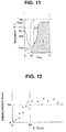
- Fig. 12 illustrates a relation between the heating amount Q and the bonding strength of the treated living tissue LT. From Fig. 12 , it is clear that an excellent treatment result can be obtained by setting the heating amount Q as a standard. That is, when the heating amount Q is equal to or larger than a predetermined heating amount QA, practically, sufficient bonding strength SA can be obtained. For the heating amount QA, an experiment is conducted beforehand, and an obtained experimental value is stored in the storage section 32M.
- Tissue temperature setting value Tset 220°C Heating amount setting value Qset: 800°C second Lower limit temperature Tmin: 50°C Upper limit temperature Tmax: 230°C
- the lower limit temperature Tmin is the temperature at which the living tissue starts to change. In other words, the living tissue is not practically treated until the lower limit temperature Tmin.
- the heating amount setting value Qset which is the time integrated value until the end of the application of the thermal energy of the tissue temperature T2 is set.
- the operator can set the treatment condition according to the treatment from the plurality of treatment conditions stored in the storage section 32M for example, however, as described later, the setting section 32 may automatically set it according to the kind of the living tissue LT.
- the respective conditions may be individually set, or may be selected as a treatment condition set in which the plurality of conditions are set beforehand.
- a plurality of treatment condition sets LV1-LV3 may be stored in the storage section 32M beforehand according to the kind of the living tissue LT to be treated, as follows.
- step S12-step S17 illustrated in Fig. 8 Since they are almost the same as step S12-step S17 illustrated in Fig. 8 , the description is omitted.
- the control section 34 determines whether or not the tissue temperature T2 has risen to the lower limit temperature Tmin or higher. When it becomes the lower limit temperature Tmin or higher (YES), the process shifts to step S16. That is, the heating amount Q is not calculated while it is below the lower limit temperature Tmin (from the time 0 to t0).
- the calculating section 33 calculates the heating amount Q which is the time integrated value of the tissue temperature T2.
- the control section 34 controls the TH power source 30, and ends the output of TH. That is, based on the heating amount setting value Qset and the heating amount Q, the output of TH is ended. Note that the control section 34 may control the TH power source 30 such that the output of TH decreases to a level at which there is practically no influence on the living tissue.
- a ratio Q/Qset of the heating amount Q calculated by the calculating section 33 to the heating amount setting value Qset is displayed at a notifying section 36B of the display section 36.
- a state of treatment progress is displayed by a bar graph at the notifying section 36B. The operator can confirm a situation of the treatment progress by display at the notifying section 36B.
- notification of the ratio Q/Qset to the operator is not limited to the notifying section 36B of the display section 36 as long as it can be recognized by the operator, and the notifying section may perform notification by sound (sound information, a kind of a melody, a change of a frequency) or vibration strength or the like.
- a treatment system 1F and the like of the fourth embodiment are described. Since the treatment system 1F and the like are similar to the treatment system 1 or 1D and the like, the same signs are attached to the components of the same function and the description is omitted.
- a treatment instrument 2F of the treatment system 1F applies the high frequency power energy (HF energy) and the thermal energy (TH energy) to the living tissue LT in order through the treatment surfaces 11SA and 11SB.
- HF energy high frequency power energy
- TH energy thermal energy
- the HF energy has a function of releasing intracellular components including polymer compounds typified by protein by destroying cell membranes of the living tissue, and integrating the intracellular components with extracellular components typified by collagen. Also, the HF energy has a function of causing the temperature of the living tissue to rise. Then, by integration and temperature rise of the living tissue, dehydration treatment and bonding of the living tissue by the application of the thermal energy performed thereafter are accelerated.
- a heat transfer body composed of a metal of the treatment instrument 2F of the treatment system 1F also has a function as an electrode 12.
- a body section 3F which is the treatment instrument control apparatus includes a high frequency power (HF) source 30A which is a first power source, a heat generation power (TH) source 30B as a second power source, an HF sensor 31A, a TH sensor 31B, the setting section 32, the calculating section 33, and the control section 34.
- HF high frequency power
- TH heat generation power
- the HF power source 30A outputs the high frequency power (HF) which is first power.
- the TH power source 30B outputs the heat generation power (TH) which is second power. Note that, since the HF power source 30A and the TH power source 30B do not simultaneously output the power, they may be one shared power source. In this case, the HF sensor 31A and the TH sensor 31B may be also shared.
- the HF sensor 31A which is a first detecting section detects the output value (voltage and current) of HF.
- the TH sensor 31B which is a second detecting section detects the output value (voltage and current) of TH.
- the treatment conditions as follows are set through the setting section 32 including the setting operation section 35.
- HF output setting value Pset 60 W HF end impedance
- Zset 120 ⁇
- Element temperature setting value Tset 180°C
- Heating amount setting value Qset 1000°C second
- the element temperature setting value Tset is set to exceed 70°C, to exceed 100°C for example, which is higher than the tissue temperature (100°C ⁇ 30°C) at the end of the HF application.
- the lower limit temperature Tmin and the upper limit temperature Tmax are also set, and the control section 34 performs the control based on the lower limit temperature Tmin and the upper limit temperature Tmax.
- the control is the same as that in the treatment system 1D and the like, the description is omitted.
- the setting section 32 may automatically set the heating amount setting value Qset according to characteristics of the living tissue LT clamped by the pair of clamping sections 11.
- the heating amount setting value Qset is automatically set based on at least one of an interval G of the pair of clamping sections 11A and 11B by which the living tissue LT is clamped and initial impedance of HF.
- the interval G is information on a size of the living tissue LT which is a body to be treated.
- the initial impedance of HF is tissue information including a moisture content of the living tissue LT. Also, as the initial impedance of HF, an impedance minimum value, or a time period during which impedance is equal to or smaller than a predetermined value, or the like can be used.
- the treatment conditions for a series of treatment are set by the setting section 32, and when treatment A is ended for example, the setting section 32 may automatically set the treatment condition for treatment B.
- the operative method is "lung lobectomy"
- when (treatment A) lobar arteria sealing, (treatment B) lobar vein sealing, (treatment C) lobar bronchial sealing, and (treatment D) interlobar solid organ sealing are to be continuously performed in order, since the treatment conditions for a series of (treatment A)-(treatment D) are set just by the operator selecting the operative method, the operability is excellent.
- the living tissue LT which is the treatment target is clamped in the pressurized state between the treatment surface 11SA of the first clamping section 11A and the treatment surface 11SB of the second clamping section 11B.
- the control section 34 starts the treatment. That is, the control section 34 first performs the control such that the HF power source 30A outputs the high frequency power (HF). HF is transmitted through the cable 2L to the electrodes 12A and 12B of the treatment instrument 2. Then, the high frequency power is applied to the living tissue LT clamped by the electrodes 12A and 12B, and the living tissue LT is heated by Joule heat.
- HF high frequency power
- the HF energy makes the living tissue itself present in an energizing route of HF between the electrode 12A and the electrode 12B generate heat. Therefore, in an HF energy applying process, even when the living tissue LT is thick, the tissue temperature T2 rises without generating temperature irregularities to a center portion. Note that, even though the treatment section 10 does not generate heat, the element temperature T1 also rises by heat transfer from the living tissue LT which generates heat.
- the control section 34 performs constant power control to an output value P1 of HF by the HF output setting value Pset, 60 W for example, based on the current and the voltage of HF detected by the HF sensor 31A.
- the calculating section 33 measures the tissue temperature T2 by a temperature sensor 19 inserted to the living tissue LT, or an infrared ray sensor or the like, and calculates the high frequency power energy heating amount (first heating amount) Q1 which is the time integrated value (integrated value) of the tissue temperature T2.
- the tissue temperature T2 when the HF energy is applied can be considered as being fixed since the living tissue LT contains water, after drastically increasing in an initial period. That is, even when the energy is applied, the temperature of the living tissue LT containing water is held at the temperature near a boiling point (100°C) which is a fixed temperature under atmospheric pressure for example, at 100°C ⁇ 30°C for example.
- a boiling point 100°C
- the first heating amount Q1 after the treatment is started until the time t may be calculated by a following (Expression 5) without using a sensor or the like.
- the first heating amount Q1 may be calculated (step S34) by the calculating section 33 using a following (Equation 6), after step S36 described later.
- Q 1 100 °C ⁇ t 1 Provided that t1; HF energy application time
- the tissue temperature T2 may be considered as a predetermined fixed temperature (100°C) and the first heating amount Q1 which is the time integrated value may be calculated.
- impedance Z is calculated by the calculating section 33 from the voltage and the current of HF detected by the HF sensor 31 A.
- the impedance Z rises.
- the control section 34 performs the treatment from S33 until the impedance Z becomes equal to or greater than the set HF end impedance Zset (No).
- the control section 34 starts the control of applying the TH energy instead of the HF energy to the living tissue LT.
- the control section 34 performs the constant temperature control on an output value P2 of the TH power source 30B based on the element temperature T1 of the treatment section 10.
- the heating element 13 is controlled so as to be the element temperature setting value Tset set in S31.
- TH may be a direct current or a high frequency, and a frequency in the case of the high frequency may be the same as HF.
- control section 34 may perform the constant temperature control to the output value P2 of the TH power source 30B based on the tissue temperature T2, similarly to the processing system 1 and the like.
- the heat generation power (TH) directly transfers the thermal energy to the living tissue LT.
- the thermal (TH) energy transferred to the living tissue LT through the treatment surfaces 11S can heat the tissue temperature T2 to the temperature exceeding 100°C, regardless of a degeneration state, the moisture content for example, of the living tissue LT, according to the element temperature setting value Tset.
- the calculating section 33 calculates the second heating amount (thermal energy heating amount) Q2 which is the time integrated value of the tissue temperature T2. That is, in S38, the element temperature measuring section 39 (not shown in the figure) calculates the element temperature T1 from the electric resistance R, performs the constant temperature control to TH based on the element temperature T1, and applies the thermal energy to the living tissue LT. Then, the first calculating section 33A estimates the temperature difference ⁇ T using a second table or a second equation stored in the storage section 38 (not shown in the figure), based on the output value of the power source 30B.
- the second table and the second equation are the table or the equation acquired beforehand based on an experiment, for estimating a temperature difference ⁇ T2 between a temperature T1B of the heating element to which the TH power is applied and the temperature (tissue temperature) T2 of the living tissue to which the TH energy is applied, based on the output value P2 of the TH power source.
- the control section 34 stops the treatment in the case that the tissue temperature T2 exceeds the upper limit temperature Tmax.
- the calculating section 33 calculates the second heating amount Q2 which is the time integrated value of the tissue temperature T2. Further, the calculating section 33 calculates the total heating amount QT for which the first heating amount Q1 and the second heating amount Q2 are added.
- the control section 34 may end the output of TH when a heating residual amount ⁇ Q indicated by a following (Equation 7) becomes zero.
- Heating residual amount ⁇ Q heating amount setting value Qset ⁇ first heating amount Q 1 ⁇ second heating amount Q 2
- control section 34 may calculate the total heating amount QT or the heating residual amount ⁇ Q. Also, the heating amount Q may be calculated only in a TH applying process without calculating the heating amount Q in an HF applying process.
- the application time period of the energy that is, energy application end
- the heating amount Q of the living tissue temperature T2 an excellent treatment result can be easily obtained. Therefore, the operability is excellent in the treatment system 1F and the like.
- first energy applied first is the high frequency power energy and second energy applied next is the thermal energy is described.
- first energy is the energy which is one of the high frequency power energy
- the thermal energy, the light energy and the ultrasound energy and the second energy is any one kind of the energy different from the first energy, similar effects can be obtained.
- a treatment system in which a treatment instrument applies two or more kinds of the treatment energy selected from the thermal energy, the ultrasound energy, the light energy and the high frequency power energy in order to the living tissue and a control section reduces or ends the output of at least one kind of the treatment energy based on the heating amount has the effects similar to that of the treatment system 1E.
- the present invention is not limited to the above-described embodiments and the like, and various changes and alterations and the like can be made within a range that does not depart from gist of the present invention.
Landscapes
- Health & Medical Sciences (AREA)
- Surgery (AREA)
- Engineering & Computer Science (AREA)
- Life Sciences & Earth Sciences (AREA)
- Biomedical Technology (AREA)
- Molecular Biology (AREA)
- Nuclear Medicine, Radiotherapy & Molecular Imaging (AREA)
- Plasma & Fusion (AREA)
- Physics & Mathematics (AREA)
- Heart & Thoracic Surgery (AREA)
- Medical Informatics (AREA)
- Otolaryngology (AREA)
- Animal Behavior & Ethology (AREA)
- General Health & Medical Sciences (AREA)
- Public Health (AREA)
- Veterinary Medicine (AREA)
- Surgical Instruments (AREA)
- Radiation-Therapy Devices (AREA)
Abstract
Description
- An embodiment of the present invention relates to a treatment system including a treatment section which applies treatment energy to biological tissue, a treatment instrument control apparatus of the treatment system, and an operation method of the treatment system.
-
U.S. Patent Application Publication No. 2009/076506 discloses a treatment system including a pair of clamping sections that apply high frequency power energy and thermal energy to a clamped body to be treated, a high frequency power source that outputs high frequency power for applying the high frequency power energy, a power source for heat generation that outputs heat generation power for applying the thermal energy, and a control section configured to control the high frequency power source and the power source for the heat generation in order to switch high frequency power energy application and application of the thermal energy. - Also,
U.S. Patent Application Publication No. 2009/0248002 discloses a treatment system that applies high frequency power energy to a body to be treated, and applies thermal energy after the application of the high frequency power energy is ended. The high frequency power energy has a function of, by destroying cell membranes of the body to be treated, releasing intracellular components including polymer compounds typified by proteins and integrating the intracellular components with extracellular components typified by collagen. Then, the body to be treated is bonded by the application of the thermal energy. -
U.S. Patent Application Publication No. 2013/19060 discloses a treatment system that applies ultrasound energy and high frequency power energy to a body to be treated. -
U.S. Patent Application Publication No. 2005/222556 discloses a treatment system that applies light energy to a body to be treated using a laser. - That is, a treatment section of a medical treatment instrument applies at least one of thermal energy, ultrasound energy, light energy and high frequency power energy to a body to be treated, as treatment energy.
- Here, in order for a treatment system to obtain an excellent treatment result, it is preferable to control an energy amount based on a temperature of living tissue that is being treated. However, it is not easy to detect a living tissue temperature during treatment. Therefore, in a conventional treatment system, control is performed based on a temperature of an energy output section, a heating element for example, which is easy to detect, instead of the living tissue temperature.
- Since control is performed based on a temperature of an energy output section that is easy to detect in a conventional treatment system, it is sometimes not easy to perform appropriate treatment.
-
- Patent Literature 1:
U.S. Patent Application Publication No. 2009/076506 - Patent Literature 2:
U.S. Patent Application Publication No. 2009/0248002 - Patent Literature 3:
U.S. Patent Application Publication No. 2013/19060 - Patent Literature 4:
U.S. Patent Application Publication No. 2005/222556 - It is an object of embodiments of the present invention to provide a treatment system with which appropriate treatment is easily performed, a treatment instrument control apparatus with which appropriate treatment is easily performed, and an operation method of the treatment system with which appropriate treatment is easily performed.
- A treatment system of an embodiment includes: a treatment instrument having an output section which applies treatment energy to living tissue; a temperature measuring section configured to measure a temperature of the output section; a power source configured to generate power for the treatment energy; a first calculating section configured to estimate a temperature difference between the temperature of the output section to which the power is applied and a temperature of the living tissue to which the treatment energy is applied, using a table or an equation stored beforehand in order to estimate the temperature difference based on an output value of the power source; a second calculating section configured to estimate the temperature of the living tissue from the temperature of the output section measured by the temperature measuring section and the temperature difference estimated by the first calculating section; and a control section configured to control the power source based on the living tissue temperature estimated by the second calculating section.
- A treatment instrument control apparatus of a different embodiment is a treatment instrument control apparatus configured to control a treatment instrument having an output section which applies treatment energy to living tissue, and includes: a power source configured to generate power for the treatment energy; a temperature measuring section configured to measure a temperature of the output section; a first calculating section configured to estimate a temperature difference between the temperature of the output section to which the power is applied and a temperature of the living tissue to which the treatment energy is applied, using a table or an equation stored beforehand in order to estimate the temperature difference based on an output value of the power source; a second calculating section configured to estimate the temperature of the living tissue from the temperature of the output section measured by the temperature measuring section and the temperature difference estimated by the first calculating section; and a control section configured to control the power source which generates the power for the treatment energy, based on the living tissue temperature estimated by the second calculating section.
- An operation method of a treatment system of a different embodiment includes: a step in which an output section of a treatment instrument starts generation of treatment energy to treat living tissue by a power source starting generation of power; a step in which a temperature measuring section measures a temperature of the output section; a step in which a first calculating section estimates a temperature difference between the temperature of the output section to which the power is applied and a temperature of the living tissue to which the treatment energy is applied, using a table or an equation stored beforehand in order to estimate the temperature difference based on an output value of the power source; a step in which a second calculating section estimates the temperature of the living tissue from the temperature of the output section measured by the temperature measuring section and the temperature difference estimated by the first calculating section; and a step in which a control section controls the power source based on the temperature of the living tissue estimated by the second calculating section.
- According to embodiments of the present invention, a treatment system with which appropriate treatment is easily performed, a treatment instrument control apparatus with which appropriate treatment is easily performed, and an operation method of the treatment system with which appropriate treatment is easily performed can be provided.
-
-
Fig. 1 is an external view of a treatment system of a first embodiment; -
Fig. 2A is a side view of a treatment section of the treatment system of the first embodiment; -
Fig. 2B is a side view of the treatment section of the treatment system of the first embodiment; -
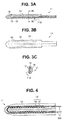
Fig. 3A is a sectional view of the treatment section of the treatment system of the first embodiment; -
Fig. 3B is a top view of the treatment section of the treatment system of the first embodiment; -
Fig. 3C is a sectional view along a 3C-3C line inFig. 3A of the treatment section of the treatment system of the first embodiment; -
Fig. 4 is a top view of a heat generating section of the treatment system of the first embodiment; -
Fig. 5 is a block diagram of the treatment system of the first embodiment; -
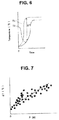
Fig. 6 is a graph for describing a change of a tissue temperature and a change of an element temperature in the treatment system of the first embodiment; -
Fig. 7 is a graph illustrating a relation between a temperature difference between the tissue temperature and the element temperature and an output value of power, in the treatment system of the first embodiment; -
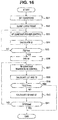
Fig. 8 is a flowchart for describing an operation method of the treatment system of the first embodiment; -
Fig. 9 is a graph illustrating a temporal change of an output value of heat generation power and a treatment section temperature, in a treatment system of a second embodiment; -
Fig. 10 is a graph illustrating a relation between a temperature difference between a living tissue temperature and the treatment section temperature and the output value of the heat generation power, in the treatment system of the second embodiment; -
Fig. 11 is a graph for describing a heating amount, in a treatment system of a third embodiment; -
Fig. 12 is a graph illustrating a relation between the heating amount and living tissue bonding strength in the treatment system of the third embodiment; -
Fig. 13 is a flowchart for describing an operation method of the treatment system of the third embodiment; -
Fig. 14 is a block diagram of a treatment system of a fourth embodiment; -
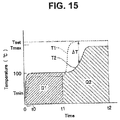
Fig. 15 is a graph for describing a temperature change of living tissue and a treatment section, and a heating amount in the treatment system of the fourth embodiment; and -
Fig. 16 is a flowchart for describing the operation method of the treatment system of the fourth embodiment. - As illustrated in
Fig. 1 , atreatment system 1 of the present embodiment includes atreatment instrument 2, abody section 3 which is a treatment instrument control apparatus, and afoot switch 4. Thetreatment instrument 2 is a surgical energy anastomosis device that performs joining treatment or the like of living tissue inside an abdominal cavity through an abdominal wall for example. - The
treatment instrument 2 includes a grip 2A1, a shaft 2A2, and atreatment section 10 composed of an openable and closable pair of clamping sections 11 (afirst clamping section 11A and asecond clamping section 11B) that holds and treats living tissue LT, which is a body to be treated. - Note that, hereinafter, when respective components of the same function for which A and B are imparted to ends of signs are expressed, the signs A and B are sometimes omitted. For example, the
first clamping section 11A and thesecond clamping section 11B are respectively called theclamping sections 11. - The grip 2A1 is connected to the
body section 3 through acable 2L. The grip 2A1 with an opening/closing knob 2A3 with which an operator operates opening and closing of thetreatment section 10 has a shape that the operator easily holds, a roughly L shape for example. At one end of the grip 2A1, the shaft 2A2 that is integrated with thetreatment section 10 and transmits an operation of the opening/closing knob 2A3 to thetreatment section 10 is disposed. On the other hand, the other end side of the grip 2A1 is a grasping section 2A4 to be grasped by the operator. - The
body section 3 has adisplay section 36 that displays a treatment condition or the like and asetting operation section 35 with which the operator sets the treatment condition or the like on a front surface panel, and thefoot switch 4 is connected through acable 4L. By the operator pressurizing a pedal of thefoot switch 4 with a foot, power output from thebody section 3 to thetreatment instrument 2 is ON/OFF controlled. Thefoot switch 4 is not an essential component, and may be a switch that the operator operates at hand or the like. - As illustrated in
Fig. 2A and Fig. 2B , thetreatment instrument 2 applies thermal energy (TH energy) to the living tissue LT throughtreatment surfaces 11S (11SA, 11SB) which are contact surfaces with the living tissue LT. - The
treatment section 10 is freely openable and closable by thesecond clamping section 11B moving relative to thefirst clamping section 11A, for example. As illustrated inFig. 2A , when the opening/closing knob 2A3 is not pressurized by the operator, thesecond clamping section 11B is in a close state or a contact state with thefirst clamping section 11A by energizing force of an elastic member not shown in the figure. In contrast, as illustrated inFig. 2B , when the opening/closing knob 2A3 is pressurized by the operator with force stronger than the energizing force of the elastic member, thesecond clamping section 11B is separated from thefirst clamping section 11A and thetreatment section 10 is turned to an open state. The living tissue LT inserted between thefirst clamping section 11A and thesecond clamping section 11 B when thetreatment section 10 is in the open state is, when the operator stops a pressurizing operation of the opening/closing knob 2A3, held in a state of being held and pressurized between the treatment surface 11SA of thefirst clamping section 11A and the treatment surface 11SB of thesecond clamping section 11B by the energizing force of the elastic member. - As illustrated in
Fig. 3A-Fig. 4 , thetreatment surface 11S of the clampingsections 11 is a front surface (outer surface) of aheat transfer body 12 composed of a metal such as stainless steel or copper. Then, to a back surface (inner surface) of theheat transfer body 12, aheating element 13 is bonded. An upper surface of theheating element 13 is covered with aninsulator 16 such as polyimide, and insulated. - For the
heating element 13, aheating resistor 15 is formed on a surface of asubstrate 14 of alumina, aluminum nitride, or the like. Theheating resistor 15 is composed of platinum of a positive temperature coefficient of resistance whose electric resistance R becomes high when a temperature rises. Therefore, as described later, an elementtemperature measuring section 39 can calculate a temperature T1 of the heating element 13 (heating resistor 15) from the electric resistance R of theheating resistor 15. For a material of theheating resistor 15, various kinds of high melting point metal materials of the positive temperature coefficient of resistance such as a NiCr alloy, Ta or W may be also used. - The
heating element 13 is an output section that applies heat generation power (TH) outputted from thebody section 3 to the living tissue LT as the thermal energy. - The
heating element 13 is disposed to therespective clamping sections heating element 13 may be disposed to at least oneclamping section 11. - Next, a configuration of the
treatment system 1 is described usingFig. 5 . As already described, thetreatment system 1 includes thetreatment instrument 2, thebody section 3 and thefoot switch 4. - The
body section 3 is provided with a heat generation power (TH)source 30, a heat generation power sensor (TH sensor) 31, asetting section 32, a calculatingsection 33, acontrol section 34, astorage section 38, and the elementtemperature measuring section 39. - The
power source 30 outputs the heat generation power (TH) for the thermal energy. TheTH sensor 31 which is a detecting section detects an output value (voltage and current) of TH. A product of the voltage and the current is power P. - The
control section 34 controls theentire treatment system 1. - The element
temperature measuring section 39 which is a temperature measuring section configured to measure a temperature of the output section indirectly measures an element temperature T1 by calculating the electric resistance R of theheating element 13 from the voltage and the current of TH and calculating the temperature (element temperature) T1 of theheating element 13 which is the output section from the calculated electric resistance R. That is, the elementtemperature measuring section 39 has a storage section (not shown in the figure) storing a calculating equation based on the temperature coefficient of resistance of theheating element 13 or a correspondence table of the electric resistance R and the element temperature T1 or the like. Note that the elementtemperature measuring section 39 may not calculate the electric resistance R from the voltage and the current of TH and may directly calculate the element temperature T1. Also, the elementtemperature measuring section 39 may directly measure the element temperature T1 by a temperature sensor such as a thermocouple disposed near theheating element 13. - As illustrated in
Fig. 6 , there is a temperature difference ΔT between the element temperature T1 and a temperature (tissue temperature) T2 of the living tissue. Then, the temperature difference ΔT changes with a lapse of a treatment time period. Therefore, there is a case that it is not easy to perform appropriate treatment by control based on theelement temperature T 1. - An inventor has found, as a result of intensive studies, that the temperature difference ΔT is strongly correlated with an output value P of the heat generation power (TH), as illustrated in
Fig. 7 . This is because that, since the output value P is subjected to constant temperature control such that the element temperature T1 becomes a predetermined element temperature setting value Tset, when the temperature difference ΔT is large, TH of a larger output value P is needed. - Then, in the
treatment system 1, in thestorage section 38, a table (table data) or an equation for estimating the temperature difference ΔT between the element temperature T1 and the temperature T2 of the living tissue based on the output value of thepower source 30 is stored. - Therefore, T2 can be calculated from a following (Equation 1).

- Note that
Fig. 7 illustrates a straight line for which a plurality of pieces of experimental data (plots) based on ΔT obtained by actually measuring the temperature of the living tissue using a temperature sensor are subjected to linear expression approximation by a least-squares method. - That is, an equation f(P) of a straight line illustrated in
Fig. 6 is ΔT=αP+β (α: inclination, β: Y-intercept). The equation f(P) may be a quadratic equation or the like, or the power P may be sectioned into a plurality of ranges and the equation f(P) may be configured from a plurality of different equations for respective sections. Also, in the case of storing the table, ΔT corresponding to 5W each of the power P for example is stored in the table. - Depending on kinds of the living tissue or the like, the different equation f(P) may be stored. Note that the tissue temperature T2 is not limited to an internal temperature of the living tissue, and may be a temperature of a surface in contact with the
treatment surface 11 S. - The calculating
section 33 calculates the temperature T2 of the living tissue that is being treated. Hereinafter, for convenience of description, the calculatingsection 33 is separated into afirst calculating section 33A and asecond calculating section 33B by the functions and described. - The
first calculating section 33A estimates the temperature difference ΔT using the stored table or equation stored beforehand based on the output value P of thepower source 30. - The
second calculating section 33B estimates the tissue temperature T2 using the (Equation 1) from the element temperature T1 measured by the elementtemperature measuring section 39 and the temperature difference ΔT estimated by the first calculatingsection 33A. - The
setting section 32 sets the treatment condition based on an operation of thesetting operation section 35 or the like. In thetreatment system 1, thesetting section 32 includes astorage section 32M. Thestorage section 32M composed of a semiconductor memory or the like may store the plurality of treatment conditions according to the kinds of the living tissue, for example. Note that thesetting operation section 35 can be considered as a part of asetting section 32S in a broad sense. - A CPU or the like configuring the
control section 34 may include at least some of functions of the elementtemperature measuring section 39, the calculatingsection 33 and thesetting section 32. Also, the respective sections may be independent CPUs. Also, thestorage section 38 composed of the semiconductor memory or the like may include the functions of thestorage section 32M of the setting section and the storage section of the calculatingsection 33. Conversely, the calculatingsection 33 may include the semiconductor memory or the like having the function of thestorage section 38. - The
display section 36 is a notifying section that notifies the operator of information or the like such as the set treatment conditions, the output value of the power during treatment, and the tissue temperature T2. - In the
treatment system 1, thecontrol section 34 controls thepower source 30 based on the tissue temperature T2 estimated by thesecond calculating section 33B. - Next, along a flowchart in
Fig. 8 , an operation method of thetreatment system 1 is described. - For example, the treatment conditions as follows are set through the
setting section 32 including thesetting operation section 35.
Tissue temperature setting value Tset: 190°C
Upper limit temperature Tmax: 200°C
Treatment time period t: 10 seconds - Here, the tissue temperature setting value Tset is a target temperature for which the
control section 34 performs constant temperature control. The upper limit temperature Tmax is a temperature at which a risk that the living tissue that is being treated is unexpectedly damaged and a peripheral portion is adversely affected starts to arise. - As already described, while the element temperature T1 is set as a target temperature for which the constant temperature control is performed in a conventional treatment system, in the
treatment system 1, the tissue temperature T2 is set. - As illustrated in
Fig. 2A , thetreatment section 10 in the closed state is inserted into an abdominal cavity through an abdominal wall, for example. When the operator performs a pressurizing operation of grasping the opening/closing knob 2A3 of the grip 2A1, thesecond clamping section 11B opens from thefirst clamping section 11A. Then, the living tissue LT which is a treatment target is arranged between the treatment surface 11SA of thefirst clamping section 11A and the treatment surface 11SB of thesecond clamping section 11B. In the state, when the opening/closing knob 2A3 is opened, by the energizing force of the elastic member, thesecond clamping section 11B is closed to thefirst clamping section 11A, and as illustrated inFig. 2B , the living tissue LT which is the treatment target is clamped in a pressurized state between the treatment surface 11SA of thefirst clamping section 11 A and the treatment surface 11SB of thesecond clamping section 11B. - The operator pressurizes the
foot switch 4 with a foot. Then, thecontrol section 34 performs control such that theTH power source 30 outputs the heat generation power (TH). - The element
temperature measuring section 39 calculates the electric resistance R of theheating element 13 from the output value P (voltage and current) of the heat generation power, and calculates the temperature (element temperature) T1 of the heating element from the calculated electric resistance R. - In the
treatment system 1, an average temperature of theheating elements heating elements - The
first calculating section 33A estimates the temperature difference ΔT using the table or the equation stored beforehand based on the output value P. - The
second calculating section 33B estimates the tissue temperature T2 using the (Equation 1) from the element temperature T1 measured by the elementtemperature measuring section 39 and the temperature difference ΔT estimated by the first calculatingsection 33A. - The
control section 34 stops the treatment in the case that the tissue temperature T2 exceeds the upper limit temperature Tmax. At the time, it is preferable that thecontrol section 34 displays an alarm at thedisplay section 36. - The
control section 34 stops the treatment when pressurization of thefoot switch 4 becomes absent (SW OFF: Yes). Until then, the treatment from step S13 is repeatedly performed. - In the
treatment system 1, the body section 3 (treatment instrument control apparatus) and theoperation method 1 of the treatment system, the control is performed based on the temperature T2 of the living tissue that is being actually treated. Therefore, the tissue temperature T2 does not exceed the upper limit temperature Tmax. Also, more appropriate treatment can be performed compared to a conventional processing system or the like in which the control is performed by the element temperature or the like. - Next,
treatment systems 1A-1C, the treatment instrument control apparatus, and the operation method of the treatment system of modifications 1-3 of the first embodiment are described. Note that, hereinafter, "the treatment system, the treatment instrument control apparatus, and the operation method of thetreatment system 1" are called the treatment system and the like. Since thetreatment systems 1A-1C and the like are similar to thetreatment system 1 and the like, same signs are attached to components of the same function and the description is omitted. - In the
treatment system 1, the treatment energy to be applied is the thermal energy. However, as long as the treatment energy is the energy which is one of the thermal energy, ultrasound energy, light energy and high frequency power energy, similar effects can be obtained. - In the
treatment system 1A and the like of themodification 1, a laser beam which is the light energy is applied to the living tissue as the treatment energy. That is, the power source outputs the power to a light source which generates the laser beam. - The living tissue to which the laser beam is applied generates heat. By selecting a wavelength of the laser beam, a specific treatment portion may be selectively heated.
- In the treatment system 1B and the like of the
modification 2, the ultrasound energy is applied to the living tissue as the treatment energy. That is, the power source outputs the power to an ultrasound transducer. - The treatment instrument of the treatment system 1B includes an ultrasound transducer inside the grip 2A1, and the
clamping section 11A vibrates to produce ultrasound. The living tissue clamped with the fixedclamping section 11B generates heat by frictional heat. - In the treatment system 1C and the like of the
modification 3, the high frequency power energy is applied to the living tissue as the treatment energy. That is, the power source outputs high frequency power. - A heat transfer body composed of a metal of the treatment instrument of the treatment system 1C has a function as an electrode that applies the high frequency power (HF) to the living tissue. When the high frequency power is applied to the living tissue LT clamped by
electrodes - In all of the
treatment systems 1A-1C, the treatment instrument control apparatus, and the operation method of the treatment system of the modifications of the first embodiment, similarly to thetreatment system 1 and the like, the temperature T1 of the output section and the output value P of the power source are measured, the temperature difference ΔT is estimated from the temperature T1 and the output value P, and the tissue temperature T2 is estimated from the temperature difference ΔT. - Then, in the case that the tissue temperature T2 exceeds the upper limit temperature Tmax, the treatment is stopped.
- That is, the
control section 34 controls thepower source 30 such that the tissue temperature T2 estimated by thesecond calculating section 33B does not exceed the upper limit temperature Tmax. Therefore, in all of thetreatment systems 1A-1C and the like of the modifications, it is easy to perform the appropriate treatment. - Next, a treatment system 1D and the like of the second embodiment are described. Since the treatment system 1D and the like are similar to the
treatment system 1 and the like, the same signs are attached to the components of the same function and the description is omitted. - In the treatment system 1D, for example, the
storage section 38 of a treatment instrument control apparatus 3D stores a table or an expression for estimating the temperature difference ΔT based not only on the output value P of thepower source 30 but also on the output value P and the temperature T1 of the output section (heating element 13), and the first calculatingsection 33A estimates the temperature difference ΔT based on the output value P of the power and the temperature T1 of the output section. - That is, in the treatment system 1D, the first calculating
section 33A calculates the temperature difference ΔT from the element temperature T1 of theheating element 13 and the output value P of the heat generation power (TH), in step S 15 illustrated inFig. 8 . - As already described, the temperature difference ΔT between the tissue temperature T2 and the element temperature T1 is strongly correlated with the output value P of the heat generation power (TH). Then, by considering not only the output value P but also the element temperature T1, the temperature difference ΔT can be more accurately estimated.

- As illustrated in
Fig. 9 , immediately after heating processing is started (in an initial period L1), because of a heat capacity or the like of theheating element 13 itself, the element temperature T1 rises extremely slowly so that it can be considered as being roughly fixed. In contrast, while the temperature of theheating element 13 is rising (in a temperature rising period L2), the element temperature T1 is in a state of being greatly lower than the temperature setting value Tset. Therefore, the output value P suddenly increases. Then, when the element temperature T1 approaches the temperature setting value Tset (in a temperature rising completing period L3), the output value P starts to decrease in order to prevent overshoot. Then, when a stable state is attained, the output value P further decreases and becomes a roughly fixed value (a stable period L4). - In
Fig. 10 , a relation between the output value P and the temperature difference ΔT is plotted separately in the four periods described above. That is, data of the period L1 is plotted with black triangle marks, data of the period L2 is plotted with black round marks, data of the period L3 is plotted with white round marks, and data of the period L4 is plotted with white triangle marks, respectively. - As is clear from
Fig. 10 , in the case of calculating the temperature difference ΔT from the output value P, by changing the calculating equation according to the four periods, calculation with higher accuracy is possible. Here, the first calculatingsection 33A determines the four periods L1-L4 from the element temperature T1 or the output value P. - That is, the time period immediately after the rising of the element temperature T1 is started is the period L1, the time period during the rising is the period L2, the time period during which the element temperature T1 approaches the element temperature setting value Tset, the output value P decreases and a decrease speed becomes equal to or lower than a predetermined value is the period L3, and the time period thereafter is the period L4.
- The calculating equations in the respective periods can be appropriately set. For example, ΔT may be considered as being fixed in the
period 1, and linear expression approximation may be performed in the periods L2-L4. Also, separation may be performed into five or more periods, or separation may be performed into three or fewer periods. - In the treatment system 1D and the like, since the temperature difference ΔT which is more highly accurate than that of a
processing system 1 and the like can be estimated, more appropriate treatment can be performed. - Note that the temperature difference ΔT is sometimes affected by pressurizing power PP between the
treatment surface 11 SA of thefirst clamping section 11 A and the treatment surface 11SB of thesecond clamping section 11B. Therefore, by disposing a pressure sensor to the treatment surfaces 11 S and using the pressurizing power PP also in estimation of the temperature difference ΔT, the more highly accurate temperature difference ΔT can be estimated. Note that the temperature difference ΔT is fixed with the pressurizing power PP equal to or greater than a predetermined pressure. Therefore, thecontrol section 34 may control thepower source 30 such that the treatment is not started in the case that the pressurizing power PP is below the predetermined pressure. - Next, a
treatment system 1E and the like of the third embodiment are described. Since thetreatment system 1E and the like are similar to thetreatment system 1 and the like, the same signs are attached to the components of the same function and the description is omitted. - In the
treatment system 1E, the calculatingsection 33 of a treatmentinstrument control apparatus 3E calculates a heating amount Q which is a time integrated value of the tissue temperature T2, and thecontrol section 34 controls thepower source 30 so as to reduce or end the output of the power when the heating amount Q becomes equal to or larger than a predetermined heating amount setting value Qset. That is, while processing completion is controlled based on a preset treatment time period for example in thetreatment system 1 and the like, the control is performed based on the heating amount Q in thetreatment system 1E. - In order to obtain an excellent treatment result, it is needed to appropriately set an application time period of the treatment energy. Bonding strength is insufficient when the application time period is short, and surrounding tissue is adversely affected or the bonding strength becomes insufficient when the application time period is long.
- The heating amount Q is the time integrated value of the temperature, that is, a product of the temperature and the application time period, and is indicated in units of "°C second" for example. For example, by a following (Equation 3), the heating amount Q from treatment start (time 0) to the time t1 is calculated (see
Fig. 11 ). Note that a lower limit temperature Tmin inFig. 11 is described later.
- The heating amount Q can be also expressed as an integrated value (integrated temperature) in units of "°C", for which the living tissue temperature T2 at every predetermined interval of time, every second for example, is added. That is, the time integrated value of the temperature and the integrated temperature are physical quantities that are in different units but indicate the same state. Note that the heating amount Q is the physical quantity that is completely different from calories in units of joules.
-
Fig. 12 illustrates a relation between the heating amount Q and the bonding strength of the treated living tissue LT. FromFig. 12 , it is clear that an excellent treatment result can be obtained by setting the heating amount Q as a standard. That is, when the heating amount Q is equal to or larger than a predetermined heating amount QA, practically, sufficient bonding strength SA can be obtained. For the heating amount QA, an experiment is conducted beforehand, and an obtained experimental value is stored in thestorage section 32M. - Next, along a flowchart in
Fig. 13 , the operation method of thetreatment system 1E is described. - For example, the treatment conditions as follows are set through the
setting section 32 including thesetting operation section 35.
Tissue temperature setting value Tset: 220°C
Heating amount setting value Qset: 800°C second
Lower limit temperature Tmin: 50°C
Upper limit temperature Tmax: 230°C - Here, the lower limit temperature Tmin is the temperature at which the living tissue starts to change. In other words, the living tissue is not practically treated until the lower limit temperature Tmin.
- As already described, while the treatment time period (the application time period of the treatment energy) is set as the processing condition in the conventional treatment system, in the
treatment system 1, the heating amount setting value Qset which is the time integrated value until the end of the application of the thermal energy of the tissue temperature T2 is set. - Note that the operator can set the treatment condition according to the treatment from the plurality of treatment conditions stored in the
storage section 32M for example, however, as described later, thesetting section 32 may automatically set it according to the kind of the living tissue LT. - That is, the respective conditions may be individually set, or may be selected as a treatment condition set in which the plurality of conditions are set beforehand. For example, a plurality of treatment condition sets LV1-LV3 may be stored in the
storage section 32M beforehand according to the kind of the living tissue LT to be treated, as follows. - (LV1)
Tissue temperature setting value Tset: 180°C
Heating amount setting value Qset: 1000°C second
Lower limit temperature Tmin: 50°C
Upper limit temperature Tmax: 190°C - (LV2)
Tissue temperature setting value Tset: 190°C
Heating amount setting value Qset: 2500°C second
Lower limit temperature Tmin: 50°C
Upper limit temperature Tmax: 200°C - (LV3)
Tissue temperature setting value Tset: 200°C
Heating amount setting value Qset: 3500°C second
Lower limit temperature Tmin: 50°C
Upper limit temperature Tmax: 210°C - Since they are almost the same as step S12-step S17 illustrated in
Fig. 8 , the description is omitted. - The
control section 34 determines whether or not the tissue temperature T2 has risen to the lower limit temperature Tmin or higher. When it becomes the lower limit temperature Tmin or higher (YES), the process shifts to step S16. That is, the heating amount Q is not calculated while it is below the lower limit temperature Tmin (from thetime 0 to t0). - The calculating
section 33 calculates the heating amount Q which is the time integrated value of the tissue temperature T2. - For the heating amount Q indicated by (Equation 3), at every predetermined interval of time, every second for example, AQ (tissue temperature T2×1 second) is added to the previous heating amount Q.
- Note that, even when similar control is performed based on the heating amount which is the time integrated value of the element temperature T1 of the
heating element 13, compared to conventional control based on time, an excellent treatment result can be obtained. However, in order to perform more accurate treatment, it is preferable to perform the control using the tissue temperature T2. - When the heating amount Q becomes equal to or larger than the heating amount setting value Qset (YES), the
control section 34 controls theTH power source 30, and ends the output of TH. That is, based on the heating amount setting value Qset and the heating amount Q, the output of TH is ended. Note that thecontrol section 34 may control theTH power source 30 such that the output of TH decreases to a level at which there is practically no influence on the living tissue. - In the
treatment system 1E, since the application time period of the thermal energy is controlled with the heating amount Q as the standard, an excellent treatment result can be easily obtained. That is, in the operation method of thetreatment system 1E and the like, operability is excellent. - Also, it is preferable that a ratio Q/Qset of the heating amount Q calculated by the calculating
section 33 to the heating amount setting value Qset is displayed at a notifying section 36B of thedisplay section 36. For example, a state of treatment progress is displayed by a bar graph at the notifying section 36B. The operator can confirm a situation of the treatment progress by display at the notifying section 36B. - Note that notification of the ratio Q/Qset to the operator is not limited to the notifying section 36B of the
display section 36 as long as it can be recognized by the operator, and the notifying section may perform notification by sound (sound information, a kind of a melody, a change of a frequency) or vibration strength or the like. - Next, a
treatment system 1F and the like of the fourth embodiment are described. Since thetreatment system 1F and the like are similar to thetreatment system 1 or 1D and the like, the same signs are attached to the components of the same function and the description is omitted. - A
treatment instrument 2F of thetreatment system 1F applies the high frequency power energy (HF energy) and the thermal energy (TH energy) to the living tissue LT in order through the treatment surfaces 11SA and 11SB. - The HF energy has a function of releasing intracellular components including polymer compounds typified by protein by destroying cell membranes of the living tissue, and integrating the intracellular components with extracellular components typified by collagen. Also, the HF energy has a function of causing the temperature of the living tissue to rise. Then, by integration and temperature rise of the living tissue, dehydration treatment and bonding of the living tissue by the application of the thermal energy performed thereafter are accelerated.
- As illustrated in
Fig. 14 , a heat transfer body composed of a metal of thetreatment instrument 2F of thetreatment system 1F also has a function as anelectrode 12. Then, abody section 3F which is the treatment instrument control apparatus includes a high frequency power (HF)source 30A which is a first power source, a heat generation power (TH)source 30B as a second power source, anHF sensor 31A, aTH sensor 31B, thesetting section 32, the calculatingsection 33, and thecontrol section 34. - The
HF power source 30A outputs the high frequency power (HF) which is first power. TheTH power source 30B outputs the heat generation power (TH) which is second power. Note that, since theHF power source 30A and theTH power source 30B do not simultaneously output the power, they may be one shared power source. In this case, theHF sensor 31A and theTH sensor 31B may be also shared. - The
HF sensor 31A which is a first detecting section detects the output value (voltage and current) of HF. TheTH sensor 31B which is a second detecting section detects the output value (voltage and current) of TH. - As illustrated in
Fig. 15 , in thetreatment system 1F, after the application of the HF energy is ended, the application of the TH energy is started (time t=t1). Then, thecontrol section 34 controls treatment end (time t=t2) based on the time integrated value of the tissue temperature T2 defined by the heating amount Q. - That is, when a total heating amount QT which is an added value of a high frequency power energy heating amount (first heating amount) Q1 by HF energy application and a thermal energy heating amount (second heating amount) Q2 by TH energy application becomes equal to or larger than the heating amount setting value Qset set beforehand (time t=t2), the
control section 34 performs the control such that theTH power source 30B ends the TH energy application. That is,
- Next, along a flowchart in
Fig. 16 , the operation method of thetreatment system 1F is described in detail. - For example, the treatment conditions as follows are set through the
setting section 32 including thesetting operation section 35.
HF output setting value Pset: 60 W
HF end impedance Zset: 120 Ω
Element temperature setting value Tset: 180°C
Heating amount setting value Qset: 1000°C second - Note that the element temperature setting value Tset is set to exceed 70°C, to exceed 100°C for example, which is higher than the tissue temperature (100°C±30°C) at the end of the HF application.
- Also, similarly to the treatment system 1D and the like, the lower limit temperature Tmin and the upper limit temperature Tmax are also set, and the
control section 34 performs the control based on the lower limit temperature Tmin and the upper limit temperature Tmax. However, since the control is the same as that in the treatment system 1D and the like, the description is omitted. - Note that the
setting section 32 may automatically set the heating amount setting value Qset according to characteristics of the living tissue LT clamped by the pair of clampingsections 11. - For example, the heating amount setting value Qset is automatically set based on at least one of an interval G of the pair of clamping
sections - The interval G is information on a size of the living tissue LT which is a body to be treated. The initial impedance of HF is tissue information including a moisture content of the living tissue LT. Also, as the initial impedance of HF, an impedance minimum value, or a time period during which impedance is equal to or smaller than a predetermined value, or the like can be used.
- Further, when the operator selects an operative method by the setting
operation section 35, the treatment conditions for a series of treatment are set by thesetting section 32, and when treatment A is ended for example, thesetting section 32 may automatically set the treatment condition for treatment B. For example, in the case that the operative method is "lung lobectomy", when (treatment A) lobar arteria sealing, (treatment B) lobar vein sealing, (treatment C) lobar bronchial sealing, and (treatment D) interlobar solid organ sealing are to be continuously performed in order, since the treatment conditions for a series of (treatment A)-(treatment D) are set just by the operator selecting the operative method, the operability is excellent. - The living tissue LT which is the treatment target is clamped in the pressurized state between the treatment surface 11SA of the
first clamping section 11A and the treatment surface 11SB of thesecond clamping section 11B. - In the state that the living tissue LT is clamped at the
treatment section 10, the operator pressurizes thefoot switch 4 with a foot. Then, thecontrol section 34 starts the treatment. That is, thecontrol section 34 first performs the control such that theHF power source 30A outputs the high frequency power (HF). HF is transmitted through thecable 2L to theelectrodes treatment instrument 2. Then, the high frequency power is applied to the living tissue LT clamped by theelectrodes - That is, the HF energy makes the living tissue itself present in an energizing route of HF between the
electrode 12A and theelectrode 12B generate heat. Therefore, in an HF energy applying process, even when the living tissue LT is thick, the tissue temperature T2 rises without generating temperature irregularities to a center portion. Note that, even though thetreatment section 10 does not generate heat, the element temperature T1 also rises by heat transfer from the living tissue LT which generates heat. - The
control section 34 performs constant power control to an output value P1 of HF by the HF output setting value Pset, 60 W for example, based on the current and the voltage of HF detected by theHF sensor 31A. - The calculating
section 33 measures the tissue temperature T2 by a temperature sensor 19 inserted to the living tissue LT, or an infrared ray sensor or the like, and calculates the high frequency power energy heating amount (first heating amount) Q1 which is the time integrated value (integrated value) of the tissue temperature T2. - Here, as illustrated in
Fig. 15 , the tissue temperature T2 when the HF energy is applied can be considered as being fixed since the living tissue LT contains water, after drastically increasing in an initial period. That is, even when the energy is applied, the temperature of the living tissue LT containing water is held at the temperature near a boiling point (100°C) which is a fixed temperature under atmospheric pressure for example, at 100°C±30°C for example. - Therefore, the first heating amount Q1 after the treatment is started until the time t may be calculated by a following (Expression 5) without using a sensor or the like.

- Further, the first heating amount Q1 may be calculated (step S34) by the calculating
section 33 using a following (Equation 6), after step S36 described later.
- As described above, in S34, while the constant power control is performed to HF and the HF energy is applied, the tissue temperature T2 may be considered as a predetermined fixed temperature (100°C) and the first heating amount Q1 which is the time integrated value may be calculated.
- In the
treatment system 1F, when HF energy application is started, impedance Z is calculated by the calculatingsection 33 from the voltage and the current of HF detected by theHF sensor 31 A. - By dehydration or the like accompanying degeneration of the living tissue LT accompanying progress of the treatment, the impedance Z rises. The
control section 34 performs the treatment from S33 until the impedance Z becomes equal to or greater than the set HF end impedance Zset (No). - When the impedance Z becomes equal to or greater than the set HF end impedance Zset (YES), in S26, the
control section 34 controls theHF power source 30A and ends the output of HF (t=t1). - That is, based on the impedance Z of HF, the output of HF is ended.
- The
control section 34 starts the control of applying the TH energy instead of the HF energy to the living tissue LT. - In the TH energy application, the
control section 34 performs the constant temperature control on an output value P2 of theTH power source 30B based on the element temperature T1 of thetreatment section 10. In other words, theheating element 13 is controlled so as to be the element temperature setting value Tset set in S31. TH may be a direct current or a high frequency, and a frequency in the case of the high frequency may be the same as HF. - Note that the
control section 34 may perform the constant temperature control to the output value P2 of theTH power source 30B based on the tissue temperature T2, similarly to theprocessing system 1 and the like. - While the high frequency power (HF) applied from the
electrode 12 to the living tissue LT heats the living tissue LT as Joule heat, the heat generation power (TH) directly transfers the thermal energy to the living tissue LT. The thermal (TH) energy transferred to the living tissue LT through the treatment surfaces 11S can heat the tissue temperature T2 to the temperature exceeding 100°C, regardless of a degeneration state, the moisture content for example, of the living tissue LT, according to the element temperature setting value Tset. - The calculating
section 33 calculates the second heating amount (thermal energy heating amount) Q2 which is the time integrated value of the tissue temperature T2. That is, in S38, the element temperature measuring section 39 (not shown in the figure) calculates the element temperature T1 from the electric resistance R, performs the constant temperature control to TH based on the element temperature T1, and applies the thermal energy to the living tissue LT. Then, the first calculatingsection 33A estimates the temperature difference ΔT using a second table or a second equation stored in the storage section 38 (not shown in the figure), based on the output value of thepower source 30B. The second table and the second equation are the table or the equation acquired beforehand based on an experiment, for estimating a temperature difference ΔT2 between a temperature T1B of the heating element to which the TH power is applied and the temperature (tissue temperature) T2 of the living tissue to which the TH energy is applied, based on the output value P2 of the TH power source. - The
control section 34 stops the treatment in the case that the tissue temperature T2 exceeds the upper limit temperature Tmax. - The calculating
section 33 calculates the second heating amount Q2 which is the time integrated value of the tissue temperature T2. Further, the calculatingsection 33 calculates the total heating amount QT for which the first heating amount Q1 and the second heating amount Q2 are added. - When the total heating amount QT becomes equal to or larger than the heating amount setting value Qset (YES), the
control section 34 controls theTH power source 30B and ends the output of TH (t=t2). That is, based on the heating amount setting value Qset and the total heating amount QT, the output of TH is ended. - Here, since the first heating amount Q1 is already calculated and does not increase or decrease in the process after S36, the
control section 34 may end the output of TH when a heating residual amount ΔQ indicated by a following (Equation 7) becomes zero.
- Note that the
control section 34 may calculate the total heating amount QT or the heating residual amount ΔQ. Also, the heating amount Q may be calculated only in a TH applying process without calculating the heating amount Q in an HF applying process. - In the
treatment system 1F and the like, since the application time period of the energy, that is, energy application end, is controlled using the heating amount Q of the living tissue temperature T2, an excellent treatment result can be easily obtained. Therefore, the operability is excellent in thetreatment system 1F and the like. - Note that, in the above description, a case that first energy applied first is the high frequency power energy and second energy applied next is the thermal energy is described. However, when the first energy is the energy which is one of the high frequency power energy, the thermal energy, the light energy and the ultrasound energy and the second energy is any one kind of the energy different from the first energy, similar effects can be obtained.
- That is, a treatment system in which a treatment instrument applies two or more kinds of the treatment energy selected from the thermal energy, the ultrasound energy, the light energy and the high frequency power energy in order to the living tissue and a control section reduces or ends the output of at least one kind of the treatment energy based on the heating amount has the effects similar to that of the
treatment system 1E. - For example, even a treatment system that stops bleeding of a blood vessel by the application of the HF energy and then cuts off the blood vessel by the application of the ultrasound energy has the similar effects by performing the control similar to that of the treatment system 1D.
- Also, a bipolar treatment instrument with which the living tissue LT is grasped by the pair of clamping
sections 11 is described; however, even with a monopolar treatment instrument, as long as the control is performed similarly with the total heating amount QT as a standard in the treatment system, an excellent treatment result can be easily obtained. - The present invention is not limited to the above-described embodiments and the like, and various changes and alterations and the like can be made within a range that does not depart from gist of the present invention.
- The present application is applied with application number
61/861,683 -
- 1, 1A-1F ... Treatment system
- 2 ... Treatment instrument
- 3 ... Body section (treatment instrument control apparatus)
- 13 ... Heating element
- 19 ... Temperature sensor
- 30 ... Power source
- 33 ... Calculating section
- 33A ... First calculating section
- 33B ... Second calculating section
- 34 ... Control section
- 39 ... Element temperature measuring section
Claims (15)
- A treatment system comprising:a treatment instrument having an output section which applies treatment energy to living tissue;a temperature measuring section configured to measure a temperature of the output section;a power source configured to generate power for the treatment energy;a first calculating section configured to estimate a temperature difference between the temperature of the output section to which the power is applied and a temperature of the living tissue to which the treatment energy is applied, using a table or an equation stored beforehand in order to estimate the temperature difference based on an output value of the power source;a second calculating section configured to estimate the temperature of the living tissue from the temperature of the output section measured by the temperature measuring section and the temperature difference estimated by the first calculating section; anda control section configured to control the power source based on the temperature of the living tissue estimated by the second calculating section.
- The treatment system according to claim 1, wherein the treatment energy is at least one of thermal energy, ultrasound energy, light energy, and high frequency power energy.
- The treatment system according to claim 2, wherein the control section controls the power source so that the temperature of the living tissue estimated by the second calculating section does not exceed a predetermined upper limit temperature.
- The treatment system according to claim 3,
wherein the treatment energy is the thermal energy, and
the output section is a heating element which converts the power to the thermal energy. - The treatment system according to claim 4, wherein the control section controls the power source so as to reduce or end output of the power when a heating amount which is a time integrated value of the temperature of the living tissue becomes equal to or larger than a predetermined heating amount setting value.
- The treatment system according to claim 2, wherein the treatment instrument applies, to the living tissue, two or more kinds of the treatment energy selected from the thermal energy, the ultrasound energy, the light energy, and the high frequency power energy in order.
- The treatment system according to claim 1, wherein the first calculating section estimates the temperature difference, using a table or an equation stored beforehand in order to estimate the temperature difference based on the output value of the power source and the temperature of the output section.
- A treatment instrument control apparatus configured to control a treatment instrument having an output section which applies treatment energy to living tissue, the treatment instrument control apparatus comprising:a power source configured to generate power for the treatment energy;a temperature measuring section configured to measure a temperature of the output section;a first calculating section configured to estimate a temperature difference between the temperature of the output section to which the power is applied and a temperature of the living tissue to which the treatment energy is applied, using a table or an equation stored beforehand in order to estimate the temperature difference based on an output value of the power source;a second calculating section configured to estimate the temperature of the living tissue from the temperature of the output section measured by the temperature measuring section and the temperature difference estimated by the first calculating section; anda control section configured to control the power source which generates the power for the treatment energy, based on the temperature of the living tissue estimated by the second calculating section.
- An operation method of a treatment system comprising:a step in which an output section of a treatment instrument starts generation of treatment energy to treat living tissue by a power source starting generation of power;a step in which a temperature measuring section measures a temperature of the output section;a step in which a first calculating section estimates a temperature difference between the temperature of the output section to which the power is applied and a temperature of the living tissue to which the treatment energy is applied, using a table or an equation stored beforehand in order to estimate the temperature difference based on an output value of the power source;a step in which a second calculating section estimates the temperature of the living tissue from the temperature of the output section measured by the temperature measuring section and the temperature difference estimated by the first calculating section; anda step in which a control section controls the power source based on the temperature of the living tissue estimated by the second calculating section.
- The operation method of the treatment system according to claim 9, wherein the treatment energy is at least one of thermal energy, ultrasound energy, light energy, and high frequency power energy.
- The operation method of the treatment system according to claim 10, wherein the control section controls the power source so that the temperature of the living tissue estimated by the second calculating section does not exceed a predetermined upper limit temperature.
- The operation method of the treatment system according to claim 10,
wherein the treatment energy is the thermal energy, and
the output section is a heating element which converts the power to the thermal energy. - The operation method of the treatment system according to claim 12, wherein the control section controls the power source so as to reduce or end output of the power when a heating amount which is a time integrated value of the temperature of the living tissue becomes equal to or larger than a predetermined heating amount setting value.
- The operation method of the treatment system according to claim 10, wherein the treatment instrument applies, to the living tissue, two or more kinds of the treatment energy selected from the thermal energy, the ultrasound energy, the light energy, and the high frequency power energy in order.
- The operation method of the treatment system according to claim 9, wherein the first calculating section estimates the temperature difference, using a table or an equation stored beforehand in order to make an estimate based on the output value of the power source and the temperature of the output section.
Applications Claiming Priority (2)
| Application Number | Priority Date | Filing Date | Title |
|---|---|---|---|
| US201361861683P | 2013-08-02 | 2013-08-02 | |
| PCT/JP2014/070349 WO2015016347A1 (en) | 2013-08-02 | 2014-08-01 | Treatment system, instrument control device, and treatment system operation method |
Publications (2)
| Publication Number | Publication Date |
|---|---|
| EP3000425A1 true EP3000425A1 (en) | 2016-03-30 |
| EP3000425A4 EP3000425A4 (en) | 2017-01-25 |
Family
ID=52431870
Family Applications (1)
| Application Number | Title | Priority Date | Filing Date |
|---|---|---|---|
| EP14832700.0A Withdrawn EP3000425A4 (en) | 2013-08-02 | 2014-08-01 | Treatment system, instrument control device, and treatment system operation method |
Country Status (5)
| Country | Link |
|---|---|
| US (1) | US10342596B2 (en) |
| EP (1) | EP3000425A4 (en) |
| JP (1) | JP5816774B2 (en) |
| CN (1) | CN105338917B (en) |
| WO (1) | WO2015016347A1 (en) |
Cited By (2)
| Publication number | Priority date | Publication date | Assignee | Title |
|---|---|---|---|---|
| CN108135652A (en) * | 2016-04-26 | 2018-06-08 | 奥林巴斯株式会社 | Energy treatment apparatus, disposal system and control device |
| EP3403605A4 (en) * | 2016-01-15 | 2019-10-02 | Olympus Corporation | Energy control device and treatment system |
Families Citing this family (6)
| Publication number | Priority date | Publication date | Assignee | Title |
|---|---|---|---|---|
| DE112015006004T5 (en) * | 2015-02-27 | 2017-10-26 | Olympus Corporation | Medical treatment device, method for operating a medical treatment device and treatment method |
| US10213253B2 (en) | 2015-12-24 | 2019-02-26 | Biosense Webster (Israel) Ltd. | Estimating a temperature during ablation |
| WO2017130384A1 (en) * | 2016-01-29 | 2017-08-03 | オリンパス株式会社 | Treatment instrument and treatment system |
| CN109640853B (en) * | 2016-08-04 | 2021-10-22 | 奥林巴斯株式会社 | control device |
| WO2019142278A1 (en) * | 2018-01-17 | 2019-07-25 | オリンパス株式会社 | Heating device, treatment system, and heating control method |
| CN121714357A (en) * | 2026-02-24 | 2026-03-24 | 核工业四一六医院 | Anti-adhesion high-frequency electric wave cervical LEEP operation electric cutter |
Family Cites Families (18)
| Publication number | Priority date | Publication date | Assignee | Title |
|---|---|---|---|---|
| US5906614A (en) | 1991-11-08 | 1999-05-25 | Ep Technologies, Inc. | Tissue heating and ablation systems and methods using predicted temperature for monitoring and control |
| JP3578460B2 (en) | 1994-06-27 | 2004-10-20 | ボストン サイエンティフィック リミテッド | Systems and methods for sensing body temperature |
| WO1996000528A1 (en) * | 1994-06-27 | 1996-01-11 | Ep Technologies, Inc. | Non-linear control systems and methods for heating and ablating body tissue |
| CA2194062C (en) | 1994-06-27 | 2005-06-28 | Dorin Panescu | System for controlling tissue ablation using temperature sensors |
| US5735846A (en) * | 1994-06-27 | 1998-04-07 | Ep Technologies, Inc. | Systems and methods for ablating body tissue using predicted maximum tissue temperature |
| ATE230955T1 (en) | 1994-06-27 | 2003-02-15 | Boston Scient Ltd | TISSUE ABLATION SYSTEM |
| US6293943B1 (en) * | 1995-06-07 | 2001-09-25 | Ep Technologies, Inc. | Tissue heating and ablation systems and methods which predict maximum tissue temperature |
| EP1435865A4 (en) * | 2001-09-05 | 2007-03-14 | Tissuelink Medical Inc | FLUID ASSISTED MEDICAL DEVICES, FLUID DELIVERY SYSTEMS, DEVICE CONTROL MECHANISMS, AND METHODS |
| JP4504718B2 (en) * | 2004-03-31 | 2010-07-14 | テルモ株式会社 | Heat treatment device |
| US20090076506A1 (en) | 2007-09-18 | 2009-03-19 | Surgrx, Inc. | Electrosurgical instrument and method |
| US8186877B2 (en) * | 2007-12-30 | 2012-05-29 | St. Jude Medical, Atrial Fibrillation Division, Inc. | Method and system for using common subchannel to assess the operating characteristics of transducers |
| US9642669B2 (en) | 2008-04-01 | 2017-05-09 | Olympus Corporation | Treatment system, and treatment method for living tissue using energy |
| US9017911B2 (en) * | 2008-07-03 | 2015-04-28 | Konica Minolta Business Technologies, Inc. | Electrophotographic toner |
| US9039695B2 (en) * | 2009-10-09 | 2015-05-26 | Ethicon Endo-Surgery, Inc. | Surgical generator for ultrasonic and electrosurgical devices |
| EP2642913B1 (en) | 2010-11-27 | 2024-02-21 | Boston Scientific Scimed, Inc. | Ablation and temperature measurement devices |
| US8555030B2 (en) | 2011-07-14 | 2013-10-08 | Advanced Micro Devices, Inc. | Creating multiple versions for interior pointers and alignment of an array |
| JP5425344B2 (en) | 2011-12-12 | 2014-02-26 | オリンパスメディカルシステムズ株式会社 | TREATMENT SYSTEM AND TREATMENT SYSTEM OPERATING METHOD |
| JPWO2013094326A1 (en) * | 2011-12-22 | 2015-04-27 | 学校法人慶應義塾 | Balloon catheter device and balloon catheter heating method |
-
2014
- 2014-08-01 JP JP2015516316A patent/JP5816774B2/en active Active
- 2014-08-01 EP EP14832700.0A patent/EP3000425A4/en not_active Withdrawn
- 2014-08-01 CN CN201480035169.9A patent/CN105338917B/en active Active
- 2014-08-01 WO PCT/JP2014/070349 patent/WO2015016347A1/en not_active Ceased
-
2015
- 2015-12-28 US US14/979,715 patent/US10342596B2/en active Active
Cited By (5)
| Publication number | Priority date | Publication date | Assignee | Title |
|---|---|---|---|---|
| EP3403605A4 (en) * | 2016-01-15 | 2019-10-02 | Olympus Corporation | Energy control device and treatment system |
| US11129671B2 (en) | 2016-01-15 | 2021-09-28 | Olympus Corporation | Energy control device, treatment system and actuating method of energy control device |
| CN108135652A (en) * | 2016-04-26 | 2018-06-08 | 奥林巴斯株式会社 | Energy treatment apparatus, disposal system and control device |
| EP3332726A4 (en) * | 2016-04-26 | 2019-04-24 | Olympus Corporation | Energy treatment tool, treatment system, and control device |
| US11141215B2 (en) | 2016-04-26 | 2021-10-12 | Olympus Corporation | Energy treatment instrument, treatment system, and controller |
Also Published As
| Publication number | Publication date |
|---|---|
| JP5816774B2 (en) | 2015-11-18 |
| US20160106492A1 (en) | 2016-04-21 |
| CN105338917B (en) | 2018-02-06 |
| JPWO2015016347A1 (en) | 2017-03-02 |
| CN105338917A (en) | 2016-02-17 |
| EP3000425A4 (en) | 2017-01-25 |
| WO2015016347A1 (en) | 2015-02-05 |
| US10342596B2 (en) | 2019-07-09 |
Similar Documents
| Publication | Publication Date | Title |
|---|---|---|
| EP3000425A1 (en) | Treatment system, instrument control device, and treatment system operation method | |
| CN105451677B (en) | Biological Tissue Engagement System | |
| CN101023883B (en) | Energy-based medical treatment system and method | |
| JP2011530330A (en) | Ultrasonic apparatus for cutting and coagulating with stepped output | |
| US10687841B2 (en) | Ultrasonic surgical system | |
| EP2769694B1 (en) | Treatment system | |
| US10265549B2 (en) | Treatment method | |
| US10201366B2 (en) | Treatment method | |
| US10624692B2 (en) | Power supply apparatus, operating system including the power supply apparatus, and method of operating the power supply apparatus | |
| US10194932B2 (en) | Treatment method | |
| JP7126834B2 (en) | Estimated tissue thickness | |
| US20160235477A1 (en) | Balloon catheter ablation system | |
| EP2745793A1 (en) | Treatment system, and control method for treatment system | |
| EP4129223A1 (en) | Balloon ablation catheter system and method for controlling same | |
| US11141215B2 (en) | Energy treatment instrument, treatment system, and controller | |
| US20180185053A1 (en) | Surgical system | |
| EP3272302B1 (en) | Power supply device and high-frequency treatment system | |
| Matteucci et al. | Comparison between biparietal bipolar and uniparietal bipolar radio frequency ablation techniques in a simultaneous procedural setting | |
| JP7009546B2 (en) | Treatment system | |
| US11399859B2 (en) | Energy control device and treatment system | |
| Yang et al. | Characterization of Tissue Thermal Conductivity During a Tissue Joining Process | |
| Huan et al. | An In Vitro Study of Thermal Conductivity and Thermal Diffusivity in a Bipolar Vessel Sealing Modality | |
| He et al. | Bio-battery signal predicts myocardial lesion formation and depth in vitro | |
| JP2001231791A (en) | Electrosurgical device |
Legal Events
| Date | Code | Title | Description |
|---|---|---|---|
| PUAI | Public reference made under article 153(3) epc to a published international application that has entered the european phase |
Free format text: ORIGINAL CODE: 0009012 |
|
| 17P | Request for examination filed |
Effective date: 20151223 |
|
| AK | Designated contracting states |
Kind code of ref document: A1 Designated state(s): AL AT BE BG CH CY CZ DE DK EE ES FI FR GB GR HR HU IE IS IT LI LT LU LV MC MK MT NL NO PL PT RO RS SE SI SK SM TR |
|
| AX | Request for extension of the european patent |
Extension state: BA ME |
|
| RAP1 | Party data changed (applicant data changed or rights of an application transferred) |
Owner name: OLYMPUS CORPORATION |
|
| RAP1 | Party data changed (applicant data changed or rights of an application transferred) |
Owner name: OLYMPUS CORPORATION |
|
| RIN1 | Information on inventor provided before grant (corrected) |
Inventor name: TAKAMI, SADAYOSHI Inventor name: IRISAWA, TAKASHI Inventor name: KATSURAGI, TOSHIFUMI Inventor name: HONDA, YOSHITAKA Inventor name: TANAKA, KAZUE |
|
| DAX | Request for extension of the european patent (deleted) | ||
| A4 | Supplementary search report drawn up and despatched |
Effective date: 20161222 |
|
| RIC1 | Information provided on ipc code assigned before grant |
Ipc: A61B 18/12 20060101ALI20161216BHEP Ipc: A61B 18/14 20060101ALI20161216BHEP Ipc: A61B 18/08 20060101AFI20161216BHEP Ipc: A61B 18/10 20060101ALI20161216BHEP Ipc: A61B 17/28 20060101ALI20161216BHEP |
|
| STAA | Information on the status of an ep patent application or granted ep patent |
Free format text: STATUS: EXAMINATION IS IN PROGRESS |
|
| 17Q | First examination report despatched |
Effective date: 20180207 |
|
| STAA | Information on the status of an ep patent application or granted ep patent |
Free format text: STATUS: THE APPLICATION HAS BEEN WITHDRAWN |
|
| 18W | Application withdrawn |
Effective date: 20190912 |