EP3000310A1 - Clutch - Google Patents
Clutch Download PDFInfo
- Publication number
- EP3000310A1 EP3000310A1 EP15181904.2A EP15181904A EP3000310A1 EP 3000310 A1 EP3000310 A1 EP 3000310A1 EP 15181904 A EP15181904 A EP 15181904A EP 3000310 A1 EP3000310 A1 EP 3000310A1
- Authority
- EP
- European Patent Office
- Prior art keywords
- dog
- clutch
- pivot
- retaining
- actuation assembly
- Prior art date
- Legal status (The legal status is an assumption and is not a legal conclusion. Google has not performed a legal analysis and makes no representation as to the accuracy of the status listed.)
- Granted
Links
Images






Classifications
-
- A—HUMAN NECESSITIES
- A01—AGRICULTURE; FORESTRY; ANIMAL HUSBANDRY; HUNTING; TRAPPING; FISHING
- A01F—PROCESSING OF HARVESTED PRODUCE; HAY OR STRAW PRESSES; DEVICES FOR STORING AGRICULTURAL OR HORTICULTURAL PRODUCE
- A01F15/00—Baling presses for straw, hay or the like
- A01F15/08—Details
- A01F15/0841—Drives for balers
- A01F15/0858—Drives for balers for the tying devices or needles
-
- F—MECHANICAL ENGINEERING; LIGHTING; HEATING; WEAPONS; BLASTING
- F16—ENGINEERING ELEMENTS AND UNITS; GENERAL MEASURES FOR PRODUCING AND MAINTAINING EFFECTIVE FUNCTIONING OF MACHINES OR INSTALLATIONS; THERMAL INSULATION IN GENERAL
- F16D—COUPLINGS FOR TRANSMITTING ROTATION; CLUTCHES; BRAKES
- F16D23/00—Details of mechanically-actuated clutches not specific for one distinct type
- F16D23/12—Mechanical clutch-actuating mechanisms arranged outside the clutch as such
-
- A—HUMAN NECESSITIES
- A01—AGRICULTURE; FORESTRY; ANIMAL HUSBANDRY; HUNTING; TRAPPING; FISHING
- A01D—HARVESTING; MOWING
- A01D59/00—Equipment for binding harvested produce
- A01D59/04—Knotters
-
- A—HUMAN NECESSITIES
- A01—AGRICULTURE; FORESTRY; ANIMAL HUSBANDRY; HUNTING; TRAPPING; FISHING
- A01F—PROCESSING OF HARVESTED PRODUCE; HAY OR STRAW PRESSES; DEVICES FOR STORING AGRICULTURAL OR HORTICULTURAL PRODUCE
- A01F15/00—Baling presses for straw, hay or the like
- A01F15/08—Details
- A01F15/14—Tying devices specially adapted for baling presses
- A01F15/145—Twine knotters
-
- A—HUMAN NECESSITIES
- A01—AGRICULTURE; FORESTRY; ANIMAL HUSBANDRY; HUNTING; TRAPPING; FISHING
- A01F—PROCESSING OF HARVESTED PRODUCE; HAY OR STRAW PRESSES; DEVICES FOR STORING AGRICULTURAL OR HORTICULTURAL PRODUCE
- A01F15/00—Baling presses for straw, hay or the like
- A01F15/08—Details
- A01F15/0841—Drives for balers
- A01F15/0858—Drives for balers for the tying devices or needles
- A01F2015/0866—Clutching means for the knotting process; Bale length measuring means for triggering the clutching mean
-
- F—MECHANICAL ENGINEERING; LIGHTING; HEATING; WEAPONS; BLASTING
- F16—ENGINEERING ELEMENTS AND UNITS; GENERAL MEASURES FOR PRODUCING AND MAINTAINING EFFECTIVE FUNCTIONING OF MACHINES OR INSTALLATIONS; THERMAL INSULATION IN GENERAL
- F16D—COUPLINGS FOR TRANSMITTING ROTATION; CLUTCHES; BRAKES
- F16D23/00—Details of mechanically-actuated clutches not specific for one distinct type
- F16D23/12—Mechanical clutch-actuating mechanisms arranged outside the clutch as such
- F16D2023/126—Actuation by rocker lever; Rocker levers therefor
Definitions
- the present disclosure relates to a clutch for selectively driving a mechanism, the clutch comprising: a driven rotating member having a driving lug positioned on an inner annular surface and having an outer surface; a dog movable between an engaged position for driving the mechanism and a disengaged position; and an actuation assembly having a pivot and movable between a retaining position for holding the dog in the disengaged position and a release position for releasing the dog to the engaged position.
- the present disclosure relates more specifically to a clutch mechanism for a machine, such as a hay baler, wherein the clutch mechanism activates the knotter and twine needles in a baler, such as a square baler for baling hay.
- One object is to provide an improved clutch mechanism which is reliable and user-friendly to control.
- the disclosure provides a clutch for selectively driving a mechanism.
- the clutch includes an engagement member movable between an engaged position for driving the mechanism and a disengaged position, and an actuation assembly.
- the actuation assembly includes a first member pivotable about a pivot and cooperative with a control element for movement between a retaining position and a release position, and a second member pivotable about the pivot between the retaining position and the release position.
- the second member extends towards the engagement member in the retaining position for maintaining the engagement member in the disengaged position.
- the second member is pivotable about the pivot independently of the first member such that the second member is rotatable relative to the first member.
- the clutch may comprise a dog movable between an engaged position for driving the mechanism and a disengaged position, and a control movable between a retaining position for holding the dog in the disengaged position and a release position for releasing the dog to the engaged position.
- the actuation assembly may include a first member pivotable about the pivot between the retaining position and the release position and a second member pivotable about the pivot between the retaining position and the release position. The first member is coupled to the control for being moved between the retaining position and the release position. The second member extends towards the dog in the retaining position for holding the dog in the disengaged position. The second member is coupled to the first member at the pivot such that the first and second members are independently pivotable about the pivot such that the actuation assembly is capable of flexing about the pivot to inhibit binding between the dog and the actuation assembly.
- the disclosure also provides a clutch for selectively driving a mechanism.
- the clutch includes a driven rotating member having a driving lug positioned on an inner annular surface and having an outer surface, and a dog movable between an engaged position wherein the dog is driven by the driving lug for driving the mechanism and a disengaged position wherein the dog is disengaged from the driving lug.
- the disclosure relates to a machine 10, such as a baler.
- the disclosure relates to a square hay baler.
- the disclosure may relate to other types of balers, such as other extrusion type balers or non-extrusion type balers.
- the disclosure may relate to other types of machines, e.g., vehicles, tractors, other types of agricultural machines, forestry machines, mining machines, construction machines, machines for manufacturing, etc.
- the baler 10 has a series of knotters 12 at generally the top of the baler 10 which cooperate with twine needles 14 that place strands of twine around a finished bale. Some components of the knotters 12 are not shown in FIG. 2 for simplicity.
- the knotters 12 form a secure knot in the opposite ends of each twine strand and then cut the twine from the tied bale while retaining the free end of the twine for use in wrapping around the next bale.
- a bale length sensor 16, e.g., a star wheel 16 determines when a bale has reached full length, engages a clutch 18 that drivingly couples the knotters 12 with a rotating drive assembly 20, and causes the knotters to actuate for one single revolution.
- the clutch 18 is disengaged until the next bale reaches the proper length.
- the needles 14 swing across a bale chamber located inside the baler 10 to present the ends of twine strands to the knotters 12.
- the bale length sensor 16 may include other types of mechanical or electronic devices, such as optical sensors, cameras, presence sensors, timers, etc.
- the knotters 12 are supplied operating power through the drive assembly 20, such as a chain drive assembly, ultimately from the power takeoff (PTO) of a tractor.
- the baler 10 may have a dedicated power supply, such as an engine.
- a drive member 22, which is a component of the drive assembly 20, is constantly driven to rotate about an axis A, so long as power is being supplied to the baler 10. Although the drive member 22 is continuously driven, the knotters 12 are not driven unless the clutch 18 is engaged.
- the clutch 18 includes a cam ring 32 projecting axially outwardly from an axial outer face of the drive member 22 with respect to axis A.
- the cam ring 32 has an inner, annular surface 34 substantially concentric about the axis A.
- a driving lug 30 with a contact surface 31 projects radially inwardly from the surface 34.
- An external stop 60 extends radially outwardly from an outer annular surface 70 of the cam ring 32 at a fixed angular distance ( ⁇ ) from the driving lug 30 ( FIGS. 4 and 10 ).
- the clutch 18 further includes a dog 26 mounted on a clutch member 28.
- the clutch member 28 presents a reset cam surface 62 disposed generally circumferentially about an outer surface of the clutch member 28 and a needle linkage attachment point 44 operably coupled with a needle linkage 46 ( FIGS. 1 and 2 ) secured to the needles 14.
- the dog 26 includes a biasing member attachment point 36, a pivot 38, and an engagement member 40 carrying a follower, such as a roller 41 at a first end and having a retaining portion 48 at a second end.
- the follower may include a surface or other type of following member.
- the biasing member attachment point 36, the roller 41, and the retaining portion 48 generally form a substantially triangular-shaped dog 26.
- the pivot 38 is disposed substantially in line with the engagement member 40 and the biasing member attachment point 36 within the triangular-shaped dog 26; however, in other constructions the pivot point 38 may be outside such that the dog 26 is shaped substantially as a 4-sided polygon.
- the dog 26 is coupled to the clutch member 28 at the pivot 38 and is pivotable between an engaged position ( FIGS. 5-10 ) and a disengaged position ( FIG. 4 ).
- the engagement member 40 (and more specifically, the roller 41) of the dog 26 rides along the inner annular surface 34 of the cam ring 32 within a substantially circular path of travel of the moving driving lug 30.
- the driving lug 30 meets the roller 41, the driving lug 30 is drivingly mated with the dog 26 ( FIG. 8 ) such that the clutch member 28 is engaged for actuating the knotters 12 and twine needles 14.
- the engagement member 40 In the disengaged position, the engagement member 40 is lifted radially inward towards the axis A of rotation, creating a clearance so that the driving lug 30 passes under the engagement member 40 without engaging the roller 41 such that the clutch member 28 is disengaged and the knotters 12 and twine needles 14 are not actuated.
- a biasing member 42 anchored to the clutch member 28 biases the dog 26 to the engaged position.
- the biasing member 42 includes a spring, such as a coil spring in the form of an extension spring or a compression spring. In other constructions, other types of springs may be employed and in yet other constructions, other types of biasing members may be used, such as elastic members, bands, counter weights, etc.
- the clutch 18 is engaged and disengaged by a control 96 that includes the bale length sensor 16 (see FIG. 1 ).
- the bale length sensor 16 is coupled to a trip linkage 50, which is in turn coupled to an actuation assembly 52 for holding the dog 26 in the disengaged position against the bias of the biasing member 42 until the bale length sensor 16 trips the actuation assembly 52.
- the actuation assembly 52 includes a control member 54, a retaining member 56, and a flex member 58 disposed between and linking the control member 54 and the retaining member 56.
- the control member 54 includes a pivot 64 and a first arm 66 extending generally away from the pivot 64.
- the first arm 66 has a stop follower, such as a stop roller 68, for timing the movement of the dog 26 into the engaged position relative to the driving lug 30, as will be described in greater detail below.
- the stop roller 68 and the outer surface 70 of the cam ring 32 are disposed substantially in the same plane substantially normal to the axis A.
- the first arm 66 also includes a reset follower, such as a reset roller 72, for returning the clutch 18 to the disengaged position.
- a reset follower such as a reset roller 72
- the first arm 66 also includes a control attachment point 98 at which the actuation assembly 52 is attached to the control 96. Specifically, the control attachment point 98 is coupled to the trip linkage 50.
- a second arm 74 and a third arm 76 of the control member 54 both extend generally away from the pivot point 64 in directions different from the first arm 66.
- the third arm 76 is coupled to a biasing member 78 for biasing the actuation assembly 52 to a released position, which will be described in greater detail below.
- the flex member 58 is coupled to the control member 54 at the pivot 64.
- the pivot 64 is also the pivot point for the actuation assembly 52 as a whole, which pivots about a pivot axis B.
- the flex member 58 includes a first arm 80 and a second arm 82, each extending generally away from the pivot 64 in substantially different directions.
- a biasing member 84 couples the first arm 80 of the flex member 58 to the second arm 74 of the control member 54 and biases the arms 80, 74 together such that the flex member 58 resiliently follows the control member 54 and the control member 54 resiliently follows the flex member 58 when one or the other pivots about the axis B.
- the biasing member 84 allows for resilience and some relative movement between the flex member 58 and the control member 54, e.g., in response to external stresses or accidental movement, as will be described in greater detail below.
- the biasing member 84 preferably includes a compression spring disposed between washers on a rod coupled between the first arm 80 and the second arm 74, as shown in FIGS. 2-3 and 11-12 .
- other biasing members 84 may be employed, as discussed above. For example, as shown in FIGS. 4-10 , an extension spring may be employed.
- a counter weight 86 coupled to a distal end of the first arm 80 of the flex member 58 provides redundancy to the biasing member 84 such that the control member 54 and the flex member 58 are biased to follow each other as described above.
- the counter weight 86 also biases the actuation assembly 52 to a retaining position, which will be described in greater detail below.
- the retaining member 56 is pivotably coupled to a distal end of the second arm 82 of the flex member 58 at a pivot 88.
- the retaining member 56 includes an arcuate aperture 90 and a disengagement surface 91 for disengaging the clutch 18.
- a pin 92 fixed to the second arm 82 of the flex member 58 is received in the arcuate aperture 90.
- the retaining member 56 is pivotable about an angular range defined by the arcuate aperture 90 and is biased by a biasing member 94 towards the dog 26.
- the biasing member 94 includes a compression spring coupled between the retaining member 56 and the flex member 58; however, in other constructions, the biasing member 94 may comprise other forms as described above.
- the clutch 18 is configured such that the external stop 60 is disposed proximate the stop roller 68 when the driving lug 30, and more specifically the contact surface 31, is disposed proximate the engagement member 40, and more specifically the roller 41, of the dog 26, e.g., an engagement location where the driving lug 30 would meet the roller 41.
- This positional relationship determines the angular distance ( ⁇ ).
- the angular distance ( ⁇ ) is the angular distance between the stop roller 68 and the driving lug 30 when the contact surface 31 is disposed proximate the roller 41.
- the angle ⁇ is between about 90 and about 180 degrees, and more specifically is between about 130 and about 140 degrees, and more specifically is about 135 degrees. In other constructions, the angle ⁇ may be different but is determined by the relative locations of the stop roller 68 and the engagement member 40 as discussed above.
- the trip linkage 50 holds the actuation assembly 52 in the retaining position against the bias of the biasing member 78 while the bale is being formed in the baler 10.
- the retaining member 56 is maintained against retaining portion 48 of the dog 26 and positions the dog 26 in the disengaged position against the force of the biasing member 42.
- the retaining member 56 resiliently engages the retaining portion 48 of the dog 26 due to the biasing member 94 and the give provided by the retaining member 56 being pivotably coupled to the flex arm 58.
- the retaining member 56 may be in a partially flexed state as the forces of the biasing members 42 and 94 act against each other.
- the chain 24 is continuously operating such that the drive member 22 is continuously rotating.
- the driving lug 30 thus advances in a circular path of travel about the axis A in a counterclockwise direction. To the extent the dog 26 remains in the disengaged position ( FIG. 4 ), driving lug 30 passes radially outward from the roller 41 of the dog 26 during each revolution and the clutch 18 remains disengaged.
- the trip linkage 50 moves to release the actuation assembly 52 to the released position such that the biasing member 78 pulls the actuation assembly 52 about the pivot 64 in a counterclockwise direction. Due to this pivoting, the retaining member 56 separates from the dog 26, permitting the biasing member to inwardly pull the attachment point 36 such that the engagement member 40 (and the roller 41) of the dog 26 rotates about the pivot 38 towards the inner annular surface 34 of the drive member 22 ( FIG. 5 ). As the retaining member 56 separates from the dog 26, the biasing member 94 forces the retaining member 56 to a fully extended position (counterclockwise).
- the driving lug 30 drives the dog 26, which in turn drives the clutch member 28 through one operating cycle of 360 degrees to operate the aforementioned needles 14.
- the reset cam surface 62 engages the reset roller 72 ( FIG. 10 ), which pivots the actuation assembly 52 clockwise about the pivot 64 to dispose the retaining member 56 back into the path of the retaining portion 48 of the dog 26 when the dog 26 returns at the end of its revolution. Re-engagement of the retaining member 56 with the retaining portion 48 rotates the dog 26 clockwise about the pivot 38 into its disengaged position, disengaging the clutch 18.
- the driving lug 30 continues along its path of travel.
- the bale length sensor 16 attempts to release the actuation assembly 52 when the driving lug 30 is just about to pass under the dog 26 (e.g., near the engagement position as shown in FIG. 4 ), release of the actuation assembly 52 is inhibited by the external stop 60 to deter a poor connection between the driving lug 30 and the dog 26.
- the external stop 60 is disposed proximate the stop roller 68 by design in this condition. Specifically, in this position the external stop 60 engages the stop roller 68, thereby retaining the actuation assembly 52 in the retaining position regardless of activation of the trip linkage 50 and allowing the driving lug 30 to pass under the dog 26 without engagement. Once the external stop 60 clears the stop roller 68 ( FIG.
- the actuation assembly 52 is free to release as described above. That is, when the driving lug 30 makes another revolution and approaches the engagement member 40 of the dog 26 ( FIG. 6 ), engagement will occur as described above if the trip linkage 50 has moved to release the actuation assembly 52.
- the retaining portion 48 clears the actuation assembly 52. However, in some instances, the retaining portion 48 may run into the actuation assembly 52. For example, when engagement between the stop roller 68 and the external stop 60 drives the control member 54 clockwise, the flex member 58 and the retaining member 56 are also driven clockwise, potentially driving the flex member 58 and/or the retaining member 56 into the engagement member 40 of the dog 26. Other possible reasons for interference between the dog 26 and the actuation assembly 52 include tolerance build-up, timing, vibrations, or other reasons.
- the actuation assembly 52 flexes about the pivot 64 and/or the pivot 88 to make way for the dog 26 ( FIGS. 7-8 ). Specifically, the flex member 58 pivots counterclockwise with respect to the control member 54, i.e., such that the first arm 80 of the flex member 58 moves away from the second arm 74 of the control member 54. The control member 54 may not be able to follow the flex member 58 in these instances due to engagement between the stop roller 68 and the external stop 60 inhibiting pivoting movement in that direction (counterclockwise).
- the flex member 58 allows the actuation assembly 52 to flex in on itself about the pivot 64 ( FIGS. 7-8 ) to inhibit lock-up, binding, damage, etc.
- the biasing member 84 and/or the weights 86 allow the control member 54 and the flex member 58 to return to equilibrium to their relative angular positions with respect to each other, i.e., a neutral position ( FIGS. 4-6 and 9-10 ).
- the retaining member 56 may also flex in these conditions. For example, the retaining member 56 may rotate clockwise about the pivot 88 with respect to the flex member 58 to make way for the driven dog 26, thereby inhibiting lock-up, binding, damage, etc.
- the disclosure provides, among other things, an actuation assembly for engaging and disengaging a clutch, the actuation assembly being capable of flexing to avoid binding with other driven components. While the above describes example embodiments of the present disclosure, these descriptions should not be viewed in a limiting sense. Rather, there are several variations and modifications which may be made without departing from the scope of the present disclosure as defined in the appended claims.
Landscapes
- Engineering & Computer Science (AREA)
- General Engineering & Computer Science (AREA)
- Life Sciences & Earth Sciences (AREA)
- Environmental Sciences (AREA)
- Mechanical Engineering (AREA)
- Mechanical Operated Clutches (AREA)
Abstract
Description
- The present disclosure relates to a clutch for selectively driving a mechanism, the clutch comprising: a driven rotating member having a driving lug positioned on an inner annular surface and having an outer surface; a dog movable between an engaged position for driving the mechanism and a disengaged position; and an actuation assembly having a pivot and movable between a retaining position for holding the dog in the disengaged position and a release position for releasing the dog to the engaged position. The present disclosure relates more specifically to a clutch mechanism for a machine, such as a hay baler, wherein the clutch mechanism activates the knotter and twine needles in a baler, such as a square baler for baling hay.
- One object is to provide an improved clutch mechanism which is reliable and user-friendly to control.
- The disclosure provides a clutch for selectively driving a mechanism. The clutch includes an engagement member movable between an engaged position for driving the mechanism and a disengaged position, and an actuation assembly. The actuation assembly includes a first member pivotable about a pivot and cooperative with a control element for movement between a retaining position and a release position, and a second member pivotable about the pivot between the retaining position and the release position. The second member extends towards the engagement member in the retaining position for maintaining the engagement member in the disengaged position. The second member is pivotable about the pivot independently of the first member such that the second member is rotatable relative to the first member. The clutch may comprise a dog movable between an engaged position for driving the mechanism and a disengaged position, and a control movable between a retaining position for holding the dog in the disengaged position and a release position for releasing the dog to the engaged position. The actuation assembly may include a first member pivotable about the pivot between the retaining position and the release position and a second member pivotable about the pivot between the retaining position and the release position. The first member is coupled to the control for being moved between the retaining position and the release position. The second member extends towards the dog in the retaining position for holding the dog in the disengaged position. The second member is coupled to the first member at the pivot such that the first and second members are independently pivotable about the pivot such that the actuation assembly is capable of flexing about the pivot to inhibit binding between the dog and the actuation assembly.
- The disclosure also provides a clutch for selectively driving a mechanism. The clutch includes a driven rotating member having a driving lug positioned on an inner annular surface and having an outer surface, and a dog movable between an engaged position wherein the dog is driven by the driving lug for driving the mechanism and a disengaged position wherein the dog is disengaged from the driving lug.
- Other aspects of the disclosure will become apparent by consideration of the detailed description and accompanying drawings.
-
-
FIG. 1 is a partial cutout side view of a machine, such as a baler, having a clutch in accordance with one implementation of the present disclosure. -
FIG. 2 is a partial cutout perspective view of the machine and clutch ofFIG. 1 . -
FIG. 3 is a perspective view of the clutch ofFIG. 1 . -
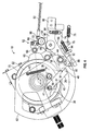
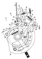
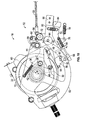
FIGS. 4-10 are side views of the clutch ofFIG. 1 , shown in various stages of operation. -
FIG. 11 is a perspective view of an actuation assembly portion of the clutch ofFIG. 1 . -
FIG. 12 is an exploded view of the actuation assembly ofFIG. 11 . - Before any embodiments of the disclosure are explained in detail, it is to be understood that the disclosure is not limited in its application to the details of construction and the arrangement of components set forth in the following description or illustrated in the following drawings. The disclosure is capable of other constructions and of being practiced or of being carried out in various ways. Directions such as clockwise and counterclockwise used herein are for illustrative purposes only.
- The disclosure relates to a
machine 10, such as a baler. In the illustrated construction, the disclosure relates to a square hay baler. In other constructions, the disclosure may relate to other types of balers, such as other extrusion type balers or non-extrusion type balers. In yet other constructions, the disclosure may relate to other types of machines, e.g., vehicles, tractors, other types of agricultural machines, forestry machines, mining machines, construction machines, machines for manufacturing, etc. - Referring to
FIGS. 1-2 , thebaler 10 has a series ofknotters 12 at generally the top of thebaler 10 which cooperate withtwine needles 14 that place strands of twine around a finished bale. Some components of theknotters 12 are not shown inFIG. 2 for simplicity. Theknotters 12 form a secure knot in the opposite ends of each twine strand and then cut the twine from the tied bale while retaining the free end of the twine for use in wrapping around the next bale. Abale length sensor 16, e.g., astar wheel 16, determines when a bale has reached full length, engages aclutch 18 that drivingly couples theknotters 12 with a rotatingdrive assembly 20, and causes the knotters to actuate for one single revolution. After each single revolution, theclutch 18 is disengaged until the next bale reaches the proper length. During each knotter cycle, theneedles 14 swing across a bale chamber located inside thebaler 10 to present the ends of twine strands to theknotters 12. In other constructions, thebale length sensor 16 may include other types of mechanical or electronic devices, such as optical sensors, cameras, presence sensors, timers, etc. - The
knotters 12 are supplied operating power through thedrive assembly 20, such as a chain drive assembly, ultimately from the power takeoff (PTO) of a tractor. In other constructions, thebaler 10 may have a dedicated power supply, such as an engine. Adrive member 22, which is a component of thedrive assembly 20, is constantly driven to rotate about an axis A, so long as power is being supplied to thebaler 10. Although thedrive member 22 is continuously driven, theknotters 12 are not driven unless theclutch 18 is engaged. - As shown in
FIGS. 2-10 , theclutch 18 includes a cam ring 32 projecting axially outwardly from an axial outer face of thedrive member 22 with respect to axis A. The cam ring 32 has an inner,annular surface 34 substantially concentric about the axis A. Adriving lug 30 with acontact surface 31 projects radially inwardly from thesurface 34. Anexternal stop 60 extends radially outwardly from an outerannular surface 70 of the cam ring 32 at a fixed angular distance (α) from the driving lug 30 (FIGS. 4 and10 ). - The
clutch 18 further includes adog 26 mounted on aclutch member 28. Theclutch member 28 presents areset cam surface 62 disposed generally circumferentially about an outer surface of theclutch member 28 and a needlelinkage attachment point 44 operably coupled with a needle linkage 46 (FIGS. 1 and2 ) secured to theneedles 14. - The
dog 26 includes a biasingmember attachment point 36, apivot 38, and anengagement member 40 carrying a follower, such as aroller 41 at a first end and having a retainingportion 48 at a second end. In other constructions, the follower may include a surface or other type of following member. The biasingmember attachment point 36, theroller 41, and theretaining portion 48 generally form a substantially triangular-shaped dog 26. Thepivot 38 is disposed substantially in line with theengagement member 40 and the biasingmember attachment point 36 within the triangular-shaped dog 26; however, in other constructions thepivot point 38 may be outside such that thedog 26 is shaped substantially as a 4-sided polygon. - The
dog 26 is coupled to theclutch member 28 at thepivot 38 and is pivotable between an engaged position (FIGS. 5-10 ) and a disengaged position (FIG. 4 ). In the engaged position, the engagement member 40 (and more specifically, the roller 41) of thedog 26 rides along the innerannular surface 34 of the cam ring 32 within a substantially circular path of travel of the movingdriving lug 30. When the drivinglug 30 meets theroller 41, the drivinglug 30 is drivingly mated with the dog 26 (FIG. 8 ) such that theclutch member 28 is engaged for actuating theknotters 12 andtwine needles 14. In the disengaged position, theengagement member 40 is lifted radially inward towards the axis A of rotation, creating a clearance so that the drivinglug 30 passes under theengagement member 40 without engaging theroller 41 such that theclutch member 28 is disengaged and theknotters 12 andtwine needles 14 are not actuated. Abiasing member 42 anchored to theclutch member 28 biases thedog 26 to the engaged position. In the illustrated construction, thebiasing member 42 includes a spring, such as a coil spring in the form of an extension spring or a compression spring. In other constructions, other types of springs may be employed and in yet other constructions, other types of biasing members may be used, such as elastic members, bands, counter weights, etc. - The
clutch 18 is engaged and disengaged by acontrol 96 that includes the bale length sensor 16 (seeFIG. 1 ). Thebale length sensor 16 is coupled to atrip linkage 50, which is in turn coupled to anactuation assembly 52 for holding thedog 26 in the disengaged position against the bias of thebiasing member 42 until thebale length sensor 16 trips theactuation assembly 52. - Referring to
FIGS. 11-12 , theactuation assembly 52 includes acontrol member 54, aretaining member 56, and aflex member 58 disposed between and linking thecontrol member 54 and the retainingmember 56. Thecontrol member 54 includes apivot 64 and afirst arm 66 extending generally away from thepivot 64. Thefirst arm 66 has a stop follower, such as astop roller 68, for timing the movement of thedog 26 into the engaged position relative to the drivinglug 30, as will be described in greater detail below. With reference toFIGS. 2-3 , thestop roller 68 and theouter surface 70 of the cam ring 32 are disposed substantially in the same plane substantially normal to the axis A. Thefirst arm 66 also includes a reset follower, such as areset roller 72, for returning the clutch 18 to the disengaged position. With reference toFIGS. 2-3 , thereset roller 72 and thereset cam surface 62 of theclutch member 28 are disposed in substantially the same plane substantially normal to the axis A. In other constructions, other types of followers may be employed. Thefirst arm 66 also includes acontrol attachment point 98 at which theactuation assembly 52 is attached to thecontrol 96. Specifically, thecontrol attachment point 98 is coupled to thetrip linkage 50. Asecond arm 74 and athird arm 76 of thecontrol member 54 both extend generally away from thepivot point 64 in directions different from thefirst arm 66. Thethird arm 76 is coupled to a biasingmember 78 for biasing theactuation assembly 52 to a released position, which will be described in greater detail below. - The
flex member 58 is coupled to thecontrol member 54 at thepivot 64. Thepivot 64 is also the pivot point for theactuation assembly 52 as a whole, which pivots about a pivot axis B.
Theflex member 58 includes afirst arm 80 and asecond arm 82, each extending generally away from thepivot 64 in substantially different directions. A biasingmember 84 couples thefirst arm 80 of theflex member 58 to thesecond arm 74 of thecontrol member 54 and biases thearms flex member 58 resiliently follows thecontrol member 54 and thecontrol member 54 resiliently follows theflex member 58 when one or the other pivots about the axis B. The biasingmember 84 allows for resilience and some relative movement between theflex member 58 and thecontrol member 54, e.g., in response to external stresses or accidental movement, as will be described in greater detail below. Thus, while theflex member 58 generally follows the pivoting movement of thecontrol member 54 and vice versa, some relative pivoting movement is allowed between theflex member 58 and thecontrol member 54 about thepivot 64. The biasingmember 84 preferably includes a compression spring disposed between washers on a rod coupled between thefirst arm 80 and thesecond arm 74, as shown inFIGS. 2-3 and11-12 . In other constructions, other biasingmembers 84 may be employed, as discussed above. For example, as shown inFIGS. 4-10 , an extension spring may be employed. Acounter weight 86 coupled to a distal end of thefirst arm 80 of theflex member 58 provides redundancy to the biasingmember 84 such that thecontrol member 54 and theflex member 58 are biased to follow each other as described above. Thecounter weight 86 also biases theactuation assembly 52 to a retaining position, which will be described in greater detail below. - The retaining
member 56 is pivotably coupled to a distal end of thesecond arm 82 of theflex member 58 at apivot 88. The retainingmember 56 includes anarcuate aperture 90 and adisengagement surface 91 for disengaging the clutch 18. Apin 92 fixed to thesecond arm 82 of theflex member 58 is received in thearcuate aperture 90. The retainingmember 56 is pivotable about an angular range defined by thearcuate aperture 90 and is biased by a biasingmember 94 towards thedog 26. The biasingmember 94 includes a compression spring coupled between the retainingmember 56 and theflex member 58; however, in other constructions, the biasingmember 94 may comprise other forms as described above. - The clutch 18 is configured such that the
external stop 60 is disposed proximate thestop roller 68 when the drivinglug 30, and more specifically thecontact surface 31, is disposed proximate theengagement member 40, and more specifically theroller 41, of thedog 26, e.g., an engagement location where the drivinglug 30 would meet theroller 41. This positional relationship determines the angular distance (α). In other words, the angular distance (α) is the angular distance between thestop roller 68 and the drivinglug 30 when thecontact surface 31 is disposed proximate theroller 41. As illustrated (seeFIGS. 4 and10 ), the angle α is between about 90 and about 180 degrees, and more specifically is between about 130 and about 140 degrees, and more specifically is about 135 degrees. In other constructions, the angle α may be different but is determined by the relative locations of thestop roller 68 and theengagement member 40 as discussed above. - In operation, the
trip linkage 50 holds theactuation assembly 52 in the retaining position against the bias of the biasingmember 78 while the bale is being formed in thebaler 10. - The retaining
member 56 is maintained against retainingportion 48 of thedog 26 and positions thedog 26 in the disengaged position against the force of the biasingmember 42. The retainingmember 56 resiliently engages the retainingportion 48 of thedog 26 due to the biasingmember 94 and the give provided by the retainingmember 56 being pivotably coupled to theflex arm 58. During engagement with the retainingportion 48, the retainingmember 56 may be in a partially flexed state as the forces of the biasingmembers drive member 22 is continuously rotating. The drivinglug 30 thus advances in a circular path of travel about the axis A in a counterclockwise direction. To the extent thedog 26 remains in the disengaged position (FIG. 4 ), drivinglug 30 passes radially outward from theroller 41 of thedog 26 during each revolution and the clutch 18 remains disengaged. - When the bale is formed, i.e., has reached a predetermined length as determined by the
bale length sensor 16, thetrip linkage 50 moves to release theactuation assembly 52 to the released position such that the biasingmember 78 pulls theactuation assembly 52 about thepivot 64 in a counterclockwise direction. Due to this pivoting, the retainingmember 56 separates from thedog 26, permitting the biasing member to inwardly pull theattachment point 36 such that the engagement member 40 (and the roller 41) of thedog 26 rotates about thepivot 38 towards the innerannular surface 34 of the drive member 22 (FIG. 5 ). As the retainingmember 56 separates from thedog 26, the biasingmember 94 forces the retainingmember 56 to a fully extended position (counterclockwise). When the drivinglug 30contact surface 31 reaches the roller 41 (FIG. 7 ), the drivinglug 30 drives thedog 26, which in turn drives theclutch member 28 through one operating cycle of 360 degrees to operate the aforementioned needles 14. During the operating cycle, thereset cam surface 62 engages the reset roller 72 (FIG. 10 ), which pivots theactuation assembly 52 clockwise about thepivot 64 to dispose the retainingmember 56 back into the path of the retainingportion 48 of thedog 26 when thedog 26 returns at the end of its revolution. Re-engagement of the retainingmember 56 with the retainingportion 48 rotates thedog 26 clockwise about thepivot 38 into its disengaged position, disengaging the clutch 18. The drivinglug 30 continues along its path of travel. - In the event that the
bale length sensor 16 attempts to release theactuation assembly 52 when the drivinglug 30 is just about to pass under the dog 26 (e.g., near the engagement position as shown inFIG. 4 ), release of theactuation assembly 52 is inhibited by theexternal stop 60 to deter a poor connection between the drivinglug 30 and thedog 26. As discussed above, theexternal stop 60 is disposed proximate thestop roller 68 by design in this condition. Specifically, in this position theexternal stop 60 engages thestop roller 68, thereby retaining theactuation assembly 52 in the retaining position regardless of activation of thetrip linkage 50 and allowing the drivinglug 30 to pass under thedog 26 without engagement. Once theexternal stop 60 clears the stop roller 68 (FIG. 5 ), theactuation assembly 52 is free to release as described above. That is, when the drivinglug 30 makes another revolution and approaches theengagement member 40 of the dog 26 (FIG. 6 ), engagement will occur as described above if thetrip linkage 50 has moved to release theactuation assembly 52. - Typically, when the
dog 26 becomes engaged with the drivinglug 30, the retainingportion 48 clears theactuation assembly 52. However, in some instances, the retainingportion 48 may run into theactuation assembly 52. For example, when engagement between thestop roller 68 and theexternal stop 60 drives thecontrol member 54 clockwise, theflex member 58 and the retainingmember 56 are also driven clockwise, potentially driving theflex member 58 and/or the retainingmember 56 into theengagement member 40 of thedog 26. Other possible reasons for interference between thedog 26 and theactuation assembly 52 include tolerance build-up, timing, vibrations, or other reasons. In any of these instances, to inhibit lock-up, binding, or damage to the components as thedog 26 is driven, theactuation assembly 52 flexes about thepivot 64 and/or thepivot 88 to make way for the dog 26 (FIGS. 7-8 ). Specifically, theflex member 58 pivots counterclockwise with respect to thecontrol member 54, i.e., such that thefirst arm 80 of theflex member 58 moves away from thesecond arm 74 of thecontrol member 54. Thecontrol member 54 may not be able to follow theflex member 58 in these instances due to engagement between thestop roller 68 and theexternal stop 60 inhibiting pivoting movement in that direction (counterclockwise). Thus, theflex member 58 allows theactuation assembly 52 to flex in on itself about the pivot 64 (FIGS. 7-8 ) to inhibit lock-up, binding, damage, etc. When thedog 26 is completely clear of theactuation assembly 52, then the biasingmember 84 and/or theweights 86 allow thecontrol member 54 and theflex member 58 to return to equilibrium to their relative angular positions with respect to each other, i.e., a neutral position (FIGS. 4-6 and9-10 ). Furthermore, the retainingmember 56 may also flex in these conditions. For example, the retainingmember 56 may rotate clockwise about thepivot 88 with respect to theflex member 58 to make way for the drivendog 26, thereby inhibiting lock-up, binding, damage, etc. - Thus, the disclosure provides, among other things, an actuation assembly for engaging and disengaging a clutch, the actuation assembly being capable of flexing to avoid binding with other driven components. While the above describes example embodiments of the present disclosure, these descriptions should not be viewed in a limiting sense. Rather, there are several variations and modifications which may be made without departing from the scope of the present disclosure as defined in the appended claims.
Claims (10)
- A clutch (18) for selectively driving a mechanism, the clutch (18) comprising:a driven rotating member (22) having a driving lug (30) positioned on an inner annular surface (31) and having an outer surface (70);a dog (26) movable between an engaged position for driving the mechanism and a disengaged position; andan actuation assembly (52) having a pivot (64) and movable between a retaining position for holding the dog (26) in the disengaged position and a release position for releasing the dog (26) to the engaged position, characterized in the actuation assembly (52) comprising
a first member (54) pivotable about the pivot (64) between the retaining position and the release position, the first member (54) having a follower (68) configured to selectively follow the outer surface (70) of the rotating member (22), and
a second member (58) pivotable about the pivot (64) between the retaining position and the release position, the second member (58) extending towards the dog (26) in the retaining position for holding the dog (26) in the disengaged position,
wherein the second member (58) is coupled to the first member (54) at the pivot (64) such that the first and second members (54, 58) are independently pivotable about the pivot (64) such that the actuation assembly (52) is capable of flexing about the pivot (64) to inhibit binding between the dog (26) and the actuation assembly (52). - The clutch (18) of claim 1, further comprising a driven rotating member (22) having a driving lug (30) positioned on an inner annular surface (31) and having an outer surface (70), wherein the dog (26) in its engaged position is driven by the driving lug (30) for driving the mechanism and the dog (26) in its disengaged position is disengaged from the driving lug (30).
- The clutch (18) of 2, further comprising a stop (60) disposed on an outer surface of the rotating member (22), wherein the follower (68) is configured to follow the outer surface (70) and the stop (68), wherein the first member (54) rotates about the pivot (64) as the follower (68) follows the stop (60).
- The clutch (18) of one of the claims 1 to 3, further comprising a biasing member (84) resiliently coupling the first member (54) and the second member (58) such that the first and second members (54, 58) resiliently follow each other and are biased to return to a neutral position with respect to each other.
- The clutch (18) of one of the claims 1 to 4, further comprising a counter weight (86) coupled to at least one of the first member (54) and/or the second member (58) for redundantly urging the first and second members (54, 58) to the neutral position with respect to each other.
- The clutch (18) of claim 4 or 5, wherein the biasing member (84) comprises a spring.
- The clutch (18) of one of the claims 1 to 6, further comprising a third member (56) pivotably coupled to the second member (58), the third member (56) having a surface (91) engaging the dog (26) to hold the dog (26) in the disengaged position.
- The clutch (18) of claim 7, further comprising a biasing member (94) coupled between the second and third members (58, 56) such that the third member (56) resiliently engages the dog (26) to hold the dog (26) in the disengaged position.
- The clutch (18) of one of the claims 1 to 8, wherein the first member (54) includes first and second arms (66, 74) generally extending from the pivot (64), the first arm being coupled to a control (96) at an attachment point (98), said control movable between a retaining position for holding the dog (26) in the disengaged position and a release position for releasing the dog (26) to the engaged position, wherein the second member (58) includes third and fourth arms (80, 82), the fourth arm (82) extending towards the dog (26) in the retaining position, the clutch (18) further comprising a biasing member resiliently coupling the second arm (74) and the third arm (80) such that the first and second members (54, 58) resiliently follow each other and are biased to return to a neutral position with respect to each other.
- The clutch (18) of claim 9, further comprising the counter weight (86) disposed on the third arm (80) for redundantly urging the first and second members (54, 58) to the retaining position.
Applications Claiming Priority (1)
| Application Number | Priority Date | Filing Date | Title |
|---|---|---|---|
| US14/494,188 US9585311B2 (en) | 2014-09-23 | 2014-09-23 | Clutch mechanism for a baler |
Publications (2)
| Publication Number | Publication Date |
|---|---|
| EP3000310A1 true EP3000310A1 (en) | 2016-03-30 |
| EP3000310B1 EP3000310B1 (en) | 2019-09-18 |
Family
ID=54105603
Family Applications (1)
| Application Number | Title | Priority Date | Filing Date |
|---|---|---|---|
| EP15181904.2A Active EP3000310B1 (en) | 2014-09-23 | 2015-08-21 | Clutch |
Country Status (4)
| Country | Link |
|---|---|
| US (1) | US9585311B2 (en) |
| EP (1) | EP3000310B1 (en) |
| AU (1) | AU2015227428B2 (en) |
| BR (1) | BR102015024233A2 (en) |
Cited By (2)
| Publication number | Priority date | Publication date | Assignee | Title |
|---|---|---|---|---|
| CN105850348A (en) * | 2016-05-30 | 2016-08-17 | 河南豪丰农业装备有限公司 | Straw bundling machine |
| EP4289255A1 (en) * | 2022-06-06 | 2023-12-13 | Deere & Company | Baler independent needle drive |
Families Citing this family (4)
| Publication number | Priority date | Publication date | Assignee | Title |
|---|---|---|---|---|
| US11382275B2 (en) | 2016-08-31 | 2022-07-12 | Tube-Line Manufacturing Limited | Continuous round baler accumulation chamber |
| CN106763280B (en) * | 2016-12-12 | 2018-12-11 | 郑州市顺意科技有限公司 | A kind of double acting clutch tire control device |
| BE1024940B1 (en) | 2017-06-20 | 2018-08-21 | Cnh Industrial Belgium Nv | BALEN PRESS WITH PROTECTION AGAINST OVERLOADING OF THE NEEDLES |
| US10701866B2 (en) | 2017-10-25 | 2020-07-07 | Deere & Company | Drive system for intermittent rotation output |
Citations (2)
| Publication number | Priority date | Publication date | Assignee | Title |
|---|---|---|---|---|
| EP0883986A1 (en) * | 1997-06-14 | 1998-12-16 | New Holland Belgium N.V. | Safety means for a needle trip mechanism |
| EP1131993A1 (en) * | 2000-03-06 | 2001-09-12 | HAY & FORAGE INDUSTRIES | Knotter reset arm relief mechanism |
Family Cites Families (4)
| Publication number | Priority date | Publication date | Assignee | Title |
|---|---|---|---|---|
| US2701517A (en) * | 1951-05-19 | 1955-02-08 | Ford Motor Co | Metering and trigger mechanism for bale tiers |
| US2807996A (en) * | 1955-07-26 | 1957-10-01 | Deere Mfg Co | Tying mechanism control for balers |
| US5782175A (en) | 1997-08-29 | 1998-07-21 | Hay & Forage Industries | Knotter clutch control for square balers |
| US20090139823A1 (en) * | 2007-11-29 | 2009-06-04 | Alden Joseph Dyer | Handlebar clutch-lever assist |
-
2014
- 2014-09-23 US US14/494,188 patent/US9585311B2/en active Active
-
2015
- 2015-08-21 EP EP15181904.2A patent/EP3000310B1/en active Active
- 2015-09-16 AU AU2015227428A patent/AU2015227428B2/en not_active Ceased
- 2015-09-21 BR BR102015024233A patent/BR102015024233A2/en active Search and Examination
Patent Citations (2)
| Publication number | Priority date | Publication date | Assignee | Title |
|---|---|---|---|---|
| EP0883986A1 (en) * | 1997-06-14 | 1998-12-16 | New Holland Belgium N.V. | Safety means for a needle trip mechanism |
| EP1131993A1 (en) * | 2000-03-06 | 2001-09-12 | HAY & FORAGE INDUSTRIES | Knotter reset arm relief mechanism |
Cited By (3)
| Publication number | Priority date | Publication date | Assignee | Title |
|---|---|---|---|---|
| CN105850348A (en) * | 2016-05-30 | 2016-08-17 | 河南豪丰农业装备有限公司 | Straw bundling machine |
| CN105850348B (en) * | 2016-05-30 | 2017-07-07 | 河南豪丰农业装备有限公司 | A kind of straw baler |
| EP4289255A1 (en) * | 2022-06-06 | 2023-12-13 | Deere & Company | Baler independent needle drive |
Also Published As
| Publication number | Publication date |
|---|---|
| AU2015227428A1 (en) | 2016-04-07 |
| AU2015227428B2 (en) | 2018-12-13 |
| US20160081277A1 (en) | 2016-03-24 |
| US9585311B2 (en) | 2017-03-07 |
| BR102015024233A2 (en) | 2016-03-29 |
| EP3000310B1 (en) | 2019-09-18 |
Similar Documents
| Publication | Publication Date | Title |
|---|---|---|
| EP3000310B1 (en) | Clutch | |
| CN106172285B (en) | Dual-bearing fishing reel | |
| JP5153269B2 (en) | Roller clutch | |
| US8590945B2 (en) | Double-knot twine-knotter unit for large bale presses with a plurality of double-knot twine-knotters assembled on one knotter driveshaft | |
| RU2018115359A (en) | Roulette leash for winding and unwinding the leash | |
| JP2009063052A5 (en) | ||
| EP2464210B1 (en) | Agricultural vehicle with an access panel latch | |
| US5782175A (en) | Knotter clutch control for square balers | |
| SE432510B (en) | DEVICE FOR DISCONNECTING AND RE-CONNECTING THE LINCH SPOIL AT A FISHING ROLL | |
| CA1057217A (en) | Clutch assembly | |
| EP1253315A2 (en) | Starters for internal combustion engine | |
| US2634840A (en) | Clutch trip mechanism for hay balers | |
| EP4289255A1 (en) | Baler independent needle drive | |
| US20250113777A1 (en) | Baler | |
| US6394245B2 (en) | Knotter reset arm relief mechanism | |
| US20080244914A1 (en) | Cable actuated indexing trimmer head compressor | |
| CN105454175A (en) | Anti-reverse device for fishing spinning reel | |
| CA2415117C (en) | Independently powered knotter and needle drive arrangement for a large rectangular baler | |
| US872663A (en) | Grain-binder. | |
| JPH099832A (en) | Clutch returning mechanism for double bearing reel | |
| JP7724167B2 (en) | Dual-bearing reel | |
| US366240A (en) | Grain-binder | |
| EP0429721B1 (en) | Clutch assembly | |
| US548723A (en) | Grain-binder | |
| US240432A (en) | locke |
Legal Events
| Date | Code | Title | Description |
|---|---|---|---|
| PUAI | Public reference made under article 153(3) epc to a published international application that has entered the european phase |
Free format text: ORIGINAL CODE: 0009012 |
|
| AK | Designated contracting states |
Kind code of ref document: A1 Designated state(s): AL AT BE BG CH CY CZ DE DK EE ES FI FR GB GR HR HU IE IS IT LI LT LU LV MC MK MT NL NO PL PT RO RS SE SI SK SM TR |
|
| AX | Request for extension of the european patent |
Extension state: BA ME |
|
| 17P | Request for examination filed |
Effective date: 20160930 |
|
| RBV | Designated contracting states (corrected) |
Designated state(s): AL AT BE BG CH CY CZ DE DK EE ES FI FR GB GR HR HU IE IS IT LI LT LU LV MC MK MT NL NO PL PT RO RS SE SI SK SM TR |
|
| GRAP | Despatch of communication of intention to grant a patent |
Free format text: ORIGINAL CODE: EPIDOSNIGR1 |
|
| STAA | Information on the status of an ep patent application or granted ep patent |
Free format text: STATUS: GRANT OF PATENT IS INTENDED |
|
| INTG | Intention to grant announced |
Effective date: 20190410 |
|
| GRAS | Grant fee paid |
Free format text: ORIGINAL CODE: EPIDOSNIGR3 |
|
| GRAA | (expected) grant |
Free format text: ORIGINAL CODE: 0009210 |
|
| STAA | Information on the status of an ep patent application or granted ep patent |
Free format text: STATUS: THE PATENT HAS BEEN GRANTED |
|
| AK | Designated contracting states |
Kind code of ref document: B1 Designated state(s): AL AT BE BG CH CY CZ DE DK EE ES FI FR GB GR HR HU IE IS IT LI LT LU LV MC MK MT NL NO PL PT RO RS SE SI SK SM TR |
|
| REG | Reference to a national code |
Ref country code: GB Ref legal event code: FG4D |
|
| REG | Reference to a national code |
Ref country code: CH Ref legal event code: EP |
|
| REG | Reference to a national code |
Ref country code: DE Ref legal event code: R096 Ref document number: 602015038127 Country of ref document: DE |
|
| REG | Reference to a national code |
Ref country code: AT Ref legal event code: REF Ref document number: 1180221 Country of ref document: AT Kind code of ref document: T Effective date: 20191015 |
|
| REG | Reference to a national code |
Ref country code: IE Ref legal event code: FG4D |
|
| REG | Reference to a national code |
Ref country code: NL Ref legal event code: MP Effective date: 20190918 |
|
| PG25 | Lapsed in a contracting state [announced via postgrant information from national office to epo] |
Ref country code: BG Free format text: LAPSE BECAUSE OF FAILURE TO SUBMIT A TRANSLATION OF THE DESCRIPTION OR TO PAY THE FEE WITHIN THE PRESCRIBED TIME-LIMIT Effective date: 20191218 Ref country code: NO Free format text: LAPSE BECAUSE OF FAILURE TO SUBMIT A TRANSLATION OF THE DESCRIPTION OR TO PAY THE FEE WITHIN THE PRESCRIBED TIME-LIMIT Effective date: 20191218 Ref country code: SE Free format text: LAPSE BECAUSE OF FAILURE TO SUBMIT A TRANSLATION OF THE DESCRIPTION OR TO PAY THE FEE WITHIN THE PRESCRIBED TIME-LIMIT Effective date: 20190918 Ref country code: HR Free format text: LAPSE BECAUSE OF FAILURE TO SUBMIT A TRANSLATION OF THE DESCRIPTION OR TO PAY THE FEE WITHIN THE PRESCRIBED TIME-LIMIT Effective date: 20190918 Ref country code: FI Free format text: LAPSE BECAUSE OF FAILURE TO SUBMIT A TRANSLATION OF THE DESCRIPTION OR TO PAY THE FEE WITHIN THE PRESCRIBED TIME-LIMIT Effective date: 20190918 Ref country code: LT Free format text: LAPSE BECAUSE OF FAILURE TO SUBMIT A TRANSLATION OF THE DESCRIPTION OR TO PAY THE FEE WITHIN THE PRESCRIBED TIME-LIMIT Effective date: 20190918 |
|
| REG | Reference to a national code |
Ref country code: LT Ref legal event code: MG4D |
|
| PG25 | Lapsed in a contracting state [announced via postgrant information from national office to epo] |
Ref country code: LV Free format text: LAPSE BECAUSE OF FAILURE TO SUBMIT A TRANSLATION OF THE DESCRIPTION OR TO PAY THE FEE WITHIN THE PRESCRIBED TIME-LIMIT Effective date: 20190918 Ref country code: RS Free format text: LAPSE BECAUSE OF FAILURE TO SUBMIT A TRANSLATION OF THE DESCRIPTION OR TO PAY THE FEE WITHIN THE PRESCRIBED TIME-LIMIT Effective date: 20190918 Ref country code: GR Free format text: LAPSE BECAUSE OF FAILURE TO SUBMIT A TRANSLATION OF THE DESCRIPTION OR TO PAY THE FEE WITHIN THE PRESCRIBED TIME-LIMIT Effective date: 20191219 Ref country code: AL Free format text: LAPSE BECAUSE OF FAILURE TO SUBMIT A TRANSLATION OF THE DESCRIPTION OR TO PAY THE FEE WITHIN THE PRESCRIBED TIME-LIMIT Effective date: 20190918 |
|
| REG | Reference to a national code |
Ref country code: AT Ref legal event code: MK05 Ref document number: 1180221 Country of ref document: AT Kind code of ref document: T Effective date: 20190918 |
|
| PG25 | Lapsed in a contracting state [announced via postgrant information from national office to epo] |
Ref country code: ES Free format text: LAPSE BECAUSE OF FAILURE TO SUBMIT A TRANSLATION OF THE DESCRIPTION OR TO PAY THE FEE WITHIN THE PRESCRIBED TIME-LIMIT Effective date: 20190918 Ref country code: NL Free format text: LAPSE BECAUSE OF FAILURE TO SUBMIT A TRANSLATION OF THE DESCRIPTION OR TO PAY THE FEE WITHIN THE PRESCRIBED TIME-LIMIT Effective date: 20190918 Ref country code: PL Free format text: LAPSE BECAUSE OF FAILURE TO SUBMIT A TRANSLATION OF THE DESCRIPTION OR TO PAY THE FEE WITHIN THE PRESCRIBED TIME-LIMIT Effective date: 20190918 Ref country code: RO Free format text: LAPSE BECAUSE OF FAILURE TO SUBMIT A TRANSLATION OF THE DESCRIPTION OR TO PAY THE FEE WITHIN THE PRESCRIBED TIME-LIMIT Effective date: 20190918 Ref country code: PT Free format text: LAPSE BECAUSE OF FAILURE TO SUBMIT A TRANSLATION OF THE DESCRIPTION OR TO PAY THE FEE WITHIN THE PRESCRIBED TIME-LIMIT Effective date: 20200120 Ref country code: IT Free format text: LAPSE BECAUSE OF FAILURE TO SUBMIT A TRANSLATION OF THE DESCRIPTION OR TO PAY THE FEE WITHIN THE PRESCRIBED TIME-LIMIT Effective date: 20190918 Ref country code: AT Free format text: LAPSE BECAUSE OF FAILURE TO SUBMIT A TRANSLATION OF THE DESCRIPTION OR TO PAY THE FEE WITHIN THE PRESCRIBED TIME-LIMIT Effective date: 20190918 Ref country code: EE Free format text: LAPSE BECAUSE OF FAILURE TO SUBMIT A TRANSLATION OF THE DESCRIPTION OR TO PAY THE FEE WITHIN THE PRESCRIBED TIME-LIMIT Effective date: 20190918 |
|
| PG25 | Lapsed in a contracting state [announced via postgrant information from national office to epo] |
Ref country code: IS Free format text: LAPSE BECAUSE OF FAILURE TO SUBMIT A TRANSLATION OF THE DESCRIPTION OR TO PAY THE FEE WITHIN THE PRESCRIBED TIME-LIMIT Effective date: 20200224 Ref country code: SM Free format text: LAPSE BECAUSE OF FAILURE TO SUBMIT A TRANSLATION OF THE DESCRIPTION OR TO PAY THE FEE WITHIN THE PRESCRIBED TIME-LIMIT Effective date: 20190918 Ref country code: CZ Free format text: LAPSE BECAUSE OF FAILURE TO SUBMIT A TRANSLATION OF THE DESCRIPTION OR TO PAY THE FEE WITHIN THE PRESCRIBED TIME-LIMIT Effective date: 20190918 Ref country code: SK Free format text: LAPSE BECAUSE OF FAILURE TO SUBMIT A TRANSLATION OF THE DESCRIPTION OR TO PAY THE FEE WITHIN THE PRESCRIBED TIME-LIMIT Effective date: 20190918 |
|
| REG | Reference to a national code |
Ref country code: DE Ref legal event code: R097 Ref document number: 602015038127 Country of ref document: DE |
|
| PLBE | No opposition filed within time limit |
Free format text: ORIGINAL CODE: 0009261 |
|
| STAA | Information on the status of an ep patent application or granted ep patent |
Free format text: STATUS: NO OPPOSITION FILED WITHIN TIME LIMIT |
|
| PG2D | Information on lapse in contracting state deleted |
Ref country code: IS |
|
| PG25 | Lapsed in a contracting state [announced via postgrant information from national office to epo] |
Ref country code: DK Free format text: LAPSE BECAUSE OF FAILURE TO SUBMIT A TRANSLATION OF THE DESCRIPTION OR TO PAY THE FEE WITHIN THE PRESCRIBED TIME-LIMIT Effective date: 20190918 Ref country code: IS Free format text: LAPSE BECAUSE OF FAILURE TO SUBMIT A TRANSLATION OF THE DESCRIPTION OR TO PAY THE FEE WITHIN THE PRESCRIBED TIME-LIMIT Effective date: 20200119 |
|
| 26N | No opposition filed |
Effective date: 20200619 |
|
| PG25 | Lapsed in a contracting state [announced via postgrant information from national office to epo] |
Ref country code: SI Free format text: LAPSE BECAUSE OF FAILURE TO SUBMIT A TRANSLATION OF THE DESCRIPTION OR TO PAY THE FEE WITHIN THE PRESCRIBED TIME-LIMIT Effective date: 20190918 |
|
| PG25 | Lapsed in a contracting state [announced via postgrant information from national office to epo] |
Ref country code: MC Free format text: LAPSE BECAUSE OF FAILURE TO SUBMIT A TRANSLATION OF THE DESCRIPTION OR TO PAY THE FEE WITHIN THE PRESCRIBED TIME-LIMIT Effective date: 20190918 |
|
| REG | Reference to a national code |
Ref country code: CH Ref legal event code: PL |
|
| GBPC | Gb: european patent ceased through non-payment of renewal fee |
Effective date: 20200821 |
|
| PG25 | Lapsed in a contracting state [announced via postgrant information from national office to epo] |
Ref country code: LU Free format text: LAPSE BECAUSE OF NON-PAYMENT OF DUE FEES Effective date: 20200821 Ref country code: CH Free format text: LAPSE BECAUSE OF NON-PAYMENT OF DUE FEES Effective date: 20200831 Ref country code: LI Free format text: LAPSE BECAUSE OF NON-PAYMENT OF DUE FEES Effective date: 20200831 |
|
| REG | Reference to a national code |
Ref country code: BE Ref legal event code: MM Effective date: 20200831 |
|
| PG25 | Lapsed in a contracting state [announced via postgrant information from national office to epo] |
Ref country code: GB Free format text: LAPSE BECAUSE OF NON-PAYMENT OF DUE FEES Effective date: 20200821 Ref country code: IE Free format text: LAPSE BECAUSE OF NON-PAYMENT OF DUE FEES Effective date: 20200821 Ref country code: BE Free format text: LAPSE BECAUSE OF NON-PAYMENT OF DUE FEES Effective date: 20200831 |
|
| PG25 | Lapsed in a contracting state [announced via postgrant information from national office to epo] |
Ref country code: TR Free format text: LAPSE BECAUSE OF FAILURE TO SUBMIT A TRANSLATION OF THE DESCRIPTION OR TO PAY THE FEE WITHIN THE PRESCRIBED TIME-LIMIT Effective date: 20190918 Ref country code: MT Free format text: LAPSE BECAUSE OF FAILURE TO SUBMIT A TRANSLATION OF THE DESCRIPTION OR TO PAY THE FEE WITHIN THE PRESCRIBED TIME-LIMIT Effective date: 20190918 Ref country code: CY Free format text: LAPSE BECAUSE OF FAILURE TO SUBMIT A TRANSLATION OF THE DESCRIPTION OR TO PAY THE FEE WITHIN THE PRESCRIBED TIME-LIMIT Effective date: 20190918 |
|
| PG25 | Lapsed in a contracting state [announced via postgrant information from national office to epo] |
Ref country code: MK Free format text: LAPSE BECAUSE OF FAILURE TO SUBMIT A TRANSLATION OF THE DESCRIPTION OR TO PAY THE FEE WITHIN THE PRESCRIBED TIME-LIMIT Effective date: 20190918 |
|
| PGFP | Annual fee paid to national office [announced via postgrant information from national office to epo] |
Ref country code: DE Payment date: 20250721 Year of fee payment: 11 |
|
| PGFP | Annual fee paid to national office [announced via postgrant information from national office to epo] |
Ref country code: FR Payment date: 20250825 Year of fee payment: 11 |