EP2999313A1 - Method and apparatus for automatically controlling a light source - Google Patents
Method and apparatus for automatically controlling a light source Download PDFInfo
- Publication number
- EP2999313A1 EP2999313A1 EP15173912.5A EP15173912A EP2999313A1 EP 2999313 A1 EP2999313 A1 EP 2999313A1 EP 15173912 A EP15173912 A EP 15173912A EP 2999313 A1 EP2999313 A1 EP 2999313A1
- Authority
- EP
- European Patent Office
- Prior art keywords
- light
- scene
- status information
- light effect
- scene condition
- Prior art date
- Legal status (The legal status is an assumption and is not a legal conclusion. Google has not performed a legal analysis and makes no representation as to the accuracy of the status listed.)
- Withdrawn
Links
Images




Classifications
-
- H—ELECTRICITY
- H05—ELECTRIC TECHNIQUES NOT OTHERWISE PROVIDED FOR
- H05B—ELECTRIC HEATING; ELECTRIC LIGHT SOURCES NOT OTHERWISE PROVIDED FOR; CIRCUIT ARRANGEMENTS FOR ELECTRIC LIGHT SOURCES, IN GENERAL
- H05B47/00—Circuit arrangements for operating light sources in general, i.e. where the type of light source is not relevant
- H05B47/10—Controlling the light source
- H05B47/175—Controlling the light source by remote control
-
- H—ELECTRICITY
- H05—ELECTRIC TECHNIQUES NOT OTHERWISE PROVIDED FOR
- H05B—ELECTRIC HEATING; ELECTRIC LIGHT SOURCES NOT OTHERWISE PROVIDED FOR; CIRCUIT ARRANGEMENTS FOR ELECTRIC LIGHT SOURCES, IN GENERAL
- H05B47/00—Circuit arrangements for operating light sources in general, i.e. where the type of light source is not relevant
- H05B47/10—Controlling the light source
- H05B47/105—Controlling the light source in response to determined parameters
- H05B47/115—Controlling the light source in response to determined parameters by determining the presence or movement of objects or living beings
-
- H—ELECTRICITY
- H05—ELECTRIC TECHNIQUES NOT OTHERWISE PROVIDED FOR
- H05B—ELECTRIC HEATING; ELECTRIC LIGHT SOURCES NOT OTHERWISE PROVIDED FOR; CIRCUIT ARRANGEMENTS FOR ELECTRIC LIGHT SOURCES, IN GENERAL
- H05B47/00—Circuit arrangements for operating light sources in general, i.e. where the type of light source is not relevant
- H05B47/10—Controlling the light source
- H05B47/105—Controlling the light source in response to determined parameters
- H05B47/115—Controlling the light source in response to determined parameters by determining the presence or movement of objects or living beings
- H05B47/125—Controlling the light source in response to determined parameters by determining the presence or movement of objects or living beings by using cameras
-
- Y—GENERAL TAGGING OF NEW TECHNOLOGICAL DEVELOPMENTS; GENERAL TAGGING OF CROSS-SECTIONAL TECHNOLOGIES SPANNING OVER SEVERAL SECTIONS OF THE IPC; TECHNICAL SUBJECTS COVERED BY FORMER USPC CROSS-REFERENCE ART COLLECTIONS [XRACs] AND DIGESTS
- Y02—TECHNOLOGIES OR APPLICATIONS FOR MITIGATION OR ADAPTATION AGAINST CLIMATE CHANGE
- Y02B—CLIMATE CHANGE MITIGATION TECHNOLOGIES RELATED TO BUILDINGS, e.g. HOUSING, HOUSE APPLIANCES OR RELATED END-USER APPLICATIONS
- Y02B20/00—Energy efficient lighting technologies, e.g. halogen lamps or gas discharge lamps
- Y02B20/40—Control techniques providing energy savings, e.g. smart controller or presence detection
Definitions
- the present disclosure relates to the field of electronic technologies, and more particularly, to a method and an apparatus for controlling a smart light.
- Smart lights are controllable light sources.
- a controller is used to control the smart light via manual operations.
- the manual operations are required to control the smart light, and the automatic control is not achieved.
- the control mode of the smart light in the related art is not intelligentized, and the control cannot be made according to changes of the scene statuses, thus limiting the applications of the smart light.
- embodiments of the present disclosure provide a method and an apparatus for controlling a smart light, which is used for realizing automatic and intellectualized control of the smart light.
- a method for controlling a smart light comprising the steps of:
- the method may further comprise the steps of:
- the status information includes communication event information of a target contact
- the step of judging whether the current scene complies with the scene condition according to the status information may comprise a step of:
- the communication event information of the target contact includes: sharing contents by the target contact on a network platform; or, receiving communications sent by the target contact.
- the status information includes moving object monitoring event information in a target region
- the step of judging whether the current scene complies with the scene condition according to the status information may comprise a step of:
- the status information includes device access event information in the target region, the device access event information including a device identity and a device access time;
- the step of judging whether the current scene complies with the scene condition according to the status information may comprise a step of:
- the status information includes time information
- the step of judging whether the current scene complies with the scene condition according to the status information may comprise a step of:
- the light effect parameter includes at least one of the following parameters:
- an apparatus for controlling a smart light comprising:
- the apparatus may further comprise:
- the status information includes communication event information of a target contact
- the judgment module may comprise:
- a first judgment submodule configured to judge whether a specific communication event is conducted by the target contact according to the communication event information.
- the communication event information of the target contact includes: sharing contents by the target contact on a network platform; or, receiving communications sent by the target contact.
- the status information includes moving object monitoring event information in a target region
- the judgment module may comprise:
- the status information includes device access event information in the target region, the device access event information including a device identity and a device access time;
- the judgment module may comprise:
- the status information includes time information
- the judgment module may comprise:
- the light effect parameter includes at least one of the following parameters:
- an apparatus for controlling a smart light comprising:
- a computer program is provided according to a fourth aspect of the present disclosure.
- the computer program performs the steps of the method for controlling a smart light when this program is executed by a computer.
- This program can use any programming language and take the form of source code, object code or a code intermediate between source code and object code, such as a partially compiled form, or any other desirable form.
- the invention is also directed to a computer-readable information medium containing instructions of the computer program as described above.
- the information medium can be any entity or device capable of storing the program.
- the support can include storage means such as a ROM, for example a CD ROM or a microelectronic circuit ROM, or magnetic storage means, for example a diskette (floppy disk) or a hard disk.
- the information medium can be an integrated circuit in which the program is incorporated, the circuit being adapted to execute the method in question or to be used in its execution.
- the present disclosure may make corresponding controls according to changes of the scene statuses so as to realize intellectualized control of the smart light and expand the applications of the smart light; and enable the control of the smart light free from manual operation, realize automatic control of the smart light, and make the smart light control more convenient.
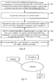
- Fig. 1 is a flow chart of a method for controlling a smart light, according to an exemplary embodiment.
- the method may be applied, for example, in a cloud server, a router, a personal computer, and a terminal device. As shown in Fig. 1 , the method comprises the following steps.
- step S101 status information of a current scene is acquired.
- step S101 the status information of the current scene may either be acquired from another device or be acquired locally, which is not specially limited in the present disclosure.
- step S102 whether the current scene complies with a scene condition is judged according to the status information.
- the method may also include: receiving and storing a scene condition and a light effect parameter corresponding to this scene condition that are set by a user.
- the user may set a scene condition and a light effect parameter corresponding to this scene condition in an application in a terminal, and the terminal sends to a device implementing the method (for example, a cloud server) the scene condition and light effect parameter; after receiving the scene condition and the light effect parameter sent by the terminal, the device stores the received scene condition and light effect parameter corresponding to the scene condition.
- a device implementing the method for example, a cloud server
- the scene condition and the light effect parameter corresponding to the scene condition may also be acquired through other manners, for example, by reading a local configuration file and acquiring a scene condition and a light effect parameter corresponding to this scene condition from the configuration file.
- the status information may include communication event information of a target contact.
- the step S102 may comprise a step of: judging whether a specific communication event is conducted by a target contact according to communication event information.
- the communication event information of the target contact may include: sharing contents by the target contact on a network platform; receiving communications sent from the target contact.
- the network platform refers to a social website
- the target contact refers to a account number
- sharing contents refers to publishing an article
- the scene condition refers to a condition wherein an account number of a social website publishes an article.
- step S101 communication event information, sent by a social website, of an account number publishing an article on a social website is received; in step S102, it is judged, according to the communication event information, that the account number publishes an article on the social website, and then it is determined that the status information of the current scene complies with a scene condition.
- the scene condition refers to a condition wherein the target contact sends communications.
- the communication event information of receiving communications sent by the target contact is acquired.
- step S102 it is judged, according to the acquired communication event information, that communications sent by the target contact is received, and then it is determined that the status information of the current scene complies with the scene condition.
- the status information includes moving object monitoring event information in a target region.
- the step S102 may include: judging whether a monitored moving object is passes into a target region according to the moving object monitoring event information.
- the scene condition refers to a condition wherein a monitored person passes into a target region; in this case in step S101, the moving object monitoring event information that a monitored person passes into a target region is received; in step S102, it is judged, according to the moving object monitoring event information, that the monitored person passes into the target region, and then it is determined that the current scene complies with the scene condition.
- the status information includes device access event information in a target region, the device access event information including an identity and an access time of a device.
- the step S102 may include: judging whether a first access (for example, access to a smart device in the target region) of a specific device is conducted in the target region within a preset duration according to the device access event information.
- the scene condition refers to a condition wherein a user carrying a specific smartband goes back home.
- step S101 the device access event information of access of the smartband sent by a smart box at home is received, the device access event information including an ID and an access time of the smartband; in step S102, is judged according to the ID and the access time of the smartband included in the of the access event information, whether it is the first access of the smartband at home within a preset duration; if it is judged that it is the first access of the smartband at home within the duration, the current scene is determined to comply with the scene condition.
- the status information includes time information.
- the step S102 may include: judging whether the current time reaches a preset time according to the time information.
- step S102 after judging that it is the first access of a specific device in a target region within a duration according to the device access event information, whether the current time reaches the preset time is judged according to the time information; if the current time reaches the preset time, the current scene is determined to comply with a scene condition.
- the scene condition refers to a condition wherein the current time reaches a preset time.
- the step S102 if it is judged that the current time reaches the preset time according to the time information, the current scene is determined to comply with the scene condition.
- step S102 in the embodiments is not limited thereto.
- step S103 when the current scene complies with the scene condition, a pre-stored light effect configuration library is inquired according to the scene condition and a light control instruction corresponding to the scene condition is generated.
- the light control instruction includes a light effect parameter enabling the smart light to present a light effect
- the pre-stored light effect configuration library includes a plurality of preset scene conditions and light effect parameters corresponding to respective preset scene conditions.
- the light effect parameter includes at least one of the following parameters: a light on-off parameter, a light flicker times parameter, a light color parameter and a light intensity parameter.
- step S104 the generated light control instruction is sent to the smart light so that the smart light presents a light effect corresponding to the scene condition.
- the present disclosure may make corresponding controls according to changes of the scene statuses so as to realize intellectualized control of the smart light and to expand the applications of the smart light; and enable the control of the smart light free from manual operation, realize automatic control of the smart light, and make the smart light control more convenient.
- Fig. 2 is a flow chart of a method for controlling a smart light, according to a first exemplary embodiment.
- Fig. 3 is an application scene diagram of the method for controlling the smart light, according to the first exemplary embodiment.
- the first embodiment is applied in the following scene: a cloud server is connected to a social website B, a terminal and a smart light L1 through network, and a user sets a scene condition in a terminal application as a condition wherein an account number A publishes an article on the social website B, and sets a corresponding light effect parameter as that the smart light L1 flickers for n1 times.
- the method in the first embodiment is applied to the cloud server, including the following steps.
- step S201 the scene condition and the light effect parameter corresponding to the scene condition sent by the terminal are received, and the scene condition and the light effect parameter corresponding to the scene condition are stored in a pre-stored light effect configuration library.
- step S202 communication event information that the account number A publishes an article on the social website B is received from the social website B,.
- step S203 the communication event of publishing an article on the social website B is judged to be conducted by the account number A according to the received communication event information, and then the current scene is determined to comply with the scene condition.
- step S204 the pre-stored light effect configuration library is inquired according to the scene condition, the inquired light effect parameter being flickering for n1 times, and a light control instruction including the light effect parameter of flickering for n1 times is generated.
- step S205 the generated light control instruction is sent to the smart light L1 so that the smart light L1 flickers for n1 times.
- the first embodiment has the following advantageous effects: after the target contact publishes an article on the preset website, the smart light is controlled to flicker, thus capable of prompting the user that the target contact publishes an article. It is convenient for the user to view the article published by the target contact on the website in time. In the first embodiment, control of the smart light is associated with the article being published on the website, thus further expanding the application range of the smart light.
- Fig. 4 is a flow chart of a method for controlling a smart light, according to a second exemplary embodiment.
- Fig. 5 is an application scene diagram of the method for controlling the smart light, according to the second exemplary embodiment.
- the second embodiment is applied in the following scene: a cloud server is connected to a monitor, a terminal and a smart light L1 through network, and a user sets a scene condition in a terminal application as a condition wherein a person, monitored by the monitor, passes into a target region, and sets a corresponding light effect as that the smart light L1 flickers for n2 times.
- the method in the second embodiment is applied to the cloud server, including the following steps.
- step S401 the scene condition and the light effect parameter corresponding to the scene condition sent by the terminal are received, and the scene condition and the light effect parameter corresponding to the scene condition are stored in a pre-stored light effect configuration library.
- step S402 moving object monitoring event information sent by the monitor in a target region is received.
- step S403 the monitored person passes into the target region is judged according to the received moving object monitoring event information, then the current scene is determined to comply with the scene condition.
- step S404 the pre-stored light effect configuration library is inquired according to the scene condition, the inquired light effect parameter being flickering for n2 times, and a light control instruction including the light effect parameter of flickering for n2 times is generated.
- step S405 the generated light control instruction is sent to the smart light L1 so that the smart light L1 flickers for n2 times.
- the second embodiment has the following advantageous effects: when detecting that a person passes into a target region, the smart light is controlled to flicker, thus capable of alarming when a person passes, so as to implement smart home.
- Fig. 6 is a flow chart of a method for controlling a smart light, according to a third exemplary embodiment.
- Fig. 7 is an application scene diagram of the method for controlling the smart light, according to the third exemplary embodiment.
- the third embodiment is applied in the following scene: a cloud server is connected to a smart box having a bluetooth communication device, a terminal and a smart light L1 through network, the smart box is located at a user's home; and the user sets a scene condition in a terminal application as a condition wherein the user carrying a smartband C goes back home and wherein the time reaches a preset moment T1, and sets a corresponding light effect as that the smart light L1 is turned on, and the smartband C has a bluetooth communication device.
- the method in the third embodiment is applied to the cloud server, including the following steps.
- step S601 the scene condition and the light effect parameter corresponding to the scene condition sent by the terminal are received, and the scene condition and the light effect parameter corresponding to the scene condition are stored in a pre-stored light effect configuration library.
- step S602 device access event information sent by the smart box located at home is received, and time information is acquired.
- the device access event information includes an identity and an access time of the smartband C.
- the smartband accesses to the smart box, and the identity (for example, a type and a serial number are taken as the identity) and the access time of the smartband are acquired, and the device access event information including the identity and the access time of the smartband is generated.
- identity for example, a type and a serial number are taken as the identity
- the device access event information including the identity and the access time of the smartband is generated.
- step S603 whether a first access of the smartband C being conducted at home within a duration is judged according to the device access event information, and if it is judged that it is the first access of the smartband C at home within the duration, step S604 is performed.
- step S604 whether the current time reaches a preset time T1 is judged according to the time information, and if the current time reaches the preset time T1, the current scene is determined to comply with the scene condition.
- step S605 the pre-stored light effect configuration library is inquired according to the scene condition, the inquired light effect parameter being turning on the smart light, and a light control instruction including the light effect parameter of turning on the smart light is generated.
- step S606 the generated light control instruction is sent to the smart light L1 so that the smart light L1 is turned on.
- the third embodiment has the following advantageous effects: when detecting that the user goes back home, the smart light is controlled to turn on at the preset moment, thus capable of automatically turning the smart light on for lighting when the user goes back home.
- the intelligentized lighting is realized so as to implement smart home.
- Fig. 8 is a flow chart of a method for controlling a smart light, according to a fourth exemplary embodiment.
- Fig. 9 is an application scene diagram of the method for controlling a smart light, according to the fourth exemplary embodiment.
- the fourth embodiment is applied in the following scene: a cloud server is connected to a terminal and a smart light L1 through network, and a user sets in a terminal application a scene condition as a condition wherein the time reaches a preset moment T2, and a corresponding light effect as that the smart light L1 flickers for n4 times.
- the method in the fourth embodiment is applied to the cloud server, including the following steps.
- step S801 the scene condition and the light effect parameter corresponding to the scene condition sent by the terminal are received, and the scene condition and the light effect parameter corresponding to the scene condition are stored in a pre-stored light effect configuration library.
- step S802 time information of the current moment is acquired.
- step S803 when the time in the time information is the same as the preset moment T2, the current scene is judged to comply with the scene condition.
- step S804 the pre-stored light effect configuration library is inquired according to the scene condition, the inquired light effect parameter being flickering for n4 times, and a light control instruction including the light effect parameter of flickering for n4 times is generated.
- step S805 the generated light control instruction is sent to the smart light L1 so that the smart light L1 flickers for n4 times.
- the fourth embodiment has the following advantageous effects: when the time reaches the preset moment, the smart light is controlled to flicker, thus capable of realizing an alarm clock function, and further expanding the application range of the smart light.
- applying the method in the cloud server is taken as example, but the present disclosure is not limited thereto.
- the method in the present disclosure may be applied in various devices, which is not specially limited herein.
- light flickering and light turning on are taken as example for the light effect, but the present disclosure is not limited thereto.
- the light effect in the present disclosure may include various effects, which is not specially limited herein.
- a plurality of scene conditions may be sent at the same time, and the method of the present disclosure may be implemented as: acquiring the status information of the current scene, judging whether the current scene complies with the scene condition according to the status information, and when the current scene complies with the scene condition, controlling the smart light according to the light effect corresponding to the complied scene condition.
- Fig. 10 is a block diagram of an apparatus for controlling a smart light, according to an exemplary embodiment, including:
- the apparatus further includes:
- the status information may include communication event information of a target contact
- the judgment module may include:
- the communication event information of the target contact may include: sharing contents by the target contact on a network platform; or, receiving communications sent by the target contact.
- the status information includes moving object monitoring event information in a target region
- the judgment module may include:
- the status information may include device access event information in a target region, the device access event information including an identity and an access time of the device;
- the judgment module may include:
- the status information may include time information
- the judgment module may include:
- the light effect parameter may include at least one of the following parameters:
- the present disclosure may make corresponding controls according to changes of the scene condition so as to realize intellectualized control of the smart light and expand the applications of the smart light; and enable the control of the smart light free from manual operation, realize automatic control of the smart light, and make the smart light control more convenient.
- Fig. 12 is a block diagram of an apparatus 1200 for controlling a smart light, according to an exemplary embodiment.
- the apparatus is suitable for a terminal device.
- the apparatus 1200 may be a mobile phone, a computer, a digital broadcast terminal, a messaging device, a gaming console, a tablet, a medical device, exercise equipment, a personal digital assistant, and the like.
- the apparatus 1200 may include one or more of the following components: a processing component 1202, a memory 1204, a power component 1206, a multimedia component 1208, an audio component 1210, an input/output (I/O) interface 1212, a sensor component 1214, and a communication component 1216.
- a processing component 1202 a memory 1204, a power component 1206, a multimedia component 1208, an audio component 1210, an input/output (I/O) interface 1212, a sensor component 1214, and a communication component 1216.
- the processing component 1202 typically controls overall operations of the apparatus 1200, such as the operations associated with display, telephone calls, data communications, camera operations, and recording operations.
- the processing component 1202 may include one or more processors 1220 to execute instructions to perform all or part of the steps in the above described methods.
- the processing component 1202 may include one or more modules which facilitate the interaction between the processing component 1202 and other components.
- the processing component 1202 may include a multimedia module to facilitate the interaction between the multimedia component 1208 and the processing component 1202.
- the memory 1204 is configured to store various types of data to support the operation of the apparatus 1200. Examples of such data include instructions for any applications or methods operated on the apparatus 1200, contact data, phonebook data, messages, pictures, video, etc.
- the memory 1204 may be implemented using any type of volatile or non-volatile memory devices, or a combination thereof, such as a static random access memory (SRAM), an electrically erasable programmable read-only memory (EEPROM), an erasable programmable read-only memory (EPROM), a programmable read-only memory (PROM), a read-only memory (ROM), a magnetic memory, a flash memory, a magnetic or optical disk.
- SRAM static random access memory
- EEPROM electrically erasable programmable read-only memory
- EPROM erasable programmable read-only memory
- PROM programmable read-only memory
- ROM read-only memory
- magnetic memory a magnetic memory
- flash memory a flash memory
- magnetic or optical disk a magnetic
- the power component 1206 provides power to various components of the apparatus 1200.
- the power component 1206 may include a power management system, one or more power sources, and any other components associated with the generation, management, and distribution of power in the apparatus 1200.
- the multimedia component 1208 includes a screen providing an output interface between the apparatus 1200 and the user.
- the screen may include a liquid crystal display (LCD) and a touch panel (TP). If the screen includes the touch panel, the screen may be implemented as a touch screen to receive input signals from the user.
- the touch panel includes one or more touch sensors to sense touches, swipes, and gestures on the touch panel. The touch sensors may not only sense a boundary of a touch or swipe action, but also sense a period of time and a pressure associated with the touch or swipe action.
- the multimedia component 1208 includes a front camera and/or a rear camera.
- the front camera and/or the rear camera may receive an external multimedia datum while the apparatus 1200 is in an operation mode, such as a photographing mode or a video mode.
- an operation mode such as a photographing mode or a video mode.
- Each of the front camera and the rear camera may be a fixed optical lens system or have focus and optical zoom capability.
- the audio component 1210 is configured to output and/or input audio signals.
- the audio component 1210 includes a microphone ("MIC") configured to receive an external audio signal when the apparatus 1200 is in an operation mode, such as a call mode, a recording mode, and a voice recognition mode.
- the received audio signal may be further stored in the memory 1204 or transmitted via the communication component 1216.
- the audio component 1210 further includes a speaker to output audio signals.
- the I/O interface 1212 provides an interface between the processing component 1202 and peripheral interface modules, such as a keyboard, a click wheel, buttons, and the like.
- the buttons may include, but are not limited to, a home button, a volume button, a starting button, and a locking button.
- the sensor component 1214 includes one or more sensors to provide status assessments of various aspects of the apparatus 1200. For instance, the sensor component 1214 may detect an open/closed status of the apparatus 1200, relative positioning of components, e.g., the display and the keypad, of the apparatus 1200, a change in position of the apparatus 1200 or a component of the apparatus 1200, a presence or absence of user contact with the apparatus 1200, an orientation or an acceleration/deceleration of the apparatus 1200, and a change in temperature of the apparatus 1200.
- the sensor component 1214 may include a proximity sensor configured to detect the presence of nearby objects without any physical contact.
- the sensor component 1214 may also include a light sensor, such as a CMOS or CCD image sensor, for use in imaging applications.
- the sensor component 1214 may also include an accelerometer sensor, a gyroscope sensor, a magnetic sensor, a pressure sensor, or a temperature sensor.
- the communication component 1216 is configured to facilitate communication, wired or wirelessly, between the apparatus 1200 and other devices.
- the apparatus 1200 can access a wireless network based on a communication standard, such as WiFi, 2G, or 3G, or a combination thereof.
- the communication component 1216 receives a broadcast signal or broadcast associated information from an external broadcast management system via a broadcast channel.
- the communication component 1216 further includes a near field communication (NFC) module to facilitate short-range communications.
- the NFC module may be implemented based on a radio frequency identification (RFID) technology, an infrared data association (IrDA) technology, an ultra-wideband (UWB) technology, a Bluetooth (BT) technology, and other technologies.
- RFID radio frequency identification
- IrDA infrared data association
- UWB ultra-wideband
- BT Bluetooth
- the apparatus 1200 may be implemented with one or more application specific integrated circuits (ASICs), digital signal processors (DSPs), digital signal processing devices (DSPDs), programmable logic devices (PLDs), field programmable gate arrays (FPGAs), controllers, micro-controllers, microprocessors, or other electronic components, for performing the above described methods.
- ASICs application specific integrated circuits
- DSPs digital signal processors
- DSPDs digital signal processing devices
- PLDs programmable logic devices
- FPGAs field programmable gate arrays
- controllers micro-controllers, microprocessors, or other electronic components, for performing the above described methods.
- non-transitory computer readable storage medium including instructions, such as included in the memory 1204, executable by the processor 820 in the apparatus 1200, for performing the above-described methods.
- the non-transitory computer-readable storage medium may be a ROM, a RAM, a CD-ROM, a magnetic tape, a floppy disc, an optical data storage device, and the like.
- An apparatus for controlling a smart light includes:
- the processor is also configured to: receive and store the preset scene condition and the light effect parameter corresponding to the preset scene condition that are set by a user.
- the status information includes communication event information of a target contact
- the processor may be configured to: judge whether a specific communication event is conducted by the target contact according to the communication event information.
- the status information includes moving object monitoring event information in a target region
- the processor may be configured to: judge whether a moving object is monitored to pass in the target region according to the moving object monitoring event information.
- the status information includes device access event information in the target region, the device access event information including a device identity and a device access time;
- the processor may be configured to: judge whether a first access of a specific device is conducted in the target region within a preset duration according to the device access event information.
- the status information includes time information
- the processor may be configured to: judge whether the current time reaches a preset time according to the time information.
- a non-transitory computer readable storage medium when an instruction in a storage medium is performed by a processor of a mobile terminal, enables the mobile terminal to perform a method for controlling a smart light, wherein the method includes:
- the light control instruction includes a light effect parameter enabling the smart light to present a preset light effect
- the light effect configuration library includes a plurality of preset scene conditions and light effect parameters corresponding to respective preset scene conditions
- the method may further include:
- the status information includes communication event information of a target contact
- the judging whether the current scene complies with the preset scene condition according to the status information may include:
- the communication event information of the target contact may include: sharing contents by the target contact on a preset network platform; or, receiving communications sent by the target contact.
- the status information may include moving object monitoring event information in a target region
- the judging whether the current scene complies with the preset scene condition according to the status information may include:
- the status information may include device access event information in the target region, the device access event information including a device identity and a device access time; and
- the judging whether the current scene complies with the preset scene condition according to the status information may include:
- the status information may include time information
- the judging whether the current scene complies with the preset scene condition according to the status information may include:
- a light on-off parameter a light flicker times parameter, a light color parameter and a light intensity parameter.
Landscapes
- Circuit Arrangement For Electric Light Sources In General (AREA)
- Telephone Function (AREA)
- Telephonic Communication Services (AREA)
Abstract
Description
- The present disclosure relates to the field of electronic technologies, and more particularly, to a method and an apparatus for controlling a smart light.
- Smart lights are controllable light sources. In the prior art, a controller is used to control the smart light via manual operations. Apparently, in the prior art, the manual operations are required to control the smart light, and the automatic control is not achieved. Moreover, the control mode of the smart light in the related art is not intelligentized, and the control cannot be made according to changes of the scene statuses, thus limiting the applications of the smart light.
- In order to overcome the problems in the prior art, embodiments of the present disclosure provide a method and an apparatus for controlling a smart light, which is used for realizing automatic and intellectualized control of the smart light.
- According to a first aspect of embodiments of the present disclosure, there is provided a method for controlling a smart light, comprising the steps of:
- acquiring status information of a current scene;
- judging whether the current scene complies with a scene condition according to the status information;
- inquiring a pre-stored light effect configuration library according to the scene condition and generating a light control instruction corresponding to the scene condition if the current scene complies with the scene condition, wherein the light control instruction includes a light effect parameter enabling the smart light to present a light effect, and the light effect configuration library includes a plurality of preset scene conditions and light effect parameters corresponding to respective preset scene conditions; and
- sending the generated light control instruction to the smart light so that the smart light presents a light effect corresponding to the scene condition.
- In one embodiment, the method may further comprise the steps of:
- receiving and storing the scene condition and the light effect parameter corresponding to the scene condition that are set by a user.
- In one embodiment, the status information includes communication event information of a target contact; and
- the step of judging whether the current scene complies with the scene condition according to the status information may comprise a step of:
- judging whether a specific communication event is conducted by the target contact according to the communication event information.
- In one embodiment, the communication event information of the target contact includes: sharing contents by the target contact on a network platform; or, receiving communications sent by the target contact.
- In one embodiment, the status information includes moving object monitoring event information in a target region; and
- the step of judging whether the current scene complies with the scene condition according to the status information may comprise a step of:
- judging whether a monitored moving object passes into the target region according to the moving object monitoring event information.
- In one embodiment, the status information includes device access event information in the target region, the device access event information including a device identity and a device access time; and
- the step of judging whether the current scene complies with the scene condition according to the status information may comprise a step of:
- judging whether a first access of a specific device is conducted in the target region within a duration according to the device access event information.
- In one embodiment, the status information includes time information; and
- the step of judging whether the current scene complies with the scene condition according to the status information may comprise a step of:
- judging whether a current time reaches a preset time according to the time information.
- In one embodiment, the light effect parameter includes at least one of the following parameters:
- a light on-off parameter, a light flicker times parameter, a light color parameter and a light intensity parameter.
- According to a second aspect of embodiments of the present disclosure, there is provided an apparatus for controlling a smart light, comprising:
- an acquisition module configured to acquire status information of a current scene;
- a judgment module configured to judge whether the current scene complies with a scene condition according to the status information;
- a generation module configured to inquire a pre-stored light effect configuration library according to the scene condition and generate a light control instruction corresponding to the scene condition if the judgment module judges that the current scene complies with the scene condition, wherein the light control instruction includes a light effect parameter enabling the smart light to present a light effect, and the pre-stored light effect configuration library includes a plurality of preset scene conditions and light effect parameters corresponding to respective preset scene conditions; and
- a sending module configured to send the light control instruction generated by the generation module to the smart light so that the smart light presents a light effect corresponding to the scene condition.
- In one embodiment, the apparatus may further comprise:
- a storage module configured to receive and store the scene condition and a light effect parameter corresponding to the scene condition that are set by a user.
- In one embodiment, the status information includes communication event information of a target contact; and
- the judgment module may comprise:
- a first judgment submodule configured to judge whether a specific communication event is conducted by the target contact according to the communication event information.
- In one embodiment, the communication event information of the target contact includes: sharing contents by the target contact on a network platform; or, receiving communications sent by the target contact.
- In one embodiment, the status information includes moving object monitoring event information in a target region; and
- the judgment module may comprise:
- a second judgment submodule configured to judge whether a monitored moving object passes into the target region according to the moving object monitoring event information.
- In one embodiment, the status information includes device access event information in the target region, the device access event information including a device identity and a device access time; and
- the judgment module may comprise:
- a third judgment submodule configured to judge whether a first access of a specific device is conducted in the target region within a duration according to the device access event information.
- In one embodiment, the status information includes time information; and
- the judgment module may comprise:
- a fourth judgment submodule configured to judge whether a current time reaches a preset time according to the time information.
- In one embodiment, the light effect parameter includes at least one of the following parameters:
- a light on-off parameter, a light flicker times parameter, a light color parameter and a light intensity parameter.
- According to a third aspect of the present disclosure, there is provided an apparatus for controlling a smart light, comprising:
- a processor; and
- a memory for storing instructions executable by the processor;
- wherein the processor is configured to:
- acquire status information of a current scene;
- judge whether the current scene complies with a scene condition according to the status information;
- inquire a pre-stored light effect configuration library according to the scene condition and generate a light control instruction corresponding to the scene condition if the current scene complies with the scene condition, wherein the light control instruction includes a light effect parameter enabling the smart light to present a light effect, and the light effect configuration library includes a plurality of preset scene conditions and light effect parameters corresponding to respective preset scene conditions; and
- send the generated light control instruction to the smart light so that the smart light presents a light effect corresponding to the scene condition.
- A computer program is provided according to a fourth aspect of the present disclosure. The computer program performs the steps of the method for controlling a smart light when this program is executed by a computer.
- This program can use any programming language and take the form of source code, object code or a code intermediate between source code and object code, such as a partially compiled form, or any other desirable form.
- The invention is also directed to a computer-readable information medium containing instructions of the computer program as described above.
- The information medium can be any entity or device capable of storing the program. For example, the support can include storage means such as a ROM, for example a CD ROM or a microelectronic circuit ROM, or magnetic storage means, for example a diskette (floppy disk) or a hard disk.
- Alternatively, the information medium can be an integrated circuit in which the program is incorporated, the circuit being adapted to execute the method in question or to be used in its execution.
- The technical solutions provided by the embodiments of the present disclosure may include the following advantageous effects: the present disclosure may make corresponding controls according to changes of the scene statuses so as to realize intellectualized control of the smart light and expand the applications of the smart light; and enable the control of the smart light free from manual operation, realize automatic control of the smart light, and make the smart light control more convenient.
- It is to be understood that both the foregoing general description and the following detailed description are exemplary and explanatory only and are not restrictive of the invention.
- The accompanying drawings, which are incorporated in and constitute a part of this specification, illustrate embodiments consistent with the invention and, together with the description, serve to explain the principles of the invention.
-
Fig. 1 is a flow chart of a method for controlling a smart light, according to an exemplary embodiment. -
Fig. 2 is a flow chart of a method for controlling a smart light, according to a first exemplary embodiment. -
Fig. 3 is an application scene diagram of the method for controlling the smart light, according to the first exemplary embodiment. -
Fig. 4 is a flow chart of a method for controlling a smart light, according to a second exemplary embodiment. -
Fig. 5 is an application scene diagram of the method for controlling the smart light, according to the second exemplary embodiment. -
Fig. 6 is a flow chart of a method for controlling a smart light, according to a third exemplary embodiment. -
Fig. 7 is an application scene diagram of the method for controlling the smart light, according to the third exemplary embodiment. -
Fig. 8 is a flow chart of a method for controlling a smart light, according to a fourth exemplary embodiment. -
Fig. 9 is an application scene diagram of the method for controlling the smart light, according to the fourth exemplary embodiment. -
Fig. 10 is a block diagram of an apparatus for controlling a smart light, according to an exemplary embodiment. -
Fig. 11 is a block diagram of another apparatus for controlling a smart light, according to an exemplary embodiment. -
Fig. 12 is a block diagram of an apparatus suitable for controlling a smart light, according to an exemplary embodiment (general structure of a terminal device). - Reference will now be made in detail to exemplary embodiments, examples of which are illustrated in the accompanying drawings. The following description refers to the accompanying drawings in which the same numbers in different drawings represent the same or similar elements unless otherwise represented. The implementations set forth in the following description of exemplary embodiments do not represent all implementations consistent with the invention. Instead, they are merely examples of devices and methods consistent with some aspects related to the invention as recited in the appended claims.
-
Fig. 1 is a flow chart of a method for controlling a smart light, according to an exemplary embodiment. The method may be applied, for example, in a cloud server, a router, a personal computer, and a terminal device. As shown inFig. 1 , the method comprises the following steps. - In step S101, status information of a current scene is acquired.
- In step S101, the status information of the current scene may either be acquired from another device or be acquired locally, which is not specially limited in the present disclosure.
- In step S102, whether the current scene complies with a scene condition is judged according to the status information.
- In one embodiment, the method may also include: receiving and storing a scene condition and a light effect parameter corresponding to this scene condition that are set by a user. For instance, the user may set a scene condition and a light effect parameter corresponding to this scene condition in an application in a terminal, and the terminal sends to a device implementing the method (for example, a cloud server) the scene condition and light effect parameter; after receiving the scene condition and the light effect parameter sent by the terminal, the device stores the received scene condition and light effect parameter corresponding to the scene condition.
- In the embodiment, the scene condition and the light effect parameter corresponding to the scene condition may also be acquired through other manners, for example, by reading a local configuration file and acquiring a scene condition and a light effect parameter corresponding to this scene condition from the configuration file.
- In one embodiment, the status information may include communication event information of a target contact. The step S102 may comprise a step of: judging whether a specific communication event is conducted by a target contact according to communication event information.
- For instance, the communication event information of the target contact may include: sharing contents by the target contact on a network platform; receiving communications sent from the target contact. By way of example and without limitation, the network platform refers to a social website, the target contact refers to a account number, sharing contents refers to publishing an article, and the scene condition refers to a condition wherein an account number of a social website publishes an article. In this case, in step S101, communication event information, sent by a social website, of an account number publishing an article on a social website is received; in step S102, it is judged, according to the communication event information, that the account number publishes an article on the social website, and then it is determined that the status information of the current scene complies with a scene condition. For another example, the scene condition refers to a condition wherein the target contact sends communications. In step S101, the communication event information of receiving communications sent by the target contact is acquired. In this case, in step S102, it is judged, according to the acquired communication event information, that communications sent by the target contact is received, and then it is determined that the status information of the current scene complies with the scene condition.
- In one embodiment, the status information includes moving object monitoring event information in a target region. In this case, the step S102 may include: judging whether a monitored moving object is passes into a target region according to the moving object monitoring event information. By way of example and without limitation, the scene condition refers to a condition wherein a monitored person passes into a target region; in this case in step S101, the moving object monitoring event information that a monitored person passes into a target region is received; in step S102, it is judged, according to the moving object monitoring event information, that the monitored person passes into the target region, and then it is determined that the current scene complies with the scene condition.
- In one embodiment, the status information includes device access event information in a target region, the device access event information including an identity and an access time of a device. In this case, the step S102 may include: judging whether a first access (for example, access to a smart device in the target region) of a specific device is conducted in the target region within a preset duration according to the device access event information. By way of example and without limitation, the scene condition refers to a condition wherein a user carrying a specific smartband goes back home. In this case, in step S101, the device access event information of access of the smartband sent by a smart box at home is received, the device access event information including an ID and an access time of the smartband; in step S102, is judged according to the ID and the access time of the smartband included in the of the access event information, whether it is the first access of the smartband at home within a preset duration; if it is judged that it is the first access of the smartband at home within the duration, the current scene is determined to comply with the scene condition.
- In one embodiment, the status information includes time information. In this case, the step S102 may include: judging whether the current time reaches a preset time according to the time information.
- For example, in this case, in step S102, after judging that it is the first access of a specific device in a target region within a duration according to the device access event information, whether the current time reaches the preset time is judged according to the time information; if the current time reaches the preset time, the current scene is determined to comply with a scene condition.
- For another example, the scene condition refers to a condition wherein the current time reaches a preset time. In the step S102, if it is judged that the current time reaches the preset time according to the time information, the current scene is determined to comply with the scene condition.
- The foregoing embodiments are merely exemplary, and the implementation manner of step S102 in the embodiments is not limited thereto.
- In step S103, when the current scene complies with the scene condition, a pre-stored light effect configuration library is inquired according to the scene condition and a light control instruction corresponding to the scene condition is generated.
- The light control instruction includes a light effect parameter enabling the smart light to present a light effect, and the pre-stored light effect configuration library includes a plurality of preset scene conditions and light effect parameters corresponding to respective preset scene conditions.
- In one embodiment, the light effect parameter includes at least one of the following parameters: a light on-off parameter, a light flicker times parameter, a light color parameter and a light intensity parameter.
- In step S104, the generated light control instruction is sent to the smart light so that the smart light presents a light effect corresponding to the scene condition.
- The technical solutions provided by the embodiments of the present disclosure may include the following advantageous effects: the present disclosure may make corresponding controls according to changes of the scene statuses so as to realize intellectualized control of the smart light and to expand the applications of the smart light; and enable the control of the smart light free from manual operation, realize automatic control of the smart light, and make the smart light control more convenient.
-
Fig. 2 is a flow chart of a method for controlling a smart light, according to a first exemplary embodiment.Fig. 3 is an application scene diagram of the method for controlling the smart light, according to the first exemplary embodiment. As shown inFig. 3 , the first embodiment is applied in the following scene: a cloud server is connected to a social website B, a terminal and a smart light L1 through network, and a user sets a scene condition in a terminal application as a condition wherein an account number A publishes an article on the social website B, and sets a corresponding light effect parameter as that the smart light L1 flickers for n1 times. The method in the first embodiment is applied to the cloud server, including the following steps. - In step S201, the scene condition and the light effect parameter corresponding to the scene condition sent by the terminal are received, and the scene condition and the light effect parameter corresponding to the scene condition are stored in a pre-stored light effect configuration library.
- In step S202, communication event information that the account number A publishes an article on the social website B is received from the social website B,.
- In step S203, the communication event of publishing an article on the social website B is judged to be conducted by the account number A according to the received communication event information, and then the current scene is determined to comply with the scene condition.
- In step S204, the pre-stored light effect configuration library is inquired according to the scene condition, the inquired light effect parameter being flickering for n1 times, and a light control instruction including the light effect parameter of flickering for n1 times is generated.
- In step S205, the generated light control instruction is sent to the smart light L1 so that the smart light L1 flickers for n1 times.
- The first embodiment has the following advantageous effects: after the target contact publishes an article on the preset website, the smart light is controlled to flicker, thus capable of prompting the user that the target contact publishes an article. It is convenient for the user to view the article published by the target contact on the website in time. In the first embodiment, control of the smart light is associated with the article being published on the website, thus further expanding the application range of the smart light.
-
Fig. 4 is a flow chart of a method for controlling a smart light, according to a second exemplary embodiment.Fig. 5 is an application scene diagram of the method for controlling the smart light, according to the second exemplary embodiment. As shown inFig. 5 , the second embodiment is applied in the following scene: a cloud server is connected to a monitor, a terminal and a smart light L1 through network, and a user sets a scene condition in a terminal application as a condition wherein a person, monitored by the monitor, passes into a target region, and sets a corresponding light effect as that the smart light L1 flickers for n2 times. The method in the second embodiment is applied to the cloud server, including the following steps. - In step S401, the scene condition and the light effect parameter corresponding to the scene condition sent by the terminal are received, and the scene condition and the light effect parameter corresponding to the scene condition are stored in a pre-stored light effect configuration library.
- In step S402, moving object monitoring event information sent by the monitor in a target region is received.
- In step S403, the monitored person passes into the target region is judged according to the received moving object monitoring event information, then the current scene is determined to comply with the scene condition.
- In step S404, the pre-stored light effect configuration library is inquired according to the scene condition, the inquired light effect parameter being flickering for n2 times, and a light control instruction including the light effect parameter of flickering for n2 times is generated.
- In step S405, the generated light control instruction is sent to the smart light L1 so that the smart light L1 flickers for n2 times.
- The second embodiment has the following advantageous effects: when detecting that a person passes into a target region, the smart light is controlled to flicker, thus capable of alarming when a person passes, so as to implement smart home.
-
Fig. 6 is a flow chart of a method for controlling a smart light, according to a third exemplary embodiment.Fig. 7 is an application scene diagram of the method for controlling the smart light, according to the third exemplary embodiment. As shown inFig. 7 , the third embodiment is applied in the following scene: a cloud server is connected to a smart box having a bluetooth communication device, a terminal and a smart light L1 through network, the smart box is located at a user's home; and the user sets a scene condition in a terminal application as a condition wherein the user carrying a smartband C goes back home and wherein the time reaches a preset moment T1, and sets a corresponding light effect as that the smart light L1 is turned on, and the smartband C has a bluetooth communication device. The method in the third embodiment is applied to the cloud server, including the following steps. - In step S601, the scene condition and the light effect parameter corresponding to the scene condition sent by the terminal are received, and the scene condition and the light effect parameter corresponding to the scene condition are stored in a pre-stored light effect configuration library.
- In step S602, device access event information sent by the smart box located at home is received, and time information is acquired.
- The device access event information includes an identity and an access time of the smartband C.
- For instance, when the smartband is near to the smart box, the smartband accesses to the smart box, and the identity (for example, a type and a serial number are taken as the identity) and the access time of the smartband are acquired, and the device access event information including the identity and the access time of the smartband is generated.
- In step S603, whether a first access of the smartband C being conducted at home within a duration is judged according to the device access event information, and if it is judged that it is the first access of the smartband C at home within the duration, step S604 is performed.
- In step S604, whether the current time reaches a preset time T1 is judged according to the time information, and if the current time reaches the preset time T1, the current scene is determined to comply with the scene condition.
- In step S605, the pre-stored light effect configuration library is inquired according to the scene condition, the inquired light effect parameter being turning on the smart light, and a light control instruction including the light effect parameter of turning on the smart light is generated.
- In step S606, the generated light control instruction is sent to the smart light L1 so that the smart light L1 is turned on.
- The third embodiment has the following advantageous effects: when detecting that the user goes back home, the smart light is controlled to turn on at the preset moment, thus capable of automatically turning the smart light on for lighting when the user goes back home. In the third embodiment, the intelligentized lighting is realized so as to implement smart home.
-
Fig. 8 is a flow chart of a method for controlling a smart light, according to a fourth exemplary embodiment.Fig. 9 is an application scene diagram of the method for controlling a smart light, according to the fourth exemplary embodiment. As shown inFig. 9 , the fourth embodiment is applied in the following scene: a cloud server is connected to a terminal and a smart light L1 through network, and a user sets in a terminal application a scene condition as a condition wherein the time reaches a preset moment T2, and a corresponding light effect as that the smart light L1 flickers for n4 times. The method in the fourth embodiment is applied to the cloud server, including the following steps. - In step S801, the scene condition and the light effect parameter corresponding to the scene condition sent by the terminal are received, and the scene condition and the light effect parameter corresponding to the scene condition are stored in a pre-stored light effect configuration library.
- In step S802, time information of the current moment is acquired.
- In step S803, when the time in the time information is the same as the preset moment T2, the current scene is judged to comply with the scene condition.
- In step S804, the pre-stored light effect configuration library is inquired according to the scene condition, the inquired light effect parameter being flickering for n4 times, and a light control instruction including the light effect parameter of flickering for n4 times is generated.
- In step S805, the generated light control instruction is sent to the smart light L1 so that the smart light L1 flickers for n4 times.
- The fourth embodiment has the following advantageous effects: when the time reaches the preset moment, the smart light is controlled to flicker, thus capable of realizing an alarm clock function, and further expanding the application range of the smart light.
- In the foregoing first embodiment to the fourth embodiment, applying the method in the cloud server is taken as example, but the present disclosure is not limited thereto. The method in the present disclosure may be applied in various devices, which is not specially limited herein. In the foregoing first embodiment to the fourth embodiment, light flickering and light turning on are taken as example for the light effect, but the present disclosure is not limited thereto. The light effect in the present disclosure may include various effects, which is not specially limited herein.
- Moreover, a plurality of scene conditions may be sent at the same time, and the method of the present disclosure may be implemented as: acquiring the status information of the current scene, judging whether the current scene complies with the scene condition according to the status information, and when the current scene complies with the scene condition, controlling the smart light according to the light effect corresponding to the complied scene condition.
-
Fig. 10 is a block diagram of an apparatus for controlling a smart light, according to an exemplary embodiment, including: - an
acquisition module 101 configured to acquire status information of a current scene; - a
judgment module 102 configured to judge whether the current scene complies with a scene condition according to the status information acquired by theacquisition module 101; - a
generation module 103 configured to inquire a pre-stored light effect configuration library according to the scene condition and generate a light control instruction corresponding to the scene condition if thejudgment module 102 judges that the current scene complies with the scene condition; - wherein the light control instruction includes a light effect parameter enabling the smart light to present a light effect, and the pre-stored light effect configuration library includes a plurality of scene conditions and light effect parameters corresponding to respective scene conditions; and
- a sending
module 104 configured to send the light control instruction generated by thegeneration module 103 to the smart light so that the smart light presents a light effect corresponding to the scene condition. - In one embodiment, as shown in
Fig. 11 , the apparatus further includes: - a
storage module 111 configured to receive and store a scene condition and a light effect parameter corresponding to the scene condition that are set by a user. - In one embodiment, the status information may include communication event information of a target contact; and
- the judgment module may include:
- a first judgment submodule configured to judge whether a specific communication event is conducted by the target contact according to the communication event information.
- In one embodiment, the communication event information of the target contact may include: sharing contents by the target contact on a network platform; or, receiving communications sent by the target contact.
- In one embodiment, the status information includes moving object monitoring event information in a target region; and
- the judgment module may include:
- a second judgment submodule configured to judge whether a monitored moving object passes into a target region according to the moving object monitoring event information.
- In one embodiment, the status information may include device access event information in a target region, the device access event information including an identity and an access time of the device; and
- the judgment module may include:
- a third judgment submodule configured to judge whether a first access of a specific device is conducted in the target region within a duration according to the device access event information.
- In one embodiment, the status information may include time information; and
- the judgment module may include:
- a fourth judgment submodule configured to judge whether the current time reaches a preset time according to the time information.
- In one embodiment, the light effect parameter may include at least one of the following parameters:
- a light on-off parameter, a light flicker times parameter, a light color parameter and a light intensity parameter.
- The technical solutions provided by the embodiments of the present disclosure may include the following advantageous effects: the present disclosure may make corresponding controls according to changes of the scene condition so as to realize intellectualized control of the smart light and expand the applications of the smart light; and enable the control of the smart light free from manual operation, realize automatic control of the smart light, and make the smart light control more convenient.
- With respect to the apparatuses in the above embodiments, the specific manners for performing operations for individual modules therein have been described in detail in the embodiments regarding the methods, which will not be elaborated herein.
-
Fig. 12 is a block diagram of anapparatus 1200 for controlling a smart light, according to an exemplary embodiment. The apparatus is suitable for a terminal device. For example, theapparatus 1200 may be a mobile phone, a computer, a digital broadcast terminal, a messaging device, a gaming console, a tablet, a medical device, exercise equipment, a personal digital assistant, and the like. - Referring to
Fig. 12 , theapparatus 1200 may include one or more of the following components: aprocessing component 1202, amemory 1204, apower component 1206, amultimedia component 1208, anaudio component 1210, an input/output (I/O)interface 1212, asensor component 1214, and acommunication component 1216. - The
processing component 1202 typically controls overall operations of theapparatus 1200, such as the operations associated with display, telephone calls, data communications, camera operations, and recording operations. Theprocessing component 1202 may include one ormore processors 1220 to execute instructions to perform all or part of the steps in the above described methods. Moreover, theprocessing component 1202 may include one or more modules which facilitate the interaction between theprocessing component 1202 and other components. For instance, theprocessing component 1202 may include a multimedia module to facilitate the interaction between themultimedia component 1208 and theprocessing component 1202. - The
memory 1204 is configured to store various types of data to support the operation of theapparatus 1200. Examples of such data include instructions for any applications or methods operated on theapparatus 1200, contact data, phonebook data, messages, pictures, video, etc. Thememory 1204 may be implemented using any type of volatile or non-volatile memory devices, or a combination thereof, such as a static random access memory (SRAM), an electrically erasable programmable read-only memory (EEPROM), an erasable programmable read-only memory (EPROM), a programmable read-only memory (PROM), a read-only memory (ROM), a magnetic memory, a flash memory, a magnetic or optical disk. - The
power component 1206 provides power to various components of theapparatus 1200. Thepower component 1206 may include a power management system, one or more power sources, and any other components associated with the generation, management, and distribution of power in theapparatus 1200. - The
multimedia component 1208 includes a screen providing an output interface between theapparatus 1200 and the user. In some embodiments, the screen may include a liquid crystal display (LCD) and a touch panel (TP). If the screen includes the touch panel, the screen may be implemented as a touch screen to receive input signals from the user. The touch panel includes one or more touch sensors to sense touches, swipes, and gestures on the touch panel. The touch sensors may not only sense a boundary of a touch or swipe action, but also sense a period of time and a pressure associated with the touch or swipe action. In some embodiments, themultimedia component 1208 includes a front camera and/or a rear camera. The front camera and/or the rear camera may receive an external multimedia datum while theapparatus 1200 is in an operation mode, such as a photographing mode or a video mode. Each of the front camera and the rear camera may be a fixed optical lens system or have focus and optical zoom capability. - The
audio component 1210 is configured to output and/or input audio signals. For example, theaudio component 1210 includes a microphone ("MIC") configured to receive an external audio signal when theapparatus 1200 is in an operation mode, such as a call mode, a recording mode, and a voice recognition mode. The received audio signal may be further stored in thememory 1204 or transmitted via thecommunication component 1216. In some embodiments, theaudio component 1210 further includes a speaker to output audio signals. - The I/
O interface 1212 provides an interface between theprocessing component 1202 and peripheral interface modules, such as a keyboard, a click wheel, buttons, and the like. The buttons may include, but are not limited to, a home button, a volume button, a starting button, and a locking button. - The
sensor component 1214 includes one or more sensors to provide status assessments of various aspects of theapparatus 1200. For instance, thesensor component 1214 may detect an open/closed status of theapparatus 1200, relative positioning of components, e.g., the display and the keypad, of theapparatus 1200, a change in position of theapparatus 1200 or a component of theapparatus 1200, a presence or absence of user contact with theapparatus 1200, an orientation or an acceleration/deceleration of theapparatus 1200, and a change in temperature of theapparatus 1200. Thesensor component 1214 may include a proximity sensor configured to detect the presence of nearby objects without any physical contact. Thesensor component 1214 may also include a light sensor, such as a CMOS or CCD image sensor, for use in imaging applications. In some embodiments, thesensor component 1214 may also include an accelerometer sensor, a gyroscope sensor, a magnetic sensor, a pressure sensor, or a temperature sensor. - The
communication component 1216 is configured to facilitate communication, wired or wirelessly, between theapparatus 1200 and other devices. Theapparatus 1200 can access a wireless network based on a communication standard, such as WiFi, 2G, or 3G, or a combination thereof. In one exemplary embodiment, thecommunication component 1216 receives a broadcast signal or broadcast associated information from an external broadcast management system via a broadcast channel. In one exemplary embodiment, thecommunication component 1216 further includes a near field communication (NFC) module to facilitate short-range communications. For example, the NFC module may be implemented based on a radio frequency identification (RFID) technology, an infrared data association (IrDA) technology, an ultra-wideband (UWB) technology, a Bluetooth (BT) technology, and other technologies. - In exemplary embodiments, the
apparatus 1200 may be implemented with one or more application specific integrated circuits (ASICs), digital signal processors (DSPs), digital signal processing devices (DSPDs), programmable logic devices (PLDs), field programmable gate arrays (FPGAs), controllers, micro-controllers, microprocessors, or other electronic components, for performing the above described methods. - In exemplary embodiments, there is also provided a non-transitory computer readable storage medium including instructions, such as included in the
memory 1204, executable by the processor 820 in theapparatus 1200, for performing the above-described methods. For example, the non-transitory computer-readable storage medium may be a ROM, a RAM, a CD-ROM, a magnetic tape, a floppy disc, an optical data storage device, and the like. - An apparatus for controlling a smart light, includes:
- a processor; and
- a memory for storing instructions executable by the processor;
- wherein the processor is configured to: acquire status information of a current scene;
- judge whether the current scene complies with a preset scene condition according to the status information;
- inquire a pre-stored light effect configuration library according to the preset scene condition and generate a light control instruction corresponding to the preset scene condition when the current scene complies with the preset scene condition, wherein the light control instruction includes a light effect parameter enabling the smart light to present a preset light effect, and the light effect configuration library includes a plurality of preset scene conditions and light effect parameters corresponding to respective preset scene conditions; and
- send the generated light control instruction to the smart light so that the smart light presents a light effect corresponding to the preset scene condition.
- The processor is also configured to: receive and store the preset scene condition and the light effect parameter corresponding to the preset scene condition that are set by a user.
- The status information includes communication event information of a target contact; and
- the processor may be configured to: judge whether a specific communication event is conducted by the target contact according to the communication event information.
- The status information includes moving object monitoring event information in a target region; and
- the processor may be configured to: judge whether a moving object is monitored to pass in the target region according to the moving object monitoring event information.
- The status information includes device access event information in the target region, the device access event information including a device identity and a device access time; and
- the processor may be configured to: judge whether a first access of a specific device is conducted in the target region within a preset duration according to the device access event information.
- The status information includes time information; and
- the processor may be configured to: judge whether the current time reaches a preset time according to the time information.
- A non-transitory computer readable storage medium, when an instruction in a storage medium is performed by a processor of a mobile terminal, enables the mobile terminal to perform a method for controlling a smart light, wherein the method includes:
- acquiring status information of a current scene;
- judging whether the current scene complies with a preset scene condition according to the status information;
- inquiring a pre-stored light effect configuration library according to the preset scene condition and generating a light control instruction corresponding to the preset scene condition when the current scene complies with the preset scene condition, wherein the light control instruction includes a light effect parameter enabling the smart light to present a preset light effect, and the light effect configuration library includes a plurality of preset scene conditions and light effect parameters corresponding to respective preset scene conditions; and
- sending the generated light control instruction to the smart light so that the smart light presents a light effect corresponding to the preset scene condition.
- The method may further include:
- receiving and storing the preset scene conditions and the light effect parameters corresponding to the preset scene conditions that are set by a user.
- The status information includes communication event information of a target contact; and
- the judging whether the current scene complies with the preset scene condition according to the status information may include:
- judging whether a specific communication event is conducted by the target contact according to the communication event information.
- The communication event information of the target contact may include: sharing contents by the target contact on a preset network platform; or, receiving communications sent by the target contact.
- The status information may include moving object monitoring event information in a target region; and
- the judging whether the current scene complies with the preset scene condition according to the status information may include:
- judging whether a moving object is monitored to pass in the target region according to the moving object monitoring event information.
- The status information may include device access event information in the target region, the device access event information including a device identity and a device access time; and
- the judging whether the current scene complies with the preset scene condition according to the status information may include:
- judging whether a first access of a specific device is conducted in the target region within a preset duration according to the device access event information.
- The status information may include time information; and
- the judging whether the current scene complies with the preset scene condition according to the status information may include:
- judging whether the current time reaches a preset time according to the time information.
- The light effect parameter includes at least one of the following parameters:
- a light on-off parameter, a light flicker times parameter, a light color parameter and a light intensity parameter.
- Other embodiments of the invention will be apparent to those skilled in the art from consideration of the specification and practice of the invention disclosed here. This application is intended to cover any variations, uses, or adaptations of the invention following the general principles thereof and including such departures from the present disclosure as come within known or customary practice in the art. It is intended that the specification and examples be considered as exemplary only, with a true scope and spirit of the invention being indicated by the following claims.
- It will be appreciated that the present invention is not limited to the exact construction that has been described above and illustrated in the accompanying drawings, and that various modifications and changes can be made without departing from the scope thereof. It is intended that the scope of the invention should only be limited by the appended claims.
Claims (15)
- A method for controlling a smart light, characterized in that, the method comprises the steps of:acquiring (S101) status information of a current scene;judging (S102) whether the current scene complies with a scene condition according to the status information;inquiring (S103) a pre-stored light effect configuration library according to the scene condition and generating a light control instruction corresponding to the scene condition if the current scene complies with the scene condition, wherein the light control instruction comprises a light effect parameter enabling the smart light to present a light effect, and wherein the pre-stored light effect configuration library comprises a plurality of preset scene conditions and light effect parameters corresponding to respective preset scene conditions; andsending (S104) the generated light control instruction to the smart light so that the smart light presents a light effect corresponding to the scene condition.
- The method according to claim 1, characterized in that, the method further comprises:receiving and storing (S201, S401, S601, S801) the scene condition and the light effect parameter corresponding to the scene condition which are set by a user.
- The method according to claim 1 or 2, characterized in that,
the status information includes communication event information of a target contact; and the step of judging (S102) whether the current scene complies with the scene condition according to the status information comprises a step of:judging (S203) whether a specific communication event is conducted by the target contact according to the communication event information;the status information includes moving object monitoring event information in a target region; andthe step of judging (S102) whether the current scene complies with the scene condition according to the status information comprises a step of:judging (S403) whether a monitored moving object passes into the target region according to the moving object monitoring event information;if the status information includes device access event information in a target region, the device access event information including a device identity and a device access time; andthe step of judging (S102) whether the current scene complies with the scene condition according to the status information comprises a step of:judging (S603) whether a first access of a specific device is conducted in the target region within a duration according to the device access event information. - The method according to claim 3, characterized in that,
the communication event information of the target contact comprises: sharing contents by the target contact on a network platform; or, receiving communications sent by the target contact. - The method according to any one of claims 1 to 4, characterized in that,
the status information includes time information; and
the step of judging (S102) whether the current scene complies with the scene condition according to the status information comprises a step of :judging (S803) whether a current time reaches a preset time according to the time information. - The method according to any one of claims 1 to 5, characterized in that, the light effect parameter includes at least one of the following parameters:a light on-off parameter, a light flicker times parameter, a light color parameter and a light intensity parameter.
- An apparatus for controlling a smart light, characterized in that, the apparatus comprises:an acquisition module (101) configured to acquire status information of a current scene;a judgment module (102) configured to judge whether the current scene complies with a scene condition according to the status information;a generation module (103) configured to, if the judgment module (102) judges that the current scene complies with the scene condition, inquire a pre-stored light effect configuration library according to the scene condition and generate a light control instruction corresponding to the scene condition, wherein the light control instruction comprises a light effect parameter enabling the smart light to present a light effect, and the light effect configuration library comprises a plurality of preset scene conditions and light effect parameters corresponding to respective preset scene conditions; anda sending module (104) configured to send the light control instruction generated by the generation module (103) to the smart light so that the smart light presents a light effect corresponding to the scene condition.
- The apparatus according to claim 7, characterized in that, the apparatus further comprises:a storage module (111) configured to receive and store the scene condition and the light effect parameter corresponding to the scene condition which are set by a user.
- The apparatus according to claim 7 or 8, characterized in that,
the status information includes communication event information of a target contact; and
the judgment module (102) comprises:a first judgment submodule configured to judge whether a specific communication event is conducted by the target contact according to the communication event information;the status information includes moving object monitoring event information in a target region; andthe judgment module (102) comprises:a second judgment submodule configured to judge whether a monitored moving object passes into the target region according to the moving object monitoring event information;the status information comprises device access event information in a target region, the device access event information comprising a device identity and a device access time; andthe judgment module (102) comprises:a third judgment submodule configured to judge whether a first access of a specific device is conducted in the target region within a duration according to the device access event information. - The apparatus according to claim 9, characterized in that,
the communication event information of the target contact comprises: sharing contents by the target contact on a network platform; or, receiving communications sent by the target contact. - The apparatus according to any one of claims 7 to 11, characterized in that,
the status information comprises time information; and
the judgment module (102) comprises:a fourth judgment submodule configured to judge whether a current time reaches a preset time according to the time information. - The apparatus according to any one of claims 7-11, characterized in that, the light effect parameter comprises at least one of the following parameters:a light on-off parameter, a light flicker times parameter, a light color parameter and a light intensity parameter.
- An apparatus for controlling a smart light, characterized in that, the apparatus comprises:a processor (1220); anda memory (1204) for storing instructions executable by the processor (1220);wherein the processor (1220) is configured to:acquire status information of a current scene;judge whether the current scene complies with a preset scene condition according to the status information;inquire a pre-stored light effect configuration library according to the preset scene condition and generate a light control instruction corresponding to the preset scene condition if the current scene complies with the preset scene condition, wherein the light control instruction comprises a light effect parameter enabling the smart light to present a preset light effect, and the light effect configuration library comprises a plurality of preset scene conditions and light effect parameters corresponding to respective preset scene conditions; andsend the generated light control instruction to the smart light so that the smart light presents a light effect corresponding to the preset scene condition.
- A computer program including instructions for executing the steps of a method for controlling a smart light according to any one of claims 1 to 6 when said program is executed by a computer.
- A recording medium readable by a computer and having recorded thereon a computer program including instructions for executing the steps of a method for controlling a smart light according to claims 1 to 6.
Applications Claiming Priority (1)
| Application Number | Priority Date | Filing Date | Title |
|---|---|---|---|
| CN201410486834.8A CN104244528A (en) | 2014-09-22 | 2014-09-22 | Intelligent lamp control method and device |
Publications (1)
| Publication Number | Publication Date |
|---|---|
| EP2999313A1 true EP2999313A1 (en) | 2016-03-23 |
Family
ID=52231619
Family Applications (1)
| Application Number | Title | Priority Date | Filing Date |
|---|---|---|---|
| EP15173912.5A Withdrawn EP2999313A1 (en) | 2014-09-22 | 2015-06-25 | Method and apparatus for automatically controlling a light source |
Country Status (8)
| Country | Link |
|---|---|
| EP (1) | EP2999313A1 (en) |
| JP (1) | JP2017500823A (en) |
| KR (1) | KR20160046754A (en) |
| CN (1) | CN104244528A (en) |
| BR (1) | BR112015015705A2 (en) |
| MX (1) | MX2015007413A (en) |
| RU (1) | RU2595893C1 (en) |
| WO (1) | WO2016045320A1 (en) |
Cited By (5)
| Publication number | Priority date | Publication date | Assignee | Title |
|---|---|---|---|---|
| CN110398900A (en) * | 2019-07-22 | 2019-11-01 | 密码精灵有限公司 | Remote control method, device, medium and server for intelligent lighting equipment |
| CN110703625A (en) * | 2019-11-20 | 2020-01-17 | 侯志新 | System combining power supply and control |
| CN112612438A (en) * | 2020-12-30 | 2021-04-06 | 北京小米移动软件有限公司 | Shell display state control method and device, electronic equipment and storage medium |
| CN115512463A (en) * | 2021-06-21 | 2022-12-23 | 云米互联科技(广东)有限公司 | Controlled equipment control method and device based on intelligent door lock |
| CN115882769A (en) * | 2022-12-01 | 2023-03-31 | 小米科技(武汉)有限公司 | Control method, control device, control system and storage medium of multi-phase motor |
Families Citing this family (28)
| Publication number | Priority date | Publication date | Assignee | Title |
|---|---|---|---|---|
| CN104244528A (en) * | 2014-09-22 | 2014-12-24 | 小米科技有限责任公司 | Intelligent lamp control method and device |
| CN104540290A (en) * | 2014-12-30 | 2015-04-22 | 广州视声电子科技有限公司 | Control method for intelligent table lamp and intelligent table lamp |
| CN106332399B (en) * | 2015-06-30 | 2019-03-26 | 芋头科技(杭州)有限公司 | A kind of light display effect control method |
| CN105530744A (en) * | 2015-12-29 | 2016-04-27 | 珠海雷特科技股份有限公司 | Programmable wireless sensor lamp control operating system |
| CN105897862B (en) * | 2016-03-28 | 2019-09-10 | 北京小米移动软件有限公司 | Control the method and device of smart machine |
| CN105792419B (en) * | 2016-03-30 | 2019-05-07 | 北京小米移动软件有限公司 | Method and device for intelligently adjusting lighting |
| CN107333170A (en) * | 2017-06-22 | 2017-11-07 | 北京小米移动软件有限公司 | The control method and device of intelligent lamp |
| CN107340718B (en) * | 2017-06-30 | 2021-05-18 | 北京小米移动软件有限公司 | Method and device for adjusting parameters of intelligent lamp |
| CN110020219B (en) * | 2017-11-09 | 2026-01-16 | 北京京东尚科信息技术有限公司 | Information processing method and device for server |
| CN108196888A (en) * | 2017-12-28 | 2018-06-22 | 福建海媚数码科技有限公司 | A kind of control method and system of scene lamp |
| CN111742620B (en) * | 2018-02-26 | 2023-08-01 | 昕诺飞控股有限公司 | Restart dynamic lighting effects based on effect type and/or user preference |
| US11706863B2 (en) * | 2018-08-17 | 2023-07-18 | Signify Holding B.V. | Transmitting an alternative light command for a longer period |
| CN109711282A (en) * | 2018-12-10 | 2019-05-03 | 北京小米移动软件有限公司 | Method and device for adjusting light |
| WO2020191755A1 (en) * | 2019-03-28 | 2020-10-01 | 李修球 | Implementation method for smart home and smart device |
| KR102178508B1 (en) * | 2019-04-11 | 2020-11-13 | 주식회사 삼원하이텍 | Lamp for intensity control, real time reading and sensing range controlling using remote controller |
| CN110191559B (en) * | 2019-06-04 | 2022-10-11 | 青岛亿联客信息技术有限公司 | Intelligent lamp and control method and system thereof |
| CN111132423A (en) * | 2019-12-16 | 2020-05-08 | 广东飞企互联科技股份有限公司 | Energy-saving management system based on public lighting of smart park |
| RU2752423C2 (en) * | 2019-12-25 | 2021-07-28 | Макаревич Денис Александрович | Method for wireless smart control of lighting, electrical appliances and smart systems and the control-r software and hardware complex for its implementation |
| CN111556602B (en) * | 2020-04-07 | 2022-08-19 | 珈伟新能源股份有限公司 | Flying firefly lamp and control method |
| CN111541750B (en) * | 2020-04-14 | 2023-08-01 | 深圳市沃特沃德信息有限公司 | Control method and device of intelligent lamp and computer equipment |
| CN111642045A (en) * | 2020-05-29 | 2020-09-08 | 意诺科技有限公司 | Intelligent controller and control method thereof |
| CN112351564A (en) * | 2020-11-19 | 2021-02-09 | 青岛易来智能科技股份有限公司 | Light control method, system and coding method |
| CN115307874A (en) * | 2021-05-07 | 2022-11-08 | Oppo广东移动通信有限公司 | Artificial light source detection method and device, intelligent wearable equipment and storage medium |
| CN113821417A (en) * | 2021-10-08 | 2021-12-21 | 深圳创维-Rgb电子有限公司 | Lamp effect adaptation display processing method, intelligent terminal and storage medium |
| CN114007309B (en) * | 2021-10-22 | 2023-06-16 | 珠海格力电器股份有限公司 | Light management method, device, electronic device and readable storage medium |
| CN114237063B (en) * | 2021-12-16 | 2024-10-11 | 深圳绿米联创科技有限公司 | Scene control method, device and system, electronic equipment and medium |
| CN115734431A (en) * | 2022-10-31 | 2023-03-03 | 青岛国创智能家电研究院有限公司 | Method and device for controlling intelligent lamp, intelligent lamp and storage medium |
| CN115866858B (en) * | 2022-12-27 | 2024-09-27 | 深圳市居家三人行家饰用品有限公司 | Intelligent lamp control system and method based on WIFI and Bluetooth connection |
Citations (5)
| Publication number | Priority date | Publication date | Assignee | Title |
|---|---|---|---|---|
| WO2008029323A1 (en) * | 2006-09-06 | 2008-03-13 | Philips Intellectual Property & Standards Gmbh | Lighting control |
| WO2009004539A1 (en) * | 2007-06-29 | 2009-01-08 | Philips Intellectual Property & Standards Gmbh | Light control system with automatic position detection of objects and method for controlling a lighting system by automatically detecting the position of objects |
| US20120101554A1 (en) * | 2010-10-22 | 2012-04-26 | Sharp Laboratories Of America, Inc. | Adaptive therapeutic light control system |
| US20120209358A1 (en) * | 2011-02-15 | 2012-08-16 | Feng Xiao-Fan | Color adaptive therapeutic light control system |
| US20140175875A1 (en) * | 2012-12-21 | 2014-06-26 | Lutron Electronics Co., Inc. | Multiple network access load control devices |
Family Cites Families (30)
| Publication number | Priority date | Publication date | Assignee | Title |
|---|---|---|---|---|
| JP2000003795A (en) * | 1998-06-11 | 2000-01-07 | Canon Inc | Equipment level setting system |
| JP2001210114A (en) * | 2000-01-24 | 2001-08-03 | Ruasurekuna:Kk | Light emitting device |
| JP2002027142A (en) * | 2000-07-11 | 2002-01-25 | Seiko Instruments Inc | Priority changeover method for electrical appliance, priority changeover system for electrical appliance, and priority changeover portable terminal, and computer-readable recording medium |
| JP4146650B2 (en) * | 2002-02-18 | 2008-09-10 | 三菱電機株式会社 | Home controller |
| JP4037141B2 (en) * | 2002-03-26 | 2008-01-23 | 松下電器産業株式会社 | Lighting control device and lighting system |
| US7388590B2 (en) * | 2004-02-27 | 2008-06-17 | Microsoft Corporation | Method and system for using a color scheme to communicate information related to the integration of hardware and software in a computing device |
| JP4470650B2 (en) * | 2004-08-30 | 2010-06-02 | パナソニック株式会社 | Network control terminal equipment |
| JP2008020981A (en) * | 2006-07-11 | 2008-01-31 | Hitachi Kokusai Electric Inc | Monitoring system |
| CN101207955B (en) * | 2006-12-21 | 2011-08-17 | 徐佳义 | An energy-saving lighting scene synchronization controller |
| JP4809805B2 (en) * | 2007-04-24 | 2011-11-09 | トヨタホーム株式会社 | Equipment control system |
| JP2009130566A (en) * | 2007-11-22 | 2009-06-11 | Panasonic Electric Works Co Ltd | Apartment housing lighting system |
| CN102273323B (en) * | 2009-01-07 | 2014-09-10 | 皇家飞利浦电子股份有限公司 | Intelligent controllable lighting networks and schemata therefore |
| RU96717U1 (en) * | 2010-03-04 | 2010-08-10 | Государственное образовательное учреждение высшего профессионального образования "Уральский государственный университет путей сообщения" (УрГУПС) | DEVICE FOR AUTOMATIC TURNING OFF THE LIGHTING IN THE LEARNING ROOM |
| CN102014560B (en) * | 2010-11-24 | 2012-11-28 | 四川省桑瑞光辉标识系统股份有限公司 | Adaptive light emitting diode (LED) illumination device and control method thereof |
| JP2012117887A (en) * | 2010-11-30 | 2012-06-21 | Kureo:Kk | Wake-up system, wake-up device, server device and program |
| CN102204741A (en) * | 2011-05-23 | 2011-10-05 | 杨志香 | Multifunctional mobilephone chain |
| US20130093357A1 (en) * | 2011-10-14 | 2013-04-18 | Energy Intelligence Corporation | Collective led intelligent illumination control device with power measuring and messaging functions |
| CN102436246A (en) * | 2011-12-19 | 2012-05-02 | 厦门万安智能股份有限公司 | Intelligent house furnishing centralized control device with environmental adaptive contextual models |
| CN102905018A (en) * | 2012-09-20 | 2013-01-30 | 西交利物浦大学 | Micro missed call prompting system based on bluetooth |
| CN103869761B (en) * | 2012-12-14 | 2017-03-08 | 海尔集团公司 | Household electric appliance control method and control system |
| CN103139385A (en) * | 2013-02-01 | 2013-06-05 | 广东欧珀移动通信有限公司 | Method, device and mobile phone for realizing mobile phone reminder by using button backlight |
| JP2014192599A (en) * | 2013-03-26 | 2014-10-06 | Nippon Telegraph & Telephone East Corp | Control system, control method, and computer program |
| CN103607800B (en) * | 2013-03-27 | 2016-02-17 | 中感科技有限公司 | Intelligent dimming module and intelligent dimming LED and control method thereof |
| JP6370131B2 (en) * | 2013-09-10 | 2018-08-08 | パナソニック インテレクチュアル プロパティ コーポレーション オブ アメリカPanasonic Intellectual Property Corporation of America | Communication terminal control method, program, and illumination control system |
| WO2015049617A1 (en) * | 2013-10-03 | 2015-04-09 | Koninklijke Philips N.V. | Device for linking selective illumination of a light source with input and related methods |
| CN103687236A (en) * | 2013-12-12 | 2014-03-26 | 中山市富加电器制品有限公司 | DALI intelligent electric appliance control system based on wireless sensing technology |
| CN103841324A (en) * | 2014-02-20 | 2014-06-04 | 小米科技有限责任公司 | Shooting processing method and device and terminal device |
| CN103871180A (en) * | 2014-03-31 | 2014-06-18 | 深圳市中兴移动通信有限公司 | Unread message reminding device and method |
| CN104023434B (en) * | 2014-05-12 | 2017-03-29 | 小米科技有限责任公司 | A kind of methods, devices and systems for opening intelligent lamp |
| CN104244528A (en) * | 2014-09-22 | 2014-12-24 | 小米科技有限责任公司 | Intelligent lamp control method and device |
-
2014
- 2014-09-22 CN CN201410486834.8A patent/CN104244528A/en active Pending
-
2015
- 2015-03-18 RU RU2015122793/08A patent/RU2595893C1/en active
- 2015-03-18 WO PCT/CN2015/074445 patent/WO2016045320A1/en not_active Ceased
- 2015-03-18 KR KR1020157012740A patent/KR20160046754A/en not_active Ceased
- 2015-03-18 MX MX2015007413A patent/MX2015007413A/en unknown
- 2015-03-18 JP JP2016549617A patent/JP2017500823A/en active Pending
- 2015-03-18 BR BR112015015705A patent/BR112015015705A2/en not_active IP Right Cessation
- 2015-06-25 EP EP15173912.5A patent/EP2999313A1/en not_active Withdrawn
Patent Citations (5)
| Publication number | Priority date | Publication date | Assignee | Title |
|---|---|---|---|---|
| WO2008029323A1 (en) * | 2006-09-06 | 2008-03-13 | Philips Intellectual Property & Standards Gmbh | Lighting control |
| WO2009004539A1 (en) * | 2007-06-29 | 2009-01-08 | Philips Intellectual Property & Standards Gmbh | Light control system with automatic position detection of objects and method for controlling a lighting system by automatically detecting the position of objects |
| US20120101554A1 (en) * | 2010-10-22 | 2012-04-26 | Sharp Laboratories Of America, Inc. | Adaptive therapeutic light control system |
| US20120209358A1 (en) * | 2011-02-15 | 2012-08-16 | Feng Xiao-Fan | Color adaptive therapeutic light control system |
| US20140175875A1 (en) * | 2012-12-21 | 2014-06-26 | Lutron Electronics Co., Inc. | Multiple network access load control devices |
Cited By (6)
| Publication number | Priority date | Publication date | Assignee | Title |
|---|---|---|---|---|
| CN110398900A (en) * | 2019-07-22 | 2019-11-01 | 密码精灵有限公司 | Remote control method, device, medium and server for intelligent lighting equipment |
| CN110398900B (en) * | 2019-07-22 | 2022-07-19 | 密码精灵有限公司 | Remote control method, device, medium and server for intelligent lighting equipment |
| CN110703625A (en) * | 2019-11-20 | 2020-01-17 | 侯志新 | System combining power supply and control |
| CN112612438A (en) * | 2020-12-30 | 2021-04-06 | 北京小米移动软件有限公司 | Shell display state control method and device, electronic equipment and storage medium |
| CN115512463A (en) * | 2021-06-21 | 2022-12-23 | 云米互联科技(广东)有限公司 | Controlled equipment control method and device based on intelligent door lock |
| CN115882769A (en) * | 2022-12-01 | 2023-03-31 | 小米科技(武汉)有限公司 | Control method, control device, control system and storage medium of multi-phase motor |
Also Published As
| Publication number | Publication date |
|---|---|
| BR112015015705A2 (en) | 2017-07-11 |
| MX2015007413A (en) | 2016-05-26 |
| WO2016045320A1 (en) | 2016-03-31 |
| RU2595893C1 (en) | 2016-08-27 |
| JP2017500823A (en) | 2017-01-05 |
| KR20160046754A (en) | 2016-04-29 |
| CN104244528A (en) | 2014-12-24 |
Similar Documents
| Publication | Publication Date | Title |
|---|---|---|
| EP2999313A1 (en) | Method and apparatus for automatically controlling a light source | |
| US20160088710A1 (en) | Method and apparatus for controlling smart light | |
| EP3073708B1 (en) | A method and a terminal for controlling a smart home device | |
| EP3176776B1 (en) | Luminance adjusting method and apparatus, computer program and recording medium | |
| US9800666B2 (en) | Method and client terminal for remote assistance | |
| EP2958018B1 (en) | Method and device for prompting application removal | |
| US9491371B2 (en) | Method and device for configuring photographing parameters | |
| US10425403B2 (en) | Method and device for accessing smart camera | |
| US20170123644A1 (en) | Interface display method and device | |
| EP3035738A1 (en) | Method for connecting appliance to network and device for the same | |
| EP3046212B1 (en) | Method and apparatus for controlling charging of terminal device | |
| US9749454B2 (en) | Method and device for controlling smart device | |
| EP3145128B1 (en) | Information collection method and apparatus | |
| EP3322227B1 (en) | Methods and apparatuses for controlling wireless connection, computer program and recording medium | |
| EP3024211B1 (en) | Method and device for announcing voice call | |
| US20170032638A1 (en) | Method, apparatus, and storage medium for providing alert of abnormal video information | |
| EP3076745A1 (en) | Methods and apparatuses for controlling wireless access point | |
| EP3276974A1 (en) | Video sharing method and apparatus, computer program and recording medium | |
| EP3282644A1 (en) | Timing method and device | |
| EP3173898A1 (en) | Screen protection method and apparatus | |
| EP3176982B1 (en) | Alarm setting method and apparatus, computer program and recording medium | |
| EP3275717A1 (en) | Method and apparatus for controlling self-balanced vehicle | |
| EP3015949A1 (en) | Method and device for displaying information | |
| EP3225510B1 (en) | Methods and devices for controlling self-balanced vehicle to park | |
| CN104410900B (en) | A kind of method and device for controlling the indicator light being installed on smart machine |
Legal Events
| Date | Code | Title | Description |
|---|---|---|---|
| PUAI | Public reference made under article 153(3) epc to a published international application that has entered the european phase |
Free format text: ORIGINAL CODE: 0009012 |
|
| AK | Designated contracting states |
Kind code of ref document: A1 Designated state(s): AL AT BE BG CH CY CZ DE DK EE ES FI FR GB GR HR HU IE IS IT LI LT LU LV MC MK MT NL NO PL PT RO RS SE SI SK SM TR |
|
| AX | Request for extension of the european patent |
Extension state: BA ME |
|
| 17P | Request for examination filed |
Effective date: 20160727 |
|
| RBV | Designated contracting states (corrected) |
Designated state(s): AL AT BE BG CH CY CZ DE DK EE ES FI FR GB GR HR HU IE IS IT LI LT LU LV MC MK MT NL NO PL PT RO RS SE SI SK SM TR |
|
| 17Q | First examination report despatched |
Effective date: 20170127 |
|
| STAA | Information on the status of an ep patent application or granted ep patent |
Free format text: STATUS: THE APPLICATION IS DEEMED TO BE WITHDRAWN |
|
| 18D | Application deemed to be withdrawn |
Effective date: 20180317 |