EP2998908B1 - Feed and count station for buckshot for hunting cartridges loaded with lead shots - Google Patents
Feed and count station for buckshot for hunting cartridges loaded with lead shots Download PDFInfo
- Publication number
- EP2998908B1 EP2998908B1 EP15185606.9A EP15185606A EP2998908B1 EP 2998908 B1 EP2998908 B1 EP 2998908B1 EP 15185606 A EP15185606 A EP 15185606A EP 2998908 B1 EP2998908 B1 EP 2998908B1
- Authority
- EP
- European Patent Office
- Prior art keywords
- buckshot
- feed
- duct
- station
- slide
- Prior art date
- Legal status (The legal status is an assumption and is not a legal conclusion. Google has not performed a legal analysis and makes no representation as to the accuracy of the status listed.)
- Not-in-force
Links
Images

Classifications
-
- G—PHYSICS
- G06—COMPUTING OR CALCULATING; COUNTING
- G06M—COUNTING MECHANISMS; COUNTING OF OBJECTS NOT OTHERWISE PROVIDED FOR
- G06M7/00—Counting of objects carried by a conveyor
- G06M7/02—Counting of objects carried by a conveyor wherein objects ahead of the sensing element are separated to produce a distinct gap between successive objects
-
- B—PERFORMING OPERATIONS; TRANSPORTING
- B07—SEPARATING SOLIDS FROM SOLIDS; SORTING
- B07C—POSTAL SORTING; SORTING INDIVIDUAL ARTICLES, OR BULK MATERIAL FIT TO BE SORTED PIECE-MEAL, e.g. BY PICKING
- B07C5/00—Sorting according to a characteristic or feature of the articles or material being sorted, e.g. by control effected by devices which detect or measure such characteristic or feature; Sorting by manually actuated devices, e.g. switches
- B07C5/36—Sorting apparatus characterised by the means used for distribution
- B07C5/361—Processing or control devices therefor, e.g. escort memory
- B07C5/362—Separating or distributor mechanisms
-
- F—MECHANICAL ENGINEERING; LIGHTING; HEATING; WEAPONS; BLASTING
- F42—AMMUNITION; BLASTING
- F42B—EXPLOSIVE CHARGES, e.g. FOR BLASTING, FIREWORKS, AMMUNITION
- F42B33/00—Manufacture of ammunition; Dismantling of ammunition; Apparatus therefor
- F42B33/02—Filling cartridges, missiles, or fuzes; Inserting propellant or explosive charges
Definitions
- the invention concerns the field of production lines and loading of lead shot cartridges, in particular those used for hunting, in shotguns.
- the invention relates to a feed and count station for buckshot for hunting cartridges for use in loading machines accessorized to receive the empty cartridges, fill them with the necessary internal components, including shot and buckshot, seal them and package them.
- lead shot In lead shot cartridges, lead shot is inserted, classified according to the diameter of the single pellet, which can range from approximately 1 to 4 mm. The next size is buckshot, which can have larger diameters, from 4 to 9 mm approximately.
- the feed and count stations for buckshot for hunting cartridges substantially comprise a support frame; feed means for a plurality of buckshot; at least one tubular slide having a main line of longitudinal extension, suitable for the regular canalization of said buckshot; at least one movable needle adapted to cooperate with said tubular slide, reversibly engaging a through hole in a wall of said slide, to select a precise quantity of said buckshot; and download and convey means of said precise quantity of said buckshot towards said cartridges.
- GB23226A discloses an example of feed station for shotguns cartridges.
- the tubular slide into which the buckshot is canalized normally has a circular section.
- a section of the slide has a larger diameter than the theoretical diameter of the buckshot, considering a certain dimensional tolerance, it often happens that ovalized buckshot, not perfectly spherical or with small production deformations, totally occupies the slide, obstructing the passage thereof, and blocking the system of canalization of the buckshot towards the cartridges to be filled.
- Said obstructions oblige the operators to stop the entire loading machine, dismantle at least partially the buckshot feed and count station and free the slide of the buckshot blocked by the jammed buckshot.
- the diameter of the tubular slide must be chosen with extreme precision and depends essentially on the size of the buckshot.
- the same machine can be set up to produce cartridges containing buckshot of different diameters, and it is therefore necessary, when switching from one buckshot dimension to another, to replace the entire tubular slide. This operation for replacement of the tubular slide also disadvantageously contributes to slowing down the production.
- the invention aims to overcome these limits, producing a feed and count station for buckshot for cartridge loading machines that prevents the buckshot from becoming blocked, obstructing the tubular slide for the canalization of said buckshot in the direction of the cartridges to be filled, thus increasing the productivity of the entire loading machine.
- a further object of the invention is to produce a universal feed and count station for buckshot, independent of the diameter of the buckshot itself, allowing quick easy set-up of said station to adapt to changes in the calibre of the buckshot to be inserted in cartridges suitable for prey of different sizes.
- a feed and count station for buck shots for hunting cartridges loaded with lead shots comprising:
- said two portions of said duct have a plurality of flat faces.
- each of said two portions of said duct has a V-shaped cross section, and said two portions of said duct define, in section, a passage area having rhomboidal shape.
- a first portion of said duct is fixed and a second portion of said duct is movable.
- said regulating means comprise screws for stably fastening said movable portion to said fixed portion, and a plurality of spacers which are interchangeable according to the dimension of said buckshot, adapted to be inserted between one portion and the other portion of said duct.
- said feed and count station comprises a plurality of slides arranged parallel to one another along said plane having a substantially vertical arrangement.
- said feed and count station comprises two planes of facing plates provided with V-shaped grooves, adapted to define the two portions of the duct of each slide.
- the main advantage of the invention consists in the fact that said at least one slide comprises a duct divided into two portions that can be spaced from each other: the regulation of their mutual distance prevents the ovalized buckshot, or buckshot with slight deformations, from becoming blocked along the slide, during its descent movement towards the cartridges, obstructing the slide and blocking the entire feed and count station.
- the free lateral passage created between the two portions of the duct also allows the evacuation of particles or metal scrap, left as residues on the buckshot, which, if not correctly expelled, would obstruct the feed and count station, preventing correct counting of the buckshot.
- the shape of the duct with flat face section reduces the resting and contact surface of the buckshot with the inner surface of the duct: this reduces the friction that can be generated between the parts, thus increasing the buckshot flow and descent speed, making the station more efficient.
- the regulating means and in particular the interchangeable spacers, allow rapid and accurate set-up of the station at each change of calibre of the buckshot fed in, and guarantee maximum safety and stability of the machine and its components.
- the geometry of the entire station with the possibility of positioning several slides side by side, obtaining them on appropriately grooved channels of facing plates, makes the station more efficient, allowing the throughput to be doubled, tripled and even more, at the same time unifying the station set-up operations, with one single positioning of the regulating means.
- a feed and count station 1 for buckshot 2 for hunting cartridges loaded with lead shot is illustrated for use in loading machines accessorized to receive the empty cartridges, fill them with the necessary internal components, seal them and package them.
- Said feed and count station 1 comprises essentially a support frame 3; feed means 4 for a plurality of buckshot 2 provided with agitator means 14; at least one slide 5 comprising a duct having a line of longitudinal extension suitable for the canalization of said buckshot 2; at least one movable needle 6 adapted to cooperate with said at least one slide 5 to select a precise quantity of said buckshot 2; download and convey means 7 of said precise quantity of said buckshot 2 towards said cartridges (not illustrated).
- said feed and count station 1 comprises four slides 5, arranged parallel to one another on a substantially vertical plane ⁇ passing through the respective longitudinal extension lines of the slides.
- Each slide 5 comprises a duct divided into two portions 15, 25 separated along said longitudinal extension line, in the area of said plane ⁇ .
- the portions 15, 25 of each duct belong to two grooved planes of two plates 35, 45 facing each other.
- Said two portions 15, 25 have flat faces, obtained from the grooves of said plates 35, 45.
- said portions 15, 25 have a V-shaped cross section such that, once they are facing each other, they define a duct with cross section for passage of the buckshot 2 having a substantially rhomboidal shape.
- Said two portions 15, 25 are movable with respect to each other: in particular, a first portion 15 of each duct is fixed and a second portion 25 of said duct is movable.
- Said ducts comprise regulating means adapted to regulate and determine the mutual distance between the corresponding two portions 15,25.
- Said regulating means comprise a plurality of interchangeable spacers 9, adapted to be inserted between said two grooved planes of said plates 35, 45 to maintain between them an adequate distance, defined according to the calibre of the infeed buckshot 2.
- the spacers 9 have a thickness suitable for defining the desired distance between the two portions 15, 25 of each duct: at each change of calibre of the infeed buckshot 2, said distance must be modified and consequently further spacers 9 are used with appropriate thicknesses.
- the plate 35 comprising the grooved plane acting as the fixed portion 15 of the slides 5 shaped as a duct comprises housing pins 11 adapted to retain said spacers 9 in a stable position.
- the two plates 35, 45 adapted to define the slides 5 with the respective grooved planes are also secured to each other, once the appropriate distance has been defined, by means of reversible fastening means, for example screws 8.
- each spacer 9 is shaped like a ring to fit stably on said housing pins 11, and its thickness is chosen appropriately according to the desired distance to be maintained between the two portions 15, 25 of the ducts of the slides 5, in particular between the two grooved planes belonging to the facing plates 35, 45.
- said station 1 For each slide 5 shaped as a duct, said station 1 comprises a needle 6, adapted to move reversibly transversally to the slide, being inserted inside it via appropriate slots 10.
- Said needle 6 is associated with a carriage 12, free to move horizontally to allow insertion of the needle 6 into the slot 10 of the corresponding slide 5.
- the carriage 12 can also be positioned along the longitudinal extension direction of the slide.
- Said carriage 12 cooperates with appropriate gauges 13 adapted to define the position of said needle 6: said position is chosen according to the desired number of buckshot 2 to be isolated and sent to each cartridge.
- the position of the carriage 12 to which the needle 6 is secured is raised or lowered.
- the operator chooses a plurality of spacers 9, evaluating their thicknesses according to the calibre of the buckshot 2 to be counted and sent to the cartridges, and positions them on the appropriate housing pins 11 obtained on the plate 35 defining the fixed portions 15 of the ducts of the slides 5.
- the operator applies the movable plate 45, comprising its grooved plane, until it stops against the spacers 9, and stably fastens the two plates 35, 45 to each other by means of the screws 8.
- the slides 5 are arranged to allow sliding of the buckshot 2 inside them, without the risk of obstructions or jamming.
- the number of buckshot 2 to be distributed in each single cartridge are counted by means of said movable needles 6 which are inserted transversally in the slots 10 of the slides 5, isolating the chosen quantity of buckshot 2, stopping and retaining the upper column of buckshot and letting the "counted" buckshot drop towards the download means 7 and the cartridges to be filled.
- said gauges 13 are used adapted to move the carriage 12 and therefore the work position of the needles 6 along the axes of the slides 5.
Landscapes
- Engineering & Computer Science (AREA)
- Manufacturing & Machinery (AREA)
- General Engineering & Computer Science (AREA)
- Physics & Mathematics (AREA)
- General Physics & Mathematics (AREA)
- Theoretical Computer Science (AREA)
- Feeding Of Articles To Conveyors (AREA)
Description
- The invention concerns the field of production lines and loading of lead shot cartridges, in particular those used for hunting, in shotguns.
- More specifically, the invention relates to a feed and count station for buckshot for hunting cartridges for use in loading machines accessorized to receive the empty cartridges, fill them with the necessary internal components, including shot and buckshot, seal them and package them.
- In lead shot cartridges, lead shot is inserted, classified according to the diameter of the single pellet, which can range from approximately 1 to 4 mm. The next size is buckshot, which can have larger diameters, from 4 to 9 mm approximately.
- According to the known art, the feed and count stations for buckshot for hunting cartridges substantially comprise a support frame; feed means for a plurality of buckshot; at least one tubular slide having a main line of longitudinal extension, suitable for the regular canalization of said buckshot; at least one movable needle adapted to cooperate with said tubular slide, reversibly engaging a through hole in a wall of said slide, to select a precise quantity of said buckshot; and download and convey means of said precise quantity of said buckshot towards said cartridges.
-
GB23226A - The tubular slide into which the buckshot is canalized normally has a circular section. Disadvantageously, although a section of the slide has a larger diameter than the theoretical diameter of the buckshot, considering a certain dimensional tolerance, it often happens that ovalized buckshot, not perfectly spherical or with small production deformations, totally occupies the slide, obstructing the passage thereof, and blocking the system of canalization of the buckshot towards the cartridges to be filled.
- Said obstructions oblige the operators to stop the entire loading machine, dismantle at least partially the buckshot feed and count station and free the slide of the buckshot blocked by the jammed buckshot.
- Disadvantageously, all these operations require a great deal of time, resulting in long production standstills of the machine, with consequent slowdowns and reductions in productivity, and cause economic losses.
- Further disadvantages concern the difficulty of preparing the feed and count station to take account of changes in the dimension of the buckshot used for packaging the cartridges in production.
- The diameter of the tubular slide must be chosen with extreme precision and depends essentially on the size of the buckshot. However, the same machine can be set up to produce cartridges containing buckshot of different diameters, and it is therefore necessary, when switching from one buckshot dimension to another, to replace the entire tubular slide. This operation for replacement of the tubular slide also disadvantageously contributes to slowing down the production.
- The invention aims to overcome these limits, producing a feed and count station for buckshot for cartridge loading machines that prevents the buckshot from becoming blocked, obstructing the tubular slide for the canalization of said buckshot in the direction of the cartridges to be filled, thus increasing the productivity of the entire loading machine.
- A further object of the invention is to produce a universal feed and count station for buckshot, independent of the diameter of the buckshot itself, allowing quick easy set-up of said station to adapt to changes in the calibre of the buckshot to be inserted in cartridges suitable for prey of different sizes.
- Said objects are achieved with a feed and count station for buck shots for hunting cartridges loaded with lead shots comprising:
- a support frame;
- feed means for a plurality of buckshot;
- at least one slide having a main line of longitudinal extension, suitable for the regular canalization of said buckshot;
- at least one movable needle adapted to cooperate with said at least one slide, reversibly engaging a through hole in a wall of said slide, to select a precise quantity of said buckshot;
- download and convey means of said precise quantity of said buckshot towards said cartridges,
- Advantageously, said two portions of said duct have a plurality of flat faces.
- In particular, each of said two portions of said duct has a V-shaped cross section, and said two portions of said duct define, in section, a passage area having rhomboidal shape.
- According to a first aspect of the invention, a first portion of said duct is fixed and a second portion of said duct is movable.
- According to further aspects of the invention, said regulating means comprise screws for stably fastening said movable portion to said fixed portion, and a plurality of spacers which are interchangeable according to the dimension of said buckshot, adapted to be inserted between one portion and the other portion of said duct.
- In a particularly preferred variation of the invention, said feed and count station comprises a plurality of slides arranged parallel to one another along said plane having a substantially vertical arrangement.
- In particular, said feed and count station comprises two planes of facing plates provided with V-shaped grooves, adapted to define the two portions of the duct of each slide.
- The main advantage of the invention consists in the fact that said at least one slide comprises a duct divided into two portions that can be spaced from each other: the regulation of their mutual distance prevents the ovalized buckshot, or buckshot with slight deformations, from becoming blocked along the slide, during its descent movement towards the cartridges, obstructing the slide and blocking the entire feed and count station.
- The free lateral passage created between the two portions of the duct also allows the evacuation of particles or metal scrap, left as residues on the buckshot, which, if not correctly expelled, would obstruct the feed and count station, preventing correct counting of the buckshot.
- Advantageously, the shape of the duct with flat face section reduces the resting and contact surface of the buckshot with the inner surface of the duct: this reduces the friction that can be generated between the parts, thus increasing the buckshot flow and descent speed, making the station more efficient.
- A slide with duct having a passage cross section of substantially rhomboidal shape, where the contact points of the buckshot with the inner surface of the duct can be at the most four touching points, is particularly advantageous.
- The regulating means, and in particular the interchangeable spacers, allow rapid and accurate set-up of the station at each change of calibre of the buckshot fed in, and guarantee maximum safety and stability of the machine and its components.
- Furthermore, by optimizing the preparation times of the feed and count station, which are drastically reduced without the need to intervene on other components of the loading machine, production is significantly increased with consequent economic benefit.
- The use of a plurality of spacers ensures maximum precision and maximum parallelism between the two portions of the duct of said slide.
- The possibility of choosing between spacers having regulating functions due to their different thickness makes the feed and count station very flexible and adaptable to any market requirement, for cartridges containing buckshot with different calibres.
- The geometry of the entire station, with the possibility of positioning several slides side by side, obtaining them on appropriately grooved channels of facing plates, makes the station more efficient, allowing the throughput to be doubled, tripled and even more, at the same time unifying the station set-up operations, with one single positioning of the regulating means.
- The shape of the spacers, in cooperation with the grooved planes of facing plates which define the two portions of the duct of the slides, ensures that the slides are always perfectly aligned and correctly calibrated.
- The advantages of the invention will become clearer below, where a preferred mode of embodiment is described, by way of non-limiting example, and with the help of the figures where:
-
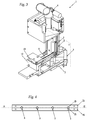
Figures 1-3 show, in section along a vertical plane and in an axonometric view, a feed and count station for buckshot for hunting cartridges loaded with lead shot according to the invention; -
Figure 4 shows, in section along a horizontal plane, a detail of the station ofFigure 1 ; -
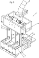
Figure 5 shows, in a partially exploded axonometric view, the station ofFigure 1 . - With reference to the Figures, a feed and
count station 1 forbuckshot 2 for hunting cartridges loaded with lead shot is illustrated for use in loading machines accessorized to receive the empty cartridges, fill them with the necessary internal components, seal them and package them. - Said feed and
count station 1 comprises essentially asupport frame 3; feed means 4 for a plurality ofbuckshot 2 provided with agitator means 14; at least oneslide 5 comprising a duct having a line of longitudinal extension suitable for the canalization of saidbuckshot 2; at least onemovable needle 6 adapted to cooperate with said at least oneslide 5 to select a precise quantity of saidbuckshot 2; download and conveymeans 7 of said precise quantity of saidbuckshot 2 towards said cartridges (not illustrated). - In the embodiment of the invention illustrated in all the Figures, said feed and
count station 1 comprises fourslides 5, arranged parallel to one another on a substantially vertical plane Π passing through the respective longitudinal extension lines of the slides. - Each
slide 5 comprises a duct divided into twoportions - As is particularly evident from the section of
Figure 4 , theportions plates - Said two
portions plates - In the preferred embodiment illustrated, said
portions buckshot 2 having a substantially rhomboidal shape. - Said two
portions first portion 15 of each duct is fixed and asecond portion 25 of said duct is movable. - Said ducts comprise regulating means adapted to regulate and determine the mutual distance between the corresponding two
portions - Said regulating means comprise a plurality of
interchangeable spacers 9, adapted to be inserted between said two grooved planes of saidplates buckshot 2. - The
spacers 9 have a thickness suitable for defining the desired distance between the twoportions buckshot 2, said distance must be modified and consequentlyfurther spacers 9 are used with appropriate thicknesses. - The
plate 35 comprising the grooved plane acting as the fixedportion 15 of theslides 5 shaped as a duct comprises housing pins 11 adapted to retainsaid spacers 9 in a stable position. - To increase the stability and safety of the
entire station 1, the twoplates slides 5 with the respective grooved planes are also secured to each other, once the appropriate distance has been defined, by means of reversible fastening means, forexample screws 8. - As illustrated in the exploded axonometric drawing of
Figure 5 , where thefront plate 45 has been removed, eachspacer 9 is shaped like a ring to fit stably on said housing pins 11, and its thickness is chosen appropriately according to the desired distance to be maintained between the twoportions slides 5, in particular between the two grooved planes belonging to the facingplates - For each
slide 5 shaped as a duct, saidstation 1 comprises aneedle 6, adapted to move reversibly transversally to the slide, being inserted inside it viaappropriate slots 10. - Said
needle 6 is associated with acarriage 12, free to move horizontally to allow insertion of theneedle 6 into theslot 10 of thecorresponding slide 5. Thecarriage 12 can also be positioned along the longitudinal extension direction of the slide. - Said
carriage 12 cooperates withappropriate gauges 13 adapted to define the position of said needle 6: said position is chosen according to the desired number ofbuckshot 2 to be isolated and sent to each cartridge. - By varying the thickness of said
gauges 13, the position of thecarriage 12 to which theneedle 6 is secured is raised or lowered. - Operation of the feed and
count station 1, and the set-up method thereof at each change of calibre of the infeedbuckshot 2, are as follows. - Firstly, the operator chooses a plurality of
spacers 9, evaluating their thicknesses according to the calibre of thebuckshot 2 to be counted and sent to the cartridges, and positions them on the appropriate housing pins 11 obtained on theplate 35 defining thefixed portions 15 of the ducts of theslides 5. - Once the
spacers 9 have been positioned, the operator applies themovable plate 45, comprising its grooved plane, until it stops against thespacers 9, and stably fastens the twoplates screws 8. - The
slides 5 are arranged to allow sliding of thebuckshot 2 inside them, without the risk of obstructions or jamming. - Set-up of the feed and count
station 1 requires very limited times, significantly speeding up and simplifying all the set-up operations of the entire loading machine. - The number of
buckshot 2 to be distributed in each single cartridge are counted by means of saidmovable needles 6 which are inserted transversally in theslots 10 of theslides 5, isolating the chosen quantity ofbuckshot 2, stopping and retaining the upper column of buckshot and letting the "counted" buckshot drop towards the download means 7 and the cartridges to be filled. - To vary the quantity of
buckshot 2 to be isolated, said gauges 13 are used adapted to move thecarriage 12 and therefore the work position of theneedles 6 along the axes of theslides 5. - Once the chosen quantity of
buckshot 2 has been isolated, it is sent to the download means 7 and from the latter to the empty cartridges to be filled.
Claims (10)
- A feed and count station (1) for buckshot (2) for hunting cartridges loaded with lead shots comprising:- a support frame (3);- feed means (4) for a plurality of buckshot (2);- at least one slide (5) having a main line of longitudinal extension suitable for the regular canalization of said buckshot (2);- at least one movable needle (6) adapted to cooperate with said at least one slide (5), reversibly engaging a through hole in a wall of said slide (5), to select a precise quantity of said buckshot (2);- download and convey means (7) of said precise quantity of said buckshot (2) towards said cartridges,at least one slide comprises a duct divided into two portions (15, 25) along a plane (Π) passing through said line of longitudinal extension and comprises regulating means (8, 9) adapted to regulate the mutual distance between said two portions (15, 25).
- The feed and count station (1) according to claim 1, characterized in that said two portions (15, 25) of said duct have a plurality of flat faces.
- The feed and count station (1) according to claim 2, characterized in that each of said two portions (15, 25) of said duct has a V-shaped cross section.
- The feed and count station (1) according to claim 3, characterized in that said two portions (15, 25) of said duct define, in section, a passage area having rhomboidal shape.
- The feed and count station (1) according to claim 1, characterized in that a first portion (15) of said duct is fixed and a second portion (25) of said duct is movable.
- The feed and count station (1) according to claim 5, characterized in that said regulating means comprise screws (8) for stably fastening said movable portion (25) to said fixed portion (15).
- The feed and count station (1) according to claim 1, characterized in that said regulating means comprise a plurality of spacers (9), which are interchangeable according to the dimension of said buckshot (2), adapted to be inserted between one portion and the other portion (15, 25) of said duct.
- The feed and count station (1) according to claim 1, characterized in that it comprises a plurality of slides (5) arranged parallel to one another along said plane (Π) having a substantially vertical arrangement.
- The feed and count station (1) according to claim 8, characterized in that it comprises two plates faces (35, 45) facing each other, provided with V-shaped grooves, adapted to define the two portions (15, 25) of the duct of each slide.
- A loading machine for hunting cartridges characterized in that it comprises a feed and count station (1) for buckshot (2) according to at least one of the preceding claims.
Applications Claiming Priority (1)
| Application Number | Priority Date | Filing Date | Title |
|---|---|---|---|
| ITCR20140021 | 2014-09-19 |
Publications (2)
| Publication Number | Publication Date |
|---|---|
| EP2998908A1 EP2998908A1 (en) | 2016-03-23 |
| EP2998908B1 true EP2998908B1 (en) | 2017-04-12 |
Family
ID=51951869
Family Applications (1)
| Application Number | Title | Priority Date | Filing Date |
|---|---|---|---|
| EP15185606.9A Not-in-force EP2998908B1 (en) | 2014-09-19 | 2015-09-17 | Feed and count station for buckshot for hunting cartridges loaded with lead shots |
Country Status (1)
| Country | Link |
|---|---|
| EP (1) | EP2998908B1 (en) |
Family Cites Families (1)
| Publication number | Priority date | Publication date | Assignee | Title |
|---|---|---|---|---|
| GB190723226A (en) * | 1907-10-21 | 1908-10-21 | William Edward Lake | Machine for Loading Hunting Cartridges. |
-
2015
- 2015-09-17 EP EP15185606.9A patent/EP2998908B1/en not_active Not-in-force
Non-Patent Citations (1)
| Title |
|---|
| None * |
Also Published As
| Publication number | Publication date |
|---|---|
| EP2998908A1 (en) | 2016-03-23 |
Similar Documents
| Publication | Publication Date | Title |
|---|---|---|
| JP6364497B2 (en) | Bending machine for sheet metal | |
| EP3153248B1 (en) | Drawing and/or straightening unit for oblong metal products, such as bars, round pieces or metal wire | |
| EP2489486B1 (en) | Apparatus for cutting paper logs in a plurality of rolls | |
| EP3377845B1 (en) | Loading machine for cartridges with a metal case | |
| WO2012110136A1 (en) | Cutting machine with increased productivity for manufacturing wire-like rods, particularly for the production of rod-like electrodes for welding | |
| CN105398810A (en) | Release blocking mechanism for automobile brake caliper support | |
| EP2998908A1 (en) | Feed and count station for buckshot for hunting cartridges loaded with lead shots | |
| CN110422601A (en) | Accurate directional feeder | |
| EP2827092B1 (en) | Cartridge loading machine with quick caliber change system | |
| KR20180018476A (en) | Method for performing precise laser cutting on a ribbon sheet and apparatus for carrying out the method | |
| EP3072603B1 (en) | Finishing section of a machine for producing square pipes | |
| EP3541557B1 (en) | Tapping machine for screw threading of perforated products provided with a centring device | |
| CN103009171B (en) | A kind of feed appliance of full-automatic numerical control eye glass frame processing machine | |
| EP2524743A1 (en) | Blanking die with device for replacing at least one punch | |
| CN103920828A (en) | Automatic lamp base separating device | |
| KR101481763B1 (en) | manufacturing device for motor core and manufacturing method the motor core | |
| EP3147228B1 (en) | Apparatus for forming groups of products on edge | |
| KR101424227B1 (en) | Pinnacle mold assembly | |
| CN110681862A (en) | Forming die for internal gear powder metallurgy | |
| JP2021094595A (en) | Multiple shape cutting blanking die device | |
| CN107457453A (en) | A kind of blanking, pushing positioner and the beveler using the device | |
| JP2012183782A (en) | Bead automatic feeding apparatus, and right and left sorting apparatus of bead spacer | |
| EP3050440A1 (en) | A filling system for a machine for filling trays and a method for filling trays | |
| KR101524863B1 (en) | Screw forming device for iron bar | |
| KR20170001992A (en) | Automatic allignment apparatus for mold materials |
Legal Events
| Date | Code | Title | Description |
|---|---|---|---|
| PUAI | Public reference made under article 153(3) epc to a published international application that has entered the european phase |
Free format text: ORIGINAL CODE: 0009012 |
|
| AK | Designated contracting states |
Kind code of ref document: A1 Designated state(s): AL AT BE BG CH CY CZ DE DK EE ES FI FR GB GR HR HU IE IS IT LI LT LU LV MC MK MT NL NO PL PT RO RS SE SI SK SM TR |
|
| AX | Request for extension of the european patent |
Extension state: BA ME |
|
| 17P | Request for examination filed |
Effective date: 20160919 |
|
| RBV | Designated contracting states (corrected) |
Designated state(s): AL AT BE BG CH CY CZ DE DK EE ES FI FR GB GR HR HU IE IS IT LI LT LU LV MC MK MT NL NO PL PT RO RS SE SI SK SM TR |
|
| GRAP | Despatch of communication of intention to grant a patent |
Free format text: ORIGINAL CODE: EPIDOSNIGR1 |
|
| INTG | Intention to grant announced |
Effective date: 20161109 |
|
| GRAS | Grant fee paid |
Free format text: ORIGINAL CODE: EPIDOSNIGR3 |
|
| GRAA | (expected) grant |
Free format text: ORIGINAL CODE: 0009210 |
|
| AK | Designated contracting states |
Kind code of ref document: B1 Designated state(s): AL AT BE BG CH CY CZ DE DK EE ES FI FR GB GR HR HU IE IS IT LI LT LU LV MC MK MT NL NO PL PT RO RS SE SI SK SM TR |
|
| REG | Reference to a national code |
Ref country code: GB Ref legal event code: FG4D |
|
| REG | Reference to a national code |
Ref country code: CH Ref legal event code: EP |
|
| REG | Reference to a national code |
Ref country code: IE Ref legal event code: FG4D |
|
| REG | Reference to a national code |
Ref country code: AT Ref legal event code: REF Ref document number: 884573 Country of ref document: AT Kind code of ref document: T Effective date: 20170515 |
|
| REG | Reference to a national code |
Ref country code: DE Ref legal event code: R096 Ref document number: 602015002228 Country of ref document: DE |
|
| REG | Reference to a national code |
Ref country code: NL Ref legal event code: MP Effective date: 20170412 |
|
| REG | Reference to a national code |
Ref country code: LT Ref legal event code: MG4D |
|
| REG | Reference to a national code |
Ref country code: AT Ref legal event code: MK05 Ref document number: 884573 Country of ref document: AT Kind code of ref document: T Effective date: 20170412 |
|
| PG25 | Lapsed in a contracting state [announced via postgrant information from national office to epo] |
Ref country code: NL Free format text: LAPSE BECAUSE OF FAILURE TO SUBMIT A TRANSLATION OF THE DESCRIPTION OR TO PAY THE FEE WITHIN THE PRESCRIBED TIME-LIMIT Effective date: 20170412 |
|
| PG25 | Lapsed in a contracting state [announced via postgrant information from national office to epo] |
Ref country code: FI Free format text: LAPSE BECAUSE OF FAILURE TO SUBMIT A TRANSLATION OF THE DESCRIPTION OR TO PAY THE FEE WITHIN THE PRESCRIBED TIME-LIMIT Effective date: 20170412 Ref country code: GR Free format text: LAPSE BECAUSE OF FAILURE TO SUBMIT A TRANSLATION OF THE DESCRIPTION OR TO PAY THE FEE WITHIN THE PRESCRIBED TIME-LIMIT Effective date: 20170713 Ref country code: HR Free format text: LAPSE BECAUSE OF FAILURE TO SUBMIT A TRANSLATION OF THE DESCRIPTION OR TO PAY THE FEE WITHIN THE PRESCRIBED TIME-LIMIT Effective date: 20170412 Ref country code: NO Free format text: LAPSE BECAUSE OF FAILURE TO SUBMIT A TRANSLATION OF THE DESCRIPTION OR TO PAY THE FEE WITHIN THE PRESCRIBED TIME-LIMIT Effective date: 20170712 Ref country code: LT Free format text: LAPSE BECAUSE OF FAILURE TO SUBMIT A TRANSLATION OF THE DESCRIPTION OR TO PAY THE FEE WITHIN THE PRESCRIBED TIME-LIMIT Effective date: 20170412 Ref country code: ES Free format text: LAPSE BECAUSE OF FAILURE TO SUBMIT A TRANSLATION OF THE DESCRIPTION OR TO PAY THE FEE WITHIN THE PRESCRIBED TIME-LIMIT Effective date: 20170412 Ref country code: AT Free format text: LAPSE BECAUSE OF FAILURE TO SUBMIT A TRANSLATION OF THE DESCRIPTION OR TO PAY THE FEE WITHIN THE PRESCRIBED TIME-LIMIT Effective date: 20170412 |
|
| PG25 | Lapsed in a contracting state [announced via postgrant information from national office to epo] |
Ref country code: SE Free format text: LAPSE BECAUSE OF FAILURE TO SUBMIT A TRANSLATION OF THE DESCRIPTION OR TO PAY THE FEE WITHIN THE PRESCRIBED TIME-LIMIT Effective date: 20170412 Ref country code: LV Free format text: LAPSE BECAUSE OF FAILURE TO SUBMIT A TRANSLATION OF THE DESCRIPTION OR TO PAY THE FEE WITHIN THE PRESCRIBED TIME-LIMIT Effective date: 20170412 Ref country code: BG Free format text: LAPSE BECAUSE OF FAILURE TO SUBMIT A TRANSLATION OF THE DESCRIPTION OR TO PAY THE FEE WITHIN THE PRESCRIBED TIME-LIMIT Effective date: 20170712 Ref country code: RS Free format text: LAPSE BECAUSE OF FAILURE TO SUBMIT A TRANSLATION OF THE DESCRIPTION OR TO PAY THE FEE WITHIN THE PRESCRIBED TIME-LIMIT Effective date: 20170412 Ref country code: IS Free format text: LAPSE BECAUSE OF FAILURE TO SUBMIT A TRANSLATION OF THE DESCRIPTION OR TO PAY THE FEE WITHIN THE PRESCRIBED TIME-LIMIT Effective date: 20170812 Ref country code: PL Free format text: LAPSE BECAUSE OF FAILURE TO SUBMIT A TRANSLATION OF THE DESCRIPTION OR TO PAY THE FEE WITHIN THE PRESCRIBED TIME-LIMIT Effective date: 20170412 |
|
| REG | Reference to a national code |
Ref country code: DE Ref legal event code: R097 Ref document number: 602015002228 Country of ref document: DE |
|
| PG25 | Lapsed in a contracting state [announced via postgrant information from national office to epo] |
Ref country code: DK Free format text: LAPSE BECAUSE OF FAILURE TO SUBMIT A TRANSLATION OF THE DESCRIPTION OR TO PAY THE FEE WITHIN THE PRESCRIBED TIME-LIMIT Effective date: 20170412 Ref country code: EE Free format text: LAPSE BECAUSE OF FAILURE TO SUBMIT A TRANSLATION OF THE DESCRIPTION OR TO PAY THE FEE WITHIN THE PRESCRIBED TIME-LIMIT Effective date: 20170412 Ref country code: SK Free format text: LAPSE BECAUSE OF FAILURE TO SUBMIT A TRANSLATION OF THE DESCRIPTION OR TO PAY THE FEE WITHIN THE PRESCRIBED TIME-LIMIT Effective date: 20170412 Ref country code: RO Free format text: LAPSE BECAUSE OF FAILURE TO SUBMIT A TRANSLATION OF THE DESCRIPTION OR TO PAY THE FEE WITHIN THE PRESCRIBED TIME-LIMIT Effective date: 20170412 Ref country code: CZ Free format text: LAPSE BECAUSE OF FAILURE TO SUBMIT A TRANSLATION OF THE DESCRIPTION OR TO PAY THE FEE WITHIN THE PRESCRIBED TIME-LIMIT Effective date: 20170412 |
|
| PLBE | No opposition filed within time limit |
Free format text: ORIGINAL CODE: 0009261 |
|
| STAA | Information on the status of an ep patent application or granted ep patent |
Free format text: STATUS: NO OPPOSITION FILED WITHIN TIME LIMIT |
|
| PG25 | Lapsed in a contracting state [announced via postgrant information from national office to epo] |
Ref country code: IT Free format text: LAPSE BECAUSE OF FAILURE TO SUBMIT A TRANSLATION OF THE DESCRIPTION OR TO PAY THE FEE WITHIN THE PRESCRIBED TIME-LIMIT Effective date: 20170412 Ref country code: SM Free format text: LAPSE BECAUSE OF FAILURE TO SUBMIT A TRANSLATION OF THE DESCRIPTION OR TO PAY THE FEE WITHIN THE PRESCRIBED TIME-LIMIT Effective date: 20170412 |
|
| 26N | No opposition filed |
Effective date: 20180115 |
|
| REG | Reference to a national code |
Ref country code: DE Ref legal event code: R119 Ref document number: 602015002228 Country of ref document: DE |
|
| PG25 | Lapsed in a contracting state [announced via postgrant information from national office to epo] |
Ref country code: SI Free format text: LAPSE BECAUSE OF FAILURE TO SUBMIT A TRANSLATION OF THE DESCRIPTION OR TO PAY THE FEE WITHIN THE PRESCRIBED TIME-LIMIT Effective date: 20170412 Ref country code: MC Free format text: LAPSE BECAUSE OF FAILURE TO SUBMIT A TRANSLATION OF THE DESCRIPTION OR TO PAY THE FEE WITHIN THE PRESCRIBED TIME-LIMIT Effective date: 20170412 |
|
| REG | Reference to a national code |
Ref country code: IE Ref legal event code: MM4A |
|
| PG25 | Lapsed in a contracting state [announced via postgrant information from national office to epo] |
Ref country code: LU Free format text: LAPSE BECAUSE OF NON-PAYMENT OF DUE FEES Effective date: 20170917 |
|
| REG | Reference to a national code |
Ref country code: FR Ref legal event code: ST Effective date: 20180531 |
|
| PG25 | Lapsed in a contracting state [announced via postgrant information from national office to epo] |
Ref country code: IE Free format text: LAPSE BECAUSE OF NON-PAYMENT OF DUE FEES Effective date: 20170917 Ref country code: DE Free format text: LAPSE BECAUSE OF NON-PAYMENT OF DUE FEES Effective date: 20180404 |
|
| PG25 | Lapsed in a contracting state [announced via postgrant information from national office to epo] |
Ref country code: FR Free format text: LAPSE BECAUSE OF NON-PAYMENT OF DUE FEES Effective date: 20171002 |
|
| PG25 | Lapsed in a contracting state [announced via postgrant information from national office to epo] |
Ref country code: MT Free format text: LAPSE BECAUSE OF NON-PAYMENT OF DUE FEES Effective date: 20170917 |
|
| PGFP | Annual fee paid to national office [announced via postgrant information from national office to epo] |
Ref country code: TR Payment date: 20180913 Year of fee payment: 4 |
|
| PGFP | Annual fee paid to national office [announced via postgrant information from national office to epo] |
Ref country code: BE Payment date: 20180927 Year of fee payment: 4 |
|
| REG | Reference to a national code |
Ref country code: CH Ref legal event code: PL |
|
| PG25 | Lapsed in a contracting state [announced via postgrant information from national office to epo] |
Ref country code: HU Free format text: LAPSE BECAUSE OF FAILURE TO SUBMIT A TRANSLATION OF THE DESCRIPTION OR TO PAY THE FEE WITHIN THE PRESCRIBED TIME-LIMIT; INVALID AB INITIO Effective date: 20150917 |
|
| PG25 | Lapsed in a contracting state [announced via postgrant information from national office to epo] |
Ref country code: CH Free format text: LAPSE BECAUSE OF NON-PAYMENT OF DUE FEES Effective date: 20180930 Ref country code: LI Free format text: LAPSE BECAUSE OF NON-PAYMENT OF DUE FEES Effective date: 20180930 |
|
| PG25 | Lapsed in a contracting state [announced via postgrant information from national office to epo] |
Ref country code: CY Free format text: LAPSE BECAUSE OF FAILURE TO SUBMIT A TRANSLATION OF THE DESCRIPTION OR TO PAY THE FEE WITHIN THE PRESCRIBED TIME-LIMIT Effective date: 20170412 |
|
| PG25 | Lapsed in a contracting state [announced via postgrant information from national office to epo] |
Ref country code: MK Free format text: LAPSE BECAUSE OF FAILURE TO SUBMIT A TRANSLATION OF THE DESCRIPTION OR TO PAY THE FEE WITHIN THE PRESCRIBED TIME-LIMIT Effective date: 20170412 |
|
| PG25 | Lapsed in a contracting state [announced via postgrant information from national office to epo] |
Ref country code: PT Free format text: LAPSE BECAUSE OF FAILURE TO SUBMIT A TRANSLATION OF THE DESCRIPTION OR TO PAY THE FEE WITHIN THE PRESCRIBED TIME-LIMIT Effective date: 20170412 |
|
| PG25 | Lapsed in a contracting state [announced via postgrant information from national office to epo] |
Ref country code: AL Free format text: LAPSE BECAUSE OF FAILURE TO SUBMIT A TRANSLATION OF THE DESCRIPTION OR TO PAY THE FEE WITHIN THE PRESCRIBED TIME-LIMIT Effective date: 20170412 |
|
| REG | Reference to a national code |
Ref country code: BE Ref legal event code: MM Effective date: 20190930 |
|
| PG25 | Lapsed in a contracting state [announced via postgrant information from national office to epo] |
Ref country code: BE Free format text: LAPSE BECAUSE OF NON-PAYMENT OF DUE FEES Effective date: 20190930 |
|
| GBPC | Gb: european patent ceased through non-payment of renewal fee |
Effective date: 20190917 |
|
| PG25 | Lapsed in a contracting state [announced via postgrant information from national office to epo] |
Ref country code: GB Free format text: LAPSE BECAUSE OF NON-PAYMENT OF DUE FEES Effective date: 20190917 |
|
| PG25 | Lapsed in a contracting state [announced via postgrant information from national office to epo] |
Ref country code: TR Free format text: LAPSE BECAUSE OF NON-PAYMENT OF DUE FEES Effective date: 20190917 |