EP2998798A1 - Cover opening/closing device and image forming apparatus including this - Google Patents
Cover opening/closing device and image forming apparatus including this Download PDFInfo
- Publication number
- EP2998798A1 EP2998798A1 EP15184983.3A EP15184983A EP2998798A1 EP 2998798 A1 EP2998798 A1 EP 2998798A1 EP 15184983 A EP15184983 A EP 15184983A EP 2998798 A1 EP2998798 A1 EP 2998798A1
- Authority
- EP
- European Patent Office
- Prior art keywords
- button
- cover
- lock
- lock member
- closing device
- Prior art date
- Legal status (The legal status is an assumption and is not a legal conclusion. Google has not performed a legal analysis and makes no representation as to the accuracy of the status listed.)
- Granted
Links
Images





Classifications
-
- E—FIXED CONSTRUCTIONS
- E05—LOCKS; KEYS; WINDOW OR DOOR FITTINGS; SAFES
- E05B—LOCKS; ACCESSORIES THEREFOR; HANDCUFFS
- E05B65/00—Locks or fastenings for special use
- E05B65/006—Locks or fastenings for special use for covers or panels
-
- G—PHYSICS
- G03—PHOTOGRAPHY; CINEMATOGRAPHY; ANALOGOUS TECHNIQUES USING WAVES OTHER THAN OPTICAL WAVES; ELECTROGRAPHY; HOLOGRAPHY
- G03G—ELECTROGRAPHY; ELECTROPHOTOGRAPHY; MAGNETOGRAPHY
- G03G21/00—Arrangements not provided for by groups G03G13/00 - G03G19/00, e.g. cleaning, elimination of residual charge
- G03G21/16—Mechanical means for facilitating the maintenance of the apparatus, e.g. modular arrangements
- G03G21/1604—Arrangement or disposition of the entire apparatus
- G03G21/1623—Means to access the interior of the apparatus
-
- G—PHYSICS
- G03—PHOTOGRAPHY; CINEMATOGRAPHY; ANALOGOUS TECHNIQUES USING WAVES OTHER THAN OPTICAL WAVES; ELECTROGRAPHY; HOLOGRAPHY
- G03G—ELECTROGRAPHY; ELECTROPHOTOGRAPHY; MAGNETOGRAPHY
- G03G21/00—Arrangements not provided for by groups G03G13/00 - G03G19/00, e.g. cleaning, elimination of residual charge
- G03G21/16—Mechanical means for facilitating the maintenance of the apparatus, e.g. modular arrangements
- G03G21/1604—Arrangement or disposition of the entire apparatus
- G03G21/1623—Means to access the interior of the apparatus
- G03G21/1633—Means to access the interior of the apparatus using doors or covers
-
- G—PHYSICS
- G03—PHOTOGRAPHY; CINEMATOGRAPHY; ANALOGOUS TECHNIQUES USING WAVES OTHER THAN OPTICAL WAVES; ELECTROGRAPHY; HOLOGRAPHY
- G03G—ELECTROGRAPHY; ELECTROPHOTOGRAPHY; MAGNETOGRAPHY
- G03G2221/00—Processes not provided for by group G03G2215/00, e.g. cleaning or residual charge elimination
- G03G2221/16—Mechanical means for facilitating the maintenance of the apparatus, e.g. modular arrangements and complete machine concepts
- G03G2221/1651—Mechanical means for facilitating the maintenance of the apparatus, e.g. modular arrangements and complete machine concepts for connecting the different parts
- G03G2221/1654—Locks and means for positioning or alignment
-
- G—PHYSICS
- G03—PHOTOGRAPHY; CINEMATOGRAPHY; ANALOGOUS TECHNIQUES USING WAVES OTHER THAN OPTICAL WAVES; ELECTROGRAPHY; HOLOGRAPHY
- G03G—ELECTROGRAPHY; ELECTROPHOTOGRAPHY; MAGNETOGRAPHY
- G03G2221/00—Processes not provided for by group G03G2215/00, e.g. cleaning or residual charge elimination
- G03G2221/16—Mechanical means for facilitating the maintenance of the apparatus, e.g. modular arrangements and complete machine concepts
- G03G2221/1678—Frame structures
- G03G2221/169—Structural door designs
Definitions
- the present disclosure relates to a cover opening/closing device open and close a cover turnably supported by an apparatus body and to an image forming apparatus including this.
- Some apparatus body (housing) of an electronic device such as an image forming apparatus is provided with a cover opened/closed in replacing a consumable component and in implementing various maintenances.
- a cover opening/closing mechanism including a button movable linearly in a vertical direction with respect to an appearance surface of a cover, a lock member sliding in a direction in parallel with the appearance surface in linkage with the linear movement of the button, a first compression spring returning the button to its initial position, and a second compression spring compressed between the lock member and the cover.
- the lock member is biased in a direction of being locked by an engage part of the apparatus body by the second compression spring.
- This cover opening/closing mechanism is configured such that the lock member slides and is unlocked by resisting against a bias force of the first compression spring when the button is depressed by resisting against the bias force of the first compression spring.
- the abovementioned cover opening/closing mechanism is required to dispose the second compression spring to bias the lock member toward the engage part, incurring enlargement and complication of the mechanism. Due to that, the abovementioned cover opening/closing mechanism has a problem that it cannot be adopted for an electronic device which is required to be downsized.
- a cover opening/closing device includes an engage mechanism and a lock mechanism.
- the engage mechanism is provided in either one of the apparatus body and a cover turning centering a turning shaft with respect to the apparatus body.
- the lock mechanism is provided in either other one of the apparatus body and the cover.
- the lock member includes a button, a lock member, and an interlocking mechanism.
- the button is provided to be able to move linearly in a normal line direction of an appearance surface of either other one of the apparatus body and the cover.
- the lock member is provided to be able to move linearly in a direction in parallel with the appearance surface between a lock position where the lock member is engagable with the engage mechanism and an unlock position where the lock member is disengaged.
- the interlocking mechanism interlocks a movement of the button with a movement of the lock member.
- the interlocking mechanism includes a return member, an oblique groove, and a projection part. The return member returns the button to an initial position.
- the oblique groove is provided at either one of the button and the lock member and extends obliquely with respect to the normal line of the appearance surface.
- the projection part is provided in either other one of the button and the lock member and fits movably along the oblique groove.
- the oblique groove guides a relative movement of the projection part so as to interlock a pressing operation of the button located at the initial position with a movement of the lock member heading to the unlock position and guides a relative movement of the projection part so as to interlock a return operation of the button caused by the return member with a movement of the lock member heading to the lock position.
- an image forming apparatus includes an image forming part performing an image forming process; and a cover opening/closing device.
- FIG. 1 is a perspective view illustrating the color printer 1
- FIG. 2 is a perspective view illustrating a state in which a cover 6 of the color printer 1 is opened. It is noted that directions are indicated appropriately in each drawing in the following description.
- the color printer 1 includes an apparatus body 2, a sheet feed cassette 3 and a discharge tray 4.
- the apparatus body 2 is formed substantially into a shape of a rectangular box.
- the sheet feed cassette 3 is provided at a lower part of the apparatus body 2.
- the discharge tray 4 is provided on an upper surface of the apparatus body 2.
- a container replacing opening 2a formed into a rectangular shape in side view is provided on a right side surface of the apparatus body 2.
- Arrayed in a front-rear direction within the container replacing opening 2a are four toner containers 5a.
- the four toner containers 5a contain four color toners (developer), respectively.
- an image forming part 5b including the four toner containers 5a.
- the image forming part 5b performs an image forming process by means of a known electro-photographic system by using the four color toners onto a sheet (not shown) conveyed from the sheet feed cassette 3 through a conveying path (not shown).
- the sheet on which an image has been formed is conveyed further downstream of the conveying path and is discharged out of the apparatus body 2 to the discharge tray 4.
- a cover 6 for opening and closing the container replacing opening 2a is provided on the right side surface of the apparatus body 2.
- the cover 6 is formed into a rectangular plate by a synthetic resin for example.
- the cover 6 is configured to turn substantially horizontally centering on a pair of upper and lower turning shafts 10.
- the cover 6 constitutes a right side surface of the apparatus body 2 as it closes the container replacing opening 2a (see FIG. 1 ). That is, an outer surface 11 of the cover 6 is substantially flush with an outer surface 2b of the apparatus body 2 composing an outer peripheral edge part of the container replacing opening 2a.
- the respective toner conta iners 5a are exposed by opening the cover 6 of the container replacing opening 2a (see FIG. 2 ). That is, the respective toner containers 5a can be replaced by opening the cover 6.
- the apparatus body 2 and the cover 6 are provided with a cover opening/closing device 7.
- the cover opening/closing device 7 is provided to conduct opening and closing operations of the cover 6.
- FIG. 3 is a perspective view illustrating an engage mechanism 20 of the cover opening/closing device 7.
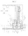
- FIG. 4 is a section view taken along a line IV-IV in FIG. 1 .
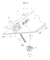
- FIG. 5 is a perspective view illustrating a lock mechanism 30 of the cover opening/closing device 7.
- FIG. 6 is an exploded perspective view illustrating the lock mechanism 30 of the cover opening/closing device 7.
- FIG. 7 is a section view taken along a line VII-VII in FIG. 1 .
- FIG. 8 is a section view illustrating a state in which a button 32 in FIG. 7 is depressed. It is noted that the respective directions are set based on a state in which the cover 6 is closed for convenience of the following description.
- the cover opening/closing device 7 includes the engage mechanism 20 and the lock mechanism 30.
- the engage mechanism 20 is disposed substantially at middle in a vertical direction of a right front part of the apparatus body 2.
- the lock mechanism 30 is disposed substantially at middle in the vertical direction of a front part of the cover 6.
- the engage mechanism 20 includes an engage part 21, a fitting concave part 22 and an extrusion spring 23.
- the engage part 21 is dented on an inner surface of a front edge part of the apparatus body 2 forming a container replacing opening 2a.
- a catching surface 24 inclined forward from the engage part 21 toward the right side (outer side) is formed on the front edge part of the apparatus body 2.
- the fitting concave part 22 is formed at a position facing the lock mechanism 30 when the cover 6 is closed.
- the fitting concave part 22 is provided with a sensor (not shown) detecting that the cover 6 is closed.
- the extrusion spring 23 i.e., a bias member, is provided in the fitting concave part 22.
- the extrusion spring 23 is a so-called coil spring and is configured to elastically deform in the right-left direction while abutting its one end against a bottom surface of the fitting concave part 22. It is noted that while its detail will be described later, the extrusion spring 23 is configured such that another end thereof is capable of abutting against a part of the lock mechanism 30 fitted into the fitting concave part 22. That is, the extrusion spring 23 is provided to bias the cover 6 in an opening direction through the lock mechanism 30.
- the lock mechanism 30 includes a lock housing 31, a button 32, a lock member 33, and an interlocking mechanism 34.
- the lock housing 31 is provided on a back surface 12 of the cover 6.
- the button 32 and the lock member 33 are held by the lock housing 31.
- the interlocking mechanism 34 is provided in the button 32 and the lock member 33.
- the lock housing 31 includes a frame part 40 and a fitting piece part 41.
- the lock housing 31 is integrally molded on the back surface 12 of the cover 6 by a synthetic resin material for example.
- the frame part 40 is formed substantially into a rectangular cylinder shape having rectangular openings at both upper and lower surfaces thereof.
- the frame part 40 is provided at a peripheral edge part of a rectangular button hole 13 penetrating from the back surface 12 of the cover 6 through the cover 6. That is, an outside of the cover 6 communicates with an inside of the frame part 40 through the button hole 13.
- the frame part 40 has a cylindrical boss part 42 at a left inner surface (inner surface facing the back surface 12).
- the boss part 42 projects from the left inner surface of the frame part 40 toward the back surface 12 side (right side).
- Rectangular slide holes 43 are formed respectively through both front and rear walls of the frame part 40. It is noted the frame part 40 is stepped such that a left side part (part distant from the back surface 12) of the frame part 40 is formed narrowly in the front-rear direction. Therefore, inner surfaces of a pair of front and rear stepped parts are formed to be guide faces 44 flush with the left edge part of the respective slide holes 43 (see FIG. 4 ).
- the fitting piece part 41 is formed substantially into a plate which is thin in the front-rear direction.
- the fitting piece part 41 extends from the front end part of the frame part 40 toward the left side. That is, the fitting piece part 41 extends along a normal line V of an appearance surface 11 of the cover 6 (or the back surface 12).
- the fitting piece part 41 is provided with tapered surfaces 45 formed by chamfering upper and lower corner parts of an edge part of the fitting piece pare 41.
- the button 32 includes a pressing surface part 50 and a pair of upper and lower extension parts 51.
- the button 32 is integrally molded by a synthetic resin material for example.
- the pressing surface part 50 is formed into a rectangular plate when viewed from a side.
- the pressing surface part 50 is formed into a shape and size capable of fitting into the button hole 13.
- a cylindrical button-side boss part 52 extending toward the left side is provided substantially at center of a back surface of the pressing surface part 50.
- the pair of upper and lower extension parts 51 extends toward the left side from both upper and lower ends of the pressing surface part 50. That is, the button 32 is formed substantially into a shape of letter U in a front view.
- the respective extension parts 51 are formed substantially into a triangular shape in a front view.
- the button 32 penetrates through the button hole 13 from the appearance surface 11 side of the cover 6 and is held within the frame part 40 of the lock housing 31. As shown in FIGs. 7 and 8 , the button 32 is provided so as to be able to move linearly in the normal line direction of the appearance surface 11 of the cover 6 between an initial position P1 and a depressed position P2. When the button 32 is located at the initial position P1, the pressing surface part 50 is disposed within the button hole 13 and is substantially in flush with the appearance surface 11 of the cover 6 (see FIG. 7 ). If the pressing surface part 50 is depressed, the button 32 moves linearly from the initial position P1 to the depressed position P2 (see FIG. 8 ).
- the lock member 33 includes a frame-like part 53 and a claw part 54.
- the lock member 33 is integrally molded by a synthetic resin material for example.
- the frame-like part 53 is formed substantially into a rectangular cylinder shape having a through opening 55 at center thereof (see FIG. 6 ).
- the claw part 54 projects toward the front side from a front end surface of the frame-like part 53.
- the claw part 54 is disposed on the right side (outer side) of the front end surface of the frame-like part 53 and has a step between the front end surface of the frame-like part 53.
- An inclined surface 56 is formed by chamfering a left corner part of an edge part of the claw part 54.
- the lock member 33 penetrates through a pair of front and rear slide holes 43 opened through the frame part 40 and is held within the frame part 40. As shown in FIGs. 7 and 8 , the lock member 33 is provided so as to be able to move linearly in a direction in parallel with the appearance surface 11 between a lock position L1 where the lock member 33 is engageable with the engage mechanism 20 (engage part 21) and an unlock position L2 where the lock member 33 is disengaged from the engage part 21.
- the interlocking mechanism 34 includes a return spring 60, a pair of upper and lower oblique grooves 61 and a pair of upper and lower projection parts 62.
- the interlocking mechanism 34 is configured so as to interlock a movement of the lock member 33 with a movement of the button 32.
- the return spring 60 i.e., a return member, is a so-called coil spring and is disposed between the lock housing 31 and the button 32.
- One end part of the return spring 60 fits into the boss part 42 of the frame part 40 and another end part of the return spring 60 fits into a button-side boss part 52 of the pressing surface part 50.
- the return spring 60 exerts a bias force (return force) on the button 32 such that the button 32 returns to the initial position P1.
- the extrusion spring 23 described above has a bias force greater than the bias force (return force) of the return member.
- each oblique groove 61 is provided through the pair of upper and lower extension parts 51 of the button 32.
- Each oblique groove 61 is formed so as to penetrate through the extension part 51 in the vertical direction.
- each oblique groove 61 extends aslant with respect to the normal line V of the appearance surface 11.
- each oblique groove 61 is formed so as to incline forward from the right side (outer side) to the left side (inner side). More specifically, each oblique groove 61 is inclined by about 30 degrees with respect to the normal line V (60 degree with respect to the appearance surface 11 of the cover 6).
- each projection part 62 is provided so as to project from both upper and lower surfaces of the lock member 33.
- Each projection part 62 is formed into a columnar shape having a tapered part 63 at a projecting edge part thereof (see FIG. 6 ).
- Each projection part 62 is provided projectively so as to fit movably along the oblique groove 61.
- an operator penetrates the lock member 33 through the pair of front and rear slide holes 43 to hold the lock member 33 by the frame part 40.
- the operator puts the return spring 60 through the button hole 13 of the cover 6 and through the through opening 55 of the lock member 33 and fits one end part of the return spring 60 around the boss part 42 of the frame part 40. It is noted that the other end part of the return spring 60 extends outside through the button hole 13.
- the operator fits the other end part of the return spring 60 around the button-side boss part 52 of the button 32. While compressing the return spring 60, the operator advances the button 32 into the frame part 40 through the button hole 13. Then, the pair of upper and lower extension parts 51 of the button 32 abuts against the respective projection parts 62 provided projectively in the lock member 33. When the button 32 is advanced further, the pair of upper and lower extension parts 51 come into slidable contact with the tapered parts 63 of the respective projection parts 62 and elastically deform so as to extend in the vertical direction.
- the button 32 is biased to the initial position P1 by the return spring 60 in the state in which the cover 6 is closed.
- Each projection part 62 provided projectively in the lock member 33 is held by the left end part (inner side) of the oblique groove 61 by the bias force (return force) of the return spring 60.
- the claw part 54 of the lock member 33 enters and engages with the engage part 21 of the engage mechanism 20. That is, the lock member 33 is held at the lock position L1 by the bias force of the return spring 60.
- the lock housing 31 of the lock mechanism 30 fits in the fitting concave part 22 of the engage mechanism 20.
- the extrusion spring 23 of the engage mechanism 20 is compressed by the fitting piece part 41 of the lock housing 31. It is noted that another end part of the extrusion spring 23 abuts against the edge surface of the fitting piece part 41.
- the closed condition is kept because the claw part 54 is engaged with the engage part 21. That is, the cover 6 is locked.
- the upper tapered surface 45 of the fitting piece part 41 actuates a sensor. This arrangement makes it possible for a control unit (not shown) connected with the sensor to detect the closure of the cover 6.
- each projection part 62 moves relatively obliquely right rearward by being guided by the oblique groove 61 and arrives at the right end part (outer side) of the oblique groove 61.
- each projection part 62 moves rearward by a front and rear difference D of the both right and left parts of the oblique groove 61.
- the lock member 33 in which each projection part 62 is projectively provided also moves rearward by being guided by each slide hole 43 and each guide surface 44 and disengages the claw part 54 from the engage part 21. That is, a state in which the lock member 33 moves to the unlock position L2 is brought about.
- the extrusion spring 23 presses the cover 6 in the opening direction before the return spring 60 returns the button 32 to the initial position P1, because the extrusion spring 23 on the apparatus body 2 side has the bias force stronger that the bias force (return force) of the return spring 60 that returns the button 32.
- This arrangement makes it possible to smoothly carry out the opening operation of the cover 6 even if the cover 6 is lightly pressed through the button 32.
- the cover 6 turns centering on the respective turning shafts 10 and is opened (see FIG. 2 ).
- each projection part 62 moves relatively obliquely left forward by being guided by the oblique groove 61 and arrives at the left end part of the oblique groove 61. Accordingly, the lock member 33 in which each projection part 62 is projectively provided also moves forward by the front and rear difference D. That is, the state in which the lock member 33 has moved to the lock position L1 is brought about.
- the lock position L1 refers not only the position where the lock member 33 (the claw part 54) is actually engaged with the engage part 21, but also a position where the lock member 33 is engaged with the engage part 21 when the cover 6 is closed even if it is a state in which the lock member 33 is disengaged.
- each oblique groove 61 guides the relative movement of each projection part 62 so as to interlock the depressing operation of the button 32 located at the initial position P1 with the movement of the lock member 33 heading toward the unlock position L2.
- each oblique groove 61 guides the relative movement of each projection part 62 so as to interlock the button returning operation by the return spring 60 with the movement of the lock member 33 heading toward the lock position L1.
- each projection part 62 projectively provided moves relatively along the oblique groove 61. That is, the button 32 moves in the depressing direction from the initial position P1 by resisting against the bias force of the return spring 60 in linkage with the movement of the lock member 33.
- the button 32 returns to the initial position P1 by the bias force of the return spring 60. Because each projection part 62 moves relatively along the oblique groove 61 in linkage with this return operation, the lock member 33 moves to the lock position L1. That is, the claw part 54 is engaged with the engage part 21, and the cover 6 is locked.
- the reciprocal movement of the button 32 along the normal line V is converted into the reciprocal movement of the lock member 33 along the appearance surface 11 through each projection part 62 relatively and obliquely moving by being guided by each oblique groove 61.
- the return spring 60 has the functions of returning the button 32 to the initial position P1 and of holding the lock member 33 at the lock position L1.
- This arrangement makes it possible to downsize the cover opening/closing device 7 and to cut a number of components because it is possible to eliminate a dedicated spring and others for holding the lock member 33 at the lock position L1 for example. Still further, it is possible to downsize the color printer 1 by adopting the downsized and simplified cover opening/closing device 7.
- the cover 6 is pushed out in the opening direction by the bias force of the extrusion spring 23 because the lock member 33 is moved to the unlock position L2. This arrangement makes it possible to automatically open the cover 6 by interlocking with the release of the lock.
- each projection part 62 relatively moves smoothly along the oblique groove 61 by setting the angle formed between the appearance surface 11 and each oblique groove 61 at 60 degrees. It is noted that while the angle formed between the appearance surface 11 and each oblique groove 61 is set at 60 degrees in the cover opening/closing device 7 of the present embodiment, the present disclosure is not limited to such angle.
- Each oblique groove 61 may be formed so as to incline with respect the appearance surface 11 within a range of more than 60 degrees and less than 90 degrees.
- the cover opening/closing device 7 of the present embodiment is configured such that the engage mechanism 20 is provided in the apparatus body 2 and the lock mechanism 30 is provided in the cover 6, the present disclosure is not limited to such configuration.
- the lock mechanism 30 may be provided in the apparatus body 2 and the engage mechanism 20 may be provided in the cover 6. That is, the engage mechanism 20 may be provided in ether one of the apparatus body 2 and the cover 6, and the lock mechanism 30 may be provided in either other one of the apparatus body and the cover 6.
- each oblique groove 61 is provided in the button 32 and each projection part 62 is provided in the lock member 33
- the present disclosure is not limited to such configuration.
- each projection part 62 may be provided in the button 32 and each oblique groove 61 may be provided in the lock member 33 as shown in FIG. 9 .
- the cover opening/closing device of this case also operates in the same manner with the cover opening/closing device 7 described above. That is, the oblique groove 61 maybe provided in either one of the button 32 and the lock member 33, and the projection part 62 may be provided in either other one of the button 32 and the lock member 33.
- the cover 6 is provided on the right side surface of the apparatus body 2 in the color printer 1 of the present embodiment, the present disclosure is not limited to such configuration.
- the cover 6 maybe provided at either side surface of front, rear, right and left surfaces and the upper surface of the apparatus body 2.
- the cover 6 is not limited to be the rectangular cover but may be formed into a polygonal shape or a circular shape, other than the rectangular shape.
- the pair of upper and lower turning shafts 10 are provided at the rear part of the cover 6 in the present embodiment, the present disclosure is not limited to such configuration as long as one or more turning shafts are provided on any one side of a circumference of the cover 6.
- the present disclosure is not limited to such case, and the present disclosure is applicable also to other electronic devices such as a monochrome printer, facsimile, a multi-functional peripheral, and the like.
Landscapes
- Physics & Mathematics (AREA)
- General Physics & Mathematics (AREA)
- Electrophotography Configuration And Component (AREA)
- Accessory Devices And Overall Control Thereof (AREA)
- Casings For Electric Apparatus (AREA)
Description
- The present disclosure relates to a cover opening/closing device open and close a cover turnably supported by an apparatus body and to an image forming apparatus including this.
- Some apparatus body (housing) of an electronic device such as an image forming apparatus is provided with a cover opened/closed in replacing a consumable component and in implementing various maintenances.
- For instance, there is known a cover opening/closing mechanism including a button movable linearly in a vertical direction with respect to an appearance surface of a cover, a lock member sliding in a direction in parallel with the appearance surface in linkage with the linear movement of the button, a first compression spring returning the button to its initial position, and a second compression spring compressed between the lock member and the cover. The lock member is biased in a direction of being locked by an engage part of the apparatus body by the second compression spring. This cover opening/closing mechanism is configured such that the lock member slides and is unlocked by resisting against a bias force of the first compression spring when the button is depressed by resisting against the bias force of the first compression spring.
- However, the abovementioned cover opening/closing mechanism is required to dispose the second compression spring to bias the lock member toward the engage part, incurring enlargement and complication of the mechanism. Due to that, the abovementioned cover opening/closing mechanism has a problem that it cannot be adopted for an electronic device which is required to be downsized.
- According to one aspect of the present disclosure, a cover opening/closing device includes an engage mechanism and a lock mechanism. The engage mechanism is provided in either one of the apparatus body and a cover turning centering a turning shaft with respect to the apparatus body. The lock mechanism is provided in either other one of the apparatus body and the cover.
- The lock member includes a button, a lock member, and an interlocking mechanism. The button is provided to be able to move linearly in a normal line direction of an appearance surface of either other one of the apparatus body and the cover. The lock member is provided to be able to move linearly in a direction in parallel with the appearance surface between a lock position where the lock member is engagable with the engage mechanism and an unlock position where the lock member is disengaged. The interlocking mechanism interlocks a movement of the button with a movement of the lock member. The interlocking mechanism includes a return member, an oblique groove, and a projection part. The return member returns the button to an initial position. The oblique groove is provided at either one of the button and the lock member and extends obliquely with respect to the normal line of the appearance surface. The projection part is provided in either other one of the button and the lock member and fits movably along the oblique groove.
- The oblique groove guides a relative movement of the projection part so as to interlock a pressing operation of the button located at the initial position with a movement of the lock member heading to the unlock position and guides a relative movement of the projection part so as to interlock a return operation of the button caused by the return member with a movement of the lock member heading to the lock position.
- According to one aspect of the present disclosure, an image forming apparatus includes an image forming part performing an image forming process; and a cover opening/closing device.
- The above and other objects, features, and advantages of the present disclosure will become more apparent from the following description when taken in conjunction with the accompanying drawings in which a preferred embodiment of the present disclosure is shown by way of illustrative example.
-
-
FIG. 1 is a perspective view illustrating a color printer according to one embodiment of the present disclosure. -
FIG. 2 is a perspective view illustrating a state in which a cover of the color printer of one embodiment of the present disclosure is opened. -
FIG. 3 is a perspective view illustrating an engage mechanism of a cover opening/closing device of one embodiment of the present disclosure. -
FIG. 4 is a section view taken along a line IV-IV inFIG. 1 . -
FIG. 5 is a perspective view illustrating a lock mechanism of the cover opening/closing device of one embodiment of the present disclosure. -
FIG. 6 is an exploded perspective view illustrating the lock mechanism of the cover opening/closing device of one embodiment of the present disclosure. -
FIG. 7 is a section view taken along a line VII-VII inFIG. 1 . -
FIG. 8 is a section view illustrating a state in which a button inFIG. 7 is depressed. -
FIG. 9 is a section view illustrating a lock mechanism of a cover opening/closing device of a modified example of one embodiment of the present disclosure. - In the following, a preferable embodiment of the present disclosure will be described with reference to the appended drawings.
- An entire configuration of a
color printer 1, i.e., an image forming apparatus, will be described with reference toFIGs. 1 and2 .FIG. 1 is a perspective view illustrating thecolor printer 1, andFIG. 2 is a perspective view illustrating a state in which acover 6 of thecolor printer 1 is opened. It is noted that directions are indicated appropriately in each drawing in the following description. - As shown in
FIG. 1 , thecolor printer 1 includes anapparatus body 2, asheet feed cassette 3 and adischarge tray 4. Theapparatus body 2 is formed substantially into a shape of a rectangular box. Thesheet feed cassette 3 is provided at a lower part of theapparatus body 2. Thedischarge tray 4 is provided on an upper surface of theapparatus body 2. - As shown in
FIG. 2 , a container replacing opening 2a formed into a rectangular shape in side view is provided on a right side surface of theapparatus body 2. Arrayed in a front-rear direction within the container replacing opening 2a are fourtoner containers 5a. The fourtoner containers 5a contain four color toners (developer), respectively. - Disposed within the
apparatus body 2 is animage forming part 5b including the fourtoner containers 5a. Theimage forming part 5b performs an image forming process by means of a known electro-photographic system by using the four color toners onto a sheet (not shown) conveyed from thesheet feed cassette 3 through a conveying path (not shown). The sheet on which an image has been formed is conveyed further downstream of the conveying path and is discharged out of theapparatus body 2 to thedischarge tray 4. - As shown in
FIGs. 1 and2 , acover 6 for opening and closing the container replacing opening 2a is provided on the right side surface of theapparatus body 2. Thecover 6 is formed into a rectangular plate by a synthetic resin for example. Thecover 6 is configured to turn substantially horizontally centering on a pair of upper andlower turning shafts 10. Thecover 6 constitutes a right side surface of theapparatus body 2 as it closes the container replacing opening 2a (seeFIG. 1 ). That is, anouter surface 11 of thecover 6 is substantially flush with anouter surface 2b of theapparatus body 2 composing an outer peripheral edge part of the container replacing opening 2a. Meanwhile, the respectivetoner conta iners 5a are exposed by opening thecover 6 of the container replacing opening 2a (seeFIG. 2 ). That is, therespective toner containers 5a can be replaced by opening thecover 6. - The
apparatus body 2 and thecover 6 are provided with a cover opening/closing device 7. The cover opening/closing device 7 is provided to conduct opening and closing operations of thecover 6. - The cover opening/
closing device 7 will be described in detail below with reference toFIGs. 2 through 8 .FIG. 3 is a perspective view illustrating anengage mechanism 20 of the cover opening/closing device 7.FIG. 4 is a section view taken along a line IV-IV inFIG. 1 .FIG. 5 is a perspective view illustrating alock mechanism 30 of the cover opening/closing device 7.FIG. 6 is an exploded perspective view illustrating thelock mechanism 30 of the cover opening/closing device 7.FIG. 7 is a section view taken along a line VII-VII inFIG. 1 .FIG. 8 is a section view illustrating a state in which abutton 32 inFIG. 7 is depressed. It is noted that the respective directions are set based on a state in which thecover 6 is closed for convenience of the following description. - As shown in
FIG. 2 , the cover opening/closing device 7 includes the engagemechanism 20 and thelock mechanism 30. The engagemechanism 20 is disposed substantially at middle in a vertical direction of a right front part of theapparatus body 2. Thelock mechanism 30 is disposed substantially at middle in the vertical direction of a front part of thecover 6. - As shown in
FIGs. 3 and4 , the engagemechanism 20 includes an engagepart 21, a fittingconcave part 22 and anextrusion spring 23. - The engage
part 21 is dented on an inner surface of a front edge part of theapparatus body 2 forming acontainer replacing opening 2a. A catchingsurface 24 inclined forward from the engagepart 21 toward the right side (outer side) is formed on the front edge part of theapparatus body 2. The fittingconcave part 22 is formed at a position facing thelock mechanism 30 when thecover 6 is closed. The fittingconcave part 22 is provided with a sensor (not shown) detecting that thecover 6 is closed. - The
extrusion spring 23, i.e., a bias member, is provided in the fittingconcave part 22. Theextrusion spring 23 is a so-called coil spring and is configured to elastically deform in the right-left direction while abutting its one end against a bottom surface of the fittingconcave part 22. It is noted that while its detail will be described later, theextrusion spring 23 is configured such that another end thereof is capable of abutting against a part of thelock mechanism 30 fitted into the fittingconcave part 22. That is, theextrusion spring 23 is provided to bias thecover 6 in an opening direction through thelock mechanism 30. - As shown in
FIGs. 4 through 6 , thelock mechanism 30 includes alock housing 31, abutton 32, alock member 33, and aninterlocking mechanism 34. Thelock housing 31 is provided on aback surface 12 of thecover 6. Thebutton 32 and thelock member 33 are held by thelock housing 31. The interlockingmechanism 34 is provided in thebutton 32 and thelock member 33. - The
lock housing 31 includes aframe part 40 and afitting piece part 41. Thelock housing 31 is integrally molded on theback surface 12 of thecover 6 by a synthetic resin material for example. - The
frame part 40 is formed substantially into a rectangular cylinder shape having rectangular openings at both upper and lower surfaces thereof. Theframe part 40 is provided at a peripheral edge part of arectangular button hole 13 penetrating from theback surface 12 of thecover 6 through thecover 6. That is, an outside of thecover 6 communicates with an inside of theframe part 40 through thebutton hole 13. - The
frame part 40 has acylindrical boss part 42 at a left inner surface (inner surface facing the back surface 12). Theboss part 42 projects from the left inner surface of theframe part 40 toward theback surface 12 side (right side). Rectangular slide holes 43 are formed respectively through both front and rear walls of theframe part 40. It is noted theframe part 40 is stepped such that a left side part (part distant from the back surface 12) of theframe part 40 is formed narrowly in the front-rear direction. Therefore, inner surfaces of a pair of front and rear stepped parts are formed to be guide faces 44 flush with the left edge part of the respective slide holes 43 (seeFIG. 4 ). - The
fitting piece part 41 is formed substantially into a plate which is thin in the front-rear direction. Thefitting piece part 41 extends from the front end part of theframe part 40 toward the left side. That is, thefitting piece part 41 extends along a normal line V of anappearance surface 11 of the cover 6 (or the back surface 12). Thefitting piece part 41 is provided with taperedsurfaces 45 formed by chamfering upper and lower corner parts of an edge part of the fitting piece pare 41. - The
button 32 includes apressing surface part 50 and a pair of upper andlower extension parts 51. Thebutton 32 is integrally molded by a synthetic resin material for example. - The
pressing surface part 50 is formed into a rectangular plate when viewed from a side. Thepressing surface part 50 is formed into a shape and size capable of fitting into thebutton hole 13. A cylindrical button-side boss part 52 extending toward the left side is provided substantially at center of a back surface of thepressing surface part 50. The pair of upper andlower extension parts 51 extends toward the left side from both upper and lower ends of thepressing surface part 50. That is, thebutton 32 is formed substantially into a shape of letter U in a front view. Therespective extension parts 51 are formed substantially into a triangular shape in a front view. - The
button 32 penetrates through thebutton hole 13 from theappearance surface 11 side of thecover 6 and is held within theframe part 40 of thelock housing 31. As shown inFIGs. 7 and8 , thebutton 32 is provided so as to be able to move linearly in the normal line direction of theappearance surface 11 of thecover 6 between an initial position P1 and a depressed position P2. When thebutton 32 is located at the initial position P1, thepressing surface part 50 is disposed within thebutton hole 13 and is substantially in flush with theappearance surface 11 of the cover 6 (seeFIG. 7 ). If thepressing surface part 50 is depressed, thebutton 32 moves linearly from the initial position P1 to the depressed position P2 (seeFIG. 8 ). - As shown in
FIGs. 4 through 6 , thelock member 33 includes a frame-like part 53 and aclaw part 54. Thelock member 33 is integrally molded by a synthetic resin material for example. - The frame-
like part 53 is formed substantially into a rectangular cylinder shape having a throughopening 55 at center thereof (seeFIG. 6 ). Theclaw part 54 projects toward the front side from a front end surface of the frame-like part 53. Theclaw part 54 is disposed on the right side (outer side) of the front end surface of the frame-like part 53 and has a step between the front end surface of the frame-like part 53. Aninclined surface 56 is formed by chamfering a left corner part of an edge part of theclaw part 54. - The
lock member 33 penetrates through a pair of front and rear slide holes 43 opened through theframe part 40 and is held within theframe part 40. As shown inFIGs. 7 and8 , thelock member 33 is provided so as to be able to move linearly in a direction in parallel with theappearance surface 11 between a lock position L1 where thelock member 33 is engageable with the engage mechanism 20 (engage part 21) and an unlock position L2 where thelock member 33 is disengaged from the engagepart 21. - As shown in
FIGs. 4 through 6 , the interlockingmechanism 34 includes areturn spring 60, a pair of upper andlower oblique grooves 61 and a pair of upper andlower projection parts 62. The interlockingmechanism 34 is configured so as to interlock a movement of thelock member 33 with a movement of thebutton 32. - The
return spring 60, i.e., a return member, is a so-called coil spring and is disposed between thelock housing 31 and thebutton 32. One end part of thereturn spring 60 fits into theboss part 42 of theframe part 40 and another end part of thereturn spring 60 fits into a button-side boss part 52 of thepressing surface part 50. Thereturn spring 60 exerts a bias force (return force) on thebutton 32 such that thebutton 32 returns to the initial position P1. It is noted that theextrusion spring 23 described above has a bias force greater than the bias force (return force) of the return member. - The pair of upper and
lower oblique grooves 61 is provided through the pair of upper andlower extension parts 51 of thebutton 32. Eachoblique groove 61 is formed so as to penetrate through theextension part 51 in the vertical direction. As shown inFIG. 7 , eachoblique groove 61 extends aslant with respect to the normal line V of theappearance surface 11. Specifically, eachoblique groove 61 is formed so as to incline forward from the right side (outer side) to the left side (inner side). More specifically, eachoblique groove 61 is inclined by about 30 degrees with respect to the normal line V (60 degree with respect to theappearance surface 11 of the cover 6). - As shown in
FIGs. 5 and6 , the pair of upper andlower projection parts 62 is provided so as to project from both upper and lower surfaces of thelock member 33. Eachprojection part 62 is formed into a columnar shape having atapered part 63 at a projecting edge part thereof (seeFIG. 6 ). Eachprojection part 62 is provided projectively so as to fit movably along theoblique groove 61. - Next, a procedure for assembling the
lock mechanism 30 will be described with reference toFIGs. 4 through 6 . - At first, an operator penetrates the
lock member 33 through the pair of front and rear slide holes 43 to hold thelock member 33 by theframe part 40. Next, the operator puts thereturn spring 60 through thebutton hole 13 of thecover 6 and through the through opening 55 of thelock member 33 and fits one end part of thereturn spring 60 around theboss part 42 of theframe part 40. It is noted that the other end part of thereturn spring 60 extends outside through thebutton hole 13. - Next, the operator fits the other end part of the
return spring 60 around the button-side boss part 52 of thebutton 32. While compressing thereturn spring 60, the operator advances thebutton 32 into theframe part 40 through thebutton hole 13. Then, the pair of upper andlower extension parts 51 of thebutton 32 abuts against therespective projection parts 62 provided projectively in thelock member 33. When thebutton 32 is advanced further, the pair of upper andlower extension parts 51 come into slidable contact with the taperedparts 63 of therespective projection parts 62 and elastically deform so as to extend in the vertical direction. Then, when thebutton 32 advances until to a position where therespective projection parts 62 can fit into therespective oblique grooves 61, therespective extension parts 51 are elastically deformed (restored) to its original state. In this state, therespective projection parts 62 fit into theoblique grooves 61 and thebutton 32 is held within theframe part 40. Thereby, the assembling process of thelock mechanism 30 is completed. - Next, an operating for opening and closing the
cover 6 by the cover opening/closing device 7 will be described. At first, a state in which thecover 6 is closed will be described with reference toFIG. 7 . - The
button 32 is biased to the initial position P1 by thereturn spring 60 in the state in which thecover 6 is closed. Eachprojection part 62 provided projectively in thelock member 33 is held by the left end part (inner side) of theoblique groove 61 by the bias force (return force) of thereturn spring 60. In this state, theclaw part 54 of thelock member 33 enters and engages with the engagepart 21 of the engagemechanism 20. That is, thelock member 33 is held at the lock position L1 by the bias force of thereturn spring 60. - Meanwhile, in the state in which the
cover 6 is closed, thelock housing 31 of thelock mechanism 30 fits in the fittingconcave part 22 of the engagemechanism 20. Theextrusion spring 23 of the engagemechanism 20 is compressed by thefitting piece part 41 of thelock housing 31. It is noted that another end part of theextrusion spring 23 abuts against the edge surface of thefitting piece part 41. In this state, while thecover 6 is biased by theextrusion spring 23 through thelock mechanism 30, the closed condition is kept because theclaw part 54 is engaged with the engagepart 21. That is, thecover 6 is locked. It is noted that the upper taperedsurface 45 of thefitting piece part 41 actuates a sensor. This arrangement makes it possible for a control unit (not shown) connected with the sensor to detect the closure of thecover 6. - Next, a case where the
cover 6 is opened from the state in which thecover 6 is closed will be described with reference toFIG. 8 . - At first, a user depresses the
button 32 in the normal line direction by resisting against the bias force of thereturn spring 60. That is, theuser 32 depresses thebutton 32 from the initial position P1 to the depressed position P2. Then, eachprojection part 62 moves relatively obliquely right rearward by being guided by theoblique groove 61 and arrives at the right end part (outer side) of theoblique groove 61. Actually, eachprojection part 62 moves rearward by a front and rear difference D of the both right and left parts of theoblique groove 61. Accordingly, thelock member 33 in which eachprojection part 62 is projectively provided also moves rearward by being guided by eachslide hole 43 and eachguide surface 44 and disengages theclaw part 54 from the engagepart 21. That is, a state in which thelock member 33 moves to the unlock position L2 is brought about. - If the user weakens the force pressing the
button 32 in this state, theextrusion spring 23 presses thecover 6 in the opening direction before thereturn spring 60 returns thebutton 32 to the initial position P1, because theextrusion spring 23 on theapparatus body 2 side has the bias force stronger that the bias force (return force) of thereturn spring 60 that returns thebutton 32. This arrangement makes it possible to smoothly carry out the opening operation of thecover 6 even if thecover 6 is lightly pressed through thebutton 32. Thus, thecover 6 turns centering on therespective turning shafts 10 and is opened (seeFIG. 2 ). - By the way, when the user releases his hand (finger) completely from the
button 32, thebutton 32 returns from the depressed position P2 to the initial position P1 by the return spring 60 (seeFIG. 7 ). Then, thelock member 33 operates reversely from the abovementioned opening operation. That is, eachprojection part 62 moves relatively obliquely left forward by being guided by theoblique groove 61 and arrives at the left end part of theoblique groove 61. Accordingly, thelock member 33 in which eachprojection part 62 is projectively provided also moves forward by the front and rear difference D. That is, the state in which thelock member 33 has moved to the lock position L1 is brought about. It is noted that the lock position L1 refers not only the position where the lock member 33 (the claw part 54) is actually engaged with the engagepart 21, but also a position where thelock member 33 is engaged with the engagepart 21 when thecover 6 is closed even if it is a state in which thelock member 33 is disengaged. - As described above, each
oblique groove 61 guides the relative movement of eachprojection part 62 so as to interlock the depressing operation of thebutton 32 located at the initial position P1 with the movement of thelock member 33 heading toward the unlock position L2. In the same manner, eachoblique groove 61 guides the relative movement of eachprojection part 62 so as to interlock the button returning operation by thereturn spring 60 with the movement of thelock member 33 heading toward the lock position L1. - Next, a case when the
cover 6 is closed from the state in which thecover 6 is opened will be described with reference toFIG. 7 . - At first, the user turns the
cover 6 in a closing direction. Then, theinclined face 56 of theclaw part 54 abuts against the catchingsurface 24 formed on the front edge part of theapparatus body 2. When thecover 6 is turned further, the claw part 54 (the inclined face 56) slides on the catchingsurfaces 24, and thelock member 33 is moved rearward. Therefore, eachprojection part 62 projectively provided moves relatively along theoblique groove 61. That is, thebutton 32 moves in the depressing direction from the initial position P1 by resisting against the bias force of thereturn spring 60 in linkage with the movement of thelock member 33. - Then, in response to the turn of the
cover 6 to the position where theclaw part 54 can fit into the engagepart 21, thebutton 32 returns to the initial position P1 by the bias force of thereturn spring 60. Because eachprojection part 62 moves relatively along theoblique groove 61 in linkage with this return operation, thelock member 33 moves to the lock position L1. That is, theclaw part 54 is engaged with the engagepart 21, and thecover 6 is locked. - According to the cover opening/
closing device 7 of the embodiment described above, the reciprocal movement of thebutton 32 along the normal line V is converted into the reciprocal movement of thelock member 33 along theappearance surface 11 through eachprojection part 62 relatively and obliquely moving by being guided by eachoblique groove 61. Thereturn spring 60 has the functions of returning thebutton 32 to the initial position P1 and of holding thelock member 33 at the lock position L1. This arrangement makes it possible to downsize the cover opening/closing device 7 and to cut a number of components because it is possible to eliminate a dedicated spring and others for holding thelock member 33 at the lock position L1 for example. Still further, it is possible to downsize thecolor printer 1 by adopting the downsized and simplified cover opening/closing device 7. - Still further, according to the cover opening/
closing device 7 of the present embodiment, thecover 6 is pushed out in the opening direction by the bias force of theextrusion spring 23 because thelock member 33 is moved to the unlock position L2. This arrangement makes it possible to automatically open thecover 6 by interlocking with the release of the lock. - According also to the cover opening/
closing device 7 of the present embodiment, eachprojection part 62 relatively moves smoothly along theoblique groove 61 by setting the angle formed between theappearance surface 11 and eachoblique groove 61 at 60 degrees. It is noted that while the angle formed between theappearance surface 11 and eachoblique groove 61 is set at 60 degrees in the cover opening/closing device 7 of the present embodiment, the present disclosure is not limited to such angle. Eachoblique groove 61 may be formed so as to incline with respect theappearance surface 11 within a range of more than 60 degrees and less than 90 degrees. - Still further, while the cover opening/
closing device 7 of the present embodiment is configured such that the engagemechanism 20 is provided in theapparatus body 2 and thelock mechanism 30 is provided in thecover 6, the present disclosure is not limited to such configuration. For instance, thelock mechanism 30 may be provided in theapparatus body 2 and the engagemechanism 20 may be provided in thecover 6. That is, the engagemechanism 20 may be provided in ether one of theapparatus body 2 and thecover 6, and thelock mechanism 30 may be provided in either other one of the apparatus body and thecover 6. - It is also noted that while each
oblique groove 61 is provided in thebutton 32 and eachprojection part 62 is provided in thelock member 33, the present disclosure is not limited to such configuration. For instance, eachprojection part 62 may be provided in thebutton 32 and eachoblique groove 61 may be provided in thelock member 33 as shown inFIG. 9 . The cover opening/closing device of this case also operates in the same manner with the cover opening/closing device 7 described above. That is, theoblique groove 61 maybe provided in either one of thebutton 32 and thelock member 33, and theprojection part 62 may be provided in either other one of thebutton 32 and thelock member 33. - It is noted that while the
cover 6 is provided on the right side surface of theapparatus body 2 in thecolor printer 1 of the present embodiment, the present disclosure is not limited to such configuration. Thecover 6 maybe provided at either side surface of front, rear, right and left surfaces and the upper surface of theapparatus body 2. Still further, thecover 6 is not limited to be the rectangular cover but may be formed into a polygonal shape or a circular shape, other than the rectangular shape. Still, further, while the pair of upper andlower turning shafts 10 are provided at the rear part of thecover 6 in the present embodiment, the present disclosure is not limited to such configuration as long as one or more turning shafts are provided on any one side of a circumference of thecover 6. - Still further, the case in which the present disclosure is applied to the
color printer 1 as one example has been described in the present embodiment, the present disclosure is not limited to such case, and the present disclosure is applicable also to other electronic devices such as a monochrome printer, facsimile, a multi-functional peripheral, and the like. - While the preferable embodiment and its modified example of the cover opening/closing device and the image forming apparatus including this of the present disclosure have been described above and various technically preferable configurations have been illustrated, a technical range of the disclosure is not to be restricted by the description and illustration of the embodiment. Further, the components in the embodiment of the disclosure may be suitably replaced with other components, or variously combined with the other components. The claims are not restricted by The description of the embodiment of the disclosure as mentioned above.
Claims (7)
- A cover opening/closing device (7), comprising:an engage mechanism (20) provided at either one of an apparatus body (2) and a cover (6) turning centering a turning shaft (10) with respect to the apparatus body; anda lock mechanism (30) provided on either other one of the apparatus body and the cover;the lock mechanism including:a button (32) provided to be able to move linearly in a normal line (V) direction of an appearance surface (11) of the either other one of the apparatus body and the cover;a lock member (33) provided to be able to move linearly in a direction in parallel with the appearance surface between a lock position (L1) where the lock member is engaged with the engage mechanism and an unlock position (L2) where the lock member is disengaged; andan interlocking mechanism (34) interlocking a movement of the button with a movement of the lock member;the interlocking mechanism including:a return member (60) returning the button to an initial position (P1);an oblique groove (61) provided at either one of the button and the lock member and extending obliquely with respect to a normal line of the appearance surface; anda projection part (62) provided in either other one of the button and the lock member and fitting movably along the oblique groove;the oblique groove guiding a relative movement of the projection part so as to interlock a pressing operation of the button located at the initial position with a movement of the lock member heading to the unlock position and guiding a relative movement of the projection part so as to interlock a return operation of the button caused by the return member with a movement of the lock member heading to the lock position.
- The cover opening/closing device according to Claim 1, wherein the engage mechanism includes a bias member (23) biasing the cover in an opening direction.
- The cover opening/closing device according to Claim 2, wherein the engage mechanism is provided in the apparatus body, the lock mechanism is provided in the cover, and the bias member biases the cover with a force greater than a return force of the return member.
- The cover opening/closing device according to any one of Claims 1 to 3, wherein the lock mechanism includes a lock housing (31) holding the button,
the lock member includes a through opening (55) at a center part thereof, and
the return member penetrates through the through opening of the lock member and is disposed between the lock housing and the button. - The cover opening/closing device according to any one of Claims 1 to 4, wherein the button includes a pressing surface part (50) in flush with the appearance surface in a case when the button is located at the initial position and a pair of extension parts (51) extending from both end parts of the pressing surface part in a depressing direction of the button,
the pair of extension parts is provided with a pair of either one of the oblique grooves and the projection parts, and
the lock member is provided with a pair of either other one of the oblique grooves and the projection parts. - The cover opening/closing device according to any one of Claims 1 to 5, wherein the oblique groove is formed so as to incline in a range of more than 60 degrees and less than 90 degrees with respect to the appearance surface.
- An image forming apparatus (1), comprising:an image forming part (5b) performing an image forming process; anda cover opening/closing device according to any one of Claims 1 to 6.
Applications Claiming Priority (1)
| Application Number | Priority Date | Filing Date | Title |
|---|---|---|---|
| JP2014192193A JP6225860B2 (en) | 2014-09-22 | 2014-09-22 | Cover opening / closing device and image forming apparatus having the same |
Publications (2)
| Publication Number | Publication Date |
|---|---|
| EP2998798A1 true EP2998798A1 (en) | 2016-03-23 |
| EP2998798B1 EP2998798B1 (en) | 2021-04-07 |
Family
ID=54148345
Family Applications (1)
| Application Number | Title | Priority Date | Filing Date |
|---|---|---|---|
| EP15184983.3A Active EP2998798B1 (en) | 2014-09-22 | 2015-09-14 | Cover opening/closing device and image forming apparatus including this |
Country Status (4)
| Country | Link |
|---|---|
| US (1) | US9470020B2 (en) |
| EP (1) | EP2998798B1 (en) |
| JP (1) | JP6225860B2 (en) |
| CN (1) | CN105437794B (en) |
Families Citing this family (4)
| Publication number | Priority date | Publication date | Assignee | Title |
|---|---|---|---|---|
| US11408212B2 (en) | 2016-09-12 | 2022-08-09 | Hewlett-Packard Development Company, L.P. | Releasable latch |
| JP6848427B2 (en) * | 2016-12-27 | 2021-03-24 | セイコーエプソン株式会社 | Printing equipment |
| JP6908105B2 (en) * | 2017-04-06 | 2021-07-21 | 京セラドキュメントソリューションズ株式会社 | Image forming device |
| US12331545B2 (en) * | 2022-06-14 | 2025-06-17 | Vladimir Malin | Shelf assembly with hidden compartment and multi-stage lock |
Citations (4)
| Publication number | Priority date | Publication date | Assignee | Title |
|---|---|---|---|---|
| FR2469533A1 (en) * | 1979-11-08 | 1981-05-22 | Casal Henri | Casement bolt door lock - has dead bolt with stud actuating push rods for casement bolts at door ends |
| JP2001329732A (en) * | 2000-05-19 | 2001-11-30 | Zenji Tsuchikawa | Opening and closing mechanism of the revolving door. |
| JP2009122397A (en) * | 2007-11-15 | 2009-06-04 | Kyocera Mita Corp | Image forming apparatus |
| CN203338195U (en) * | 2013-05-27 | 2013-12-11 | 深圳市策维科技有限公司 | Press button clamping structure |
Family Cites Families (19)
| Publication number | Priority date | Publication date | Assignee | Title |
|---|---|---|---|---|
| JPS57183779U (en) * | 1981-05-14 | 1982-11-20 | ||
| US4509347A (en) * | 1982-06-30 | 1985-04-09 | Southern Steel Company | Door locking system |
| JPH05199479A (en) * | 1992-01-21 | 1993-08-06 | Hitachi Ltd | Door opening / closing mechanism |
| JPH06336871A (en) * | 1993-05-27 | 1994-12-06 | Takigen Seizo Kk | Planar handle device |
| KR960032597U (en) * | 1995-03-31 | 1996-10-24 | Tape recorder reservation recording switch | |
| US6048001A (en) * | 1997-03-31 | 2000-04-11 | Miller; Seth A. | Push-button actuated latching mechanism |
| JP3667982B2 (en) * | 1998-03-19 | 2005-07-06 | Smk株式会社 | Device for attaching and detaching small electronic devices |
| JP2002185160A (en) * | 2000-05-09 | 2002-06-28 | Sony Computer Entertainment Inc | Electronic equipment housing and electronic equipment |
| JP3764863B2 (en) * | 2001-11-06 | 2006-04-12 | 株式会社シュア製作所 | Push button locking device |
| US6978102B2 (en) * | 2003-07-03 | 2005-12-20 | Hewlett-Packard Development Company, Lp. | Ejection apparatus and method |
| US7393024B2 (en) * | 2005-11-14 | 2008-07-01 | Illinois Tool Works Inc. | Push latch |
| JP4695522B2 (en) * | 2006-02-14 | 2011-06-08 | 株式会社パイオラックス | Lid locking device |
| JP4499047B2 (en) * | 2006-02-21 | 2010-07-07 | 富士フイルム株式会社 | Lid opening / closing mechanism |
| JP4883353B2 (en) * | 2006-09-08 | 2012-02-22 | 富士ゼロックス株式会社 | Image forming apparatus |
| KR100837907B1 (en) * | 2006-10-18 | 2008-06-13 | 현대자동차주식회사 | Locking device for car tray |
| JP5523216B2 (en) * | 2009-06-30 | 2014-06-18 | キヤノン株式会社 | Image forming apparatus |
| US8726704B2 (en) * | 2011-07-25 | 2014-05-20 | Brian Dale White | Shelf with secret compartment and hidden locking system |
| US8756963B2 (en) * | 2012-07-13 | 2014-06-24 | S.P.E.P. Acquisition Corp. | Sealed push button latch |
| JP6135305B2 (en) * | 2013-05-31 | 2017-05-31 | ブラザー工業株式会社 | Image forming apparatus |
-
2014
- 2014-09-22 JP JP2014192193A patent/JP6225860B2/en active Active
-
2015
- 2015-09-11 CN CN201510580466.8A patent/CN105437794B/en active Active
- 2015-09-14 US US14/853,207 patent/US9470020B2/en active Active
- 2015-09-14 EP EP15184983.3A patent/EP2998798B1/en active Active
Patent Citations (4)
| Publication number | Priority date | Publication date | Assignee | Title |
|---|---|---|---|---|
| FR2469533A1 (en) * | 1979-11-08 | 1981-05-22 | Casal Henri | Casement bolt door lock - has dead bolt with stud actuating push rods for casement bolts at door ends |
| JP2001329732A (en) * | 2000-05-19 | 2001-11-30 | Zenji Tsuchikawa | Opening and closing mechanism of the revolving door. |
| JP2009122397A (en) * | 2007-11-15 | 2009-06-04 | Kyocera Mita Corp | Image forming apparatus |
| CN203338195U (en) * | 2013-05-27 | 2013-12-11 | 深圳市策维科技有限公司 | Press button clamping structure |
Also Published As
| Publication number | Publication date |
|---|---|
| EP2998798B1 (en) | 2021-04-07 |
| CN105437794B (en) | 2018-04-06 |
| CN105437794A (en) | 2016-03-30 |
| US9470020B2 (en) | 2016-10-18 |
| US20160083979A1 (en) | 2016-03-24 |
| JP6225860B2 (en) | 2017-11-08 |
| JP2016062047A (en) | 2016-04-25 |
Similar Documents
| Publication | Publication Date | Title |
|---|---|---|
| US9470020B2 (en) | Cover opening/closing device and image forming apparatus including this | |
| JP6252331B2 (en) | Image forming apparatus and sheet conveying apparatus | |
| CN102289164B (en) | Cover opening and closing mechanism and image processing device | |
| US10012946B2 (en) | Image forming apparatus, lock device, lock unit | |
| US10585386B2 (en) | Image forming apparatus capable of restricting opening of cover | |
| US10012948B2 (en) | Image forming apparatus, lock device, lock unit | |
| US20100246109A1 (en) | Cover Unit, Electronic Device, And Image Forming Apparatus | |
| US10016996B2 (en) | Image forming apparatus | |
| JP6658096B2 (en) | Image forming device | |
| US20130287434A1 (en) | Image forming apparatus | |
| US9971297B2 (en) | Image forming apparatus including toner container and toner container attachment part | |
| US10088797B2 (en) | Image forming apparatus | |
| JP4996426B2 (en) | Image forming apparatus | |
| JP2008310151A (en) | Cover opening/closing mechanism, and image forming apparatus with the same | |
| CN106103118B (en) | With printing device and with printing system | |
| JP2019181747A (en) | Recording device | |
| JP2007110700A (en) | Image processing apparatus and method of using image processing apparatus | |
| US11868080B2 (en) | Open and close detection device and image forming apparatus | |
| JP5771567B2 (en) | Image forming apparatus | |
| JP2014013971A (en) | Image reader, and recording device | |
| JP6103174B2 (en) | Image reading apparatus and recording apparatus | |
| US9880513B2 (en) | Image forming apparatus including cover opening and closing mechanism | |
| JP2014014957A (en) | Positioning and holding mechanism for opening/closing member and recording device | |
| JP2014021253A (en) | Image forming apparatus | |
| JP2015170483A (en) | Open / close detection device and image forming apparatus |
Legal Events
| Date | Code | Title | Description |
|---|---|---|---|
| PUAI | Public reference made under article 153(3) epc to a published international application that has entered the european phase |
Free format text: ORIGINAL CODE: 0009012 |
|
| AK | Designated contracting states |
Kind code of ref document: A1 Designated state(s): AL AT BE BG CH CY CZ DE DK EE ES FI FR GB GR HR HU IE IS IT LI LT LU LV MC MK MT NL NO PL PT RO RS SE SI SK SM TR |
|
| AX | Request for extension of the european patent |
Extension state: BA ME |
|
| 17P | Request for examination filed |
Effective date: 20160912 |
|
| RBV | Designated contracting states (corrected) |
Designated state(s): AL AT BE BG CH CY CZ DE DK EE ES FI FR GB GR HR HU IE IS IT LI LT LU LV MC MK MT NL NO PL PT RO RS SE SI SK SM TR |
|
| STAA | Information on the status of an ep patent application or granted ep patent |
Free format text: STATUS: EXAMINATION IS IN PROGRESS |
|
| 17Q | First examination report despatched |
Effective date: 20191001 |
|
| GRAP | Despatch of communication of intention to grant a patent |
Free format text: ORIGINAL CODE: EPIDOSNIGR1 |
|
| STAA | Information on the status of an ep patent application or granted ep patent |
Free format text: STATUS: GRANT OF PATENT IS INTENDED |
|
| INTG | Intention to grant announced |
Effective date: 20201105 |
|
| GRAS | Grant fee paid |
Free format text: ORIGINAL CODE: EPIDOSNIGR3 |
|
| GRAA | (expected) grant |
Free format text: ORIGINAL CODE: 0009210 |
|
| STAA | Information on the status of an ep patent application or granted ep patent |
Free format text: STATUS: THE PATENT HAS BEEN GRANTED |
|
| AK | Designated contracting states |
Kind code of ref document: B1 Designated state(s): AL AT BE BG CH CY CZ DE DK EE ES FI FR GB GR HR HU IE IS IT LI LT LU LV MC MK MT NL NO PL PT RO RS SE SI SK SM TR |
|
| REG | Reference to a national code |
Ref country code: GB Ref legal event code: FG4D |
|
| REG | Reference to a national code |
Ref country code: AT Ref legal event code: REF Ref document number: 1380487 Country of ref document: AT Kind code of ref document: T Effective date: 20210415 Ref country code: CH Ref legal event code: EP |
|
| REG | Reference to a national code |
Ref country code: DE Ref legal event code: R096 Ref document number: 602015067690 Country of ref document: DE |
|
| REG | Reference to a national code |
Ref country code: IE Ref legal event code: FG4D |
|
| REG | Reference to a national code |
Ref country code: LT Ref legal event code: MG9D |
|
| REG | Reference to a national code |
Ref country code: NL Ref legal event code: MP Effective date: 20210407 Ref country code: AT Ref legal event code: MK05 Ref document number: 1380487 Country of ref document: AT Kind code of ref document: T Effective date: 20210407 |
|
| PG25 | Lapsed in a contracting state [announced via postgrant information from national office to epo] |
Ref country code: FI Free format text: LAPSE BECAUSE OF FAILURE TO SUBMIT A TRANSLATION OF THE DESCRIPTION OR TO PAY THE FEE WITHIN THE PRESCRIBED TIME-LIMIT Effective date: 20210407 Ref country code: LT Free format text: LAPSE BECAUSE OF FAILURE TO SUBMIT A TRANSLATION OF THE DESCRIPTION OR TO PAY THE FEE WITHIN THE PRESCRIBED TIME-LIMIT Effective date: 20210407 Ref country code: NL Free format text: LAPSE BECAUSE OF FAILURE TO SUBMIT A TRANSLATION OF THE DESCRIPTION OR TO PAY THE FEE WITHIN THE PRESCRIBED TIME-LIMIT Effective date: 20210407 Ref country code: BG Free format text: LAPSE BECAUSE OF FAILURE TO SUBMIT A TRANSLATION OF THE DESCRIPTION OR TO PAY THE FEE WITHIN THE PRESCRIBED TIME-LIMIT Effective date: 20210707 Ref country code: AT Free format text: LAPSE BECAUSE OF FAILURE TO SUBMIT A TRANSLATION OF THE DESCRIPTION OR TO PAY THE FEE WITHIN THE PRESCRIBED TIME-LIMIT Effective date: 20210407 Ref country code: HR Free format text: LAPSE BECAUSE OF FAILURE TO SUBMIT A TRANSLATION OF THE DESCRIPTION OR TO PAY THE FEE WITHIN THE PRESCRIBED TIME-LIMIT Effective date: 20210407 |
|
| PG25 | Lapsed in a contracting state [announced via postgrant information from national office to epo] |
Ref country code: PL Free format text: LAPSE BECAUSE OF FAILURE TO SUBMIT A TRANSLATION OF THE DESCRIPTION OR TO PAY THE FEE WITHIN THE PRESCRIBED TIME-LIMIT Effective date: 20210407 Ref country code: NO Free format text: LAPSE BECAUSE OF FAILURE TO SUBMIT A TRANSLATION OF THE DESCRIPTION OR TO PAY THE FEE WITHIN THE PRESCRIBED TIME-LIMIT Effective date: 20210707 Ref country code: PT Free format text: LAPSE BECAUSE OF FAILURE TO SUBMIT A TRANSLATION OF THE DESCRIPTION OR TO PAY THE FEE WITHIN THE PRESCRIBED TIME-LIMIT Effective date: 20210809 Ref country code: ES Free format text: LAPSE BECAUSE OF FAILURE TO SUBMIT A TRANSLATION OF THE DESCRIPTION OR TO PAY THE FEE WITHIN THE PRESCRIBED TIME-LIMIT Effective date: 20210407 Ref country code: RS Free format text: LAPSE BECAUSE OF FAILURE TO SUBMIT A TRANSLATION OF THE DESCRIPTION OR TO PAY THE FEE WITHIN THE PRESCRIBED TIME-LIMIT Effective date: 20210407 Ref country code: SE Free format text: LAPSE BECAUSE OF FAILURE TO SUBMIT A TRANSLATION OF THE DESCRIPTION OR TO PAY THE FEE WITHIN THE PRESCRIBED TIME-LIMIT Effective date: 20210407 Ref country code: GR Free format text: LAPSE BECAUSE OF FAILURE TO SUBMIT A TRANSLATION OF THE DESCRIPTION OR TO PAY THE FEE WITHIN THE PRESCRIBED TIME-LIMIT Effective date: 20210708 Ref country code: IS Free format text: LAPSE BECAUSE OF FAILURE TO SUBMIT A TRANSLATION OF THE DESCRIPTION OR TO PAY THE FEE WITHIN THE PRESCRIBED TIME-LIMIT Effective date: 20210807 Ref country code: LV Free format text: LAPSE BECAUSE OF FAILURE TO SUBMIT A TRANSLATION OF THE DESCRIPTION OR TO PAY THE FEE WITHIN THE PRESCRIBED TIME-LIMIT Effective date: 20210407 |
|
| REG | Reference to a national code |
Ref country code: DE Ref legal event code: R097 Ref document number: 602015067690 Country of ref document: DE |
|
| PG25 | Lapsed in a contracting state [announced via postgrant information from national office to epo] |
Ref country code: CZ Free format text: LAPSE BECAUSE OF FAILURE TO SUBMIT A TRANSLATION OF THE DESCRIPTION OR TO PAY THE FEE WITHIN THE PRESCRIBED TIME-LIMIT Effective date: 20210407 Ref country code: DK Free format text: LAPSE BECAUSE OF FAILURE TO SUBMIT A TRANSLATION OF THE DESCRIPTION OR TO PAY THE FEE WITHIN THE PRESCRIBED TIME-LIMIT Effective date: 20210407 Ref country code: EE Free format text: LAPSE BECAUSE OF FAILURE TO SUBMIT A TRANSLATION OF THE DESCRIPTION OR TO PAY THE FEE WITHIN THE PRESCRIBED TIME-LIMIT Effective date: 20210407 Ref country code: SM Free format text: LAPSE BECAUSE OF FAILURE TO SUBMIT A TRANSLATION OF THE DESCRIPTION OR TO PAY THE FEE WITHIN THE PRESCRIBED TIME-LIMIT Effective date: 20210407 Ref country code: SK Free format text: LAPSE BECAUSE OF FAILURE TO SUBMIT A TRANSLATION OF THE DESCRIPTION OR TO PAY THE FEE WITHIN THE PRESCRIBED TIME-LIMIT Effective date: 20210407 Ref country code: RO Free format text: LAPSE BECAUSE OF FAILURE TO SUBMIT A TRANSLATION OF THE DESCRIPTION OR TO PAY THE FEE WITHIN THE PRESCRIBED TIME-LIMIT Effective date: 20210407 |
|
| PLBE | No opposition filed within time limit |
Free format text: ORIGINAL CODE: 0009261 |
|
| STAA | Information on the status of an ep patent application or granted ep patent |
Free format text: STATUS: NO OPPOSITION FILED WITHIN TIME LIMIT |
|
| 26N | No opposition filed |
Effective date: 20220110 |
|
| REG | Reference to a national code |
Ref country code: CH Ref legal event code: PL |
|
| REG | Reference to a national code |
Ref country code: BE Ref legal event code: MM Effective date: 20210930 |
|
| GBPC | Gb: european patent ceased through non-payment of renewal fee |
Effective date: 20210914 |
|
| PG25 | Lapsed in a contracting state [announced via postgrant information from national office to epo] |
Ref country code: IS Free format text: LAPSE BECAUSE OF FAILURE TO SUBMIT A TRANSLATION OF THE DESCRIPTION OR TO PAY THE FEE WITHIN THE PRESCRIBED TIME-LIMIT Effective date: 20210807 Ref country code: MC Free format text: LAPSE BECAUSE OF FAILURE TO SUBMIT A TRANSLATION OF THE DESCRIPTION OR TO PAY THE FEE WITHIN THE PRESCRIBED TIME-LIMIT Effective date: 20210407 Ref country code: AL Free format text: LAPSE BECAUSE OF FAILURE TO SUBMIT A TRANSLATION OF THE DESCRIPTION OR TO PAY THE FEE WITHIN THE PRESCRIBED TIME-LIMIT Effective date: 20210407 |
|
| PG25 | Lapsed in a contracting state [announced via postgrant information from national office to epo] |
Ref country code: LU Free format text: LAPSE BECAUSE OF NON-PAYMENT OF DUE FEES Effective date: 20210914 Ref country code: IT Free format text: LAPSE BECAUSE OF FAILURE TO SUBMIT A TRANSLATION OF THE DESCRIPTION OR TO PAY THE FEE WITHIN THE PRESCRIBED TIME-LIMIT Effective date: 20210407 Ref country code: IE Free format text: LAPSE BECAUSE OF NON-PAYMENT OF DUE FEES Effective date: 20210914 Ref country code: GB Free format text: LAPSE BECAUSE OF NON-PAYMENT OF DUE FEES Effective date: 20210914 Ref country code: FR Free format text: LAPSE BECAUSE OF NON-PAYMENT OF DUE FEES Effective date: 20210930 Ref country code: BE Free format text: LAPSE BECAUSE OF NON-PAYMENT OF DUE FEES Effective date: 20210930 |
|
| PG25 | Lapsed in a contracting state [announced via postgrant information from national office to epo] |
Ref country code: LI Free format text: LAPSE BECAUSE OF NON-PAYMENT OF DUE FEES Effective date: 20210930 Ref country code: CH Free format text: LAPSE BECAUSE OF NON-PAYMENT OF DUE FEES Effective date: 20210930 |
|
| PG25 | Lapsed in a contracting state [announced via postgrant information from national office to epo] |
Ref country code: HU Free format text: LAPSE BECAUSE OF FAILURE TO SUBMIT A TRANSLATION OF THE DESCRIPTION OR TO PAY THE FEE WITHIN THE PRESCRIBED TIME-LIMIT; INVALID AB INITIO Effective date: 20150914 |
|
| P01 | Opt-out of the competence of the unified patent court (upc) registered |
Effective date: 20230420 |
|
| PG25 | Lapsed in a contracting state [announced via postgrant information from national office to epo] |
Ref country code: CY Free format text: LAPSE BECAUSE OF FAILURE TO SUBMIT A TRANSLATION OF THE DESCRIPTION OR TO PAY THE FEE WITHIN THE PRESCRIBED TIME-LIMIT Effective date: 20210407 |
|
| PG25 | Lapsed in a contracting state [announced via postgrant information from national office to epo] |
Ref country code: MK Free format text: LAPSE BECAUSE OF FAILURE TO SUBMIT A TRANSLATION OF THE DESCRIPTION OR TO PAY THE FEE WITHIN THE PRESCRIBED TIME-LIMIT Effective date: 20210407 |
|
| PG25 | Lapsed in a contracting state [announced via postgrant information from national office to epo] |
Ref country code: TR Free format text: LAPSE BECAUSE OF FAILURE TO SUBMIT A TRANSLATION OF THE DESCRIPTION OR TO PAY THE FEE WITHIN THE PRESCRIBED TIME-LIMIT Effective date: 20210407 |
|
| PG25 | Lapsed in a contracting state [announced via postgrant information from national office to epo] |
Ref country code: MT Free format text: LAPSE BECAUSE OF FAILURE TO SUBMIT A TRANSLATION OF THE DESCRIPTION OR TO PAY THE FEE WITHIN THE PRESCRIBED TIME-LIMIT Effective date: 20210407 |
|
| PGFP | Annual fee paid to national office [announced via postgrant information from national office to epo] |
Ref country code: DE Payment date: 20250820 Year of fee payment: 11 |