EP2998690A1 - Mistake proof contour gauge - Google Patents
Mistake proof contour gauge Download PDFInfo
- Publication number
- EP2998690A1 EP2998690A1 EP15186245.5A EP15186245A EP2998690A1 EP 2998690 A1 EP2998690 A1 EP 2998690A1 EP 15186245 A EP15186245 A EP 15186245A EP 2998690 A1 EP2998690 A1 EP 2998690A1
- Authority
- EP
- European Patent Office
- Prior art keywords
- fixture
- contour
- contact
- contacts
- lacing
- Prior art date
- Legal status (The legal status is an assumption and is not a legal conclusion. Google has not performed a legal analysis and makes no representation as to the accuracy of the status listed.)
- Withdrawn
Links
Images


Classifications
-
- G—PHYSICS
- G01—MEASURING; TESTING
- G01B—MEASURING LENGTH, THICKNESS OR SIMILAR LINEAR DIMENSIONS; MEASURING ANGLES; MEASURING AREAS; MEASURING IRREGULARITIES OF SURFACES OR CONTOURS
- G01B5/00—Measuring arrangements characterised by the use of mechanical techniques
- G01B5/20—Measuring arrangements characterised by the use of mechanical techniques for measuring contours or curvatures
-
- G—PHYSICS
- G01—MEASURING; TESTING
- G01B—MEASURING LENGTH, THICKNESS OR SIMILAR LINEAR DIMENSIONS; MEASURING ANGLES; MEASURING AREAS; MEASURING IRREGULARITIES OF SURFACES OR CONTOURS
- G01B3/00—Measuring instruments characterised by the use of mechanical techniques
- G01B3/30—Bars, blocks, or strips in which the distance between a pair of faces is fixed, although it may be preadjustable, e.g. end measure, feeler strip
Definitions
- the present disclosure relates to emergency evacuation devices, and, more specifically, to a mistake proof contour gauge for measuring packed emergency evacuation devices.
- Door mounted evacuation systems may be mounted to aircraft doors and covered by a bustle or decorative cover.
- a gap or clearance between the packed evacuation system and the bustle or decorative cover tends to limit interference with growth of a packed emergency evacuation slide resulting from atmospheric pressure differentials.
- the gap may provide space for moving parts to work within the door and tends to ensure a smooth, predictable drop of the evacuation slide from the aircraft.
- the gap or clearance may be within a relatively small range (e.g., 0.5 in to 1 in or 1.3 cm to 2.5 cm) so that measurement of the pack should be accurate.
- the pack should be in contour at every surface when installed on the aircraft with no part of the pack being out of contour and encroaching on the gap or clearance.
- Grid patterned gauges may be used to measure pack sizes.
- grid shaped gauges may have gaps between points on the grid and may leave a substantial percentage of the pack unmeasured.
- parts of the pack directly under the grid may be measured while parts of the pack at the openings of the grid may extend out of contour beyond the grid.
- the gauges may be susceptible to human error when checking contact between a gauge and measuring surface that the gauge registers off. The human error may lead to ambiguity when interpreting contour reading results. In some instances, the gauge may be forced down with excessive force that may damage the packed evacuation slide.
- a contour gauge may comprise a fixture including an opening and a first contact on a surface of the fixture.
- a lacing fixture may be configured to at least partially cover the opening.
- a second contact may be on the lacing fixture and may correspond to the first contact.
- Particular embodiments of the invention may include any of the following features, alone or in combination.
- the fixture may be made from a translucent or transparent material.
- the first contact may be an electrical contact.
- the second contact may be a pressure sensitive switch.
- An output panel with an indicator may be on the lacing fixture.
- the indicator may be a light, in particular at least one of a light bulb and an LED.
- the fixture may be made of polymethyl methacrylate.
- An output panel may be on the fixture.
- the fixture may be configured for measuring a packed emergency evacuation device.
- the fixture may comprise a surface configured to measure a contour of the packed emergency evacuation device.
- the contour gauge may further comprise an output panel configured to indicate that the contour is within specification.
- the fixture may comprise a contact on a perimeter of the opening.
- the fixture may comprise a pressure sensitive switch on a perimeter of the opening.
- the fixture may comprise a surface comprising a polyhedron shape.
- Exemplary embodiments of the invention further include a fixture for measuring a packed emergency evacuation device that may comprise a transparent or translucent surface configured to measure a contour of the packed emergency evacuation device.
- An opening may be opposite the transparent or translucent surface.
- Particular embodiments of the invention may include any of the following features, alone or in combination.
- a contact may be on a perimeter of the opening.
- a pressure sensitive switch may be on a perimeter of the opening.
- An output panel may be configured to indicate when the contour is within specification.
- the output panel may include a light, in particular at least one of a light bulb and an LED.
- the transparent or translucent surface may be made of polymethyl methacrylate. The transparent or translucent surface may be formed into a polyhedron shape.
- any reference to singular includes plural embodiments, and any reference to more than one component or step may include a singular embodiment or step.
- any reference to attached, fixed, connected or the like may include permanent, removable, temporary, partial, full and/or any other possible attachment option.
- any reference to without contact (or similar phrases) may also include reduced contact or minimal contact. Surface shading lines may be used throughout the figures to denote different parts but not necessarily to denote the same or different materials.
- FIG. 1A illustrates a fixture of a contour gauge with continuous surfaces and electrical contacts, in accordance with various embodiments.
- Contour gauge 100 includes a fixture 102 for placement over a packed emergency evacuation device.
- Fixture 102 may comprise a polyhedron shape with opening 101 on one or more sides to enable placement of fixture 102 over a packed emergency evacuation device.
- the shape of fixture 102 may be specific to a certain type of aircraft so that an emergency evacuation device may be packed to the specific dimensions of different aircraft.
- Surfaces 103 may be continuous without openings in surfaces 103 where a pack may be out of contour.
- Surfaces 103 of fixture 102 may be rigid to limit deformation when fixture 102 is placed over a packed emergency evacuation device.
- Surfaces 103 of fixture 102 may be translucent or transparent to allow visual inspection of a packed emergency evacuation device through surfaces 103.
- Surfaces 103 may be at least one of transparent or translucent.
- the phrase at least one of transparent or translucent may refer to, with respect to surfaces 103, one or more materials that transmit at least 0.5% of visible light through surfaces 103.
- surfaces 103 may allow visual inspection of the pack for gaps between the pack and fixture 102, or to visually see where the pack is pressing against surfaces 103 and not packed tightly enough.
- Fixture 102 may be made from thermoplastics such as polymethyl methacrylate (PMMA) or other translucent or transparent materials.
- PMMA polymethyl methacrylate
- fixture 102 may have contacts 104 around a substantially flat perimeter of opening 101.
- Each contact 104 may be substantially coplanar with other contacts 104 to contact a flat surface when fixture 102 is placed on the flat surface with opening 101 facing the flat surface.
- Contacts 104 may be flush with the perimeter of opening 101, or contacts 104 may protrude from perimeter of opening 101.
- FIG. 1B illustrates a lacing fixture of a contour gauge having electrical contacts, in accordance with various embodiments.
- Lacing fixture 106 may serve as a surface to mate with fixture 102 of FIG. 1A for measuring a packed emergency evacuation device.
- Lacing fixture 106 may have surface 108 to interface with fixture 102.
- Surface 108 may comprise a metallic material such as aluminum, titanium or other metals, or plastics such as PMMA.
- Lacing fixture 106 may have contacts 110 to make an electrical connection with contacts 104 in FIG. 1A .
- Contacts 110 on lacing fixture 106 may correspond with locations of contacts 104 on fixture 102 so that contacts 110 and contacts 104 may complete an electrical circuit when fixture 102 is placed over and contacting lacing fixture 106.
- lacing fixture 106 may include an output panel 112 attached to lacing fixture 106.
- Output panel 112 may include indicators 114 and 116 to indicate whether fixture 102 is flat on lacing fixture 106.
- indicator 114 may be a light, LED, or other indicator that turns on in response to all contacts 104 being in contact with contacts 110.
- Indicator 116 may be a light, LED, or other indicator that activates in response to one or more of contacts 104 not being in contact with contacts 110.
- a green light may indicate that the pack is in contour, while a red light may indicate that the pack is not within contour.
- Output panel 112 may be attached to fixture 102.
- Fixture 102 or lacing fixture 106 may include an individual output panel 112 for each contact 104 or contact 110.
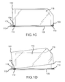
- FIG. 1C illustrates the mistake proof contour gauge including fixture 102 and lacing fixture 106 measuring a packed emergency evacuation device in contour, in accordance with various embodiments.
- Fixture 102 may be placed over packed emergency evacuation device 118 on lacing fixture 106.
- Fixture 102 may lie with the perimeter of opening 101 flat against lacing fixture 106.
- Packed emergency evacuation device 118 may be inside of fixture 102 for measurement.
- a pack within contour may be spaced from surfaces 103 or contacting surfaces 103 while fixture 102 lays substantially flat against lacing fixture 106 with fixture 102 placed over packed emergency evacuation device 118.
- Contacts 104 and contacts 110 may be electrically coupled to complete a circuit and activate indicator 114.
- output panel 112 may indicate that fixture 102 is flat against lacing fixture 106 with indicator 114. Visual inspection of packed emergency evacuation device 118 through surfaces 103 of fixture 102 may further indicate that packed emergency evacuation device 118 is packed within contour. In various embodiments without contacts 104 and contacts 110 or output panel 112, visual inspection while fixture 102 lay flat over lacing fixture 106 may be the only indication that packed emergency evacuation device 118 is packed within contour.
- FIG. 1D illustrates the mistake proof contour gauge including fixture 102 and lacing fixture 106 indicating that packed emergency evacuation device 118 not in contour, in accordance with various embodiments.
- Packed emergency evacuation device 118 may be placed on lacing fixture 106.
- Fixture 102 may be placed over packed emergency evacuation device 118 but may not sit flat on lacing fixture 106.
- One or more contacts 104 on fixture 102 may not contact the corresponding contact 110 on lacing fixture 106.
- Fixture 102 may be pressed against lacing fixture 106 with a weight to press down packed emergency evacuation device 118.
- Protruding portion 119 of packed emergency evacuation device 118 may press against fixture 102 to prevent fixture 102 from lying completely flat against lacing fixture 106.
- Output panel 112 may indicate that fixture 102 is not flat against lacing fixture 106.
- protruding portion 119 of packed emergency evacuation device 118 may be identified as a problem area on packed emergency evacuation device 118 and signal a need to repack packed emergency evacuation device 118.
- FIG. 2A illustrates a contour gauge with continuous surfaces and contacts to activate pressure sensitive switches, in accordance with various embodiments.
- Contour gauge 120 includes a fixture 122 for placement over a packed emergency evacuation device.
- Fixture 122 may comprise a polyhedron shape with opening 121 on one or more sides to enable placement of fixture 122 over a packed emergency evacuation device.
- the shape of fixture 122 may be specific to a certain type of aircraft so that an emergency evacuation device may be packed to the specific dimensions of various aircraft.
- Surfaces 123 of fixture 122 may be rigid to limit deformation when fixture 122 is placed over a packed emergency evacuation device.
- Surfaces 123 of fixture 122 may be at least one of translucent or transparent to allow visual inspection of a packed emergency evacuation device through surfaces 123.
- Fixture 122 may be made from thermoplastics (e.g., PMMA) or other materials that are at least one of translucent or transparent.
- fixture 122 may have contacts 124 around a substantially flat perimeter of opening 121. Each contact 124 may protrude from the perimeter of opening 121. Fixture 122 may be placed on a flat surface with opening 121 facing the flat surface so that contacts 124 are on the surface. Contacts 124 may comprise a pressure sensitive switch, for example, to indicate that contacts 124 are pressed against a flat surface. Contacts 124 may comprise stand offs, for example, to interface with an electronic switch responsive to pressure (e.g., a push button switch, tactile switch, pressure switch, or other switch suitable for activating when pressure is applied at an input surface) on a flat surface or interlock with a groove on an otherwise flat surface.
- pressure e.g., a push button switch, tactile switch, pressure switch, or other switch suitable for activating when pressure is applied at an input surface
- FIG. 2B illustrates a lacing fixture for use with a contour gauge having contacts to interact with contacts 130, in accordance with various embodiments.
- Lacing fixture 126 may serve as a surface to measure from using fixture 122 of FIG. 1A .
- Lacing fixture 126 may include a surface 128 to interface with fixture 122.
- Surface 128 of lacing fixture 126 may be a metallic material such as aluminum, titanium or other metals, or plastics such as PMMA.
- Lacing fixture 126 may have contacts 130 to interface with contacts 124 in FIG. 1A .
- contacts 130 may be pressure sensitive switches or grooves to interlock with contacts 124.
- Contacts 130 on lacing fixture 126 may correspond with locations of contacts 124 on fixture 122 so that contacts 130 and contacts 124 may interact with contacts 130.
- the contacts 124 may be stand offs to depress contacts 130, which may be pressure sensitive switches, and complete an electrical circuit when fixture 122 is placed over and contacting lacing fixture 126.
- lacing fixture 126 may include an output panel 132.
- Output panel 132 may include indicators 134 and 136 to indicate whether fixture 122 fits over a packed emergency evacuation device and is completely flat on lacing fixture 126.
- indicator 134 may be a light, LED, or other indicator that activates in response to all of contacts 124 being in contact with contacts 130.
- Indicator 136 may be a light, LED, or other indicator that turns on in response to one or more of contacts 124 not being in contact with contacts 130.
- pressure sensitive switches may depress and trigger a green light indicating that the pack is in contour or a red light may indicating that the pack is not within contour.
- references to "various embodiments”, “one embodiment”, “an embodiment”, “an example embodiment”, etc. indicate that the embodiment described may include a particular feature, structure, or characteristic, but every embodiment may not necessarily include the particular feature, structure, or characteristic. Moreover, such phrases are not necessarily referring to the same embodiment. Further, when a particular feature, structure, or characteristic is described in connection with an embodiment, it is submitted that it is within the knowledge of one skilled in the art to affect such feature, structure, or characteristic in connection with other embodiments whether or not explicitly described. After reading the description, it will be apparent to one skilled in the relevant art(s) how to implement the disclosure in alternative embodiments.
Landscapes
- Physics & Mathematics (AREA)
- General Physics & Mathematics (AREA)
- Professional, Industrial, Or Sporting Protective Garments (AREA)
- Switch Cases, Indication, And Locking (AREA)
Abstract
Description
- The present disclosure relates to emergency evacuation devices, and, more specifically, to a mistake proof contour gauge for measuring packed emergency evacuation devices.
- Door mounted evacuation systems may be mounted to aircraft doors and covered by a bustle or decorative cover. A gap or clearance between the packed evacuation system and the bustle or decorative cover tends to limit interference with growth of a packed emergency evacuation slide resulting from atmospheric pressure differentials. The gap may provide space for moving parts to work within the door and tends to ensure a smooth, predictable drop of the evacuation slide from the aircraft. The gap or clearance may be within a relatively small range (e.g., 0.5 in to 1 in or 1.3 cm to 2.5 cm) so that measurement of the pack should be accurate. The pack should be in contour at every surface when installed on the aircraft with no part of the pack being out of contour and encroaching on the gap or clearance.
- Grid patterned gauges may be used to measure pack sizes. However, grid shaped gauges may have gaps between points on the grid and may leave a substantial percentage of the pack unmeasured. Thus, parts of the pack directly under the grid may be measured while parts of the pack at the openings of the grid may extend out of contour beyond the grid. Furthermore, the gauges may be susceptible to human error when checking contact between a gauge and measuring surface that the gauge registers off. The human error may lead to ambiguity when interpreting contour reading results. In some instances, the gauge may be forced down with excessive force that may damage the packed evacuation slide.
- In various embodiments of the invention, a contour gauge may comprise a fixture including an opening and a first contact on a surface of the fixture. A lacing fixture may be configured to at least partially cover the opening. A second contact may be on the lacing fixture and may correspond to the first contact.
- Particular embodiments of the invention may include any of the following features, alone or in combination.
- The fixture may be made from a translucent or transparent material. The first contact may be an electrical contact. The second contact may be a pressure sensitive switch. An output panel with an indicator may be on the lacing fixture. The indicator may be a light, in particular at least one of a light bulb and an LED. The fixture may be made of polymethyl methacrylate. An output panel may be on the fixture. The fixture may be configured for measuring a packed emergency evacuation device. The fixture may comprise a surface configured to measure a contour of the packed emergency evacuation device. The contour gauge may further comprise an output panel configured to indicate that the contour is within specification. The fixture may comprise a contact on a perimeter of the opening. The fixture may comprise a pressure sensitive switch on a perimeter of the opening. The fixture may comprise a surface comprising a polyhedron shape.
- Exemplary embodiments of the invention further include a fixture for measuring a packed emergency evacuation device that may comprise a transparent or translucent surface configured to measure a contour of the packed emergency evacuation device. An opening may be opposite the transparent or translucent surface.
- Particular embodiments of the invention may include any of the following features, alone or in combination.
- A contact may be on a perimeter of the opening. A pressure sensitive switch may be on a perimeter of the opening. An output panel may be configured to indicate when the contour is within specification. The output panel may include a light, in particular at least one of a light bulb and an LED. The transparent or translucent surface may be made of polymethyl methacrylate. The transparent or translucent surface may be formed into a polyhedron shape.
- The foregoing features and elements may be combined in various combinations without exclusivity, unless expressly indicated otherwise. These features and elements as well as the operation thereof will become more apparent in light of the following description and the accompanying drawings. It should be understood, however, the following description and drawings are intended to be exemplary in nature and non-limiting.
- The subject matter of the present disclosure is particularly pointed out and distinctly claimed in the concluding portion of the specification. A more complete understanding of the present disclosure, however, may best be obtained by referring to the detailed description and claims when considered in connection with the figures, wherein like numerals denote like elements.
-
FIG. 1A illustrates a measuring fixture with continuous surfaces and electrical contacts, in accordance with various embodiments; -
FIG. 1B illustrates a lacing fixture for use with a measuring fixture having electrical contacts, in accordance with various embodiments; -
FIG. 1C illustrates a mistake proof contour gauge measuring a packed emergency evacuation device in contour, in accordance with various embodiments; -
FIG. 1D illustrates the mistake proof contour gauge measuring a packed emergency evacuation device not in contour, in accordance with various embodiments; -
FIG. 2A illustrates a measuring fixture with continuous surfaces and protruding contacts to interact with a switch, in accordance with various embodiments; and -
FIG. 2B illustrates a lacing fixture for use with a measuring fixture having protruding contacts, in accordance with various embodiments. - The detailed description of exemplary embodiments herein makes reference to the accompanying drawings, which show exemplary embodiments by way of illustration. While these exemplary embodiments are described in sufficient detail to enable those skilled in the art to practice the inventions, it should be understood that other embodiments may be realized and that logical changes and adaptations in design and construction may be made in accordance with this invention and the teachings herein. Thus, the detailed description herein is presented for purposes of illustration only and not of limitation. The scope of the invention is defined by the appended claims. For example, the steps recited in any of the method or process descriptions may be executed in any order and are not necessarily limited to the order presented.
- Furthermore, any reference to singular includes plural embodiments, and any reference to more than one component or step may include a singular embodiment or step. Also, any reference to attached, fixed, connected or the like may include permanent, removable, temporary, partial, full and/or any other possible attachment option. Additionally, any reference to without contact (or similar phrases) may also include reduced contact or minimal contact. Surface shading lines may be used throughout the figures to denote different parts but not necessarily to denote the same or different materials.
-
FIG. 1A illustrates a fixture of a contour gauge with continuous surfaces and electrical contacts, in accordance with various embodiments.Contour gauge 100 includes afixture 102 for placement over a packed emergency evacuation device.Fixture 102 may comprise a polyhedron shape with opening 101 on one or more sides to enable placement offixture 102 over a packed emergency evacuation device. The shape offixture 102 may be specific to a certain type of aircraft so that an emergency evacuation device may be packed to the specific dimensions of different aircraft.Surfaces 103 may be continuous without openings insurfaces 103 where a pack may be out of contour.Surfaces 103 offixture 102 may be rigid to limit deformation whenfixture 102 is placed over a packed emergency evacuation device.Surfaces 103 offixture 102 may be translucent or transparent to allow visual inspection of a packed emergency evacuation device throughsurfaces 103.Surfaces 103 may be at least one of transparent or translucent. In that regard, the phrase at least one of transparent or translucent may refer to, with respect tosurfaces 103, one or more materials that transmit at least 0.5% of visible light throughsurfaces 103. Thus, surfaces 103 may allow visual inspection of the pack for gaps between the pack andfixture 102, or to visually see where the pack is pressing againstsurfaces 103 and not packed tightly enough.Fixture 102 may be made from thermoplastics such as polymethyl methacrylate (PMMA) or other translucent or transparent materials. - In various embodiments,
fixture 102 may havecontacts 104 around a substantially flat perimeter ofopening 101. Eachcontact 104 may be substantially coplanar withother contacts 104 to contact a flat surface whenfixture 102 is placed on the flat surface with opening 101 facing the flat surface.Contacts 104 may be flush with the perimeter ofopening 101, orcontacts 104 may protrude from perimeter ofopening 101. -
FIG. 1B illustrates a lacing fixture of a contour gauge having electrical contacts, in accordance with various embodiments.Lacing fixture 106 may serve as a surface to mate withfixture 102 ofFIG. 1A for measuring a packed emergency evacuation device.Lacing fixture 106 may havesurface 108 to interface withfixture 102.Surface 108 may comprise a metallic material such as aluminum, titanium or other metals, or plastics such as PMMA.Lacing fixture 106 may havecontacts 110 to make an electrical connection withcontacts 104 inFIG. 1A .Contacts 110 on lacingfixture 106 may correspond with locations ofcontacts 104 onfixture 102 so thatcontacts 110 andcontacts 104 may complete an electrical circuit whenfixture 102 is placed over and contactinglacing fixture 106. - In various embodiments, lacing
fixture 106 may include anoutput panel 112 attached to lacingfixture 106.Output panel 112 may includeindicators fixture 102 is flat on lacingfixture 106. For example,indicator 114 may be a light, LED, or other indicator that turns on in response to allcontacts 104 being in contact withcontacts 110.Indicator 116 may be a light, LED, or other indicator that activates in response to one or more ofcontacts 104 not being in contact withcontacts 110. In the foregoing example, a green light may indicate that the pack is in contour, while a red light may indicate that the pack is not within contour.Output panel 112 may be attached tofixture 102.Fixture 102 or lacingfixture 106 may include anindividual output panel 112 for eachcontact 104 or contact 110. -
FIG. 1C illustrates the mistake proof contourgauge including fixture 102 and lacingfixture 106 measuring a packed emergency evacuation device in contour, in accordance with various embodiments.Fixture 102 may be placed over packedemergency evacuation device 118 on lacingfixture 106.Fixture 102 may lie with the perimeter of opening 101 flat against lacingfixture 106. Packedemergency evacuation device 118 may be inside offixture 102 for measurement. A pack within contour may be spaced fromsurfaces 103 or contactingsurfaces 103 whilefixture 102 lays substantially flat against lacingfixture 106 withfixture 102 placed over packedemergency evacuation device 118.Contacts 104 andcontacts 110 may be electrically coupled to complete a circuit and activateindicator 114. - In various embodiments,
output panel 112 may indicate thatfixture 102 is flat against lacingfixture 106 withindicator 114. Visual inspection of packedemergency evacuation device 118 throughsurfaces 103 offixture 102 may further indicate that packedemergency evacuation device 118 is packed within contour. In various embodiments withoutcontacts 104 andcontacts 110 oroutput panel 112, visual inspection whilefixture 102 lay flat over lacingfixture 106 may be the only indication that packedemergency evacuation device 118 is packed within contour. -
FIG. 1D illustrates the mistake proof contourgauge including fixture 102 and lacingfixture 106 indicating that packedemergency evacuation device 118 not in contour, in accordance with various embodiments. Packedemergency evacuation device 118 may be placed on lacingfixture 106.Fixture 102 may be placed over packedemergency evacuation device 118 but may not sit flat on lacingfixture 106. One ormore contacts 104 onfixture 102 may not contact thecorresponding contact 110 on lacingfixture 106.Fixture 102 may be pressed against lacingfixture 106 with a weight to press down packedemergency evacuation device 118. Protrudingportion 119 of packedemergency evacuation device 118 may press againstfixture 102 to preventfixture 102 from lying completely flat against lacingfixture 106.Output panel 112 may indicate thatfixture 102 is not flat against lacingfixture 106. Upon visual inspection, protrudingportion 119 of packedemergency evacuation device 118 may be identified as a problem area on packedemergency evacuation device 118 and signal a need to repack packedemergency evacuation device 118. -
FIG. 2A illustrates a contour gauge with continuous surfaces and contacts to activate pressure sensitive switches, in accordance with various embodiments.Contour gauge 120 includes afixture 122 for placement over a packed emergency evacuation device.Fixture 122 may comprise a polyhedron shape with opening 121 on one or more sides to enable placement offixture 122 over a packed emergency evacuation device. The shape offixture 122 may be specific to a certain type of aircraft so that an emergency evacuation device may be packed to the specific dimensions of various aircraft.Surfaces 123 offixture 122 may be rigid to limit deformation whenfixture 122 is placed over a packed emergency evacuation device.Surfaces 123 offixture 122 may be at least one of translucent or transparent to allow visual inspection of a packed emergency evacuation device throughsurfaces 123.Surfaces 123 may allow visual inspection of the pack for gaps between the pack andfixture 122, or to visually see where the pack is pressing againstsurfaces 123 and not packed to contour.Fixture 122 may be made from thermoplastics (e.g., PMMA) or other materials that are at least one of translucent or transparent. - In various embodiments,
fixture 122 may havecontacts 124 around a substantially flat perimeter ofopening 121. Eachcontact 124 may protrude from the perimeter ofopening 121.Fixture 122 may be placed on a flat surface with opening 121 facing the flat surface so thatcontacts 124 are on the surface.Contacts 124 may comprise a pressure sensitive switch, for example, to indicate thatcontacts 124 are pressed against a flat surface.Contacts 124 may comprise stand offs, for example, to interface with an electronic switch responsive to pressure (e.g., a push button switch, tactile switch, pressure switch, or other switch suitable for activating when pressure is applied at an input surface) on a flat surface or interlock with a groove on an otherwise flat surface. -
FIG. 2B illustrates a lacing fixture for use with a contour gauge having contacts to interact withcontacts 130, in accordance with various embodiments.Lacing fixture 126 may serve as a surface to measure from usingfixture 122 ofFIG. 1A .Lacing fixture 126 may include asurface 128 to interface withfixture 122.Surface 128 of lacingfixture 126 may be a metallic material such as aluminum, titanium or other metals, or plastics such as PMMA.Lacing fixture 126 may havecontacts 130 to interface withcontacts 124 inFIG. 1A . For example,contacts 130 may be pressure sensitive switches or grooves to interlock withcontacts 124.Contacts 130 on lacingfixture 126 may correspond with locations ofcontacts 124 onfixture 122 so thatcontacts 130 andcontacts 124 may interact withcontacts 130. For example, thecontacts 124 may be stand offs to depresscontacts 130, which may be pressure sensitive switches, and complete an electrical circuit whenfixture 122 is placed over and contactinglacing fixture 126. - In various embodiments, lacing
fixture 126 may include anoutput panel 132.Output panel 132 may includeindicators fixture 122 fits over a packed emergency evacuation device and is completely flat on lacingfixture 126. For example,indicator 134 may be a light, LED, or other indicator that activates in response to all ofcontacts 124 being in contact withcontacts 130.Indicator 136 may be a light, LED, or other indicator that turns on in response to one or more ofcontacts 124 not being in contact withcontacts 130. For example, pressure sensitive switches may depress and trigger a green light indicating that the pack is in contour or a red light may indicating that the pack is not within contour. - Benefits, other advantages, and solutions to problems have been described herein with regard to specific embodiments. Furthermore, the connecting lines shown in the various figures contained herein are intended to represent exemplary functional relationships and/or physical couplings between the various elements. It should be noted that many alternative or additional functional relationships or physical connections may be present in a practical system. However, the benefits, advantages, solutions to problems, and any elements that may cause any benefit, advantage, or solution to occur or become more pronounced are not to be construed as critical, required, or essential features or elements of the inventions. The scope of the inventions is accordingly to be limited by nothing other than the appended claims, in which reference to an element in the singular is not intended to mean "one and only one" unless explicitly so stated, but rather "one or more." Moreover, where a phrase similar to "at least one of A, B, or C" is used in the claims, it is intended that the phrase be interpreted to mean that A alone may be present in an embodiment, B alone may be present in an embodiment, C alone may be present in an embodiment, or that any combination of the elements A, B and C may be present in a single embodiment; for example, A and B, A and C, B and C, or A and B and C.
- Systems, methods and apparatus are provided herein. In the detailed description herein, references to "various embodiments", "one embodiment", "an embodiment", "an example embodiment", etc., indicate that the embodiment described may include a particular feature, structure, or characteristic, but every embodiment may not necessarily include the particular feature, structure, or characteristic. Moreover, such phrases are not necessarily referring to the same embodiment. Further, when a particular feature, structure, or characteristic is described in connection with an embodiment, it is submitted that it is within the knowledge of one skilled in the art to affect such feature, structure, or characteristic in connection with other embodiments whether or not explicitly described. After reading the description, it will be apparent to one skilled in the relevant art(s) how to implement the disclosure in alternative embodiments.
- Furthermore, no element, component, or method step in the present disclosure is intended to be dedicated to the public regardless of whether the element, component, or method step is explicitly recited in the claims. No claim element herein is to be construed under the provisions of 35 U.S.C. 112(f), unless the element is expressly recited using the phrase "means for." As used herein, the terms "comprises", "comprising", or any other variation thereof, are intended to cover a non-exclusive inclusion, such that a process, method, article, or apparatus that comprises a list of elements does not include only those elements but may include other elements not expressly listed or inherent to such process, method, article, or apparatus.
Claims (14)
- A contour gauge (100, 120), comprising:a measuring fixture (102, 122) including an opening (101, 121);a first contact (104, 124) on a surface of the measuring fixture;a lacing fixture (106, 126) configured to at least partially cover the opening; anda second contact (110, 130) on the lacing fixture corresponding to the first contact.
- The contour gauge (100, 120) of claim 1, wherein the measuring fixture comprises at least one of a translucent material or a transparent material.
- The contour gauge (100, 120) of claim 1 or 2, wherein the first contact comprises an electrical contact.
- The contour gauge (100, 120) of any of the preceding claims, wherein the second contact comprises a pressure sensitive switch.
- The contour gauge (100, 120) of any of the preceding claims, further comprising an output panel (112, 132) on the lacing fixture (106, 126) including an indicator (114, 116, 134, 136).
- The contour gauge (100, 120) of claim 5, wherein the indicator comprises at least one of a light bulb and an LED.
- The contour gauge (100, 120) of any of the preceding claims, wherein the measuring fixture (102, 122) comprises polymethyl methacrylate.
- The contour gauge (100, 120) of any of the preceding claims, further comprising an output panel on the measuring fixture.
- The contour gauge (100, 120) of any of the preceding claims, wherein the measuring fixture (102, 122) is configured for measuring a packed emergency evacuation device.
- The contour gauge (100, 120) of claim 9, wherein the measuring fixture (102, 122) comprises a surface configured to measure a contour of the packed emergency evacuation device.
- The contour gauge (100, 120) of claim 10, further comprising an output panel configured to indicate that the contour is within specification.
- The contour gauge (100, 120) of any of the preceding claims, wherein the measuring fixture (102, 122) comprises a contact on a perimeter of the opening.
- The contour gauge (100, 120) of any of the preceding claims, wherein the measuring fixture (102, 122) comprises a pressure sensitive switch on a perimeter of the opening.
- The contour gauge (100, 120) of any of the preceding claims, wherein the measuring fixture (102, 122) comprises a surface comprising a polyhedron shape.
Applications Claiming Priority (1)
| Application Number | Priority Date | Filing Date | Title |
|---|---|---|---|
| US14/492,486 US9933242B2 (en) | 2014-09-22 | 2014-09-22 | Mistake proof contour gauge |
Publications (1)
| Publication Number | Publication Date |
|---|---|
| EP2998690A1 true EP2998690A1 (en) | 2016-03-23 |
Family
ID=54185895
Family Applications (1)
| Application Number | Title | Priority Date | Filing Date |
|---|---|---|---|
| EP15186245.5A Withdrawn EP2998690A1 (en) | 2014-09-22 | 2015-09-22 | Mistake proof contour gauge |
Country Status (2)
| Country | Link |
|---|---|
| US (1) | US9933242B2 (en) |
| EP (1) | EP2998690A1 (en) |
Families Citing this family (4)
| Publication number | Priority date | Publication date | Assignee | Title |
|---|---|---|---|---|
| US9933242B2 (en) * | 2014-09-22 | 2018-04-03 | Goodrich Corporation | Mistake proof contour gauge |
| CN109000532B (en) * | 2018-08-17 | 2020-08-18 | 上海芃佳智能科技股份有限公司 | Multi-module quick detection tool |
| US10794782B2 (en) | 2018-10-01 | 2020-10-06 | Microsoft Technology Licensing, Llc | Systems and methods of measuring torsional resistance in a hinge |
| CN116295129B (en) * | 2023-01-04 | 2023-08-25 | 武汉成华汽车饰件有限公司 | Novel automobile decorative cover production process and surface detection system thereof |
Citations (2)
| Publication number | Priority date | Publication date | Assignee | Title |
|---|---|---|---|---|
| WO2011036506A1 (en) * | 2009-09-04 | 2011-03-31 | Gyoengyoesi Gabor | Device for making foot imprints and method for making a three-dimensional foot mould using the foot imprint, especially for manufacturing footwear to size |
| CN102679848A (en) * | 2012-05-11 | 2012-09-19 | 苏州金牛精密机械有限公司 | Detection device for relative depth of hole and O-shaped groove in sealing cover |
Family Cites Families (22)
| Publication number | Priority date | Publication date | Assignee | Title |
|---|---|---|---|---|
| US4103428A (en) * | 1977-11-01 | 1978-08-01 | Guzick Lawrence L | Pipe joint alignment measuring tool |
| US4268967A (en) * | 1979-09-14 | 1981-05-26 | Brana Lejo C | Package sizer |
| US4868992A (en) * | 1988-04-22 | 1989-09-26 | Intel Corporation | Anode cathode parallelism gap gauge |
| US5473940A (en) * | 1994-01-14 | 1995-12-12 | Hunter Engineering Company | Caliper for use with wheel balancers |
| US5680709A (en) * | 1995-03-06 | 1997-10-28 | Stone; John W. | Alignment device |
| SE506800C2 (en) * | 1995-04-28 | 1998-02-16 | Rolf Bjoerkdahl | Device for checking the diameter of the balls and any damage to their perimeter |
| US5774997A (en) * | 1997-01-02 | 1998-07-07 | Performance Dynamics Llc | Golf ball out-of-round indicator |
| US6209215B1 (en) * | 1997-08-21 | 2001-04-03 | Steven W. Helms | Saddle joint contour gauge apparatus and method |
| US6357282B1 (en) * | 2000-10-18 | 2002-03-19 | Robert E. Benjamin | Tennis ball tester |
| US6688015B2 (en) * | 2001-04-05 | 2004-02-10 | Delta Air Lines, Inc. | System and method for selection of wheel bearings |
| US7024787B2 (en) * | 2004-04-01 | 2006-04-11 | United Technologies Corporation | Template for evaluating parts and method of using same |
| US7578070B1 (en) * | 2006-07-31 | 2009-08-25 | Stacy Lynch | Digital ring sizing device and associated method |
| US7845077B1 (en) * | 2006-10-25 | 2010-12-07 | Alulis Eric B | Method of manufacturing a sizing ring |
| US20080271333A1 (en) * | 2007-05-01 | 2008-11-06 | Min-Hsien Sung | Ball liner for golf |
| US7568294B2 (en) * | 2007-05-01 | 2009-08-04 | Min Hsien Sung | Combination ball clip and ball liner and ball clip for use with a ball liner |
| US7797852B2 (en) * | 2008-12-09 | 2010-09-21 | David Davila | Support devices and kits for piston rings |
| US8627768B2 (en) * | 2010-02-19 | 2014-01-14 | Byron Smith | Ball marking device |
| FR2963965B1 (en) * | 2010-08-20 | 2013-02-15 | Vallourec Mannesmann Oil & Gas | METHOD AND DEVICE FOR CONTROLLING A TUBULAR JOINT THREAD USED IN THE PETROLEUM INDUSTRY |
| US8191276B1 (en) * | 2011-04-12 | 2012-06-05 | Jung Kyun Yi | Golf ball liner |
| CN102840844B (en) * | 2011-06-20 | 2015-06-10 | 纬创资通股份有限公司 | Detection jig and detection method using the detection jig |
| CN102847752A (en) * | 2011-06-30 | 2013-01-02 | 深圳富泰宏精密工业有限公司 | Press-fit device |
| US9933242B2 (en) * | 2014-09-22 | 2018-04-03 | Goodrich Corporation | Mistake proof contour gauge |
-
2014
- 2014-09-22 US US14/492,486 patent/US9933242B2/en active Active
-
2015
- 2015-09-22 EP EP15186245.5A patent/EP2998690A1/en not_active Withdrawn
Patent Citations (2)
| Publication number | Priority date | Publication date | Assignee | Title |
|---|---|---|---|---|
| WO2011036506A1 (en) * | 2009-09-04 | 2011-03-31 | Gyoengyoesi Gabor | Device for making foot imprints and method for making a three-dimensional foot mould using the foot imprint, especially for manufacturing footwear to size |
| CN102679848A (en) * | 2012-05-11 | 2012-09-19 | 苏州金牛精密机械有限公司 | Detection device for relative depth of hole and O-shaped groove in sealing cover |
Also Published As
| Publication number | Publication date |
|---|---|
| US20160084629A1 (en) | 2016-03-24 |
| US9933242B2 (en) | 2018-04-03 |
Similar Documents
| Publication | Publication Date | Title |
|---|---|---|
| US9933242B2 (en) | Mistake proof contour gauge | |
| WO2020251931A8 (en) | Gas sensor with separate contaminant detection element | |
| JP3189990U (en) | Fastener with fastening force measurement function | |
| EP2752299A3 (en) | Tape cassette and tape printer | |
| JP2016177941A5 (en) | ||
| US20190154517A1 (en) | Heat flux meter and abnormality diagnosis device | |
| EP2869439A3 (en) | Load cell on EMA housing with trim resistors | |
| WO2017097960A3 (en) | Method and device for sensing pressure applied to a screen with at least one sensor means | |
| EP2886904B1 (en) | Integral housing load cell system and apparatus | |
| EP3270133A1 (en) | Sealing system for electronic pressure sensor | |
| US9835650B2 (en) | Packaged device adapter with parameter indication | |
| CN204136868U (en) | Grip gear detection device | |
| CN107560765A (en) | A kind of robot skin sense of touch detecting system and method | |
| JP2014085346A5 (en) | ||
| JP2007518993A (en) | Sensor with modular connection | |
| JP6867828B2 (en) | Capacitance sensor inspection machine and inspection method | |
| CN208872800U (en) | voltage detection device | |
| US7752927B2 (en) | Cable-type load sensor | |
| JP2014085259A5 (en) | Strain measuring device and strain gauge transducer | |
| JP3184781U (en) | Surface temperature sensor | |
| US9678117B2 (en) | Integral safety display for a test switch | |
| CN205664958U (en) | Simple and easy type push -pull effort meter | |
| WO2015114557A3 (en) | Miniaturized device for pressure measurements over a very wide range | |
| CN215832990U (en) | Automobile function control system assembly testing device | |
| CN204263853U (en) | Tyre tread depth detecting device |
Legal Events
| Date | Code | Title | Description |
|---|---|---|---|
| PUAI | Public reference made under article 153(3) epc to a published international application that has entered the european phase |
Free format text: ORIGINAL CODE: 0009012 |
|
| AK | Designated contracting states |
Kind code of ref document: A1 Designated state(s): AL AT BE BG CH CY CZ DE DK EE ES FI FR GB GR HR HU IE IS IT LI LT LU LV MC MK MT NL NO PL PT RO RS SE SI SK SM TR |
|
| AX | Request for extension of the european patent |
Extension state: BA ME |
|
| RIN1 | Information on inventor provided before grant (corrected) |
Inventor name: RAUTENBACH, HELPERUS R. Inventor name: RUEGSEGGER, NICK |
|
| 17P | Request for examination filed |
Effective date: 20160923 |
|
| RBV | Designated contracting states (corrected) |
Designated state(s): AL AT BE BG CH CY CZ DE DK EE ES FI FR GB GR HR HU IE IS IT LI LT LU LV MC MK MT NL NO PL PT RO RS SE SI SK SM TR |
|
| STAA | Information on the status of an ep patent application or granted ep patent |
Free format text: STATUS: THE APPLICATION IS DEEMED TO BE WITHDRAWN |
|
| 18D | Application deemed to be withdrawn |
Effective date: 20180404 |