EP2998247B1 - Assembly and method for machining optical lenses - Google Patents
Assembly and method for machining optical lenses Download PDFInfo
- Publication number
- EP2998247B1 EP2998247B1 EP15020175.4A EP15020175A EP2998247B1 EP 2998247 B1 EP2998247 B1 EP 2998247B1 EP 15020175 A EP15020175 A EP 15020175A EP 2998247 B1 EP2998247 B1 EP 2998247B1
- Authority
- EP
- European Patent Office
- Prior art keywords
- processing
- lenses
- devices
- transport track
- conveying
- Prior art date
- Legal status (The legal status is an assumption and is not a legal conclusion. Google has not performed a legal analysis and makes no representation as to the accuracy of the status listed.)
- Active
Links
Images


Classifications
-
- B—PERFORMING OPERATIONS; TRANSPORTING
- B24—GRINDING; POLISHING
- B24B—MACHINES, DEVICES, OR PROCESSES FOR GRINDING OR POLISHING; DRESSING OR CONDITIONING OF ABRADING SURFACES; FEEDING OF GRINDING, POLISHING, OR LAPPING AGENTS
- B24B13/00—Machines or devices designed for grinding or polishing optical surfaces on lenses or surfaces of similar shape on other work; Accessories therefor
- B24B13/0031—Machines having several working posts; Feeding and manipulating devices
- B24B13/0037—Machines having several working posts; Feeding and manipulating devices the lenses being worked by different tools, e.g. for rough-grinding, fine-grinding, polishing
-
- B—PERFORMING OPERATIONS; TRANSPORTING
- B24—GRINDING; POLISHING
- B24B—MACHINES, DEVICES, OR PROCESSES FOR GRINDING OR POLISHING; DRESSING OR CONDITIONING OF ABRADING SURFACES; FEEDING OF GRINDING, POLISHING, OR LAPPING AGENTS
- B24B27/00—Other grinding machines or devices
- B24B27/0023—Other grinding machines or devices grinding machines with a plurality of working posts
-
- B—PERFORMING OPERATIONS; TRANSPORTING
- B24—GRINDING; POLISHING
- B24B—MACHINES, DEVICES, OR PROCESSES FOR GRINDING OR POLISHING; DRESSING OR CONDITIONING OF ABRADING SURFACES; FEEDING OF GRINDING, POLISHING, OR LAPPING AGENTS
- B24B27/00—Other grinding machines or devices
- B24B27/0069—Other grinding machines or devices with means for feeding the work-pieces to the grinding tool, e.g. turntables, transfer means
-
- B—PERFORMING OPERATIONS; TRANSPORTING
- B29—WORKING OF PLASTICS; WORKING OF SUBSTANCES IN A PLASTIC STATE IN GENERAL
- B29D—PRODUCING PARTICULAR ARTICLES FROM PLASTICS OR FROM SUBSTANCES IN A PLASTIC STATE
- B29D11/00—Producing optical elements, e.g. lenses or prisms
- B29D11/00009—Production of simple or compound lenses
- B29D11/00038—Production of contact lenses
- B29D11/00125—Auxiliary operations, e.g. removing oxygen from the mould, conveying moulds from a storage to the production line in an inert atmosphere
- B29D11/0023—Transferring contact lenses
-
- B—PERFORMING OPERATIONS; TRANSPORTING
- B29—WORKING OF PLASTICS; WORKING OF SUBSTANCES IN A PLASTIC STATE IN GENERAL
- B29D—PRODUCING PARTICULAR ARTICLES FROM PLASTICS OR FROM SUBSTANCES IN A PLASTIC STATE
- B29D11/00—Producing optical elements, e.g. lenses or prisms
- B29D11/00009—Production of simple or compound lenses
- B29D11/00423—Plants for the production of simple or compound lenses
-
- B—PERFORMING OPERATIONS; TRANSPORTING
- B29—WORKING OF PLASTICS; WORKING OF SUBSTANCES IN A PLASTIC STATE IN GENERAL
- B29D—PRODUCING PARTICULAR ARTICLES FROM PLASTICS OR FROM SUBSTANCES IN A PLASTIC STATE
- B29D11/00—Producing optical elements, e.g. lenses or prisms
- B29D11/00009—Production of simple or compound lenses
- B29D11/00432—Auxiliary operations, e.g. machines for filling the moulds
-
- B—PERFORMING OPERATIONS; TRANSPORTING
- B65—CONVEYING; PACKING; STORING; HANDLING THIN OR FILAMENTARY MATERIAL
- B65G—TRANSPORT OR STORAGE DEVICES, e.g. CONVEYORS FOR LOADING OR TIPPING, SHOP CONVEYOR SYSTEMS OR PNEUMATIC TUBE CONVEYORS
- B65G37/00—Combinations of mechanical conveyors of the same kind, or of different kinds, of interest apart from their application in particular machines or use in particular manufacturing processes
- B65G37/02—Flow-sheets for conveyor combinations in warehouses, magazines or workshops
-
- B—PERFORMING OPERATIONS; TRANSPORTING
- B65—CONVEYING; PACKING; STORING; HANDLING THIN OR FILAMENTARY MATERIAL
- B65G—TRANSPORT OR STORAGE DEVICES, e.g. CONVEYORS FOR LOADING OR TIPPING, SHOP CONVEYOR SYSTEMS OR PNEUMATIC TUBE CONVEYORS
- B65G43/00—Control devices, e.g. for safety, warning or fault-correcting
- B65G43/10—Sequence control of conveyors operating in combination
Definitions
- the present invention relates to a system for processing optical lenses and a method for processing optical lenses.
- the processing of optical lenses takes place in several steps or in several separate processing facilities.
- the machining may in particular comprise shaping or machining, polishing, coating, testing, marking, coating and / or cleaning.
- the WO 2008/042277 A1 discloses an apparatus for processing optical lenses, the apparatus comprising various processing means and a transfer system between the processing means. A processing line for serial processing is formed. The lenses are thus conveyed from one processing device to the next processing device until the lenses have passed through all the processing devices.
- the processing equipment and transfer system with conveyors are controlled by a central computer or controller.
- the DE 41 07 084 A1 discloses an automatic conveyor system for transporting objects between production areas, each consisting of one or more manufacturing stations of the same type and arranged at predetermined intervals in two parallel rows. Between two adjacent production areas a conveyor is arranged. Further, a further conveyor for transporting the objects between each other remote production areas is arranged between the two parallel rows. In addition, a further conveyor with a driverless Rangierwagen with an associated loading robot is provided between the individual production stations. The transfer system and conveyors are controlled by a central control computer.
- the GB 1 567 587 A discloses a work transfer system for selectively conveying two independently operating processing means by means of endless conveyors.
- the US 6,039,899 A and the US 6,071,440 A disclose a facility for casting and curing contact lenses. Pallets with front mold halves and pallets with back mold halves are fed by separate belt conveyors to a transfer device which alternately transfers the pallets in the desired order to another belt conveyor.
- the WO 2010/012364 A1 discloses a system for sorting goods to load the goods in an orderly order in a transport vehicle.
- the DE 10 2007 059 303 A1 discloses a system with a main conveyor belt having at least two tracks running in the same direction.
- An outer lane serves as a passing lane on which workpieces or workpiece carriers which are not to be fed for processing are transported further.
- a change from one transport lane to another transport lane is effected by slides and associated stamps.
- transverse conveyors with conveyor belts running in the opposite direction are assigned to each processing station, wherein workpieces or workpiece carriers to be processed are discharged via corresponding switches from the main conveyor belt to the transverse conveyors for processing in the respective processing station.
- the known system has a relatively large footprint and requires in addition to the main conveyor belt for each processing station two cross conveyor belts. This does not allow an optimal workflow.
- the DE 30 28 283 A1 discloses a similar manufacturing system.
- the US 4,727,684 A relates to a system for surface treatment, for example, for deburring, workpieces.
- the workpieces are placed together with abrasives in barrels, which are transported through the plant.
- a surface treatment of the workpieces is carried out by rotating the barrels so that the surface treatment of the workpieces by the abrasive material takes place in the barrels.
- the barrels can optionally be conveyed to one of several surface treatment devices and conveyed away again.
- the DE 10 2004 021 696 A1 relates to a device for processing optical lenses.
- a processing line formed of a blocking station, a processing station thereafter for machining the lenses, and a polishing station further thereafter for polishing the lenses.
- the three stations are each connected to each other via a conveyor belt, so that the transport of the lenses according to their processing only takes place from one station to the next and these are automatically transferred between the stations.
- the DE 198 15 728 A1 relates to a system for shaping the edges of spectacle lenses with a plurality of similar processing machines between a common conveyor belt for feeding and a common conveyor belt for conveying away spectacle lenses, so that the spectacle lenses are optionally only one of the processing machines zu commentbar.
- the present invention has for its object to provide a system for processing optical lenses and a method for processing optical lenses, wherein an optimized processing and handling with high flexibility and / or small footprint, especially taking into account different processing speeds or capacities of different processing facilities is possible or be, in particular wherein an extension of the system is very easy.
- a transfer system of the system preferably has a return connection for the return or circulation of lenses or lens carriers.
- the return conveyor connection in particular connects a first or second transport track, particularly preferably in the region of the beginning and end and / or to form a circuit or the possibility for circulation or circulation.
- each processing device is assigned its own conveying device. Between the various processing devices with the associated conveyors each transfer devices are arranged.
- the transfer devices and the conveying devices of the processing devices form a first, in particular at least substantially rectilinear, transport track.
- the transfer devices are designed for receiving and temporary buffering and for further conveying on demand of at least one lens or lens carrier optionally to a subsequent processing device or conveying device or to a second transport track. This enables a compact design and flexible processing.
- the conveying device assigned to a processing device is in the respective processing device integrated and / or attached to these (fixed).
- the respective conveyor ends at least substantially in the alignment or extension of one side of the processing device.
- the length of the conveyor preferably corresponds at least substantially to the width of the respective processing device. This is conducive to a compact design, in particular a system with multiple processing facilities.
- the transfer devices between the processing devices make it possible, once a lens or a pair of lenses has been processed, to move a processing device or the conveying device associated with the processing device freely again.
- a processed lens or a lens carrier with at least one processed lens can namely be further conveyed to the downstream transfer device. This takes up the processed lens or the lens carrier, so that now the processing device and its conveyor are free to receive the next lens or the next lens carrier of a transfer system, in particular a upstream transfer device.
- idle times can be minimized and thus optimized utilization or optimized throughput can be achieved.
- the transfer devices and the conveying devices of the processing devices for independently conveying the lenses or lens carriers are independently controllable or drivable.
- the conveyors can, for example, stop the respective lens or the respective lens carrier, move it forward or, if necessary, even move it backwards.
- a rectilinear and / or continuous (first) transport track for the lenses or lens carriers is formed from the conveyors of the processing devices and the transfer devices according to the present invention. This allows a compact construction.
- the transfer devices are preferably designed for selective further conveyance to a subsequent conveying device or processing device or to the second transport track, thus in each case preferably form a switch.
- the transfer devices thus preferably allow a change from the first transport track to the second transport track.
- the transfer devices also allow a reverse change from the second transport track to the first transport track. This allows a simple structure and a very flexible process, since lenses or lens wearer can switch between the transport tracks as needed.
- the second transport track can in particular be used as a bypass track to handle individual processing facilities.
- the second transport track preferably runs parallel to the first transport track and / or at least substantially rectilinearly.
- the second transport track is preferably controllable independently of the first transport track.
- the second transport track is preferably constructed of a plurality of conveyors which can be controlled or driven independently of one another and which form the second transport track one behind the other with transfer devices or changing devices arranged therebetween. This allows optimized delivery, wherein in particular lenses or lens carriers can be conveyed or transported on a conveying device of the second transport track independently of the conveyance of other lenses or lens carriers on another conveying device of the second transport track.
- the transfer devices each have a receiving area for the temporary buffering of at least one lens or at least one lens carrier.
- a recording and intermediate storage of a lens or a lens carrier after prior processing in a processing device can be forwarded or forwarded in due course to another processing device or to another transport track or conveying device of the transfer system.
- this recording or temporary storage can also serve to additionally receive a different lens or another lens carrier from the transfer device by appropriate transverse conveyance and forward it (first) to a downstream processing device or its delivery device. Subsequently, the lens or the lens carrier from the receiving area can then either be forwarded to the downstream processing device or to another conveyor or transport track or further promoted. Accordingly, a very flexible and needs-based processing is possible.
- the transfer devices or their receiving area particularly preferably form corresponding receiving buffers for lenses or lens carriers. This makes it possible, for example, that other conveying devices or a second transport track or further transport tracks of the transfer system, at least substantially can continuously promote. This allows a substantial simplification of the control.
- the second transport track and corresponding connections or cross-conveyor devices between the first and second transport track, particularly preferably between each processing device, allow overtaking of lenses or lens carriers, for example, for processing lenses with special priority, and / or bypassing or selecting particular Machining or processing facilities.
- a lens made of polycarbonate can be conveyed to a processing device which is particularly suitable or set up for this purpose, while a lens made of another material, for example CR 39, can be conveyed to another processing device which is suitable or equipped for this purpose.
- the conveying direction of the second transport track and / or the transfer devices and / or the conveying devices of the processing devices is reversible. This allows a compact design and high flexibility in the processing.
- the transfer system preferably additionally has a third transport track for the parallel conveyance, in particular return conveyance, of lenses or lens carriers.
- the second and third transport tracks have opposite conveying directions to one another.
- the third transport track also preferably runs at least substantially rectilinearly and / or parallel to the other transport tracks. This allows a compact design and optimized delivery and thus optimized processing and utilization of processing machines.
- the third transport track is preferably similar or constructed as the second transport track.
- the third transport track of a plurality of successively arranged or in series conveyors is constructed with, if necessary, arranged therebetween transfer or change devices.
- the conveyors are preferably again independently for the independent promotion of lenses or lens carriers controllable.
- changing devices are provided for changing between the second and third transport track or the transport tracks.
- the changing devices may be formed by, or separate from, the transfer devices.
- the changing devices preferably have conveying devices for transversely conveying at least one lens or lens carrier for changing between the second and the third transport track or the transport tracks.
- the lenses or lens carriers are circulated or conveyed in a cycle, in particular in order to temporarily store them and / or to avoid stagnation in front of processing devices.
- This is preferably done in the second transport track in one direction and in the third transport track in the opposite direction, with corresponding cross conveyors or cross connections between these two transport tracks are used to allow the desired circulation or circulation promotion. So these transport tracks for storage or Caching the lenses or lens wearer can be used. Alternatively or additionally, unwanted congestion can thereby be avoided.
- lenses or lens carriers are removed from the circulation or from the circulation if a desired processing device is available. The discharging takes place, in particular, via a corresponding transverse conveying and / or by a change in the first transport track or by a change to a transfer device assigned or arranged upstream of the desired processing device.
- the transfer devices preferably each have a conveying device for the longitudinal conveying of at least one lens or lens carrier parallel to one of the transport tracks and additionally a conveying device for the transverse conveying of at least one lens or a lens carrier for changing the transport track.
- These conveyors are preferably independently controllable. This allows optimal promotion, wherein in particular the preferred temporary recording or intermediate storage of at least one lens or lens carrier, in particular on the conveyor for longitudinal conveying - particularly preferably in a receiving area before or upstream of the associated conveyor for transverse conveying - takes place, wherein the conveyor for longitudinal promotion then is formed sufficiently long.
- the conveying devices for the transverse conveying of the transfer devices or exchangeable devices or parts or sections thereof are preferably selectively raised and lowered by means of associated lifting devices.
- the cross-promotion can be used as needed, if this is actually needed. This is especially true if the conveyors are designed as belt or belt conveyor.
- individual or all conveyors are designed as belt or belt conveyor. This allows a simple and inexpensive construction and secure delivery of the lenses or lens carriers.
- the lenses are transported between the processing devices or from the transfer systems only by means of lens carriers or in lens carriers.
- lens carrier transport crates are particularly preferably used.
- the lens carriers preferably each receive at least one lens, in particular two lenses or a pair of lenses, in particular two associated spectacle lenses for spectacles.
- the plant or the transfer system preferably has a preferably common or central control device for controlling the transfer devices, wherein the conveyors of the processing devices of the respective processing device or their machine control and in particular independently and / or independently of the transfer system or the transfer devices are controllable or can be driven.
- This allows an optimized, in particular partially decentralized control. In this way it can be achieved, in particular, that the individual processing operations in the individual processing devices have priority and the transfer devices and further conveying devices of the transfer system convey the lenses or lens carriers only to the processing devices and away from them as required.
- one or more processing devices can automatically request or select lenses or lens carriers for processing or can be conveyed, more preferably independent of other processing facilities and / or a central system control and / or control device, where required for the processing production or processing data, in particular Processing plans andreachessstati, lens data o.
- the like As needed, from a particular central server, database system o. The like. Can be accessed or taken into account when needed. This allows an optimization of the machining process and is the flexible processing beneficial. Furthermore, this facilitates a simple and modular structure and an extension of the system.
- the transfer system or its components such as the transfer devices, the optional change devices and / or the other conveyors (not the conveyors of the processing facilities) are preferably connected via a Bussytem to a control device of the transfer system, such as a programmable logic controller, connected and controllable ,
- a control device of the transfer system such as a programmable logic controller, connected and controllable
- a cable with supply lines and control lines is used, to which the conveyors or other components of the Transfer system or the transfer devices and / or the processing facilities are connected. This facilitates a simple and modular construction or a simple connection and / or an extension of the system.
- a proposed method of processing is characterized in particular by the fact that the lenses or lens carriers with the lenses are optionally conveyed to different processing devices for independent processing of the lenses, the lenses or lens carriers being conveyed independently by conveyors in the processing devices, the lenses or lens carriers of Transfer devices between the processing facilities temporarily added and optionally further promoted to the next processing facility or a parallel transport track.
- the transfer devices are controlled by a preferably central or common control device, wherein the conveyors of the processing devices, however, are preferably controlled by the respective processing device or its machine control. This simplifies the control and in particular allows optimized processing in the individual processing devices. Further, an extension of the system and a connection of other processing facilities are thereby substantially facilitated.
- the required processing steps and their sequence for producing a finished lens from a lens or lens blank are defined in a so-called processing plan, but that in the case of several processing devices for the same processing, for example for polishing , the respective device and thus the concrete facilities to be used can be selected.
- the independent processing by the processing means is preferably to be understood that the processing in the respective device is independent of other processing and independent of the transfer system, but the order of the processing steps is given or maintained.
- the actual processing state is reflected in the processing status, which indicates in particular which processing has already taken place or is to take place next, with particular preference taking place with reference to the corresponding processing plan for the respective lens.
- the independent processing by the processing device is preferably to be understood that the processing means automatically or independently of a central control to be processed lenses or lens carrier with lenses to be processed - particularly preferably in consideration the required processing - to select or request and / or to be assisted.
- This selection can be done either at a logical level or at the physical level.
- the respective processing device for example, a job or a record with information about a lens to be processed from a data store, database server, a system control or the like. Select and then promote this lens or the corresponding lens carrier with this lens (leave).
- a processing device When selected in the physical plane, a processing device can, for example, detect or identify lenses or lens carriers to be processed with lenses-in particular by means of a sensor or the like-and, taking into account the respective job or data record with information about the required processing, a suitable lens or select an appropriate lens wearer and get promoted for editing.
- a processing device can, for example, detect or identify lenses or lens carriers to be processed with lenses-in particular by means of a sensor or the like-and, taking into account the respective job or data record with information about the required processing, a suitable lens or select an appropriate lens wearer and get promoted for editing.
- One aspect of the present invention therefore lies in particular in that the processing devices work at least as far as possible automatically or independently, so that particularly preferably the processing devices individually retrieve or request lenses or lens carriers from the transfer system to perform a required processing, and then the processed (n) return the lens (s) back to the transfer system, ie return it to the delivery or the delivery cycle.
- This independence or independence of the processing facilities simplifies the integration of additional or new processing facilities in the system essential.
- the transfer system preferably has at least one sensor, for example a barcode reading station or the like, for lenses or lens carriers and notifies an assigned processing device after appropriate detection and possibly evaluation of an identification or directly the processing status of a detected lens or a detected lens wearer with.
- the processing status can optionally be set by means of a central data memory, a central database, a central system control or the like queried or adjusted or found.
- the processing device can then autonomously request the detected lens or the detected lens carrier, if the processing device can perform the (next) required processing. In this type of request for lenses to be processed already existing processing facilities must not be updated or receive any special notice when new or additional processing facilities involved in the system and / or additional processing operations are scheduled.
- the transfer system - ie the belt or conveyor system - and / or controlled by a system control of the system, in particular because thereby the Promotion of the lenses or lens carrier along the processing facilities is controlled or influenced.
- the processing device may have its own sensor, in particular a barcode reading station or the like, for detecting and optionally identifying lenses or lens carriers.
- the processing device can pick up or request a detected lens or a detected lens carrier, in particular by direct control of a corresponding conveying device, transfer device, changing device or the like, if the respective processing device can perform the required processing.
- the processing device changes the processing status of the lens or the lens wearer - especially in a central database, system control or the like - and returns the processed lens or the lens wearer to the transfer system.
- the processing devices can be so independent and self-sufficient that they control the production flow or the delivery of the lenses or lens carriers.
- the respective conveyor must know the other conveyors on the transfer system or the system and her also the machining plan - ie the machining sequence - be known. If new processing facilities are added and / or if the processing plan changes, this must be communicated to each processing facility or filed or made accessible in a corresponding central database, system control or the like.
- Fig. 1 shows a schematic representation of a proposed device or system 1 for processing of optical lenses 2, so a lens processing system.
- the processing of lenses for spectacles or spectacle lenses will be discussed in more detail.
- these embodiments also apply correspondingly to the processing of other lenses 2 or generally optical workpieces.
- the system 1 has a plurality of separate processing devices 3 for the independent processing of the lenses 2.
- the installation 1 may in particular comprise at least one processing device 3A for blocking (temporarily connecting to a holder) lenses 2, a processing device 3B for temporarily storing lenses 2 (preferably for cooling after blocking), a processing device 3C for shaping, in particular cutting or milling Processing of lenses 2, a processing device 3D for polishing lenses 2, a processing device 3E for testing or measuring lenses 2, a processing device 3F for marking lenses 2 and / or a processing device 3G for coating lenses 2 (in FIG Fig. 5 indicated).
- a plurality of similar processing devices 3, for example two or more processing devices 3 for the same processing may be present or integrated into the plant 1.
- a plurality of processing devices 3C for shaping processing, a plurality of processing devices 3D for polishing, etc. may be provided. This depends in particular on the throughput of the various processing devices 3 and / or the desired processing. Namely, a particular advantage of the proposed plant 1 is that additional processing devices 3 can also be integrated or integrated into the plant 1 very easily later as required, ie extensions can be made very simply.
- the system 1 has a transfer system 4 for transporting the lenses 2 or lens carriers 5 with the lenses 2 to and from the processing devices 3.
- the transfer system 4 feeds the lenses 2 or lens carriers 5 in particular to the processing devices 3 and / or transports or conveys the lenses 2 or lens carriers 5 after processing has been carried out in a processing device 3 to another processing device 3 or to a dispensing station 6.
- the dispensing station 6 may be formed, for example, as a transfer device, rolling table or other storage device.
- the system 1 preferably also has a receiving station 7, which serves for receiving lenses 2 to be processed or lens carriers 5 carrying the lenses 2 to be processed.
- the dispensing station 6 is preferably arranged separately from the receiving station 7, for example on an opposite side in the illustrated example.
- the receiving station 7 and the dispensing station 6 may, if necessary, also be arranged side by side or adjacent, as in FIG Fig. 1 indicated by the additionally shown as an alternative next to the receiving station 7 dispensing station 6 ', and / or be formed by a common device or the like. And / or be arranged at any point of the transfer system 4.
- Each processing device 3 is assigned its own conveying device 8 for, in particular, linear conveying of at least one lens 2 or a lens carrier 5.
- the associated conveyor 8 is integrated in the respective processing device 3 or installed or attached to this.
- the conveyor 8 is preferably designed as a conveyor belt.
- the conveying devices 8 of the processing devices 3 are preferably each of the respective processing device 3 and the machine control (in Fig. 1 not shown) controlled.
- the processing means 3 are as compact as possible or at least substantially formed like a quarry or with a rectangular base, the conveyor means 8 each preferably behind, so on a control or operating panel 17 of the processing device 3 opposite side, or on a narrow side of the respective processing device 3 are arranged. In principle, however, a different arrangement, in particular on a longitudinal side of the respective processing device 3 is possible.
- the conveying devices 8 do not protrude laterally beyond the respective processing device 3, or only slightly and / or by a uniform amount.
- the length of the conveyor 8 corresponds at least substantially to the width of the respective processing device 3.
- the passage width between adjacent processing devices 3 is preferably determined by a transfer device 9 arranged therebetween, which will be discussed later.
- the aisle width is for example about 60 cm.
- a passage between adjacent processing devices 3 is required or desirable in particular for maintenance or repair purposes and / or also for refilling resources or the like.
- the processing devices 3 are preferably arranged or placed next to each other so that the conveyors 8 extend at least substantially in a line or lie one behind the other and / or a preferably at least substantially rectilinear first transport track T1 (dash-dotted lines in FIG Fig. 1 indicated).
- first transport track T1 and / or a second transport track T2 also correspond to a polygonal course, that is to say that they can be constructed from different rectilinear sections or sections and run, for example, over a corner or in a U-shape.
- a plurality of processing devices 3 are preferably arranged in a row such that these processing devices 3 are arranged with their conveying devices 8 along this path or section.
- the transfer system 4 preferably has transfer devices 9, which are each arranged between two adjacent processing devices 3 (one row). Preferably, transfer devices 9 are arranged between some or all (immediately) adjacent processing devices 3.
- the transfer devices 9 are preferably each for receiving and temporarily temporarily storing at least one lens 2 or a lens carrier 5 and also for further conveying this lens 2 or this lens carrier 5 optionally to the conveyor 8 of a subsequent processing device 3 or to a second transport track T2 of the system or the transfer system 4 is formed.
- the second transport track T2 preferably likewise runs like the first transport track T1 at least substantially rectilinearly or polygon-like and / or parallel to the first transport track T1.
- the receiving station 7 is preferably designed to receive lenses 2 to be processed or lens carriers 5 with the lenses 2 to be processed.
- the receiving station 7 may in particular be designed in such a way that it outputs the lenses 2 to be processed or the lens carriers 5 optionally to the transport track T1 or T2.
- the transfer system 4 preferably has a plurality of conveyors 10, which are arranged in particular in series or behind one another, to form the second transport track T2.
- the lenses 2 or lens carriers 5 can therefore be transported or conveyed along this second transport track T2 by means of one or more conveyors 10.
- the conveying devices 10 of the second transport track T2 are preferably controllable independently of one another in order to be able to convey lenses 2 or lens carriers 5 independently of one another or in sections along the second transport track T2.
- a lens 2 or a lens carrier 5 can be stopped on a conveyor 10, while another lens 2 or another lens carrier 5 is further conveyed on another conveyor 10 of the second transport track T2.
- stopping of individual lenses 2 or lens carriers 5 can also be achieved by means of corresponding stop devices or the like (see, for example, stop devices 18 in the transport track T2 in FIG Fig. 3 ) can be realized, so that in this case, the conveyor (s) 10 can be operated on or continuously. This is preferably true for some or all, transport tracks or conveyors.
- the transfer devices 9 can be arranged between the conveyors 10 of the second transport track T2. Alternatively, however, the transfer devices 9 may alternatively convey directly to an associated conveyor 10 of the second transport track T2. In this case, the conveyors 10 can be arranged one behind the other without the interposition of transfer means 9, as in FIG Fig. 1 and 3 indicated.
- the conveying direction of the first transport track T1 is in Fig. 1 indicated by an arrow F1.
- the second transport track T2 preferably conveys in the same direction, as indicated by arrow F2.
- the second transport track T2 serves in particular to allow lenses 2 or lens carriers 5 to be conveyed past individual processing devices 3.
- a forwarding for better utilization of processing equipment 3, for promotion to a specific processing device 3 for a special processing, due to a failure or utilization of a processing device 3 or due to unnecessary processing by a processing device 3, may be desired or required.
- the forwarding can also serve to overtake other lenses 2 or lens carriers 5, for example, if priority processing of a specific lens 2 or several specific lenses 2 is to take place.
- the lenses 2 or lens carriers 5 can change between the first and second transport tracks T1, T2 by means of the transfer devices 9.
- such a change is possible between each of the processing devices 3 and / or by means of each transfer device 9 and / or in each direction, ie from the first to the second transport track T1, T2 and vice versa.
- the system 1 or the transfer system 4 preferably has a third transport track T3, which preferably runs at least substantially rectilinearly and / or parallel to the other transport tracks T1 and T2.
- the conveying direction F3 of the third transport track T3 is preferably directed counter to the conveying directions F1 and F2 of the other transport tracks T1 and T2, or preferably runs backwards.
- the transport track T3 thus serves in particular for a return conveyance or opposite conveyance of lenses 2 or lens carriers 5, for example for reinsertion (via corresponding change possibilities) into the first or second transport track T1, T2 for further processing or for return conveyance, for example to the dispensing station 6 '.
- the third transport track T3 is preferably constructed in accordance with or similar to the second transport track T2, particularly preferably from a plurality of conveyors 10 arranged in a line or one behind the other, as in FIG Fig. 1 indicated.
- the conveying devices 10 of the third transport track T3 are preferably independently controllable or drivable again, so that an independent conveying of lenses 2 or lens carriers 5 along the third transport track T3 is possible, as has already been described in principle for the second transport track T2 above , so that the relevant statements apply in particular corresponding or supplementary.
- stopping individual lenses 2 or lens carriers 5 can also be realized by corresponding stop devices or the like (not shown), so that in this case the conveyor (s) 10 can be operated further or continuously.
- the system 1 or the transfer system 4 preferably has changing devices 11 for changing between transport tracks T, in particular between the second transport track T2 and third transport track T3, ie optionally from the second transport track T2 to the third transport track T3 and vice versa.
- the changing devices 11 can be arranged in each case between the conveying devices 10 in the two transport tracks T2 and T3. In this case, the changing devices 11 also serve a certain further promotion in the direction of the respective conveying direction F2 or F3, ie the longitudinal conveying. Alternatively, however, the changing devices 11 can also be integrated in associated conveying devices 10 or interact with them in such a way that the alternating directions 11 only serve for transverse conveying, that is to say merely for conveying between the respective transport tracks T2 and T3. This type of integration is preferred and shown in the illustrated example.
- the transfer devices 9 are preferably correspondingly integrated in the second transport track T2 or in the associated transport device 10 of the second transport track T2.
- the transfer means 9 in the illustrated embodiment preferably do not effect longitudinal conveyance or further conveyance in the second transport track T2 in the conveying direction F2.
- the changing devices 11 and the transfer devices 9 can also be combined or arranged in extension or form a structural unit, as in FIG Fig. 1 indicated in the area of the dispensing station 6 by way of example.
- all or individual transfer devices 9 or exchangeable devices 11 can also be designed such that they additionally allow an optional transverse conveyance up to the optional transport track T3 and / or a change of demand between all transport tracks T1 to T3 or between the transport tracks T1 and T3.
- the system 1 in the region of an end or the dispensing station 6, in particular if it is spatially separated from the feeding station 7, an associated transfer device 9 and / or changing device 11, as in Fig. 1 indicated.
- changing means 11 are arranged in the region of the beginning and the end of the third transport track T3 and / or between one or more, in particular to allow a circulation or circulation or circulation K of lenses 2 or lens carriers 5, as in Fig. 5 . 6 and 7 indicated.
- the system 1 or the transfer system 4 preferably has a transfer control or control device 12 - in particular a programmable logic controller - for controlling the transfer devices 9 and / or conveyors 10 and, if present, the changing devices 11 and optionally the receiving station 7 and / or dispensing station 6 on, like in Fig. 1 indicated.
- the connection is particularly preferably via a bus system 13, which in Fig. 1 indicated by dashed lines.
- the bus system 13 has a bus cable containing all supply lines and / or control lines.
- 8 preferably form no part of the transfer system 4 or the transfer control.
- the conveying devices 8 of the processing devices 3 are preferably conveyed by the processing devices 3 themselves or directly or by their machine controls (see machine controls 20 in FIG Fig. 6 and 7 ) controlled.
- the conveyors 8 are accordingly preferably respectively connected to the associated processing device 3 and the machine controller 20 for controlling the respective conveyor 8.
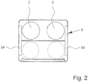
- Fig. 2 shows a schematic plan view of a preferred embodiment of a lens carrier 5 for receiving at least one, in the illustrated example, in particular two or more to be processed lenses 2.
- a lens carrier 5 for receiving at least one, in the illustrated example, in particular two or more to be processed lenses 2.
- lens processing or spectacle lens processing usually two lenses to be processed 2 and a pair of lenses are received by a lens carrier 5 , This is also preferred here.
- the lens carrier 5 preferably has a coding 5A, for example a barcode or the like, with important processing data, data for identification and / or other information for both lenses 2 or for each lens 2 a separate coding 5A, as in FIG Fig. 2 hinted at.
- the coding 5A particularly preferably contains an identification or order number or the like for the respective lens (s) 2, so that by means of the identification or order number a processing plan and / or processing status or required processing steps, processing sequences, processing data and / or other information, for example via a corresponding server system, database system or the like, in particular a system controller 21, as in Fig. 6 indicated, determinable or retrievable.
- the distance between the lenses 2 in a lens carrier 5 is the same as the distance between a lens 2 in a lens carrier 5 to the adjacent lens 2 in an immediately adjacent lens carrier 5. This simplifies the handling or positioning, especially in the processing facilities 3.
- This Distance is preferably 130 mm in the illustrated embodiment.
- the length of the lens carrier 5 is preferably twice, so here 260 mm.
- the lens carrier 5 is preferably box-like in the illustrated embodiment and / or at least substantially square in plan view.
- the lens carrier 5 has in the illustrated embodiment preferably additional storage or recording places, for example, for tools, in particular polishing tools on, as in Fig. 2 indicated by dashed lines.
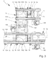
- Fig. 3 shows in a schematic representation or enlargement of Fig.1 a preferred construction of a proposed transfer device 9.
- the transfer device 9 preferably has a (first) conveyor 14 for longitudinal conveying (conveying in the direction F one of the transport tracks T, in particular the first transport track T1) and a (second) conveyor 15 for transverse conveying (conveying transversely or perpendicular to the conveying directions F or transport tracks T or to the transport track change).
- the conveyors 14 and 15 are preferably as well as the conveyors 8 and / or 10 designed as a belt or belt conveyor.
- the conveyors 10 preferably include belts or straps 10A and associated actuators 10B.
- the conveyors 14 preferably each have bands or straps 14A and associated drives 14B.
- the conveyors 15 preferably comprise belts or belts 15A and associated drives 15B.
- the transfer device 9 is preferably designed for receiving and temporarily storing or storing at least one lens 2 or a lens carrier 5 and, for this purpose, has in particular a bearing or receiving region 19, as in FIG Fig. 3 indicated by dashed lines.
- This or this is preferably formed in the illustrated embodiment by the conveyor 14, which has a sufficient length for this purpose.
- the length of the conveyor 14 is at least the simple length of a lens carrier 5, in the illustrated embodiment even at least twice the length of the lens carrier 5 to this preferably next to or in the conveying direction F1 before or upstream of the conveyor 15 for cross-promotion or record their lift table 15C or to be able to temporarily store.
- the receiving area 19 is preferably assigned a suitable stop device 18 (for example with a stop that can be moved or folded into the movement path or a singler) for stopping the or a lens carrier 5 in the receiving area 19 as required.
- the stop device 18 may stop or stop a lens carrier 5 - here in the receiving area 19 - in particular also when the conveyor 14 continues to run.
- suitable sensors 16 such as photoelectric sensors , Barcode reader or the like
- the length of the conveyor 14 or the transfer device 9 in the conveying direction F1 at least substantially equal to the distance between adjacent processing devices 3 and adjacent conveyors 8 and the aisle width between adjacent processing devices 3, as already mentioned, or at least the length of two lens carriers 5th
- processing devices 3 are preferably set up generally at least at substantially the same intermediate distance. Accordingly, preferably identical transfer devices 9 can be inserted or arranged therebetween.
- the conveying device 15 for transverse conveying has, as in Fig. 3 indicated in the transfer device 9 according to the illustrated embodiment, preferably an intermediate conveyor with belts or straps 15D between the two transport tracks T1 and T2 and between the conveyor 14 and the adjacent conveyor 10 on.
- the conveyor 15 preferably has a common drive 15B for driving the belts 15A and, if present, 15D.
- the bands or straps 15A are preferably arranged in pairs between the straps 14A of the conveyor 14 and the straps 10A of the conveyor 10 and are each preferably supported by a lifting element, in particular a lifting table 15C.
- the lifting element or the lifting table 15C or the lifting elements / lifting tables 15C and thus the associated bands or straps 15A are preferably (not shown) by means of an associated lifting device can be raised and lowered as needed.
- the conveyor 14 can receive and temporarily store or store a lens carrier 5 from an upstream processing device 3, in particular in the receiving region 19 and / or above the lifting table 15C or over the belts or straps 15A. If necessary, the transfer device 9 or its conveying device 14 can further convey the lens carrier 5 to the downstream processing device 3 or release it again. Alternatively, the transfer device 9 or its conveying device 15 can change the lens carrier 5 to the transport track T2, ie convey it crosswise. In this case, the lift table 15C is raised until the lens carrier 5 (in FIG Fig. 3 not shown) lifted and lifted off the belts or straps 14 A of the conveyor 14.
- the lens carrier 5 is conveyed by means of the bands or straps 15A - in the illustrated example via the optional intermediate conveyor or the straps or belts 15D - to the second transport track T2 or to the belts or straps 15A there.
- the transverse conveying and the lifting table 15C in the transport track T2 and in the conveyor 10 with or similar raised.
- a preferred lateral stop 15E which protrudes laterally upwards beyond the conveyor 10 or its bands or belts 10A, prevents the lens carrier 5 from being conveyed too far in the transverse direction or from the lens carrier 5 being conveyed laterally beyond the conveyor 10 ,
- the conveyor 15 or its lifting tables 15C are lowered again and thus the lens carrier 5 is transferred to the conveyor 10 or placed on the belts or straps 10A, so that now a promotion along the second transport track T2 by means of the conveyor 10 can take place ,
- the conveyor 15 is integrated for transverse conveying in the conveyor 10 for longitudinal conveying, since no separate conveyor for longitudinal conveying the transfer device 9 is provided in the second transport track 10, in contrast to the conveyor 14 for longitudinal conveying the transfer device 9 in the first transport track T1 , However, basically Such an additional conveyor 14 of the transfer device 9 may be provided in the second transport track T2.
- the transfer device 9 can not only for a change of the lens carrier 5 from the first transport track T1 to the second transport track T2, but of course for the reverse change, in particular for introducing a lens 2 or a lens carrier 5 in the transport track T1 for processing in one subsequent processing device 3, are used.
- the lens carrier 5 is positioned by the second transport track T2 or the associated conveyor 10 above the conveying device 15 for transverse conveying or its lifting table 15C in the second transport track T2.
- the positioning is preferably carried out by means of a stop device 18, for example by means of the stopping device 18 shown in dashed lines, which is arranged in particular in the second transport track T2 or after the lifting table 15C.
- the positioning of the transversely conveyed lens carrier 5 in the transport track T1 can in turn be facilitated or fixed by an optional lateral stop 15E.
- the transfer device 9 preferably serves both to introduce lenses 2 or lens carriers 5 into the first transport track T1 and to remove lenses 2 or lens carriers 5 from the transport track T2 to another transport track, here the second transport track T2.
- the transfer device 9 is in particular designed such that a lens 2 or a lens carrier 5 can be transversely conveyed or introduced into the first transport track T1, while another lens 2 or another lens carrier 5 is located in the receiving region 19 or temporarily stored there is cached.
- lenses 2 or lens carriers 5 can also be introduced between other lenses 2 or lens carriers 5 in the first transport track T1.
- the transfer device 9 allows a selective advancement of a lens 2 or a lens carrier 5 from the previous processing device 3 (in the first transport track T1) or from the receiving area 19 to the next processing device 3 as well as a discharging or Quer dealtn from the first transport track T1 to another transport track T, here the second transport track T2.
- the transfer device 9 thus forms a switch, with in particular upstream receiving area 19 for temporary storage.
- the transfer device 9 Since the transfer device 9 is preferably also designed for the already mentioned introduction of lenses 2 or lens carriers 5 into the first transport track T1, the transfer device 9 forms in particular a universally applicable switch, which, starting from the first conveying direction F1, branches off for transverse conveyance to the discharge as well slipping in particular over the same transverse conveying in the opposite direction and for further promotion in the first conveying direction F1 allows. This enables a very compact design with universal applicability.
- the transfer system 4 or the second transport track T2 preferably stops lenses 2 or lens carriers 5 before the transverse conveyance of the transfer device 9, in particular for introduction into the second transport track T2, for example in an upstream stop area 24, as dashed lines in Fig. 3 indicated, in particular by means of an associated stop device 18 o.
- the transfer system 4 or the second transport track T2 preferably stops lenses 2 or lens carriers 5 before the transverse conveyance of the transfer device 9, in particular for introduction into the second transport track T2, for example in an upstream stop area 24, as dashed lines in Fig. 3 indicated, in particular by means of an associated stop device 18 o.
- the like. Enables, so that an undisturbed slipping of lenses 2 and lens carriers 5 can be carried out in the second transport track T2.
- the stop region 24 is assigned a sensor 16 for detecting or identifying lenses 2 or lens carriers 5 in the stop region 24.
- sensors 16 are also associated with the lifting tables 15C or arranged in the region of the conveying devices 15 of the first and / or second transport track T1 or T2, respectively, in order to be able to detect or identify lenses 2 or lens carriers 5 there.
- At least one sensor 16 which is assigned to a transfer device 9 and / or the receiving region 19 and / or the stop region 24, is assigned to the downstream processing device 3, so that lenses 2 or lens carriers 5 arriving via this sensor 16 or these sensors 16 can be detected and preferably identifiable to the processing in the associated processing device 3 suitable lenses 2 - in particular under Recourse to or consideration of the processing plan and processing status of the respective lens 2 - recognize and be able to request as needed.
- Fig. 4 shows in a schematic, enlarged view of Fig. 1 a preferred construction of a changing device 11.
- the changing device 11 preferably has a conveyor 15 for transverse conveying similar to the conveyor 15 of the transfer device 9, so that reference is made to the relevant embodiments.
- the conveying device 15 of the reversing device 11 preferably has no or a very small intermediate conveyor, in particular since the two transport tracks T2 and T3 are preferably very narrow or (much) narrower than the transport tracks T1 and T2 next to each other , that is, the intermediate spacing is preferably smaller.
- the drive 15B of the conveyor 15 is preferably not arranged between the assigned transport tracks T2 and T3, but preferably laterally, in particular on the transport track T2 to the transport track T1.
- the lifting devices for the lifting tables 15C not shown.
- the lifting elements or lifting tables 15C and thus the belts or straps 15A of the conveyor 15 in the changing device 11 are preferably raised and lowered in a corresponding manner, as is the case with the transfer device 9, so that reference is made to the relevant description.
- the conveying direction of the transverse conveying by the conveying device 15 can preferably be changed in the changing device 11 as well as in the transfer device 9, the drive 15B thus operate in different directions to selectively or, if necessary, from the second transport track T2 to the third transport track T3 or Lensenarme 5 to be able to change or promote conversely.
- a changing device 11 and a transfer device 9 or their conveying devices 15 for transverse conveying can also be combined with one another or form a structural unit or be arranged in extension to one another.
- a lift table 15C can be omitted.
- the transfer device 9 can then permit a change over the second or middle transport track T2 into the third transport track T3 or form an exchange device.
- the distance between the first and second transport tracks T1 and T2 is preferably greater than the distance between the second and third transport tracks T2 and T3.
- the space requirement of the processing devices 3 for the reception and storage of lenses 2 on the respective conveyor 8 or a lens carrier 5 arranged thereon can be taken into account.
- storage devices or tanks or the like for the processing devices 3 can also be arranged under the transport tracks T or conveyors 10 and / or transfer devices 9.
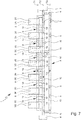
- Fig. 5 shows a schematic representation of another embodiment of the proposed Appendix 1.
- Fig. 5 illustrates that the proposed Appendix 1 can be very easily expanded by integration or integration of other processing equipment 3 - that can be extended.
- further processing devices here at a processing or production line ending with the output station 6 were retrofitted (in Fig. 5 to the left thereof) further processing devices 3, here by way of example a further processing device 3D for polishing and an additional processing device 3G for coating, are integrated.
- the transfer system 4 has been extended accordingly. If necessary, the dispensing station 6 can then also be rebuilt and arranged, for example, at the end, as indicated by dashed lines by position 6 '.
- the proposed Appendix 1 allows optimized processing and utilization of the often different processing capacities of the various processing facilities 3.
- lenses 2 and lens carrier 5 with lenses 2 optionally to the original processing device 3D on the right side or to the further processing device 3D on the left side be promoted, with a forward funding on the second transport track T2 and, if necessary, a return promotion in particular on the third transport track T3, for example for subsequent processing in the right-hand processing device 3F can take place.
- circulation or circulation K of the lenses 2 or lens carriers 5 can take place via the second transport track T2 in one direction and the third transport track T3 in the opposite direction.
- a circulation or circulation K of the lenses 2 or lens carrier 5 is made possible or formed by corresponding transverse connections or cross-conveyances between the two transport tracks T2 and T3. This can in particular enable a storage of lenses 2 or lens carriers 5 and / or prevent or minimize the formation of undesirable congestion.
- the lenses 2 or lens carriers 5 are discharged or conveyed to desired processing devices 3 as required and / or available. This takes place, in particular, by corresponding transverse conveying and / or a change to the first transport track T1 or to a transfer device 9 assigned or arranged upstream of the desired processing device 3.
- a corresponding circulation or circulation K of lenses 2 or lens carriers 5 is in the proposed Appendix 1 according to the in Fig. 6 shown, another embodiment or according to the proposed method preferably also possible or provided.
- Fig. 6 is schematically indicated that circulate in the circulation or circle promotion K several lens carrier 5 or conveyed in a cycle, for example, until the next or a desired processing device 3 for receiving or Zuföd réelle for the appropriate processing is already.
- the extension section is preferably angled.
- the system 1 and the transport lanes T have here therefore in particular an L-shape.
- other particularly polygonal arrangements or even an at least substantially rectilinear arrangement or other arrangements, in particular depending on the structural conditions, are possible.
- the original Appendix 1 with the original processing devices 3A, 3B, 3C, 3D, 3F and 3G (in FIG Fig. 6 above), for example, to additional processing devices 3C, 3D and 3E (in Fig. 6 on the left) added or expanded.
- the extension of the transfer system 4 takes place in the illustrated embodiment, preferably via connecting devices 22, in particular corresponding extensions, deflections, corner connectors and / or the like., Particularly preferably to further conveyors 10 and / or transfer devices 9 o. The like.
- To connect, and / or the first extend second and / or third transport track T.
- the transport lanes T2 and T3 or the possible or preferred circular conveying K are extended accordingly.
- the illustrated example originally ended the circle promotion K and the transport lanes T in the area of the delivery station 6. Only the extension has led here to the exemplary illustrated L-shaped structure.
- the required additional transfer devices 9 or conveyors 10 and / or changing devices 11 when supplementing the transfer system 4 are preferably connected directly to the bus system 13. Accordingly, the effort for the expansion can be minimized, so an extension is very easy.
- the transfer devices 9, conveying devices 10 and / or changing devices 11 are controlled by the preferably central transfer control device 12, in particular a programmable logic controller, and / or via the bus system 13 and that the conveying devices 8 of the processing devices 3 from the respective processing device. 3 or whose machine control 20 are controlled.
- the transfer system 4 is controlled in total by the control device 12. This allows an optimal sequence and / or a very robust, less prone to interference control. Furthermore, this facilitates an extension of the system 1.
- individual, multiple or all processing devices 3 or their machine controls 20 are preferably connected to the central system or system controller 21, for example via a data network, a (further) bus system 25, an Ethernet cabling o.
- the system controller 21 can be a server, a database system or the like.
- the system controller 21 manages the jobs to be executed by the installation 1 or the lenses 2 to be processed by the installation 1 or the information required for the machining, for example, machining data, machining plans or machining sequences, machining stations, planned or required processing steps, optical and / or geometric information or data of the lenses 2 and / or other information, for example on tools to be used or available o.
- the system controller 21 manages the jobs to be executed by the installation 1 or the lenses 2 to be processed by the installation 1 or the information required for the machining, for example, machining data, machining plans or machining sequences, machining stations, planned or required processing steps, optical and / or geometric information or data of the lenses 2 and / or other information, for example on tools to be
- the transfer controller or control device 12 on the one hand and the system controller 21 on the other hand are coupled to each other for information or data exchange, as in Fig. 6 indicated schematically.
- the system controller 21 can control the transfer system 4 or the transfer devices 9, conveyors 10 and / or changing devices 11 in particular via the control device 12 such that desired lenses 2 or lens carriers 5 to the respective processing devices 3, if necessary only on appropriate request of the respective Processing device 3 out to be promoted.
- different or all processing machines 3 can individually request or pick up workpieces or lenses 2 or lens carriers 5 to be processed with lenses 2 from the transfer system 4, perform the respective required processing, and return the lens 2 to the transfer system 4 after processing pass or passed to this.
- a processing device 3 can autonomously determine, in particular taking into account a processing plan and processing status (this processing data or information is queried or provided in particular by the system controller 21 or a database, a data memory or the like) whether one (in particular near or short Lens 2 located in front of the processing device 3 is suitable for processing in the respective processing device 3 in order to request this or the corresponding lens carrier 5 with appropriate capacity of the processing device 3 or to allow it to be conveyed.
- a plurality of processing devices 3 for the same processing can independently select and / or request a lens 2 for the next processing.
- the request is made by a processing device 3 in particular when it has been cleared.
- the request can also be made beforehand to minimize waiting times.
- the respective processing device 3 outputs a corresponding information or a corresponding signal to the control device 12 when a lens 2 or a lens carrier 5 is to be dispensed after the processing to the downstream transfer device 9 or to the transfer system 4 or has already been dispensed.
- the respective lens 2 or the respective lens carrier 5 is then received by the transfer system 4 or the transfer device 9 downstream of the respective processing device 3, for example into the receiving region 19, and / or further conveyed, for example to a downstream processing device 3 and /. or in the second transport track T2 or the circuit promotion K introduced again. This can be done either by the transfer system 4 or its control device 12 independently and / or in coordination and / or in dependence on the system controller 21.
- the processing device 3 ready for receiving a lens 2 or a lens carrier 5 is then conveyed back to a lens 2 or a lens carrier 5, the selection - as already mentioned - being particularly preferred by the respective processing device 3 or its machine control 20 and / or by the system controller 21, particularly preferably taking into account data relevant for the processing, such as the processing plan and the processing state, in particular from the system controller 21.
- the control of the feed is then preferably via the control device 12, but if necessary, can also be controlled by the respective processing device 3 and the machine controller 20, as later with reference to another embodiment according to Fig. 7 explained in more detail.
- a processing device 3 or its conveying device 8 preferably transfers a lens 2 or a lens carrier 5 to the transfer system 4 or to a transfer device 9, preferably downstream of the transfer device F1, if or when there is space to receive it when the respective or associated receiving area 19 is free.
- the processing device 3 or its machine control 20 preferably communicates via the system controller 21 or directly with the transfer control or control device 12 or the transfer system 4 or the respective transfer device 9.
- the delivery takes place, in particular, via the transfer system 4 or the upstream transfer device 9.
- the delivery is preferably triggered by a request from the respective processing device 3 or from the system controller 21, if this has been recognized or communicated that the processing device 3 or its Conveyor 8 has been cleared.
- the conveying devices 8 of the processing devices 3 can in particular also accommodate a plurality of lenses 2 or lens carriers 5 with lenses 2 as required (simultaneously).
- the term “retracting” is accordingly to be understood as meaning that the respective processing device 3 or its delivery device 8 is ready for receiving a lens 2 or a lens carrier 5, even if one or more lenses 2 or lens carrier 5 in the Processing device 3 and its conveyor 8 are located.
- the feed can in particular be effected selectively from the receiving area 19 of an upstream transfer device 9 or through transverse conveyance via the conveyor 15 and subsequent longitudinal conveyance via the conveyor 14 of the upstream transfer device 9, ie by conveyance from the second transport track T2.
- the control device 12 and / or the request of the respective processing device 3 and / or a prioritization of processing or lenses 2 by the system controller 21 controls the process.
- the lens 2, which previously processed the processing device 3, or the lens carrier 5 carrying it, may be produced by the downstream transfer device 9 be recorded and cached if necessary in the receiving area 19. However, if necessary, a further promotion can take place directly without stopping.
- the further promotion may consist in that the lens 2 or the lens carrier 5 is further conveyed to the next processing device 3, ie in the conveying direction F1 further along the first transport track T1, ie the next processing device 3 or its conveyor 8 is conveyed.
- a transverse conveying by means of the conveyor 15 and a change in the second transport track T2 and possibly further in the third transport track T3 done.
- a further promotion to another processing device 3 or possibly to the dispensing station 6 can take place.
- Fig. 7 shows a schematic representation of yet another embodiment of the proposed plant 1.
- Both conveyors 15 and 15 'of a transfer device 9 are preferably operable independently of each other. This makes it possible for the respective processing device 3 to control the upstream transverse conveying via the upstream conveying device 15 and the downstream transverse conveying via the downstream conveying device 15 'directly or independently, in particular independently of the in Fig.
- the associated or arranged therebetween conveyor 14 is optionally provided, so may also be omitted, and is preferably controlled by the upstream or downstream processing device 3 and the machine controller 20.
- a detection of lenses 2 or lens carriers 5 is particularly preferably made possible by sensors 16 which are also connected in particular to the machine control 20.
- sensors 16 it is possible, for example, to identify lenses 2 or lens carriers 5 located in the transport track T2 or circulation or circulation conveyor K and to dispose of suitable lenses 2 or lens carriers 5 for processing in the respective processing device 3 or into the first Leave transport track T2 change, in particular independently of other processing devices 3 and their machine control 20 and / or independent of the transfer control or control device 12 and / or independent of the system controller 21st
- the machine controller 20 are preferably associated with the respective processing device 3 or arranged in this, but can also be separated therefrom or arranged centrally.
- Fig. 8 shows a schematic representation of another embodiment of the proposed plant 1.
- this embodiment preferably at least a substantially U-shaped arrangement, in particular the first or second transport track T1 or T2 is formed.
- two groups or rows of processing devices here for example a first group of processing devices 3A, 3B and 3C and a second group of processing devices 3D, 3E and 3F, are formed or arranged opposite one another and / or with conveying devices 8 arranged on mutually facing sides and / or arranged such that the associated transport tracks T1 and / or T2 of the two groups are preferably parallel to each other.
- the system 1 or the transfer system 4 has a transverse connection of the two groups of processing devices 3 via a conveyor 10 'and / or 10 "transversely or interconnected.
- the conveyor 10 forms a leg or portion of the preferably at least substantially U-shaped arrangement or a part the preferably substantially U-shaped course of the first or second transport track T1 or T2, here the second transport track T2.
- one or more processing devices 3 can be arranged at this section.
- the system 1 or the transfer system 4 has a return line R on.
- the return conveyor R preferably has the (second) conveyor 10 "or is formed thereby.
- a circle promotion or circulation particularly preferably via the first or second transport track T1 or T2 possible.
- this is the return line R for the first or second transport track T1 or T2 (in the illustrated embodiment, only for the second transport track T2) provided.
- the return conveyor R allows a return conveyance in the return direction FR, so that a circulation or circulation of the lenses 2 or lens carrier 5 is made possible via the second transport track T2 without reversing the conveying direction F2 and without change in the opposite direction F3.
- the system 1 or the transfer system 4 preferably has a receiving station 7 and / or delivery station 6 or corresponding conveyor devices 10 (in Fig. 8 dashed lines indicated on the left side) as an inlet and / or outlet for lenses 2 and 5 lens carrier.
- the return conveyor R or conveyor 10 is particularly preferably arranged in the region of the beginning and / or end of the transport track T1 or T2 and / or the usual processing and / or in the region of the receiving station 7 or discharge station 6.
- Particularly preferred is the return line R or conveyor 10 "connected via appropriate switches.
- other constructive solutions and / or arrangements are possible, in particular depending on the location and training or arrangement of the receiving station 7 and / or dispensing station. 6
- Fig. 8 allows the return line R a circle promotion or circulation of the lenses 2 and Linsenvic 5. Accordingly, a third transport track T3 for return promotion or circulation is not required. However, the return link R and the third transport lane If necessary, T3 can also be combined or used in addition, in particular depending on the structural conditions and / or existing processing facilities 3.
- the return conveyor connection R can also be arranged at a different location or form only one circuit for some of the processing devices 3, for example connected between the processing device 3B and 3C on the one hand and between the processing device 3D and 3E on the other hand form or enable shorter or smaller circulation.
- the system 1 or the transfer system 4 conveyors 23 for curve promotion in particular to straight sections of the respective transport track, here T2, and / or various conveyors 10, 10 'and / or 10 "and / or the return line R with the transport track
- the curve promotion can be achieved that the alignment of the lenses 2 and lens carrier 5 with respect to the respective conveying direction F remains the same so for example in a lens carrier 5 with two lenses 2 always the same lens 2 front.
- the two groups of processing devices 3 and the two legs of the particularly preferred U-shaped arrangement are preferably arranged relatively close to each other in the illustrated embodiment and / or spaced so that the gap forms an access option for an operator, not shown.
- the cross connections or conveying devices 10 'and / or 10 are designed such that they can be loosened or opened or folded away as needed Alternatively or additionally, these can also be raised or lowered and connected, for example, via corresponding vertical conveyors or downgrades that a preferably free access to the gap is made possible.
- the intermediate space can also be used for resource containers for processing devices 3, for example for a coolant container, a container for chips, a container for cooling liquid or the like.
- the containers can in particular in the space and / or below the transfer system, particularly preferably be arranged below the second transport track T2.
- Fig. 9 shows in a very schematic representation of a block diagram of a preferred control structure of a proposed Appendix 1.
- the system 1 or the transfer system 4 preferably has an in particular central transfer or control device 12.
- This is in particular a so-called band master computer. If necessary, it can also be a program and / or multiple networked computers, computers, controllers o. The like. Act.
- the transfer or control device 12 serves, in particular, for controlling the production flow or the conveyance of the lenses 2 or lens carriers 5, such as circulation or circulation and / or delivery of lenses 2 or lens carriers 5 to processing devices 3 and away from them.
- the control device 12 particularly preferably controls the transfer devices 9, conveying devices 10 and / or changing devices 11, conveying devices 14 for longitudinal conveying, conveying devices 15 for transverse conveying and / or stopping devices 18, the transfer devices 9 preferably additionally or alternatively also by the processing devices 3 or their machine control 20 - in particular when connected to the bus system 13 - (direct) can be controlled.
- the system or system controller 21 is preferably coupled or connected via a (further) bus system 25 to the processing devices 3 or their machine controllers 20.
- a (further) bus system 25 to the processing devices 3 or their machine controllers 20.
- other types of connection are possible here as well.
- the controller 12 may also be connected to the system controller 21 via the bus system 25 or a separate connection for data exchange.
- the system controller 21 preferably forms a lens management system.
- the system controller 21 serves, in particular, for the acceptance or recording of orders O and / or the administration of orders, production data and / or lens blanks and / or the provision of interfaces to other systems, For example, to systems or modules for the lens design that determine the desired geometric shape of lenses 2 and / or the required processing or processing steps, in particular depending on desired optical properties.
- production data P which in particular provide, manage and / or maintain processing plans (processing steps and / or orders or sequences) and processing statuses (processing conditions or information on processes to be executed next), and / or generate.
- the production data P are made available in particular by the system controller 21 to the processing devices 3 or their machine controls 20 and / or can be queried by them, as indicated by a corresponding arrow in FIG Fig. 9 indicated schematically.
- the system 26 serves, in particular, for the visualization and / or management of machine states, that is to say states of the processing devices 3, production data, process data and / or other information.
- system 26 preferably serves the management of macros and / or reporting.
- the system 26 may be appropriate programs, applications o. The like. And / or one or more computers, such as a server o. The like., Act. The same applies to the system controller 21 and / or control device 12.
- the processing devices 3 or their machine controllers 20 may preferably further information I, such as process data u. Like. Communicate to the system 26, as indicated by a corresponding arrow in Fig. 9 indicated.
- system 26 may also be connected to the bus system 25.
- data exchange can also take place via the system controller 21.
- the system controller 21 and the system 26 may have production data P and / or data status information S, such as order status, as indicated by arrow P / S in FIG Fig. 9 indicated, exchange.
- production data P and / or data status information S such as order status, as indicated by arrow P / S in FIG Fig. 9 indicated, exchange.
- the system controller 21 and the controller 12 may have production data P as indicated by a corresponding arrow in FIG Fig. 9 indicated, and / or status information S, in particular data on the order status, as indicated by a corresponding arrow A in Fig. 9 indicated, exchange and / or adjust.
- control device 12 is preferably also connected to the further bus system 25 and / or in any other way or connected to the data exchange or connectable.
- the processing devices 3 or their machine controllers 20 may preferably have order information A, such as information on the status, in particular order status, requests and / or requests, as indicated by a corresponding arrow in FIG Fig. 9 indicated, exchange.
- order information A can be transmitted to the control device 12 or communicated to the control device 12 and / or a request for a lens 2 or a lens carrier 5 can be transmitted to the control device 12.
- information about lenses 2 or lens carriers 5 which are preferably detected or identified by the sensors 16 can be transmitted from the sensors 16 directly or via the control device 12 to individual or multiple or all processing devices 3 or their machine control 20.
- This information exchange takes place, in particular, in the context of the requirement of new lenses 2 or lens carriers 5 by the processing devices 3, as indicated by the double arrow A in FIG Fig. 9 indicated.
- This information exchange can also take place taking into account further data or information, in particular of process data P, particularly preferably processing plans and processing stations, which are preferably provided by the system controller 21.
- the processing devices 3 can preferably independently select and / or request new orders or lenses 2 for processing. This allows, according to a particularly preferred aspect, a quasi-arbitrary or independent latching or insertion of processing equipment 3 in the Appendix 1.
- the proposed Appendix 1 and the proposed method for processing optical lenses 2 is very flexible. In particular, an improved or optimized utilization of processing capacities can be achieved. Furthermore, a very flexible processing and adaptation to different circumstances is possible. For example, downtimes or failures of individual processing devices 3 can be compensated very easily and / or optimally, in particular if other or alternative processing devices 3 are available. Alternatively or additionally, an intelligent center of gravity control can take place, for example in such a way that a processing device 3 which is particularly suitable for a particular processing is used primarily for this processing, that is, for example, a lathe with a particularly large chip space for processing particularly long or bulky chips during machining Lenses 2.
- the proposed Appendix 1 and the proposed method allow in particular a very large flexibility also in the processing of lenses 2 with different shapes and / or different materials.
- the usual processing or production lines can be avoided, which are primarily aligned to the processing of lenses 2 made of a particular material or lenses 2 of a particular shape.
Description
Die vorliegende Erfindung betrifft eine Anlage zur Bearbeitung optischer Linsen sowie ein Verfahren zum Bearbeiten optischer Linsen.The present invention relates to a system for processing optical lenses and a method for processing optical lenses.
Die Bearbeitung von optischen Linsen erfolgt in mehreren Schritten bzw. in mehreren separaten Bearbeitungseinrichtungen. Die Bearbeitung kann insbesondere eine formgebende oder spanende Bearbeitung, ein Polieren, ein Beschichten, ein Prüfen bzw. Messen, ein Markieren, ein Beschichten und/oder ein Reinigen umfassen.The processing of optical lenses takes place in several steps or in several separate processing facilities. The machining may in particular comprise shaping or machining, polishing, coating, testing, marking, coating and / or cleaning.
Es ist grundsätzlich bekannt, Transfersysteme zum Transport von Werkstücken, insbesondere von Werkstückträgern mit den Werkstücken, zu und von Bearbeitungseinrichtungen einzusetzen.It is basically known to use transfer systems for transporting workpieces, in particular workpiece carriers with the workpieces, to and from processing facilities.
Die
Die
Die
Die
Die
Die
Die
Die
Die
Bei der Linsenbearbeitung ist es bisher üblich, eine Bearbeitungslinie aus mehreren Bearbeitungseinrichtungen zu bilden, die von den zu bearbeitenden Linsen nacheinander durchlaufen werden. Die Bearbeitungslinie wird dann insbesondere auf eine bestimme Bearbeitung oder Linsenform eingestellt. Für verschiedene Bearbeitungen, beispielsweise unterschiedlich zu bearbeitende Linsen, muss entweder eine Umrüstung erfolgen oder wird eine separate Bearbeitungslinie eingesetzt. Bei der Bearbeitung unterschiedlicher Linsen kann dies zur Folge haben, dass eine sehr ungleichmäßige Auslastung verschiedener Bearbeitungslinien erfolgt oder dass eine häufige Umrüstung erforderlich ist. Das aufeinanderfolgende bzw. lineare Durchlaufen einer vorgegebenen Folge von Bearbeitungseinrichtungen hat den Nachteil, dass bei Ausfall einer Bearbeitungseinrichtung die Bearbeitung insgesamt angehalten werden muss. Weiter ist eine optimale Auslastung von verschiedenen Bearbeitungseinrichtungen, insbesondere wenn diese unterschiedliche Bearbeitungskapazitäten haben, in den üblichen Bearbeitungslinien nicht möglich. Üblicherweise werden alle Bearbeitungseinrichtungen und Fördereinrichtungen von einer zentralen Steuerung gesteuert. Insbesondere wird üblicherweise zentral festqelegt, welche Bearbeitungseinrichtung welche Linse in welcher Form bearbeitet. Bei bestehenden Bearbeitungslinien ist eine Erweiterung daher bisher sehr aufwendig. Üblicherweise müssen dann ein kompletter Umbau und eine Neuprogrammierung der zentralen Steuerung erfolgen.In the processing of lenses, it has hitherto been customary to form a processing line from a plurality of processing devices, which are passed through in succession by the lenses to be processed. The processing line is then adjusted in particular to a specific processing or lens shape. For different processing, for example, different lenses to be processed, either a conversion must be done or a separate processing line is used. When processing different lenses, this can result in a very uneven utilization of different processing lines or that a frequent conversion is required. The successive or linear running through a predetermined sequence of processing devices has the disadvantage that in case of failure of a processing device, the processing must be stopped altogether. Next is an optimal utilization of different processing facilities, especially if they have different processing capacities, not possible in the usual processing lines. Usually, all processing facilities and conveyors of a controlled central control. In particular, it is usually determined centrally which processing device processes which lens in which form. For existing processing lines an extension is therefore so far very complicated. Usually then a complete conversion and reprogramming of the central control must be done.
Der vorliegenden Erfindung liegt die Aufgabe zugrunde, eine Anlage zur Bearbeitung optischer Linsen sowie ein Verfahren zum Bearbeiten optischer Linsen anzugeben, wobei eine optimierte Bearbeitung und Handhabung bei hoher Flexibilität und/oder geringem Platzbedarf insbesondere auch unter Berücksichtigung unterschiedlicher Bearbeitungsgeschwindigkeiten oder Kapazitäten von unterschiedlichen Bearbeitungseinrichtungen ermöglicht wird bzw. werden, insbesondere wobei eine Erweiterung der Anlage sehr einfach möglich ist.The present invention has for its object to provide a system for processing optical lenses and a method for processing optical lenses, wherein an optimized processing and handling with high flexibility and / or small footprint, especially taking into account different processing speeds or capacities of different processing facilities is possible or be, in particular wherein an extension of the system is very easy.
Die obige Aufgabe wird durch eine Anlage gemäß Anspruch 1 oder ein Verfahren gemäß Anspruch 7 gelöst. Vorteilhafte Weiterbildungen sind Gegenstand der Unteransprüche.The above object is achieved by a system according to
Gemäß einem Aspekt der vorliegenden Erfindung weist ein Transfersystem der Anlage vorzugsweise eine Rückförderverbindung zur Rückförderung bzw. Zirkulation von Linsen bzw. Linsenträgern auf. Die Rückförderverbindung verbindet insbesondere eine erste oder zweite Transportspur, besonders bevorzugt im Bereich des Anfangs und Endes und/oder zur Bildung eines Kreislaufs bzw. der Möglichkeit zur Kreisförderung bzw. Zirkulation.According to one aspect of the present invention, a transfer system of the system preferably has a return connection for the return or circulation of lenses or lens carriers. The return conveyor connection in particular connects a first or second transport track, particularly preferably in the region of the beginning and end and / or to form a circuit or the possibility for circulation or circulation.
Gemäß einem weiteren Aspekt der vorliegenden Erfindung ist jeder Bearbeitungseinrichtung eine eigene Fördereinrichtung zugeordnet. Zwischen den verschiedenen Bearbeitungseinrichtungen mit den zugeordneten Fördereinrichtungen sind jeweils Transfereinrichtungen angeordnet. Die Transfereinrichtungen und die Fördereinrichtungen der Bearbeitungseinrichtungen bilden eine erste, insbesondere zumindest im wesentlichen geradlinig verlaufende Transportspur. Die Transfereinrichtungen sind zur Aufnahme und temporären Zwischenspeicherung und zur bedarfsweisen Weiterförderung mindestens einer Linse oder eines Linsenträgers wahlweise an eine nachfolgende Bearbeitungseinrichtung bzw. Fördereinrichtung oder an eine zweite Transportspur ausgebildet. So werden ein kompakter Aufbau und eine flexible Bearbeitung ermöglicht.According to a further aspect of the present invention, each processing device is assigned its own conveying device. Between the various processing devices with the associated conveyors each transfer devices are arranged. The transfer devices and the conveying devices of the processing devices form a first, in particular at least substantially rectilinear, transport track. The transfer devices are designed for receiving and temporary buffering and for further conveying on demand of at least one lens or lens carrier optionally to a subsequent processing device or conveying device or to a second transport track. This enables a compact design and flexible processing.
Gemäß einem weiteren Aspekt der vorliegenden Erfindung ist die einer Bearbeitungseinrichtung zugeordnete Fördereinrichtung in die jeweilige Bearbeitungseinrichtung integriert und/oder an diese (fest) angebaut. Besonders bevorzugt endet die jeweilige Fördereinrichtung zumindest im wesentlichen in der Flucht oder Verlängerung einer Seite der Bearbeitungseinrichtung. Die Länge der Fördereinrichtung entspricht vorzugsweise zumindest im wesentlichen der Breite der jeweiligen Bearbeitungseinrichtung. Dies ist einem kompakten Aufbau insbesondere einer Anlage mit mehreren Bearbeitungseinrichtungen zuträglich.According to a further aspect of the present invention, the conveying device assigned to a processing device is in the respective processing device integrated and / or attached to these (fixed). Particularly preferably, the respective conveyor ends at least substantially in the alignment or extension of one side of the processing device. The length of the conveyor preferably corresponds at least substantially to the width of the respective processing device. This is conducive to a compact design, in particular a system with multiple processing facilities.
Die Transfereinrichtungen zwischen den Bearbeitungseinrichtungen ermöglichen, dass nach erfolgter Bearbeitung einer Linse oder eines Linsenpaares eine Bearbeitungseinrichtung bzw. die der Bearbeitungseinrichtung zugeordnete Fördereinrichtung wieder frei gefahren werden kann. Eine bearbeitete Linse bzw. ein Linsenträger mit mindestens einer bearbeiteten Linse kann nämlich an die nachgeordnete Transfereinrichtung weiter gefördert werden. Diese nimmt die bearbeitete Linse bzw. den Linsenträger auf, so dass nun die Bearbeitungseinrichtung und deren Fördereinrichtung frei sind, um die nächste Linse bzw. den nächsten Linsenträger von einem Transfersystem, insbesondere einer vorgeordneten Transfereinrichtung, aufzunehmen. Hierdurch können Leerlaufzeiten minimiert und damit eine optimierte Ausnutzung bzw. ein optimierter Durchsatz erreicht werden.The transfer devices between the processing devices make it possible, once a lens or a pair of lenses has been processed, to move a processing device or the conveying device associated with the processing device freely again. A processed lens or a lens carrier with at least one processed lens can namely be further conveyed to the downstream transfer device. This takes up the processed lens or the lens carrier, so that now the processing device and its conveyor are free to receive the next lens or the next lens carrier of a transfer system, in particular a upstream transfer device. As a result, idle times can be minimized and thus optimized utilization or optimized throughput can be achieved.
Insbesondere sind die Transfereinrichtungen und die Fördereinrichtungen der Bearbeitungseinrichtungen zur unabhängigen Förderung der Linsen bzw. Linsenträger unabhängig steuerbar bzw. antreibbar. Je nach erforderlicher Bearbeitung können die Fördereinrichtungen die jeweilige Linse bzw. den jeweiligen Linsenträger beispielsweise anhalten, vorwärts bewegen oder bedarfsweise sogar rückwärts bewegen. Dies ermöglicht eine sehr hohe Flexibilität bei der Bearbeitung. Gleichwohl wird aus den Fördereinrichtungen der Bearbeitungseinrichtungen und den Transfereinrichtungen gemäß der vorliegenden Erfindung vorzugsweise eine geradlinige und/oder durchgehende (erste) Transportspur für die Linsen bzw. Linsenträger gebildet. Dies gestattet einen kompakten Aufbau.In particular, the transfer devices and the conveying devices of the processing devices for independently conveying the lenses or lens carriers are independently controllable or drivable. Depending on the required processing, the conveyors can, for example, stop the respective lens or the respective lens carrier, move it forward or, if necessary, even move it backwards. This allows a very high flexibility in the processing. However, preferably a rectilinear and / or continuous (first) transport track for the lenses or lens carriers is formed from the conveyors of the processing devices and the transfer devices according to the present invention. This allows a compact construction.
Die Transfereinrichtungen sind vorzugsweise zur wahlweisen Weiterförderung an eine nachfolgende Fördereinrichtung bzw. Bearbeitungseinrichtung oder an die zweite Transportspur ausgebildet, bilden also jeweils vorzugsweise eine Weiche. Die Transfereinrichtungen gestatten also vorzugsweise einen Wechsel von der ersten Transportspur zur zweiten Transportspur. Insbesondere gestatten die Transfereinrichtungen aber auch einen umgekehrten Wechsel von der zweiten Transportspur zur ersten Transportspur. Dies gestattet einen einfachen Aufbau und einen sehr flexiblen Ablauf, da Linsen bzw. Linsenträger je nach Bedarf zwischen den Transportspuren wechseln können. Die zweite Transportspur kann insbesondere als Umgehungsspur eingesetzt werden, um einzelne Bearbeitungseinrichtungen umgehen zu können.The transfer devices are preferably designed for selective further conveyance to a subsequent conveying device or processing device or to the second transport track, thus in each case preferably form a switch. The transfer devices thus preferably allow a change from the first transport track to the second transport track. In particular, however, the transfer devices also allow a reverse change from the second transport track to the first transport track. This allows a simple structure and a very flexible process, since lenses or lens wearer can switch between the transport tracks as needed. The second transport track can in particular be used as a bypass track to handle individual processing facilities.
Die zweite Transportspur verläuft vorzugsweise parallel zu der ersten Transportspur und/oder zumindest im wesentlichen geradlinig.The second transport track preferably runs parallel to the first transport track and / or at least substantially rectilinearly.
Die zweite Transportspur ist vorzugsweise unabhängig von der ersten Transportspur steuerbar.The second transport track is preferably controllable independently of the first transport track.
Die zweite Transportspur ist vorzugsweise aus mehreren, insbesondere unabhängig von einander steuerbaren bzw. antreibbaren Fördereinrichtungen aufgebaut, die hintereinander mit ggfs. dazwischen angeordneten Transfereinrichtungen oder Wechseleinrichtungen die zweite Transportspur bilden. Dies gestattet eine optimierte Förderung, wobei insbesondere Linsen oder Linsenträger auf einer Fördereinrichtung der zweiten Transportspur unabhängig von der Förderung anderer Linsen oder Linsenträger auf einer anderen Fördereinrichtung der zweiten Transportspur förderbar bzw. transportierbar sind.The second transport track is preferably constructed of a plurality of conveyors which can be controlled or driven independently of one another and which form the second transport track one behind the other with transfer devices or changing devices arranged therebetween. This allows optimized delivery, wherein in particular lenses or lens carriers can be conveyed or transported on a conveying device of the second transport track independently of the conveyance of other lenses or lens carriers on another conveying device of the second transport track.
Vorzugsweise weisen die Transfereinrichtungen jeweils einen Aufnahmebereich zur temporären Zwischenspeicherung von mindestens einer Linse oder mindestens einem Linsenträger auf. So kann eine Aufnahme und Zwischenspeicherung einer Linse bzw. eines Linsenträgers nach vorheriger Bearbeitung in einer Bearbeitungseinrichtung erfolgen. Wahlweise kann die Linse bzw. der Linsenträger zu gegebener Zeit an eine andere Bearbeitungseinrichtung oder an eine andere Transortspur oder Fördereinrichtung des Transfersystems weitergeleitet bzw. weitergefördert werden. Alternativ oder zusätzlich kann diese Aufnahme bzw. Zwischenspeicherung auch dazu dienen, dass eine andere Linse oder ein anderer Linsenträger durch entsprechende Querförderung zusätzlich von der Transfereinrichtung aufgenommen und an eine nachgeordnete Bearbeitungseinrichtung bzw. deren Fördereinrichtung (zuerst) weitergeleitet bzw. weitergefördert werden kann. Nachfolgend kann die Linse bzw. der Linsenträger aus dem Aufnahmebereich dann wahlweise an die nachgeordnete Bearbeitungseinrichtung oder an eine andere Fördereinrichtung bzw. Transportspur weitergeleitet bzw. weitergefördert werden. Dementsprechend wird eine sehr flexible und bedarfsgerechte Bearbeitung ermöglicht.Preferably, the transfer devices each have a receiving area for the temporary buffering of at least one lens or at least one lens carrier. Thus, a recording and intermediate storage of a lens or a lens carrier after prior processing in a processing device. Optionally, the lens or the lens carrier can be forwarded or forwarded in due course to another processing device or to another transport track or conveying device of the transfer system. Alternatively or additionally, this recording or temporary storage can also serve to additionally receive a different lens or another lens carrier from the transfer device by appropriate transverse conveyance and forward it (first) to a downstream processing device or its delivery device. Subsequently, the lens or the lens carrier from the receiving area can then either be forwarded to the downstream processing device or to another conveyor or transport track or further promoted. Accordingly, a very flexible and needs-based processing is possible.
Besonders bevorzugt bilden die Transfereinrichtungen bzw. deren Aufnahmebereich entsprechende Aufnahmepuffer für Linsen bzw. Linsenträger. Hierdurch ist es beispielsweise möglich, dass andere Fördereinrichtungen bzw. eine zweite Transportspur oder weitere Transportspuren des Transfersystems zumindest im Wesentlichen kontinuierlich fördern können. Dies ermöglicht eine wesentliche Vereinfachung der Steuerung.The transfer devices or their receiving area particularly preferably form corresponding receiving buffers for lenses or lens carriers. This makes it possible, for example, that other conveying devices or a second transport track or further transport tracks of the transfer system, at least substantially can continuously promote. This allows a substantial simplification of the control.
Die zweite Transportspur und entsprechende Verbindungen oder Querfördereinrichtungen zwischen der ersten und zweiten Transportspur, besonders bevorzugt zwischen jeder Bearbeitungseinrichtung, ermöglichen ein bedarfsweises Überholen von Linsen bzw. Linsenträgern, beispielsweise für eine Bearbeitung von Linsen mit besonderer Priorität, und/oder ein Umgehen oder Auswählen von bestimmten Bearbeitungen bzw. Bearbeitungseinrichtungen. Beispielsweise kann eine Linse aus Polykarbonat an eine hierfür besonders geeignete bzw. eingerichtete Bearbeitungseinrichtung gefördert werden, während eine aus einem anderen Material, beispielsweise CR 39, bestehende Linse an eine andere, hierfür geeignete bzw. eingerichtete Bearbeitungseinrichtung gefördert werden kann.The second transport track and corresponding connections or cross-conveyor devices between the first and second transport track, particularly preferably between each processing device, allow overtaking of lenses or lens carriers, for example, for processing lenses with special priority, and / or bypassing or selecting particular Machining or processing facilities. For example, a lens made of polycarbonate can be conveyed to a processing device which is particularly suitable or set up for this purpose, while a lens made of another material, for example CR 39, can be conveyed to another processing device which is suitable or equipped for this purpose.
Gemäß einem bevorzugten Aspekt der vorliegenden Erfindung ist die Förderrichtung der zweiten Transportspur und/oder der Transfereinrichtungen und/oder der Fördereinrichtungen der Bearbeitungseinrichtungen umkehrbar. Dies gestattet einen kompakten Aufbau und eine hohe Flexibilität bei der Bearbeitung.According to a preferred aspect of the present invention, the conveying direction of the second transport track and / or the transfer devices and / or the conveying devices of the processing devices is reversible. This allows a compact design and high flexibility in the processing.
Gemäß einem weiteren Aspekt der vorliegenden Erfindung weist das Transfersystem vorzugsweise zusätzlich eine dritte Transportspur zur parallelen Förderung, insbesondere Rückförderung, von Linsen oder Linsenträgern auf. Insbesondere weisen die zweite und dritte Transportspur zueinander entgegengesetzte Förderrichtungen auf. Die dritte Transportspur verläuft vorzugsweise ebenfalls zumindest im wesentlichen gradlinig und/oder parallel zu den anderen Transportspuren. Dies gestattet einen kompakten Aufbau und eine optimierte Förderung und damit eine optimierte Bearbeitung und Auslastung von Bearbeitungsmaschinen.According to a further aspect of the present invention, the transfer system preferably additionally has a third transport track for the parallel conveyance, in particular return conveyance, of lenses or lens carriers. In particular, the second and third transport tracks have opposite conveying directions to one another. The third transport track also preferably runs at least substantially rectilinearly and / or parallel to the other transport tracks. This allows a compact design and optimized delivery and thus optimized processing and utilization of processing machines.
Die dritte Transportspur ist vorzugsweise ähnlich oder entsprechend wie die zweite Transportspur aufgebaut. Vorzugsweise ist die dritte Transportspur aus mehreren hintereinander bzw. in Serie angeordneten Fördereinrichtungen mit bedarfsweise dazwischen angeordneten Transfer- oder Wechseleinrichtungen aufgebaut. Die Fördereinrichtungen sind vorzugsweise wieder zur unabhängigen Förderung von Linsen bzw. Linsenträgern unabhängig voneinander steuerbar.The third transport track is preferably similar or constructed as the second transport track. Preferably, the third transport track of a plurality of successively arranged or in series conveyors is constructed with, if necessary, arranged therebetween transfer or change devices. The conveyors are preferably again independently for the independent promotion of lenses or lens carriers controllable.
Vorzugsweise sind Wechseleinrichtungen zum Wechseln zwischen der zweiten und dritten Transportspur bzw. den Transportspuren vorgesehen. Die Wechseleinrichtungen können von den Transfereinrichtungen gebildet oder davon getrennt bzw. unabhängig sein.Preferably changing devices are provided for changing between the second and third transport track or the transport tracks. The changing devices may be formed by, or separate from, the transfer devices.
Die Wechseleinrichtungen weisen vorzugsweise Fördereinrichtungen zur Querförderung mindestens einer Linse oder eines Linsenträgers zum Wechseln zwischen zweiter und dritter Transportspur bzw. den Transportspuren auf.The changing devices preferably have conveying devices for transversely conveying at least one lens or lens carrier for changing between the second and the third transport track or the transport tracks.
Mittels der zweiten Transportspur in Verbindung mit der dritten Transportspur und/oder Rückförderverbindung ist es insbesondere möglich, einzelne, mehrere oder alle Bearbeitungseinrichtungen wiederholt und/oder in beliebiger Reihenfolge anzufahren, insbesondere also die Reihenfolge der Bearbeitungen zu variieren bzw. beliebig zu wählen, die Auslastung der Bearbeitungseinrichtungen zu variieren bzw. zu optimieren und/oder die Bearbeitungsabläufe zu optimieren.By means of the second transport lane in conjunction with the third transport lane and / or return conveyor connection, it is possible, in particular, to approach individual, multiple or all processing devices repeatedly and / or in any desired order, in particular to vary the order of processing or to select any desired utilization to vary or optimize the processing facilities and / or to optimize the machining processes.
Die Möglichkeit der Rückförderung durch Umkehr der Förderrichtung und/oder über die dritte Transportspur bzw. über die Rückförderverbindung vereinfacht insbesondere eine Erweiterung der vorschlagsgemäßen Anlage. Weitere Bearbeitungseinrichtungen können nämlich einfach am Ende der Anlage bzw. Transportspuren über entsprechende Verlängerungen der Transportspuren angeschlossen werden. So kann beispielsweise die Kapazität für bestimmte Bearbeitungen je nach Bedarf durch entsprechende zusätzliche Bearbeitungseinrichtungen erhöht werden. Diese zusätzlichen Bearbeitungseinrichtungen können dann über die Transportspuren bedarfsgerecht mit den Linsen bzw. Linsenträgern versorgt bzw. angefahren werden. Zwischen den zusätzlichen Bearbeitungseinrichtungen werden dann vorzugsweise wiederum die vorschlagsgemäßen Transfereinrichtungen angeordnet. Nach erfolgter Bearbeitung in einer zusätzlichen Bearbeitungseinrichtung kann je nach Bedarf eine Rückförderung, beispielsweise für eine weitere Bearbeitung oder zur Ausgabe, beispielsweise an einer Abgabestation der ursprünglichen Anlage, erfolgen. Folglich ist kein Umbau oder ein nur geringer Umbau der ursprünglichen Anlage bei einer Erweiterung erforderlich. Dementsprechend wird eine sehr einfache, schnelle und kostengünstige Erweiterung der vorschlagsgemäßen Anlage ermöglicht.The possibility of return conveyance by reversing the conveying direction and / or via the third transport track or via the return conveyor connection simplifies in particular an extension of the proposed system. In fact, further processing devices can simply be connected at the end of the system or transport tracks via corresponding extensions of the transport tracks. For example, the capacity for certain operations can be increased as needed by appropriate additional processing facilities. These additional processing devices can then be supplied or approached via the transport tracks as needed with the lenses or lens carriers. The proposed transfer devices are then preferably again arranged between the additional processing devices. After processing in an additional processing device can be as required, a return promotion, for example, for further processing or output, for example, at a dispensing station of the original system done. Consequently, no conversion or only a small conversion of the original system in an extension is required. Accordingly, a very simple, fast and cost-effective extension of the proposed system is made possible.
Gemäß einem besonders bevorzugten Aspekt der vorliegenden Erfindung werden die Linsen bzw. Linsenträger zirkuliert bzw. in einem Kreislauf gefördert, insbesondere um diese zwischenzulagern und/oder Stauungen vor Bearbeitungseinrichtungen zu vermeiden. Dies erfolgt vorzugsweise in der zweiten Transportspur in einer Richtung und in der dritten Transportspur in entgegengesetzter Richtung, wobei entsprechende Querförderungen oder Querverbindungen zwischen diesen beiden Transportspuren benutzt werden, um die gewünschte Zirkulation bzw. Kreislaufförderung zu ermöglichen. So können diese Transportspuren zur Speicherung bzw. Zwischenspeicherung der Linsen bzw. Linsenträger verwendet werden. Alternativ oder zusätzlich können hierdurch unerwünschte Stauungen vermieden werden. Insbesondere werden Linsen bzw. Linsenträger aus dem Kreislauf bzw. aus der Zirkulation ausgeschleust, wenn eine gewünschte Bearbeitungseinrichtung zur Verfügung steht. Das Ausschleusen erfolgt insbesondere über eine entsprechende Querförderung und/oder durch einen Wechsel in die erste Transportspur bzw. durch einen Wechsel zu einer der gewünschten Bearbeitungseinrichtung zugeordneten oder vorgeordneten Transfereinrichtung.According to a particularly preferred aspect of the present invention, the lenses or lens carriers are circulated or conveyed in a cycle, in particular in order to temporarily store them and / or to avoid stagnation in front of processing devices. This is preferably done in the second transport track in one direction and in the third transport track in the opposite direction, with corresponding cross conveyors or cross connections between these two transport tracks are used to allow the desired circulation or circulation promotion. So these transport tracks for storage or Caching the lenses or lens wearer can be used. Alternatively or additionally, unwanted congestion can thereby be avoided. In particular, lenses or lens carriers are removed from the circulation or from the circulation if a desired processing device is available. The discharging takes place, in particular, via a corresponding transverse conveying and / or by a change in the first transport track or by a change to a transfer device assigned or arranged upstream of the desired processing device.
Die Transfereinrichtungen weisen vorzugsweise jeweils eine Fördereinrichtung zur Längsförderung mindestens einer Linse oder eines Linsenträgers parallel zu einer der Transportspuren und zusätzlich eine Fördereinrichtung zur Querförderung mindestens einer Linse oder eines Linsenträgers zum Wechseln der Transportspur auf. Diese Fördereinrichtungen sind vorzugsweise unabhängig voneinander steuerbar. Dies gestattet eine optimale Förderung, wobei insbesondere die bevorzugte temporäre Aufnahme bzw. Zwischenspeicherung mindestens einer Linse oder Linsenträgers insbesondere auf der Fördereinrichtung zur Längsförderung - besonders bevorzugt in einem Aufnahmebereich vor bzw. stromauf der zugeordneten Fördereinrichtung zur Querförderung - erfolgt, wobei die Fördereinrichtung zur Längsförderung dann ausreichend lang ausgebildet ist.The transfer devices preferably each have a conveying device for the longitudinal conveying of at least one lens or lens carrier parallel to one of the transport tracks and additionally a conveying device for the transverse conveying of at least one lens or a lens carrier for changing the transport track. These conveyors are preferably independently controllable. This allows optimal promotion, wherein in particular the preferred temporary recording or intermediate storage of at least one lens or lens carrier, in particular on the conveyor for longitudinal conveying - particularly preferably in a receiving area before or upstream of the associated conveyor for transverse conveying - takes place, wherein the conveyor for longitudinal promotion then is formed sufficiently long.
Die Fördereinrichtungen zur Querförderung der Transfereinrichtungen bzw. Wechseleinrichtungen oder Teile bzw. Abschnitte davon sind vorzugsweise mittels zugeordneter Hubeinrichtungen wahlweise anhebbar und absenkbar. So kann auf sehr einfache Weise die Querförderung bedarfsweise dann zum Einsatz gebracht werden, wenn diese auch tatsächlich gebraucht wird. Dies gilt insbesondere, wenn die Fördereinrichtungen als Band- oder Gurtförderer ausgebildet sind.The conveying devices for the transverse conveying of the transfer devices or exchangeable devices or parts or sections thereof are preferably selectively raised and lowered by means of associated lifting devices. Thus, in a very simple way, the cross-promotion can be used as needed, if this is actually needed. This is especially true if the conveyors are designed as belt or belt conveyor.
Vorzugsweise sind einzelne oder alle Fördereinrichtungen als Band- oder Gurtförderer ausgebildet. Dies gestattet einen einfachen und kostengünstigen Aufbau und eine sichere Förderung der Linsen bzw. Linsenträger.Preferably, individual or all conveyors are designed as belt or belt conveyor. This allows a simple and inexpensive construction and secure delivery of the lenses or lens carriers.
Besonders bevorzugt werden die Linsen zwischen den Bearbeitungseinrichtungen bzw. von den Transfersystemen nur mittels Linsenträgern oder in Linsenträgern transportiert.Particularly preferably, the lenses are transported between the processing devices or from the transfer systems only by means of lens carriers or in lens carriers.
Als Linsenträger werden besonders bevorzugt Transportkisten eingesetzt.As a lens carrier transport crates are particularly preferably used.
Die Linsenträger nehmen vorzugsweise jeweils mindestens eine Linse, insbesondere zwei Linsen bzw. ein Linsenpaar, insbesondere zwei zusammengehörende Brillengläser für eine Brille, auf.The lens carriers preferably each receive at least one lens, in particular two lenses or a pair of lenses, in particular two associated spectacle lenses for spectacles.
Gemäß einem anderen Aspekt der vorliegenden Erfindung weist die Anlage oder das Transfersystem vorzugsweise eine vorzugsweise gemeinsame oder zentrale Steuereinrichtung zur Steuerung der Transfereinrichtungen auf, wobei die Fördereinrichtungen der Bearbeitungseinrichtungen von der jeweiligen Bearbeitungseinrichtung bzw. deren Maschinensteuerung und insbesondere unabhängig voneinander und/oder unabhängig von dem Transfersystem bzw. den Transfereinrichtungen steuerbar bzw. antreibbar sind. Dies gestattet eine optimierte, insbesondere teilweise dezentrale Steuerung. Hierdurch kann insbesondere erreicht werden, dass die einzelnen Bearbeitungen in den einzelnen Bearbeitungseinrichtungen Vorrang haben und die Transfereinrichtungen und weitere Fördereinrichtungen des Transfersystems die Linsen bzw. Linsenträger nur bedarfsweise zu den Bearbeitungseinrichtungen und von diesen weg fördern. Vorzugsweise können einzelne oder mehrere Bearbeitungseinrichtungen selbsttätig Linsen oder Linsenträger zur Bearbeitung anfordern oder auswählen oder sich zu fördern lassen, besonders bevorzugt unabhängig von anderen Bearbeitungseinrichtungen und/oder einer zentralen Systemsteuerung und/oder Steuereinrichtung, wobei für die Bearbeitung erforderliche Produktions- bzw. Bearbeitungsdaten, insbesondere Bearbeitungspläne und Bearbeitungsstati, Linsendaten o. dgl. bedarfsweise von einem insbesondere zentralen Server, Datenbanksystem o. dgl. bei Bedarf abgerufen oder berücksichtigt werden können. Dies ermöglicht eine Optimierung des Bearbeitungsablaufs und ist der flexiblen Bearbeitung zuträglich. Weiter erleichtert dies einen einfachen und modularen Aufbau und eine Erweiterung der Anlage.According to another aspect of the present invention, the plant or the transfer system preferably has a preferably common or central control device for controlling the transfer devices, wherein the conveyors of the processing devices of the respective processing device or their machine control and in particular independently and / or independently of the transfer system or the transfer devices are controllable or can be driven. This allows an optimized, in particular partially decentralized control. In this way it can be achieved, in particular, that the individual processing operations in the individual processing devices have priority and the transfer devices and further conveying devices of the transfer system convey the lenses or lens carriers only to the processing devices and away from them as required. Preferably, one or more processing devices can automatically request or select lenses or lens carriers for processing or can be conveyed, more preferably independent of other processing facilities and / or a central system control and / or control device, where required for the processing production or processing data, in particular Processing plans and Bearbeitungsstati, lens data o. The like. As needed, from a particular central server, database system o. The like. Can be accessed or taken into account when needed. This allows an optimization of the machining process and is the flexible processing beneficial. Furthermore, this facilitates a simple and modular structure and an extension of the system.
Das Transfersystem bzw. deren Komponenten, wie die Transfereinrichtungen, die optionalen Wechseleinrichtungen und/oder die sonstigen Fördereinrichtungen (nicht die Fördereinrichtungen der Bearbeitungseinrichtungen) sind vorzugsweise über ein Bussytem an eine Steuereinrichtung des Transfersystems, beispielsweise eine speicherprogrammierbare Steuerung, angeschlossen bzw. anschließbar und darüber steuerbar. Dies ermöglicht einen sehr einfachen Aufbau und ermöglicht insbesondere eine sehr einfache Erweiterung der Anlage, insbesondere eine Hinzufügung weiterer Bearbeitungseinrichtungen und einen entsprechenden Anschluss weiterer Komponenten an das Transfersystem.The transfer system or its components, such as the transfer devices, the optional change devices and / or the other conveyors (not the conveyors of the processing facilities) are preferably connected via a Bussytem to a control device of the transfer system, such as a programmable logic controller, connected and controllable , This allows a very simple structure and in particular allows a very simple extension of the system, in particular an addition of further processing facilities and a corresponding connection of other components to the transfer system.
Besonders bevorzugt wird ein Kabel mit Versorgungsleitungen und Steuerleitungen verwendet, an das die Fördereinrichtungen oder sonstigen Komponenten des Transfersystems bzw. die Transfereinrichtungen und/oder die Bearbeitungseinrichtungen anschließbar sind. Dies erleichtert einen einfachen und modularen Aufbau bzw. einen einfachen Anschluss und/oder eine Erweiterung der Anlage.Particularly preferred is a cable with supply lines and control lines is used, to which the conveyors or other components of the Transfer system or the transfer devices and / or the processing facilities are connected. This facilitates a simple and modular construction or a simple connection and / or an extension of the system.
Ein vorschlagsgemäßes Verfahren zum Bearbeiten zeichnet sich insbesondere dadurch aus, dass die Linsen oder Linsenträger mit den Linsen verschiedenen Bearbeitungseinrichtungen zur unabhängigen Bearbeitung der Linsen wahlweise zugefördert werden, wobei die Linsen oder Linsenträger von Fördereinrichtungen in den Bearbeitungseinrichtungen unabhängig gefördert werden, wobei die Linsen oder Linsenträger von Transfereinrichtungen zwischen den Bearbeitungseinrichtungen temporär aufgenommen und wahlweise an die nächste Bearbeitungseinrichtung oder eine parallele Transportspur weiter gefördert werden. Hierbei werden die Transfereinrichtungen von einer vorzugsweise zentralen oder gemeinsamen Steuereinrichtung gesteuert, wobei die Fördereinrichtungen der Bearbeitungseinrichtungen hingegen vorzugsweise von der jeweiligen Bearbeitungseinrichtung oder deren Maschinensteuerung gesteuert werden. Dies vereinfacht die Steuerung und gestattet insbesondere eine optimierte Bearbeitung bei den einzelnen Bearbeitungseinrichtungen. Weiter werden hierdurch eine Erweiterung der Anlage und ein Anschluss von weiteren Bearbeitungseinrichtungen wesentlich erleichtert.A proposed method of processing is characterized in particular by the fact that the lenses or lens carriers with the lenses are optionally conveyed to different processing devices for independent processing of the lenses, the lenses or lens carriers being conveyed independently by conveyors in the processing devices, the lenses or lens carriers of Transfer devices between the processing facilities temporarily added and optionally further promoted to the next processing facility or a parallel transport track. In this case, the transfer devices are controlled by a preferably central or common control device, wherein the conveyors of the processing devices, however, are preferably controlled by the respective processing device or its machine control. This simplifies the control and in particular allows optimized processing in the individual processing devices. Further, an extension of the system and a connection of other processing facilities are thereby substantially facilitated.
Generell ist anzumerken, dass die erforderlichen Bearbeitungsschritte und deren Reihenfolge, um aus einer Linse bzw. einem Linsenrohling eine bearbeitete bzw. fertige Linse zu fertigen, in einem sogenannten Bearbeitungsplan festgelegt sind, aber dass bei mehreren Bearbeitungseinrichtungen für die gleiche Bearbeitung, beispielsweise für das Polieren, die jeweilige Einrichtung und damit die konkret zu benutzenden Einrichtungen ausgewählt werden können. Die unabhängige Bearbeitung durch die Bearbeitungseinrichtungen ist vorzugsweise so zu verstehen, dass die Bearbeitung in der jeweiligen Einrichtung unabhängig von anderen Bearbeitungen und unabhängig von dem Transfersystem abläuft, wobei aber die Reihenfolge der Bearbeitungsschritte vorgegeben ist bzw. erhalten bleibt. Der tatsächliche Bearbeitungszustand spiegelt sich im Bearbeitungsstatus wieder, der insbesondere angibt, welche Bearbeitung schon erfolgt ist oder als nächstes erfolgen soll, wobei dies besonders bevorzugt unter Verweis auf den entsprechenden Bearbeitungsplan für die jeweilige Linse erfolgt.In general, it should be noted that the required processing steps and their sequence for producing a finished lens from a lens or lens blank are defined in a so-called processing plan, but that in the case of several processing devices for the same processing, for example for polishing , the respective device and thus the concrete facilities to be used can be selected. The independent processing by the processing means is preferably to be understood that the processing in the respective device is independent of other processing and independent of the transfer system, but the order of the processing steps is given or maintained. The actual processing state is reflected in the processing status, which indicates in particular which processing has already taken place or is to take place next, with particular preference taking place with reference to the corresponding processing plan for the respective lens.
Alternativ oder zusätzlich ist die unabhängige Bearbeitung durch die Bearbeitungseinrichtung vorzugsweise so zu verstehen, dass die Bearbeitungseinrichtungen selbsttätig bzw. unabhängig von einer zentralen Steuerung zu bearbeitende Linsen bzw. Linsenträger mit zu bearbeitenden Linsen - besonders bevorzugt unter Berücksichtigung der erforderlichen Bearbeitung - auswählen bzw. anfordern und/oder sich zufördern lassen. Diese Auswahl kann wahlweise in einer logischen Ebene oder in der physischen Ebene erfolgen. Bei Auswahl in der logischen Ebene kann die jeweilige Bearbeitungseinrichtung beispielsweise einen Auftrag oder einen Datensatz mit Informationen über eine zu bearbeitende Linse aus einem Datenspeicher, Datenbankserver, einer Systemsteuerung o.dgl. auswählen und sich diese Linse bzw. den entsprechenden Linsenträger mit dieser Linse dann zu fördern (lassen). Bei Auswahl in der physischen Ebene kann eine Bearbeitungseinrichtung beispielsweise zu bearbeitende Linsen bzw. Linsenträger mit zu bearbeitenden Linsen - insbesondere mittels eines Sensors o. dgl. - erfassen oder identifizieren und unter Berücksichtigung des jeweiligen Auftrags bzw. Datensatzes mit Informationen zur erforderlichen Bearbeitung eine geeignete Linse oder einen entsprechenden Linsenträger auswählen und sich zur Bearbeitung zu fördern (lassen). Hierdurch wird eine zumindest weitgehend autonome Bearbeitung von Linsen durch die einzelnen Bearbeitungseinrichtungen erreicht, so dass insbesondere bei der Erweiterung von Anlagen eine ansonsten erforderliche, sehr aufwendige Umprogrammierung oder Neuprogrammierung von zentralen Steuerungen ganz unterbleiben oder zumindest minimiert werden kann.Alternatively or additionally, the independent processing by the processing device is preferably to be understood that the processing means automatically or independently of a central control to be processed lenses or lens carrier with lenses to be processed - particularly preferably in consideration the required processing - to select or request and / or to be assisted. This selection can be done either at a logical level or at the physical level. When selected in the logical level, the respective processing device, for example, a job or a record with information about a lens to be processed from a data store, database server, a system control or the like. Select and then promote this lens or the corresponding lens carrier with this lens (leave). When selected in the physical plane, a processing device can, for example, detect or identify lenses or lens carriers to be processed with lenses-in particular by means of a sensor or the like-and, taking into account the respective job or data record with information about the required processing, a suitable lens or select an appropriate lens wearer and get promoted for editing. As a result, an at least largely autonomous processing of lenses is achieved by the individual processing devices, so that an otherwise required, very expensive reprogramming or reprogramming of central controls completely omitted or at least minimized especially in the expansion of facilities.
Ein Aspekt der vorliegenden Erfindung liegt also insbesondere darin, dass die Bearbeitungseinrichtungen zumindest möglichst weitgehend selbsttätig bzw. unabhängig arbeiten, so dass besonders bevorzugt die Bearbeitungseinrichtungen individuell Linsen bzw. Linsenträger vom Transfersystem holen bzw. anfordern, um eine erforderliche Bearbeitung durchzuführen, und danach die bearbeitete(n) Linse(n) wieder auf das Transfersystem zurückgeben, also in die Förderung bzw. den Förderkreislauf wieder einschleusen. Diese Selbstständigkeit bzw. Unabhängigkeit der Bearbeitungseinrichtungen vereinfacht das Einbinden zusätzlicher oder neuer Bearbeitungseinrichtungen in die Anlage wesentlich.One aspect of the present invention therefore lies in particular in that the processing devices work at least as far as possible automatically or independently, so that particularly preferably the processing devices individually retrieve or request lenses or lens carriers from the transfer system to perform a required processing, and then the processed (n) return the lens (s) back to the transfer system, ie return it to the delivery or the delivery cycle. This independence or independence of the processing facilities simplifies the integration of additional or new processing facilities in the system essential.
Bei einer im vorgenannten Sinne unabhängig arbeitenden Bearbeitungseinrichtung ist es wichtig, wer das Kommando gibt, dass eine neue Linse bzw. ein neuer Linsenträger angefordert bzw. geladen werden muss.In a working in the aforementioned sense independently working device, it is important who gives the command that a new lens or a new lens wearer must be requested or loaded.
Gemäß einer bevorzugten Ausführungsform weist das Transfersystem vorzugsweise mindestens einen Sensor, beispielsweise eine Barcode-Lesestation oder dgl., für Linsen bzw. Linsenträger auf und teilt einer zugeordneten Bearbeitungseinrichtung nach entsprechender Erfassung und ggf. Auswertung eine Identifikation oder direkt den Bearbeitungsstatus einer erfassten Linse bzw. eines erfassten Linsenträgers mit. Der Bearbeitungsstatus kann optional mit Hilfe eines zentralen Datenspeichers, einer zentralen Datenbank, einer zentralen Systemsteuerung oder dergleichen abgefragt oder abgeglichen bzw. festgestellt werden. Die Bearbeitungseinrichtung kann dann selbstständig die erfasste Linse bzw. den erfassten Linsenträger anfordern bzw. sich zufördern (lassen), sofern die Bearbeitungseinrichtung die (als nächstes) erforderliche Bearbeitung durchführen kann. Bei dieser Art der Anforderung von zu bearbeitenden Linsen müssen bereits vorhandene Bearbeitungseinrichtungen nicht aktualisiert werden bzw. keine besondere Mitteilung erhalten, wenn neue oder zusätzliche Bearbeitungseinrichtungen in die Anlage eingebunden und/oder zusätzliche Bearbeitungsgänge eingeplant werden. Vielmehr wird hier der Produktionsfluss bzw. die Förderung der Linsen / Linsenträger insbesondere durch eine zentrale Steuereinrichtung, insbesondere durch einen sogenannten Bandleitrechner, des Transfersystems - also des Band- bzw. Fördersystems - und/oder durch eine Systemsteuerung der Anlage gesteuert, insbesondere da hierdurch die Förderung der Linsen bzw. Linsenträger entlang der Bearbeitungseinrichtungen gesteuert oder beeinflusst wird.According to a preferred embodiment, the transfer system preferably has at least one sensor, for example a barcode reading station or the like, for lenses or lens carriers and notifies an assigned processing device after appropriate detection and possibly evaluation of an identification or directly the processing status of a detected lens or a detected lens wearer with. The processing status can optionally be set by means of a central data memory, a central database, a central system control or the like queried or adjusted or found. The processing device can then autonomously request the detected lens or the detected lens carrier, if the processing device can perform the (next) required processing. In this type of request for lenses to be processed already existing processing facilities must not be updated or receive any special notice when new or additional processing facilities involved in the system and / or additional processing operations are scheduled. Rather, here the production flow or the promotion of the lens / lens carrier in particular by a central control device, in particular by a so-called Bandleitrechner, the transfer system - ie the belt or conveyor system - and / or controlled by a system control of the system, in particular because thereby the Promotion of the lenses or lens carrier along the processing facilities is controlled or influenced.
Gemäß einer Ausführungsvariante kann die Bearbeitungseinrichtung einen eigenen Sensor, insbesondere eine Barcode-Lesestation oder dergleichen, zur Erfassung und ggf. Identifizierung von Linsen bzw. Linsenträgern aufweisen. In diesem Fall kann die Bearbeitungseinrichtung eine erfasste Linse bzw. einen erfassten Linsenträger sich holen oder anfordern, insbesondere durch direkte Ansteuerung einer entsprechenden Fördereinrichtung, Transfereinrichtung, Wechseleinrichtung oder dgl., falls die jeweilige Bearbeitungseinrichtung die erforderliche Bearbeitung durchführen kann. Nach durchgeführter Bearbeitung ändert die Bearbeitungseinrichtung den Bearbeitungsstatus der Linse bzw. des Linsenträgers - insbesondere in einer zentralen Datenbank, Systemsteuerung oder dergleichen - und gibt die bearbeitete Linse bzw. den Linsenträger wieder an das Transfersystem ab. Bei dieser Variante können die Bearbeitungseinrichtungen derart unabhängig und autark sein, dass diese den Produktionsfluss bzw. die Förderung der Linsen bzw. Linsenträger steuern. In diesem Fall muss die jeweilige Fördereinrichtung die anderen Fördereinrichtungen am Transfersystem bzw. der Anlage kennen und ihr ebenfalls der Bearbeitungsplan - also die Bearbeitungsfolge - bekannt sein. Wenn neue Bearbeitungseinrichtungen hinzukommen und/oder wenn sich der Bearbeitungsplan ändert, muss dies jeder Bearbeitungseinrichtung mitgeteilt werden oder in einer entsprechenden zentralen Datenbank, Systemsteuerung oder dergleichen abgelegt bzw. zugänglich gemacht werden.According to one embodiment variant, the processing device may have its own sensor, in particular a barcode reading station or the like, for detecting and optionally identifying lenses or lens carriers. In this case, the processing device can pick up or request a detected lens or a detected lens carrier, in particular by direct control of a corresponding conveying device, transfer device, changing device or the like, if the respective processing device can perform the required processing. After processing, the processing device changes the processing status of the lens or the lens wearer - especially in a central database, system control or the like - and returns the processed lens or the lens wearer to the transfer system. In this variant, the processing devices can be so independent and self-sufficient that they control the production flow or the delivery of the lenses or lens carriers. In this case, the respective conveyor must know the other conveyors on the transfer system or the system and her also the machining plan - ie the machining sequence - be known. If new processing facilities are added and / or if the processing plan changes, this must be communicated to each processing facility or filed or made accessible in a corresponding central database, system control or the like.
Einzelne der vorgenannten und nachfolgenden Aspekte und Merkmale der vorliegenden Erfindung können beliebig miteinander kombiniert, aber auch unabhängig voneinander realisiert werden.Some of the foregoing and following aspects and features of the present invention may be combined as desired, but also independently.
Weitere Aspekte, Merkmale, Vorteile und Eigenschaften der vorliegenden Erfindung ergeben sich aus den Ansprüchen und der nachfolgenden Beschreibung bevorzugter Ausführungsbeispiele anhand der Zeichnung. Es zeigt:
- Fig. 1
- einen schematischen Darstellung einer vorschlagsgemäßen Anlage mit mehreren Bearbeitungseinrichtungen und dazwischen angeordneten Transfereinrichtungen;
- Fig. 2
- eine schematische Darstellung eines Linsenträgers mit zu bearbeitenden Linsen;
- Fig. 3
- eine Transfereinrichtung der vorschlagsgemäßen Anlage in einer ausschnittsweisen Vergrößerung von
Fig. 1 ; - Fig. 4
- eine Wechseleinrichtung der vorschlagsgemäßen Anlage zum Wechseln zwischen Transportspuren in einer ausschnittsweisen Vergrößerung von
Fig. 1 ; - Fig. 5
- eine schematische Darstellung der vorschlagemäßen Anlage gemäß eines anderen Ausführungsbeispiels;
- Fig. 6
- eine schematische Darstellung der vorschlagsgemäßen Anlage gemäß eines weiteren Ausführungsbeispiels;
- Fig. 7
- eine schematische Darstellung der vorschlagsgemäßen Anlage gemäß noch eines anderen Ausführungsbeispiels;
- Fig. 8
- eine schematische Darstellung der vorschlagsgemäßen Anlage gemäß eines weiteren Ausführungsbeispiels: und
- Fig. 9
- ein schematisches Blockschaltbild eines bevorzugten Steuerungsaufbaus einer vorschlagsgemäßen Anlage.
- Fig. 1
- a schematic representation of a proposed system with multiple processing facilities and arranged therebetween transfer means;
- Fig. 2
- a schematic representation of a lens carrier with lenses to be processed;
- Fig. 3
- a transfer device of the proposed plant in a partial enlargement of
Fig. 1 ; - Fig. 4
- a changing device of the proposed system for changing between transport tracks in a partial enlargement of
Fig. 1 ; - Fig. 5
- a schematic representation of the proposed system according to another embodiment;
- Fig. 6
- a schematic representation of the proposed system according to a further embodiment;
- Fig. 7
- a schematic representation of the proposed system according to yet another embodiment;
- Fig. 8
- a schematic representation of the proposed system according to a further embodiment: and
- Fig. 9
- a schematic block diagram of a preferred control structure of a proposed system.
In den Figuren werden für gleiche oder gleichartige Komponenten und Einrichtungen die gleichen Bezugszeichen verwendet, wobei sich die gleichen oder entsprechenden Vorteile und Eigenschaften ergeben, auch wenn eine wiederholte Beschreibung weggelassen ist.In the figures, the same reference numerals are used for the same or similar components and devices, wherein the same or corresponding Advantages and properties result, even if a repeated description is omitted.
Die Anlage 1 weist mehrere separate Bearbeitungseinrichtungen 3 zur unabhängigen Bearbeitung der Linsen 2 auf. Beispielsweise kann die Anlage 1 insbesondere mindestens eine Bearbeitungseinrichtung 3A zum Blocken (temporäres Verbinden mit einem Halter) von Linsen 2, eine Bearbeitungseinrichtung 3B zum Zwischenlagern von Linsen 2 (vorzugsweise zum Abkühlen nach dem Blocken), eine Bearbeitungseinrichtung 3C zur formgebenden, insbesondere spanenden oder fräsenden Bearbeitung von Linsen 2, eine Bearbeitungseinrichtung 3D zum Polieren von Linsen 2, eine Bearbeitungseinrichtung 3E zum Prüfen bzw. Messen von Linsen 2, eine Bearbeitungseinrichtung 3F zum Markieren von Linsen 2 und/oder eine Bearbeitungseinrichtung 3G zum Beschichten von Linsen 2 (in
Bedarfsweise können auch mehrere gleichartige Bearbeitungseinrichtungen 3, beispielsweise zwei oder mehr Bearbeitungseinrichtungen 3 für die gleiche Bearbeitung vorhanden bzw. in die Anlage 1 integriert sein. Beispielsweise können mehrere Bearbeitungseinrichtungen 3C zur formgebenden Bearbeitung, mehrere Bearbeitungseinrichtungen 3D zum Polieren, usw. vorgesehen sein. Dies hängt insbesondere von dem Durchsatz der verschiedenen Bearbeitungseinrichtungen 3 und/oder den gewünschten Bearbeitungen ab. Ein besonderer Vorteil der vorschlagsgemäßen Anlage 1 besteht nämlich darin, dass zusätzliche Bearbeitungseinrichtungen 3 auch später je nach Bedarf noch in die Anlage 1 sehr leicht integriert bzw. eingebunden werden können, Erweiterungen also sehr einfach erfolgen können.If necessary, a plurality of similar processing devices 3, for example two or more processing devices 3 for the same processing may be present or integrated into the
Die Anlage 1 weist ein Transfersystem 4 zum Transport der Linsen 2 bzw. von Linsenträgern 5 mit den Linsen 2 zu und von den Bearbeitungseinrichtungen 3 auf. Das Transfersystem 4 führt die Linsen 2 bzw. Linsenträger 5 insbesondere den Bearbeitungseinrichtungen 3 zu und/oder transportiert bzw. fördert die Linsen 2 bzw. Linsenträger 5 nach einer erfolgten Bearbeitung in einer Bearbeitungseinrichtung 3 zu einer anderen Bearbeitungseinrichtung 3 oder zu einer Abgabestation 6. Die Abgabestation 6 kann beispielsweise als Übergabeeinrichtung, Rolltisch oder als sonstige Speichereinrichtung ausgebildet sein.The
Die Anlage 1 weist neben der Abgabestation 6 vorzugsweise auch eine Aufnahmestation 7 auf, die einer Aufnahme zu bearbeitender Linsen 2 bzw. von die zu bearbeitenden Linsen 2 tragenden Linsenträgern 5 dient.In addition to the dispensing
Die Abgabestation 6 ist beim Darstellungsbeispiel vorzugsweise separat von der Aufnahmestation 7, beispielsweise an einer gegengesetzten Seite, angeordnet. Jedoch können die Aufnahmestation 7 und die Abgabestation 6 bedarfsweise auch nebeneinander oder benachbart angeordnet sein, wie in
Jeder Bearbeitungseinrichtung 3 ist eine eigene Fördereinrichtung 8 zur insbesondere linearen Förderung mindestens einer Linse 2 oder eines Linsenträgers 5 zugeordnet. Insbesondere ist die zugeordnete Fördereinrichtung 8 in die jeweilige Bearbeitungseinrichtung 3 integriert bzw. eingebaut oder an diese angebaut. Die Fördereinrichtung 8 ist vorzugsweise als Förderband ausgebildet.Each processing device 3 is assigned its own conveying
Die Fördereinrichtungen 8 der Bearbeitungseinrichtungen 3 werden vorzugsweise jeweils von der jeweiligen Bearbeitungseinrichtung 3 bzw. deren Maschinensteuerung (in
Besonders bevorzugt sind die Bearbeitungseinrichtungen 3 möglichst kompakt oder zumindest im wesentlichen quarderartig oder mit rechteckiger Grundfläche ausgebildet, wobei die Fördereinrichtungen 8 jeweils vorzugsweise hinten, also an einer einem Steuer- oder Bedienpult 17 der Bearbeitungseinrichtung 3 gegenüberliegenden Seite, bzw. an einer Schmalseite der jeweiligen Bearbeitungseinrichtung 3 angeordnet sind. Grundsätzlich ist jedoch auch eine sonstige Anordnung, insbesondere an einer Längsseite der jeweiligen Bearbeitungseinrichtung 3 möglich. Besonders bevorzugt ragen die Fördereinrichtungen 8 seitlich über die jeweilige Bearbeitungseinrichtung 3 nicht oder nur gering und/oder um ein einheitliches Maß vor. Insbesondere entspricht die Länge der Fördereinrichtung 8 zumindest im wesentlichen der Breite der jeweiligen Bearbeitungseinrichtung 3.Particularly preferably, the processing means 3 are as compact as possible or at least substantially formed like a quarry or with a rectangular base, the conveyor means 8 each preferably behind, so on a control or operating
Vorzugsweise wird die Gangbreite zwischen benachbarten Bearbeitungseinrichtungen 3 durch eine dazwischen angeordnete Transfereinrichtung 9 festgelegt, auf die später noch eingegangen wird. Die Gangbreite beträgt zum Beispiel etwa 60 cm. Ein Gang zwischen benachbarten Bearbeitungseinrichtungen 3 ist insbesondere für Wartungs- oder Reparaturzwecke und/oder auch zum Nachfüllen von Betriebsmitteln oder dgl. erforderlich bzw. wünschenswert.The passage width between adjacent processing devices 3 is preferably determined by a
Die Bearbeitungseinrichtungen 3 werden vorzugsweise nebeneinander angeordnet bzw. aufgestellt, so dass die Fördereinrichtungen 8 zumindest im wesentlichen in einer Linie verlaufen bzw. hintereinander liegen und/oder eine vorzugsweise zumindest im wesentlichen geradlinige erste Transportspur T1 (strichpunktiert in
Es ist anzumerken, dass die erste Transportspur T1 und/oder eine zweite Transportspur T2 auch einem Polygonzug entsprechen, also aus verschiedenen gradlinigen Strecken bzw. Abschnitten aufgebaut sein und beispielsweise über Eck oder in U-Form verlaufen kann. Entlang dieser Abschnitte sind vorzugsweise jeweils mehrere Bearbeitungseinrichtungen 3 in einer Reihe derart angeordnet, dass diese Bearbeitungseinrichtungen 3 mit ihren Fördereinrichtungen 8 entlang dieser Strecke bzw. dieses Abschnitts angeordnet sind. Dies führt zu einer großen Flexibilität bei Erweiterung(en) der vorschlagsgemäßen Anlage 1, da insbesondere quasi beliebige Verlängerungen, insbesondere beim Anbau oder Ausbau der Anlage 1, insbesondere durch Einbindung zusätzlicher Bearbeitungseinrichtungen 3, und/oder bei entsprechendem Ausbau des Transfersystems 4 ermöglicht werden.It should be noted that the first transport track T1 and / or a second transport track T2 also correspond to a polygonal course, that is to say that they can be constructed from different rectilinear sections or sections and run, for example, over a corner or in a U-shape. Along each of these sections, a plurality of processing devices 3 are preferably arranged in a row such that these processing devices 3 are arranged with their conveying
Das Transfersystem 4 weist vorzugsweise Transfereinrichtungen 9 auf, die jeweils zwischen zwei benachbarten Bearbeitungseinrichtungen 3 (einer Reihe) angeordnet sind. Vorzugsweise sind Transfereinrichtungen 9 zwischen einigen oder allen (unmittelbar) benachbarten Bearbeitungseinrichtungen 3 angeordnet.The
Die Transfereinrichtungen 9 sind vorzugsweise jeweils zur Aufnahme und temporären Zwischenspeicherung mindestens einer Linse 2 oder eines Linsenträgers 5 und außerdem zur bedarfsweisen Weiterförderung dieser Linse 2 bzw. dieses Linsenträgers 5 wahlweise an die Fördereinrichtung 8 einer nachfolgenden Bearbeitungseinrichtung 3 oder an eine zweite Transportspur T2 der Anlage 1 bzw. des Transfersystems 4 ausgebildet.The
Die zweite Transportspur T2 verläuft vorzugsweise ebenfalls wie die erste Transportspur T1 zumindest im wesentlichen geradlinig oder polygonartig und/oder parallel zu der ersten Transportspur T1.The second transport track T2 preferably likewise runs like the first transport track T1 at least substantially rectilinearly or polygon-like and / or parallel to the first transport track T1.
Die Aufnahmestation 7 ist vorzugsweise zur Aufnahme von zu bearbeitenden Linsen 2 bzw. Linsenträgern 5 mit den zu bearbeitenden Linsen 2 ausgebildet. Die Aufnahmestation 7 kann insbesondere derart ausgebildet sein, dass diese die zu bearbeitenden Linsen 2 bzw. die Linsenträger 5 wahlweise an die Transportspur T1 oder T2 ausgibt.The receiving
Das Transfersystem 4 weist vorzugsweise mehrere Fördereinrichtungen 10 auf, die insbesondere in Reihe bzw. hintereinander angeordnet sind, um die zweite Transportspur T2 zu bilden. Die Linsen 2 bzw. Linsenträger 5 können also entlang dieser zweiten Transportspur T2 mittels einer oder mehrerer Fördereinrichtungen 10 transportiert bzw. gefördert werden.The
Die Fördereinrichtungen 10 der zweiten Transportspur T2 sind vorzugsweise unabhängig voneinander steuerbar, um Linsen 2 bzw. Linsenträger 5 unabhängig voneinander bzw. abschnittsweise auch entlang der zweiten Transportspur T2 fördern zu können. Beispielsweise kann eine Linse 2 bzw. einen Linsenträger 5 auf einer Fördereinrichtung 10 angehalten werden, während eine andere Linse 2 bzw. ein anderer Linsenträger 5 auf einer anderen Fördereinrichtung 10 der zweiten Transportspur T2 weiter gefördert wird.The conveying
Es ist aufgrund des vorzugsweise segmentartigen oder abschnittsweisen Aufbaus der zweiten Transportspur T2 bzw. aufgrund des Einsatzes unabhängig steuerbarer Fördereinrichtungen 10 für die zweite Transportspur T2 auch möglich, dass einzelne Fördereinrichtungen 10 entgegengesetzt zur Förderrichtung F1 der ersten Transportspur T1 also rückwärts fördern, während andere Fördereinrichtungen 10 der zweiten Transportspur T2 beispielsweise anhalten oder weiter vorwärts fördern.It is also possible because of the preferably segment-like or sectional construction of the second transport track T2 or due to the use of independently
Alternativ oder zusätzlich zu der unterschiedlichen Steuerung von Fördereinrichtungen 10 der zweiten Transportspur T2 und/oder einer Rückwärtsförderung kann ein Anhalten einzelner Linsen 2 bzw. Linsenträger 5 auch durch entsprechende Stoppeinrichtungen o. dgl. (siehe beispielsweise Stoppeinrichtungen 18 in der Transportspur T2 in
Zwischen den Fördereinrichtungen 10 der zweiten Transportspur T2 können bedarfsweise die Transfereinrichtungen 9 angeordnet sein. Jedoch können die Transfereinrichtungen 9 alternativ auch direkt auf eine zugeordnete Fördereinrichtung 10 der zweiten Transportspur T2 fördern. In diesem Fall können die Fördereinrichtungen 10 hintereinander ohne Zwischenschaltung von Transfereinrichtungen 9 angeordnet werden, wie in
Die Förderrichtung der ersten Transportspur T1 ist in
Vorzugsweise können die Linsen 2 bzw. Linsenträger 5 mittels der Transfereinrichtungen 9 zwischen der ersten und zweiten Transportspur T1, T2 wechseln. Insbesondere ist ein solcher Wechsel zwischen jeder der Bearbeitungseinrichtungen 3 und/oder mittels jeder Transfereinrichtung 9 und/oder in jede Richtung, also von der ersten zur zweiten Transportspur T1, T2 und umgekehrt, möglich.Preferably, the
Die Anlage 1 bzw. das Transfersystem 4 weist vorzugsweise eine dritte Transportspur T3 auf, die vorzugsweise zumindest im wesentlichen geradlinig und/oder parallel zu den anderen Transportspuren T1 und T2 verläuft.The
Die Förderrichtung F3 der dritten Transportspur T3 ist vorzugsweise den Förderrichtungen F1 und F2 der anderen Transportspuren T1 und T2 entgegen gerichtet bzw. verläuft vorzugsweise rückwärts. Die Transportspur T3 dient also insbesondere einer Rückförderung oder entgegengesetzten Förderung von Linsen 2 bzw. Linsenträgern 5, beispielsweise zur Wiedereinschleusung (über entsprechende Wechselmöglichkeiten) in die erste oder zweite Transportspur T1, T2 für eine weitere Bearbeitung oder zur Rückförderung beispielsweise zur Abgabestation 6'.The conveying direction F3 of the third transport track T3 is preferably directed counter to the conveying directions F1 and F2 of the other transport tracks T1 and T2, or preferably runs backwards. The transport track T3 thus serves in particular for a return conveyance or opposite conveyance of
Die dritte Transportspur T3 ist vorzugsweise entsprechend oder ähnlich wie die zweite Transportspur T2, besonders bevorzugt aus mehreren in einer Linie bzw. hintereinander angeordneten Fördereinrichtungen 10 aufgebaut, wie in
Alternativ oder zusätzlich zu der unterschiedlichen Steuerung von Fördereinrichtungen 10 der dritten Transportspur T3 und/oder zu einer Rückwärtsförderung kann ein Anhalten einzelner Linsen 2 bzw. Linsenträger 5 auch durch entsprechende Stoppeinrichtungen o. dgl. (nicht dargestellt) realisiert werden, so dass in diesem Fall die Fördereinrichtung(en) 10 weiter bzw. kontinuierlich betrieben werden kann bzw. können.Alternatively or in addition to the different control of
Die Anlage 1 bzw. das Transfersystem 4 weist vorzugsweise Wechseleinrichtungen 11 zum Wechseln zwischen Transportspuren T, insbesondere zwischen der zweiten Transportspur T2 und dritten Transportspur T3, also wahlweise von der zweiten Transportspur T2 zur dritten Transportspur T3 und umgekehrt, auf. Die Wechseleinrichtungen 11 können in den beiden Transportspuren T2 und T3 jeweils zwischen den Fördereinrichtungen 10 angeordnet sein. In diesem Fall dienen die Wechseleinrichtungen 11 auch einer gewissen Weiterförderung in Richtung der jeweiligen Förderrichtung F2 bzw. F3, also der Längsförderung. Alternativ können die Wechseleinrichtungen 11 jedoch auch in zugeordnete Fördereinrichtungen 10 integriert sein bzw. mit diesen derart zusammen wirken, dass die Wechselrichtungen 11 lediglich der Querförderung, also lediglich dem Fördern zwischen den jeweiligen Transportspuren T2 und T3 dienen. Dies Art der Integration ist bevorzugt und beim Darstellungsbeispiel gezeigt.The
Die Transfereinrichtungen 9 sind beim Darstellungsbeispiel vorzugsweise entsprechend in die zweite Transportspur T2 bzw. in die zugeordnete Fördereinrichtung 10 der zweiten Transportspur T2 integriert. Mit anderen Worten bewirken die Transfereinrichtungen 9 beim Darstellungsbeispiel vorzugsweise keine Längsförderung oder Weiterförderung in der zweiten Transportspur T2 in die Förderrichtung F2.In the illustrated embodiment, the
Die Wechseleinrichtungen 11 und die Transfereinrichtungen 9 können auch kombiniert bzw. in Verlängerung angeordnet sein bzw. eine Baueinheit bilden, wie in
Alternativ können alle oder einzelne Transfereinrichtungen 9 oder Wechseleinrichtungen 11 auch derart ausgebildet sein, dass diese zusätzlich eine wahlweise Querförderung bis zur optionalen Transportspur T3 und/oder einen bedarfsweisen Wechsel zwischen allen Transportspuren T1 bis T3 bzw. zwischen den Transportspuren T1 und T3 ermöglichen.Alternatively, all or
Vorzugsweise weist die Anlage 1 im Bereich eines Endes bzw. der Abgabestation 6, insbesondere wenn diese von der Aufgabestation 7 räumlich getrennt ist, eine zugeordnete Transfereinrichtung 9 und/oder Wechseleinrichtung 11 auf, wie in
Vorzugsweise sind Wechseleinrichtungen 11 im Bereich des Anfangs und des Endes der dritten Transportspur T3 und/oder dazwischen eine oder mehrere angeordnet, insbesondere um einen Kreislauf bzw. eine Zirkulation oder Kreisförderung K von Linsen 2 bzw. Linsenträgern 5 zu ermöglichen, wie in
Die Anlage 1 bzw. das Transfersystem 4 weist vorzugsweise eine Transfersteuerung bzw. Steuereinrichtung 12 - insbesondere eine speicherprogrammierbare Steuerung - zur Steuerung der Transfereinrichtungen 9 und/oder Fördereinrichtungen 10 sowie, sofern vorhanden, der Wechseleinrichtungen 11 und optional der Aufnahmestation 7 und/oder Abgabestation 6 auf, wie in
Bei einer Erweiterung der Anlage 1 können weitere Komponenten, wie Transfereinrichtungen 9, Fördereinrichtungen 10 oder Wechseleinrichtungen 11, einfach direkt an das Bussystem 13 bzw. Buskabel angeschlossen werden. Dementsprechend ist ein Ausbau der Anlage 1 bzw. des Transfersystems 4, ggfs. auch ein Umbau, sehr einfach möglich.In an extension of the
Vorzugsweise erfolgt also eine gemeinsame bzw. zentrale Steuerung des Transfersystems 4. Die den Bearbeitungseinrichtungen 3 zugeordneten Fördereinrichtungen 8 bilden vorzugsweise jedoch keinen Teil des Transfersystems 4 bzw. der Transfersteuerung. Stattdessen werden die Fördereinrichtungen 8 der Bearbeitungseinrichtungen 3 vorzugsweise von den Bearbeitungseinrichtungen 3 selbst bzw. direkt oder von deren Maschinensteuerungen (vgl. Maschinensteuerungen 20 in
Der Linsenträger 5 weist vorzugsweise eine Kodierung 5A, beispielsweise einen Barcode oder dgl., mit wichtigen Bearbeitungsdaten, Daten zur Identifikation und/oder sonstigen Informationen für beide Linsen 2 oder für jede Linse 2 eine separate Kodierung 5A, wie in
Vorzugsweise ist der Abstand der Linsen 2 in einem Linsenträger 5 genauso groß wie der Abstand einer Linse 2 in einem Linsenträger 5 zu der benachbarten Linse 2 in einem unmittelbar benachbarten Linsenträger 5. Dies vereinfacht die Handhabung bzw. Positionierung, insbesondere in den Bearbeitungseinrichtungen 3. Dieser Abstand beträgt bei Darstellungsbeispiel vorzugsweise 130 mm. Die Länge der Linsenträger 5 beträgt vorzugsweise das Doppelte, also hier 260 mm.Preferably, the distance between the
Der Linsenträger 5 ist beim Darstellungsbeispiel vorzugsweise kistenartig und/oder in der Draufsicht zumindest im Wesentlichen quadratisch ausgebildet.The
Der Linsenträger 5 weist beim Darstellungsbeispiel vorzugsweise zusätzliche Lager- oder Aufnahmeplätze, beispielsweise für Werkzeuge, insbesondere Polierwerkzeuge, auf, wie in
Die Fördereinrichtungen 14 und 15 sind vorzugsweise ebenso wie die Fördereinrichtungen 8 und/oder 10 als Band- oder Gurtförderer ausgebildet. Beim Darstellungsbeispiel weisen die Fördereinrichtungen 10 vorzugsweise Bänder oder Gurte 10A und zugeordnete Antriebe 10B auf. Die Fördereinrichtungen 14 weisen vorzugsweise jeweils Bänder oder Gurte 14A und zugeordnete Antriebe 14B auf. Die Fördereinrichtungen 15 weisen vorzugsweise Bänder oder Gurte 15A und zugeordnete Antriebe 15B auf.The
Mittels der durch den zugeordneten Antrieb 10B, 14B oder 15B antreibbaren Bänder bzw. Gurte 10A, 14A, 15A sind darauf aufliegende Linsen 2 bzw. Linsenträger 5 linear in die jeweilige Förderrichtung F bzw. bei der Querförderung quer dazu förderbar.By means of the
Die Transfereinrichtung 9 ist vorzugsweise zur Aufnahme und temporären Lagerung bzw. Speicherung mindestens einer Linse 2 oder eines Linsenträgers 5 ausgebildet und weist hierzu insbesondere einen Lager- bzw. Aufnahmebereich 19 auf, wie in
In diesem Zusammenhang ist anzumerken, dass vorzugsweise generell ein Stoppen oder Anhalten der Linsenträger 5 mittels entsprechender oder ähnlicher Stoppeinrichtungen 18 (wie beispielhaft in der zweiten Transportspur T2 in
Vorzugsweise weist die Anlage 1 bzw. das Transfersystem 4 oder die jeweilige Fördereinrichtung 8, 10, 14, 15, Transfereinrichtung 9 und/oder Wechseleinrichtung 11 - insbesondere zusätzlich zu den Stoppeinrichtungen 18 bzw. den erwähnten nicht dargestellten Stoppeinrichtungen - geeignete Sensoren 16, wie Lichtschranken, Barcode-Leser o.dgl., auf, insbesondere um das Vorhandensein von Linsen 2 oder Linsenträgern 5 bzw. deren Position erfassen und/oder die Linsenträger 5 richtig positionieren und/oder die Linsen 2 bzw. Linsenträger 5 erfassen oder identifizieren, besonders bevorzugt Kodierungen 5A lesen zu können.Preferably, the
Beim Darstellungsbeispiel entspricht die Länge der Fördereinrichtung 14 bzw. der Transfereinrichtung 9 in Förderrichtung F1 zumindest im wesentlichen dem Abstand benachbarter Bearbeitungseinrichtungen 3 bzw. benachbarter Fördereinrichtungen 8 bzw. der Gangbreite zwischen benachbarter Bearbeitungseinrichtungen 3, wie bereits erwähnt, bzw. mindestens der Länge von zwei Linsenträgern 5.In the illustrated embodiment, the length of the
Es ist anzumerken, dass die Bearbeitungseinrichtungen 3 vorzugsweise generell zumindest mit im wesentlichen gleichem Zwischenabstand aufgestellt werden. Dementsprechend können vorzugsweise baugleiche Transfereinrichtungen 9 dazwischen eingesetzt oder angeordnet werden.It should be noted that the processing devices 3 are preferably set up generally at least at substantially the same intermediate distance. Accordingly, preferably
Die Fördereinrichtung 15 zur Querförderung weist, wie in
Die Fördereinrichtung 15 weist vorzugsweise einen gemeinsamen Antrieb 15B zum Antrieb der Bänder bzw. Gurte 15A und, sofern vorhanden, 15D, auf.The
Die Bänder bzw. Gurte 15A sind vorzugsweise paarweise zwischen den Gurten 14A der Fördereinrichtung 14 und den Gurten 10A der Fördereinrichtung 10 angeordnet und jeweils vorzugsweise von einem Hubelement, insbesondere einem Hubtisch 15C, getragen. Das Hubelement bzw. der Hubtisch 15C bzw. die Hubelemente/Hubtische 15C und damit die zugeordneten Bänder oder Gurte 15A sind vorzugsweise mittels einer zugeordneten Hubeinrichtung (nicht dargestellt) bedarfsweise anhebbar und absenkbar.The bands or
Im Betrieb kann die Fördereinrichtung 14 einen Linsenträger 5 von einer vorgeordneten Bearbeitungseinrichtung 3 aufnehmen und temporär speichern bzw. lagern, insbesondere in dem Aufnahmebereich 19 und/oder über dem Hubtisch 15C bzw. über den Bändern bzw. Gurten 15A. Bei Bedarf kann die Transfereinrichtung 9 bzw. deren Fördereinrichtung 14 den Linsenträger 5 an die nachgeordnete Bearbeitungseinrichtung 3 weiter fördern bzw. wieder abgeben. Alternativ kann die Transfereinrichtung 9 bzw. deren Fördereinrichtung 15 den Linsenträger 5 zu der Transportspur T2 wechseln, also querfördern. In diesem Fall wird der Hubtisch 15C angehoben bis der Linsenträger 5 (in
Anschließend wird die Fördereinrichtung 15 bzw. werden deren Hubtische 15C wieder abgesenkt und damit der Linsenträger 5 an die Fördereinrichtung 10 übergegeben bzw. auf deren Bänder bzw. Gurte 10A abgelegt, so dass nun eine Förderung entlang der zweiten Transportspur T2 mittels der Fördereinrichtung 10 erfolgen kann.Subsequently, the
Beim Darstellungsbeispiel ist die Fördereinrichtung 15 zur Querförderung in die Fördereinrichtung 10 zur Längsförderung integriert, da keine separate Fördereinrichtung für die Längsförderung der Transfereinrichtung 9 in der zweiten Transportspur 10 vorgesehen ist, im Gegensatz zu der Fördereinrichtung 14 zur Längsförderung der Transfereinrichtung 9 in der ersten Transportspur T1. Jedoch kann grundsätzlich auch eine solche zusätzliche Fördereinrichtung 14 der Transfereinrichtung 9 in der zweiten Transportspur T2 vorgesehen sein.In the illustrated embodiment, the
Die Transfereinrichtung 9 kann nicht nur für einen Wechsel des Linsenträgers 5 von der ersten Transportspur T1 zu der zweiten Transportspur T2, sondern natürlich auch für den umgekehrten Wechsel, insbesondere zum Einschleusen einer Linse 2 oder eines Linsenträgers 5 in die Transportspur T1 für die Bearbeitung in einer nachfolgenden Bearbeitungseinrichtung 3, verwendet werden. In diesem Fall wird der Linsenträger 5 von der zweiten Transportspur T2 bzw. der zugeordneten Fördereinrichtung 10 über der Fördereinrichtung 15 zur Querförderung bzw. deren Hubtisch 15C in der zweiten Transportspur T2 positioniert. Die Positionierung erfolgt vorzugsweise mittels einer Stoppeinrichtung 18, beispielsweise mittels der gestrichelt dargestellten Stoppeinrichtung 18, die insbesondere in der zweiten Transportspur T2 bzw. nach dem Hubtisch 15C angeordnet ist.The
Anschließend kann das Anheben der Transporttische 15C und dann die Querförderung zu der Transportspur T1 durch entsprechenden Antrieb der Bänder bzw. Gurte 15A und 15D mittels des Antriebs 15B erfolgen, bis der Linsenträger 5 auf der Fördereinrichtung 14 positioniert ist, wobei der Aufnahmebereich 19 auch von einem andere Linsenträger 5 belegt sein kann, da der Aufnahmebereich 19 vorzugsweise neben oder insbesondere vor oder stromauf der Fördereinrichtung 15 angeordnet ist. Die Positionierung des quer geförderten Linsenträgers 5 in der Transportspur T1 kann wiederum durch einen optionalen seitlichen Anschlag 15E erleichtert oder festgelegt werden.Subsequently, the lifting of the transport tables 15C and then the transverse conveyance to the transport track T1 by corresponding drive of the
Die Transfereinrichtung 9 dient vorzugsweise sowohl einen Einschleusen von Linsen 2 bzw. Linsenträgern 5 in die erste Transportspur T1 als auch einem Ausschleusen von Linsen 2 bzw. Linsenträgern 5 aus der Transportspur T2 in eine andere Transportspur, hier die zweite Transportspur T2.The
Die Transfereinrichtung 9 ist insbesondere derart ausgebildet, dass eine Linse 2 bzw. ein Linsenträger 5 quergefördert bzw. in die erste Transportspur T1 eingeschleust werden kann, während eine andere Linse 2 bzw. ein anderer Linsenträger 5 sich im Aufnahmebereich 19 befindet bzw. dort zwischengelagert oder zwischengespeichert ist. So können Linsen 2 bzw. Linsenträger 5 auch zwischen andere Linsen 2 bzw. Linsenträger 5 in der ersten Transportspur T1 eingeschleust werden.The
Weiter gestattet die Transfereinrichtung 9, wie bereits angesprochen, ein wahlweises Weiterfördern einer Linse 2 bzw. eines Linsenträgers 5 von der vorherigen Bearbeitungseinrichtung 3 (in der ersten Transportspur T1) bzw. aus dem Aufnahmebereich 19 zu der nächsten Bearbeitungseinrichtung 3 als auch ein Ausschleusen bzw. Querfördern von der ersten Transportspur T1 zu einer anderen Transportspur T, hier der zweiten Transportspur T2. Insbesondere bildet die Transfereinrichtung 9 also eine Weiche, mit insbesondere vorgeordnetem Aufnahmebereich 19 zur Zwischenspeicherung.Furthermore, as already mentioned, the
Da die Transfereinrichtung 9 vorzugsweise auch zum bereits genannten Einschleusen von Linsen 2 bzw. Linsenträgern 5 in die erste Transportspur T1 ausgebildet ist, bildet die Transfereinrichtung 9 insbesondere eine universell einsetzbare Weiche, die ausgehend von der ersten Förderrichtung F1 ein Abzweigen zur Querförderung zur Ausschleusung als auch ein Einschleusen insbesondere über die gleiche Querförderung bei entgegengesetzter Richtung und zur Weiterförderung in der ersten Förderrichtung F1 ermöglicht. So wird ein sehr kompakter Aufbau bei universeller Einsetzbarkeit ermöglicht.Since the
Anzumerken ist noch, dass das Transfersystem 4 bzw. die zweite Transportspur T2 vorzugsweise ein Anhalten von Linsen 2 bzw. Linsenträgern 5 vor der Querförderung der Transfereinrichtung 9, insbesondere zur Einschleusung in die zweite Transportspur T2, beispielsweise jeweils in einem vorgeordneten Stoppbereich 24, wie gestrichelt in
Vorzugsweise ist dem Stoppbereich 24 ein Sensor 16 zur Erfassung bzw. Identifizierung von Linsen 2 bzw. Linsenträgern 5 im Stoppbereich 24 zugeordnet.Preferably, the
Vorzugsweise sind Sensoren 16 auch den Hubtischen 15C zugeordnet bzw. im Bereich der Fördereinrichtungen 15 jeweils der ersten und/oder zweiten Transportspur T1 bzw. T2 angeordnet, um dort Linsen 2 bzw. Linsenträger 5 erfassen bzw. identifizieren zu können.Preferably,
Vorzugsweise ist mindestens ein Sensor 16, der einer Transfereinrichtung 9 und/oder dem Aufnahmebereich 19 und/oder dem Stoppbereich 24 zugeordnet ist, der nachgeordneten Bearbeitungseinrichtung 3 zugeordnet, so dass über diesen Sensor 16 bzw. diese Sensoren 16 ankommende Linsen 2 bzw. Linsenträger 5 erfassbar und vorzugsweise identifizierbar sind, um für die Bearbeitung in der zugeordneten Bearbeitungseinrichtung 3 geeignete Linsen 2 - insbesondere unter Rückgriff auf den oder Berücksichtigung von Bearbeitungsplan und Bearbeitungsstatus der jeweiligen Linse 2 - erkennen und bedarfsweise anfordern zu können.Preferably, at least one
Aus Vereinfachungsgründen sind in
Die Förderrichtung der Querförderung durch die Fördereinrichtung 15 kann bei der Wechseleinrichtung 11 ebenso wie bei der Transfereinrichtung 9 vorzugsweise geändert werden, der Antrieb 15B also in unterschiedlichen Richtungen arbeiten, um Linsenträger 5 wahlweise bzw. bedarfsweise von der zweiten Transportspur T2 zu der dritten Transportspur T3 oder umgekehrt wechseln bzw. fördern zu können.The conveying direction of the transverse conveying by the conveying
Wie bereits erwähnt, können eine Wechseleinrichtung 11 und eine Transfereinrichtung 9 bzw. deren Fördereinrichtungen 15 zur Querförderung auch miteinander kombiniert werden bzw. eine Baueinheit bilden bzw. in Verlängerung zueinander angeordnet sein. In diesem Fall kann ein Hubtisch 15C entfallen. Weiter kann die Transfereinrichtung 9 dann einen Wechsel über die zweite bzw. mittlere Transportspur T2 hinweg in die dritte Transportspur T3 gestatten bzw. eine Wechseleinrichtung bilden.As already mentioned, a changing
Beim Darstellungsbeispiel ist der Abstand der ersten und zweiten Transportspur T1 und T2 vorzugsweise größer als der Abstand der zweiten und dritten Transportspur T2 und T3. Hierdurch kann dem Platzbedarf der Bearbeitungseinrichtungen 3 für die Aufnahme und Ablage von Linsen 2 auf der jeweiligen Fördereinrichtung 8 bzw. einem darauf angeordneten Linsenträger 5 Rechnung getragen werden. Insbesondere überbauen oder umschließen die Bearbeitungseinrichtungen 3 nämlich die jeweils zugeordnete Fördereinrichtung 8 zumindest teilweise, wie in den Darstellungsbeispielen gemäß
Vorzugsweise können unter den Transportspuren T bzw. Fördereinrichtungen 10 und/oder Transfereinrichtungen 9 auch Vorratseinrichtungen oder Tanks oder dgl. für die Bearbeitungseinrichtungen 3 angeordnet werden.Preferably, storage devices or tanks or the like for the processing devices 3 can also be arranged under the transport tracks T or
Nachfolgend werden anhand der weiteren Figuren weitere Ausführungsbeispiele der vorschlagsgemäßen Anlage 1 erläutert. Hierbei wird jeweils insbesondere auf wesentliche Unterschiede und neue Aspekte näher eingegangen, so dass die bisherigen Ausführungen und Erläuterungen insbesondere entsprechend oder ergänzend gelten, auch wenn eine diesbezügliche Wiederholung weggelassen ist.Hereinafter, further embodiments of the proposed
Die vorschlagsgemäße Anlage 1 gestattet eine optimierte Bearbeitung und Ausnutzung der oft unterschiedlichen Bearbeitungskapazitäten der verschiedenen Bearbeitungseinrichtungen 3. Beispielsweise können Linsen 2 bzw. Linsenträger 5 mit Linsen 2 wahlweise an die ursprüngliche Bearbeitungseinrichtung 3D auf der rechten Seite oder an die weitere Bearbeitungseinrichtung 3D auf der linken Seite gefördert werden, wobei eine Hinförderung über die zweite Transportspur T2 und bei Bedarf eine Rückförderung insbesondere über die dritte Transportspur T3, beispielsweise zur anschließenden Bearbeitung in der rechten Bearbeitungseinrichtung 3F erfolgen kann.The proposed
Gemäß einem besonders bevorzugten Aspekt der vorliegenden Erfindung kann eine Zirkulation bzw. Kreisförderung K der Linsen 2 bzw. Linsenträger 5 über die zweite Transportspur T2 in eine Richtung und die dritte Transportspur T3 in die entgegengesetzte Richtung erfolgen. Insbesondere wird eine Zirkulation oder Kreisförderung K der Linsen 2 bzw. Linsenträger 5 durch entsprechende Querverbindungen oder Querförderungen zwischen den beiden Transportspuren T2 und T3 ermöglicht oder gebildet. Dies kann insbesondere eine Speicherung von Linsen 2 bzw. Linsenträgern 5 ermöglichen und/oder die Bildung von unerwünschten Stauungen verhindern oder minimieren. Insbesondere werden die Linsen 2 bzw. Linsenträger 5 nach Bedarf und/oder Verfügbarkeit an gewünschte Bearbeitungseinrichtungen 3 ausgeschleust bzw. gefördert. Dies erfolgt insbesondere durch entsprechende Querförderung und/oder einen Wechsel zur ersten Transportspur T1 bzw. zu einer der gewünschten Bearbeitungseinrichtung 3 zugeordneten oder vorgeordneten Transfereinrichtung 9.According to a particularly preferred aspect of the present invention, circulation or circulation K of the
Eine entsprechende Zirkulation oder Kreisförderung K von Linsen 2 bzw. Linsenträgern 5 ist bei der vorschlagsgemäßen Anlage 1 gemäß dem in
In
Bei dem in
Die Erweiterung des Transfersystems 4 erfolgt beim Darstellungsbeispiel vorzugsweise über Verbindungseinrichtungen 22, insbesondere entsprechende Verlängerungen, Umlenkungen, Eckverbinder und/oder dgl., besonders bevorzugt um weitere Fördereinrichtungen 10 und/oder Transfereinrichtungen 9 o. dgl. anzuschließen, und/oder um die erste, zweite und/oder dritte Transportspur T zu verlängern. Besonders bevorzugt werden die Transportspuren T2 und T3 bzw. die mögliche oder bevorzugte Kreisförderung K entsprechend verlängert. Beim Darstellungsbeispiel endeten ursprünglich die Kreisförderung K und die Transportspuren T im Bereich der Abgabestation 6. Erst die Erweiterung hat hier zu dem beispielhaft dargestellten L-förmigen Aufbau geführt.The extension of the
Die erforderlichen zusätzlichen Transfereinrichtungen 9 bzw. Fördereinrichtungen 10 und/oder Wechseleinrichtungen 11 bei der Ergänzung des Transfersystems 4 werden vorzugsweise direkt an das Bussystem 13 angeschlossen. Dementsprechend kann der Aufwand für den Ausbau minimiert werden, also eine Erweiterung sehr einfach erfolgen.The required
Wie bereits erwähnt, erfolgt vorzugsweise eine unabhängige Steuerung des Transfersystems 4 einerseits und der Fördereinrichtungen 8 der Bearbeitungseinrichtungen 3 andererseits. Vorzugsweise ist vorgesehen, dass die Transfereinrichtungen 9, Fördereinrichtungen 10 und/oder Wechseleinrichtungen 11 von der vorzugsweisen zentralen Transfersteuereinrichtung 12, insbesondere einer speicherprogrammierbaren Steuerung, und/oder über das Bussystem 13 gesteuert werden und dass die Fördereinrichtungen 8 der Bearbeitungseinrichtungen 3 von der jeweiligen Bearbeitungseinrichtung 3 oder deren Maschinensteuerung 20 gesteuert werden. Insbesondere wird das Transfersystem 4 insgesamt von der Steuereinrichtung 12 gesteuert. Dies gestattet einen optimalen Ablauf und/oder eine sehr robuste, wenig störanfällige Steuerung. Des Weiteren erleichtert dies eine Erweiterung der Anlage 1.As already mentioned, preferably an independent control of the
Beim Darstellungsbeispiel sind einzelne, mehrere oder alle Bearbeitungseinrichtungen 3 oder deren Maschinensteuerungen 20 vorzugsweise an die zentrale Anlagen- bzw. Systemsteuerung 21 angeschlossen, beispielsweise über ein Datennetzwerk, ein (weiteres) Bussystem 25, eine Ethernet-Verkabelung o. dgl. Bei der Systemsteuerung 21 kann es sich um einen Server, um ein Datenbanksystem oder dgl. handeln. Die Systemsteuerung 21 verwaltet insbesondere die von der Anlage 1 abzuarbeitenden Aufträge bzw. die von der Anlage 1 zu bearbeitenden Linsen 2 bzw. die für die Bearbeitung erforderlichen Informationen, beispielsweise Bearbeitungsdaten, Bearbeitungspläne bzw. Bearbeitungsreihenfolgen, Bearbeitungsstati, geplante oder erforderliche Bearbeitungsschritte, optische und/oder geometrische Informationen oder Daten der Linsen 2 und/oder sonstige Informationen, beispielsweise über einzusetzende oder verfügbare Werkzeuge o. dgl.In the illustrated example, individual, multiple or all processing devices 3 or their machine controls 20 are preferably connected to the central system or
Vorzugsweise sind die Transfersteuerung bzw. Steuereinrichtung 12 einerseits und die Systemsteuerung 21 andererseits zum Informations- bzw. Datenaustausch miteinander gekoppelt, wie in
Vorzugsweise kann die Systemsteuerung 21 das Transfersystem 4 bzw. die Transfereinrichtungen 9, Fördereinrichtungen 10 und/oder Wechseleinrichtungen 11 insbesondere über die Steuereinrichtung 12 derart steuern, dass gewünschte Linsen 2 bzw. Linsenträger 5 zu den jeweiligen Bearbeitungseinrichtungen 3, bedarfsweise nur auf entsprechende Anforderung der jeweiligen Bearbeitungseinrichtung 3 hin, gefördert werden.Preferably, the
Insbesondere können verschiedene oder alle Bearbeitungsmaschinen 3 individuell Arbeitsaufträge bzw. zu bearbeitende Linsen 2 oder Linsenträger 5 mit zu bearbeitenden Linsen 2 selbsttätig vom Transfersystem 4 anfordern oder sich holen, die jeweilige erforderliche Bearbeitung durchführen und die Linse 2 nach der Bearbeitung wieder zurück auf das Transfersystem 4 schleusen bzw. an dieses übergeben.In particular, different or all processing machines 3 can individually request or pick up workpieces or
Das Holen bzw. Anfordern von Linsen 2 zur Bearbeitung durch eine, mehrere oder ggf. alle Bearbeitungseinrichtungen 3 erfolgt also vorzugsweise selbsttätig bzw. unabhängig. Insbesondere kann eine Bearbeitungseinrichtung 3 selbsttätig insbesondere unter Berücksichtigung eines Bearbeitungsplans und Bearbeitungsstatus (diese Bearbeitungsdaten oder Informationen werden insbesondere von der Systemsteuerung 21 oder einer Datenbank, einem Datenspeicher o. dgl. abgefragt oder bereitgestellt) feststellen, ob eine (insbesondere sich in der Nähe oder kurz vor der Bearbeitungseinrichtung 3 befindende) Linse 2 zur Bearbeitung in der jeweiligen Bearbeitungseinrichtung 3 geeignet ist, um bei entsprechender Kapazität der Bearbeitungseinrichtung 3 diese bzw. den entsprechenden Linsenträger 5 anzufordern bzw. sich zufördern zu lassen.The fetching or requesting of
Insbesondere können also mehrere Bearbeitungseinrichtungen 3 für die gleiche Bearbeitung unabhängig voneinander eine Linse 2 für die nächste Bearbeitung auswählen und/oder anfordern. Beim Darstellungsbeispiel erfolgt das Anfordern durch eine Bearbeitungseinrichtung 3 insbesondere dann, wenn diese freigefahren worden ist. Bei Bedarf kann das Anfordern jedoch auch schon vorher zur Minimierung von Wartezeiten erfolgen. Dann kann in der Zwischenzeit die nächste zu bearbeitende Linse 2 bzw. der entsprechende Linsenträger 5 insbesondere bereits der der Bearbeitungseinrichtung 3 vorgeordneten Transfereinrichtung 4 zugefördert bzw. von dieser aufgenommen werden und dort warten, bis die Bearbeitungseinrichtung 3 zur Aufnahme der nächsten Linse 2 bzw. des nächsten Linsenträgers 5 bereit ist.In particular, a plurality of processing devices 3 for the same processing can independently select and / or request a
Vorzugsweise gibt die jeweilige Bearbeitungseinrichtung 3 eine entsprechende Information oder ein entsprechendes Signal an die Steuereinrichtung 12 aus, wenn eine Linse 2 oder ein Linsenträger 5 nach der Bearbeitung an die nachgeordnete Transfereinrichtung 9 bzw. an das Transfersystem 4 abgegeben werden soll oder bereits abgegeben wurde. Je nach Kapazität wird dann die jeweilige Linse 2 bzw. der jeweilige Linsenträger 5 von dem Transfersystem 4 bzw. der der jeweiligen Bearbeitungseinrichtung 3 nachgeordneten Transfereinrichtung 9 aufgenommen, beispielsweise in den Aufnahmebereich 19, und/oder weitergefördert, beispielsweise zu einer nachgeordneten Bearbeitungseinrichtung 3 und/oder in die zweite Transportspur T2 oder die Kreisförderung K wieder eingeschleust. Dies kann wahlweise durch das Transfersystem 4 bzw. deren Steuereinrichtung 12 selbstständig und/oder in Abstimmung und/oder in Abhängigkeit von der Systemsteuerung 21 erfolgen.Preferably, the respective processing device 3 outputs a corresponding information or a corresponding signal to the
Des Weiteren wird der zur Aufnahme einer Linse 2 bzw. eines Linsenträgers 5 bereiten Bearbeitungseinrichtung 3 dann wieder eine Linse 2 bzw. ein Linsenträger 5 zugefördert, wobei die Auswahl - wie bereits erwähnt - besonders bevorzugt durch die jeweilige Bearbeitungseinrichtung 3 bzw. deren Maschinensteuerung 20 und/oder durch die Systemsteuerung 21, besonders bevorzugt unter Berücksichtigung von für die Bearbeitung relevanten Daten, wie Bearbeitungsplan und Bearbeitungszustand, insbesondere aus der Systemsteuerung 21, erfolgt. Die Steuerung der Zuförderung erfolgt dann vorzugsweise über die Steuereinrichtung 12, kann bedarfsweise aber auch von der jeweiligen Bearbeitungseinrichtung 3 bzw. deren Maschinensteuerung 20 gesteuert werden, wie später noch anhand eines anderen Ausführungsbeispiels gemäß
Alternativ oder zusätzlich kann die jeweilige Bearbeitungseinrichtung 3 bei der Zu- und Abförderung von Linsen 2 bzw. Linsenträgern 5 bzw. bei der Ansteuerung der vorgeordneten und/oder nachgeordneten Transfereinrichtung 9 oder Fördereinrichtung 14 Vorrang beispielsweise vor einer nachgeordneten oder vorgeordneten Bearbeitungseinrichtung 3 und/oder vor der Transfersteuerung bzw. Steuereinrichtung 12 haben.Alternatively or additionally, the respective processing device 3 in the supply and removal of
Besonders bevorzugt übergibt eine Bearbeitungseinrichtung 3 bzw. deren Fördereinrichtung 8 nach der Bearbeitung eine Linse 2 bzw. einen Linsenträger 5 an das Transfersystem 4 bzw. an eine - vorzugsweise in Förderrichtung F1 nachgeordnete - Transfereinrichtung 9, sofern oder sobald dort Platz zur Aufnahme ist, insbesondere wenn der jeweilige bzw. zugeordnete Aufnahmebereich 19 frei ist. Hierzu kommuniziert die Bearbeitungseinrichtung 3 bzw. deren Maschinensteuerung 20 vorzugsweise über die Systemsteuerung 21 oder direkt mit der Transfersteuerung bzw. Steuereinrichtung 12 bzw. dem Transfersystem 4 oder der jeweiligen Transfereinrichtung 9.After processing, a processing device 3 or its conveying
Nach dem Freifahren der Bearbeitungseinrichtung 3 bzw. deren Fördereinrichtung 8 kann diese wieder die nächste Linse 2 bzw. den nächsten Linsenträger 5 aufnehmen. Die Zuförderung erfolgt insbesondere über das Transfersystem 4 bzw. die vorgeordnete Transfereinrichtung 9. Die Auslösung der Zuförderung erfolgt vorzugsweise durch eine Anforderung der jeweiligen Bearbeitungseinrichtung 3 oder durch die Systemsteuerung 21, wenn diese erkannt bzw. mitgeteilt bekommen hat, dass die Bearbeitungseinrichtung 3 bzw. deren Fördereinrichtung 8 freigefahren worden ist.After retracting the processing device 3 or its conveying
Es ist anzumerken, dass die Fördereinrichtungen 8 der Bearbeitungseinrichtungen 3 insbesondere auch mehrere Linsen 2 bzw. Linsenträger 5 mit Linsen 2 bedarfsweise (gleichzeitig) aufnehmen können. Der Begriff "Freifahren" ist dann dementsprechend dahingehend zu verstehen, dass die jeweilige Bearbeitungseinrichtung 3 bzw. deren Fördereinrichtung 8 zur Aufnahme einer Linse 2 bzw. eines Linsenträgers 5 bereit ist, selbst wenn sich noch eine oder mehrere Linsen 2 bzw. Linsenträger 5 in der Bearbeitungseinrichtung 3 bzw. deren Fördereinrichtung 8 befinden.It should be noted that the conveying
Wie bereits erwähnt, kann die Zuförderung beim Darstellungsbeispiel insbesondere wahlweise von dem Aufnahmebereich 19 einer vorgeordneten Transfereinrichtung 9 oder durch Querförderung über die Fördereinrichtung 15 und anschließende Längsförderung über die Fördereinrichtung 14 der vorgeordneten Transfereinrichtung 9, also durch Zuförderung von der zweiten Transportspur T2, erfolgen. Vorzugsweise steuert die Steuereinrichtung 12 und/oder die Anforderung der jeweiligen Bearbeitungseinrichtung 3 und/oder eine Priorisierung von Bearbeitungen bzw. Linsen 2 durch die Systemsteuerung 21 den Ablauf.As already mentioned, in the case of the illustration example, the feed can in particular be effected selectively from the receiving
Die bereits zuvor von der Bearbeitungseinrichtung 3 bearbeitende Linse 2 bzw. der diese tragende Linsenträger 5 kann von der nachgeordneten Transfereinrichtung 9 aufgenommen und bei Bedarf im Aufnahmebereich 19 zwischengespeichert werden. Jedoch kann ggf. auch direkt eine Weiterförderung ohne Anhalten erfolgen.The
Die Weiterförderung kann darin bestehen, dass die Linse 2 bzw. der Linsenträger 5 an die nächste Bearbeitungseinrichtung 3, also in die Förderrichtung F1 weiter entlang der ersten Transportspur T1 weitergefördert wird, also der nächsten Bearbeitungseinrichtung 3 bzw. deren Fördereinrichtung 8 zugefördert wird. Alternativ kann auch eine Querförderung mittels der Fördereinrichtung 15 und ein Wechsel in die zweite Transportspur T2 und ggf. weiter in die dritte Transportspur T3 erfolgen. So kann dann eine Weiterförderung zu einer anderen Bearbeitungseinrichtung 3 oder ggf. zur Abgabestation 6 erfolgen.The further promotion may consist in that the
Vorzugsweise erfolgt eine Weiterförderung über die zweite und/oder dritte Transportspur T2, T3, wenn eine Zuförderung zu einer anderen Bearbeitungseinrichtung 3 gewünscht oder erforderlich ist, beispielsweise aufgrund eines Ausfalls einer Bearbeitungseinrichtung 3 oder unterschiedlicher Ausrüstungen oder unterschiedlicher Werkzeuge der Bearbeitungseinrichtungen 3, oder beispielsweise aufgrund einer gewünschten oder erforderlichen Bearbeitungsreihenfolge bzw. eines gewünschten oder erforderlichen Bearbeitungsablaufs.Preferably, a further promotion via the second and / or third transport track T2, T3, if a feed to another processing device 3 is desired or required, for example due to a failure of a processing device 3 or different equipment or different tools of the processing equipment 3, or for example due to a desired or required processing sequence or a desired or required processing sequence.
Die zugeordnete bzw. dazwischen angeordnete Fördereinrichtung 14 ist optional vorgesehen, kann also auch entfallen, und wird vorzugsweise von der vor- oder nachgeordneten Bearbeitungseinrichtung 3 bzw. deren Maschinensteuerung 20 gesteuert.The associated or arranged
Alternativ oder zusätzlich wird besonders bevorzugt eine Erfassung von Linsen 2 bzw. Linsenträgern 5 über insbesondere ebenfalls an die Maschinensteuerung 20 angeschlossene Sensoren 16 ermöglicht. Mittels der Sensoren 16 ist es beispielsweise möglich, in der Transportspur T2 bzw. Zirkulation oder Kreisförderung K befindliche Linsen 2 bzw. Linsenträger 5 zu identifizieren und für die Bearbeitung in der jeweiligen Bearbeitungseinrichtung 3 geeignete Linsen 2 bzw. Linsenträger 5 auszuschleusen bzw. in die erste Transportspur T2 wechseln zu lassen, insbesondere unabhängig von anderen Bearbeitungseinrichtungen 3 bzw. deren Maschinensteuerung 20 und/oder unabhängig von der Transfersteuerung bzw. Steuereinrichtung 12 und/oder unabhängig von der Systemsteuerung 21.Alternatively or additionally, a detection of
Die Maschinensteuerung 20 sind vorzugsweise der jeweiligen Bearbeitungseinrichtung 3 zugeordnet oder in dieser angeordnet, können aber auch davon getrennt oder zentral angeordnet sind.The
Vorzugsweise sind zwei Gruppen oder Reihen von Bearbeitungseinrichtungen 3, hier beispielsweise eine erste Gruppe von Bearbeitungseinrichtungen 3A, 3B und 3C und eine zweite Gruppe von Bearbeitungseinrichtungen 3D, 3E und 3F, einander gegenüberliegend und/oder mit auf einander zugewandten Seiten angeordneten Fördereinrichtungen 8 gebildet oder angeordnet und/oder derart angeordnet, dass die zugeordneten Transportspuren T1 und/oder T2 der beiden Gruppen vorzugsweise parallel zueinander verlaufen.Preferably, two groups or rows of processing devices 3, here for example a first group of
Vorzugsweise weist die Anlage 1 bzw. das Transfersystem 4 eine Querverbindung der beiden Gruppen von Bearbeitungseinrichtungen 3 über eine Fördereinrichtung 10' und/oder 10" quer bzw. miteinander verbunden.Preferably, the
Vorzugsweise bildet die Fördereinrichtung 10' einen Schenkel oder Abschnitt der vorzugsweise zumindest im Wesentlichen U-förmigen Anordnung oder einen Teil des vorzugsweise im Wesentlichen U-förmigen Verlaufs der ersten oder zweiten Transportspur T1 bzw. T2, hier der zweiten Transportspur T2. Bedarfweise können an diesem Abschnitt auch ein oder mehrere Bearbeitungseinrichtungen 3 angeordnet sein.Preferably, the conveyor 10 'forms a leg or portion of the preferably at least substantially U-shaped arrangement or a part the preferably substantially U-shaped course of the first or second transport track T1 or T2, here the second transport track T2. If necessary, one or more processing devices 3 can be arranged at this section.
Die Anlage 1 bzw. das Transfersystem 4 weist eine Rückförderverbindung R auf. Vorzugsweise weist die Rückförderverbindung R die (zweite) Fördereinrichtung 10" auf bzw. wird dadurch gebildet.The
Vorzugsweise ist bei dem dargestellten Ausführungsbeispiel eine Kreisförderung bzw. Zirkulation, besonders bevorzugt über die erste oder zweite Transportspur T1 bzw. T2 möglich. Beim Ausführungsbeispiel ist hierzu die Rückförderverbindung R für die erste oder zweite Transportspur T1 bzw. T2 (beim Darstellungsbeispiel nur für die zweite Transportspur T2) vorgesehen. Hier ermöglicht die Rückförderverbindung R eine Rückförderung in die Rückförderrichtung FR, so dass eine Kreisförderung bzw. Zirkulation der Linsen 2 bzw. Linsenträger 5 über die zweite Transportspur T2 ohne Umkehr der Förderrichtung F2 und ohne Wechsel in die entgegengesetzte Förderrichtung F3 ermöglicht wird.Preferably, in the illustrated embodiment, a circle promotion or circulation, particularly preferably via the first or second transport track T1 or T2 possible. In the embodiment, this is the return line R for the first or second transport track T1 or T2 (in the illustrated embodiment, only for the second transport track T2) provided. Here, the return conveyor R allows a return conveyance in the return direction FR, so that a circulation or circulation of the
Beim dargestellten Ausführungsbeispiel weist die Anlage 1 bzw. das Transfersystem 4 vorzugsweise eine Aufnahmestation 7 und/oder Abgabestation 6 bzw. entsprechende Fördereinrichtungen 10 (in
Bei dem Ausführungsbeispiel gemäß
Die Rückförderverbindung R kann bei Bedarf auch an einer anderen Stelle angeordnet sein bzw. nur einen Kreislauf für einige der Bearbeitungseinrichtungen 3 bilden, beispielsweise einerseits zwischen der Bearbeitungseinrichtung 3B und 3C und andererseits zwischen der Bearbeitungseinrichtung 3D und 3E angeschlossen sein, je nach Bedarf also auch einen kürzeren oder kleineren Kreislauf bilden oder ermöglichen.If necessary, the return conveyor connection R can also be arranged at a different location or form only one circuit for some of the processing devices 3, for example connected between the
Bedarfsweise können auch mehrere derartige Querverbindungen bzw. Rückförderverbindungen R vorgesehen sein oder werden. Hierdurch können bedarfsweise auch zusätzliche Speicherstrecken gebildet werden.If necessary, several such cross-connections or return lines R can be or will be provided. In this way, if necessary, additional memory links can be formed.
Vorzugsweise weist die Anlage 1 bzw. das Transfersystem 4 Fördereinrichtungen 23 zur Kurvenförderung auf, insbesondere um gerade Abschnitte der jeweiligen Transportspur, hier T2, und/oder verschiedene Fördereinrichtungen 10, 10' und/oder 10" und/oder die Rückförderverbindung R mit der Transportspur T2 zu verbinden. Durch die Kurvenförderung kann erreicht werden, dass die Ausrichtung der Linsen 2 bzw. Linsenträger 5 bezüglich der jeweiligen Förderrichtung F gleichbleibt also beispielsweise bei einem Linsenträger 5 mit zwei Linsen 2 immer die selbe Linse 2 vorne ist.Preferably, the
Die beiden Gruppen von Bearbeitungseinrichtungen 3 bzw. die beiden Schenkel der besonders bevorzugt U-förmigen Anordnung sind beim Darstellungsbeispiel vorzugsweise relativ nah beieinander angeordnet und/oder derart beabstandet, dass der Zwischenraum eine Zugangsmöglichkeit für einen nicht dargestellten Bediener bildet. Insbesondere sind hierzu die Querverbindungen bzw. Fördereinrichtungen 10' und/oder 10" derart ausgebildet, dass diese bei Bedarf gelöst oder geöffnet oder weggeklappt werden können. Alternativ oder zusätzlich können diese auch höher oder tiefergelegt und beispielsweise über entsprechende Vertikalförderer oder Gefällestrecken angeschlossen sein, so dass ein vorzugsweise freier Zugang zu dem Zwischenraum ermöglicht wird.The two groups of processing devices 3 and the two legs of the particularly preferred U-shaped arrangement are preferably arranged relatively close to each other in the illustrated embodiment and / or spaced so that the gap forms an access option for an operator, not shown. In particular, for this purpose, the cross connections or conveying devices 10 'and / or 10 "are designed such that they can be loosened or opened or folded away as needed Alternatively or additionally, these can also be raised or lowered and connected, for example, via corresponding vertical conveyors or downgrades that a preferably free access to the gap is made possible.
Alternativ oder zusätzlich kann der Zwischenraum auch für Betriebsmittelbehälter für Bearbeitungseinrichtungen 3 genutzt werden, beispielsweise für einen Kühlmittelbehälter, einen Behälter für Späne, einen Behälter für Kühlflüssigkeit oder dergleichen. Die Behälter können insbesondere im Zwischenraum und/oder unterhalb des Transfersystems, besonders bevorzugt unterhalb der zweiten Transportspur T2 angeordnet sein.Alternatively or additionally, the intermediate space can also be used for resource containers for processing devices 3, for example for a coolant container, a container for chips, a container for cooling liquid or the like. The containers can in particular in the space and / or below the transfer system, particularly preferably be arranged below the second transport track T2.
Wie bereits erwähnt, weist die Anlage 1 bzw. das Transfersystem 4 vorzugsweise eine insbesondere zentrale Transfer- bzw. Steuereinrichtung 12 auf. Hierbei handelt es sich insbesondere um einen sogenannten Band-Leitrechner. Bedarfsweise kann es sich auch um ein Programm und/oder mehrere vernetzte Computer, Rechner, Steuerungen o. dgl. handeln.As already mentioned, the
Die Transfer- bzw. Steuereinrichtung 12 dient insbesondere der Steuerung des Produktionsflusses bzw. der Förderung der Linsen 2 bzw. Linsenträger 5, wie der Zirkulation bzw. Kreisförderung und/oder Förderung von Linsen 2 bzw. Linsenträgern 5 zu Bearbeitungseinrichtungen 3 und von diesen weg.The transfer or
Besonders bevorzugt steuert die Steuereinrichtung 12 die Transfereinrichtungen 9, Fördereinrichtungen 10 und/oder Wechseleinrichtungen 11, Fördereinrichtungen 14 zur Längsförderung, Fördereinrichtungen 15 zur Querförderung und/oder Stoppeinrichtungen 18, wobei die Transfereinrichtungen 9 vorzugsweise ergänzend oder alternativ auch von den Bearbeitungseinrichtungen 3 bzw. deren Maschinensteuerung 20 - insbesondere bei Anschluss an das Bussystem 13 - (direkt) gesteuert werden können.The
Die Anlagen- bzw. Systemsteuerung 21 ist vorzugsweise über ein (weiteres) Bussystem 25 mit den Bearbeitungseinrichtungen 3 bzw. deren Maschinensteuerungen 20 gekoppelt oder verbunden. Jedoch sind hier auch andere Arten der Verbindung möglich.The system or
Die Steuereinrichtung 12 kann mit der Systemsteuerung 21 ebenfalls über das Bussystem 25 oder eine separate Verbindung zum Datenaustausch verbunden sein.The
Die Systemsteuerung 21 bildet vorzugsweise ein Linsenmanagementsystem.The
Die Systemsteuerung 21 dient insbesondere der Annahme oder Erfassung von Aufträgen O und/oder der Verwaltung von Aufträgen, Produktionsdaten und/oder Linsenrohlingen und/oder der Bereitstellung von Schnittstellen zu anderen Systemen, beispielsweise zu Systemen oder Modulen für das Linsendesign, die insbesondere in Abhängigkeit von gewünschten optischen Eigenschaften die gewünschte geometrische Gestalt von Linsen 2 und/oder die erforderlichen Bearbeitungen bzw. Bearbeitungsschritte bestimmen.The
Insbesondere werden in der Systemsteuerung 21 (oder einem sonstigen Server oder Datenspeicher) Produktionsdaten P, die insbesondere Bearbeitungspläne (Bearbeitungsschritte und/oder -reihenfolgen oder -abfolgen) und Bearbeitungsstati (Bearbeitungszustände bzw. Informationen über als nächstes auszuführende Bearbeitungen), bereithalten, verwalten und/oder erzeugen.In particular, in the system controller 21 (or other server or data storage), production data P, which in particular provide, manage and / or maintain processing plans (processing steps and / or orders or sequences) and processing statuses (processing conditions or information on processes to be executed next), and / or generate.
Die Produktionsdaten P werden insbesondere von der Systemsteuerung 21 den Bearbeitungseinrichtungen 3 bzw. deren Maschinensteuerungen 20 zur Verfügung gestellt und/oder können von diesen abgefragt werden, wie durch einen entsprechenden Pfeil in
Der Status der Bearbeitungseinrichtungen 3, insbesondere der Bearbeitungsstatus bzw. Produktionsstatus, die Verfügbarkeit der jeweiligen Bearbeitungseinrichtung 3, die Werkzeugausstattung, die möglichen Bearbeitungen und/oder sonstige ähnliche Informationen, werden als Statusinformationen S von den Bearbeitungseinrichtungen 3 bzw. deren Maschinensteuerung 20 insbesondere an die Systemsteuerung 21, wie durch einen entsprechenden Pfeil in
Das System 26 dient insbesondere der Visalisierung und/oder Verwaltung von Maschinenzuständen, also Zuständen der Bearbeitungseinrichtungen 3, Produktionsdaten, Prozessdaten und/oder sonstiger Informationen.The
Weiter dient das System 26 vorzugsweise der Verwaltung von Makros und/oder dem Berichtswesen.Furthermore, the
Bei dem System 26 kann es sich um entsprechende Programme, Anwendungen o. dgl. und/oder um einen oder mehrere Rechner, wie einen Server o. dgl., handeln. Entsprechendes gilt auch für die Systemsteuerung 21 und/oder Steuereinrichtung 12.The
Die Bearbeitungseinrichtungen 3 bzw. deren Maschinensteuerungen 20 können vorzugsweise des Weiteren Informationen I, wie Prozessdaten u. dgl., dem System 26 mitteilen, wie durch einen entsprechenden Pfeil in
Zum Informations- bzw. Datenaustausch kann das System 26 auch an das Bussystem 25 angeschlossen sein. Alternativ oder zusätzlich kann der Datenaustausch auch über die Systemsteuerung 21 erfolgen.For information or data exchange, the
Vorzugsweise können die Systemsteuerung 21 und das System 26 Produktionsdaten P und/oder Daten Statusinformationen S, beispielsweise zum Auftragsstatus, wie durch Pfeil P/S in
Vorzugsweise können die Systemsteuerung 21 und die Steuereinrichtung 12 Produktionsdaten P, wie durch einen entsprechenden Pfeil in
Zum Datenaustausch ist die Steuereinrichtung 12 vorzugsweise auch an das weitere Bussystem 25 und/oder auf sonstige Weise angeschlossen bzw. zum Datenaustausch verbunden oder verbindbar.For data exchange, the
Vorzugsweise können die Bearbeitungseinrichtungen 3 bzw. deren Maschinensteuerungen 20 Auftragsinformationen A, wie Informationen zum Status, insbesondere Auftragsstatus, Anfragen und/oder Anforderungen, wie durch einen entsprechenden Pfeil in
Insbesondere können die Bearbeitungseinrichtungen 3 vorzugsweise selbstständig neue Aufträge bzw. Linsen 2 zur Bearbeitung auswählen und/oder anfordern. Dies ermöglicht gemäß einem besonders bevorzugten Aspekt ein quasi beliebiges bzw. unabhängiges Einklinken bzw. Einfügen von Bearbeitungseinrichtungen 3 in die Anlage 1.In particular, the processing devices 3 can preferably independently select and / or request new orders or
Die vorschlagsgemäße Anlage 1 und das vorschlagsgemäße Verfahren zur Bearbeitung optischer Linsen 2 ist sehr flexibel. Insbesondere kann eine verbesserte oder optimierte Ausnutzung von Bearbeitungskapazitäten erreicht werden. Des Weiteren wird eine sehr flexible Bearbeitung und Anpassung an verschiedene Gegebenheiten ermöglicht. Beispielsweise können Stillstandzeiten oder Ausfälle einzelner Bearbeitungseinrichtungen 3 sehr leicht und/oder in optimaler Weise kompensiert werden, insbesondere sofern andere oder alternative Bearbeitungseinrichtungen 3 zur Verfügung stehen. Alternativ oder zusätzlich kann eine intelligente Schwerpunktsteuerung erfolgen, beispielsweise dahingehend, dass eine für eine bestimmte Bearbeitung besonders geeignete Bearbeitungseinrichtung 3 primär für diese Bearbeitung eingesetzt wird, also beispielsweise eine Drehmaschine mit einem besonders großen Spanraum zur Bearbeitung von besonders lange oder sperrige Späne bei der Bearbeitung erzeugenden Linsen 2.The proposed
Die vorschlagsgemäße Anlage 1 und das vorschlagsgemäße Verfahren erlauben insbesondere eine sehr große Flexibilität auch bei der Bearbeitung von Linsen 2 mit unterschiedlichen Formen und/oder aus unterschiedlichen Materialien. Insbesondere können die bisher üblichen Bearbeitungs- oder Fertigungslinien vermieden werden, die primär auf die Bearbeitung von Linsen 2 aus einem bestimmten Material oder von Linsen 2 einer bestimmten Form ausgerichtet sind.The proposed
Weiter ermöglichen die vorschlagsgemäße Anlage 1 und das vorschlagsgemäße Verfahren eine besonders gute Ausnutzung von verfügbaren Werkzeugen oder sonstigen Betriebsmitteln.Furthermore, the proposed
- 11
- Anlageinvestment
- 22
- Linselens
- 33
- Bearbeitungseinrichtung (generell)Machining equipment (general)
- 3A3A
- Bearbeitungseinrichtung zum BlockenMachining device for blocking
- 3B3B
- Bearbeitungseinrichtung zum ZwischenlagernMachining device for intermediate storage
- 3C3C
- Bearbeitungseinrichtung zum formgebenden BearbeitenMachining device for shaping processing
- 3D3D
- Bearbeitungseinrichtung zum PolierenProcessing device for polishing
- 3E3E
- Bearbeitungseinrichtung zum PrüfenMachining device for testing
- 3F3F
- Bearbeitungseinrichtung zum MarkierenMachining device for marking
- 3G3G
- Bearbeitungseinrichtung zum BeschichtenProcessing device for coating
- 44
- Transfersystemtransfer system
- 55
- Linsenträgerlens wearers
- 5A5A
- Kodierungcoding
- 66
- Abgabestationdispensing station
- 77
- Aufnahmestationreceiving station
- 88th
- Fördereinrichtung (Bearbeitungseinrichtung)Conveying device (processing device)
- 99
- Transfereinrichtungtransfer device
- 10, 10', 10"10, 10 ', 10 "
- FördereinrichtungConveyor
- 10A10A
- Gurtbelt
- 1111
- Wechseleinrichtungchanger
- 1212
- Steuereinrichtungcontrol device
- 1313
- Bussystembus system
- 1414
- Fördereinrichtung (Längsförderung, Transfereinrichtung)Conveying device (longitudinal conveying, transfer device)
- 14A14A
- Gurtbelt
- 14B14B
- Antriebdrive
- 1515
- Fördereinrichtung (Querförderung)Conveyor (cross conveyor)
- 15A15A
- Gurtbelt
- 15B15B
- Antriebdrive
- 15C15C
- HubtischLift table
- 15D15D
- Gurtbelt
- 15E15E
- Anschlagattack
- 1616
- Sensorsensor
- 1717
- Bedienpultcontrol panel
- 1818
- Stoppeinrichtungstopping means
- 1919
- Aufnahmebereichreception area
- 2020
- Maschinensteuerungmachine control
- 2121
- Systemsteuerungcontrol Panel
- 2222
- Verbindungseinrichtungconnecting device
- 2323
- Fördereinrichtung (Kurvenförderung)Conveying device (curve conveying)
- 2424
- Stoppbereichstop area
- 2525
- weiteres Bussystemanother bus system
- 2626
- System zur Anzeige und/oder VerwaltungSystem for display and / or administration
- AA
- Auftragsinformationorder information
- F1F1
- erste Förderrichtungfirst conveying direction
- F2F2
- zweite Förderrichtungsecond conveying direction
- F3F3
- dritte Förderrichtungthird conveying direction
- FRFR
- RückförderrichtungReturn flow direction
- II
- Informationinformation
- KK
- Kreisförderungdistrict promotion
- OO
- Auftragassignment
- PP
- Produktionsdatenproduction data
- SS
- Statusinformationstatus information
- TT
- Transportspur (generell)Transport track (general)
- RR
- RückförderverbindungRecirculation connection
- T1T1
- erste Transportspurfirst transport lane
- T2T2
- zweite Transportspursecond transport lane
- T3T3
- dritte Transportspurthird transport lane
Claims (8)
- System (1) for processing optical lenses (2) for spectacles,
with several separate machining devices (3C, 3D) for independent shaping processing and/or polishing of the lenses (2), and
with a transfer system (4) for conveying the lenses (2) to and from the processing devices (3),
each processing device (3) being assigned its own conveying device (8) for conveying the lenses (2),
the transfer system (4) having a first transport track (T1) for conveying lenses (2) from one processing device (3) to the next and a second parallel transport track (T2) for parallel conveying of lenses (2),
two groups of processing devices (3) being formed or arranged opposite one another and/or with conveying devices (8) arranged on mutually facing sides and/or being arranged in such a way that the associated transport tracks (T1, T2) of the two groups run parallel to one another, the two groups being connected via a conveying device (10', 10"), the transfer system (4) having a return connection (R) for circulating the lenses (2) so that the lenses (2) can be fed to some or all of the processing devices (3) in any order and/or multiple times, the return connection (R) having or being formed by the conveying device (10"). - System according to claim 1, characterized in that the return connection (R) is provided for the first or second transport track (T1, T2), so that circular conveying and/or circulation via the first or second transport track (T1, T2) is possible.
- System according to claim 1 or 2, characterized in that the conveyor device (10') forms a leg or section of a preferably substantially U-shaped arrangement or a part of a preferably substantially U-shaped course of the first or second transport track (T1, T2).
- System according to one of the preceding claims, characterised in that the return connection (R) connects the first or second transport track (T1, T2), preferably in the region of the start and end of the first and/or second transport track (T1, T2), and/or in that the return connection (R) is arranged in the region of the start and/or end of the transport track (T1, T2) and/or the usual processing and/or in the region of a receiving station (7) and/or delivery station (6).
- System in accordance with one of the preceding claims, characterised in that the return connection (R) is connected via corresponding switches.
- System in accordance with one of the preceding claims, characterised in that a plurality of return connections (R) are provided.
- Method for processing optical lenses (2) for spectacles with a system (1) according to one of the preceding claims,
wherein the lenses (2) with the transfer system (4) are selectively fed to various processing devices (3) for the independent shaping processing and/or polishing of the lenses (2),
wherein lenses (2) of transfer devices (9) of the transfer system (4) between the processing devices (3) are selectively conveyed to the next processing device (3) or to a parallel transport track (T2),
wherein the transfer devices (9) form a first transport track (T1) with the conveying devices (8) of the processing devices (3) and the lenses (2) are conveyed in a second transport track (T2), parallel to the first transport track (T1), and area changed between the first and second transport tracks (T1, T2) and vice versa by means of the transfer devices (9),
wherein two groups of processing devices (3) are formed or arranged opposite one another and/or with conveying devices (8) arranged on mutually facing sides and/or are arranged in such a way that the associated transport tracks (T1, T2) of the two groups run parallel to one another, wherein a circulation of the lenses (2) via the first or second transport track (T1, T2) and the return connection (R) takes place. - Method according to claim 7, characterized in that the lenses (2) are circulated until an ejection or transverse conveying to the first transport track (T1) containing the processing device (3) or to a desired processing device (3) takes place.
Priority Applications (1)
| Application Number | Priority Date | Filing Date | Title |
|---|---|---|---|
| EP18177282.3A EP3415447B1 (en) | 2012-03-09 | 2013-03-08 | Assembly and method for machining optical lenses |
Applications Claiming Priority (6)
| Application Number | Priority Date | Filing Date | Title |
|---|---|---|---|
| EP12001640 | 2012-03-09 | ||
| EP12003626 | 2012-05-09 | ||
| EP12003858 | 2012-05-16 | ||
| DE202012011690U DE202012011690U1 (en) | 2012-03-09 | 2012-12-06 | Plant for processing optical lenses |
| PCT/EP2013/000693 WO2013131656A2 (en) | 2012-03-09 | 2013-03-08 | System and method for processing optical lenses |
| EP13720773.4A EP2822883B1 (en) | 2012-03-09 | 2013-03-08 | System and method for processing optical lenses |
Related Parent Applications (2)
| Application Number | Title | Priority Date | Filing Date |
|---|---|---|---|
| EP13720773.4A Division-Into EP2822883B1 (en) | 2012-03-09 | 2013-03-08 | System and method for processing optical lenses |
| EP13720773.4A Division EP2822883B1 (en) | 2012-03-09 | 2013-03-08 | System and method for processing optical lenses |
Related Child Applications (2)
| Application Number | Title | Priority Date | Filing Date |
|---|---|---|---|
| EP18177282.3A Division-Into EP3415447B1 (en) | 2012-03-09 | 2013-03-08 | Assembly and method for machining optical lenses |
| EP18177282.3A Division EP3415447B1 (en) | 2012-03-09 | 2013-03-08 | Assembly and method for machining optical lenses |
Publications (2)
| Publication Number | Publication Date |
|---|---|
| EP2998247A1 EP2998247A1 (en) | 2016-03-23 |
| EP2998247B1 true EP2998247B1 (en) | 2019-09-11 |
Family
ID=48084716
Family Applications (4)
| Application Number | Title | Priority Date | Filing Date |
|---|---|---|---|
| EP16020045.7A Active EP3059189B1 (en) | 2012-03-09 | 2013-03-08 | System and method for processing optical lenses |
| EP18177282.3A Active EP3415447B1 (en) | 2012-03-09 | 2013-03-08 | Assembly and method for machining optical lenses |
| EP15020175.4A Active EP2998247B1 (en) | 2012-03-09 | 2013-03-08 | Assembly and method for machining optical lenses |
| EP13720773.4A Active EP2822883B1 (en) | 2012-03-09 | 2013-03-08 | System and method for processing optical lenses |
Family Applications Before (2)
| Application Number | Title | Priority Date | Filing Date |
|---|---|---|---|
| EP16020045.7A Active EP3059189B1 (en) | 2012-03-09 | 2013-03-08 | System and method for processing optical lenses |
| EP18177282.3A Active EP3415447B1 (en) | 2012-03-09 | 2013-03-08 | Assembly and method for machining optical lenses |
Family Applications After (1)
| Application Number | Title | Priority Date | Filing Date |
|---|---|---|---|
| EP13720773.4A Active EP2822883B1 (en) | 2012-03-09 | 2013-03-08 | System and method for processing optical lenses |
Country Status (5)
| Country | Link |
|---|---|
| US (3) | US9908714B2 (en) |
| EP (4) | EP3059189B1 (en) |
| CN (2) | CN104271475B (en) |
| DE (2) | DE202012011690U1 (en) |
| WO (1) | WO2013131656A2 (en) |
Families Citing this family (32)
| Publication number | Priority date | Publication date | Assignee | Title |
|---|---|---|---|---|
| US9102109B2 (en) * | 2010-12-16 | 2015-08-11 | Novartis Ag | Method and apparatus for transferring objects between two consecutive processing stations being operated with different cycle speeds |
| DE202012011690U1 (en) | 2012-03-09 | 2013-03-13 | Schneider Gmbh & Co. Kg | Plant for processing optical lenses |
| DE202014011583U1 (en) * | 2013-04-29 | 2022-09-12 | Essilor International | Calculation system for manufacturing an ophthalmic lens |
| DE102014117291B4 (en) * | 2014-11-26 | 2017-08-31 | Holger Thomas Wallat | Storage system for spectacle lenses |
| EP3409419B1 (en) * | 2014-12-19 | 2022-03-30 | Schneider GmbH & Co. KG | Method and device for machining the edge of an optical lens |
| DE102015015040A1 (en) * | 2015-11-12 | 2017-05-18 | Schneider Gmbh & Co. Kg | Method, installation and system for processing optical lenses |
| CN105382650B (en) * | 2015-12-19 | 2018-02-09 | 湖南宇环智能装备有限公司 | Full-automatic double-end face is ground production line |
| ES2685907T3 (en) * | 2016-03-01 | 2018-10-15 | EWAB Engineering AB | Autonomous transport system |
| DE102016007837A1 (en) * | 2016-05-25 | 2017-11-30 | Schneider Gmbh & Co. Kg | Method and system for processing optical lenses |
| CN106041697B (en) * | 2016-05-28 | 2018-06-22 | 泉州泉港佳诚信息科技有限公司 | A kind of automatic corner degree wax-polishing machine |
| IT201600107761A1 (en) * | 2016-10-26 | 2018-04-26 | Apes Srl | AUTOMATIC PLANT FOR CLEANING / POLISHING OF METAL OBJECTS |
| DE102016125273A1 (en) * | 2016-12-14 | 2018-06-14 | Schneider Gmbh & Co. Kg | System, method and carrier for coating spectacle lenses |
| US9988216B1 (en) | 2016-12-16 | 2018-06-05 | Amazon Technologies, Inc. | Parallel vertical recirculating gantry system |
| US10029865B1 (en) * | 2016-12-16 | 2018-07-24 | Amazon Technologies, Inc. | Parallel recirculating gantry system on a rollercoaster-style track |
| EP3336021B1 (en) | 2016-12-19 | 2020-08-19 | Carl Zeiss Vision International GmbH | Transfer device for a transport container |
| EP3336022A1 (en) * | 2016-12-19 | 2018-06-20 | Carl Zeiss Vision International GmbH | Manufacturing system for spectacle lenses |
| DE102017001680A1 (en) | 2017-02-22 | 2018-08-23 | Schneider Gmbh & Co. Kg | Plant and method for processing optical lenses |
| EP3479954A1 (en) * | 2017-11-07 | 2019-05-08 | Satisloh AG | Surfacing station for manufacturing optical elements and related manufacturing facility |
| EP3531067A1 (en) | 2018-02-21 | 2019-08-28 | Schneider GmbH & Co. KG | Device and method for measuring at least one optically active object |
| DE102018007463B4 (en) | 2018-09-04 | 2022-01-05 | Schneider Gmbh & Co. Kg | Device and method for lens processing and processing device for lenses |
| KR101971859B1 (en) * | 2018-07-02 | 2019-04-24 | (주)대호테크 | Transfer device for ball lens |
| JP7052611B2 (en) | 2018-07-13 | 2022-04-12 | 株式会社ダイフク | Goods sorting equipment |
| DE102018007494A1 (en) * | 2018-09-04 | 2020-03-05 | Schneider Gmbh & Co. Kg | Processing system for processing glasses |
| EP3747641A3 (en) | 2019-06-07 | 2021-03-10 | Schneider GmbH & Co. KG | Method and apparatus for manufacturing optical lenses |
| DE102019004489A1 (en) * | 2019-06-07 | 2020-12-10 | Schneider Gmbh & Co. Kg | Method and apparatus for manufacturing optical lenses |
| DE102020003578A1 (en) * | 2020-05-20 | 2021-11-25 | Schneider Gmbh & Co. Kg | Coating system, clamping ring and magazine for eyeglass lenses and processes for coating eyeglass lenses |
| DE102020005090A1 (en) | 2020-08-07 | 2022-02-10 | Schneider Gmbh & Co. Kg | Device and method for processing optical workpieces |
| CN114055283A (en) | 2020-08-07 | 2022-02-18 | 施耐德两合公司 | Apparatus and method for processing optical workpieces |
| DE102020006895A1 (en) | 2020-11-10 | 2022-05-12 | Schneider Gmbh & Co. Kg | Plant for processing ophthalmic lenses |
| EP4275874A1 (en) | 2022-05-10 | 2023-11-15 | Schneider GmbH & Co. KG | Apparatus and method for processing ophthalmic lenses and use of a sliding device |
| EP4304955A1 (en) | 2021-03-08 | 2024-01-17 | Schneider GmbH & Co. KG | System, method and use for picking objects for eyeglass manufacturing |
| DE102021001248A1 (en) | 2021-03-08 | 2022-09-08 | Schneider Gmbh & Co. Kg | System for transporting and storing objects and method for dispensing stored objects |
Citations (3)
| Publication number | Priority date | Publication date | Assignee | Title |
|---|---|---|---|---|
| US4727684A (en) * | 1986-01-16 | 1988-03-01 | Tipton Manufacturing Corporation | Full-automatic work finishing machine with high-speed rotating barrel containers |
| DE19815728A1 (en) * | 1998-04-08 | 1999-10-14 | Wernicke & Co Gmbh | System for shaping the edges of spectacle lenses |
| DE102004021696A1 (en) * | 2004-04-30 | 2005-11-24 | Schneider Gmbh + Co. Kg | Station e.g. for attaching metallic block to optical lens, has coating unit for lens and unit for recognition of lens types and/or markings on lens with transportation unit/lenses between coating unit, recognition unit and station |
Family Cites Families (44)
| Publication number | Priority date | Publication date | Assignee | Title |
|---|---|---|---|---|
| FR2288588A1 (en) * | 1974-07-12 | 1976-05-21 | Essilor Int | MACHINE FOR SERIAL MACHINING OF THE TWO SIDES OF AN OPHTHALMIC LENS |
| CH597059A5 (en) | 1976-12-15 | 1978-03-31 | Micafil Ag | |
| JPS5619635A (en) | 1979-07-27 | 1981-02-24 | Hitachi Ltd | Manufacturing apparatus |
| JPS60146646A (en) | 1983-12-30 | 1985-08-02 | Hitachi Ltd | Pallet transfer device |
| US5024315A (en) | 1985-08-19 | 1991-06-18 | O-I Neg Tv Products, Inc. | Method of distributing workpieces between a conveyor and workstations |
| DE3614165A1 (en) | 1986-04-26 | 1987-10-29 | Kloeckner Humboldt Deutz Ag | Transport system for series productions |
| JP2565786B2 (en) | 1990-03-09 | 1996-12-18 | 三菱電機株式会社 | Automatic transport device and method |
| JPH05181527A (en) | 1991-12-27 | 1993-07-23 | Mitsubishi Electric Corp | Automatic conveyer |
| US5804107A (en) * | 1994-06-10 | 1998-09-08 | Johnson & Johnson Vision Products, Inc. | Consolidated contact lens molding |
| IL113693A0 (en) * | 1994-06-10 | 1995-08-31 | Johnson & Johnson Vision Prod | Contact lens production line pallet system |
| US5555504A (en) | 1994-06-10 | 1996-09-10 | Johnson & Johnson Vision Products, Inc. | Production line tracking and quality control system |
| DE19504457A1 (en) * | 1995-02-10 | 1996-08-14 | Bosch Gmbh Robert | Modular flow production plant |
| DE19609201A1 (en) * | 1996-03-09 | 1997-09-11 | Bosch Gmbh Robert | Conveying device for the transport of workpieces, in particular workpiece carriers |
| FI108715B (en) * | 1998-03-09 | 2002-03-15 | Pmj Automec Oyj | Assembly line |
| DE29823464U1 (en) * | 1998-04-08 | 1999-06-10 | Wernicke & Co Gmbh | System for shaping the edges of spectacle lenses |
| CN1100664C (en) | 1998-04-17 | 2003-02-05 | 巴尔贝里尼股份公司 | Plant and process for automatically gluing polarising lenses |
| US6914893B2 (en) | 1998-06-22 | 2005-07-05 | Statsignal Ipc, Llc | System and method for monitoring and controlling remote devices |
| DE19900804C2 (en) * | 1999-01-12 | 2000-10-19 | Siemens Ag | Conveyor system |
| US6390887B1 (en) * | 1999-12-21 | 2002-05-21 | Johnson & Johnson Vision Products, Inc. | Pre-cutter and edger machine |
| US6439870B1 (en) * | 2000-05-26 | 2002-08-27 | Johnson & Johnson Vision Care, Inc. | Apparatus for automated ophthalmic lens fabrication |
| US6854583B1 (en) * | 2001-02-06 | 2005-02-15 | Middlesex General Industries, Inc. | Conveyorized storage and transportation system |
| WO2002087860A1 (en) * | 2001-05-02 | 2002-11-07 | Concepcionlicence Ag | Lens production line |
| US6890241B2 (en) | 2001-07-03 | 2005-05-10 | Canon Kabushiki Kaisha | Lens processing management system |
| US6836692B2 (en) | 2001-08-09 | 2004-12-28 | Johnson & Johnson Vision Care, Inc. | System and method for intelligent lens transfer |
| US6738682B1 (en) | 2001-09-13 | 2004-05-18 | Advances Micro Devices, Inc. | Method and apparatus for scheduling based on state estimation uncertainties |
| JP2003300140A (en) * | 2002-04-08 | 2003-10-21 | Hoya Corp | Lens processing device |
| DE10353553A1 (en) | 2003-11-14 | 2005-06-23 | Stockmar, Günter | Method for thermally blocking or defrosting the alloy and a block piece fixed with a workpiece on a workpiece |
| US7090559B2 (en) * | 2003-11-19 | 2006-08-15 | Ait Industries Co. | Ophthalmic lens manufacturing system |
| PL1694570T3 (en) | 2003-12-19 | 2011-10-31 | Chep Technology Pty Ltd | Apparatus and method for automated pallet inspection and repair |
| WO2005084885A1 (en) | 2004-03-09 | 2005-09-15 | Hoya Corporation | Spectacle lens manufacturing method and spectacle lens manufacturing system |
| DE102005063312B4 (en) * | 2005-01-27 | 2007-08-23 | Carl Zeiss Vision Gmbh | Transport device for handling lenses and holding device for this |
| JP4933055B2 (en) * | 2005-05-06 | 2012-05-16 | 国立大学法人 熊本大学 | Work transport system, route setting method and route setting program |
| EP1927912B1 (en) | 2005-09-22 | 2012-11-28 | Sumitomo Heavy Industries, Ltd. | Production status display and production status display method of molding machine |
| CN101069953A (en) * | 2006-05-08 | 2007-11-14 | 上海伟钊光学科技有限公司 | Optical lens supersonic processing device |
| TWI410317B (en) | 2006-09-29 | 2013-10-01 | Johnson & Johnson Vision Care | Electrostatic charge during ophthalmic lens manufacture |
| DE102007059303A1 (en) | 2007-12-07 | 2009-06-10 | Ief Werner Gmbh | Processing plant for linking processing station at e.g. hand work place, has separation devices i.e. slider, transporting carriers from outer to inner belt and/or from inner to outer belt, and provided before stations in conveying direction |
| DE102008023093A1 (en) | 2008-05-09 | 2009-11-12 | Satisloh Ag | Device for blocking workpieces, in particular spectacle lenses, for their processing and / or coating |
| DE102008036564B4 (en) | 2008-07-30 | 2010-09-30 | SSI Schäfer PEEM GmbH | Scalable dispatch buffer with integrated sorting function and method |
| CN102575061B (en) | 2009-08-14 | 2014-06-25 | 施奈特有限公司 | Composition, in particular a blocking agent composition for fixing blanks to ophthalmic or optical lenses |
| JP5402464B2 (en) * | 2009-09-25 | 2014-01-29 | デクセリアルズ株式会社 | Optical sheet manufacturing apparatus and manufacturing method thereof |
| JP5987338B2 (en) * | 2011-02-16 | 2016-09-07 | 株式会社ニデック | Eyeglass lens supply system |
| DE102011011418A1 (en) | 2011-02-16 | 2012-08-16 | Schneider Gmbh & Co. Kg | Block piece magazine |
| DE202012011690U1 (en) | 2012-03-09 | 2013-03-13 | Schneider Gmbh & Co. Kg | Plant for processing optical lenses |
| JP6005498B2 (en) | 2012-12-12 | 2016-10-12 | Hoya株式会社 | Lens processing system, tool change time detection method, and spectacle lens manufacturing method |
-
2012
- 2012-12-06 DE DE202012011690U patent/DE202012011690U1/en not_active Expired - Lifetime
-
2013
- 2013-03-08 EP EP16020045.7A patent/EP3059189B1/en active Active
- 2013-03-08 CN CN201380023274.6A patent/CN104271475B/en active Active
- 2013-03-08 DE DE112013001346.0T patent/DE112013001346A5/en not_active Withdrawn
- 2013-03-08 EP EP18177282.3A patent/EP3415447B1/en active Active
- 2013-03-08 EP EP15020175.4A patent/EP2998247B1/en active Active
- 2013-03-08 WO PCT/EP2013/000693 patent/WO2013131656A2/en active Application Filing
- 2013-03-08 US US14/383,987 patent/US9908714B2/en active Active
- 2013-03-08 CN CN201710748864.5A patent/CN107775486B/en active Active
- 2013-03-08 EP EP13720773.4A patent/EP2822883B1/en active Active
-
2016
- 2016-06-22 US US15/189,310 patent/US9840373B2/en active Active
-
2018
- 2018-03-05 US US15/911,552 patent/US10781050B2/en active Active
Patent Citations (3)
| Publication number | Priority date | Publication date | Assignee | Title |
|---|---|---|---|---|
| US4727684A (en) * | 1986-01-16 | 1988-03-01 | Tipton Manufacturing Corporation | Full-automatic work finishing machine with high-speed rotating barrel containers |
| DE19815728A1 (en) * | 1998-04-08 | 1999-10-14 | Wernicke & Co Gmbh | System for shaping the edges of spectacle lenses |
| DE102004021696A1 (en) * | 2004-04-30 | 2005-11-24 | Schneider Gmbh + Co. Kg | Station e.g. for attaching metallic block to optical lens, has coating unit for lens and unit for recognition of lens types and/or markings on lens with transportation unit/lenses between coating unit, recognition unit and station |
Also Published As
| Publication number | Publication date |
|---|---|
| US20150053530A1 (en) | 2015-02-26 |
| CN107775486B (en) | 2019-08-13 |
| EP2822883B1 (en) | 2017-05-10 |
| EP3059189B1 (en) | 2022-01-12 |
| US10781050B2 (en) | 2020-09-22 |
| WO2013131656A3 (en) | 2014-09-04 |
| EP2998247A1 (en) | 2016-03-23 |
| DE202012011690U1 (en) | 2013-03-13 |
| CN107775486A (en) | 2018-03-09 |
| US9840373B2 (en) | 2017-12-12 |
| CN104271475B (en) | 2017-09-12 |
| DE112013001346A5 (en) | 2014-11-20 |
| EP3059189A1 (en) | 2016-08-24 |
| US20180194566A1 (en) | 2018-07-12 |
| EP3415447B1 (en) | 2022-11-16 |
| EP3415447A1 (en) | 2018-12-19 |
| US9908714B2 (en) | 2018-03-06 |
| EP2822883A2 (en) | 2015-01-14 |
| WO2013131656A2 (en) | 2013-09-12 |
| US20160304288A1 (en) | 2016-10-20 |
| CN104271475A (en) | 2015-01-07 |
Similar Documents
| Publication | Publication Date | Title |
|---|---|---|
| EP2998247B1 (en) | Assembly and method for machining optical lenses | |
| WO2017080639A1 (en) | Method, installation, and system for machining optical lenses | |
| DE1809745A1 (en) | Control system for a variety of machine tools | |
| DE19922936B4 (en) | Plant for processing wafers | |
| EP1713707B1 (en) | Method for storing rolls of material | |
| AT508843A1 (en) | COMMISSIONING SYSTEM AND METHOD FOR LOADING LOADING CARRIES | |
| DE19948139A1 (en) | Flexible production line or processing system has a number of different types of machine tool and a number of the same type of machine tool with each tool having a workpiece storage area, all controlled according to loading level | |
| EP3554969B1 (en) | Manufacturing system for spectacle lenses | |
| EP2603879B1 (en) | System and method for processing security or identification objects | |
| EP1125684A2 (en) | Serial production system and automation cell therefor | |
| EP1594774B1 (en) | Depot for material rolls of a web processing machine and material supply system | |
| EP3463834B1 (en) | Method and system for processing optical lenses | |
| EP3370935A1 (en) | Method and installation for producing rotomoulded products | |
| EP2230044B1 (en) | Device and method for transporting tools and inspection equipment for machine tools | |
| DE3706122A1 (en) | Method and apparatus for the handling of workpieces and tools required for their machining on machine tools | |
| EP2845653B1 (en) | Bottle sorting installation and method for sorting bottles | |
| DE102007021068A1 (en) | Method and device for dispensing and picking up workpieces on a working plane | |
| EP4086206A1 (en) | Method and system for charging a thermal treatment unit | |
| EP3939715A1 (en) | Feeding device for a machine tool, machine tool, manufacturing device and method for feeding | |
| DE2239979A1 (en) | SYSTEM FOR SERIES PRODUCTION OF PARTICULAR GEAR-SHAPED WORKPIECES | |
| DE1817913A1 (en) | MACHINE TOOL PLANT |
Legal Events
| Date | Code | Title | Description |
|---|---|---|---|
| PUAI | Public reference made under article 153(3) epc to a published international application that has entered the european phase |
Free format text: ORIGINAL CODE: 0009012 |
|
| AC | Divisional application: reference to earlier application |
Ref document number: 2822883 Country of ref document: EP Kind code of ref document: P |
|
| AK | Designated contracting states |
Kind code of ref document: A1 Designated state(s): AL AT BE BG CH CY CZ DE DK EE ES FI FR GB GR HR HU IE IS IT LI LT LU LV MC MK MT NL NO PL PT RO RS SE SI SK SM TR |
|
| STAA | Information on the status of an ep patent application or granted ep patent |
Free format text: STATUS: REQUEST FOR EXAMINATION WAS MADE |
|
| 17P | Request for examination filed |
Effective date: 20160923 |
|
| RBV | Designated contracting states (corrected) |
Designated state(s): AL AT BE BG CH CY CZ DE DK EE ES FI FR GB GR HR HU IE IS IT LI LT LU LV MC MK MT NL NO PL PT RO RS SE SI SK SM TR |
|
| STAA | Information on the status of an ep patent application or granted ep patent |
Free format text: STATUS: EXAMINATION IS IN PROGRESS |
|
| 17Q | First examination report despatched |
Effective date: 20170627 |
|
| GRAP | Despatch of communication of intention to grant a patent |
Free format text: ORIGINAL CODE: EPIDOSNIGR1 |
|
| STAA | Information on the status of an ep patent application or granted ep patent |
Free format text: STATUS: GRANT OF PATENT IS INTENDED |
|
| RIC1 | Information provided on ipc code assigned before grant |
Ipc: B29C 31/00 20060101ALI20190617BHEP Ipc: B29D 11/00 20060101ALI20190617BHEP Ipc: B65G 43/10 20060101ALN20190617BHEP Ipc: B24B 13/00 20060101ALI20190617BHEP Ipc: B24B 27/00 20060101ALI20190617BHEP Ipc: B65G 37/02 20060101AFI20190617BHEP |
|
| RIC1 | Information provided on ipc code assigned before grant |
Ipc: B24B 27/00 20060101ALI20190625BHEP Ipc: B65G 37/02 20060101AFI20190625BHEP Ipc: B29C 31/00 20060101ALI20190625BHEP Ipc: B29D 11/00 20060101ALI20190625BHEP Ipc: B65G 43/10 20060101ALN20190625BHEP Ipc: B24B 13/00 20060101ALI20190625BHEP |
|
| GRAS | Grant fee paid |
Free format text: ORIGINAL CODE: EPIDOSNIGR3 |
|
| INTG | Intention to grant announced |
Effective date: 20190708 |
|
| GRAA | (expected) grant |
Free format text: ORIGINAL CODE: 0009210 |
|
| STAA | Information on the status of an ep patent application or granted ep patent |
Free format text: STATUS: THE PATENT HAS BEEN GRANTED |
|
| AC | Divisional application: reference to earlier application |
Ref document number: 2822883 Country of ref document: EP Kind code of ref document: P |
|
| AK | Designated contracting states |
Kind code of ref document: B1 Designated state(s): AL AT BE BG CH CY CZ DE DK EE ES FI FR GB GR HR HU IE IS IT LI LT LU LV MC MK MT NL NO PL PT RO RS SE SI SK SM TR |
|
| REG | Reference to a national code |
Ref country code: GB Ref legal event code: FG4D Free format text: NOT ENGLISH |
|
| REG | Reference to a national code |
Ref country code: CH Ref legal event code: EP |
|
| REG | Reference to a national code |
Ref country code: AT Ref legal event code: REF Ref document number: 1178198 Country of ref document: AT Kind code of ref document: T Effective date: 20190915 |
|
| REG | Reference to a national code |
Ref country code: DE Ref legal event code: R096 Ref document number: 502013013588 Country of ref document: DE Ref country code: IE Ref legal event code: FG4D Free format text: LANGUAGE OF EP DOCUMENT: GERMAN |
|
| REG | Reference to a national code |
Ref country code: NL Ref legal event code: MP Effective date: 20190911 |
|
| REG | Reference to a national code |
Ref country code: LT Ref legal event code: MG4D |
|
| PG25 | Lapsed in a contracting state [announced via postgrant information from national office to epo] |
Ref country code: FI Free format text: LAPSE BECAUSE OF FAILURE TO SUBMIT A TRANSLATION OF THE DESCRIPTION OR TO PAY THE FEE WITHIN THE PRESCRIBED TIME-LIMIT Effective date: 20190911 Ref country code: LT Free format text: LAPSE BECAUSE OF FAILURE TO SUBMIT A TRANSLATION OF THE DESCRIPTION OR TO PAY THE FEE WITHIN THE PRESCRIBED TIME-LIMIT Effective date: 20190911 Ref country code: HR Free format text: LAPSE BECAUSE OF FAILURE TO SUBMIT A TRANSLATION OF THE DESCRIPTION OR TO PAY THE FEE WITHIN THE PRESCRIBED TIME-LIMIT Effective date: 20190911 Ref country code: SE Free format text: LAPSE BECAUSE OF FAILURE TO SUBMIT A TRANSLATION OF THE DESCRIPTION OR TO PAY THE FEE WITHIN THE PRESCRIBED TIME-LIMIT Effective date: 20190911 Ref country code: NO Free format text: LAPSE BECAUSE OF FAILURE TO SUBMIT A TRANSLATION OF THE DESCRIPTION OR TO PAY THE FEE WITHIN THE PRESCRIBED TIME-LIMIT Effective date: 20191211 Ref country code: BG Free format text: LAPSE BECAUSE OF FAILURE TO SUBMIT A TRANSLATION OF THE DESCRIPTION OR TO PAY THE FEE WITHIN THE PRESCRIBED TIME-LIMIT Effective date: 20191211 |
|
| PG25 | Lapsed in a contracting state [announced via postgrant information from national office to epo] |
Ref country code: LV Free format text: LAPSE BECAUSE OF FAILURE TO SUBMIT A TRANSLATION OF THE DESCRIPTION OR TO PAY THE FEE WITHIN THE PRESCRIBED TIME-LIMIT Effective date: 20190911 Ref country code: ES Free format text: LAPSE BECAUSE OF FAILURE TO SUBMIT A TRANSLATION OF THE DESCRIPTION OR TO PAY THE FEE WITHIN THE PRESCRIBED TIME-LIMIT Effective date: 20190911 Ref country code: AL Free format text: LAPSE BECAUSE OF FAILURE TO SUBMIT A TRANSLATION OF THE DESCRIPTION OR TO PAY THE FEE WITHIN THE PRESCRIBED TIME-LIMIT Effective date: 20190911 Ref country code: GR Free format text: LAPSE BECAUSE OF FAILURE TO SUBMIT A TRANSLATION OF THE DESCRIPTION OR TO PAY THE FEE WITHIN THE PRESCRIBED TIME-LIMIT Effective date: 20191212 Ref country code: RS Free format text: LAPSE BECAUSE OF FAILURE TO SUBMIT A TRANSLATION OF THE DESCRIPTION OR TO PAY THE FEE WITHIN THE PRESCRIBED TIME-LIMIT Effective date: 20190911 |
|
| PG25 | Lapsed in a contracting state [announced via postgrant information from national office to epo] |
Ref country code: EE Free format text: LAPSE BECAUSE OF FAILURE TO SUBMIT A TRANSLATION OF THE DESCRIPTION OR TO PAY THE FEE WITHIN THE PRESCRIBED TIME-LIMIT Effective date: 20190911 Ref country code: PL Free format text: LAPSE BECAUSE OF FAILURE TO SUBMIT A TRANSLATION OF THE DESCRIPTION OR TO PAY THE FEE WITHIN THE PRESCRIBED TIME-LIMIT Effective date: 20190911 Ref country code: NL Free format text: LAPSE BECAUSE OF FAILURE TO SUBMIT A TRANSLATION OF THE DESCRIPTION OR TO PAY THE FEE WITHIN THE PRESCRIBED TIME-LIMIT Effective date: 20190911 Ref country code: PT Free format text: LAPSE BECAUSE OF FAILURE TO SUBMIT A TRANSLATION OF THE DESCRIPTION OR TO PAY THE FEE WITHIN THE PRESCRIBED TIME-LIMIT Effective date: 20200113 Ref country code: RO Free format text: LAPSE BECAUSE OF FAILURE TO SUBMIT A TRANSLATION OF THE DESCRIPTION OR TO PAY THE FEE WITHIN THE PRESCRIBED TIME-LIMIT Effective date: 20190911 |
|
| PG25 | Lapsed in a contracting state [announced via postgrant information from national office to epo] |
Ref country code: SK Free format text: LAPSE BECAUSE OF FAILURE TO SUBMIT A TRANSLATION OF THE DESCRIPTION OR TO PAY THE FEE WITHIN THE PRESCRIBED TIME-LIMIT Effective date: 20190911 Ref country code: SM Free format text: LAPSE BECAUSE OF FAILURE TO SUBMIT A TRANSLATION OF THE DESCRIPTION OR TO PAY THE FEE WITHIN THE PRESCRIBED TIME-LIMIT Effective date: 20190911 Ref country code: IS Free format text: LAPSE BECAUSE OF FAILURE TO SUBMIT A TRANSLATION OF THE DESCRIPTION OR TO PAY THE FEE WITHIN THE PRESCRIBED TIME-LIMIT Effective date: 20200224 Ref country code: CZ Free format text: LAPSE BECAUSE OF FAILURE TO SUBMIT A TRANSLATION OF THE DESCRIPTION OR TO PAY THE FEE WITHIN THE PRESCRIBED TIME-LIMIT Effective date: 20190911 |
|
| REG | Reference to a national code |
Ref country code: DE Ref legal event code: R097 Ref document number: 502013013588 Country of ref document: DE |
|
| PLBE | No opposition filed within time limit |
Free format text: ORIGINAL CODE: 0009261 |
|
| STAA | Information on the status of an ep patent application or granted ep patent |
Free format text: STATUS: NO OPPOSITION FILED WITHIN TIME LIMIT |
|
| PG2D | Information on lapse in contracting state deleted |
Ref country code: IS |
|
| PG25 | Lapsed in a contracting state [announced via postgrant information from national office to epo] |
Ref country code: DK Free format text: LAPSE BECAUSE OF FAILURE TO SUBMIT A TRANSLATION OF THE DESCRIPTION OR TO PAY THE FEE WITHIN THE PRESCRIBED TIME-LIMIT Effective date: 20190911 Ref country code: IS Free format text: LAPSE BECAUSE OF FAILURE TO SUBMIT A TRANSLATION OF THE DESCRIPTION OR TO PAY THE FEE WITHIN THE PRESCRIBED TIME-LIMIT Effective date: 20200112 |
|
| 26N | No opposition filed |
Effective date: 20200615 |
|
| PG25 | Lapsed in a contracting state [announced via postgrant information from national office to epo] |
Ref country code: SI Free format text: LAPSE BECAUSE OF FAILURE TO SUBMIT A TRANSLATION OF THE DESCRIPTION OR TO PAY THE FEE WITHIN THE PRESCRIBED TIME-LIMIT Effective date: 20190911 |
|
| PG25 | Lapsed in a contracting state [announced via postgrant information from national office to epo] |
Ref country code: MC Free format text: LAPSE BECAUSE OF FAILURE TO SUBMIT A TRANSLATION OF THE DESCRIPTION OR TO PAY THE FEE WITHIN THE PRESCRIBED TIME-LIMIT Effective date: 20190911 |
|
| REG | Reference to a national code |
Ref country code: BE Ref legal event code: MM Effective date: 20200331 |
|
| PG25 | Lapsed in a contracting state [announced via postgrant information from national office to epo] |
Ref country code: LU Free format text: LAPSE BECAUSE OF NON-PAYMENT OF DUE FEES Effective date: 20200308 |
|
| PG25 | Lapsed in a contracting state [announced via postgrant information from national office to epo] |
Ref country code: IE Free format text: LAPSE BECAUSE OF NON-PAYMENT OF DUE FEES Effective date: 20200308 |
|
| PG25 | Lapsed in a contracting state [announced via postgrant information from national office to epo] |
Ref country code: BE Free format text: LAPSE BECAUSE OF NON-PAYMENT OF DUE FEES Effective date: 20200331 |
|
| GBPC | Gb: european patent ceased through non-payment of renewal fee |
Effective date: 20200308 |
|
| PG25 | Lapsed in a contracting state [announced via postgrant information from national office to epo] |
Ref country code: GB Free format text: LAPSE BECAUSE OF NON-PAYMENT OF DUE FEES Effective date: 20200308 |
|
| REG | Reference to a national code |
Ref country code: AT Ref legal event code: MM01 Ref document number: 1178198 Country of ref document: AT Kind code of ref document: T Effective date: 20200308 |
|
| PG25 | Lapsed in a contracting state [announced via postgrant information from national office to epo] |
Ref country code: AT Free format text: LAPSE BECAUSE OF NON-PAYMENT OF DUE FEES Effective date: 20200308 |
|
| PG25 | Lapsed in a contracting state [announced via postgrant information from national office to epo] |
Ref country code: TR Free format text: LAPSE BECAUSE OF FAILURE TO SUBMIT A TRANSLATION OF THE DESCRIPTION OR TO PAY THE FEE WITHIN THE PRESCRIBED TIME-LIMIT Effective date: 20190911 Ref country code: MT Free format text: LAPSE BECAUSE OF FAILURE TO SUBMIT A TRANSLATION OF THE DESCRIPTION OR TO PAY THE FEE WITHIN THE PRESCRIBED TIME-LIMIT Effective date: 20190911 Ref country code: CY Free format text: LAPSE BECAUSE OF FAILURE TO SUBMIT A TRANSLATION OF THE DESCRIPTION OR TO PAY THE FEE WITHIN THE PRESCRIBED TIME-LIMIT Effective date: 20190911 |
|
| PG25 | Lapsed in a contracting state [announced via postgrant information from national office to epo] |
Ref country code: MK Free format text: LAPSE BECAUSE OF FAILURE TO SUBMIT A TRANSLATION OF THE DESCRIPTION OR TO PAY THE FEE WITHIN THE PRESCRIBED TIME-LIMIT Effective date: 20190911 |
|
| PGFP | Annual fee paid to national office [announced via postgrant information from national office to epo] |
Ref country code: FR Payment date: 20230320 Year of fee payment: 11 |
|
| PGFP | Annual fee paid to national office [announced via postgrant information from national office to epo] |
Ref country code: DE Payment date: 20230320 Year of fee payment: 11 |
|
| P01 | Opt-out of the competence of the unified patent court (upc) registered |
Effective date: 20230601 |
|
| PGFP | Annual fee paid to national office [announced via postgrant information from national office to epo] |
Ref country code: IT Payment date: 20230331 Year of fee payment: 11 Ref country code: CH Payment date: 20230402 Year of fee payment: 11 |