EP2998110A1 - Fused filament fabricated part using multi-directional layering - Google Patents
Fused filament fabricated part using multi-directional layering Download PDFInfo
- Publication number
- EP2998110A1 EP2998110A1 EP15174018.0A EP15174018A EP2998110A1 EP 2998110 A1 EP2998110 A1 EP 2998110A1 EP 15174018 A EP15174018 A EP 15174018A EP 2998110 A1 EP2998110 A1 EP 2998110A1
- Authority
- EP
- European Patent Office
- Prior art keywords
- layer
- component
- extrusions
- orientation
- offset angle
- Prior art date
- Legal status (The legal status is an assumption and is not a legal conclusion. Google has not performed a legal analysis and makes no representation as to the accuracy of the status listed.)
- Granted
Links
Images


Classifications
-
- B—PERFORMING OPERATIONS; TRANSPORTING
- B29—WORKING OF PLASTICS; WORKING OF SUBSTANCES IN A PLASTIC STATE IN GENERAL
- B29C—SHAPING OR JOINING OF PLASTICS; SHAPING OF MATERIAL IN A PLASTIC STATE, NOT OTHERWISE PROVIDED FOR; AFTER-TREATMENT OF THE SHAPED PRODUCTS, e.g. REPAIRING
- B29C48/00—Extrusion moulding, i.e. expressing the moulding material through a die or nozzle which imparts the desired form; Apparatus therefor
- B29C48/001—Combinations of extrusion moulding with other shaping operations
- B29C48/0013—Extrusion moulding in several steps, i.e. components merging outside the die
-
- B—PERFORMING OPERATIONS; TRANSPORTING
- B29—WORKING OF PLASTICS; WORKING OF SUBSTANCES IN A PLASTIC STATE IN GENERAL
- B29C—SHAPING OR JOINING OF PLASTICS; SHAPING OF MATERIAL IN A PLASTIC STATE, NOT OTHERWISE PROVIDED FOR; AFTER-TREATMENT OF THE SHAPED PRODUCTS, e.g. REPAIRING
- B29C64/00—Additive manufacturing, i.e. manufacturing of three-dimensional [3D] objects by additive deposition, additive agglomeration or additive layering, e.g. by 3D printing, stereolithography or selective laser sintering
- B29C64/10—Processes of additive manufacturing
- B29C64/106—Processes of additive manufacturing using only liquids or viscous materials, e.g. depositing a continuous bead of viscous material
-
- B—PERFORMING OPERATIONS; TRANSPORTING
- B29—WORKING OF PLASTICS; WORKING OF SUBSTANCES IN A PLASTIC STATE IN GENERAL
- B29C—SHAPING OR JOINING OF PLASTICS; SHAPING OF MATERIAL IN A PLASTIC STATE, NOT OTHERWISE PROVIDED FOR; AFTER-TREATMENT OF THE SHAPED PRODUCTS, e.g. REPAIRING
- B29C64/00—Additive manufacturing, i.e. manufacturing of three-dimensional [3D] objects by additive deposition, additive agglomeration or additive layering, e.g. by 3D printing, stereolithography or selective laser sintering
- B29C64/10—Processes of additive manufacturing
- B29C64/106—Processes of additive manufacturing using only liquids or viscous materials, e.g. depositing a continuous bead of viscous material
- B29C64/118—Processes of additive manufacturing using only liquids or viscous materials, e.g. depositing a continuous bead of viscous material using filamentary material being melted, e.g. fused deposition modelling [FDM]
-
- B—PERFORMING OPERATIONS; TRANSPORTING
- B29—WORKING OF PLASTICS; WORKING OF SUBSTANCES IN A PLASTIC STATE IN GENERAL
- B29C—SHAPING OR JOINING OF PLASTICS; SHAPING OF MATERIAL IN A PLASTIC STATE, NOT OTHERWISE PROVIDED FOR; AFTER-TREATMENT OF THE SHAPED PRODUCTS, e.g. REPAIRING
- B29C64/00—Additive manufacturing, i.e. manufacturing of three-dimensional [3D] objects by additive deposition, additive agglomeration or additive layering, e.g. by 3D printing, stereolithography or selective laser sintering
- B29C64/30—Auxiliary operations or equipment
- B29C64/386—Data acquisition or data processing for additive manufacturing
- B29C64/393—Data acquisition or data processing for additive manufacturing for controlling or regulating additive manufacturing processes
-
- B—PERFORMING OPERATIONS; TRANSPORTING
- B32—LAYERED PRODUCTS
- B32B—LAYERED PRODUCTS, i.e. PRODUCTS BUILT-UP OF STRATA OF FLAT OR NON-FLAT, e.g. CELLULAR OR HONEYCOMB, FORM
- B32B27/00—Layered products comprising a layer of synthetic resin
- B32B27/06—Layered products comprising a layer of synthetic resin as the main or only constituent of a layer, which is next to another layer of the same or of a different material
- B32B27/08—Layered products comprising a layer of synthetic resin as the main or only constituent of a layer, which is next to another layer of the same or of a different material of synthetic resin
-
- B—PERFORMING OPERATIONS; TRANSPORTING
- B32—LAYERED PRODUCTS
- B32B—LAYERED PRODUCTS, i.e. PRODUCTS BUILT-UP OF STRATA OF FLAT OR NON-FLAT, e.g. CELLULAR OR HONEYCOMB, FORM
- B32B27/00—Layered products comprising a layer of synthetic resin
- B32B27/36—Layered products comprising a layer of synthetic resin comprising polyesters
- B32B27/365—Layered products comprising a layer of synthetic resin comprising polyesters comprising polycarbonates
-
- B—PERFORMING OPERATIONS; TRANSPORTING
- B32—LAYERED PRODUCTS
- B32B—LAYERED PRODUCTS, i.e. PRODUCTS BUILT-UP OF STRATA OF FLAT OR NON-FLAT, e.g. CELLULAR OR HONEYCOMB, FORM
- B32B3/00—Layered products comprising a layer with external or internal discontinuities or unevennesses, or a layer of non-planar shape; Layered products comprising a layer having particular features of form
- B32B3/10—Layered products comprising a layer with external or internal discontinuities or unevennesses, or a layer of non-planar shape; Layered products comprising a layer having particular features of form characterised by a discontinuous layer, i.e. formed of separate pieces of material
- B32B3/14—Layered products comprising a layer with external or internal discontinuities or unevennesses, or a layer of non-planar shape; Layered products comprising a layer having particular features of form characterised by a discontinuous layer, i.e. formed of separate pieces of material characterised by a face layer formed of separate pieces of material which are juxtaposed side-by-side
-
- B—PERFORMING OPERATIONS; TRANSPORTING
- B32—LAYERED PRODUCTS
- B32B—LAYERED PRODUCTS, i.e. PRODUCTS BUILT-UP OF STRATA OF FLAT OR NON-FLAT, e.g. CELLULAR OR HONEYCOMB, FORM
- B32B3/00—Layered products comprising a layer with external or internal discontinuities or unevennesses, or a layer of non-planar shape; Layered products comprising a layer having particular features of form
- B32B3/10—Layered products comprising a layer with external or internal discontinuities or unevennesses, or a layer of non-planar shape; Layered products comprising a layer having particular features of form characterised by a discontinuous layer, i.e. formed of separate pieces of material
- B32B3/18—Layered products comprising a layer with external or internal discontinuities or unevennesses, or a layer of non-planar shape; Layered products comprising a layer having particular features of form characterised by a discontinuous layer, i.e. formed of separate pieces of material characterised by an internal layer formed of separate pieces of material which are juxtaposed side-by-side
-
- B—PERFORMING OPERATIONS; TRANSPORTING
- B32—LAYERED PRODUCTS
- B32B—LAYERED PRODUCTS, i.e. PRODUCTS BUILT-UP OF STRATA OF FLAT OR NON-FLAT, e.g. CELLULAR OR HONEYCOMB, FORM
- B32B3/00—Layered products comprising a layer with external or internal discontinuities or unevennesses, or a layer of non-planar shape; Layered products comprising a layer having particular features of form
- B32B3/26—Layered products comprising a layer with external or internal discontinuities or unevennesses, or a layer of non-planar shape; Layered products comprising a layer having particular features of form characterised by a particular shape of the outline of the cross-section of a continuous layer; characterised by a layer with cavities or internal voids ; characterised by an apertured layer
- B32B3/28—Layered products comprising a layer with external or internal discontinuities or unevennesses, or a layer of non-planar shape; Layered products comprising a layer having particular features of form characterised by a particular shape of the outline of the cross-section of a continuous layer; characterised by a layer with cavities or internal voids ; characterised by an apertured layer characterised by a layer comprising a deformed thin sheet, i.e. the layer having its entire thickness deformed out of the plane, e.g. corrugated, crumpled
-
- B—PERFORMING OPERATIONS; TRANSPORTING
- B32—LAYERED PRODUCTS
- B32B—LAYERED PRODUCTS, i.e. PRODUCTS BUILT-UP OF STRATA OF FLAT OR NON-FLAT, e.g. CELLULAR OR HONEYCOMB, FORM
- B32B5/00—Layered products characterised by the non- homogeneity or physical structure, i.e. comprising a fibrous, filamentary, particulate or foam layer; Layered products characterised by having a layer differing constitutionally or physically in different parts
- B32B5/02—Layered products characterised by the non- homogeneity or physical structure, i.e. comprising a fibrous, filamentary, particulate or foam layer; Layered products characterised by having a layer differing constitutionally or physically in different parts characterised by structural features of a fibrous or filamentary layer
- B32B5/022—Non-woven fabric
-
- B—PERFORMING OPERATIONS; TRANSPORTING
- B32—LAYERED PRODUCTS
- B32B—LAYERED PRODUCTS, i.e. PRODUCTS BUILT-UP OF STRATA OF FLAT OR NON-FLAT, e.g. CELLULAR OR HONEYCOMB, FORM
- B32B5/00—Layered products characterised by the non- homogeneity or physical structure, i.e. comprising a fibrous, filamentary, particulate or foam layer; Layered products characterised by having a layer differing constitutionally or physically in different parts
- B32B5/02—Layered products characterised by the non- homogeneity or physical structure, i.e. comprising a fibrous, filamentary, particulate or foam layer; Layered products characterised by having a layer differing constitutionally or physically in different parts characterised by structural features of a fibrous or filamentary layer
- B32B5/12—Layered products characterised by the non- homogeneity or physical structure, i.e. comprising a fibrous, filamentary, particulate or foam layer; Layered products characterised by having a layer differing constitutionally or physically in different parts characterised by structural features of a fibrous or filamentary layer characterised by the relative arrangement of fibres or filaments of different layers, e.g. the fibres or filaments being parallel or perpendicular to each other
-
- B—PERFORMING OPERATIONS; TRANSPORTING
- B32—LAYERED PRODUCTS
- B32B—LAYERED PRODUCTS, i.e. PRODUCTS BUILT-UP OF STRATA OF FLAT OR NON-FLAT, e.g. CELLULAR OR HONEYCOMB, FORM
- B32B5/00—Layered products characterised by the non- homogeneity or physical structure, i.e. comprising a fibrous, filamentary, particulate or foam layer; Layered products characterised by having a layer differing constitutionally or physically in different parts
- B32B5/22—Layered products characterised by the non- homogeneity or physical structure, i.e. comprising a fibrous, filamentary, particulate or foam layer; Layered products characterised by having a layer differing constitutionally or physically in different parts characterised by the presence of two or more layers which are next to each other and are fibrous, filamentary, formed of particles or foamed
-
- B—PERFORMING OPERATIONS; TRANSPORTING
- B32—LAYERED PRODUCTS
- B32B—LAYERED PRODUCTS, i.e. PRODUCTS BUILT-UP OF STRATA OF FLAT OR NON-FLAT, e.g. CELLULAR OR HONEYCOMB, FORM
- B32B5/00—Layered products characterised by the non- homogeneity or physical structure, i.e. comprising a fibrous, filamentary, particulate or foam layer; Layered products characterised by having a layer differing constitutionally or physically in different parts
- B32B5/22—Layered products characterised by the non- homogeneity or physical structure, i.e. comprising a fibrous, filamentary, particulate or foam layer; Layered products characterised by having a layer differing constitutionally or physically in different parts characterised by the presence of two or more layers which are next to each other and are fibrous, filamentary, formed of particles or foamed
- B32B5/24—Layered products characterised by the non- homogeneity or physical structure, i.e. comprising a fibrous, filamentary, particulate or foam layer; Layered products characterised by having a layer differing constitutionally or physically in different parts characterised by the presence of two or more layers which are next to each other and are fibrous, filamentary, formed of particles or foamed one layer being a fibrous or filamentary layer
- B32B5/26—Layered products characterised by the non- homogeneity or physical structure, i.e. comprising a fibrous, filamentary, particulate or foam layer; Layered products characterised by having a layer differing constitutionally or physically in different parts characterised by the presence of two or more layers which are next to each other and are fibrous, filamentary, formed of particles or foamed one layer being a fibrous or filamentary layer another layer next to it also being fibrous or filamentary
-
- B—PERFORMING OPERATIONS; TRANSPORTING
- B32—LAYERED PRODUCTS
- B32B—LAYERED PRODUCTS, i.e. PRODUCTS BUILT-UP OF STRATA OF FLAT OR NON-FLAT, e.g. CELLULAR OR HONEYCOMB, FORM
- B32B7/00—Layered products characterised by the relation between layers; Layered products characterised by the relative orientation of features between layers, or by the relative values of a measurable parameter between layers, i.e. products comprising layers having different physical, chemical or physicochemical properties; Layered products characterised by the interconnection of layers
- B32B7/03—Layered products characterised by the relation between layers; Layered products characterised by the relative orientation of features between layers, or by the relative values of a measurable parameter between layers, i.e. products comprising layers having different physical, chemical or physicochemical properties; Layered products characterised by the interconnection of layers with respect to the orientation of features
-
- B—PERFORMING OPERATIONS; TRANSPORTING
- B29—WORKING OF PLASTICS; WORKING OF SUBSTANCES IN A PLASTIC STATE IN GENERAL
- B29L—INDEXING SCHEME ASSOCIATED WITH SUBCLASS B29C, RELATING TO PARTICULAR ARTICLES
- B29L2031/00—Other particular articles
- B29L2031/30—Vehicles, e.g. ships or aircraft, or body parts thereof
- B29L2031/3076—Aircrafts
-
- B—PERFORMING OPERATIONS; TRANSPORTING
- B32—LAYERED PRODUCTS
- B32B—LAYERED PRODUCTS, i.e. PRODUCTS BUILT-UP OF STRATA OF FLAT OR NON-FLAT, e.g. CELLULAR OR HONEYCOMB, FORM
- B32B2250/00—Layers arrangement
- B32B2250/20—All layers being fibrous or filamentary
-
- B—PERFORMING OPERATIONS; TRANSPORTING
- B32—LAYERED PRODUCTS
- B32B—LAYERED PRODUCTS, i.e. PRODUCTS BUILT-UP OF STRATA OF FLAT OR NON-FLAT, e.g. CELLULAR OR HONEYCOMB, FORM
- B32B2262/00—Composition or structural features of fibres which form a fibrous or filamentary layer or are present as additives
- B32B2262/02—Synthetic macromolecular fibres
-
- B—PERFORMING OPERATIONS; TRANSPORTING
- B32—LAYERED PRODUCTS
- B32B—LAYERED PRODUCTS, i.e. PRODUCTS BUILT-UP OF STRATA OF FLAT OR NON-FLAT, e.g. CELLULAR OR HONEYCOMB, FORM
- B32B2307/00—Properties of the layers or laminate
- B32B2307/50—Properties of the layers or laminate having particular mechanical properties
-
- B—PERFORMING OPERATIONS; TRANSPORTING
- B32—LAYERED PRODUCTS
- B32B—LAYERED PRODUCTS, i.e. PRODUCTS BUILT-UP OF STRATA OF FLAT OR NON-FLAT, e.g. CELLULAR OR HONEYCOMB, FORM
- B32B2605/00—Vehicles
- B32B2605/18—Aircraft
-
- B—PERFORMING OPERATIONS; TRANSPORTING
- B33—ADDITIVE MANUFACTURING TECHNOLOGY
- B33Y—ADDITIVE MANUFACTURING, i.e. MANUFACTURING OF THREE-DIMENSIONAL [3D] OBJECTS BY ADDITIVE DEPOSITION, ADDITIVE AGGLOMERATION OR ADDITIVE LAYERING, e.g. BY 3D PRINTING, STEREOLITHOGRAPHY OR SELECTIVE LASER SINTERING
- B33Y10/00—Processes of additive manufacturing
-
- B—PERFORMING OPERATIONS; TRANSPORTING
- B33—ADDITIVE MANUFACTURING TECHNOLOGY
- B33Y—ADDITIVE MANUFACTURING, i.e. MANUFACTURING OF THREE-DIMENSIONAL [3D] OBJECTS BY ADDITIVE DEPOSITION, ADDITIVE AGGLOMERATION OR ADDITIVE LAYERING, e.g. BY 3D PRINTING, STEREOLITHOGRAPHY OR SELECTIVE LASER SINTERING
- B33Y50/00—Data acquisition or data processing for additive manufacturing
- B33Y50/02—Data acquisition or data processing for additive manufacturing for controlling or regulating additive manufacturing processes
-
- B—PERFORMING OPERATIONS; TRANSPORTING
- B33—ADDITIVE MANUFACTURING TECHNOLOGY
- B33Y—ADDITIVE MANUFACTURING, i.e. MANUFACTURING OF THREE-DIMENSIONAL [3D] OBJECTS BY ADDITIVE DEPOSITION, ADDITIVE AGGLOMERATION OR ADDITIVE LAYERING, e.g. BY 3D PRINTING, STEREOLITHOGRAPHY OR SELECTIVE LASER SINTERING
- B33Y80/00—Products made by additive manufacturing
-
- Y—GENERAL TAGGING OF NEW TECHNOLOGICAL DEVELOPMENTS; GENERAL TAGGING OF CROSS-SECTIONAL TECHNOLOGIES SPANNING OVER SEVERAL SECTIONS OF THE IPC; TECHNICAL SUBJECTS COVERED BY FORMER USPC CROSS-REFERENCE ART COLLECTIONS [XRACs] AND DIGESTS
- Y02—TECHNOLOGIES OR APPLICATIONS FOR MITIGATION OR ADAPTATION AGAINST CLIMATE CHANGE
- Y02T—CLIMATE CHANGE MITIGATION TECHNOLOGIES RELATED TO TRANSPORTATION
- Y02T50/00—Aeronautics or air transport
- Y02T50/40—Weight reduction
Definitions
- Parts and other components of aircraft may be manufactured using various manufacturing techniques depending on the performance requirements of the parts and the availability of manufacturing equipment.
- a technique that may be used to manufacture components is fused filament fabrication (FFF).
- FFF is a type of additive manufacture technique whereby material is laid down in layers. A certain number of layers are laid down in a particular arrangement to eventually form a component.
- FFF commonly uses thermoplastics, polycarbonate, and other similarly configured materials to form the component.
- FFF can be used to manufacture parts for rapid prototyping as well as rapid manufacturing. Other additive manufacturing technologies may be used in a similar manner.
- the component may include a first layer of parallel abutting extrusions oriented in a first orientation, and a second layer of parallel abutting extrusions deposited on top of the first layer and oriented in a second orientation according to a first offset angle with respect to the first orientation.
- the method may include receiving a component template comprising instructions to control the operation of a fused filament fabrication (FFF) device, and depositing a first layer of parallel abutting extrusions of material in a first orientation according to the component template.
- the method may further include depositing a second layer of parallel abutting extrusions of the material in a second orientation according to a first offset angle with respect to the first orientation as provided by the component template.
- FFF fused filament fabrication
- a computer-readable storage medium may have instructions stored thereon which, when executed by a processor of a fused filament fabrication system, cause the fused filament fabrication system to deposit a first layer of parallel abutting extrusions of material in a first orientation according to the component template, and deposit a second layer of parallel abutting extrusions of the material in a second orientation according to a first offset angle with respect to the first orientation as provided by a component template.
- various portions of a component may be strengthened using multi-directional layering strengthening.
- a portion of a component needing increased strength is determined.
- An amount of strengthening desired is calculated.
- One or more directions of deposition of several layers are determined to achieve the amount of strengthening calculated. Thereafter, the deposition material is deposited in the one or more directions of the several layers.
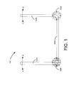
- FIG. 1 is a side view diagram of an example of a component 100 having areas that are traditionally prone to failure when manufactured using conventional methods.
- the component 100 includes a first side 102A, a second side 102B, and a third side 102C.
- the component 100 may have placed thereon forces in the direction from A to B or from B to A on the first side 102A and from C to D or from D to C on the second side 102B. These forces may cause a torque to be felt at area 104A or area 104B.
- the area 104A or 104B may experience a fail condition.
- a fail condition is a condition whereby a part of the component 100 is structurally weakened to a degree that makes the component 100 unsuitable for use.
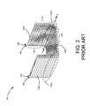
- FIG. 2 is a side-perspective view diagram of the component 100 manufactured using conventional unidirectional layering according to at least one embodiment disclosed herein.
- Conventional unidirectional layering using FFF techniques includes successive deposition of extrusions 202, with each extrusion 202 expelled from a nozzle (shown in FIG. 3 ) abutting an adjacent extrusion 202 along a seam.
- nozzle shown in FIG. 3
- FIG. 2 is a side-perspective view diagram of the component 100 manufactured using conventional unidirectional layering according to at least one embodiment disclosed herein.
- Conventional unidirectional layering using FFF techniques includes successive deposition of extrusions 202, with each extrusion 202 expelled from a nozzle (shown in FIG. 3 ) abutting an adjacent extrusion 202 along a seam.
- the presently disclosed subject matter is not limited to extruded material, as other manufacturing methods of deposition material may be used and are considered to be within the scope of the presently disclosed subject matter.
- the component 100 is manufactured through the successive deposition of layers of adjacent, parallel extrusions 202 until the component 100 is complete.
- the component 100 of FIG. 2 is made up of two layers (106 and 108) of extrusions 202 to create the first side 102A, the second side 102B, and the third side 102C, each side having a thickness equivalent to two layers 106,108 of extrusions 202.
- the extrusions 202 making up layer 106 are shown with no fill, while the extrusions 202 making up layer 108 are shown with a pattern.
- each layer 106, 108 having extrusions 202 that are all parallel to one another.
- the seams between adjacent extrusions 202 are also parallel to one another, which position the seams within areas 104A and 104B normal to the torque created if a force is applied to the first side 102A and second side 102B, respectively.
- the seams between adjacent extrusions 202 contain the least amount of material within a thickness of a layer, the seams may be the weakest areas in the component 100, particularly when subjected to torsional forces that may rotate adjacent extrusions 202 around the seams.
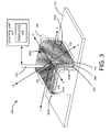
- FIG. 3 is a side-perspective view diagram of a component 300 manufactured using multi-directional layering strengthening according to at least one embodiment disclosed herein.
- the component 300 may be a component used in an aircraft. It should be noted, however, that the presently disclosed subject matter is not limited to any particular application.
- the component 300 is illustrated in an incomplete manufacturing condition, i.e. not all layers have been laid down.
- the component 300 is formed using a mandrel 312.
- the mandrel 312 has a size and shape that facilitates the formation of a desired shape for the component 300.
- the mandrel 312 may act as a build support or template for creating one or more copies of the component 300.
- the use of the mandrel 312 may facilitate the formation of a component similar to the shape illustrated in FIG. 1 . It should be noted that the presently disclosed subject matter is not limited to any particular shape of the mandrel 312, as other forms may be used to manufacture other shapes and sizes of components. Similarly, the component 300 may be formed from various materials suitable for FFF technologies. The presently disclosed subject matter is not limited to any particular type or category of materials.
- the component 300 includes a transition area 304 corresponding to the location at which the side 302A transitions to side 302C. A similar area may be found between side 302C and side 302B.
- the area 304 may be an area prone to failure if subjected to a torque and manufactured using traditional FFF techniques described above with respect to FIG. 2 .
- one or more portions of the component 300 may be manufactured using multi-directional layering techniques described herein.
- the multi-directional layering concepts described herein include laying down extrusions 202 abutting one another in layers, with each layer oriented in a different angular direction with respect to one another.
- material is first deposited in extrusions 202 abutting one another to create layer 306.
- Layer 306 includes extrusions 202 having seams that are all parallel to line CD. In other words, the extrusions 202 and corresponding seams of abutting extrusions 202 are all parallel to line CD.
- Layer 308 is then laid down on top of layer 306.
- the extrusions 202 and seams of layer 308 are deposited parallel to line EF.
- the layer 306 comprises parallel abutting extrusions 202 oriented in a first direction (or having a first orientation)
- the layer 308 comprises parallel abutting extrusions 202 oriented in a second direction (or having a second orientation).
- the layers 306 and 308 may include a first planar portion 315A and a second planar portion 315B that is not coplanar with the first planar portion 315A. In these examples, there may be an angular transition (e.g.
- the area of transition which in FIG. 3 is illustrated by way of example as transition area 304, may be an area of weakness or an area in which faults may be more likely to occur.
- the velocity of the nozzle 316 may be controlled by a control unit 317.
- the control unit 317 may include gears, actuators, and other components that control the speed and direction (e.g. velocity) of the nozzle 316. Additionally or alternatively, the control unit 317 may include one or more computing devices having a storage device that stores one or more templates 318 for, among other possibilities, controlling the velocity of the nozzle 316 as well as the amount of material being discharged from the nozzle 316.
- the one or templates 318 may include computer-readable instructions that control the nozzle 316 to create extrusions 202 oriented in a desired direction within a single layer, as well as to create multiple layers of extrusions 202 with each layer oriented in a desired angular direction according to the desired offset angles between adjacent layers.
- offset angle ⁇ is approximately 90 degrees.
- Layer 310 is then laid down on top of layer 306, but at an offset angle ⁇ with respect to layer 308.
- Offset angle ⁇ in this example may be approximately 45 degrees. It should be appreciated that the precise offset angles are not limited to 90 degrees and 45 degrees. Rather, the offset angles used between successive layers will depend on the specific implementation and the forces applied to the areas of interest (e.g., area 304) in the particular component 100 being manufactured using multi-directional layering techniques. Any number of layers may be successively applied on top of one another at any number of offset angles with respect to a preceding layer.
- the offset angle ⁇ may be equivalent to the offset angle ⁇ . In other examples, the offset angle ⁇ may be different from the offset angle ⁇ .
- the offset angle ⁇ may be determined using analytical or empirical methods. Some desirable benefits may include, but are not limited to, increased load-carrying capability, a relatively higher strength, a relatively greater stiffness, and a relatively greater durability than components manufactured using some conventional methods.
- the offset angle ⁇ may vary depending on the particular application. Some examples include angles from slightly greater than 0 degrees to 135 degrees, including combinations between layers from slightly greater than 0 degrees, to 45 degrees, 90 degrees and 135 degrees. It should be noted that the presently disclosed subject matter is not limited to any particular range of offset angle ⁇ .
- the use of multiple directions for laying down material may provide various benefits in some implementations. For example, stresses or torsional forces imparted on the area 304 may be distributed and alleviated. In another example, the multi-directional arrangement may increase the strength of the component 300 at the area 304 because, among other possible reasons, the different directions allow the transfer of forces along the different layers 306-310.
- the different directions may better absorb and disperse applied forces in a manner that is improved over unidirectional manufacturing techniques.
- the use of different directions may alleviate or reduce plying (or separation of the different layers) when a force is applied.
- the layers 306-310 may be wholly or partially manufactured in different directions, illustrated in more detail in FIG. 4 .
- FIG. 4 is a side-perspective view diagram of a layer 406 of a component manufactured using multi-directional layering strengthening.
- the layer 406 is manufactured using extrusions 202 having different directions according to at least one embodiment disclosed herein.
- the layer 406 is formed from first extrusions 420 oriented according to a first direction and second extrusions 422 oriented according to a second direction. The first extrusions 420 and the second extrusions 422 are used to form the layer 406.
- the first extrusions 420 and the second extrusions 422 are formed using a multi-directional layering process.
- the first extrusions 420 are formed in a direction along the line WX.
- the second extrusions 422 are formed in a direction along the line YZ.
- An end of the first extrusions 420 and an end of the second extrusions 422 join at junction 424.
- the multi-directional manufacturing technique used to create junction 424 may change or improve a physical characteristic of the layer 406.
- the junction 424 may provide an area in which potentially destructive forces are absorbed in a manner similar to an interstitial point defect in a crystalline lattice structure. In this manner, the propagation of a force may be abated at the junction 424, potentially decreasing the occurrence of a fail condition.
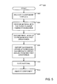
- FIG. 5 illustrates one configuration of a routine 500 for manufacturing a component using a multi-directional layering fused filament fabrication process according to at least one embodiment disclosed herein. Unless otherwise indicated, more or fewer operations may be performed than shown in the figures and described herein. Additionally, unless otherwise indicated, these operations may also be performed in a different order than those described herein.
- the routine 500 commences at operation 502 ("receive a component template"), where a component template is received.
- the component template may include computer-readable instructions that control the operation of a FFF device to create a component using the multi-directional layering techniques disclosed herein.
- the FFF device or more particularly a control unit 317 of the FFF device, executes the component template 318 to control the velocity, quantity, and orientation of material exiting the nozzle 316.
- Receiving the component template 318 may include loading the template into memory of the FFF device, or retrieving the instructions from memory.
- the routine 500 continues to operation 504 ("receive material into the fused filament fabrication device"), wherein material is received into the FFF device.
- the material may vary depending on the particular application of the presently disclosed subject matter. For example, if the mandrel is not used, the material may have integrated within the material one or more support materials.
- the support materials may be configured to allow the material to be deposited without the support provided by the mandrel.
- the material may be one or more composites, plastics, or other material suitable for component manufacture.
- the support materials may include one or more metallic, plastic, ceramic, or other substances that allow the material to be deposited without the need for a support such as the mandrel 312 of FIG. 3 .
- the presently disclosed subject matter is not limited to any particular type of material.
- the routine 500 continues to operation 506 ("deposit first layer of extrusions in a first orientation"), where a first layer of extrusions are deposited in a first orientation.
- a first orientation As described by way of example in FIG. 3 , the orientations of the various layers of the component 300 may be laid down in different orientations.
- the first layer is laid down in a first orientation, which may be followed by one or more layers in different orientations, as described immediately below.
- the routine 500 continues to operation 508 ("deposit successive layers of extrusions according to offset angles from the first orientation"), where successive layers of extrusions are deposited according to offset angles from the first orientation.
- the line EF and layer 308 are oriented at an offset angle ⁇ with respect to layer 306.
- Layer 310 is then laid down on top of layer 306, but an offset angle ⁇ with respect to layer 308.
- a single layer may be comprised of one or more offset angles.
- the first extrusions 420 are formed in a direction along the line WX and the second extrusions 422 are formed in a direction along the line YZ.
- the routine 500 continues to operation 510 ("cure material"), where the material that forms the component is allowed to cure.
- cur material the material that forms the component is allowed to cure. It should be noted that the presently disclosed subject matter is not limited to material that requires curing to complete processing, as some material may be finished without a cure cycle.
- the routine 500 continues to operation 512 ("remove component"), where the component is removed from the FFF device.
- the routine 500 may thereafter end.
- FIG. 6 illustrates a computer in which fused filament fabrication using multi-direction layering strengthening may be implemented according to at least one embodiment disclosed herein.
- the computer 600 illustrated in FIG. 6 includes one or more central processing unit(s) ("CPUs”) 602, a system memory 604, including a random-access memory (“RAM”) 606 and a read-only memory (“ROM”) 608, and a system bus 610 that couples the system memory 604 to the CPU 602.
- CPUs central processing unit
- RAM random-access memory
- ROM read-only memory
- a basic input/output system containing the routines that help to transfer information between elements within the computer 600, such as during startup, may be stored in the ROM 608.
- the computer 600 is the control unit 317 described above, or is communicatively coupled to the control unit 317.
- the CPUs 602 may be standard programmable processors that perform arithmetic and logical operations for the operation of the computer 600, such as the routine 500 described above.
- the CPUs 602 may perform the operations by transitioning from one discrete, physical state to the next through the manipulation of switching elements that differentiate between and change these states.
- Switching elements may generally include electronic circuits that maintain one of two binary states, such as flip-flops, and electronic circuits that provide an output state based on the logical combination of the states of one or more other switching elements, such as logic gates. These basic switching elements may be combined to create more complex logic circuits, including registers, adders-subtractors, arithmetic logic units, floating-point units, and the like.
- the computer 600 may also include a mass storage device 612.
- the mass storage device may be an optical disk, a magnetic storage device, or a solid state storage device.
- the mass storage device 612 may be operative to store one or more templates 318 that are configured to control the operation of the control unit 317.
- the RAM 606, ROM 608, and the mass storage device 612 may be operative to have stored thereon, either alone or in various combinations, the templates 318.
- the computer 600 may store programs and data on the mass storage device 612 by transforming the physical state of the mass storage device 612 to reflect the information being stored.
- the specific transformation of physical state may depend on various factors, in different implementations of this disclosure. Examples of such factors may include, but are not limited to, the technology used to implement the mass storage device 612, whether the mass storage device 612 is characterized as primary or secondary storage, and the like.
- the computer 600 may store information to the mass storage device 612 by issuing instructions through a storage controller to alter the magnetic characteristics of a particular location within a magnetic disk drive device, the reflective or refractive characteristics of a particular location in an optical storage device, or the electrical characteristics of a particular capacitor, transistor, or other discrete component in a solid-state storage device.
- Other transformations of physical media are possible without departing from the scope and spirit of the present description, with the foregoing examples provided only to facilitate this description.
- the computer 600 may further read information from the mass storage device 612 by detecting the physical states or characteristics of one or more particular locations within the mass storage device 612.
- the RAM 606, the ROM 608, or the mass storage device 612 may be operative as computer-readable storage mediums.
- Various aspects of the present disclosure may be stored on other types of computer-readable storage mediums, such as, but not limit to, RAM, ROM, EPROM, EEPROM, flash memory or other solid state memory technology, CD-ROM, digital versatile disks ("DVD"), HD-DVD, BLU-RAY, or other optical storage, magnetic cassettes, magnetic tape, magnetic disk storage or other magnetic storage devices, or any other medium that can be used to store the desired information and which can be accessed by the computer 600. It should be understood that when the claims are interpreted in light of this present disclosure, a computer-readable storage medium does not include energy in the form of waves or signals.
- the computer 600 also may include an input/output controller 616 for receiving and processing input from a number of other devices, including a keyboard, mouse, or electronic stylus. Similarly, the input/output controller 616 may provide an output to a display screen, a printer, or other type of output device. In some implementations, the input/output controller 616 may control the operation of one or more mechanisms that control the velocity of the nozzle 316 as well as the amount of material extruded from the nozzle 316.
- One or more embodiments may include a computer-readable storage medium manufactured so that, when read by a properly configured computing device, instructions may be provided to a fused filament fabrication system to perform operations relating to fused filament fabrication using multi-direction layering strengthening.
- a component comprising a first layer of parallel abutting extrusions oriented in a first orientation; and a second layer of parallel abutting extrusions deposited on top of the first layer and oriented in a second orientation according to a first offset angle with respect to the first orientation.
- the component is further disclosed as comprising a third layer of parallel abutting extrusions deposited on top of the second layer and oriented in a third orientation according to a second offset angle with respect to the second orientation.
- the component is disclosed herein wherein the second offset angle is equivalent to the first offset angle.
- the component is disclosed herein wherein the second offset angle is different from the first offset angle.
- the component is disclosed herein wherein the first layer comprises one or more second parallel abutting extensions oriented in an orientation different than the first orientation.
- the component is disclosed herein wherein the first layer of parallel abutting extrusions or the second layer of parallel abutting extrusions comprise a support material.
- first layer and the second layer comprise a first planar portion and a second planar portion that is not coplanar with the first planar portion.
- a method for constructing a component comprising receiving a component template comprising instructions to control the operation of a fused filament fabrication (FFF) device; depositing a first layer of parallel abutting extrusions of material in a first orientation according to the component template; and depositing a second layer of parallel abutting extrusions of the material in a second orientation according to a first offset angle with respect to the first orientation as provided by the component template.
- FFF fused filament fabrication
- the method is further disclosed as comprising curing the material.
- the method is further disclosed as comprising integrating a support material into the material.
- the method is further disclosed as comprising depositing a third layer of parallel abutting extrusions of the material in a third orientation according to a second offset angle with respect to the second orientation.
- the method is disclosed wherein the second offset angle is equivalent to the first offset angle.
- the method is disclosed wherein the second offset angle is different from the first offset angle.
- the method is disclosed wherein depositing a first layer of parallel abutting extrusions of the material in a first orientation or depositing a second layer of extrusions of the material in a second orientation is performed using a mandrel.
- first layer and the second layer comprise a first planar portion and a second planar portion that is not coplanar with the first planar portion.
- a computer-readable storage medium having instructions stored thereon which, when executed by a processor of a fused filament fabrication system, cause the fused filament fabrication system to deposit a first layer of parallel abutting extrusions of material in a first orientation according to the component template; and deposit a second layer of parallel abutting extrusions of the material in a second orientation according to a first offset angle with respect to the first orientation as provided by a component template.
- the computer-readable storage medium is further disclosed as comprising instructions to deposit a third layer of parallel abutting extrusions of the material in a third orientation according to a second offset angle with respect to the second orientation.
- the computer-readable storage medium is disclosed wherein the second offset angle is equivalent to the first offset angle.
- the computer-readable storage medium is disclosed wherein the second offset angle is different from the first offset angle.
- the computer-readable storage medium is disclosed wherein the first layer further comprises one or more second parallel abutting extrusions oriented in a different direction than the first orientation.
Landscapes
- Engineering & Computer Science (AREA)
- Chemical & Material Sciences (AREA)
- Materials Engineering (AREA)
- Mechanical Engineering (AREA)
- Physics & Mathematics (AREA)
- Manufacturing & Machinery (AREA)
- Optics & Photonics (AREA)
- Textile Engineering (AREA)
- Extrusion Moulding Of Plastics Or The Like (AREA)
Abstract
Description
- Parts and other components of aircraft may be manufactured using various manufacturing techniques depending on the performance requirements of the parts and the availability of manufacturing equipment. A technique that may be used to manufacture components is fused filament fabrication (FFF). FFF is a type of additive manufacture technique whereby material is laid down in layers. A certain number of layers are laid down in a particular arrangement to eventually form a component. FFF commonly uses thermoplastics, polycarbonate, and other similarly configured materials to form the component. FFF can be used to manufacture parts for rapid prototyping as well as rapid manufacturing. Other additive manufacturing technologies may be used in a similar manner.
- It is with respect to these and other considerations that the disclosure herein is presented.
- It should be appreciated that this Summary is provided to introduce a selection of concepts in a simplified form that are further described below in the Detailed Description. This Summary is not intended to be used to limit the scope of the claimed subject matter.
- According to one embodiment disclosed herein, a component is described. In some examples, the component may include a first layer of parallel abutting extrusions oriented in a first orientation, and a second layer of parallel abutting extrusions deposited on top of the first layer and oriented in a second orientation according to a first offset angle with respect to the first orientation.
- According to another embodiment disclosed herein, a method is described herein. In some examples, the method may include receiving a component template comprising instructions to control the operation of a fused filament fabrication (FFF) device, and depositing a first layer of parallel abutting extrusions of material in a first orientation according to the component template. The method may further include depositing a second layer of parallel abutting extrusions of the material in a second orientation according to a first offset angle with respect to the first orientation as provided by the component template.
- According to yet another embodiment disclosed herein, a computer-readable storage medium is described. In some examples, the computer-readable storage medium may have instructions stored thereon which, when executed by a processor of a fused filament fabrication system, cause the fused filament fabrication system to deposit a first layer of parallel abutting extrusions of material in a first orientation according to the component template, and deposit a second layer of parallel abutting extrusions of the material in a second orientation according to a first offset angle with respect to the first orientation as provided by a component template.
- The features, functions, and advantages that have been discussed can be achieved independently in various embodiments of the present disclosure or may be combined in yet other embodiments, further details of which can be seen with reference to the following description and drawings.
- The embodiments presented herein will become more fully understood from the detailed description and the accompanying drawings, wherein:
-
FIG. 1 is a side view diagram of an example of a component having areas possibly prone to failure. -
FIG. 2 is a side-perspective view diagram of the component manufactured using prior art FFF techniques according to at least one embodiment disclosed herein. -
FIG. 3 is a side-perspective view diagram of a component manufactured using multi-directional layering strengthening according to at least one embodiment disclosed herein. -
FIG. 4 is a side-perspective view diagram of a partial component manufactured using multi-directional layering strengthening in which a portion of the partial component is laid down in different directions according to at least one embodiment disclosed herein. -
FIG. 5 illustrates one configuration of a routine for manufacturing a component using a multi-directional layering fused filament fabrication process according to at least one embodiment disclosed herein. -
FIG. 6 illustrates a computer in which a multi-directional layering fused filament fabrication process may be implemented according to at least one embodiment disclosed herein. - The plurality of figures presented in this application illustrates variations and different aspects of the embodiments of the present disclosure. Accordingly, the detailed description on each illustration will describe the differences identified in the corresponding illustration.
- The following detailed description is directed to technologies for fused filament fabrication using multi-directional layering strengthening. In some implementations, various portions of a component may be strengthened using multi-directional layering strengthening. In some examples, a portion of a component needing increased strength is determined. An amount of strengthening desired is calculated. One or more directions of deposition of several layers are determined to achieve the amount of strengthening calculated. Thereafter, the deposition material is deposited in the one or more directions of the several layers.
- References are made to the accompanying drawings that form a part hereof, and which are shown by way of illustration, specific embodiments, or examples. Like numerals represent like elements through the several figures.
- Turning now to the figures,
FIG. 1 is a side view diagram of an example of acomponent 100 having areas that are traditionally prone to failure when manufactured using conventional methods. Thecomponent 100 includes afirst side 102A, asecond side 102B, and athird side 102C. During operation, thecomponent 100 may have placed thereon forces in the direction from A to B or from B to A on thefirst side 102A and from C to D or from D to C on thesecond side 102B. These forces may cause a torque to be felt atarea 104A orarea 104B. Depending on the amount of torque applied toarea area component 100 is structurally weakened to a degree that makes thecomponent 100 unsuitable for use. -
FIG. 2 is a side-perspective view diagram of thecomponent 100 manufactured using conventional unidirectional layering according to at least one embodiment disclosed herein. Conventional unidirectional layering using FFF techniques includes successive deposition ofextrusions 202, with eachextrusion 202 expelled from a nozzle (shown inFIG. 3 ) abutting anadjacent extrusion 202 along a seam. It should be noted that the presently disclosed subject matter is not limited to extruded material, as other manufacturing methods of deposition material may be used and are considered to be within the scope of the presently disclosed subject matter. - One seam of the
extrusions 202 is depicted inFIG. 2 as line AB for illustrative purposes. Thecomponent 100 is manufactured through the successive deposition of layers of adjacent,parallel extrusions 202 until thecomponent 100 is complete. For example, thecomponent 100 ofFIG. 2 is made up of two layers (106 and 108) ofextrusions 202 to create thefirst side 102A, thesecond side 102B, and thethird side 102C, each side having a thickness equivalent to two layers 106,108 ofextrusions 202. For clarity purposes, theextrusions 202 making uplayer 106 are shown with no fill, while theextrusions 202 making uplayer 108 are shown with a pattern. - It should be noted, that the conventional FFF techniques used to create the
component 100 result in eachlayer extrusions 202 that are all parallel to one another. In doing so, the seams betweenadjacent extrusions 202 are also parallel to one another, which position the seams withinareas first side 102A andsecond side 102B, respectively. Because the seams betweenadjacent extrusions 202 contain the least amount of material within a thickness of a layer, the seams may be the weakest areas in thecomponent 100, particularly when subjected to torsional forces that may rotateadjacent extrusions 202 around the seams. -
FIG. 3 is a side-perspective view diagram of acomponent 300 manufactured using multi-directional layering strengthening according to at least one embodiment disclosed herein. In some examples, thecomponent 300 may be a component used in an aircraft. It should be noted, however, that the presently disclosed subject matter is not limited to any particular application. - In
FIG. 3 , thecomponent 300 is illustrated in an incomplete manufacturing condition, i.e. not all layers have been laid down. Thecomponent 300 is formed using amandrel 312. Themandrel 312 has a size and shape that facilitates the formation of a desired shape for thecomponent 300. Themandrel 312 may act as a build support or template for creating one or more copies of thecomponent 300. - In some implementations, the use of the
mandrel 312 may facilitate the formation of a component similar to the shape illustrated inFIG. 1 . It should be noted that the presently disclosed subject matter is not limited to any particular shape of themandrel 312, as other forms may be used to manufacture other shapes and sizes of components. Similarly, thecomponent 300 may be formed from various materials suitable for FFF technologies. The presently disclosed subject matter is not limited to any particular type or category of materials. - The
component 300 includes atransition area 304 corresponding to the location at which theside 302A transitions to side 302C. A similar area may be found betweenside 302C andside 302B. In some implementations, thearea 304 may be an area prone to failure if subjected to a torque and manufactured using traditional FFF techniques described above with respect toFIG. 2 . However, to reduce the probability thatarea 304 may experience a fail condition under certain loads or forces, one or more portions of thecomponent 300 may be manufactured using multi-directional layering techniques described herein. - In the example illustrated in
FIG. 3 , the multi-directional layering concepts described herein include laying downextrusions 202 abutting one another in layers, with each layer oriented in a different angular direction with respect to one another. For example, usingnozzle 316, material is first deposited inextrusions 202 abutting one another to createlayer 306.Layer 306 includesextrusions 202 having seams that are all parallel to line CD. In other words, theextrusions 202 and corresponding seams of abuttingextrusions 202 are all parallel to line CD.Layer 308 is then laid down on top oflayer 306. - However, instead of laying down
layer 308 withextrusions 202 and seams parallel to line CD, as would be done with conventional FFF techniques, theextrusions 202 and seams oflayer 308 are deposited parallel to line EF. In some examples, therefore, thelayer 306 comprises parallel abuttingextrusions 202 oriented in a first direction (or having a first orientation), while thelayer 308 comprises parallel abuttingextrusions 202 oriented in a second direction (or having a second orientation). Thelayers planar portion 315A and a secondplanar portion 315B that is not coplanar with the firstplanar portion 315A. In these examples, there may be an angular transition (e.g. a curve or bend) between the firstplanar portion 315A and the secondplanar portion 315B. In some examples, the area of transition, which inFIG. 3 is illustrated by way of example astransition area 304, may be an area of weakness or an area in which faults may be more likely to occur. - In some examples, the velocity of the
nozzle 316 may be controlled by acontrol unit 317. Thecontrol unit 317 may include gears, actuators, and other components that control the speed and direction (e.g. velocity) of thenozzle 316. Additionally or alternatively, thecontrol unit 317 may include one or more computing devices having a storage device that stores one ormore templates 318 for, among other possibilities, controlling the velocity of thenozzle 316 as well as the amount of material being discharged from thenozzle 316. The one ortemplates 318 may include computer-readable instructions that control thenozzle 316 to createextrusions 202 oriented in a desired direction within a single layer, as well as to create multiple layers ofextrusions 202 with each layer oriented in a desired angular direction according to the desired offset angles between adjacent layers. - For example, according to this multi-directional layering technique, line EF and
layer 308 are oriented at an offset angle α with respect tolayer 306. In this example, offset angle α is approximately 90 degrees.Layer 310 is then laid down on top oflayer 306, but at an offset angle β with respect tolayer 308. Offset angle β in this example may be approximately 45 degrees. It should be appreciated that the precise offset angles are not limited to 90 degrees and 45 degrees. Rather, the offset angles used between successive layers will depend on the specific implementation and the forces applied to the areas of interest (e.g., area 304) in theparticular component 100 being manufactured using multi-directional layering techniques. Any number of layers may be successively applied on top of one another at any number of offset angles with respect to a preceding layer. In some examples, the offset angle α may be equivalent to the offset angle β. In other examples, the offset angle α may be different from the offset angle β. - In some implementations, the offset angle β may be determined using analytical or empirical methods. Some desirable benefits may include, but are not limited to, increased load-carrying capability, a relatively higher strength, a relatively greater stiffness, and a relatively greater durability than components manufactured using some conventional methods. The offset angle β may vary depending on the particular application. Some examples include angles from slightly greater than 0 degrees to 135 degrees, including combinations between layers from slightly greater than 0 degrees, to 45 degrees, 90 degrees and 135 degrees. It should be noted that the presently disclosed subject matter is not limited to any particular range of offset angle β.
- The use of multiple directions for laying down material may provide various benefits in some implementations. For example, stresses or torsional forces imparted on the
area 304 may be distributed and alleviated. In another example, the multi-directional arrangement may increase the strength of thecomponent 300 at thearea 304 because, among other possible reasons, the different directions allow the transfer of forces along the different layers 306-310. - Further, the different directions may better absorb and disperse applied forces in a manner that is improved over unidirectional manufacturing techniques. In still further applications, the use of different directions may alleviate or reduce plying (or separation of the different layers) when a force is applied. In some configurations, the layers 306-310 may be wholly or partially manufactured in different directions, illustrated in more detail in
FIG. 4 . -
FIG. 4 is a side-perspective view diagram of alayer 406 of a component manufactured using multi-directional layering strengthening. Thelayer 406 is manufactured usingextrusions 202 having different directions according to at least one embodiment disclosed herein. InFIG. 4 , thelayer 406 is formed fromfirst extrusions 420 oriented according to a first direction andsecond extrusions 422 oriented according to a second direction. Thefirst extrusions 420 and thesecond extrusions 422 are used to form thelayer 406. - The
first extrusions 420 and thesecond extrusions 422 are formed using a multi-directional layering process. Thefirst extrusions 420 are formed in a direction along the line WX. Thesecond extrusions 422 are formed in a direction along the line YZ. An end of thefirst extrusions 420 and an end of thesecond extrusions 422 join atjunction 424. In some implementations, the multi-directional manufacturing technique used to createjunction 424 may change or improve a physical characteristic of thelayer 406. For example, thejunction 424 may provide an area in which potentially destructive forces are absorbed in a manner similar to an interstitial point defect in a crystalline lattice structure. In this manner, the propagation of a force may be abated at thejunction 424, potentially decreasing the occurrence of a fail condition. -
FIG. 5 illustrates one configuration of a routine 500 for manufacturing a component using a multi-directional layering fused filament fabrication process according to at least one embodiment disclosed herein. Unless otherwise indicated, more or fewer operations may be performed than shown in the figures and described herein. Additionally, unless otherwise indicated, these operations may also be performed in a different order than those described herein. - The routine 500 commences at operation 502 ("receive a component template"), where a component template is received. In some examples, the component template may include computer-readable instructions that control the operation of a FFF device to create a component using the multi-directional layering techniques disclosed herein. As described above, the FFF device, or more particularly a
control unit 317 of the FFF device, executes thecomponent template 318 to control the velocity, quantity, and orientation of material exiting thenozzle 316. Receiving thecomponent template 318 may include loading the template into memory of the FFF device, or retrieving the instructions from memory. - The routine 500 continues to operation 504 ("receive material into the fused filament fabrication device"), wherein material is received into the FFF device. The material may vary depending on the particular application of the presently disclosed subject matter. For example, if the mandrel is not used, the material may have integrated within the material one or more support materials. The support materials may be configured to allow the material to be deposited without the support provided by the mandrel. The material may be one or more composites, plastics, or other material suitable for component manufacture. The support materials may include one or more metallic, plastic, ceramic, or other substances that allow the material to be deposited without the need for a support such as the
mandrel 312 ofFIG. 3 . The presently disclosed subject matter is not limited to any particular type of material. - The routine 500 continues to operation 506 ("deposit first layer of extrusions in a first orientation"), where a first layer of extrusions are deposited in a first orientation. As described by way of example in
FIG. 3 , the orientations of the various layers of thecomponent 300 may be laid down in different orientations. Inoperation 506, the first layer is laid down in a first orientation, which may be followed by one or more layers in different orientations, as described immediately below. - The routine 500 continues to operation 508 ("deposit successive layers of extrusions according to offset angles from the first orientation"), where successive layers of extrusions are deposited according to offset angles from the first orientation. As described by way of example in
FIG. 3 , above, the line EF andlayer 308 are oriented at an offset angle α with respect tolayer 306.Layer 310 is then laid down on top oflayer 306, but an offset angle β with respect tolayer 308. As described by way of further example inFIG. 4 , a single layer may be comprised of one or more offset angles. As described above, thefirst extrusions 420 are formed in a direction along the line WX and thesecond extrusions 422 are formed in a direction along the line YZ. - The routine 500 continues to operation 510 ("cure material"), where the material that forms the component is allowed to cure. It should be noted that the presently disclosed subject matter is not limited to material that requires curing to complete processing, as some material may be finished without a cure cycle.
- The routine 500 continues to operation 512 ("remove component"), where the component is removed from the FFF device. The routine 500 may thereafter end.
-
FIG. 6 illustrates a computer in which fused filament fabrication using multi-direction layering strengthening may be implemented according to at least one embodiment disclosed herein. Thecomputer 600 illustrated inFIG. 6 includes one or more central processing unit(s) ("CPUs") 602, asystem memory 604, including a random-access memory ("RAM") 606 and a read-only memory ("ROM") 608, and asystem bus 610 that couples thesystem memory 604 to theCPU 602. A basic input/output system containing the routines that help to transfer information between elements within thecomputer 600, such as during startup, may be stored in theROM 608. According to various embodiments, thecomputer 600 is thecontrol unit 317 described above, or is communicatively coupled to thecontrol unit 317. - The
CPUs 602 may be standard programmable processors that perform arithmetic and logical operations for the operation of thecomputer 600, such as the routine 500 described above. TheCPUs 602 may perform the operations by transitioning from one discrete, physical state to the next through the manipulation of switching elements that differentiate between and change these states. Switching elements may generally include electronic circuits that maintain one of two binary states, such as flip-flops, and electronic circuits that provide an output state based on the logical combination of the states of one or more other switching elements, such as logic gates. These basic switching elements may be combined to create more complex logic circuits, including registers, adders-subtractors, arithmetic logic units, floating-point units, and the like. - The
computer 600 may also include amass storage device 612. The mass storage device may be an optical disk, a magnetic storage device, or a solid state storage device. Themass storage device 612 may be operative to store one ormore templates 318 that are configured to control the operation of thecontrol unit 317. In another configuration, the RAM 606,ROM 608, and themass storage device 612 may be operative to have stored thereon, either alone or in various combinations, thetemplates 318. - The
computer 600 may store programs and data on themass storage device 612 by transforming the physical state of themass storage device 612 to reflect the information being stored. The specific transformation of physical state may depend on various factors, in different implementations of this disclosure. Examples of such factors may include, but are not limited to, the technology used to implement themass storage device 612, whether themass storage device 612 is characterized as primary or secondary storage, and the like. - For example, the
computer 600 may store information to themass storage device 612 by issuing instructions through a storage controller to alter the magnetic characteristics of a particular location within a magnetic disk drive device, the reflective or refractive characteristics of a particular location in an optical storage device, or the electrical characteristics of a particular capacitor, transistor, or other discrete component in a solid-state storage device. Other transformations of physical media are possible without departing from the scope and spirit of the present description, with the foregoing examples provided only to facilitate this description. Thecomputer 600 may further read information from themass storage device 612 by detecting the physical states or characteristics of one or more particular locations within themass storage device 612. - The RAM 606, the
ROM 608, or themass storage device 612 may be operative as computer-readable storage mediums. Various aspects of the present disclosure may be stored on other types of computer-readable storage mediums, such as, but not limit to, RAM, ROM, EPROM, EEPROM, flash memory or other solid state memory technology, CD-ROM, digital versatile disks ("DVD"), HD-DVD, BLU-RAY, or other optical storage, magnetic cassettes, magnetic tape, magnetic disk storage or other magnetic storage devices, or any other medium that can be used to store the desired information and which can be accessed by thecomputer 600. It should be understood that when the claims are interpreted in light of this present disclosure, a computer-readable storage medium does not include energy in the form of waves or signals. - The
computer 600 also may include an input/output controller 616 for receiving and processing input from a number of other devices, including a keyboard, mouse, or electronic stylus. Similarly, the input/output controller 616 may provide an output to a display screen, a printer, or other type of output device. In some implementations, the input/output controller 616 may control the operation of one or more mechanisms that control the velocity of thenozzle 316 as well as the amount of material extruded from thenozzle 316. One or more embodiments may include a computer-readable storage medium manufactured so that, when read by a properly configured computing device, instructions may be provided to a fused filament fabrication system to perform operations relating to fused filament fabrication using multi-direction layering strengthening. - According to an aspect of the present disclosure there is provided a component comprising a first layer of parallel abutting extrusions oriented in a first orientation; and a second layer of parallel abutting extrusions deposited on top of the first layer and oriented in a second orientation according to a first offset angle with respect to the first orientation.
- The component is further disclosed as comprising a third layer of parallel abutting extrusions deposited on top of the second layer and oriented in a third orientation according to a second offset angle with respect to the second orientation.
- The component is disclosed herein wherein the second offset angle is equivalent to the first offset angle.
- The component is disclosed herein wherein the second offset angle is different from the first offset angle.
- The component is disclosed herein wherein the first layer comprises one or more second parallel abutting extensions oriented in an orientation different than the first orientation.
- The component is disclosed herein wherein the first layer of parallel abutting extrusions or the second layer of parallel abutting extrusions comprise a support material.
- The component is disclosed herein wherein the first layer and the second layer comprise a first planar portion and a second planar portion that is not coplanar with the first planar portion.
- According to another aspect of the present disclosure there is provided a method for constructing a component, comprising receiving a component template comprising instructions to control the operation of a fused filament fabrication (FFF) device; depositing a first layer of parallel abutting extrusions of material in a first orientation according to the component template; and depositing a second layer of parallel abutting extrusions of the material in a second orientation according to a first offset angle with respect to the first orientation as provided by the component template.
- The method is further disclosed as comprising curing the material.
- The method is further disclosed as comprising integrating a support material into the material.
- The method is further disclosed as comprising depositing a third layer of parallel abutting extrusions of the material in a third orientation according to a second offset angle with respect to the second orientation.
- The method is disclosed wherein the second offset angle is equivalent to the first offset angle.
- The method is disclosed wherein the second offset angle is different from the first offset angle.
- The method is disclosed wherein depositing a first layer of parallel abutting extrusions of the material in a first orientation or depositing a second layer of extrusions of the material in a second orientation is performed using a mandrel.
- The method is disclosed wherein the first layer and the second layer comprise a first planar portion and a second planar portion that is not coplanar with the first planar portion.
- According to another aspect of the present disclosure there is provided a computer-readable storage medium having instructions stored thereon which, when executed by a processor of a fused filament fabrication system, cause the fused filament fabrication system to deposit a first layer of parallel abutting extrusions of material in a first orientation according to the component template; and deposit a second layer of parallel abutting extrusions of the material in a second orientation according to a first offset angle with respect to the first orientation as provided by a component template.
- The computer-readable storage medium is further disclosed as comprising instructions to deposit a third layer of parallel abutting extrusions of the material in a third orientation according to a second offset angle with respect to the second orientation.
- The computer-readable storage medium is disclosed wherein the second offset angle is equivalent to the first offset angle.
- The computer-readable storage medium is disclosed wherein the second offset angle is different from the first offset angle.
- The computer-readable storage medium is disclosed wherein the first layer further comprises one or more second parallel abutting extrusions oriented in a different direction than the first orientation.
- The subject matter described above is provided by way of illustration only and should not be construed as limiting. Various modifications and changes may be made to the subject matter described herein without following the example embodiments and applications illustrated and described, and without departing from the true spirit and scope of the present disclosure, which is set forth in the following claims.
Claims (15)
- A component (100; 300) comprising:a first layer (106) of parallel abutting extrusions (202) oriented in a first orientation; anda second layer (108) of parallel abutting extrusions (202) deposited on top of the first layer (106) and oriented in a second orientation according to a first offset angle with respect to the first orientation.
- The component of claim 1, further comprising a third layer of parallel abutting extrusions (202) deposited on top of the second layer (108) and oriented in a third orientation according to a second offset angle with respect to the second orientation.
- The component of claim 2, wherein the second offset angle is equivalent to the first offset angle.
- The component of claim 2, wherein the second offset angle is different from the first offset angle.
- The component of one of claims 1 to 4, wherein the first layer (106) comprises one or more second parallel abutting extensions (202) oriented in an orientation different than the first orientation.
- The component of one of claims 1 to 5, wherein the first layer (106) of parallel abutting extrusions (202) or the second layer (108) of parallel abutting extrusions (202) comprise a support material.
- The component of one of claims 1 to 6, wherein the first layer (106) and the second layer (108) comprise a first planar portion (315) and a second planar portion (315) that is not coplanar with the first planar portion (315).
- A method for constructing a component (100), comprising:receiving a component template (318) comprising instructions to control the operation of a fused filament fabrication (FFF) device;depositing a first layer (106) of parallel abutting extrusions (202) of material in a first orientation according to the component template (318); anddepositing a second layer (108) of parallel abutting extrusions (202) of the material in a second orientation according to a first offset angle with respect to the first orientation as provided by the component template (318).
- The method of claim 8, further comprising curing the material.
- The method of claim 8 or 9, further comprising integrating a support material into the material.
- The method of one of claims 8 to 10, further comprising depositing a third layer of parallel abutting extrusions (202) of the material in a third orientation according to a second offset angle with respect to the second orientation.
- The method of claim 11, wherein the second offset angle is equivalent to the first offset angle.
- The method of claim 11, wherein the second offset angle is different from the first offset angle.
- The method of one of claims 8 to 13, wherein depositing a first layer (106) of parallel abutting extrusions (202) of the material in a first orientation or depositing a second layer (108) of extrusions (202) of the material in a second orientation is performed using a mandrel (312).
- The method of one of claims 8 to 14, wherein the first layer (106) and the second layer (108) comprise a first planar portion (315) and a second planar portion (315) that is not coplanar with the first planar portion (315).
Applications Claiming Priority (1)
| Application Number | Priority Date | Filing Date | Title |
|---|---|---|---|
| US14/487,422 US9895836B2 (en) | 2014-09-16 | 2014-09-16 | Fused filament fabricated part using multi-directional layering |
Publications (2)
| Publication Number | Publication Date |
|---|---|
| EP2998110A1 true EP2998110A1 (en) | 2016-03-23 |
| EP2998110B1 EP2998110B1 (en) | 2023-12-20 |
Family
ID=53783045
Family Applications (1)
| Application Number | Title | Priority Date | Filing Date |
|---|---|---|---|
| EP15174018.0A Active EP2998110B1 (en) | 2014-09-16 | 2015-06-26 | Fused filament fabrication method using multi-directional strengthening layering |
Country Status (3)
| Country | Link |
|---|---|
| US (1) | US9895836B2 (en) |
| EP (1) | EP2998110B1 (en) |
| CA (1) | CA2896045C (en) |
Cited By (1)
| Publication number | Priority date | Publication date | Assignee | Title |
|---|---|---|---|---|
| CN111867808A (en) * | 2018-01-18 | 2020-10-30 | 北极生物材料有限公司 | Fiber Reinforced 3D Printing |
Families Citing this family (7)
| Publication number | Priority date | Publication date | Assignee | Title |
|---|---|---|---|---|
| WO2016177894A1 (en) * | 2015-05-07 | 2016-11-10 | Addifab Aps | Additive manufacturing yield improvement |
| CN105427997B (en) * | 2015-12-31 | 2017-10-03 | 黄曦雨 | A kind of reactor electromagnetic coil skeleton and in-seam support body and shell body thereon |
| US10668534B2 (en) | 2017-03-06 | 2020-06-02 | General Electric Company | Leg elimination strategy for hatch pattern |
| US10828700B2 (en) | 2017-03-06 | 2020-11-10 | General Electric Company | Triangle hatch pattern for additive manufacturing |
| JP6961972B2 (en) * | 2017-03-24 | 2021-11-05 | 富士フイルムビジネスイノベーション株式会社 | Three-dimensional shape molding equipment, information processing equipment and programs |
| US10046511B1 (en) | 2017-12-26 | 2018-08-14 | Arevo, Inc. | Alleviating torsional forces on fiber-reinforced thermoplastic filament |
| US11292190B2 (en) | 2017-12-26 | 2022-04-05 | Arevo, Inc. | Depositing arced portions of fiber-reinforced thermoplastic filament |
Citations (4)
| Publication number | Priority date | Publication date | Assignee | Title |
|---|---|---|---|---|
| US6114050A (en) * | 1996-01-11 | 2000-09-05 | The Boeing Company | Titanium-polymer hybrid laminates |
| US20060266741A1 (en) * | 2005-05-27 | 2006-11-30 | Snecma | Process for manufacturing a bonded sheet composed of ceramic filaments with a metal matrix, device for implementing said process, bonded sheet obtained by said process |
| US20130122763A1 (en) * | 2009-10-06 | 2013-05-16 | Composite Tech, LLC. | Composite materials |
| EP2671707A1 (en) * | 2012-06-08 | 2013-12-11 | The Boeing Company | Optimized cross-ply orientation in composite laminates |
Family Cites Families (6)
| Publication number | Priority date | Publication date | Assignee | Title |
|---|---|---|---|---|
| US20070036964A1 (en) * | 2005-08-15 | 2007-02-15 | Lockheed Martin Corporation | Direct manufacturing using thermoplastic and thermoset |
| DE102007014683A1 (en) * | 2007-03-27 | 2008-10-09 | Eos Gmbh Electro Optical Systems | Method and device for producing a three-dimensional object |
| EP2459361B1 (en) | 2009-07-29 | 2019-11-06 | Zydex Pty Ltd | 3d printing on a rotating cylindrical surface |
| US8579620B2 (en) * | 2011-03-02 | 2013-11-12 | Andy Wu | Single-action three-dimensional model printing methods |
| EP2776233B1 (en) * | 2011-08-29 | 2017-12-27 | Impossible Objects, Inc. | Methods and apparatus for 3d fabrication |
| US8944802B2 (en) * | 2013-01-25 | 2015-02-03 | Radiant Fabrication, Inc. | Fixed printhead fused filament fabrication printer and method |
-
2014
- 2014-09-16 US US14/487,422 patent/US9895836B2/en not_active Expired - Fee Related
-
2015
- 2015-06-26 EP EP15174018.0A patent/EP2998110B1/en active Active
- 2015-06-29 CA CA2896045A patent/CA2896045C/en active Active
Patent Citations (4)
| Publication number | Priority date | Publication date | Assignee | Title |
|---|---|---|---|---|
| US6114050A (en) * | 1996-01-11 | 2000-09-05 | The Boeing Company | Titanium-polymer hybrid laminates |
| US20060266741A1 (en) * | 2005-05-27 | 2006-11-30 | Snecma | Process for manufacturing a bonded sheet composed of ceramic filaments with a metal matrix, device for implementing said process, bonded sheet obtained by said process |
| US20130122763A1 (en) * | 2009-10-06 | 2013-05-16 | Composite Tech, LLC. | Composite materials |
| EP2671707A1 (en) * | 2012-06-08 | 2013-12-11 | The Boeing Company | Optimized cross-ply orientation in composite laminates |
Cited By (1)
| Publication number | Priority date | Publication date | Assignee | Title |
|---|---|---|---|---|
| CN111867808A (en) * | 2018-01-18 | 2020-10-30 | 北极生物材料有限公司 | Fiber Reinforced 3D Printing |
Also Published As
| Publication number | Publication date |
|---|---|
| CA2896045A1 (en) | 2016-03-16 |
| EP2998110B1 (en) | 2023-12-20 |
| US9895836B2 (en) | 2018-02-20 |
| US20160075086A1 (en) | 2016-03-17 |
| CA2896045C (en) | 2017-08-08 |
Similar Documents
| Publication | Publication Date | Title |
|---|---|---|
| US9895836B2 (en) | Fused filament fabricated part using multi-directional layering | |
| US11891162B2 (en) | Additively manufactured septa for acoustic panels | |
| US8165703B2 (en) | Computer assisted method for the advanced design of bent parts of composite material | |
| CN108140064B (en) | Method and system for distributing a multi-layered composite within a volume of a structure containing inclusions | |
| US10467350B2 (en) | Optimization of ply orientations for multi-layer composite parts | |
| US11453163B2 (en) | Additive manufacturing with magnetic manipulation | |
| US20180370613A1 (en) | Composite structure with integrated hinge | |
| EP3219470B1 (en) | Three dimensional printing apparatus | |
| US20180093427A1 (en) | Three dimensional printing apparatus and three dimensional printing method thereof | |
| Wu et al. | Simultaneous discrete topology optimization of ply orientation and thickness for carbon fiber reinforced plastic-laminated structures | |
| CN111386163A (en) | Apparatus and method for additively manufacturing grid structures | |
| Zhou et al. | Large-scale three-dimensional anisotropic topology optimization of variable-axial lightweight composite structures | |
| Lozano et al. | A design algorithm to model fibre paths for manufacturing of structurally optimised composite laminates | |
| Wang et al. | A new path planning strategy driven by geometric features and tensile properties for 3D printing of continuous fiber reinforced thermoplastic composites | |
| Irisarri et al. | A novel design method for the fast and cost-effective manufacture of composite parts employing the Quilted Stratum Process | |
| CN107336433A (en) | A kind of adaptive thickness layered approach of 3D printing | |
| KR102556715B1 (en) | System and method for self-supporting modification of the design of an object for additive manufacturing | |
| US11628636B2 (en) | Automated tow/tape placement system | |
| US12109764B2 (en) | Automated placement of composite material | |
| Kubalak et al. | Simultaneous topology and toolpath optimization for layer-free multi-axis additive manufacturing of 3D composite structures | |
| EP4274692A1 (en) | Optimized rib-stiffened composite structure | |
| US20230211545A1 (en) | Techniques for generating composite structures that combine metal and polymer compositions | |
| Cao et al. | Comparative study on bezier curve and linear variable angle method for variable stiffness laminates | |
| US20210129421A1 (en) | Additive manufacturing of wireframe objects | |
| Adelnia et al. | Production of wind tunnel testing models with use of rapid prototyping methods |
Legal Events
| Date | Code | Title | Description |
|---|---|---|---|
| PUAI | Public reference made under article 153(3) epc to a published international application that has entered the european phase |
Free format text: ORIGINAL CODE: 0009012 |
|
| AK | Designated contracting states |
Kind code of ref document: A1 Designated state(s): AL AT BE BG CH CY CZ DE DK EE ES FI FR GB GR HR HU IE IS IT LI LT LU LV MC MK MT NL NO PL PT RO RS SE SI SK SM TR |
|
| AX | Request for extension of the european patent |
Extension state: BA ME |
|
| 17P | Request for examination filed |
Effective date: 20160802 |
|
| RBV | Designated contracting states (corrected) |
Designated state(s): AL AT BE BG CH CY CZ DE DK EE ES FI FR GB GR HR HU IE IS IT LI LT LU LV MC MK MT NL NO PL PT RO RS SE SI SK SM TR |
|
| STAA | Information on the status of an ep patent application or granted ep patent |
Free format text: STATUS: EXAMINATION IS IN PROGRESS |
|
| 17Q | First examination report despatched |
Effective date: 20180718 |
|
| RAP3 | Party data changed (applicant data changed or rights of an application transferred) |
Owner name: THE BOEING COMPANY |
|
| GRAP | Despatch of communication of intention to grant a patent |
Free format text: ORIGINAL CODE: EPIDOSNIGR1 |
|
| STAA | Information on the status of an ep patent application or granted ep patent |
Free format text: STATUS: GRANT OF PATENT IS INTENDED |
|
| RIC1 | Information provided on ipc code assigned before grant |
Ipc: B32B 3/02 20060101ALI20230430BHEP Ipc: B32B 5/12 20060101ALI20230430BHEP Ipc: B32B 5/02 20060101AFI20230430BHEP |
|
| GRAJ | Information related to disapproval of communication of intention to grant by the applicant or resumption of examination proceedings by the epo deleted |
Free format text: ORIGINAL CODE: EPIDOSDIGR1 |
|
| STAA | Information on the status of an ep patent application or granted ep patent |
Free format text: STATUS: EXAMINATION IS IN PROGRESS |
|
| INTG | Intention to grant announced |
Effective date: 20230602 |
|
| GRAP | Despatch of communication of intention to grant a patent |
Free format text: ORIGINAL CODE: EPIDOSNIGR1 |
|
| STAA | Information on the status of an ep patent application or granted ep patent |
Free format text: STATUS: GRANT OF PATENT IS INTENDED |
|
| INTC | Intention to grant announced (deleted) | ||
| INTG | Intention to grant announced |
Effective date: 20230703 |
|
| P01 | Opt-out of the competence of the unified patent court (upc) registered |
Effective date: 20230719 |
|
| GRAS | Grant fee paid |
Free format text: ORIGINAL CODE: EPIDOSNIGR3 |
|
| GRAA | (expected) grant |
Free format text: ORIGINAL CODE: 0009210 |
|
| STAA | Information on the status of an ep patent application or granted ep patent |
Free format text: STATUS: THE PATENT HAS BEEN GRANTED |
|
| AK | Designated contracting states |
Kind code of ref document: B1 Designated state(s): AL AT BE BG CH CY CZ DE DK EE ES FI FR GB GR HR HU IE IS IT LI LT LU LV MC MK MT NL NO PL PT RO RS SE SI SK SM TR |
|
| REG | Reference to a national code |
Ref country code: GB Ref legal event code: FG4D |
|
| REG | Reference to a national code |
Ref country code: DE Ref legal event code: R096 Ref document number: 602015086983 Country of ref document: DE |
|
| REG | Reference to a national code |
Ref country code: CH Ref legal event code: EP |
|
| REG | Reference to a national code |
Ref country code: IE Ref legal event code: FG4D |
|
| PG25 | Lapsed in a contracting state [announced via postgrant information from national office to epo] |
Ref country code: GR Free format text: LAPSE BECAUSE OF FAILURE TO SUBMIT A TRANSLATION OF THE DESCRIPTION OR TO PAY THE FEE WITHIN THE PRESCRIBED TIME-LIMIT Effective date: 20240321 |
|
| REG | Reference to a national code |
Ref country code: LT Ref legal event code: MG9D |
|
| PG25 | Lapsed in a contracting state [announced via postgrant information from national office to epo] |
Ref country code: LT Free format text: LAPSE BECAUSE OF FAILURE TO SUBMIT A TRANSLATION OF THE DESCRIPTION OR TO PAY THE FEE WITHIN THE PRESCRIBED TIME-LIMIT Effective date: 20231220 |
|
| REG | Reference to a national code |
Ref country code: NL Ref legal event code: MP Effective date: 20231220 |
|
| PG25 | Lapsed in a contracting state [announced via postgrant information from national office to epo] |
Ref country code: ES Free format text: LAPSE BECAUSE OF FAILURE TO SUBMIT A TRANSLATION OF THE DESCRIPTION OR TO PAY THE FEE WITHIN THE PRESCRIBED TIME-LIMIT Effective date: 20231220 |
|
| PG25 | Lapsed in a contracting state [announced via postgrant information from national office to epo] |
Ref country code: LT Free format text: LAPSE BECAUSE OF FAILURE TO SUBMIT A TRANSLATION OF THE DESCRIPTION OR TO PAY THE FEE WITHIN THE PRESCRIBED TIME-LIMIT Effective date: 20231220 Ref country code: GR Free format text: LAPSE BECAUSE OF FAILURE TO SUBMIT A TRANSLATION OF THE DESCRIPTION OR TO PAY THE FEE WITHIN THE PRESCRIBED TIME-LIMIT Effective date: 20240321 Ref country code: FI Free format text: LAPSE BECAUSE OF FAILURE TO SUBMIT A TRANSLATION OF THE DESCRIPTION OR TO PAY THE FEE WITHIN THE PRESCRIBED TIME-LIMIT Effective date: 20231220 Ref country code: ES Free format text: LAPSE BECAUSE OF FAILURE TO SUBMIT A TRANSLATION OF THE DESCRIPTION OR TO PAY THE FEE WITHIN THE PRESCRIBED TIME-LIMIT Effective date: 20231220 Ref country code: BG Free format text: LAPSE BECAUSE OF FAILURE TO SUBMIT A TRANSLATION OF THE DESCRIPTION OR TO PAY THE FEE WITHIN THE PRESCRIBED TIME-LIMIT Effective date: 20240320 |
|
| REG | Reference to a national code |
Ref country code: AT Ref legal event code: MK05 Ref document number: 1642146 Country of ref document: AT Kind code of ref document: T Effective date: 20231220 |
|
| PG25 | Lapsed in a contracting state [announced via postgrant information from national office to epo] |
Ref country code: NL Free format text: LAPSE BECAUSE OF FAILURE TO SUBMIT A TRANSLATION OF THE DESCRIPTION OR TO PAY THE FEE WITHIN THE PRESCRIBED TIME-LIMIT Effective date: 20231220 |
|
| PG25 | Lapsed in a contracting state [announced via postgrant information from national office to epo] |
Ref country code: SE Free format text: LAPSE BECAUSE OF FAILURE TO SUBMIT A TRANSLATION OF THE DESCRIPTION OR TO PAY THE FEE WITHIN THE PRESCRIBED TIME-LIMIT Effective date: 20231220 Ref country code: RS Free format text: LAPSE BECAUSE OF FAILURE TO SUBMIT A TRANSLATION OF THE DESCRIPTION OR TO PAY THE FEE WITHIN THE PRESCRIBED TIME-LIMIT Effective date: 20231220 Ref country code: NO Free format text: LAPSE BECAUSE OF FAILURE TO SUBMIT A TRANSLATION OF THE DESCRIPTION OR TO PAY THE FEE WITHIN THE PRESCRIBED TIME-LIMIT Effective date: 20240320 Ref country code: NL Free format text: LAPSE BECAUSE OF FAILURE TO SUBMIT A TRANSLATION OF THE DESCRIPTION OR TO PAY THE FEE WITHIN THE PRESCRIBED TIME-LIMIT Effective date: 20231220 Ref country code: LV Free format text: LAPSE BECAUSE OF FAILURE TO SUBMIT A TRANSLATION OF THE DESCRIPTION OR TO PAY THE FEE WITHIN THE PRESCRIBED TIME-LIMIT Effective date: 20231220 Ref country code: HR Free format text: LAPSE BECAUSE OF FAILURE TO SUBMIT A TRANSLATION OF THE DESCRIPTION OR TO PAY THE FEE WITHIN THE PRESCRIBED TIME-LIMIT Effective date: 20231220 |
|
| PG25 | Lapsed in a contracting state [announced via postgrant information from national office to epo] |
Ref country code: IS Free format text: LAPSE BECAUSE OF FAILURE TO SUBMIT A TRANSLATION OF THE DESCRIPTION OR TO PAY THE FEE WITHIN THE PRESCRIBED TIME-LIMIT Effective date: 20240420 |
|
| PGFP | Annual fee paid to national office [announced via postgrant information from national office to epo] |
Ref country code: GB Payment date: 20240627 Year of fee payment: 10 |
|
| PG25 | Lapsed in a contracting state [announced via postgrant information from national office to epo] |
Ref country code: CZ Free format text: LAPSE BECAUSE OF FAILURE TO SUBMIT A TRANSLATION OF THE DESCRIPTION OR TO PAY THE FEE WITHIN THE PRESCRIBED TIME-LIMIT Effective date: 20231220 Ref country code: AT Free format text: LAPSE BECAUSE OF FAILURE TO SUBMIT A TRANSLATION OF THE DESCRIPTION OR TO PAY THE FEE WITHIN THE PRESCRIBED TIME-LIMIT Effective date: 20231220 |
|
| PG25 | Lapsed in a contracting state [announced via postgrant information from national office to epo] |
Ref country code: SK Free format text: LAPSE BECAUSE OF FAILURE TO SUBMIT A TRANSLATION OF THE DESCRIPTION OR TO PAY THE FEE WITHIN THE PRESCRIBED TIME-LIMIT Effective date: 20231220 |
|
| PG25 | Lapsed in a contracting state [announced via postgrant information from national office to epo] |
Ref country code: SM Free format text: LAPSE BECAUSE OF FAILURE TO SUBMIT A TRANSLATION OF THE DESCRIPTION OR TO PAY THE FEE WITHIN THE PRESCRIBED TIME-LIMIT Effective date: 20231220 Ref country code: SK Free format text: LAPSE BECAUSE OF FAILURE TO SUBMIT A TRANSLATION OF THE DESCRIPTION OR TO PAY THE FEE WITHIN THE PRESCRIBED TIME-LIMIT Effective date: 20231220 Ref country code: RO Free format text: LAPSE BECAUSE OF FAILURE TO SUBMIT A TRANSLATION OF THE DESCRIPTION OR TO PAY THE FEE WITHIN THE PRESCRIBED TIME-LIMIT Effective date: 20231220 Ref country code: IT Free format text: LAPSE BECAUSE OF FAILURE TO SUBMIT A TRANSLATION OF THE DESCRIPTION OR TO PAY THE FEE WITHIN THE PRESCRIBED TIME-LIMIT Effective date: 20231220 Ref country code: IS Free format text: LAPSE BECAUSE OF FAILURE TO SUBMIT A TRANSLATION OF THE DESCRIPTION OR TO PAY THE FEE WITHIN THE PRESCRIBED TIME-LIMIT Effective date: 20240420 Ref country code: EE Free format text: LAPSE BECAUSE OF FAILURE TO SUBMIT A TRANSLATION OF THE DESCRIPTION OR TO PAY THE FEE WITHIN THE PRESCRIBED TIME-LIMIT Effective date: 20231220 Ref country code: CZ Free format text: LAPSE BECAUSE OF FAILURE TO SUBMIT A TRANSLATION OF THE DESCRIPTION OR TO PAY THE FEE WITHIN THE PRESCRIBED TIME-LIMIT Effective date: 20231220 Ref country code: AT Free format text: LAPSE BECAUSE OF FAILURE TO SUBMIT A TRANSLATION OF THE DESCRIPTION OR TO PAY THE FEE WITHIN THE PRESCRIBED TIME-LIMIT Effective date: 20231220 |
|
| PGFP | Annual fee paid to national office [announced via postgrant information from national office to epo] |
Ref country code: FR Payment date: 20240625 Year of fee payment: 10 |
|
| PG25 | Lapsed in a contracting state [announced via postgrant information from national office to epo] |
Ref country code: PT Free format text: LAPSE BECAUSE OF FAILURE TO SUBMIT A TRANSLATION OF THE DESCRIPTION OR TO PAY THE FEE WITHIN THE PRESCRIBED TIME-LIMIT Effective date: 20240422 Ref country code: PL Free format text: LAPSE BECAUSE OF FAILURE TO SUBMIT A TRANSLATION OF THE DESCRIPTION OR TO PAY THE FEE WITHIN THE PRESCRIBED TIME-LIMIT Effective date: 20231220 |
|
| PG25 | Lapsed in a contracting state [announced via postgrant information from national office to epo] |
Ref country code: PT Free format text: LAPSE BECAUSE OF FAILURE TO SUBMIT A TRANSLATION OF THE DESCRIPTION OR TO PAY THE FEE WITHIN THE PRESCRIBED TIME-LIMIT Effective date: 20240422 Ref country code: PL Free format text: LAPSE BECAUSE OF FAILURE TO SUBMIT A TRANSLATION OF THE DESCRIPTION OR TO PAY THE FEE WITHIN THE PRESCRIBED TIME-LIMIT Effective date: 20231220 |
|
| REG | Reference to a national code |
Ref country code: DE Ref legal event code: R097 Ref document number: 602015086983 Country of ref document: DE |
|
| PG25 | Lapsed in a contracting state [announced via postgrant information from national office to epo] |
Ref country code: DK Free format text: LAPSE BECAUSE OF FAILURE TO SUBMIT A TRANSLATION OF THE DESCRIPTION OR TO PAY THE FEE WITHIN THE PRESCRIBED TIME-LIMIT Effective date: 20231220 |
|
| PLBE | No opposition filed within time limit |
Free format text: ORIGINAL CODE: 0009261 |
|
| STAA | Information on the status of an ep patent application or granted ep patent |
Free format text: STATUS: NO OPPOSITION FILED WITHIN TIME LIMIT |
|
| PG25 | Lapsed in a contracting state [announced via postgrant information from national office to epo] |
Ref country code: SI Free format text: LAPSE BECAUSE OF FAILURE TO SUBMIT A TRANSLATION OF THE DESCRIPTION OR TO PAY THE FEE WITHIN THE PRESCRIBED TIME-LIMIT Effective date: 20231220 |
|
| PG25 | Lapsed in a contracting state [announced via postgrant information from national office to epo] |
Ref country code: SI Free format text: LAPSE BECAUSE OF FAILURE TO SUBMIT A TRANSLATION OF THE DESCRIPTION OR TO PAY THE FEE WITHIN THE PRESCRIBED TIME-LIMIT Effective date: 20231220 Ref country code: DK Free format text: LAPSE BECAUSE OF FAILURE TO SUBMIT A TRANSLATION OF THE DESCRIPTION OR TO PAY THE FEE WITHIN THE PRESCRIBED TIME-LIMIT Effective date: 20231220 |
|
| 26N | No opposition filed |
Effective date: 20240923 |
|
| PG25 | Lapsed in a contracting state [announced via postgrant information from national office to epo] |
Ref country code: MC Free format text: LAPSE BECAUSE OF FAILURE TO SUBMIT A TRANSLATION OF THE DESCRIPTION OR TO PAY THE FEE WITHIN THE PRESCRIBED TIME-LIMIT Effective date: 20231220 |
|
| REG | Reference to a national code |
Ref country code: CH Ref legal event code: PL |
|
| PG25 | Lapsed in a contracting state [announced via postgrant information from national office to epo] |
Ref country code: LU Free format text: LAPSE BECAUSE OF NON-PAYMENT OF DUE FEES Effective date: 20240626 |
|
| PG25 | Lapsed in a contracting state [announced via postgrant information from national office to epo] |
Ref country code: IE Free format text: LAPSE BECAUSE OF NON-PAYMENT OF DUE FEES Effective date: 20240626 |
|
| PG25 | Lapsed in a contracting state [announced via postgrant information from national office to epo] |
Ref country code: BE Free format text: LAPSE BECAUSE OF NON-PAYMENT OF DUE FEES Effective date: 20240630 Ref country code: CH Free format text: LAPSE BECAUSE OF NON-PAYMENT OF DUE FEES Effective date: 20240630 |
|
| REG | Reference to a national code |
Ref country code: BE Ref legal event code: MM Effective date: 20240630 |
|
| PG25 | Lapsed in a contracting state [announced via postgrant information from national office to epo] |
Ref country code: CY Free format text: LAPSE BECAUSE OF FAILURE TO SUBMIT A TRANSLATION OF THE DESCRIPTION OR TO PAY THE FEE WITHIN THE PRESCRIBED TIME-LIMIT; INVALID AB INITIO Effective date: 20150626 |
|
| REG | Reference to a national code |
Ref country code: DE Ref legal event code: R119 Ref document number: 602015086983 Country of ref document: DE |
|
| GBPC | Gb: european patent ceased through non-payment of renewal fee |
Effective date: 20250626 |
|
| PG25 | Lapsed in a contracting state [announced via postgrant information from national office to epo] |
Ref country code: HU Free format text: LAPSE BECAUSE OF FAILURE TO SUBMIT A TRANSLATION OF THE DESCRIPTION OR TO PAY THE FEE WITHIN THE PRESCRIBED TIME-LIMIT; INVALID AB INITIO Effective date: 20150626 |
|
| PG25 | Lapsed in a contracting state [announced via postgrant information from national office to epo] |
Ref country code: GB Free format text: LAPSE BECAUSE OF NON-PAYMENT OF DUE FEES Effective date: 20250626 |
|
| PG25 | Lapsed in a contracting state [announced via postgrant information from national office to epo] |
Ref country code: DE Free format text: LAPSE BECAUSE OF NON-PAYMENT OF DUE FEES Effective date: 20260101 |
|
| PG25 | Lapsed in a contracting state [announced via postgrant information from national office to epo] |
Ref country code: FR Free format text: LAPSE BECAUSE OF NON-PAYMENT OF DUE FEES Effective date: 20250630 |