EP2998076A1 - Robot system and method for picking workpiece - Google Patents
Robot system and method for picking workpiece Download PDFInfo
- Publication number
- EP2998076A1 EP2998076A1 EP15183816.6A EP15183816A EP2998076A1 EP 2998076 A1 EP2998076 A1 EP 2998076A1 EP 15183816 A EP15183816 A EP 15183816A EP 2998076 A1 EP2998076 A1 EP 2998076A1
- Authority
- EP
- European Patent Office
- Prior art keywords
- workpiece
- robot
- conveyor
- holders
- holder
- Prior art date
- Legal status (The legal status is an assumption and is not a legal conclusion. Google has not performed a legal analysis and makes no representation as to the accuracy of the status listed.)
- Ceased
Links
Images




Classifications
-
- B—PERFORMING OPERATIONS; TRANSPORTING
- B25—HAND TOOLS; PORTABLE POWER-DRIVEN TOOLS; MANIPULATORS
- B25J—MANIPULATORS; CHAMBERS PROVIDED WITH MANIPULATION DEVICES
- B25J9/00—Program-controlled manipulators
- B25J9/0093—Program-controlled manipulators co-operating with conveyor means
-
- B—PERFORMING OPERATIONS; TRANSPORTING
- B65—CONVEYING; PACKING; STORING; HANDLING THIN OR FILAMENTARY MATERIAL
- B65G—TRANSPORT OR STORAGE DEVICES, e.g. CONVEYORS FOR LOADING OR TIPPING, SHOP CONVEYOR SYSTEMS OR PNEUMATIC TUBE CONVEYORS
- B65G47/00—Article or material-handling devices associated with conveyors; Methods employing such devices
- B65G47/74—Feeding, transfer, or discharging devices of particular kinds or types
- B65G47/90—Devices for picking-up and depositing articles or materials
- B65G47/905—Control arrangements
-
- B—PERFORMING OPERATIONS; TRANSPORTING
- B25—HAND TOOLS; PORTABLE POWER-DRIVEN TOOLS; MANIPULATORS
- B25J—MANIPULATORS; CHAMBERS PROVIDED WITH MANIPULATION DEVICES
- B25J19/00—Accessories fitted to manipulators, e.g. for monitoring, for viewing; Safety devices combined with or specially adapted for use in connection with manipulators
- B25J19/02—Sensing devices
- B25J19/021—Optical sensing devices
-
- B—PERFORMING OPERATIONS; TRANSPORTING
- B25—HAND TOOLS; PORTABLE POWER-DRIVEN TOOLS; MANIPULATORS
- B25J—MANIPULATORS; CHAMBERS PROVIDED WITH MANIPULATION DEVICES
- B25J19/00—Accessories fitted to manipulators, e.g. for monitoring, for viewing; Safety devices combined with or specially adapted for use in connection with manipulators
- B25J19/02—Sensing devices
- B25J19/021—Optical sensing devices
- B25J19/023—Optical sensing devices including video camera means
-
- B—PERFORMING OPERATIONS; TRANSPORTING
- B25—HAND TOOLS; PORTABLE POWER-DRIVEN TOOLS; MANIPULATORS
- B25J—MANIPULATORS; CHAMBERS PROVIDED WITH MANIPULATION DEVICES
- B25J9/00—Program-controlled manipulators
- B25J9/16—Program controls
- B25J9/1694—Program controls characterised by use of sensors other than normal servo-feedback from position, speed or acceleration sensors, perception control, multi-sensor controlled systems, sensor fusion
- B25J9/1697—Vision controlled systems
-
- B—PERFORMING OPERATIONS; TRANSPORTING
- B65—CONVEYING; PACKING; STORING; HANDLING THIN OR FILAMENTARY MATERIAL
- B65G—TRANSPORT OR STORAGE DEVICES, e.g. CONVEYORS FOR LOADING OR TIPPING, SHOP CONVEYOR SYSTEMS OR PNEUMATIC TUBE CONVEYORS
- B65G47/00—Article or material-handling devices associated with conveyors; Methods employing such devices
- B65G47/74—Feeding, transfer, or discharging devices of particular kinds or types
- B65G47/90—Devices for picking-up and depositing articles or materials
- B65G47/907—Devices for picking-up and depositing articles or materials with at least two picking-up heads
-
- G—PHYSICS
- G05—CONTROLLING; REGULATING
- G05B—CONTROL OR REGULATING SYSTEMS IN GENERAL; FUNCTIONAL ELEMENTS OF SUCH SYSTEMS; MONITORING OR TESTING ARRANGEMENTS FOR SUCH SYSTEMS OR ELEMENTS
- G05B19/00—Program-control systems
- G05B19/02—Program-control systems electric
- G05B19/418—Total factory control, i.e. centrally controlling a plurality of machines, e.g. direct or distributed numerical control [DNC], flexible manufacturing systems [FMS], integrated manufacturing systems [IMS] or computer integrated manufacturing [CIM]
- G05B19/41815—Total factory control, i.e. centrally controlling a plurality of machines, e.g. direct or distributed numerical control [DNC], flexible manufacturing systems [FMS], integrated manufacturing systems [IMS] or computer integrated manufacturing [CIM] characterised by the cooperation between machine tools, manipulators and conveyor or other workpiece supply system, workcell
- G05B19/4182—Total factory control, i.e. centrally controlling a plurality of machines, e.g. direct or distributed numerical control [DNC], flexible manufacturing systems [FMS], integrated manufacturing systems [IMS] or computer integrated manufacturing [CIM] characterised by the cooperation between machine tools, manipulators and conveyor or other workpiece supply system, workcell manipulators and conveyor only
-
- G—PHYSICS
- G05—CONTROLLING; REGULATING
- G05B—CONTROL OR REGULATING SYSTEMS IN GENERAL; FUNCTIONAL ELEMENTS OF SUCH SYSTEMS; MONITORING OR TESTING ARRANGEMENTS FOR SUCH SYSTEMS OR ELEMENTS
- G05B2219/00—Program-control systems
- G05B2219/30—Nc systems
- G05B2219/37—Measurements
- G05B2219/37555—Camera detects orientation, position workpiece, points of workpiece
-
- G—PHYSICS
- G05—CONTROLLING; REGULATING
- G05B—CONTROL OR REGULATING SYSTEMS IN GENERAL; FUNCTIONAL ELEMENTS OF SUCH SYSTEMS; MONITORING OR TESTING ARRANGEMENTS FOR SUCH SYSTEMS OR ELEMENTS
- G05B2219/00—Program-control systems
- G05B2219/30—Nc systems
- G05B2219/39—Robotics, robotics to robotics hand
- G05B2219/39102—Manipulator cooperating with conveyor
-
- G—PHYSICS
- G05—CONTROLLING; REGULATING
- G05B—CONTROL OR REGULATING SYSTEMS IN GENERAL; FUNCTIONAL ELEMENTS OF SUCH SYSTEMS; MONITORING OR TESTING ARRANGEMENTS FOR SUCH SYSTEMS OR ELEMENTS
- G05B2219/00—Program-control systems
- G05B2219/30—Nc systems
- G05B2219/40—Robotics, robotics mapping to robotics vision
- G05B2219/40007—Optimize sequence of pick and place operations upon arrival of workpiece on conveyor
-
- Y—GENERAL TAGGING OF NEW TECHNOLOGICAL DEVELOPMENTS; GENERAL TAGGING OF CROSS-SECTIONAL TECHNOLOGIES SPANNING OVER SEVERAL SECTIONS OF THE IPC; TECHNICAL SUBJECTS COVERED BY FORMER USPC CROSS-REFERENCE ART COLLECTIONS [XRACs] AND DIGESTS
- Y02—TECHNOLOGIES OR APPLICATIONS FOR MITIGATION OR ADAPTATION AGAINST CLIMATE CHANGE
- Y02P—CLIMATE CHANGE MITIGATION TECHNOLOGIES IN THE PRODUCTION OR PROCESSING OF GOODS
- Y02P90/00—Enabling technologies with a potential contribution to greenhouse gas [GHG] emissions mitigation
- Y02P90/02—Total factory control, e.g. smart factories, flexible manufacturing systems [FMS] or integrated manufacturing systems [IMS]
-
- Y—GENERAL TAGGING OF NEW TECHNOLOGICAL DEVELOPMENTS; GENERAL TAGGING OF CROSS-SECTIONAL TECHNOLOGIES SPANNING OVER SEVERAL SECTIONS OF THE IPC; TECHNICAL SUBJECTS COVERED BY FORMER USPC CROSS-REFERENCE ART COLLECTIONS [XRACs] AND DIGESTS
- Y10—TECHNICAL SUBJECTS COVERED BY FORMER USPC
- Y10S—TECHNICAL SUBJECTS COVERED BY FORMER USPC CROSS-REFERENCE ART COLLECTIONS [XRACs] AND DIGESTS
- Y10S901/00—Robots
- Y10S901/02—Arm motion controller
Definitions
- the present invention relates to a robot system and a method for picking a workpiece.
- Japanese Unexamined Patent Application Publication No. 08-336784 discloses what is called a multiple-picking object processor for use in a robot system in which conveyors or similar devices convey workpieces and a robot holds the workpieces to transfer the workpieces to another place.
- the robot includes a plurality of holders to hold a plurality of workpieces simultaneously in transferring the plurality of workpieces to another place.
- a predetermined order is determined in advance for the holders to operate and hold the workpieces.
- the workpieces are held in the order in which the workpieces are conveyed on the conveyor.
- Japanese Unexamined Patent Application Publication No. 08-336784 leaves room for improvement in effective transfer of the workpieces.
- the robot may have to move over a long distance so as to hold the workpieces due to the manner in which the workpieces are conveyed, such as the positions of the workpieces on the conveyor.
- the elongated distance of movement of the robot may degrade conveyance efficiency of the workpieces.
- the present disclosure has been made in view of the above-described circumstances. It is an object of the present disclosure to provide a robot system and a method for picking a workpiece that ensure more efficient transfer of workpieces.
- a robot system includes a conveyor, a robot, and a controller.
- the conveyor is configured to convey at least one workpiece.
- the robot includes a plurality of holders configured to hold the at least one workpiece.
- the controller is configured to control the robot to hold the at least one workpiece conveyed on the conveyor and transfer the at least one workpiece to a predetermined place using at least one holder among the plurality of holders.
- the controller includes a divided area setter and an allocator.
- the divided area setter is configured to set a plurality of divided areas on the conveyor in a width direction of the conveyor, and is configured to store the plurality of divided areas in a storage.
- the allocator is configured to allocate the plurality of holders respectively to the plurality of divided areas so as to hold the at least one workpiece when the at least one workpiece is conveyed in the plurality of divided areas.
- the one embodiment ensures efficient transfer of workpieces.
- FIG. 1A illustrates a three-dimensional orthogonal coordinate system including a Z axis with its vertically upward direction being assumed the positive direction.
- This orthogonal coordinate system may also be illustrated in some other drawings referred to in the following description.
- the robot 20 is an articulated robot secured on an installation object such as a ceiling, a wall, and a floor.
- the robot 20 holds workpieces W conveyed on the conveyor 10 and transfers the workpieces W to another place.
- the robot 20 transfers the workpieces W to a conveyor 50, which is parallel to the conveyor 10 (see the arrow 101 in FIG. 1A ).
- a plurality of workpieces W are sucked on both the holders 23a and 23b. That is, the robot 20 uses both the holders 23a and 23b to transfer the plurality of workpieces W from the conveyor 10 to the conveyor 50 at once (see the arrow 102 in FIG. 1B ).
- the robot 20 After a round of this transfer movement, the robot 20 returns to its predetermined "basic posture". From the "basic posture", the robot 20 starts a next round of transfer movement to hold workpieces W.
- the robot hand is positioned above the conveyor 10 with the holders 23a and 23b, which are parallel to each other, aligned in a direction approximately parallel to the "width direction” of the conveyor 10.
- the "width direction” is approximately perpendicular to the conveyance direction of the conveyor 10 (see FIGs. 1A and 1C ).
- the robot 20 On the conveyance path 11 of the conveyor 10, the robot 20 has a movable area WA.
- the movable area WA is divided in advance in the "width direction" into divided areas CA1 and CA2.
- the holder 23a is allocated to the divided area CA1, since the holder 23a is closest of the holders 23a and 23b to the divided area CA1 when the robot 20 is in its "basic posture".
- the holder 23b is allocated to the divided area CA2, since the holder 23b is closest of the holders 23a and 23b to the divided area CA2 when the robot 20 is in its "basic posture". This allocation is performed by an allocator 41c, which will be described later (see FIG. 5 ).
- the holders 23a and 23b are assigned their own “territories", namely, the divided areas CA1 and CA2, respectively. While in this embodiment the robot 20 includes two holders, the robot 20 may include three or more holders.
- the robot 20 is a vertical articulated robot. This configuration, however, should not be construed in a limiting sense.
- the robot 20 may be a horizontal articulated robot, a parallel link robot, an orthogonal robot, or any other robot insofar as the robot is capable of holding and transferring the workpieces W.
- the controller 40 is coupled in a communicable manner to various elements such as the conveyor 10, the robot 20, and the detector 30. It is noted that any form of connection, wired or wireless, may be employed.
- the controller 40 includes various control units, processors, and storages so as to control operations of the various elements coupled to the controller 40.
- the controller 40 For example, based on a job program acquired through an input device (such as a programming pendant) or through an upper-level device, not illustrated, the controller 40 generates a movement signal to cause the robot 20 to operate. Then, the controller 40 outputs the movement signal to the robot 20 so as to control the movement of the robot 20.
- the controller 40 Based on the acquired conveyance situation, the controller 40 makes an instruction to the robot 20 to make a transfer movement, which is to hold the workpieces W using the holders 23a and 23b and transfer the workpieces W to the conveyor 50. In response to the instruction from the controller 40, the robot 20 performs the transfer movement.
- the action of holding a workpiece W in transferring workpieces W, that is, taking a workpiece W from the conveyor 10 will be referred to as "picking".
- FIGs. 3A to 3C are first to third schematic perspective views of the robot system 1, illustrating a basic picking movement in the method according to this embodiment for picking a workpiece.
- FIGs. 4A to 4C are first to third schematic perspective views of the robot system 1, illustrating an exceptional picking movement in the method according to this embodiment for picking a workpiece.
- like reference numerals designate corresponding or identical elements throughout FIG. 2A to FIG. 4C .
- a predetermined order is determined in advance for the holders 23a and 23b to operate and pick workpieces W.
- the workpieces W are picked in the order in which the workpieces W are conveyed on the conveyor 10.
- none of the holder 23a or 23b has been used yet, and the holder 23b is the first to be used (see the dashed circle M1 in FIG. 2A ).
- the robot 20 may have to move over a long distance in the picking movement due to, for example, the positions of the workpieces W on the conveyor 10 (see the arrow 201 in FIG. 2B and the arrow 202 in FIG. 2C ). Because of the elongated distance of movement of the robot 20, the comparative method for picking a workpiece may degrade conveyance efficiency of the workpieces W.
- the holders 23a and 23b are assigned their own territories, namely, the divided areas CA1 and CA2, respectively.
- the holder 23a is allocated to the divided area CA1 as the holder 23a's territory
- the holder 23b is allocated to the divided area CA2 as the holder 23b's territory.
- a workpiece W1 conveyed on the conveyor 10 is partial to the positive direction of the Y axis and enters the divided area CA1.
- the robot 20 picks the workpiece W1 using the holder 23a considering that the holder 23a is similarly partial to the positive direction of the Y axis.
- a workpiece W2 conveyed on the conveyor 10 is partial to the negative direction of the Y axis and enters the divided area CA2.
- the robot 20 picks the workpiece W2 using the holder 23b considering that the holder 23b is similarly partial to the negative direction of the Y axis.
- FIGs. 3A to 3C illustrate a basic picking movement in the method according to this embodiment for picking a workpiece. It is possible for workpieces W to be continuously partial to one side of the conveyor 10. In this case, the method for picking a workpiece according to this embodiment uses an exceptional picking movement.
- the method according to this embodiment for picking a workpiece first uses the above-described basic picking movement to pick the workpiece W1, which has entered the divided area CA1, using the holder 23a.
- the workpiece W2 subsequently enters the divided area CA1 and is picked exceptionally by the holder 23b when the holder 23b is not being used, even though the holder 23b is originally in charge of the divided area CA2 (see the dashed circle M2 in FIG. 4C ).
- the workpieces W1 and W2 in the state illustrated in FIG. 4C are transferred to the conveyor 50. Then, a workpiece W3 and subsequent workpieces W are picked in the above-described basic picking movement. That is, in the method according to this embodiment for picking a workpiece, in the case where workpieces W are continuously partial to one side of the conveyor 10, the movement distance involved in the picking of these workpieces W temporarily increases (see the arrow 402 in FIG. 4C ). In the other cases, however, the basic picking movement is used (see the arrow 401 in FIG. 4B ). This configuration improves conveyance efficiency.
- FIG. 5 is a block diagram illustrating the robot system 1 according to this embodiment. It is noted that FIG. 5 only illustrates those components necessary for description of the robot system 1, omitting those components of general nature.
- the storage 42 is a storage device such as a hard disk drive and a non-volatile memory, and includes divided area setting information 42a, divided area information 42b, and allocation information 42c.
- control unit 41 is a Central Processing Unit (CPU) that is in charge of overall control of the controller 40.
- the conveyor controller 41a controls the conveyor 10, which is arranged to pass through a movable area WA of the robot 20, to convey workpieces W to the movable area WA of the robot 20.
- the divided area setter 41b sets the imaginary divided areas CA1 and CA2 (see FIGs. 1A and 1C ) on the conveyor 10 based on the divided area setting information 42a, and stores the divided areas CA1 and CA2 as the divided area information 42b.
- the divided area setting information 42a is necessary information in setting the divided areas CA1 and CA2, and includes the position and dimensions of the movable area WA of the robot 20, the width of the conveyor 10, and the number of holders of the robot hand.
- the divided area information 42b includes a result of setting by the divided area setter 41b such as the positions and dimensions of the divided areas CA1 and CA2.
- the allocator 41c Based on the divided area information 42b, the allocator 41c allocates the holders 23a and 23b respectively to the divided areas CA1 and CA2 so as to hold a workpiece W conveyed in the divided areas CA1 and CA2. In other words, the allocator 41c assigns the holders 23a and 23b their own basic territories.
- the situation acquirer 41d acquires a conveyance situation in which the workpieces W are conveyed. While in this embodiment the detector 30 includes the camera 31, the detector 30 may include any other device for the purpose of detecting the conveyance situation in which the workpieces W are conveyed.
- the detector 30 may include photoelectric sensors and an encoder of the conveyor 10. Based on information received from these devices, the situation acquirer 41d is also capable of acquiring a conveyance situation in which the workpieces W are conveyed. The situation acquirer 41d notifies the instructor 41e of a result of the acquisition.
- the instructor 41e instructs the robot 20 to hold and transfer the workpieces W in the above-described basic picking movement (see FIGs. 3A to 3C ).
- the instructor 41e instructs the robot 20 to hold and transfer the workpieces W in the above-described exceptional picking movement (see FIGs. 4A to 4C ).
- the instructor 41e instructs the robot 20 to take its basic posture.
- the divided area setter 41b sets the divided areas CA1 and CA2 based on the divided area setting information 42a. This configuration, however, should not be construed in a limiting sense. Another possible embodiment is that the divided area setter 41b divides an image picked up by the camera 31 into the divided areas CA1 and CA2 in the width direction of the conveyor 10, and stores the divided areas CA1 and CA2 as the divided area information 42b.
- FIG. 6 is a flowchart of the procedure for processing performed by the robot system 1 according to this embodiment.
- the instructor 41e determines whether the identified holder 23a is not being used (step S105). When the holder 23a is not being used ("Yes" at step S105), the instructor 41e operates the robot 20 to hold the workpiece W using the holder 23a (step S106).
- the instructor 41e determines whether the other holder, namely, the holder 23b is not being used (step S107).
- step S107 When the holder 23b is not being used ("Yes" at step S107), the instructor 41e operates the robot 20 to hold the workpiece W using the holder 23b (step S108).
- step S107 When the holder 23b is in use ("No" at step S107), which means that both the holders 23a and 23b are in use, the instructor 41e operates the robot 20 to transfer the workpieces W held by the holders 23a and 23b to the conveyor 50, and then to hold the workpiece W using the holder 23a (step S109).
- the divided area setter sets the plurality of divided areas on the conveyor in the width direction of the conveyor and stores the divided areas in the storage.
- the allocator allocates the holders respectively to the divided areas so as to hold the workpiece when the workpiece is conveyed in the divided areas.
Landscapes
- Engineering & Computer Science (AREA)
- Mechanical Engineering (AREA)
- Robotics (AREA)
- General Engineering & Computer Science (AREA)
- Manufacturing & Machinery (AREA)
- Quality & Reliability (AREA)
- Physics & Mathematics (AREA)
- General Physics & Mathematics (AREA)
- Automation & Control Theory (AREA)
- Multimedia (AREA)
- Manipulator (AREA)
Abstract
Description
- The present invention relates to a robot system and a method for picking a workpiece.
- Japanese Unexamined Patent Application Publication No.
08-336784 - In the multiple-picking object processor, the robot includes a plurality of holders to hold a plurality of workpieces simultaneously in transferring the plurality of workpieces to another place.
- In many of such multiple-picking object processors, a predetermined order is determined in advance for the holders to operate and hold the workpieces. The workpieces are held in the order in which the workpieces are conveyed on the conveyor.
- The contents of Japanese Unexamined Patent Application Publication No.
08-336784 - Japanese Unexamined Patent Application Publication No.
08-336784 - Specifically, the robot may have to move over a long distance so as to hold the workpieces due to the manner in which the workpieces are conveyed, such as the positions of the workpieces on the conveyor. The elongated distance of movement of the robot may degrade conveyance efficiency of the workpieces.
- The present disclosure has been made in view of the above-described circumstances. It is an object of the present disclosure to provide a robot system and a method for picking a workpiece that ensure more efficient transfer of workpieces.
- According to one aspect of the present disclosure, a robot system includes a conveyor, a robot, and a controller. The conveyor is configured to convey at least one workpiece. The robot includes a plurality of holders configured to hold the at least one workpiece. The controller is configured to control the robot to hold the at least one workpiece conveyed on the conveyor and transfer the at least one workpiece to a predetermined place using at least one holder among the plurality of holders. The controller includes a divided area setter and an allocator. The divided area setter is configured to set a plurality of divided areas on the conveyor in a width direction of the conveyor, and is configured to store the plurality of divided areas in a storage. The allocator is configured to allocate the plurality of holders respectively to the plurality of divided areas so as to hold the at least one workpiece when the at least one workpiece is conveyed in the plurality of divided areas.
- The one embodiment ensures efficient transfer of workpieces.
- A more complete appreciation of the present disclosure and many of the attendant advantages thereof will be readily obtained as the same becomes better understood by reference to the following detailed description when considered in connection with the accompanying drawings, wherein:
-
FIG. 1A is a schematic perspective view of a robot system according to an embodiment, illustrating an arrangement configuration of the robot system; -
FIG. 1B is a schematic diagram illustrating one round of transfer movement; -
FIG. 1C is a schematic diagram illustrating a position of a robot hand in a basic posture in relation to positions of divided areas; -
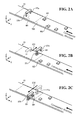
FIG. 2A is a first schematic perspective view of a robot system, illustrating a picking movement in a method according to a comparative example for picking a workpiece; -
FIG. 2B is a second schematic perspective view of the robot system, illustrating the picking movement in the comparative method for picking a workpiece; -
FIG. 2C is a third schematic perspective view of the robot system, illustrating the picking movement in the comparative method for picking a workpiece; -
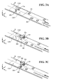
FIG. 3A is a first schematic perspective view of the robot system according to the embodiment, illustrating a basic picking movement in a method according to the embodiment for picking a workpiece; -
FIG. 3B is a second schematic perspective view of the robot system according to the embodiment, illustrating the basic picking movement in the method according to the embodiment for picking a workpiece; -
FIG. 3C is a third schematic perspective view of the robot system according to the embodiment, illustrating the basic picking movement in the method according to the embodiment for picking a workpiece; -
FIG. 4A is a first schematic perspective view of the robot system according to the embodiment, illustrating an exceptional picking movement in the method according to the embodiment for picking a workpiece; -
FIG. 4B is a second schematic perspective view of the robot system according to the embodiment, illustrating the exceptional picking movement in the method according to the embodiment for picking a workpiece; -
FIG. 4C is a third schematic perspective view of the robot system according to the embodiment, illustrating the exceptional picking movement in the method according to the embodiment for picking a workpiece; -
FIG. 5 is a block diagram illustrating the robot system according to the embodiment; and -
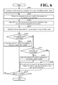
FIG. 6 is a flowchart of a procedure for processing performed by the robot system according to the embodiment. - A robot system and a method for picking a workpiece according to an embodiment of the present disclosure will be described in detail below with reference to the accompanying drawings. The following embodiments are provided for exemplary purposes only and are not intended to limit the present disclosure.
- An outline of a
robot system 1 according to the embodiment will be described with reference toFIGs. 1A to 1C .FIG. 1A is a schematic perspective view of arobot system 1 according to this embodiment, illustrating an arrangement configuration of therobot system 1.FIG. 1B is a schematic diagram illustrating one round of transfer movement.FIG. 1C is a schematic diagram illustrating a position of a robot hand in a basic posture in relation to positions of divided areas. - For ease of description,
FIG. 1A illustrates a three-dimensional orthogonal coordinate system including a Z axis with its vertically upward direction being assumed the positive direction. This orthogonal coordinate system may also be illustrated in some other drawings referred to in the following description. - As illustrated in
FIG. 1A , therobot system 1 according to this embodiment includes aconveyor 10, arobot 20, adetector 30, and acontroller 40. - The
conveyor 10 is a conveyance device that conveys workpieces W on aconveyance path 11 from the upstream side toward the downstream side. In this embodiment, theconveyor 10 is a belt conveyor. This configuration, however, should not be construed in a limiting sense. Theconveyor 10 may be any other conveyance device insofar as the conveyance device is capable of conveying the workpieces W in a predetermined conveyance direction. In this embodiment, the conveyance direction is the negative direction of the X axis. - The
robot 20 is an articulated robot secured on an installation object such as a ceiling, a wall, and a floor. Therobot 20 holds workpieces W conveyed on theconveyor 10 and transfers the workpieces W to another place. In this embodiment, therobot 20 transfers the workpieces W to aconveyor 50, which is parallel to the conveyor 10 (see thearrow 101 inFIG. 1A ). - The
robot 20 includes an armdistal end 21. To the armdistal end 21, the robot hand to hold the workpieces W is attached. - The robot hand includes a plurality of
holders support 22. Theholders support 22 is turnably disposed on the armdistal end 21 and supports the plurality ofholders - The
holders robot 20 holds a plurality of workpieces W using theholders robot 20 holds and moves the workpieces W to above theconveyor 50. Then, the suction force of the suction device is released to place the workpieces W onto theconveyor 50. - Specifically, as illustrated in
FIG. 1B , a plurality of workpieces W are sucked on both theholders robot 20 uses both theholders conveyor 10 to theconveyor 50 at once (see thearrow 102 inFIG. 1B ). - After a round of this transfer movement, the
robot 20 returns to its predetermined "basic posture". From the "basic posture", therobot 20 starts a next round of transfer movement to hold workpieces W. - As illustrated in
FIG. 1C , in the "basic posture", the robot hand is positioned above theconveyor 10 with theholders conveyor 10. The "width direction" is approximately perpendicular to the conveyance direction of the conveyor 10 (seeFIGs. 1A and1C ). - On the
conveyance path 11 of theconveyor 10, therobot 20 has a movable area WA. The movable area WA is divided in advance in the "width direction" into divided areas CA1 and CA2. Theholder 23a is allocated to the divided area CA1, since theholder 23a is closest of theholders robot 20 is in its "basic posture". Theholder 23b is allocated to the divided area CA2, since theholder 23b is closest of theholders robot 20 is in its "basic posture". This allocation is performed by anallocator 41c, which will be described later (seeFIG. 5 ). - Thus, the
holders robot 20 includes two holders, therobot 20 may include three or more holders. - The robot hand of the
robot 20 may be any other robot hand insofar as the robot hand is capable of holding the workpieces W. For example, therobot 20 may include a robot hand to clamp, instead of suck, to hold the workpieces W. - In this embodiment, the
robot 20 is a vertical articulated robot. This configuration, however, should not be construed in a limiting sense. Therobot 20 may be a horizontal articulated robot, a parallel link robot, an orthogonal robot, or any other robot insofar as the robot is capable of holding and transferring the workpieces W. - The
detector 30 is disposed at a further upstream position on theconveyor 10 than therobot 20. Thedetector 30 includes acamera 31, for example. Thecamera 31 picks up an image of a predetermined area on theconveyance path 11 to detect a conveyance situation in which the workpieces W are conveyed. The image picked up by thecamera 31 is output to thecontroller 40 through a communication network (not illustrated) such as a Local Area Network (LAN). - The
controller 40 is coupled in a communicable manner to various elements such as theconveyor 10, therobot 20, and thedetector 30. It is noted that any form of connection, wired or wireless, may be employed. Thecontroller 40 includes various control units, processors, and storages so as to control operations of the various elements coupled to thecontroller 40. - For example, based on a job program acquired through an input device (such as a programming pendant) or through an upper-level device, not illustrated, the
controller 40 generates a movement signal to cause therobot 20 to operate. Then, thecontroller 40 outputs the movement signal to therobot 20 so as to control the movement of therobot 20. - The movement signal is generated in the form of, for example, a pulse signal to each servomotor in each joint of the
robot 20. A specific configuration of thecontroller 40 will be described later with reference toFIG. 5 . - With the above-described configuration of the
robot system 1 according to this embodiment, thecamera 31 picks up an image on theconveyance path 11 of theconveyor 10. Based on the image picked up by thecamera 31, thecontroller 40 acquires a conveyance situation in which the workpiece W are conveyed on theconveyance path 11. - Based on the acquired conveyance situation, the
controller 40 makes an instruction to therobot 20 to make a transfer movement, which is to hold the workpieces W using theholders conveyor 50. In response to the instruction from thecontroller 40, therobot 20 performs the transfer movement. In the following description, the action of holding a workpiece W in transferring workpieces W, that is, taking a workpiece W from theconveyor 10 will be referred to as "picking". - Next, by referring to
FIGs. 2A to 4C , a method for picking a workpiece using therobot system 1 will be described in relation to a comparative method for picking a workpiece. -
FIGs. 2A to 2C are first to third schematic perspective views of the robot system, illustrating a picking movement in the comparative method for picking a workpiece. -
FIGs. 3A to 3C are first to third schematic perspective views of therobot system 1, illustrating a basic picking movement in the method according to this embodiment for picking a workpiece.FIGs. 4A to 4C are first to third schematic perspective views of therobot system 1, illustrating an exceptional picking movement in the method according to this embodiment for picking a workpiece. For convenience of description, like reference numerals designate corresponding or identical elements throughoutFIG. 2A to FIG. 4C . - As illustrated in
FIG. 2A , in the comparative method for picking a workpiece, a predetermined order is determined in advance for theholders conveyor 10. In this example, none of theholder holder 23b is the first to be used (see the dashed circle M1 inFIG. 2A ). - Specifically, as illustrated in
FIG. 2B , when a workpiece W1 conveyed on theconveyor 10 is partial to the positive direction of the Y axis, therobot 20 picks the workpiece W1 using theholder 23b even though theholder 23b is partial to the negative direction of the Y axis. Then, as illustrated inFIG. 2C , when a workpiece W2 conveyed on theconveyor 10 is partial to the negative direction of the Y axis, therobot 20 picks the workpiece W2 using theholder 23a even though theholder 23a is partial to the positive direction of the Y axis. - That is, in the comparative method for picking a workpiece, the
robot 20 may have to move over a long distance in the picking movement due to, for example, the positions of the workpieces W on the conveyor 10 (see thearrow 201 inFIG. 2B and thearrow 202 inFIG. 2C ). Because of the elongated distance of movement of therobot 20, the comparative method for picking a workpiece may degrade conveyance efficiency of the workpieces W. - In view of this, in the method according to this embodiment for picking a workpiece, the
holders - Specifically, as illustrated in
FIG. 3A , in the method according to this embodiment for picking a workpiece, theholder 23a is allocated to the divided area CA1 as theholder 23a's territory, and theholder 23b is allocated to the divided area CA2 as theholder 23b's territory. - As illustrated in
FIG. 3B , a workpiece W1 conveyed on theconveyor 10 is partial to the positive direction of the Y axis and enters the divided area CA1. Therobot 20 picks the workpiece W1 using theholder 23a considering that theholder 23a is similarly partial to the positive direction of the Y axis. As illustrated inFIG. 3C , a workpiece W2 conveyed on theconveyor 10 is partial to the negative direction of the Y axis and enters the divided area CA2. Therobot 20 picks the workpiece W2 using theholder 23b considering that theholder 23b is similarly partial to the negative direction of the Y axis. - Thus, the method according to this embodiment for picking a workpiece shortens the distance involved in the picking movement (see the
arrow 301 inFIG. 3B and thearrow 302 inFIG. 3C ), as compared with the comparative method for picking a workpiece. That is, the method according to this embodiment for picking a workpiece improves efficiency in the conveyance of the workpieces W, that is, ensures more efficient transfer of the workpieces W. -
FIGs. 3A to 3C illustrate a basic picking movement in the method according to this embodiment for picking a workpiece. It is possible for workpieces W to be continuously partial to one side of theconveyor 10. In this case, the method for picking a workpiece according to this embodiment uses an exceptional picking movement. - For example, as illustrated in
FIG. 4A , assume that workpieces W1 to W3 are continuously partial to the positive direction of the Y axis of theconveyor 10, that is, the workpieces W1 to W3 are about to enter the divided area CA1. - In this case, as illustrated in
FIG. 4B , the method according to this embodiment for picking a workpiece first uses the above-described basic picking movement to pick the workpiece W1, which has entered the divided area CA1, using theholder 23a. - Then, the workpiece W2 subsequently enters the divided area CA1 and is picked exceptionally by the
holder 23b when theholder 23b is not being used, even though theholder 23b is originally in charge of the divided area CA2 (see the dashed circle M2 inFIG. 4C ). - Thus, even when workpieces W are continuously partial to one side of the
conveyor 10, all the workpieces W are reliably transferred, without any one workpiece W being missed in picking. - The workpieces W1 and W2 in the state illustrated in
FIG. 4C are transferred to theconveyor 50. Then, a workpiece W3 and subsequent workpieces W are picked in the above-described basic picking movement. That is, in the method according to this embodiment for picking a workpiece, in the case where workpieces W are continuously partial to one side of theconveyor 10, the movement distance involved in the picking of these workpieces W temporarily increases (see thearrow 402 inFIG. 4C ). In the other cases, however, the basic picking movement is used (see thearrow 401 inFIG. 4B ). This configuration improves conveyance efficiency. - Next, by referring to
FIG. 5 , a block configuration of therobot system 1 according to this embodiment will be described.FIG. 5 is a block diagram illustrating therobot system 1 according to this embodiment. It is noted thatFIG. 5 only illustrates those components necessary for description of therobot system 1, omitting those components of general nature. - The following description by referring to
FIG. 5 will mainly focus on the internal configuration of thecontroller 40, and may occasionally simplify or omit the components that have been already described by referring to, for example,FIG. 1A . - As illustrated in
FIG. 5 , thecontroller 40 includes a control unit 41 and astorage 42. The control unit 41 includes a conveyor controller 41a, a dividedarea setter 41b, anallocator 41c, asituation acquirer 41d, and an instructor 41e. - The
storage 42 is a storage device such as a hard disk drive and a non-volatile memory, and includes dividedarea setting information 42a, dividedarea information 42b, andallocation information 42c. - It is noted that not all the elements of the
controller 40 illustrated inFIG. 5 need to be arranged within thesingle controller 40. Another possible embodiment is that at least one of the dividedarea setting information 42a, the dividedarea information 42b, and theallocation information 42c stored in thestorage 42 is stored in an inner memory of therobot 20. Still another possible embodiment is that at least one of the dividedarea setting information 42a, the dividedarea information 42b, and the allocation information 24c is stored in an upper-level device upper than thecontroller 40, and acquired as necessary from the upper-level device by thecontroller 40. - A non-limiting example of the control unit 41 is a Central Processing Unit (CPU) that is in charge of overall control of the
controller 40. The conveyor controller 41a controls theconveyor 10, which is arranged to pass through a movable area WA of therobot 20, to convey workpieces W to the movable area WA of therobot 20. - The divided
area setter 41b sets the imaginary divided areas CA1 and CA2 (seeFIGs. 1A and1C ) on theconveyor 10 based on the dividedarea setting information 42a, and stores the divided areas CA1 and CA2 as the dividedarea information 42b. - The divided
area setting information 42a is necessary information in setting the divided areas CA1 and CA2, and includes the position and dimensions of the movable area WA of therobot 20, the width of theconveyor 10, and the number of holders of the robot hand. - The divided
area information 42b includes a result of setting by the dividedarea setter 41b such as the positions and dimensions of the divided areas CA1 and CA2. - Based on the divided
area information 42b, theallocator 41c allocates theholders allocator 41c assigns theholders - Also, the
allocator 41c stores a result of the allocation as theallocation information 42c. That is, theallocation information 42c relates the divided areas CA1 and CA2 respectively to theholders - Based on an image received from the
camera 31, thesituation acquirer 41d acquires a conveyance situation in which the workpieces W are conveyed. While in this embodiment thedetector 30 includes thecamera 31, thedetector 30 may include any other device for the purpose of detecting the conveyance situation in which the workpieces W are conveyed. - For example, the
detector 30 may include photoelectric sensors and an encoder of theconveyor 10. Based on information received from these devices, thesituation acquirer 41d is also capable of acquiring a conveyance situation in which the workpieces W are conveyed. Thesituation acquirer 41d notifies the instructor 41e of a result of the acquisition. - In response to the result of the acquisition received from the
situation acquirer 41d, in response to availability of theholders holders allocation information 42c, the instructor 41e instructs therobot 20 to make a movement to transfer the workpieces W. - Specifically, unless the workpieces W are conveyed continuously in either the divided area CA1 or the divided area CA2, the instructor 41e instructs the
robot 20 to hold and transfer the workpieces W in the above-described basic picking movement (seeFIGs. 3A to 3C ). - Alternatively, when the workpieces W are conveyed continuously in either the divided area CA1 or the divided area CA2, the instructor 41e instructs the
robot 20 to hold and transfer the workpieces W in the above-described exceptional picking movement (seeFIGs. 4A to 4C ). - When one round of transfer movement is complete, the instructor 41e instructs the
robot 20 to take its basic posture. - In the description by referring to
FIG. 5 , the dividedarea setter 41b sets the divided areas CA1 and CA2 based on the dividedarea setting information 42a. This configuration, however, should not be construed in a limiting sense. Another possible embodiment is that the dividedarea setter 41b divides an image picked up by thecamera 31 into the divided areas CA1 and CA2 in the width direction of theconveyor 10, and stores the divided areas CA1 and CA2 as the dividedarea information 42b. - Next, by referring to
FIG. 6 , a procedure for processing performed by therobot system 1 according to this embodiment will be described.FIG. 6 is a flowchart of the procedure for processing performed by therobot system 1 according to this embodiment. - As illustrated in
FIG. 6 , thecontroller 40 controls theconveyor 10 to convey workpieces W through the movable area WA of the robot 20 (step S101). Theconveyor 10 is controlled by the conveyor controller 41a to convey the workpiece W until the completion of work. It will be readily appreciated that this embodiment is implementable without the control of changing the conveyance speed of the conveyor. - Next, the
detector 30 detects a conveyance situation in which the workpieces W are conveyed on the conveyor 10 (step S102). Then, based on the conveyance situation acquired by thesituation acquirer 41d, the instructor 41e identifies the divided area, CA1 or CA2, to which a workpiece W corresponds (step S103). - Next, the instructor 41e identifies the holder, 23a or 23b, that is allocated to the divided area, CA1 or CA2, of interest (step S104). For the sake of description, assume that the instructor 41e identifies the
holder 23a. - Then, the instructor 41e determines whether the identified
holder 23a is not being used (step S105). When theholder 23a is not being used ("Yes" at step S105), the instructor 41e operates therobot 20 to hold the workpiece W using theholder 23a (step S106). - When the
holder 23a is in use ("No" at step S105), the instructor 41e determines whether the other holder, namely, theholder 23b is not being used (step S107). - When the
holder 23b is not being used ("Yes" at step S107), the instructor 41e operates therobot 20 to hold the workpiece W using theholder 23b (step S108). - When the
holder 23b is in use ("No" at step S107), which means that both theholders robot 20 to transfer the workpieces W held by theholders conveyor 50, and then to hold the workpiece W using theholder 23a (step S109). - Then, a determination is made as to whether the work is complete (step S110). When the work is complete ("Yes" at step S110), the processing ends. When the work is not complete ("No" at step S110), the
controller 40 repeats the processing that starts from step S102. - As has been described hereinbefore, the robot system according to this embodiment includes the conveyor, the robot, and the controller. The conveyor conveys workpieces. The robot includes the plurality of holders to hold the workpieces.
- The controller controls the robot to make a movement to hold a workpiece conveyed on the conveyor using one of the holders and to transfer the workpiece to a predetermined place. The controller includes the divided area setter and the allocator.
- The divided area setter sets the plurality of divided areas on the conveyor in the width direction of the conveyor and stores the divided areas in the storage. The allocator allocates the holders respectively to the divided areas so as to hold the workpiece when the workpiece is conveyed in the divided areas.
- With this configuration, the robot system according to this embodiment ensures efficient transfer of the workpieces.
- In this embodiment, the robot makes the exceptional picking movement in an attempt to eliminate or minimize missed picking of the workpieces. This configuration, however, should not be construed in a limiting sense. Another possible embodiment is to add the control of changing the conveyance speed of the conveyor.
- Obviously, numerous modifications and variations of the present disclosure are possible in light of the above teachings. It is therefore to be understood that within the scope of the appended claims, the present disclosure may be practiced otherwise than as specifically described herein.
- 1
- Robot system
- 10
- Conveyor
- 11
- Conveyance path
- 20
- Robot
- 21
- Arm distal end
- 22
- Support
- 23a
- Holder
- 23b
- Holder
- 30
- Detector
- 31
- Camera
- 40
- Controller
- 41
- Control unit
- 41a
- Conveyor controller
- 41b
- Divided area setter
- 41c
- Allocator
- 41d
- Situation acquirer
- 41e
- Instructor
- 42
- Storage
- 42a
- Divided area setting information
- 42b
- Divided area information
- 42c
- Allocation information
- 50
- Conveyor
- CA1, CA2
- Divided area
- WA
- Movable area
Claims (6)
- A robot system (1), characterized by:a conveyor (10) configured to convey at least one workpiece;a robot (20) comprising a plurality of holders (23a, 23b) configured to hold the at least one workpiece; anda controller (40) configured to control the robot (20) to hold the at least one workpiece conveyed on the conveyor (10) and transfer the at least one workpiece to a predetermined place using at least one holder (23a, 23b) among the plurality of holders (23a, 23b), the controller (40) comprising:a divided area setter (41b) configured to set a plurality of divided areas on the conveyor (10) in a width direction of the conveyor (10), and configured to store the plurality of divided areas in a storage (42); andan allocator (41c) configured to allocate the plurality of holders (23a, 23b) respectively to the plurality of divided areas so as to hold the at least one workpiece when the at least one workpiece is conveyed in the plurality of divided areas.
- The robot system (1) according to claim 1, further comprising a detector (30) configured to detect a conveyance situation in which the at least one workpiece is conveyed on the conveyor (10),
wherein a first holder (23a, 23b) among the plurality of holders (23a, 23b) is allocated to a first divided area among the plurality of divided areas to hold the at least one workpiece when the at least one workpiece is conveyed in the first divided area, and
wherein when the detector (30) detects another workpiece being conveyed to the first divided area while the first holder (23a, 23b) is holding the at least one workpiece in the first divided area, and when a second holder (23b, 23a) that is among the plurality of holders (23b, 23a) and that is not allocated to the first divided area is not being used, the controller (40) is configured to control the robot (20) to hold the another workpiece in the first divided area using the second holder (23b, 23a). - The robot system (1) according to claim 1 or 2,
wherein the plurality of holders (23a, 23b) are parallel to each other relative to a robot hand of the robot (20), and
wherein when the robot (20) holds the at least one workpiece, the controller (40) is configured to control the robot (20) to take a basic posture in which the robot hand is positioned above the conveyor (10) with the plurality of holders (23a, 23b) aligned in a direction parallel to the width direction of the conveyor (10). - The robot system (1) according to claim 3, wherein when the robot (20) is in the basic posture, the allocator (41c) is configured to allocate one holder (23a, 23b) among the plurality of holders (23a, 23b) to one divided area among the plurality of divided areas that is closest to the one holder (23a, 23b).
- A method for picking a workpiece, characterized by:conveying at least one workpiece using a conveyor (10) through a movable area of a robot (20) comprising a plurality of holders (23a, 23b);detecting a conveyance situation in which the at least one workpiece is conveyed on the conveyor (10);identifying, based on the conveyance situation, a divided area to which the at least one workpiece corresponds from among a plurality of divided areas of the conveyor (10) that are divided in a width direction of the conveyor (10); andoperating the robot (20) to hold the at least one workpiece using one holder (23a, 23b) among the plurality of holders (23a, 23b) that is allocated to the divided area.
- The method according to claim 5, wherein when the detecting step detects another workpiece being conveyed to the divided area while the one holder (23a, 23b) is holding the workpiece in the divided area, and when another holder (23b, 23a) that is among the plurality of holders (23b, 23a) and that is not allocated to the divided area is not being used, the operating step comprises operating the robot (20) to hold the another workpiece in the divided area using the another holder (23b, 23a).
Applications Claiming Priority (1)
| Application Number | Priority Date | Filing Date | Title |
|---|---|---|---|
| JP2014190204A JP6715565B2 (en) | 2014-09-18 | 2014-09-18 | Robot system and work picking method |
Publications (1)
| Publication Number | Publication Date |
|---|---|
| EP2998076A1 true EP2998076A1 (en) | 2016-03-23 |
Family
ID=54140225
Family Applications (1)
| Application Number | Title | Priority Date | Filing Date |
|---|---|---|---|
| EP15183816.6A Ceased EP2998076A1 (en) | 2014-09-18 | 2015-09-04 | Robot system and method for picking workpiece |
Country Status (4)
| Country | Link |
|---|---|
| US (1) | US20160083199A1 (en) |
| EP (1) | EP2998076A1 (en) |
| JP (1) | JP6715565B2 (en) |
| CN (1) | CN105437249B (en) |
Cited By (4)
| Publication number | Priority date | Publication date | Assignee | Title |
|---|---|---|---|---|
| CN110216649A (en) * | 2018-03-02 | 2019-09-10 | 株式会社日立制作所 | The control method of robot manipulating task system and robot manipulating task system |
| CN110958425A (en) * | 2018-09-27 | 2020-04-03 | 佳能株式会社 | Information processing apparatus, information processing method, and system |
| US10692018B2 (en) | 2016-09-27 | 2020-06-23 | Fanuc Corporation | Machine learning device and machine learning method for learning optimal object grasp route |
| DE102017008832B4 (en) * | 2016-09-28 | 2020-10-01 | Fanuc Corporation | Conveyor device for taking out objects one by one in an optimal way |
Families Citing this family (21)
| Publication number | Priority date | Publication date | Assignee | Title |
|---|---|---|---|---|
| CN103748024B (en) * | 2011-06-07 | 2017-02-15 | 康尔富盛德国326有限公司 | Device for separating piece goods to be stored in an automated warehouse |
| ITUB20160315A1 (en) * | 2016-01-27 | 2017-07-27 | Ct Pack Srl | METHOD FOR TRANSFER OF ARTICLES. |
| CN105775726B (en) * | 2016-04-13 | 2017-12-22 | 英华达(南京)科技有限公司 | Pickup and apparatus for placing and its application process |
| EP3453053B1 (en) * | 2016-05-06 | 2021-03-10 | Applied Materials Italia Srl | Apparatus for aligning a solar cell element, system for use in the manufacture of a solar cell arrangement, and method for aligning a solar cell element |
| EP3525990B1 (en) * | 2016-10-12 | 2022-11-30 | ABB Schweiz AG | A method and a system for controlling a velocity of a conveyance path |
| JP6589847B2 (en) * | 2016-12-26 | 2019-10-16 | 株式会社ダイフク | Material loading equipment |
| US11305432B2 (en) * | 2017-01-12 | 2022-04-19 | Fuji Corporation | Work machine and pick-up position selection method |
| CN110636922B (en) | 2017-05-16 | 2023-03-21 | Abb瑞士股份有限公司 | Method and control system for controlling a sequence of movements of a robot |
| CN107265114A (en) * | 2017-06-19 | 2017-10-20 | 太仓弘杉环保科技有限公司 | A kind of method of work of high-efficiency and energy-saving type feeding robot |
| CN107097230A (en) * | 2017-06-19 | 2017-08-29 | 苏州诚晟信息技术有限公司 | A kind of energy saving and environment friendly feeding robot |
| CN107088885A (en) * | 2017-06-19 | 2017-08-25 | 苏州诚晟信息技术有限公司 | A kind of feeding robot and its method of work with positioning function |
| JP6275910B1 (en) * | 2017-09-26 | 2018-02-07 | 大和エンジニアリング株式会社 | Suction head |
| JP6894353B2 (en) * | 2017-11-21 | 2021-06-30 | 花王株式会社 | Goods delivery unit |
| JP6737827B2 (en) * | 2018-03-29 | 2020-08-12 | ファナック株式会社 | Control device and control method for collaborative robot |
| JP7363100B2 (en) * | 2019-05-28 | 2023-10-18 | 日本電気硝子株式会社 | Pick-up device and workpiece transport method |
| KR102288818B1 (en) * | 2020-08-25 | 2021-08-12 | 주식회사 쎄크 | X-ray inspection apparatus and x-ray inspection system |
| JP7598627B2 (en) * | 2021-01-19 | 2024-12-12 | 株式会社イシダ | Item stacking device |
| JP7578007B2 (en) | 2021-01-29 | 2024-11-06 | セイコーエプソン株式会社 | Robot control method and robot system |
| CN112938407B (en) * | 2021-03-22 | 2022-08-02 | 珠海格力智能装备有限公司 | Gripping device and gripping method |
| CN113664862B (en) * | 2021-10-25 | 2021-12-31 | 江苏中昇电子科技有限公司 | Manipulator is used in production of communication equipment casing |
| WO2025144622A1 (en) * | 2023-12-27 | 2025-07-03 | Assurant, Inc. | Robot enabled mobile device manipulation system, method, and apparatus |
Citations (5)
| Publication number | Priority date | Publication date | Assignee | Title |
|---|---|---|---|---|
| US5040056A (en) * | 1990-01-29 | 1991-08-13 | Technistar Corporation | Automated system for locating and transferring objects on a conveyor belt |
| JPH08336784A (en) | 1995-06-09 | 1996-12-24 | Shibuya Kogyo Co Ltd | Article handling device |
| US20120323363A1 (en) * | 2011-06-20 | 2012-12-20 | Kabushiki Kaisha Yaskawa Denki | Robot system |
| US20120323357A1 (en) * | 2011-06-20 | 2012-12-20 | Kabushiki Kaisha Yaskawa Denki | Picking system |
| JP2014104524A (en) * | 2012-11-27 | 2014-06-09 | Shibuya Kogyo Co Ltd | Article processing system |
Family Cites Families (15)
| Publication number | Priority date | Publication date | Assignee | Title |
|---|---|---|---|---|
| US3774778A (en) * | 1971-06-09 | 1973-11-27 | R Flaig | Case packing machine |
| US4456961A (en) * | 1982-03-05 | 1984-06-26 | Texas Instruments Incorporated | Apparatus for teaching and transforming noncoincident coordinate systems |
| JP3314890B2 (en) * | 1993-04-23 | 2002-08-19 | 澁谷工業株式会社 | Article alignment device |
| US20060182607A1 (en) * | 2005-01-18 | 2006-08-17 | Clark Jason A | Method and apparatus for depalletizing bagged products |
| JP4864363B2 (en) * | 2005-07-07 | 2012-02-01 | 東芝機械株式会社 | Handling device, working device, and program |
| PL1882652T3 (en) * | 2006-07-26 | 2008-12-31 | Indag Gesellschaft Fuer Ind Mbh & Co Betriebs Kg | Gripping device |
| JP2008296330A (en) * | 2007-05-31 | 2008-12-11 | Fanuc Ltd | Robot simulation device |
| US8790064B2 (en) * | 2008-03-12 | 2014-07-29 | Schuler Automation Gmbh & Co. Kg. | Device and method for aligning the position of plate-shaped parts |
| JP2010125583A (en) * | 2008-12-01 | 2010-06-10 | Seiko Epson Corp | Robot arm device, and control method and control program of the robot arm device |
| JP5810562B2 (en) * | 2011-03-15 | 2015-11-11 | オムロン株式会社 | User support device directed to image processing system, program thereof, and image processing device |
| JP5316580B2 (en) * | 2011-05-17 | 2013-10-16 | 株式会社安川電機 | Robot system |
| JP5464177B2 (en) * | 2011-06-20 | 2014-04-09 | 株式会社安川電機 | Picking system |
| US8868231B2 (en) * | 2011-08-10 | 2014-10-21 | Xerox Corporation | Flexible production collating system |
| JP6116879B2 (en) * | 2012-12-03 | 2017-04-19 | 株式会社イシダ | Adsorption conveyance device and adsorption conveyance method |
| US9272421B2 (en) * | 2013-01-07 | 2016-03-01 | Milos Misha Subotincic | Visually controlled end effector |
-
2014
- 2014-09-18 JP JP2014190204A patent/JP6715565B2/en active Active
-
2015
- 2015-09-04 EP EP15183816.6A patent/EP2998076A1/en not_active Ceased
- 2015-09-15 CN CN201510587169.6A patent/CN105437249B/en active Active
- 2015-09-17 US US14/857,763 patent/US20160083199A1/en not_active Abandoned
Patent Citations (5)
| Publication number | Priority date | Publication date | Assignee | Title |
|---|---|---|---|---|
| US5040056A (en) * | 1990-01-29 | 1991-08-13 | Technistar Corporation | Automated system for locating and transferring objects on a conveyor belt |
| JPH08336784A (en) | 1995-06-09 | 1996-12-24 | Shibuya Kogyo Co Ltd | Article handling device |
| US20120323363A1 (en) * | 2011-06-20 | 2012-12-20 | Kabushiki Kaisha Yaskawa Denki | Robot system |
| US20120323357A1 (en) * | 2011-06-20 | 2012-12-20 | Kabushiki Kaisha Yaskawa Denki | Picking system |
| JP2014104524A (en) * | 2012-11-27 | 2014-06-09 | Shibuya Kogyo Co Ltd | Article processing system |
Non-Patent Citations (1)
| Title |
|---|
| YANJIANG HUANG ET AL: "Part dispatching rule-based multi-robot coordination in pick-and-place task", ROBOTICS AND BIOMIMETICS (ROBIO), 2012 IEEE INTERNATIONAL CONFERENCE ON, IEEE, 11 December 2012 (2012-12-11), pages 1887 - 1892, XP032353054, ISBN: 978-1-4673-2125-9, DOI: 10.1109/ROBIO.2012.6491243 * |
Cited By (9)
| Publication number | Priority date | Publication date | Assignee | Title |
|---|---|---|---|---|
| US10692018B2 (en) | 2016-09-27 | 2020-06-23 | Fanuc Corporation | Machine learning device and machine learning method for learning optimal object grasp route |
| DE102017008836B4 (en) * | 2016-09-27 | 2020-09-24 | Fanuc Corporation | Machine learning device and machine learning method for learning an optimal object gripping path |
| DE102017008832B4 (en) * | 2016-09-28 | 2020-10-01 | Fanuc Corporation | Conveyor device for taking out objects one by one in an optimal way |
| CN110216649A (en) * | 2018-03-02 | 2019-09-10 | 株式会社日立制作所 | The control method of robot manipulating task system and robot manipulating task system |
| EP3534230A3 (en) * | 2018-03-02 | 2020-02-26 | Hitachi, Ltd. | Robot work system and method of controlling robot work system |
| CN110216649B (en) * | 2018-03-02 | 2022-05-10 | 株式会社日立制作所 | Robot operating system and control method of robot operating system |
| CN110958425A (en) * | 2018-09-27 | 2020-04-03 | 佳能株式会社 | Information processing apparatus, information processing method, and system |
| CN110958425B (en) * | 2018-09-27 | 2021-07-23 | 佳能株式会社 | Information processing apparatus, information processing method, and system |
| US11541545B2 (en) | 2018-09-27 | 2023-01-03 | Canon Kabushiki Kaisha | Information processing apparatus, information processing method, and system |
Also Published As
| Publication number | Publication date |
|---|---|
| CN105437249B (en) | 2017-11-10 |
| JP2016060002A (en) | 2016-04-25 |
| CN105437249A (en) | 2016-03-30 |
| JP6715565B2 (en) | 2020-07-01 |
| US20160083199A1 (en) | 2016-03-24 |
Similar Documents
| Publication | Publication Date | Title |
|---|---|---|
| US20160083199A1 (en) | Robot system and method for picking workpiece | |
| EP2998077B1 (en) | Robot system, robot apparatus, and method for picking workpiece | |
| JP5464176B2 (en) | Picking system | |
| JP5786896B2 (en) | Work detection device, robot system, workpiece manufacturing method and workpiece detection method | |
| US10858188B2 (en) | Gripping device and conveying apparatus | |
| JP5930037B2 (en) | Robot system and article transfer method | |
| CN102837316B (en) | picking up system | |
| CN105314310B (en) | Cargo handling apparatus and methods | |
| US20140079524A1 (en) | Robot system and workpiece transfer method | |
| CN102785238B (en) | robot system | |
| EP2578366A2 (en) | Robot apparatus, robot system, and method for producing a to-be-processed material | |
| EP2708333A2 (en) | Robot apparatus for transferring to-be processed objects | |
| WO2014013608A1 (en) | Robot system and article transfer method | |
| JP6011278B2 (en) | Article processing system | |
| EP2711143A2 (en) | Robot system and article manufacturing method | |
| CN104203493A (en) | Production system and manufacturing method for processed products | |
| JP2018203527A (en) | Cargo handling device, and operation method of cargo handling device | |
| TW201641234A (en) | Robot system and robot apparatus | |
| WO2020049768A1 (en) | Manipulator and mobile robot | |
| CN116918851B (en) | Systems and methods for automatically suspending poultry on the carrier of a conveyor. | |
| JP2006160416A (en) | Method and apparatus for aligning the direction of an article | |
| JP2017056528A (en) | Transfer system and transfer method | |
| JP6863660B2 (en) | Wire harness manufacturing equipment | |
| JP2019108157A (en) | Retainer, system and method for container supply | |
| JP7343382B2 (en) | Work supply device |
Legal Events
| Date | Code | Title | Description |
|---|---|---|---|
| PUAI | Public reference made under article 153(3) epc to a published international application that has entered the european phase |
Free format text: ORIGINAL CODE: 0009012 |
|
| AK | Designated contracting states |
Kind code of ref document: A1 Designated state(s): AL AT BE BG CH CY CZ DE DK EE ES FI FR GB GR HR HU IE IS IT LI LT LU LV MC MK MT NL NO PL PT RO RS SE SI SK SM TR |
|
| AX | Request for extension of the european patent |
Extension state: BA ME |
|
| 17P | Request for examination filed |
Effective date: 20160412 |
|
| RBV | Designated contracting states (corrected) |
Designated state(s): AL AT BE BG CH CY CZ DE DK EE ES FI FR GB GR HR HU IE IS IT LI LT LU LV MC MK MT NL NO PL PT RO RS SE SI SK SM TR |
|
| 17Q | First examination report despatched |
Effective date: 20181017 |
|
| APBK | Appeal reference recorded |
Free format text: ORIGINAL CODE: EPIDOSNREFNE |
|
| APBN | Date of receipt of notice of appeal recorded |
Free format text: ORIGINAL CODE: EPIDOSNNOA2E |
|
| APBR | Date of receipt of statement of grounds of appeal recorded |
Free format text: ORIGINAL CODE: EPIDOSNNOA3E |
|
| APAF | Appeal reference modified |
Free format text: ORIGINAL CODE: EPIDOSCREFNE |
|
| APBT | Appeal procedure closed |
Free format text: ORIGINAL CODE: EPIDOSNNOA9E |
|
| STAA | Information on the status of an ep patent application or granted ep patent |
Free format text: STATUS: THE APPLICATION HAS BEEN REFUSED |
|
| 18R | Application refused |
Effective date: 20200921 |