EP2998054A1 - Cutting device - Google Patents
Cutting device Download PDFInfo
- Publication number
- EP2998054A1 EP2998054A1 EP14185535.3A EP14185535A EP2998054A1 EP 2998054 A1 EP2998054 A1 EP 2998054A1 EP 14185535 A EP14185535 A EP 14185535A EP 2998054 A1 EP2998054 A1 EP 2998054A1
- Authority
- EP
- European Patent Office
- Prior art keywords
- cutting device
- grinder
- cutting
- assembly
- pipe
- Prior art date
- Legal status (The legal status is an assumption and is not a legal conclusion. Google has not performed a legal analysis and makes no representation as to the accuracy of the status listed.)
- Withdrawn
Links
Images




Classifications
-
- B—PERFORMING OPERATIONS; TRANSPORTING
- B23—MACHINE TOOLS; METAL-WORKING NOT OTHERWISE PROVIDED FOR
- B23D—PLANING; SLOTTING; SHEARING; BROACHING; SAWING; FILING; SCRAPING; LIKE OPERATIONS FOR WORKING METAL BY REMOVING MATERIAL, NOT OTHERWISE PROVIDED FOR
- B23D45/00—Sawing machines or sawing devices with circular saw blades or with friction saw discs
- B23D45/12—Sawing machines or sawing devices with circular saw blades or with friction saw discs with a circular saw blade for cutting tubes
- B23D45/128—Sawing machines or sawing devices with circular saw blades or with friction saw discs with a circular saw blade for cutting tubes with the tool introduced into the tubes and cutting from the inside outwards
Definitions
- the present invention generally relates to pipelines maintenance and renovation. More in particular, the present invention relates to a cutting device, preferably employed to be inserted and advanced into a pipeline and operate a cutting of the same from the inside at a desired position.
- the cooling air distribution pipework is generally located in the inside of the plenum between two consecutive compressor vane carriers.
- the lifetime of the pipeline is limited due to a number of factors, and breakage of the cooling air pipeline can occur.
- the cutting device is adapted to be introduced and advanced into the pipe in order to provide a cutting operation from the inside.
- the cutting device is movable within the pipe by means of one or more feeding wires connected thereto to provide a remote control means of the device.
- the device comprises a grinder assembly movable between a resting position and an operative position, a swivel mechanism configured to orbit the grinder assembly during the cutting around a longitudinal axis of the device and a clamping assembly configured to align the cutting device inside the pipe, when located at the desired cutting position.
- the feeding wires comprise a grinder wire configured to remotely operate the grinder between the operating and resting positions.
- the grinder assembly comprises a cutting disc mounted on a sled.
- the grinder assembly comprises a compressed air feeding mechanism.
- the feeding wires comprise a first compressed air supply wire, associated to the compressed air feeding mechanism for operating the grinder assembly.
- the feeding wires comprise a swivel wire configured to remotely operate the swivel mechanism.
- the clamping assembly comprises two rows of retractable pistons; each row comprising at least three pistons located angularly equidistant at a common axial position along the longitudinal axis A.
- the clamping assembly comprises a compressed air circuit configured to operate the retractable pistons.
- the feeding wires comprise a second air supply wire associated to the compressed air circuit for operating the retractable pistons.
- the cutting device is advanced, power fed, and operated by means of the feeding wires which are connected to the device on one side only. In fact, for this type of applications, access from the opposite side may not be granted.
- Radial feed mechanism must have enough travel to allow the pipe to be completely cut through with cutting disc, in other words the operative position of the grinder assembly must extend radially of the right amount such to reach and cut the surrounding pipe.
- a reduction gear may be installed to carefully swivel the grinder for approximately 380°, in order to ensure a complete cut of the broken pipe.
- Debris (grinding dust) created in the engine are small enough to pass through the cooling channels without consequential damage to inner parts.
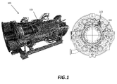
- FIG. 1 it is showed a gas turbine generally referred to with the numeral 100.
- a longitudinal section of the gas turbine with emphasis on an area 101 which indicates a plenum of the machine where the breakage of a compensator pipe of the air distribution pipework can occur.
- a transversal section of the machine where the compensator pipe is indicated with numeral 102.
- the section also shows an extraction flange 103 through which the compensator 102 is reachable if breakage occurs.
- the area 101 is shown in a perspective view. On the left it is depicted the compensator 102 before breakage, while on the right it is shown a new compensator fit in the same position after the cutting of the broken portion has been executed.
- FIG. 3 it is shown a cutting device 1 according to the present invention.
- the figure shows the cutting device 1 with all its constituent parts visible.
- the cutting device 1 defines altogether an elongated body having a longitudinal axis A and two opposite sides, extending radially, generally indicated with 11 and 12.
- the elongated body is shaped such to be adapted for insertion into the pipe to be cut from the inside.
- the cutting device comprises a grinder assembly 2 which is, as will be explained below, movable between a resting position and an operative position, the latter extending radially outwards with respect to the longitudinal axis A.
- the cutting device 1 is inserted into the pipe to be cut with the grinder assembly 2 in the resting position, and it is moved to the operating position when the device 1 has reached the correct location along the pipe to operate the cutting.
- the cutting device 1 further comprises a swivel mechanism 3, configured to turn the grinder assembly 2 around the longitudinal axis A when arranged in the operative position, in order to cut a surrounding pipe (not shown in the figure).
- the grinder assembly 2 comprises a cutting disc 25 mounted on a sled 26. More in particular, the cutting disc 25 is operated by a compressed air feeding mechanism, generally indicated in the figure with the numeral 27.
- the cutting device 1 also comprises a clamping assembly 4, configured to centre the device 1 into the pipe.
- the clamping assembly 4 comprises two rows 41 and 42 of retractable pistons. Each row comprises three pistons (in the figure only pistons 411 and 412 of row 41 and pistons 421 and 422 of row 42 are visible) located angularly equidistant at a common axial position along the longitudinal axis A. Each piston is then spaced 120 degrees from the other two along the same row.
- the clamping assembly 4 comprises a compressed air circuit configured to operate the retractable pistons which positions and centres the device inside the pipe for operating a complete cut.
- clamping assembly 4 is operated by a compressed air circuit.
- the cutting device 1 comprises feeding wires, generally indicated with the reference number 5, which are all connected to a common side 11 of the elongated body.
- the feeding wires 5 are configured such to provide means for moving the cutting device 1 through the pipe.
- the feeding wires may all be grouped into a single common external wire, to provide an even easier and more suitable means for advancing the device 1 inside the pipe and to take it back once the cutting has been executed (embodiment not shown).
- the wires are connected to the elongated body on one side only, this enables a total control of the cutting device 1 in remote downstream or upstream the cutting position.
- the feeding wires 5 comprise a grinder wire 51, configured to remotely operate the grinder assembly 2 in order to move it from the resting position to the operative position and vice versa.
- the feeding wires 5 also comprise a swivel wire 53 associated to the swivel mechanism 3, as it will be explained below.
- the feeding wires 5 comprise an air supply wire 52 associated to the compressed air feeding mechanism 27 which operates the grinder assembly 2, and a second air supply wire 54 which, in turn, operates the compressed air circuit for activating the retractable pistons of the clamping assembly 4.
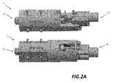
- the cutting device 1 is shown in an assembled configuration in a front and rear views.
- FIG 4 shows more in particular the grinder assembly 2 and its constituent parts.
- the grinder wire (not shown in the figure) is configured to remotely operate a threaded bar 21 to which it is connected.
- the feed guide 22 is connected to the grinder assembly 2, and more specifically to the sled 26, by means of a bracket 23.
- the bracket 23 has a first end 231 hinged to the sled 26 and a second end 232 hinged to the feed guide 22.
- the rotation given to the grinder wire in one sense triggers the rotation of the threaded bar 21 which, in turn, commands the travel of the feed guide 22 along the bar 21.
- the sled 26 which carries the cutting disc 25, is moved by the hinged bracket 23 along guides 26 arranged in a radial direction. So, the rotation of the grinder wire in one sense (depending on the type of the tread) determines the travel of the feed guide 22 in the direction indicated by arrow O. This causes the sled 26 to extend radially outwards, thus moving the grinder assembly 2 into the operating position. In this configuration, the cutting disc 25 is faced against the walls of the surrounding pipe (not shown) to be cut. In the same way, rotating the grinder wire in the opposite direction causes the feed guide to travel in the direction shown by arrow R of the figure, which causes the sled 26 to move back into the resting position, which allows the advancement of the cutting device within the pipe.
- swivel mechanism 3 comprises a gear box 31.
- the gear box 31 comprises a first gear wheel 311 integral to the grinder assembly 2, which is configured to orbit around a second gear wheel 312 integral to the clamping assembly (not shown).
- the swivel wire (not shown in the figure) is configured to operate, by its rotation, the first gear wheel 311 be means of a connection bar 313.
- the rotation of the first great wheel 311 determines the orbiting of the same around the second gear wheel 312. Therefore, the grinder assembly 2 is capable of rotating around the longitudinal axis for executing the cutting.
Landscapes
- Engineering & Computer Science (AREA)
- Mechanical Engineering (AREA)
- Finish Polishing, Edge Sharpening, And Grinding By Specific Grinding Devices (AREA)
Abstract
The present invention generally relates to pipelines maintenance and renovation. More in particular, the present invention relates to a cutting device (1), preferably employed to be inserted and advanced into a pipeline and operate a cutting of the same from the inside at a desired position. The cutting device is movable within the pipe by means of one or more feeding wires (5) connected thereto to provide a remote control means of the device. The device comprises a grinder aasembly (2) movable between a resting position and an operative position, a swivel mechanism (3) configured to orbit the grinder during the cutting around a longitudinal axis of the device and a clamping assembly (4) configured to align the cutting device (1) inside the pipe, when located at the desired cutting position.
Description
- The present invention generally relates to pipelines maintenance and renovation. More in particular, the present invention relates to a cutting device, preferably employed to be inserted and advanced into a pipeline and operate a cutting of the same from the inside at a desired position.
- In conventional gas turbines, the cooling air distribution pipework is generally located in the inside of the plenum between two consecutive compressor vane carriers.
- As well known, the lifetime of the pipeline is limited due to a number of factors, and breakage of the cooling air pipeline can occur.
- In case of rupture of the compensator within the cooling air distribution pipework, according to the current practise it is necessary to replace the pipe by removing the engine outer casing including the external pipe work, upper lances and burners. Such operation has very important costs, as it entails several days of production loss since the machine needs to be stopped. The cost can also vary depending on the particular location. Therefore, disassembling the engine to intervene for rectifying the broken pipe usually involves high costs to bear.
- It is an object of the present invention to solve the aforementioned technical problems with reference to the state of the art by providing a cutting device as substantially defined in
independent claim 1. - Preferred embodiments are defined in correspondent dependent claims.
- As it will appear clear from the detailed description of some exemplary, and not limiting, preferred embodiments of the invention, the cutting device is adapted to be introduced and advanced into the pipe in order to provide a cutting operation from the inside. The cutting device is movable within the pipe by means of one or more feeding wires connected thereto to provide a remote control means of the device. More in particular, the device comprises a grinder assembly movable between a resting position and an operative position, a swivel mechanism configured to orbit the grinder assembly during the cutting around a longitudinal axis of the device and a clamping assembly configured to align the cutting device inside the pipe, when located at the desired cutting position.
- According to an aspect of the invention, the feeding wires comprise a grinder wire configured to remotely operate the grinder between the operating and resting positions.
- According to a further aspect of the invention, the grinder assembly comprises a cutting disc mounted on a sled.
- According to a further aspect of the invention, the grinder assembly comprises a compressed air feeding mechanism.
- According to an aspect of the invention, the feeding wires comprise a first compressed air supply wire, associated to the compressed air feeding mechanism for operating the grinder assembly.
- According to a further preferred aspect of the invention, the feeding wires comprise a swivel wire configured to remotely operate the swivel mechanism.
- According to a further preferred aspect of the invention, the clamping assembly comprises two rows of retractable pistons; each row comprising at least three pistons located angularly equidistant at a common axial position along the longitudinal axis A. Preferably, the clamping assembly comprises a compressed air circuit configured to operate the retractable pistons.
- According to a further aspect of the invention, the feeding wires comprise a second air supply wire associated to the compressed air circuit for operating the retractable pistons.
- In case of pipe breakage inside the plenum of the machine, it is necessary to remove the upper section of the cooling air pipework on a closed engine through the extraction flange, and then cut the remaining broken end of the pipe from the inside. After insertion of the cutting device inside the pipe to be cut and removed, the latter is advanced up to the desired location. After the cutting is completed, the cutting device is retaken by means of the feeding wires and so is the cut pipe, which is carried by the cutting device as the grinder assembly extends radially outward and has a radius which is greater than the radius of the pipe.
- After the broken pipe is cut and removed, it is possible to proceed with the installation of a new female-male cooling air pipeline to the compressor vane carrier.
- The cutting device is advanced, power fed, and operated by means of the feeding wires which are connected to the device on one side only. In fact, for this type of applications, access from the opposite side may not be granted.
- Radial feed mechanism must have enough travel to allow the pipe to be completely cut through with cutting disc, in other words the operative position of the grinder assembly must extend radially of the right amount such to reach and cut the surrounding pipe.
- A reduction gear may be installed to carefully swivel the grinder for approximately 380°, in order to ensure a complete cut of the broken pipe.
- Debris (grinding dust) created in the engine are small enough to pass through the cooling channels without consequential damage to inner parts.
- The foregoing objects and many of the attendant advantages of this invention will become more readily appreciated as the same becomes better understood by reference to the following detailed description when taken in conjunction with the accompanying drawings, wherein:
-
Figure 1 shows a longitudinal and transversal section of a gas turbine where the cooling air distribution pipework is located; -
Figure 1A shows particulars offigure 1 before and after the cutting of a broken pipe has been executed; -
Figure 2 shows a perspective view of thecutting device 1 according to the present invention; -
Figure 2A shows the cutting device offigure 1 in a front and rear assembled view. -
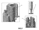
Figure 3 and4 show various particulars of the grinder assembly of the cutting device according to the invention; -
Figure 5 shows various particulars of the swivel mechanism of the cutting device according to the invention; - With reference to
figure 1 , it is showed a gas turbine generally referred to with thenumeral 100. On the left it is depicted a longitudinal section of the gas turbine with emphasis on anarea 101 which indicates a plenum of the machine where the breakage of a compensator pipe of the air distribution pipework can occur. With reference to the right part of the figure, it is shown a transversal section of the machine, where the compensator pipe is indicated withnumeral 102. The section also shows anextraction flange 103 through which thecompensator 102 is reachable if breakage occurs. - With reference to
figure 1A thearea 101 is shown in a perspective view. On the left it is depicted thecompensator 102 before breakage, while on the right it is shown a new compensator fit in the same position after the cutting of the broken portion has been executed. - Making now reference to next
figure 3 , it is shown acutting device 1 according to the present invention. In particular, the figure shows thecutting device 1 with all its constituent parts visible. - The
cutting device 1 defines altogether an elongated body having a longitudinal axis A and two opposite sides, extending radially, generally indicated with 11 and 12. The elongated body is shaped such to be adapted for insertion into the pipe to be cut from the inside. - More in particular, the cutting device comprises a
grinder assembly 2 which is, as will be explained below, movable between a resting position and an operative position, the latter extending radially outwards with respect to the longitudinal axis A. Thecutting device 1 is inserted into the pipe to be cut with thegrinder assembly 2 in the resting position, and it is moved to the operating position when thedevice 1 has reached the correct location along the pipe to operate the cutting. - The
cutting device 1 further comprises aswivel mechanism 3, configured to turn thegrinder assembly 2 around the longitudinal axis A when arranged in the operative position, in order to cut a surrounding pipe (not shown in the figure). - The
grinder assembly 2 comprises acutting disc 25 mounted on asled 26. More in particular, thecutting disc 25 is operated by a compressed air feeding mechanism, generally indicated in the figure with thenumeral 27. - The technical knowledge necessary to implement
such cutting disc 25 operated by a compressed air feeding mechanism is considered known to those who are skilled in the art and therefore a detailed description won't herein be given. - The
cutting device 1 also comprises aclamping assembly 4, configured to centre thedevice 1 into the pipe. - In this preferred and not limiting embodiment, the
clamping assembly 4 comprises tworows pistons row 41 andpistons row 42 are visible) located angularly equidistant at a common axial position along the longitudinal axis A. Each piston is then spaced 120 degrees from the other two along the same row. Theclamping assembly 4 comprises a compressed air circuit configured to operate the retractable pistons which positions and centres the device inside the pipe for operating a complete cut. The configuration shown in the described embodiment of two rows, each row comprising three pistons angularly equidistant from each other, shows the minimum number of pistons necessary to achieve the centring and the alignment of the cutting device inside the pipe along its longitudinal axis A. - Preferably,
clamping assembly 4 is operated by a compressed air circuit. - Similarly to the compressed air feeding mechanism for operating the
grinder assembly 2, the compressed air circuit for operating the clamping assembly is considered to be known by those who are skilled in the art, and therefore a detailed description won't herein be given. Furthermore, thecutting device 1 comprises feeding wires, generally indicated with the reference number 5, which are all connected to acommon side 11 of the elongated body. Advantageously, the feeding wires 5 are configured such to provide means for moving thecutting device 1 through the pipe. Preferably, the feeding wires may all be grouped into a single common external wire, to provide an even easier and more suitable means for advancing thedevice 1 inside the pipe and to take it back once the cutting has been executed (embodiment not shown). As the wires are connected to the elongated body on one side only, this enables a total control of thecutting device 1 in remote downstream or upstream the cutting position. - The feeding wires 5 comprise a
grinder wire 51, configured to remotely operate thegrinder assembly 2 in order to move it from the resting position to the operative position and vice versa. - The feeding wires 5 also comprise a
swivel wire 53 associated to theswivel mechanism 3, as it will be explained below. - Moreover, the feeding wires 5 comprise an
air supply wire 52 associated to the compressedair feeding mechanism 27 which operates thegrinder assembly 2, and a secondair supply wire 54 which, in turn, operates the compressed air circuit for activating the retractable pistons of the clampingassembly 4. - With reference now to following
figure 2A , thecutting device 1 is shown in an assembled configuration in a front and rear views. - With reference to
figure 3 , different parts of the grinder assembly are shown. In particular, in the figure it is shown thecutting disc 25, which is mounted on thesled 26. - Next
figure 4 shows more in particular thegrinder assembly 2 and its constituent parts. - The grinder wire (not shown in the figure) is configured to remotely operate a threaded
bar 21 to which it is connected. The rotation of thebar 21, enabled by the rotation of the grinder wire, triggers the travel of a threadedfeed guide 22. Thefeed guide 22 is connected to thegrinder assembly 2, and more specifically to thesled 26, by means of abracket 23. Thebracket 23 has afirst end 231 hinged to thesled 26 and asecond end 232 hinged to thefeed guide 22. The rotation given to the grinder wire in one sense triggers the rotation of the threadedbar 21 which, in turn, commands the travel of thefeed guide 22 along thebar 21. When thefeed guide 22 is moved along the direction of arrow O, as indicated in the figure, thesled 26 which carries thecutting disc 25, is moved by the hingedbracket 23 alongguides 26 arranged in a radial direction. So, the rotation of the grinder wire in one sense (depending on the type of the tread) determines the travel of thefeed guide 22 in the direction indicated by arrow O. This causes thesled 26 to extend radially outwards, thus moving thegrinder assembly 2 into the operating position. In this configuration, thecutting disc 25 is faced against the walls of the surrounding pipe (not shown) to be cut. In the same way, rotating the grinder wire in the opposite direction causes the feed guide to travel in the direction shown by arrow R of the figure, which causes thesled 26 to move back into the resting position, which allows the advancement of the cutting device within the pipe. - Lastly, with reference to the following
figure 5 , theswivel mechanism 3 is shown in greater detail. - Preferably,
swivel mechanism 3 comprises agear box 31. Thegear box 31 comprises afirst gear wheel 311 integral to thegrinder assembly 2, which is configured to orbit around asecond gear wheel 312 integral to the clamping assembly (not shown). - The swivel wire (not shown in the figure) is configured to operate, by its rotation, the
first gear wheel 311 be means of aconnection bar 313. The rotation of the firstgreat wheel 311 determines the orbiting of the same around thesecond gear wheel 312. Therefore, thegrinder assembly 2 is capable of rotating around the longitudinal axis for executing the cutting. - Although the present invention has been fully described in connection with preferred embodiments, it is evident that modifications may be introduced within the scope thereof, not considering the application to be limited by these embodiments, but by the content of the following claims.
Claims (12)
- A cutting device (1), adapted to be inserted into a pipe for cutting the pipe form the inside, the cutting device (1) defining an elongated body having a longitudinal axis A and two opposite sides (11, 12) extending radially, the cutting device (1) comprising:- a grinder assembly (2) movable between a resting position and an operative position, wherein said operative position extends radially outwards with respect to the axis A of the cutting device (1);- a swivel mechanism (3) associated to said grinder (2) configured to turn said grinder assembly (2) around the longitudinal axis A when in its operation position;- a clamping assembly (4) configured to centre the cutting device (1) within the pipe;- one or more feeding wires (5), said one or more feeding wires (5) being all connected to the body to the same side (11) and configured such to provide a means for moving the cutting device (1) through the pipe.
- The cutting device (1) according to the preceding claim, wherein said one or more wires (5) comprises a grinder wire (51) configured to remotely operate said grinder assembly (2) between said operating and resting positions.
- The cutting device (1) according to the preceding claim, wherein the grinder wire (51) is connected to a thread bar (21) adapted to operate a feed guide (22) screwed thereon, said feed guide (22) being in turn connected to said grinder assembly (2) by means of a bracket (23) having a first end (231) hinged to said grinder assembly (2) and a second end (232) hinged to said feed guide (22), and wherein said grinder assembly (2) is movable along radial guides (24).
- The cutting device (1) according to any of the preceding claims, wherein said grinder assembly (2) comprises a cutting disc (25) mounted on a sled (26).
- The cutting device (1) according to any of the preceding claims, wherein said grinder assembly (2) comprises a compressed air feeding mechanism (27).
- The cutting device (1) according to the preceding claim, wherein said one or more feeding wires (5) comprise an air supply wire (52) associated to said compressed air feeding mechanism (27).
- The cutting device (1) according to any of the preceding claims, wherein said swivel mechanism (3) comprises a gear box (31).
- The cutting device (1) according to the preceding claim, wherein said gear box (31) comprises a first gear wheel (311) integral to said grinder assembly (2) configured to orbit around a second gear wheel (312) integral to said clamping assembly (4).
- The cutting device (1) according to the preceding claim, wherein said one or more feeding wires (5) comprise a swivel wire (53) configured to remotely operate said first gear wheel (311).
- The cutting device (1) according to any of the preceding claims, wherein said clamping assembly (4) comprises two rows of retractable pistons (41, 42), each row (41, 42) comprising at least three pistons (411, 412, 413; 421, 422, 423) located angularly equidistant at a common axial position along the longitudinal axis A.
- The cutting device (1) according to the preceding claim, wherein said clamping assembly (4) comprises a compressed air circuit (43) configured to operate said retractable pistons (411, 412, 413; 421, 422, 423).
- The cutting device (1) according to the preceding claim, wherein said one or more feeding wires (5) comprise a second air supply wire (54) associated to said air circuit (43).
Priority Applications (1)
| Application Number | Priority Date | Filing Date | Title |
|---|---|---|---|
| EP14185535.3A EP2998054A1 (en) | 2014-09-19 | 2014-09-19 | Cutting device |
Applications Claiming Priority (1)
| Application Number | Priority Date | Filing Date | Title |
|---|---|---|---|
| EP14185535.3A EP2998054A1 (en) | 2014-09-19 | 2014-09-19 | Cutting device |
Publications (1)
| Publication Number | Publication Date |
|---|---|
| EP2998054A1 true EP2998054A1 (en) | 2016-03-23 |
Family
ID=51564578
Family Applications (1)
| Application Number | Title | Priority Date | Filing Date |
|---|---|---|---|
| EP14185535.3A Withdrawn EP2998054A1 (en) | 2014-09-19 | 2014-09-19 | Cutting device |
Country Status (1)
| Country | Link |
|---|---|
| EP (1) | EP2998054A1 (en) |
Cited By (2)
| Publication number | Priority date | Publication date | Assignee | Title |
|---|---|---|---|---|
| CN115070840A (en) * | 2022-05-30 | 2022-09-20 | 河北鸿源管业集团有限公司 | Cutting equipment for PE pipe production and manufacturing |
| CN115156618A (en) * | 2022-09-08 | 2022-10-11 | 誉隆半导体设备(江苏)有限公司 | Full-automatic metal pipe cutting off machine |
Citations (4)
| Publication number | Priority date | Publication date | Assignee | Title |
|---|---|---|---|---|
| JPS5327182A (en) * | 1976-08-25 | 1978-03-14 | Kawasaki Steel Corp | Cutting method of joint portion of steel pipe piles |
| US4389765A (en) * | 1981-05-04 | 1983-06-28 | Crutcher Resources Corporation | Piling removal |
| GB2448919A (en) * | 2007-05-03 | 2008-11-05 | Mirage Machines Ltd | Cutting Apparatus |
| US20140033885A1 (en) * | 2012-08-03 | 2014-02-06 | Baker Hughes Incorporated | Method of cutting a control line outside of a tubular |
-
2014
- 2014-09-19 EP EP14185535.3A patent/EP2998054A1/en not_active Withdrawn
Patent Citations (4)
| Publication number | Priority date | Publication date | Assignee | Title |
|---|---|---|---|---|
| JPS5327182A (en) * | 1976-08-25 | 1978-03-14 | Kawasaki Steel Corp | Cutting method of joint portion of steel pipe piles |
| US4389765A (en) * | 1981-05-04 | 1983-06-28 | Crutcher Resources Corporation | Piling removal |
| GB2448919A (en) * | 2007-05-03 | 2008-11-05 | Mirage Machines Ltd | Cutting Apparatus |
| US20140033885A1 (en) * | 2012-08-03 | 2014-02-06 | Baker Hughes Incorporated | Method of cutting a control line outside of a tubular |
Cited By (3)
| Publication number | Priority date | Publication date | Assignee | Title |
|---|---|---|---|---|
| CN115070840A (en) * | 2022-05-30 | 2022-09-20 | 河北鸿源管业集团有限公司 | Cutting equipment for PE pipe production and manufacturing |
| CN115156618A (en) * | 2022-09-08 | 2022-10-11 | 誉隆半导体设备(江苏)有限公司 | Full-automatic metal pipe cutting off machine |
| CN115156618B (en) * | 2022-09-08 | 2024-02-09 | 广东鑫淼仓储设备有限公司 | Full-automatic metal tube cutting machine tool |
Similar Documents
| Publication | Publication Date | Title |
|---|---|---|
| US20130232792A1 (en) | Apparatus and method for servicing turbomachinery components in-situ | |
| EP2752584B1 (en) | Link mechanism, and variable stationary-blade driving device provided therewith | |
| US10239132B2 (en) | Machining tool | |
| US11105342B2 (en) | Tool and method for removal of variable stator vane bushing | |
| US9796062B2 (en) | Machining device | |
| US20150013519A1 (en) | Detachable cutting head for the apparatus for feeding sets of filter segments, drive apparatus for detachable cutting head and method of replacement of detachable cutting head | |
| CN104564833A (en) | guide vane assembly, centrifugal compressor and air conditioner | |
| EP3208418B1 (en) | System for repairing a bend in a turbine blade | |
| US20100266356A1 (en) | Apparatus and tools for use with compressors | |
| EP3290151A1 (en) | Method and tool for use with turbomachines | |
| CN103485842B (en) | The method and apparatus rolling into and being directed at for the case cover of combustion gas turbine | |
| CN203438056U (en) | Cooling liquid automatic conveying horizontal deep hole honing machine | |
| US20130322973A1 (en) | Method and tool for use with compressors | |
| EP2730753B1 (en) | A system for assembling and disassembling a turbine section of a gas turbine | |
| EP2289655A2 (en) | Apparatus and tools for use with compressors | |
| EP2780623B1 (en) | Device and system for removal of pipe renovation material from pipe and use of such a device | |
| EP3250814B1 (en) | Turbine unit for hydraulic installation | |
| EP3296514A1 (en) | Fluidically controlled steam turbine inlet scroll | |
| EP3075962A1 (en) | Method for manufacturing an adaptive stage for a turbine | |
| US20130206737A1 (en) | System and method for removing a stator vane | |
| US20150322817A1 (en) | Vibration optimized rotor and a method for producing a vibration optimized rotor | |
| US20160375498A1 (en) | Method and tool for use with turbomachines | |
| KR101574014B1 (en) | Portable Apparatus for fabricating sealing strip | |
| JP6037975B2 (en) | Pipe cutting machine and pipe cutting method | |
| CN204108341U (en) | A kind of new-type cutter on beveler |
Legal Events
| Date | Code | Title | Description |
|---|---|---|---|
| PUAI | Public reference made under article 153(3) epc to a published international application that has entered the european phase |
Free format text: ORIGINAL CODE: 0009012 |
|
| AK | Designated contracting states |
Kind code of ref document: A1 Designated state(s): AL AT BE BG CH CY CZ DE DK EE ES FI FR GB GR HR HU IE IS IT LI LT LU LV MC MK MT NL NO PL PT RO RS SE SI SK SM TR |
|
| AX | Request for extension of the european patent |
Extension state: BA ME |
|
| RAP1 | Party data changed (applicant data changed or rights of an application transferred) |
Owner name: GENERAL ELECTRIC TECHNOLOGY GMBH |
|
| STAA | Information on the status of an ep patent application or granted ep patent |
Free format text: STATUS: THE APPLICATION IS DEEMED TO BE WITHDRAWN |
|
| 18D | Application deemed to be withdrawn |
Effective date: 20160924 |
|
| RAP1 | Party data changed (applicant data changed or rights of an application transferred) |
Owner name: ANSALDO ENERGIA IP UK LIMITED |