EP2996902B1 - Mirror adjustment unit and exterior mirror for a motor vehicle comprising such a mirror adjustment unit - Google Patents
Mirror adjustment unit and exterior mirror for a motor vehicle comprising such a mirror adjustment unit Download PDFInfo
- Publication number
- EP2996902B1 EP2996902B1 EP14729981.2A EP14729981A EP2996902B1 EP 2996902 B1 EP2996902 B1 EP 2996902B1 EP 14729981 A EP14729981 A EP 14729981A EP 2996902 B1 EP2996902 B1 EP 2996902B1
- Authority
- EP
- European Patent Office
- Prior art keywords
- mirror
- adjustment unit
- electrical
- view assist
- electrically
- Prior art date
- Legal status (The legal status is an assumption and is not a legal conclusion. Google has not performed a legal analysis and makes no representation as to the accuracy of the status listed.)
- Active
Links
Images



Classifications
-
- B—PERFORMING OPERATIONS; TRANSPORTING
- B60—VEHICLES IN GENERAL
- B60R—VEHICLES, VEHICLE FITTINGS, OR VEHICLE PARTS, NOT OTHERWISE PROVIDED FOR
- B60R1/00—Optical viewing arrangements; Real-time viewing arrangements for drivers or passengers using optical image capturing systems, e.g. cameras or video systems specially adapted for use in or on vehicles
- B60R1/02—Rear-view mirror arrangements
- B60R1/06—Rear-view mirror arrangements mounted on vehicle exterior
- B60R1/062—Rear-view mirror arrangements mounted on vehicle exterior with remote control for adjusting position
- B60R1/07—Rear-view mirror arrangements mounted on vehicle exterior with remote control for adjusting position by electrically powered actuators
- B60R1/072—Rear-view mirror arrangements mounted on vehicle exterior with remote control for adjusting position by electrically powered actuators for adjusting the mirror relative to its housing
-
- B—PERFORMING OPERATIONS; TRANSPORTING
- B60—VEHICLES IN GENERAL
- B60R—VEHICLES, VEHICLE FITTINGS, OR VEHICLE PARTS, NOT OTHERWISE PROVIDED FOR
- B60R1/00—Optical viewing arrangements; Real-time viewing arrangements for drivers or passengers using optical image capturing systems, e.g. cameras or video systems specially adapted for use in or on vehicles
- B60R1/02—Rear-view mirror arrangements
- B60R1/06—Rear-view mirror arrangements mounted on vehicle exterior
- B60R1/0602—Rear-view mirror arrangements mounted on vehicle exterior comprising means for cleaning or deicing
Definitions
- This invention generally relates to a mirror adjustment unit for an exterior mirror of a motor vehicle, comprising a base frame which can be fixedly connected with a motor vehicle, and a mirror support for supporting a mirror element, which mirror support is connected rotatably relative to the base frame via an adjusting mechanism, and wherein there is provided an electrical connection between the base frame and the mirror support.
- Such a mirror adjustment unit is for instance known from Dutch patent NL-C-1019524 and is used to rotatably incorporate a mirror element in an exterior mirror of a motor vehicle, such that a driver can adjust the angular position of the mirror element relative to the vehicle to adjust his field of vision in rearward direction from the driver's seat via the mirror element.
- the mirror adjustment unit is provided with electrical driving means to enable the mirror element to be electrically rotated or pivoted, while the mirror support is often integrated with a mirror support plate.
- the known mirror adjustment unit is provided with one or more so-called view assist devices which serve to realize additional functions for the purpose of the use of the mirror, such as, for instance, mirror heating, electric dimming of light shining in, and keeping the mirror water-free through vibrations.
- the mirror adjustment unit includes an electrical connection between the base frame and the mirror support, that comprises a pair of contact parts disposed movably relative to each other, which jointly form a sliding contact for maintaining the electrical contact during rotation of the mirror support relative to the base frame, while one of the contact parts of the sliding contact is fixedly connected with the mirror support and the other with the adjusting mechanism.
- the disadvantage of such a sliding contact is that upon frequent rotation of the mirror support relative to the base frame, the sliding contact may wear out and the electrical connection thereby provided no longer functions correctly under all circumstances, in particular when the view assist devices are arranged on the mirror itself.
- the mirror support is often supplied as a subassembly, the mirror support being provided with a mirror element and a number of electrical components for fulfilling utility functions of the mirror, such as a heating element, electrochrome glass or ultrasonic motor.
- the subassembly mentioned is often supplied by a different supplier than the supplier of the other parts of the mirror adjustment unit, which likewise constitute a subassembly.
- the two subassemblies of the mirror adjustment unit then have to be electrically connected with each other in a reliable manner in large numbers by a third party. As the two subassemblies of the mirror adjustment unit are each made up of a large number of components, this can entail an accumulation of dimensional tolerances, which makes assembly of the mirror adjustment unit time-consuming and hence costly.
- the object of the invention is to provide a mirror adjustment unit where, while preserving the advantages, the disadvantages mentioned can be counteracted.
- the invention contemplates a mirror adjustment unit whereby the electrical connection between a view assist device, in particular a view assist device arranged on the mirror element, can be accomplished in a reliable and efficient manner with a relatively small number of electrical connecting wires from an onboard network of a vehicle to the mirror adjustment unit.
- Document DE 2627918 discloses a mirror adjustment unit according to the preamble of claim 1.
- the invention provides a mirror adjustment unit for an exterior mirror of a motor vehicle according to claim 1.
- an electrical connection belonging to the mirror adjustment unit in particular an internal one, will suffice for the supply of a view assist device, without necessitating additional electrical connections from the mirror adjustment unit to the onboard network of the vehicle.
- the third electrical connector comprises spring elements.
- spring elements are particularly suitable for maintaining an electrical connection between a view assist device and a base frame that are rotatable relative to each other during mirror adjustment. It is then advantageous when on the view assist device two contact surfaces are provided against which the spring elements abut.
- the spring elements are implemented as helical springs which provide sufficient compressive stress for providing electrical contact at all times.
- the third electrical connector can contain non-spring, that is, rigid elements.
- the third electrical connector comprises a flexible current conductor, in other words, a current conductor which is bendable in a direction transversely to its extension, but does not provide any bias in a direction of its extension. It is then particularly advantageous when the flexible current conductor is implemented as a so-called flex-foil.
- a correct and reliable electrical connection can be realized when the third electrical connector comprises an intermediate connector, arranged on the mirror support, for electrical connection of the electrically energizable view assist device with the onboard network via the intermediate connector, which intermediate connector is electrically connected with the first and second electrical connectors and is electrically connectable with the electrically energizable view assist device arranged on the mirror element.
- a compact mirror adjustment unit can be obtained with a reliable electrical connection to the view assist devices when the first electrically energizable driving device comprises a first motor with a first electrically conductive motor casing and/or the second electrically energizable driving device comprises a second motor with a second electrically conductive motor casing, wherein the first and/or second motor casing is electrically connected with the first and second electrical connector, respectively, and wherein the third electrical connector comprises the first and/or second motor casing.
- the motor casings By connecting one of the two supply poles of the first and/or second electrical connector with the (metal) motor casing, not only disturbing radiation emission is reduced or obviated, but also, because of the nature of the make-up of the adjusting mechanism, the motor casings, after assembly of the mirror element, extend to a point just below the mirror element, so that a compact construction can be obtained as well.
- the first and second electrical connectors each include two separate electrical connecting elements, which results in four connecting elements (or supply poles) overall.
- the first and second electrical connectors each include one separate electrical connecting element and one common connecting element, which results in three connecting elements, with the common connecting element forming the ground. Both types (i.e., three or four connecting elements) are conventionally used in the vehicle technique and require exclusively standard connectors, so that a mirror adjustment unit according to the invention, where connectors are concerned, does not require any modifications.
- the first and second electrical connectors are preferably included in one common connector housing, such as an exterior mirror connector, so that there is one common connector output which is connectable with a single cable bundle for supplying or energizing the first and second driving devices and the one or more view assist devices.
- the invention also relates to an exterior mirror for a motor vehicle, comprising a mirror adjustment unit according to any one of the mirror adjustment unit claims and a mirror element arranged on the mirror support.
- the exterior mirror comprises at least two separate electrically energizable view assist devices, wherein the at least two separate electrically energizable view assist devices are arranged on the adjusting mechanism or are arranged on the mirror element or one electrically energizable view assist device is arranged on the adjusting mechanism and the other view assist device is arranged on the mirror element, wherein the exterior mirror is so constructed that in use with an electrical connection with a first polarity exclusively one of the view assist devices is activated while with an opposite polarity the other of the view assist devices is activated or both view assist devices are activated.
- Fig. 1 shows a schematic representation of an exterior mirror 1 of a motor vehicle 2.
- the exterior mirror 1 in this exemplary embodiment is mounted on the outside 2A of a door 3 of the motor vehicle 2.
- the door 3 of the motor vehicle 2 runs a part of the electrical onboard network 4 of the motor vehicle 2, which onboard network 4 advantageously comprises a distribution branch 5 with a control chip for electrically supplying electrically controllable means of the exterior mirror 1 via an exterior mirror feeder cable 6.
- the exterior mirror feeder cable 6 is connected with an exterior mirror connector 7 of a mirror adjustment unit 8 which comprises a mirror support 9 for supporting a mirror element 10.
- the mirror adjustment unit 8 further comprises a base frame 11 which can be connected with the motor vehicle 2, in particular by attaching it to a support construction 12 which is pivotably mounted on the door 3 of the motor vehicle 2 in a conventional manner.
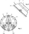
- a top plan view is shown of a mirror adjustment unit 8 according to the invention
- Fig. 3 a schematic side view is shown.
- the mirror support 9 is here represented as a ring-shaped element, but that the invention is not limited thereto.
- a support plate can be mounted on which the mirror element is mountable.
- such a construction of a mirror adjustment unit 8 whereby the mirror support 9 is rotatable relative to the base frame 11 via an adjusting mechanism 14a, 14b, is known, as described, for instance, in EP-A-1347890 .
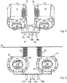
- the adjusting mechanism 14a, 14b is provided with a first electrically energizable driving device, in this case a first motor 15 for rotating the mirror support 9 relative to the base frame 11 with respect to a first axis, and with a second electrically energizable driving device, in this case also a motor 16 for rotating the mirror support 9 relative to the base frame 11 with respect to a second axis, the second axis being at least approximately perpendicular to the first axis.
- a first electrically energizable driving device in this case a first motor 15 for rotating the mirror support 9 relative to the base frame 11 with respect to a first axis
- a second electrically energizable driving device in this case also a motor 16 for rotating the mirror support 9 relative to the base frame 11 with respect to a second axis, the second axis being at least approximately perpendicular to the first axis.
- the first motor 15 is provided with a first electrical connector 17, arranged on the base frame 11, for electrical connection of the first motor 15 with the onboard network 4. Also provided is a second electrical connector 18, arranged on the base frame 11, for electrical connection of the second motor 16 with the onboard network 4.
- the first and second electrical connectors 17, 18 jointly form the exterior mirror connector 7.
- the first and second electrical connectors 17, 18 each include two separate electrical connecting elements or supply poles 17a, 17b; 18a, 18b.
- the first and second electrical connectors each include one separate electrical connecting element and one common connecting element.
- the starting point will be the embodiment with two supply poles per electrical connector.
- the electrically energizable view assist device is a heating device 19, also called heater pad, arranged on the mirror element. It will be clear to those skilled in the art that the invention also applies to other view assist devices which, for instance, may also be integrated in the mirror support 9 or the crosspiece 13.
- the mirror support, or the crosspiece forms an intermediate connector which can further, in a manner know per se, be electrically connected with the heater pad, for instance with the aid of a plug connection.
- a separate intermediate connector for instance integrated in the above-mentioned support plate, can be used, which intermediate connector is connected on one side, internally, with the first and second electrical connector 17, 18 and on the other side with the heater pad 19.
- Such a heater pad 19 is shown in Fig. 5 in front view and in Fig. 7 in top plan view and includes contact surfaces 20, 21 for enabling electrical connection with the first and second electrical connectors 17, 18.
- the mirror adjustment unit 8 further comprises a third electrical connector for the electrical connection of the heater pad with the onboard network 4, which third electrical connector is placed between the first and second electrical connectors 17, 18 and the heater pad 19 and is electrically connected with the first and second electrical connectors 17, 18.
- this third electrical connector is formed by spring elements implemented as helical springs 22, 23.
- the helical spring 22, in any case in use, is in electrical contact with a first electrically conductive motor casing 24 of the first motor 15, which motor casing is electrically connected with the supply pole 17b.
- the helical spring 23, in any case in use, is in electrical contact with a second electrically conductive motor casing 25 of the second motor 16, which motor casing 25 is electrically connected with the supply pole 18b.
- the third electrical connector hence comprises both the helical springs 22, 23 and the electrically conductive motor casings 24, 25, whereby the helical springs 22, 23, which, as represented in Fig. 6 , stick out of openings 26, 27 in the crosspiece 13, provide - after mounting of the mirror element - for a correct electrical connection with the contact surfaces of the heater pad.
- the third electrical connector can comprise a flexible current conductor, preferably implemented as flex-foil, or even relatively rigid electrical connecting wires.
- FIGs. 8 and 9 two examples of electrical circuits for the supply of the heater pad 19 are represented, Fig. 9 showing a circuit diagram whereby in one switch setting only the adjusting function of the adjusting mechanism can be activated and in the other switch setting the heater pad can be activated.
- a switching device can be integrated in a simple manner in the distribution branch 5 with control chip so that the driver of the vehicle, at will, can adjust the mirror element or can activate the heater pad.
- the exterior mirror 1 comprises at least two separate electrically energizable view assist devices, for instance a heater pad and a dimming device
- the exterior mirror 1 may be so constructed that, in use, with an electrical connection with first (+/-) or (-/+) polarity exclusively one of the view assist devices is activated, while, with an opposite (-/+) or (+/-) polarity the other of the view assist devices is activated or both view assist devices are activated.
Landscapes
- Engineering & Computer Science (AREA)
- Mechanical Engineering (AREA)
- Multimedia (AREA)
- Rear-View Mirror Devices That Are Mounted On The Exterior Of The Vehicle (AREA)
- Physics & Mathematics (AREA)
- General Engineering & Computer Science (AREA)
- General Physics & Mathematics (AREA)
- Optics & Photonics (AREA)
- Power Engineering (AREA)
Description
- This invention generally relates to a mirror adjustment unit for an exterior mirror of a motor vehicle, comprising a base frame which can be fixedly connected with a motor vehicle, and a mirror support for supporting a mirror element, which mirror support is connected rotatably relative to the base frame via an adjusting mechanism, and wherein there is provided an electrical connection between the base frame and the mirror support.
- Such a mirror adjustment unit is for instance known from Dutch patent
NL-C-1019524 NL-C-1019524 - Further, there is a trend to realize more and more electrical functions for the purpose of the use of the mirror. Consequently, because of the extra wire outputs or connecting wires from the base frame to the onboard network of a vehicle that are needed for each electrical function, it is difficult in practice to provide for a sufficiently flexible electrical connection. In addition, it is time consuming not only to arrange a bundled electrical connection between the vehicle and the base frame but also to provide the electrical connections for each electrical function between the base frame and the mirror support, which may regularly give rise to connecting errors. Also, it appears that errors can be made in placing or replacing mirror elements which contain view assist devices. For the purpose of the supply of these devices, the mirror elements include upstanding pins which make the mirror elements with view assist devices high and fragile and, in particular, make such elements difficult to stack.
- This is a problem in particular when it is taken into account that the mirror support is often supplied as a subassembly, the mirror support being provided with a mirror element and a number of electrical components for fulfilling utility functions of the mirror, such as a heating element, electrochrome glass or ultrasonic motor. Further, the subassembly mentioned is often supplied by a different supplier than the supplier of the other parts of the mirror adjustment unit, which likewise constitute a subassembly. Often, the two subassemblies of the mirror adjustment unit then have to be electrically connected with each other in a reliable manner in large numbers by a third party. As the two subassemblies of the mirror adjustment unit are each made up of a large number of components, this can entail an accumulation of dimensional tolerances, which makes assembly of the mirror adjustment unit time-consuming and hence costly.
- The object of the invention is to provide a mirror adjustment unit where, while preserving the advantages, the disadvantages mentioned can be counteracted. In particular, the invention contemplates a mirror adjustment unit whereby the electrical connection between a view assist device, in particular a view assist device arranged on the mirror element, can be accomplished in a reliable and efficient manner with a relatively small number of electrical connecting wires from an onboard network of a vehicle to the mirror adjustment unit. Document
DE 2627918 discloses a mirror adjustment unit according to the preamble of claim 1. - To this end, the invention provides a mirror adjustment unit for an exterior mirror of a motor vehicle according to claim 1.
- By making use, according to the invention, of the already present electrical connectors for the electrically energizable driving devices, an electrical connection belonging to the mirror adjustment unit, in particular an internal one, will suffice for the supply of a view assist device, without necessitating additional electrical connections from the mirror adjustment unit to the onboard network of the vehicle.
- In an embodiment of a mirror adjustment unit according to the invention, the third electrical connector comprises spring elements. Such spring elements are particularly suitable for maintaining an electrical connection between a view assist device and a base frame that are rotatable relative to each other during mirror adjustment. It is then advantageous when on the view assist device two contact surfaces are provided against which the spring elements abut. Preferably, the spring elements are implemented as helical springs which provide sufficient compressive stress for providing electrical contact at all times. In an embodiment in which the view assist device and the base frame are not rotatable relative to each other during mirror adjustment, the third electrical connector can contain non-spring, that is, rigid elements.
- In an alternative embodiment of a mirror adjustment unit, the third electrical connector comprises a flexible current conductor, in other words, a current conductor which is bendable in a direction transversely to its extension, but does not provide any bias in a direction of its extension. It is then particularly advantageous when the flexible current conductor is implemented as a so-called flex-foil.
- In a further embodiment of a mirror adjustment unit according to the invention, in which the electrically energizable view assist device is arranged on a mirror element to be supported by the mirror support, a correct and reliable electrical connection can be realized when the third electrical connector comprises an intermediate connector, arranged on the mirror support, for electrical connection of the electrically energizable view assist device with the onboard network via the intermediate connector, which intermediate connector is electrically connected with the first and second electrical connectors and is electrically connectable with the electrically energizable view assist device arranged on the mirror element.
- According to the invention, a compact mirror adjustment unit can be obtained with a reliable electrical connection to the view assist devices when the first electrically energizable driving device comprises a first motor with a first electrically conductive motor casing and/or the second electrically energizable driving device comprises a second motor with a second electrically conductive motor casing, wherein the first and/or second motor casing is electrically connected with the first and second electrical connector, respectively, and wherein the third electrical connector comprises the first and/or second motor casing. By connecting one of the two supply poles of the first and/or second electrical connector with the (metal) motor casing, not only disturbing radiation emission is reduced or obviated, but also, because of the nature of the make-up of the adjusting mechanism, the motor casings, after assembly of the mirror element, extend to a point just below the mirror element, so that a compact construction can be obtained as well.
- In an embodiment of a mirror adjustment unit according to the invention, the first and second electrical connectors each include two separate electrical connecting elements, which results in four connecting elements (or supply poles) overall. In an alternative variant of a mirror adjustment unit according to the invention, the first and second electrical connectors each include one separate electrical connecting element and one common connecting element, which results in three connecting elements, with the common connecting element forming the ground. Both types (i.e., three or four connecting elements) are conventionally used in the vehicle technique and require exclusively standard connectors, so that a mirror adjustment unit according to the invention, where connectors are concerned, does not require any modifications. The first and second electrical connectors are preferably included in one common connector housing, such as an exterior mirror connector, so that there is one common connector output which is connectable with a single cable bundle for supplying or energizing the first and second driving devices and the one or more view assist devices.
- What is thereby achieved is that the electrical connection can be easily made of multiple design, while preserving the flexibility of the electrical connection.
- The invention also relates to an exterior mirror for a motor vehicle, comprising a mirror adjustment unit according to any one of the mirror adjustment unit claims and a mirror element arranged on the mirror support.
- In an advantageous embodiment of an exterior mirror according to the invention in which it is possible to supply two different view assist devices with just one third electrical connector, for instance one pair of compression springs, the exterior mirror comprises at least two separate electrically energizable view assist devices, wherein the at least two separate electrically energizable view assist devices are arranged on the adjusting mechanism or are arranged on the mirror element or one electrically energizable view assist device is arranged on the adjusting mechanism and the other view assist device is arranged on the mirror element, wherein the exterior mirror is so constructed that in use with an electrical connection with a first polarity exclusively one of the view assist devices is activated while with an opposite polarity the other of the view assist devices is activated or both view assist devices are activated.
- The invention will be further elucidated on the basis of a number of exemplary embodiments which are represented in a drawing. In the drawing:
-
Fig. 1 shows a schematic view of an exterior mirror mounted on a door of a vehicle; -
Fig. 2 shows a schematic top plan view of a mirror adjustment unit for an exterior mirror shown inFig. 1 ; -
Fig. 3 shows a schematic side view of the mirror adjustment unit ofFig. 2 ; -
Fig. 4 shows a schematic top plan view in perspective of motors and electrical connectors of the mirror adjustment unit ofFigs. 2 and 3 ; -
Fig. 5 shows a schematic front view ofFig. 4 with heater pad; -
Fig. 6 shows a schematic view in perspective of a part of a crosspiece with, sticking through it, helical springs of the mirror adjustment unit ofFigs. 2 to 5 ; -
Fig. 7 shows a schematic top plan view of a heater pad arranged on the mirror adjustment unit; and -
Figs. 8 and 9 show examples of electrical circuits to be used in the mirror adjustment unit according to the invention. - The figures are only schematic representations of preferred embodiments of the invention. In the figures, the same or corresponding parts are indicated with the same reference numerals.
-
Fig. 1 shows a schematic representation of an exterior mirror 1 of amotor vehicle 2. The exterior mirror 1 in this exemplary embodiment is mounted on the outside 2A of adoor 3 of themotor vehicle 2. In thedoor 3 of themotor vehicle 2 runs a part of the electrical onboard network 4 of themotor vehicle 2, which onboard network 4 advantageously comprises adistribution branch 5 with a control chip for electrically supplying electrically controllable means of the exterior mirror 1 via an exterior mirror feeder cable 6. The exterior mirror feeder cable 6 is connected with anexterior mirror connector 7 of a mirror adjustment unit 8 which comprises a mirror support 9 for supporting amirror element 10. The mirror adjustment unit 8 further comprises abase frame 11 which can be connected with themotor vehicle 2, in particular by attaching it to asupport construction 12 which is pivotably mounted on thedoor 3 of themotor vehicle 2 in a conventional manner. - In
Fig. 2 , schematically, a top plan view is shown of a mirror adjustment unit 8 according to the invention, while inFig. 3 a schematic side view is shown. It is noted that the mirror support 9 is here represented as a ring-shaped element, but that the invention is not limited thereto. In particular, in embodiments not shown, it is possible that on the mirror support 9 and the crosspiece 13 a support plate can be mounted on which the mirror element is mountable. In general, such a construction of a mirror adjustment unit 8 whereby the mirror support 9 is rotatable relative to thebase frame 11 via anadjusting mechanism EP-A-1347890 . - As is represented in
Figs. 4 and 5 , theadjusting mechanism first motor 15 for rotating the mirror support 9 relative to thebase frame 11 with respect to a first axis, and with a second electrically energizable driving device, in this case also amotor 16 for rotating the mirror support 9 relative to thebase frame 11 with respect to a second axis, the second axis being at least approximately perpendicular to the first axis. - The
first motor 15 is provided with a firstelectrical connector 17, arranged on thebase frame 11, for electrical connection of thefirst motor 15 with the onboard network 4. Also provided is a secondelectrical connector 18, arranged on thebase frame 11, for electrical connection of thesecond motor 16 with the onboard network 4. The first and secondelectrical connectors exterior mirror connector 7. - In the embodiment as represented in
Figs. 4 and 5 , the first and secondelectrical connectors supply poles heating device 19, also called heater pad, arranged on the mirror element. It will be clear to those skilled in the art that the invention also applies to other view assist devices which, for instance, may also be integrated in the mirror support 9 or thecrosspiece 13. In that case, the mirror support, or the crosspiece, forms an intermediate connector which can further, in a manner know per se, be electrically connected with the heater pad, for instance with the aid of a plug connection. In addition, a separate intermediate connector, for instance integrated in the above-mentioned support plate, can be used, which intermediate connector is connected on one side, internally, with the first and secondelectrical connector heater pad 19. - Such a
heater pad 19 is shown inFig. 5 in front view and inFig. 7 in top plan view and includes contact surfaces 20, 21 for enabling electrical connection with the first and secondelectrical connectors - This last mentioned electrical connection is realized according to the invention in that the mirror adjustment unit 8 further comprises a third electrical connector for the electrical connection of the heater pad with the onboard network 4, which third electrical connector is placed between the first and second
electrical connectors heater pad 19 and is electrically connected with the first and secondelectrical connectors helical springs helical spring 22, in any case in use, is in electrical contact with a first electricallyconductive motor casing 24 of thefirst motor 15, which motor casing is electrically connected with thesupply pole 17b. Analogously, thehelical spring 23, in any case in use, is in electrical contact with a second electricallyconductive motor casing 25 of thesecond motor 16, which motorcasing 25 is electrically connected with thesupply pole 18b. The third electrical connector hence comprises both thehelical springs conductive motor casings helical springs Fig. 6 , stick out ofopenings crosspiece 13, provide - after mounting of the mirror element - for a correct electrical connection with the contact surfaces of the heater pad. - In alternative embodiments and/or for the electrical supply of other view assist devices, the third electrical connector can comprise a flexible current conductor, preferably implemented as flex-foil, or even relatively rigid electrical connecting wires.
- In
Figs. 8 and 9 two examples of electrical circuits for the supply of theheater pad 19 are represented,Fig. 9 showing a circuit diagram whereby in one switch setting only the adjusting function of the adjusting mechanism can be activated and in the other switch setting the heater pad can be activated. Such a switching device can be integrated in a simple manner in thedistribution branch 5 with control chip so that the driver of the vehicle, at will, can adjust the mirror element or can activate the heater pad. - If the exterior mirror 1 comprises at least two separate electrically energizable view assist devices, for instance a heater pad and a dimming device, then the exterior mirror 1 may be so constructed that, in use, with an electrical connection with first (+/-) or (-/+) polarity exclusively one of the view assist devices is activated, while, with an opposite (-/+) or (+/-) polarity the other of the view assist devices is activated or both view assist devices are activated.
Claims (10)
- A mirror adjustment unit for an exterior mirror (1) of a motor vehicle (2), comprising a base frame (11) which is connectable with a motor vehicle (2) and a mirror support (9) for supporting a mirror element (10), which mirror support is connected rotatably relative to the base frame (11) via an adjusting mechanism (14a, 14b), wherein the adjusting mechanism (14a, 14b) is provided with a first electrically energizable driving device (15) for rotating the mirror support (9) relative to the base frame (11) with respect to a first axis, and with a second electrically energizable driving device (16) for rotating the mirror support (9) relative to the base frame (11) with respect to a second axis, wherein the second axis is at least approximately perpendicular to the first axis, wherein the first driving device (15) is provided with a first electrical connector (17) arranged on the base frame (11) for electrical connection of the first driving device (15) with an onboard network (4) of a motor vehicle (2) to which the base frame (11) is connectable, and wherein the second driving device (16) is provided with a second electrical connector (18) arranged on the base frame (11) for electrical connection of the second driving device (16) with the onboard network (4), wherein the mirror adjustment unit (8) further comprises a third electrical connector for electrical connection of an electrically energizable view assist device (19) with the onboard network (4), which electrically energizable view assist device is arranged on the adjusting mechanism (14a, 14b) or is arranged on the mirror element (10) to be supported by the mirror support (9), wherein the third electrical connector is placed between, and electrically connected with, on one side, the first and second electrical connectors (17, 18) and, on the other side, the electrically energizable view assist device (19),
characterized in that
the first electrically energizable driving device (15) comprises a first motor with a first electrically conductive motor casing (24) and/or the second electrically energizable driving device (16) comprises a second motor with a second electrically conductive motor casing (26), wherein the first and/or second motor casing (25, 26) is electrically connected with the first and second electrical connector (17, 18), respectively, and wherein the third electrical connector comprises the first and/or second motor casing (25, 26). - A mirror adjustment unit according to claim 1, wherein the third electrical connector comprises spring elements (22, 23).
- A mirror adjustment unit according to claim 2, wherein the spring elements are implemented as helical springs (22, 23).
- A mirror adjustment unit according to claim 1, wherein the third electrical connector comprises a flexible current conductor.
- A mirror adjustment unit according to claim 4, wherein the flexible current conductor is implemented as flex-foil.
- A mirror adjustment unit according to any one of the preceding claims, wherein the electrically energizable view assist device (19) is arranged on a mirror element (10) to be supported by the mirror support (9), and wherein the third electrical connector comprises an intermediate connector arranged on the mirror support for electrical connection of the electrically energizable view assist device (19) with the onboard network (4) via the intermediate connector, which intermediate connector is electrically connected with the first and second electrical connectors (17, 18) and is electrically connectable with the electrically energizable view assist device (19) arranged on the mirror element (10).
- A mirror adjustment unit according to any one of the preceding claims, wherein the first and second electrical connectors (17, 18) each contain two separate electrical connecting elements (17a, 17b; 18a, 18b).
- A mirror adjustment unit according to any one of the preceding claims, wherein the first and second electrical connectors (17, 18) each contain one separate electrical connecting element and one common connecting element.
- An exterior mirror for a motor vehicle comprising a mirror adjustment unit (8) according to any one of the preceding claims and a mirror element (10) arranged on the mirror support (9).
- An exterior mirror according to claim 9, wherein the exterior mirror (1) comprises at least two separate electrically energizable view assist devices, wherein the at least two separate electrically energizable view assist devices are arranged on the adjusting mechanism (8) or are arranged on the mirror element (10) or one electrically energizable view assist device (19) is arranged on the adjusting mechanism (8) and the other view assist device is arranged on the mirror element (10), wherein the exterior mirror (1) is so constructed that, in use, with an electrical connection with a first polarity exclusively one of the view assist devices is activated, while with an opposite polarity the other of the view assist devices is activated or both view assist devices are activated.
Applications Claiming Priority (2)
| Application Number | Priority Date | Filing Date | Title |
|---|---|---|---|
| NL2010811A NL2010811C2 (en) | 2013-05-16 | 2013-05-16 | MIRROR-ADJUSTMENT UNIT AND EXTERIOR MIRROR FOR A MOTOR VEHICLE INCLUDING SUCH A MIRROR-ADJUSTMENT UNIT. |
| PCT/NL2014/050313 WO2014185785A1 (en) | 2013-05-16 | 2014-05-16 | Mirror adjustment unit and exterior mirror for a motor vehicle comprising such a mirror adjustment unit |
Publications (2)
| Publication Number | Publication Date |
|---|---|
| EP2996902A1 EP2996902A1 (en) | 2016-03-23 |
| EP2996902B1 true EP2996902B1 (en) | 2017-03-15 |
Family
ID=48790550
Family Applications (1)
| Application Number | Title | Priority Date | Filing Date |
|---|---|---|---|
| EP14729981.2A Active EP2996902B1 (en) | 2013-05-16 | 2014-05-16 | Mirror adjustment unit and exterior mirror for a motor vehicle comprising such a mirror adjustment unit |
Country Status (7)
| Country | Link |
|---|---|
| US (1) | US20160121796A1 (en) |
| EP (1) | EP2996902B1 (en) |
| JP (1) | JP2016521229A (en) |
| KR (1) | KR102191222B1 (en) |
| CN (1) | CN105228857B (en) |
| NL (1) | NL2010811C2 (en) |
| WO (1) | WO2014185785A1 (en) |
Families Citing this family (1)
| Publication number | Priority date | Publication date | Assignee | Title |
|---|---|---|---|---|
| CN107757493A (en) * | 2017-10-30 | 2018-03-06 | 杜荷昌 | It is a kind of with rearview mirror is detachable and the electric automobile of seat regulatory function |
Family Cites Families (16)
| Publication number | Priority date | Publication date | Assignee | Title |
|---|---|---|---|---|
| DE2627918C3 (en) * | 1976-06-22 | 1979-02-08 | Bayerische Motoren Werke Ag, 8000 Muenchen | Circuit arrangement for electrical consumers in a motor vehicle |
| DE3812993A1 (en) * | 1988-04-19 | 1989-11-02 | Bernhard Mittelhaeuser | EXTERNAL REAR VIEW MIRROR FOR MOTOR VEHICLES |
| DE4029890C2 (en) * | 1990-09-21 | 1999-03-11 | Mekra Lang Gmbh & Co Kg | Review device for motor vehicles |
| US5659423A (en) * | 1994-09-30 | 1997-08-19 | Donnelly Corporation | Modular variable reflectance mirror assembly |
| JP3138600B2 (en) * | 1994-10-12 | 2001-02-26 | 株式会社石▼崎▲本店 | Mirror drive |
| NL1016676C2 (en) | 2000-11-22 | 2002-05-23 | Iku Holding Montfoort Bv | Movement mechanism. |
| US6650457B2 (en) * | 2001-05-21 | 2003-11-18 | Gentex Corporation | Rearview mirror constructed for efficient assembly |
| NL1019524C2 (en) | 2001-12-07 | 2003-06-11 | Iku Holding Montfoort Bv | Mirror adjustment mechanism with electrical connection. |
| ATE482850T1 (en) * | 2007-07-19 | 2010-10-15 | Smr Patents Sarl | DEVICE FOR ADJUSTING THE ALIGNMENT OF A MIRROR OF A MOTOR VEHICLE |
| US8783883B2 (en) * | 2010-08-30 | 2014-07-22 | Honda Motor Co., Ltd. | Method for controlling power to a motor in a vehicle door mirror |
| JP5710227B2 (en) * | 2010-11-30 | 2015-04-30 | 株式会社東海理化電機製作所 | Mirror device for vehicle |
| US9067541B2 (en) * | 2011-10-31 | 2015-06-30 | Magna Mirrors Of America, Inc. | Exterior mirror assembly with actuator |
| US9242606B2 (en) * | 2012-11-09 | 2016-01-26 | Magna Mirrors Of America, Inc. | Exterior mirror assembly with actuator |
| US10076999B2 (en) * | 2013-05-03 | 2018-09-18 | Mci (Mirror Controls International) Netherlands B.V. | Movement mechanism and wing mirror for a vehicle provided with such a movement mechanism |
| US9776569B2 (en) * | 2015-01-30 | 2017-10-03 | Magna Mirrors Of America, Inc. | Exterior mirror with heater pad |
| KR101652889B1 (en) * | 2015-03-13 | 2016-09-01 | 주식회사 호영자동차부품 | Apparatus for adjusting outside rear view mirror for vehicle |
-
2013
- 2013-05-16 NL NL2010811A patent/NL2010811C2/en not_active IP Right Cessation
-
2014
- 2014-05-16 JP JP2016513896A patent/JP2016521229A/en active Pending
- 2014-05-16 KR KR1020157032868A patent/KR102191222B1/en active Active
- 2014-05-16 WO PCT/NL2014/050313 patent/WO2014185785A1/en not_active Ceased
- 2014-05-16 CN CN201480028430.2A patent/CN105228857B/en active Active
- 2014-05-16 US US14/888,065 patent/US20160121796A1/en not_active Abandoned
- 2014-05-16 EP EP14729981.2A patent/EP2996902B1/en active Active
Non-Patent Citations (1)
| Title |
|---|
| None * |
Also Published As
| Publication number | Publication date |
|---|---|
| CN105228857B (en) | 2018-01-26 |
| NL2010811C2 (en) | 2014-11-24 |
| JP2016521229A (en) | 2016-07-21 |
| EP2996902A1 (en) | 2016-03-23 |
| KR20160010456A (en) | 2016-01-27 |
| CN105228857A (en) | 2016-01-06 |
| US20160121796A1 (en) | 2016-05-05 |
| WO2014185785A1 (en) | 2014-11-20 |
| KR102191222B1 (en) | 2020-12-16 |
Similar Documents
| Publication | Publication Date | Title |
|---|---|---|
| US6481878B2 (en) | Exterior rearview mirror assembly | |
| US20110317298A1 (en) | Mirror adjustment unit provided with an electric accessory | |
| US6312135B1 (en) | Electric external rear view mirror | |
| US7244912B1 (en) | Vehicular mirror with heater circuit module | |
| JP2015227089A (en) | Vehicular harness structure | |
| CN101600606A (en) | electric drive | |
| US20130003264A1 (en) | Electric junction box | |
| US12162533B1 (en) | Control assembly for zero turn vehicle | |
| US9368920B2 (en) | Plug-cable unit for a removable coding plug, coding plug and method for configuring a functional unit with a coding plug | |
| JP2019102304A (en) | Circuit body for vehicle | |
| US20160121796A1 (en) | Mirror Adjustment Unit and Exterior Mirror for a Motor Vehicle Comprising Such a Mirror Adjustment Unit | |
| JP5722727B2 (en) | Remote control mirror drive device and remote control mirror assembly method | |
| CN113169472B (en) | Electronic control device and electric power steering device | |
| US7541704B2 (en) | Electric machine including a brush-holder support having flex foil, as well as a method for producing a brush-holder support | |
| JP2010049815A (en) | On-vehicle electric component control unit and control component | |
| CN107089196B (en) | Adjustment system for a rear-view element of a vehicle rear-view device | |
| WO2000027670A1 (en) | Electrically controlled mirror for a motor vehicle | |
| JP5156965B2 (en) | Actuators for automotive components | |
| JP5250105B2 (en) | Electrical machine with electrical terminals, connector plugs and plug-in connectors | |
| JP2008503862A (en) | Device for connecting basic electrical components and auxiliary electrical components, in particular to an automobile track network, and a method for manufacturing such a connection device | |
| EP4499482B1 (en) | Vehicle steering wheel comprising a plurality of different electrical devices | |
| WO2003047909A1 (en) | Mirror adjustment mechanism with electrical connection | |
| US20020041454A1 (en) | Motor vehicle rearview mirror | |
| CN109661329B (en) | Vehicle circuit body | |
| JP6544450B2 (en) | Wiper motor |
Legal Events
| Date | Code | Title | Description |
|---|---|---|---|
| PUAI | Public reference made under article 153(3) epc to a published international application that has entered the european phase |
Free format text: ORIGINAL CODE: 0009012 |
|
| 17P | Request for examination filed |
Effective date: 20151130 |
|
| AK | Designated contracting states |
Kind code of ref document: A1 Designated state(s): AL AT BE BG CH CY CZ DE DK EE ES FI FR GB GR HR HU IE IS IT LI LT LU LV MC MK MT NL NO PL PT RO RS SE SI SK SM TR |
|
| AX | Request for extension of the european patent |
Extension state: BA ME |
|
| DAX | Request for extension of the european patent (deleted) | ||
| GRAP | Despatch of communication of intention to grant a patent |
Free format text: ORIGINAL CODE: EPIDOSNIGR1 |
|
| INTG | Intention to grant announced |
Effective date: 20161123 |
|
| GRAS | Grant fee paid |
Free format text: ORIGINAL CODE: EPIDOSNIGR3 |
|
| GRAA | (expected) grant |
Free format text: ORIGINAL CODE: 0009210 |
|
| AK | Designated contracting states |
Kind code of ref document: B1 Designated state(s): AL AT BE BG CH CY CZ DE DK EE ES FI FR GB GR HR HU IE IS IT LI LT LU LV MC MK MT NL NO PL PT RO RS SE SI SK SM TR |
|
| REG | Reference to a national code |
Ref country code: CH Ref legal event code: EP Ref country code: GB Ref legal event code: FG4D |
|
| REG | Reference to a national code |
Ref country code: IE Ref legal event code: FG4D |
|
| REG | Reference to a national code |
Ref country code: AT Ref legal event code: REF Ref document number: 875174 Country of ref document: AT Kind code of ref document: T Effective date: 20170415 |
|
| REG | Reference to a national code |
Ref country code: DE Ref legal event code: R096 Ref document number: 602014007657 Country of ref document: DE |
|
| REG | Reference to a national code |
Ref country code: FR Ref legal event code: PLFP Year of fee payment: 4 |
|
| REG | Reference to a national code |
Ref country code: NL Ref legal event code: MP Effective date: 20170315 |
|
| REG | Reference to a national code |
Ref country code: LT Ref legal event code: MG4D |
|
| PG25 | Lapsed in a contracting state [announced via postgrant information from national office to epo] |
Ref country code: LT Free format text: LAPSE BECAUSE OF FAILURE TO SUBMIT A TRANSLATION OF THE DESCRIPTION OR TO PAY THE FEE WITHIN THE PRESCRIBED TIME-LIMIT Effective date: 20170315 Ref country code: HR Free format text: LAPSE BECAUSE OF FAILURE TO SUBMIT A TRANSLATION OF THE DESCRIPTION OR TO PAY THE FEE WITHIN THE PRESCRIBED TIME-LIMIT Effective date: 20170315 Ref country code: FI Free format text: LAPSE BECAUSE OF FAILURE TO SUBMIT A TRANSLATION OF THE DESCRIPTION OR TO PAY THE FEE WITHIN THE PRESCRIBED TIME-LIMIT Effective date: 20170315 Ref country code: NO Free format text: LAPSE BECAUSE OF FAILURE TO SUBMIT A TRANSLATION OF THE DESCRIPTION OR TO PAY THE FEE WITHIN THE PRESCRIBED TIME-LIMIT Effective date: 20170615 Ref country code: GR Free format text: LAPSE BECAUSE OF FAILURE TO SUBMIT A TRANSLATION OF THE DESCRIPTION OR TO PAY THE FEE WITHIN THE PRESCRIBED TIME-LIMIT Effective date: 20170616 |
|
| REG | Reference to a national code |
Ref country code: AT Ref legal event code: MK05 Ref document number: 875174 Country of ref document: AT Kind code of ref document: T Effective date: 20170315 |
|
| PG25 | Lapsed in a contracting state [announced via postgrant information from national office to epo] |
Ref country code: SE Free format text: LAPSE BECAUSE OF FAILURE TO SUBMIT A TRANSLATION OF THE DESCRIPTION OR TO PAY THE FEE WITHIN THE PRESCRIBED TIME-LIMIT Effective date: 20170315 Ref country code: LV Free format text: LAPSE BECAUSE OF FAILURE TO SUBMIT A TRANSLATION OF THE DESCRIPTION OR TO PAY THE FEE WITHIN THE PRESCRIBED TIME-LIMIT Effective date: 20170315 Ref country code: RS Free format text: LAPSE BECAUSE OF FAILURE TO SUBMIT A TRANSLATION OF THE DESCRIPTION OR TO PAY THE FEE WITHIN THE PRESCRIBED TIME-LIMIT Effective date: 20170315 Ref country code: BG Free format text: LAPSE BECAUSE OF FAILURE TO SUBMIT A TRANSLATION OF THE DESCRIPTION OR TO PAY THE FEE WITHIN THE PRESCRIBED TIME-LIMIT Effective date: 20170615 Ref country code: LU Free format text: LAPSE BECAUSE OF NON-PAYMENT OF DUE FEES Effective date: 20170531 |
|
| PG25 | Lapsed in a contracting state [announced via postgrant information from national office to epo] |
Ref country code: NL Free format text: LAPSE BECAUSE OF FAILURE TO SUBMIT A TRANSLATION OF THE DESCRIPTION OR TO PAY THE FEE WITHIN THE PRESCRIBED TIME-LIMIT Effective date: 20170315 |
|
| PG25 | Lapsed in a contracting state [announced via postgrant information from national office to epo] |
Ref country code: SK Free format text: LAPSE BECAUSE OF FAILURE TO SUBMIT A TRANSLATION OF THE DESCRIPTION OR TO PAY THE FEE WITHIN THE PRESCRIBED TIME-LIMIT Effective date: 20170315 Ref country code: IT Free format text: LAPSE BECAUSE OF FAILURE TO SUBMIT A TRANSLATION OF THE DESCRIPTION OR TO PAY THE FEE WITHIN THE PRESCRIBED TIME-LIMIT Effective date: 20170315 Ref country code: ES Free format text: LAPSE BECAUSE OF FAILURE TO SUBMIT A TRANSLATION OF THE DESCRIPTION OR TO PAY THE FEE WITHIN THE PRESCRIBED TIME-LIMIT Effective date: 20170315 Ref country code: CZ Free format text: LAPSE BECAUSE OF FAILURE TO SUBMIT A TRANSLATION OF THE DESCRIPTION OR TO PAY THE FEE WITHIN THE PRESCRIBED TIME-LIMIT Effective date: 20170315 Ref country code: AT Free format text: LAPSE BECAUSE OF FAILURE TO SUBMIT A TRANSLATION OF THE DESCRIPTION OR TO PAY THE FEE WITHIN THE PRESCRIBED TIME-LIMIT Effective date: 20170315 Ref country code: RO Free format text: LAPSE BECAUSE OF FAILURE TO SUBMIT A TRANSLATION OF THE DESCRIPTION OR TO PAY THE FEE WITHIN THE PRESCRIBED TIME-LIMIT Effective date: 20170315 Ref country code: EE Free format text: LAPSE BECAUSE OF FAILURE TO SUBMIT A TRANSLATION OF THE DESCRIPTION OR TO PAY THE FEE WITHIN THE PRESCRIBED TIME-LIMIT Effective date: 20170315 |
|
| PG25 | Lapsed in a contracting state [announced via postgrant information from national office to epo] |
Ref country code: PT Free format text: LAPSE BECAUSE OF FAILURE TO SUBMIT A TRANSLATION OF THE DESCRIPTION OR TO PAY THE FEE WITHIN THE PRESCRIBED TIME-LIMIT Effective date: 20170717 Ref country code: PL Free format text: LAPSE BECAUSE OF FAILURE TO SUBMIT A TRANSLATION OF THE DESCRIPTION OR TO PAY THE FEE WITHIN THE PRESCRIBED TIME-LIMIT Effective date: 20170315 Ref country code: IS Free format text: LAPSE BECAUSE OF FAILURE TO SUBMIT A TRANSLATION OF THE DESCRIPTION OR TO PAY THE FEE WITHIN THE PRESCRIBED TIME-LIMIT Effective date: 20170715 Ref country code: SM Free format text: LAPSE BECAUSE OF FAILURE TO SUBMIT A TRANSLATION OF THE DESCRIPTION OR TO PAY THE FEE WITHIN THE PRESCRIBED TIME-LIMIT Effective date: 20170315 |
|
| REG | Reference to a national code |
Ref country code: DE Ref legal event code: R097 Ref document number: 602014007657 Country of ref document: DE |
|
| REG | Reference to a national code |
Ref country code: CH Ref legal event code: PL |
|
| PLBE | No opposition filed within time limit |
Free format text: ORIGINAL CODE: 0009261 |
|
| STAA | Information on the status of an ep patent application or granted ep patent |
Free format text: STATUS: NO OPPOSITION FILED WITHIN TIME LIMIT |
|
| PG25 | Lapsed in a contracting state [announced via postgrant information from national office to epo] |
Ref country code: MC Free format text: LAPSE BECAUSE OF FAILURE TO SUBMIT A TRANSLATION OF THE DESCRIPTION OR TO PAY THE FEE WITHIN THE PRESCRIBED TIME-LIMIT Effective date: 20170315 Ref country code: DK Free format text: LAPSE BECAUSE OF FAILURE TO SUBMIT A TRANSLATION OF THE DESCRIPTION OR TO PAY THE FEE WITHIN THE PRESCRIBED TIME-LIMIT Effective date: 20170315 |
|
| 26N | No opposition filed |
Effective date: 20171218 |
|
| REG | Reference to a national code |
Ref country code: IE Ref legal event code: MM4A |
|
| PG25 | Lapsed in a contracting state [announced via postgrant information from national office to epo] |
Ref country code: CH Free format text: LAPSE BECAUSE OF NON-PAYMENT OF DUE FEES Effective date: 20170531 Ref country code: LI Free format text: LAPSE BECAUSE OF NON-PAYMENT OF DUE FEES Effective date: 20170531 Ref country code: SI Free format text: LAPSE BECAUSE OF FAILURE TO SUBMIT A TRANSLATION OF THE DESCRIPTION OR TO PAY THE FEE WITHIN THE PRESCRIBED TIME-LIMIT Effective date: 20170315 |
|
| PG25 | Lapsed in a contracting state [announced via postgrant information from national office to epo] |
Ref country code: LU Free format text: LAPSE BECAUSE OF NON-PAYMENT OF DUE FEES Effective date: 20170516 |
|
| REG | Reference to a national code |
Ref country code: BE Ref legal event code: MM Effective date: 20170531 |
|
| PG25 | Lapsed in a contracting state [announced via postgrant information from national office to epo] |
Ref country code: IE Free format text: LAPSE BECAUSE OF NON-PAYMENT OF DUE FEES Effective date: 20170516 |
|
| REG | Reference to a national code |
Ref country code: FR Ref legal event code: PLFP Year of fee payment: 5 |
|
| PG25 | Lapsed in a contracting state [announced via postgrant information from national office to epo] |
Ref country code: BE Free format text: LAPSE BECAUSE OF NON-PAYMENT OF DUE FEES Effective date: 20170531 |
|
| PG25 | Lapsed in a contracting state [announced via postgrant information from national office to epo] |
Ref country code: MT Free format text: LAPSE BECAUSE OF NON-PAYMENT OF DUE FEES Effective date: 20170516 |
|
| PG25 | Lapsed in a contracting state [announced via postgrant information from national office to epo] |
Ref country code: HU Free format text: LAPSE BECAUSE OF FAILURE TO SUBMIT A TRANSLATION OF THE DESCRIPTION OR TO PAY THE FEE WITHIN THE PRESCRIBED TIME-LIMIT; INVALID AB INITIO Effective date: 20140516 |
|
| PG25 | Lapsed in a contracting state [announced via postgrant information from national office to epo] |
Ref country code: CY Free format text: LAPSE BECAUSE OF FAILURE TO SUBMIT A TRANSLATION OF THE DESCRIPTION OR TO PAY THE FEE WITHIN THE PRESCRIBED TIME-LIMIT Effective date: 20170315 |
|
| PG25 | Lapsed in a contracting state [announced via postgrant information from national office to epo] |
Ref country code: MK Free format text: LAPSE BECAUSE OF FAILURE TO SUBMIT A TRANSLATION OF THE DESCRIPTION OR TO PAY THE FEE WITHIN THE PRESCRIBED TIME-LIMIT Effective date: 20170315 |
|
| PG25 | Lapsed in a contracting state [announced via postgrant information from national office to epo] |
Ref country code: TR Free format text: LAPSE BECAUSE OF FAILURE TO SUBMIT A TRANSLATION OF THE DESCRIPTION OR TO PAY THE FEE WITHIN THE PRESCRIBED TIME-LIMIT Effective date: 20170315 |
|
| PG25 | Lapsed in a contracting state [announced via postgrant information from national office to epo] |
Ref country code: AL Free format text: LAPSE BECAUSE OF FAILURE TO SUBMIT A TRANSLATION OF THE DESCRIPTION OR TO PAY THE FEE WITHIN THE PRESCRIBED TIME-LIMIT Effective date: 20170315 |
|
| P01 | Opt-out of the competence of the unified patent court (upc) registered |
Effective date: 20230516 |
|
| PGFP | Annual fee paid to national office [announced via postgrant information from national office to epo] |
Ref country code: GB Payment date: 20260324 Year of fee payment: 13 |
|
| PGFP | Annual fee paid to national office [announced via postgrant information from national office to epo] |
Ref country code: DE Payment date: 20260522 Year of fee payment: 13 |
|
| PGFP | Annual fee paid to national office [announced via postgrant information from national office to epo] |
Ref country code: FR Payment date: 20260526 Year of fee payment: 13 |