EP2996442A1 - Signal display lamp - Google Patents
Signal display lamp Download PDFInfo
- Publication number
- EP2996442A1 EP2996442A1 EP13883908.9A EP13883908A EP2996442A1 EP 2996442 A1 EP2996442 A1 EP 2996442A1 EP 13883908 A EP13883908 A EP 13883908A EP 2996442 A1 EP2996442 A1 EP 2996442A1
- Authority
- EP
- European Patent Office
- Prior art keywords
- light emission
- emission color
- light emitting
- light
- buzzer
- Prior art date
- Legal status (The legal status is an assumption and is not a legal conclusion. Google has not performed a legal analysis and makes no representation as to the accuracy of the status listed.)
- Granted
Links
Images


Classifications
-
- G—PHYSICS
- G08—SIGNALLING
- G08B—SIGNALLING SYSTEMS, e.g. PERSONAL CALLING SYSTEMS; ORDER TELEGRAPHS; ALARM SYSTEMS
- G08B5/00—Visible signalling systems, e.g. visible personal calling systems or remote indication of seats occupied
-
- H—ELECTRICITY
- H05—ELECTRIC TECHNIQUES NOT OTHERWISE PROVIDED FOR
- H05B—ELECTRIC HEATING; ELECTRIC LIGHT SOURCES NOT OTHERWISE PROVIDED FOR; CIRCUIT ARRANGEMENTS FOR ELECTRIC LIGHT SOURCES, IN GENERAL
- H05B45/00—Circuit arrangements for operating light-emitting diodes [LED]
- H05B45/20—Controlling the colour of the light
-
- H—ELECTRICITY
- H05—ELECTRIC TECHNIQUES NOT OTHERWISE PROVIDED FOR
- H05B—ELECTRIC HEATING; ELECTRIC LIGHT SOURCES NOT OTHERWISE PROVIDED FOR; CIRCUIT ARRANGEMENTS FOR ELECTRIC LIGHT SOURCES, IN GENERAL
- H05B47/00—Circuit arrangements for operating light sources in general, i.e. where the type of light source is not relevant
- H05B47/10—Controlling the light source
- H05B47/155—Coordinated control of two or more light sources
-
- F—MECHANICAL ENGINEERING; LIGHTING; HEATING; WEAPONS; BLASTING
- F21—LIGHTING
- F21W—INDEXING SCHEME ASSOCIATED WITH SUBCLASSES F21K, F21L, F21S and F21V, RELATING TO USES OR APPLICATIONS OF LIGHTING DEVICES OR SYSTEMS
- F21W2111/00—Use or application of lighting devices or systems for signalling, marking or indicating, not provided for in codes F21W2102/00 – F21W2107/00
Definitions
- the present invention relates to a signal indicator lamp including a plurality of light emitting units.
- a signal indicator lamp is arranged so that its turned-on state is controlled based on control signals supplied from a control device such as a programmable logic controller (PLC) that controls mechanical equipment such as production equipment.
- PLC programmable logic controller
- the signal indicator lamp disclosed in Patent Literature 1 includes a plurality of stacked cells, an LED substrate disposed so as to penetrate through the plurality of cells, and LEDs (light-emitting diodes) mounted to both surfaces of the LED substrate.
- the LED substrate is provided with red, green, and blue LEDs for each cell. Accordingly, each cell can assume, in addition to a non-turned-on state, turned-on states where it emits light in red, green, blue, amber, purple, light blue, and white.
- a control circuit to control the LEDs includes a CPU, a flash ROM storing a configuration file, and a memory storing a conversion table. The control circuit is connected to a PLC via a plurality of signal lines, and via these signal lines, control signals are supplied.
- the conversion table is a table that the CPU creates based on the configuration file.
- the conversion table is a table in which the control signals are associated with turned-on states of the LEDs of the respective colors for realizing light emission colors of the respective cells.
- each cell When a control signal is input, the CPU controls the LEDs of each cell into turned-on states corresponding to the control signal by referring to the conversion table. Accordingly, each cell can be controlled into a turned-on state (light emission color) set in the configuration file.
- Patent Literature 1 Japanese Patent Application Publication No. 2012-221793
- a configuration file is written in the flash ROM by using a memory card or a USB port.
- a configuration file prepared in advance by an information processing device such as a PC is stored in the memory card, and by inserting the memory card into a card reader, the configuration file is written in the flash ROM.
- the information processing device such as a PC is connected to the USB port by using a cable, and the configuration file is transferred via the cable and written in the flash ROM.
- an object of the present invention is to provide a signal indicator lamp in which light emission colors of light emission control target units can be set by a simple operation.
- the present invention provides a signal indicator lamp including a plurality of light emission control target units each of which emits light in one light emission color selected among a plurality of light emission colors, a light emission color information storage means that variably stores light emission color information of the plurality of light emission control target units, a light emission control means that controls light emission states of the plurality of light emission control target units according to light emission color information stored in the light emission color information storage means based on an input control signal, a multifunctional switch to be operated by an operator, and a light emission color information registration means that registers light emission color information in the light emission color information storage means based on an operation of the multifunctional switch.
- light emission color information that designates light emission colors of the light emission control target units can be registered in the light emission color information storage means. According to the registered light emission color information, in response to an input control single, light emission states of the plurality of light emission control target units are controlled. Accordingly, light emission colors of the light emission control target units can be set by a simple operation.
- Each light emission control target unit may include one light emitting unit, or may include a plurality of light emitting units.
- the plurality of light emission control target units may consist of the same numbers of light emitting units, respectively, or may include two or more light emission control target units consisting of different numbers of light emitting units, respectively.
- Each light emitting unit includes at least one light source.
- a signal indicator lamp further includes a buzzer drive circuit that supplies driving power to a buzzer, and a buzzer volume adjustment means that adjusts the volume of the buzzer by variably setting the driving power to be supplied from the buzzer drive circuit to the buzzer in response to an operation of the multifunctional switch.
- the multifunctional switch can be used as a volume adjustment switch to adjust the volume of the buzzer.
- the volume adjustment switch by using the volume adjustment switch, light emission colors of the light emission control target units can be set. Therefore, without providing a special switch, light emission colors of the light emission control target units can be set by a simple operation.
- the signal indicator lamp does not necessarily have to include a buzzer even if it includes a buzzer drive circuit. That is, by arranging the signal indicator lamp to include a buzzer drive circuit and a buzzer volume adjustment means, the signal indicator lamp can be adapted to both specifications with a buzzer and specifications without a buzzer. In each of the specifications, by operating the multifunctional switch, light emission colors of the light emission control target units can be set by a simple operation.
- the light emission color information registration means includes a setting object switching means that switches a light emission control target unit as a light emission color setting object in response to an operation in a first manner of the multifunctional switch, a setting object determination means that determines a light emission control target unit as a light emission color setting object in response to an operation in a second manner distinguishable from the first manner of the multifunctional switch, a light emission color switching means that switches the light emission color of a light emission control target unit as a light emission color setting object in response to an operation in a third manner of the multifunctional switch after the light emission control target unit as the light emission color setting object is determined, and a light emission color determination means that determines the light emission color of the light emission control target unit as the light emission color setting object in response to an operation in a fourth manner distinguishable from the third manner of the multifunctional switch.
- a light emission control target unit as a light emission color setting object can be switched among the plurality of light emission control target units, and thereafter, by performing the operation in the second manner, the light emission control target unit as the light emission color setting object can be determined.
- a light emission control target unit as a light emission color setting object can be selected and determined among the plurality of light emission control target units.
- the light emission color of the light emission control target unit as the setting object can be switched, and thereafter, by performing the operation in the fourth manner, the light emission color can be determined.
- one light emission color can be selected and set among the plurality of light emission colors.
- the light emission control means controls a light emission control target unit selected by the setting object switching means into a predetermined light emission state showing a selected state, and makes the light emission control target unit as the light emission color setting object emit light in a light emission color selected by the light emission color switching means.
- an operator can recognize the light emission control target unit selected as a light emission color setting object by its light emission state.
- An operator can also recognize the selected light emission color by the light emission color of the selected light emission control target unit. That is, while utilizing the light emission control target units as a visual interface, the light emission color of an arbitrary light emission control target unit can be set to an arbitrary color by an operation of the multifunctional switch.
- the setting object switching means can sequentially switch the plurality of light emission control target units as a light emission color setting object in response to the operation in the first manner, and further, can be put into a non-selection state where none of the light emission control target units is selected.
- the light emission color information registration means further includes a writing means that writes light emission color information showing a light emission color determined by the light emission color determination means in the light emission color information storage means in response to an operation in a fifth manner distinguishable from the first manner of the multifunctional switch when the setting object switching means is in the non-selection state.
- the light emission control means controls at least one of the plurality of light emission control target units into a predetermined light emission state showing the non-selection state in the non-selection state.
- the non-selection state can be recognized by the light emission state of the light emission control target unit. Therefore, an operator can register light emission color information without fail.
- the light emission state showing the non-selection state may be turned-off for all light emission control target units.
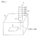
- Fig. 1 is a schematic arrangement diagram illustrating an arrangement of a signal indicator lamp according to a preferred embodiment of the present invention.
- a signal indicator lamp 1 is controlled by a signal lamp control device 2 provided in a production equipment 5.
- the signal lamp control device 2 may be a programmable logic controller (PLC) that controls operation of the production equipment 5.
- PLC programmable logic controller
- the signal lamp control device 2 is a control signal output device that outputs a plurality of control signals to control the signal indicator lamp 1. According to the plurality of control signals, the indication state of the signal indicator lamp 1 changes.
- the signal lamp control device 2 outputs control signals corresponding to a working state of the production equipment 5.
- the control signals may be, for example, signals showing a normal operation state, occurrence of out-of-stock of components, preliminary notification of out-of-stock of components, a request for calling a manager, and occurrence of other abnormalities.
- the signal indicator lamp 1 includes a controlling unit 11 and a signal notifying section 12.
- the signal notifying section 12 includes one or more light emitting units 21, 22, 23, 24, and 25.
- the signal notifying section 12 includes light emitting units 21, 22, 23, 24, and 25 stacked in five stages on the controlling unit 11.
- Each of the light emitting units 21 to 25 includes a light source inside, and is arranged so as to be able to be stacked on or under another light emitting unit and coupled thereto. In other words, each of the light emitting units 21 to 25 can be coupled to another light emitting unit stacked on or under it. Each of the light emitting units 21 to 25 is arranged so as to be able to be stacked on and coupled to the controlling unit 11.
- the term “couple” means mechanical coupling and electrical connection in this case.
- the signal indicator lamp 1 includes one controlling unit 11 and at least one light emitting unit 21 to 25 stacked on the controlling unit 11, and is arranged in a bar shape (or tower shape).
- the signal notifying section 12 can be arranged by stacking one or more light emitting units the number of which is an arbitrary number not less than one, and by attaching or detaching the light emitting units, the number of light emitting units (the number of stages) can be increased or decreased.
- the controlling unit 11 and the respective light emitting units 21 to 25 may be housed in one housing.
- each light emitting unit may be an LED (light-emitting diode).
- each light emitting unit is arranged to be capable of emitting light in a color selected among a plurality of colors.
- each light emitting unit is a full-color type light emitting unit capable of emitting light in three colors.
- Each light emitting unit includes, for example, a green LED as a green light source, a red LED as a red light source, and a blue LED as a blue light source. By making just one of these LEDs emit light, green, red, or blue can be indicated. By making the green LED and the red LED simultaneously emit light, amber light can be emitted.
- Each light emitting unit may not be a full-color type light emitting unit, but may be, for example, a multicolor light emitting-type light emitting unit capable of emitting light in two colors.
- each light emitting unit may include a green LED as a green light source and a red LED as a red light source. By turning on the green LED, green light can be emitted, by turning on the red LED, red light can be emitted, and by simultaneously turning on the green LED and the red LED, orange light can be emitted. Therefore, light emission colors are three colors.
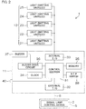
- Fig. 2 is a block diagram illustrating an electrical configuration example of the signal indicator lamp 1.
- the signal lamp control device 2 includes, as described above, for example, a programmable logic controller (PLC).
- the signal lamp control device 2 is connected to the controlling unit 11 by a control signal line 6.
- the controlling unit 11 includes a control section 31, an external input/output section (I/O) 32, an internal input/output section (I/O) 33, a clock 34, a memory 35, a buzzer drive circuit (amplifier) 36, a buzzer (speaker) 37, a DIP switch 38, and a volume adjustment switch 40.
- the control section 31 includes a CPU (Central Processing Unit), and to this control section 31, the external input/output section 32, the internal input/output section 33, the clock 34, the memory 35, the buzzer drive circuit 36, the DIP switch 38, and the volume adjustment switch 40 are connected.
- CPU Central Processing Unit
- the control signal line 6 is connected to the external input/output section 32.
- the light emitting units 21 to 25 are connected to the internal input/output section 33.
- the clock 34 supplies a clock signal for time measurement to the control section 31.
- the buzzer drive circuit 36 is controlled by the control section 31, and supplies driving power to the buzzer 37 to make the buzzer 37 sound as necessary.
- the volume adjustment switch 40 is a switch to be operated by an operator to adjust the volume of the buzzer 37.
- the control section 31 changes power to be supplied from the buzzer drive circuit 36 to the buzzer 37 in response to an operation of the volume adjustment switch 40. Accordingly, the volume of the buzzer 37 is adjusted.
- the volume adjustment switch 40 is, in the present preferred embodiment, a multifunctional switch that provides an operation means for volume adjustment and also provides a light emission color setting operation means to set light emission colors of the light emitting units 21 to 25.
- the volume adjustment switch 40 may be, for example, a momentary-type push button switch.
- the momentary-type switch is a switch that outputs a signal during operation.
- the memory 35 includes, for example, a nonvolatile memory the stored contents of which are rewritable.
- the memory 35 stores control information necessary for controlling the signal notifying section 12 in addition to an operation program of the control section 31.
- the signal lamp control device 2 may output different control signals to a plurality of control signal lines 6, respectively. That is, a plurality of kinds of control signals may be represented by on/off signals output to the plurality of control signal lines 6, respectively.
- the signal lamp control device 2 may output a digital data type control signal to a common control signal line 6.
- the DIP switch 38 may be, for example, a switch to select a buzzer sound at the time of buzzer output.
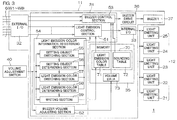
- Fig. 3 is a block diagram illustrating a functional arrangement of the control section 31.
- the control section 31 includes a plurality of functional processing sections that are realized by execution of a predetermined operation program by the CPU. These functional processing sections include a light emission control section 51, a buzzer volume adjusting section 52, a buzzer control section 53, and a light emission color information registering section 54.
- Control information stored in the memory 35 includes an operation table 70 in which operations of the light emitting units 21 to 25 and the buzzer 37 in response to control signals input into the external input/output section 32 are set, and volume data 73 showing set volume of the buzzer 37.
- Control signals to be supplied from the signal lamp control device 2 include a light emission control signal and a buzzer control signal.
- the operation table 70 includes a light emission color table 71 storing light emission color information in which the correspondence relationship between light emission control signals and light emission colors of the light emitting units 21 to 25 is set, and a sounding table 72 storing sounding information in which the correspondence relationship between buzzer control signals and the sounding states of the buzzer 37 is set.
- the light emission color table 71 of these tables is a variable table that is variable.
- the memory 35 storing the light emission color table 71 is an example of the light emission color information storage means.
- the light emission control section 51 controls light emission states of the plurality of light emitting units 21 to 25 according to light emission color information stored in the light emission color table 71 based on a control signal (specifically, light emission control signal) input into the external input/output section 32.
- the light emission control section 51 controls the light emission states of the individual light emitting units 21 to 25 individually. That is, the individual light emitting units 21 to 25 are light emission control target units when the light emission control section 51 controls the signal notifying section 12.
- the buzzer volume adjusting section 52 changes the volume data 73 in steps in response to an operation of the volume adjustment switch 40.
- the volume data 73 is changeable in a plurality of steps (for example, eight steps) between a lower limit (corresponding to, for example, mute) and an upper limit.
- the buzzer volume adjusting section 52 changes the volume data 73 by one step. For example, the buzzer volume adjusting section 52 increases the volume data 73 step by step each time the volume adjustment switch 40 is operated, and when the volume data reaches its upper limit, decreases the volume data 73 step by step, and when the volume data reaches its lower limit, increases the volume data 73 step by step again.
- the buzzer control section 53 controls the buzzer drive circuit 36 so as to make the buzzer 37 produce a sound with a tone designated by the sounding information stored in the sounding table 72 at a volume corresponding to the volume data 73.
- the buzzer control section 53 controls the buzzer drive circuit 36 so that driving power corresponding to the volume data 73 is supplied to the buzzer 37. Therefore, the buzzer volume adjusting section 52 variably sets the driving power to be supplied from the buzzer drive circuit 36 to the buzzer 37 according to variable setting of the volume data 73, and accordingly adjusts the volume.
- the light emission color information registering section 54 is a functional processing section to register light emission color information in the light emission color table 71 based on an operation of the volume adjustment switch 40 in a notification setting mode described later.
- the light emission color information registering section 54 includes a setting object switching section 55, a setting object determining section 56, a light emission color switching section 57, a light emission color determining section 58, and a writing section 59.
- the setting object switching section 55 switches a light emitting unit as a light emission color setting object in response to a short pressing operation (operation in a first manner) of the volume adjustment switch 40.
- the setting object determining section 56 determines a light emitting unit as a light emission color setting object in response to a long pressing operation (operation in a second manner distinguishable from the first manner) of the volume adjustment switch 40.
- the light emission color switching section 57 switches the light emission color of the light emitting unit as the light emission color setting object in response to a short pressing operation (operation in a third manner) of the volume adjustment switch 40 after the light emitting unit as the light emission color setting object is determined.
- the light emission color determining section 58 determines the light emission color of the light emitting unit as the light emission color setting object in response to a long pressing operation (operation in a fourth manner distinguishable from the third manner) of the volume adjustment switch 40.
- the light emission control section 51 controls the light emitting unit selected by the setting object switching section 55 into a predetermined turned-on state (for example, flashing) showing a selected state, and turns on the light emitting unit as the light emission color setting object in the light emission color selected by the light emission color switching section 57.
- a predetermined turned-on state for example, flashing
- the setting object switching section 55 sequentially switches the plurality of light emitting units as the light emission color setting object in response to a short pressing operation (operation in the first manner), and further, can be put into a non-selection state where none of the light emitting units is selected.
- the writing section 59 writes light emission color information showing the light emission color determined by the light emission color determining section 58 in the light emission color table 71 in response to a long pressing operation (operation in a fifth manner distinguishable from the first manner) of the volume adjustment switch 40 when the setting object switching section 55 is in the non-selection state.
- the light emission control section 51 controls at least one of the plurality of light emitting units into a predetermined turned-on state showing the non-selection state.
- the light emission control section 51 may express the non-selection state by turning-off all light emitting units.
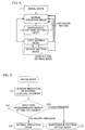
- Fig. 4 is a mode shift diagram illustrating an example of operation modes of the control section 31.
- the operation modes of the control section 31 include an initial mode, a normal operation mode, a maintenance pattern setting mode, and a notification setting mode.
- the initial mode is a mode during a period of shifting from power turning-on to a normal operation mode.
- the control section 31 indicates a version of an internal control program by a turning-on pattern of the signal notifying section 12.
- the mode shifts to the maintenance pattern setting mode.
- the long pressing operation is an operation of continuously operating (in detail, continuously pressing) the volume adjustment switch 40 for a predetermined period of time (for example, 3 seconds) or longer.
- An operation the continuous operation time of which is shorter than the predetermined period of time of the volume adjustment switch 40 is a short pressing operation.
- the normal operation mode is an operation mode in which a notifying operation is performed in response to control signals input into the external input/output section 32.
- the control section 31 controls the operations of the light emitting units 21 to 25 and the buzzer 37 by referring to the operation table 70 in the memory 35 based on input control signals (mainly the functions of the light emission control section 51 and the buzzer control section 53).
- the mode shifts to the maintenance pattern setting mode.
- the maintenance pattern setting mode is a mode in which a kind of maintenance that an operator wants to perform is selected.
- the kind of maintenance can be selected by an operation of the volume adjustment switch 40.
- the kind of maintenance switches in a predetermined order for each short pressing operation.
- the kind of maintenance is determined, and the mode shifts to a corresponding maintenance mode.
- One of the maintenance modes is a notification setting mode.
- a notification setting mode is selected by a short pressing operation of the volume adjustment switch 40, and in this selected state, by performing a long pressing operation of the volume adjustment switch 40, the mode shifts to the notification setting mode.
- the mode automatically returns to the normal operation mode.
- Maintenance modes other than the notification setting mode are a flashing speed selection mode, etc., by way of example.
- the notification setting mode is a mode to set light emission colors of the light emitting units 21 to 25, and this mode is mainly carried out by the function of the light emission color information registering section 54.
- the notification setting mode includes a first setting mode to select a light emitting unit as a setting object, and a second setting mode to set a light emission color of the light emitting unit as the setting object. Immediately after shifting to the notification setting mode, the first setting mode is entered.
- the light emitting unit as the setting object switches in a predetermined order (function of the setting object switching section 55). Accordingly, a light emitting unit that an operator wants to set can be selected. In this selected state, when a long pressing operation of the volume adjustment switch 40 is performed, the light emitting unit being selected is selected and determined as a setting object (function of the setting object determining section 56), and the mode shifts to the second setting mode.
- the light emission color of the light emitting unit as the setting object switches in a predetermined order (function of the light emission color switching section 57). Accordingly, a light emission color can be selected.
- the light emitting unit as the setting object emits light in the selected light emission color (function of the light emission control section 51).
- the light emission color being selected is determined as the light emission color of the light emitting unit as the setting object (function of the light emission color determining section 58).
- the mode shifts to the first setting mode.
- a non-selection state where none of the light emitting units is selected can be selected (function of the setting object switching section 55).
- this non-selection state when a long pressing operation of the volume adjustment switch 40 is performed, setting of the light emission color set after entering the notification setting mode is settled, and written (registered) in the light emission color table (function of the writing section 59).
- the mode shifts to the normal operation mode.
- the mode automatically shifts to the normal operation mode.
- Fig. 5 is a flowchart illustrating an operation example of the control section 31 in the initial mode.
- the control section 31 starts an operation according to the initial mode.
- the control section 31 performs an operation to indicate a version of the internal control program (Step S1). Version indication can be performed by, for example, control of the turning-on pattern of the light emitting units 21 to 25.
- a version is indicated by the light emission color of the light emitting unit 21 of the first stage
- a revision is indicated by the light emission color of the light emitting unit 22 of the second stage.
- the turned-on states of the respective light emitting units and numbers are associated with each other by means of light emission colors and continuous turning-on/flashing, and according to this rule, it is possible that version indication is performed by the light emitting unit 21 of the first stage, and revision indication is performed by the light emitting unit 22 of the second stage. Turning-off of the second stage may indicate revision "0.”
- the light emission luminances of the light emitting units 21 and 22 for version indication are preferably set to approximately 50% on the assumption that the luminance in the full turned-on state is 100% so that this light emission state can be clearly distinguished from a light emission state in normal operation.
- the version indication is performed for a predetermined period of time (for example, 10 seconds).
- the control section 31 monitors whether a long pressing operation for a predetermined period of time (for example, 3 seconds) or longer of the volume adjustment switch 40 is performed (Step S2).
- Step S2 When a long pressing operation is detected during the version indicating operation (Step S2: YES), the mode shifts to the maintenance pattern setting mode (Step S3) after the version indicating operation is ended.
- the mode shifts to the normal operation mode after the version indicating operation is ended (Step S4).
- Fig. 6 is a flowchart illustrating an example of processing that the control section 31 repeats in each predetermined control period in the normal operation mode.
- the control section 31 acquires control signals (a light emission control signal and a buzzer control signal) input into the external input/output section 32 (Step S11). Then, the control section 31 controls the light emission states of the light emitting units 21 to 25 according to the acquired light emission control signal by referring to the light emission color table 71 (Step S12, function of the light emission control section 51). In addition, the control section 31 controls the buzzer 37 according to the acquired buzzer control signal by referring to the sounding table 72 and the volume data 73 (Step S13, function of the buzzer control section 53).
- the control signal line connected to the external input/output section 32 may have light emission control signal wires W1 to W5, buzzer control signal wires W6 and W7, and a common signal wire W8.
- the light emission control section 51 may be programmed so as to interpret signal inputs into the light emission control signal wires W1 to W5 as instructions to perform light emission notification using light in notification colors respectively shown in the following Table 2.
- the buzzer control section 53 may be programmed so as to interpret signal inputs into the buzzer control signal wires W6 and W7 as instructions to perform sounding notification using buzzer sounds respectively shown in the following Table 2.
- the light emission color table 71 may be a table in a form in which with each notification color, the stage number of the light emitting unit for which the corresponding notification color is set as the light emission color is associated as shown in the following Table 3.
- the stage number shows the order number of the stage in which a corresponding light emitting unit is located from the controlling unit 11.
- Wire number Notification method notification color/buzzer sound kind
- Light emission color Notification portion Red 5th stage Amber 4th stage Green 3rd stage Blue 2nd stage White 1 st stage
- the light emission control section 51 identifies a notification color based on the light emission control signal wires W to W5 into which a significant signal has been input (refer to Table 2). Then, the light emission control section 51 identifies a light emitting unit for which the identified notification color has been set as a light emission color by referring to the light emission color table 71 (refer to Table 3). The light emission control section 51 turns on the identified light emitting unit in the light emission color registered in the light emission color table 71. Accordingly, signal indication in the light emission color corresponding to the light emission control signal can be performed.
- the buzzer control section 53 identifies a buzzer sound based on the buzzer control signal wire W6 and W7 into which a significant signal has been input (refer to Table 2). Then, the buzzer control section 53 controls the buzzer drive circuit 36 so that the identified buzzer sound is produced from the buzzer 37 at a volume according to the volume data 73 by referring to the volume data 73. Accordingly, a notification sound corresponding to the buzzer control signal can be produced.
- the light emission color table 71 may store light emission color setting information that associates the same light emission color with a plurality of light emitting units. An example of this is shown in Table 4. [Table 4] Light emission color Notification portion (stage number) Red 4th stage, 5th stage Amber 2nd stage, 3rd stage Green 1st stage Blue 1st stage White 1st to 5th stages
- the light emission control section 15 when receiving a light emission notification instruction that designates red as a notification color, the light emission control section 15 makes both of the light emitting units 24 and 25 of the fourth and fifth stages emit light in red.
- the light emission control section 51 when receiving a light emission notification instruction that designates amber as a notification color, the light emission control section 51 makes both of the light emitting units 22 and 23 of the second and third stages emit light in amber.
- the light emission control section 51 makes the light emitting unit 21 of the first stage emit light in green.
- the light emission control section 51 makes the light emitting unit 21 of the first stage emit light in blue.
- the light emission control section 51 makes the light emitting units 21 to 25 of the first to fifth stages emit light in white.
- the associations between the light emission colors and the light emission portions are variously changeable.
- the light emission control section 51 may be programmed so as to interpret respective input signals into the light emission control signal wires W1 to W5 as light emission notification instructions to make the light emitting unit of any of the stage numbers among the light emitting units 21 to 25 of the five stages emit light as shown in the following Table 5.
- the buzzer control section 53 may be programmed so as to interpret respective signal inputs into the buzzer control signal wires W6 and W7 as instructions to perform sounding notification using buzzer sounds as shown in the following Table 5.
- the light emission color table 71 may be a table in a form in which with the stage number of each light emitting unit, a light emission color set for the light emitting unit of the corresponding stage number is associated as shown in the following Table 6.
- the light emission control section 51 identifies a light emitting unit that should be made to emit light based on the control signal wires W1 to W5 into which a significant signal has been input (refer to Table 4). Then, the light emission control section 51 acquires a light emission color set for the identified light emitting unit by referring to the light emission color table 71 (refer to Table 6). The light emission control section 51 makes the identified light emitting unit emit light in the acquired light emission color. Accordingly, signal indication can be performed by making the light emitting unit of the stage number corresponding to the light emission control signal emit light in the light emission color set in advance.
- the buzzer control section 53 operates in the same manner as described above.
- the light emission color table 71 may store light emission color setting information that associates the same light emission color with light emitting units of different stage numbers. An example of this is shown in the following Table 7. [Table 7] Notification portion (stage number) Light emission color 5th stage Red 4th stage Red 3rd stage Amber 2nd stage Amber 1st stage Green
- the light emission control section 51 when receiving a light emission notification instruction that designates light emission of the fifth stage, the light emission control section 51 makes the light emitting unit 25 of the fifth stage emit light in red. Similarly, when receiving a light emission notification instruction that designates light emission of the fourth stage, the light emission control section 51 makes the light emitting unit 24 of the fourth stage emit light in red.
- the light emission control section 51 makes the light emitting unit 23 of the third stage emit light in amber.
- the light emission control section 51 makes the light emitting unit 22 of the second stage emit light in amber.
- the light emission control section 51 makes the light emitting unit 21 of the first stage emit light in green.
- the associations between the light emission portions (stage numbers) and the light emission colors are variously changeable.
- Step S 14 when an operation of the volume adjustment switch 40 is performed (Step S 14), the buzzer volume adjusting section 52 changes the volume data 73 in response to this operation (Step S15). Accordingly, power to be supplied from the buzzer drive circuit 36 to the buzzer 37 changes, and the volume of the buzzer 37 is changed accordingly.
- the volume of the buzzer 37 may be settable in 8 steps (that may include a mute step). Each time the volume adjustment switch 40 is operated, the control section 31 changes the volume of the buzzer 37 by one step, and for confirmation, may make the buzzer 37 sound at the changed volume.
- Fig. 7 is a flowchart illustrating an operation example of the control section 31 in the maintenance pattern setting mode.
- the control section 31 controls and makes the signal notifying section 12 indicate that the maintenance pattern setting mode has been entered (Step S21).
- the control section 31 makes all light emitting units 21 to 25 flash once in white, and then turns on (continuously turns on) all light emitting units 21 to 25 in the set colors of the light emitting units 21 to 25 of the respective stages.
- the turned-on state at this time is preferably set to a turned-on state, for example, at a luminance of approximately 50% so that this turned-on state can be clearly distinguished from signal indication in the normal operation mode.
- the light emission colors of the respective light emitting units may follow the light emission color table 71.
- light emission colors of white, blue, green, amber, and red may be set in order from the bottom for the respective light emitting units 21 to 25 of the five stages.
- initial values of the light emission colors in the case of four-stage specifications in which the light emitting units are stacked in four stages blue, green, amber, and red may be set from the bottom.
- green, amber, and red may be set in order from the bottom.
- initial values of light emission colors in the case of two-stage specifications green and red may be set in order from the bottom.
- red may be set.
- the control section 31 controls and makes the signal notifying section 12 indicate which of the maintenance patterns among the plurality of maintenance patterns is being selected. For example, when first to fifth maintenance patterns are selectable, a light emitting unit of a corresponding stage number may be put into a flashing state (for example, at a luminance of 50%) and light emitting units of the remaining stages may be put into a continuous turned-on state (for example, at a luminance of 50%). That is, for example, when the second maintenance pattern is selected, the light emitting unit 22 of the second stage may be put into a flashing state. At this time, putting into a flashing state, for example, at a luminance of approximately 50% is preferable so that it can be clearly distinguished from signal indication in the normal operation mode.
- the first maintenance pattern is automatically selected (Step S22), and for example, the light emitting unit 21 of the first stage enters a flashing state at a luminance of 50%.
- the control section 31 further resets the timer for measurement of the automatic return time, and starts the measurement (Step S23).
- the control section 31 measures the time by actuating the internal timer based on a clock signal from the clock 34 (refer to Fig. 2 ). If an operation input of the volume adjustment switch 40 is not detected before the timer measures an elapse of the automatic return time (Step S24: NO), the control section 31 shifts the operation mode to the normal operation mode (Step S25).
- Step S24 When an operation of the volume adjustment switch 40 is detected before the timer measures an elapse of the automatic return time (Step S24: YES), the control section 31 judges whether the operation is a long pressing operation that continues for a predetermined period of time or longer or a short pressing operation duration of which is not longer than the predetermined period of time (Step S26). In the case of the short pressing operation, the control section 31 switches the selection state of the maintenance pattern (Step S27). In detail, each time a short pressing operation of the volume adjustment switch 40 is performed, the control section 31 switches the maintenance pattern selection state among the plurality of maintenance patterns (for example, first to fifth maintenance patterns) in a predetermined order.
- the control section 31 switches the maintenance pattern selection state among the plurality of maintenance patterns (for example, first to fifth maintenance patterns) in a predetermined order.
- the control section 31 controls and makes the signal notifying section 12 indicate a switched maintenance pattern (Step S28). For example, when a short pressing operation of the volume adjustment switch 40 is performed while the second maintenance pattern is selected, the third maintenance pattern is selected, and the light emitting unit 23 of the third stage is controlled into a flashing state at a luminance of 50%, and the remaining light emitting units are controlled into a continuous turned-on state at a luminance of 50%. Light emission colors at this time may follow the light emission color table 71. Thereafter, the control section 31 repeats the operation from Step S23.
- Step S26 When a long pressing operation of the volume adjustment switch 40 is detected while any of the maintenance patterns is selected (Step S26: YES), the control section 31 settles the selection of this maintenance pattern being selected, and shifts to a setting mode following this maintenance pattern (Step S29).
- One of the modes following the plurality of maintenance patterns is the notification setting mode.
- Fig. 8 is a flowchart illustrating an example of processing of the control section 31 in the first setting mode of the notification setting mode.
- the first setting mode is a mode in which a light emitting unit that becomes a light emission color setting object is selected and determined.
- the control section 31 controls and makes the signal notifying section 12 indicate that the first setting mode has been entered (Step S31, function of the light emission control section 51).
- the light emission control section 51 makes all light emitting units 21 to 25 flash twice in white, and then continuously turns on all light emitting units 21 to 25 in the set colors of the light emitting units 21 to 25 of the respective stages.
- the turned-on state at this time is preferably set to turned-on states, for example, at a luminance of approximately 50% so that the turned-on state can be clearly distinguished from signal indication in the normal operation mode.
- the light emission colors of the respective light emitting units may follow the light emission color table 71.
- the control section 31 controls and makes the signal notifying section 12 indicate which of the light emitting units 21 to 25 is being selected as a setting object candidate (function of the light emission control section 51). For example, it is possible that the light emitting unit being selected is put into a flashing state, and the light emitting units of the remaining stages are put into a continuous turned-on state. That is, for example, in a state where the light emitting unit 22 of the second stage is selected, the light emitting unit 22 of the second stage may be put into a flashing state. At this time, putting into a flashing state, for example, at a luminance of approximately 50% is preferable so that it can be clearly distinguished from signal indication in the normal operation mode.
- the light emitting unit 21 of the first stage is automatically selected as a setting object candidate, and for example, the light emitting unit 21 of the first stage enters a flashing state at a luminance of 50% (Step S32).
- the control section 31 further resets the timer for measurement of the automatic return time and starts the measurement (Step S33).
- the light emitting unit as the setting object candidate can be switched by performing a short pressing operation of the volume adjustment switch 40.
- a short pressing operation of the volume adjustment switch 40 each time a short pressing operation of the volume adjustment switch 40 is performed, the light emitting unit as the setting object candidate switches in a predetermined order, and accordingly, an arbitrary light emitting unit can be selected as a setting object candidate.
- a non-selection state (null) where none of the light emitting units is selected can be entered.
- the control section 31 settles this light emitting unit as a setting object and shifts to the first setting mode.
- the control section 31 performs processing to register the light emission color information set in the notification setting mode in the light emission color table.
- the control section 31 judges whether a non-selection state (null) has been entered (Step S34), and performs processing that differs depending on the judgment results. In a state where any of the light emitting units is selected, the control section 31 judges where there is an operation input of the volume adjustment switch 40 before the timer measures an elapse of the automatic return time (Step S35). If an operation input of the volume adjustment switch 40 is not detected before an elapse of the automatic return time is measured (Step S35: NO), the control section 31 shifts the operation mode to the normal operation mode (Step S36).
- Step S35 When an operation of the volume adjustment switch 40 is detected before the timer measures an elapse of the automatic return time (Step S35: YES), the control section 31 judges whether this operation is a long pressing operation or a short pressing operation (Step S37). In the case of a short pressing operation, the control section 31 switches the selection state of the light emitting unit (Step S38, function of the setting object switching section 55). In detail, each time a short pressing operation of the volume adjustment switch 40 is performed, the setting object switching section 55 switches the selection state among the light emitting units 21 to 25 in a predetermined order. Then, the control section 31 controls and makes the signal notifying section 12 indicate a switched light emitting unit as a setting object candidate (Step S39, function of the light emission control section 51).
- the control section 31 repeats the operation from Step S33.
- Step S37 When a long pressing operation of the volume adjustment switch 40 is detected in a state where any of the light emitting units is selected as a setting object candidate (Step S37: YES), the control section 31 settles this light emitting unit being selected as the setting object (Step S40, function of the setting object determining section 56), and shifts to the second setting mode (Step S41).
- Step S34 judges whether there is an operation input of the volume adjustment switch 40 before the timer measures an elapse of the automatic return time (Step S42). If an operation input of the volume adjustment switch 40 is not detected before an elapse of the automatic return time is measured (Step S42: NO), the control section 31 shifts the operation mode to the normal operation mode (Step S43).
- Step S42 When an operation of the volume adjustment switch 40 is detected before the timer measures an elapse of the automatic return time (Step S42: YES), the control section 31 judges whether this operation is a long pressing operation or a short pressing operation (Step S44). In the case of a short pressing operation, the control section 31 switches the selection state of the light emitting unit (Step S38). That is, the non-selection state is changed into a state where any of the light emitting units is selected as a setting object candidate. Thereafter, the control section 31 repeats the operation from Step S39.
- Step S44 when a long pressing operation of the volume adjustment switch 40 is detected (Step S44: YES), the control section 31 writes the setting content in the notification setting mode in the light emission color table (Step S45, function of the writing section 59). Then, the control section 31 controls the signal notifying section 12 to indicate that registration in the light emission color table has been performed (Step S46, function of the light emission control section 51).
- the light emission control section 51 may make all light emitting units 21 to 25 flash at a luminance of 50% for a predetermined period of time (for example, 5 seconds). Thereafter, the control section 31 shifts the operation mode to the normal operation mode (Step S47).
- Fig. 9 is a flowchart illustrating an example of processing of the control section 31 in the second setting mode of the notification setting mode.
- the second setting mode is a mode in which a light emission color of a light emitting unit as a setting object selected and determined in the first setting mode is selected and determined.
- the control section 31 controls and makes the signal notifying section 12 indicate that the second setting mode has been entered (Step S51, function of the light emission control section 51).
- the light emission control section 51 makes all light emitting units 21 to 25 flash three times in white, and then, turns on (continuously turns on) all light emitting units 21 to 25 in set colors of the light emitting units 21 to 25 of the respective stages.
- the turned-on state at this time is preferably set to a turned-on state, for example, at a luminance of approximately 50% so that this turned-on state can be clearly distinguished from signal indication in the normal operation mode.
- the light emission colors of the respective light emitting units may follow the light emission color table 71.
- the control section 31 controls and makes the signal notifying section 12 indicate which of the light emitting units is a setting object (Step S52, function of the light emission control section 51).
- the control section 31 may make the light emitting unit as the setting object flash at a luminance of 50%, and continuously turn on the light emitting units of the remaining stages.
- the light emission colors at this time may follow the light emission color table 71.
- the light emitting unit 22 of the second stage is the setting object, the light emitting unit 22 of the second stage may be put into a flashing state in a light emission color following the setting in the light emission color table.
- control section 31 resets the timer for measurement of the automatic return time and starts the measurement (Step S53), and judges whether there is an operation input of the volume adjustment switch 40 before the timer measures an elapse of the automatic return time (Step S54). If an operation input of the volume adjustment switch 40 is not detected before an elapse of the automatic return time is measured (Step S54: NO), the control section 31 shifts the operation mode to the normal operation mode (Step S55).
- Step S54 When an operation of the volume adjustment switch 40 is detected before the timer measures an elapse of the automatic return time (Step S54: YES), the control section 31 judges whether the operation is a long pressing operation or a short pressing operation (Step S56). In the case of a short pressing operation, the control section 31 switches the light emission color of the light emitting unit (Step S57, function of the light emission color switching section 57). In detail, each time a short pressing operation of the volume adjustment switch 40 is performed, the light emission color switching section 57 switches the light emission color in a predetermined order.
- the control section 31 makes the light emitting unit as the setting object candidate emit light (for example, flash) in the switched light emission color (Step S58, function of the light emission control section 51).
- the light emission color may be switched cyclically in a predetermined order (for example, in the order of red, green, blue, amber, cyan, magenta, white, and red).
- the control section 31 repeats the operation from Step S53.
- Step S56 While the light emitting unit as the setting object emits light (flashes) in any of the light emission colors, that is, in a state where a corresponding emission color is selected, when a long pressing operation of the volume adjustment switch 40 is detected (Step S56: YES), the control section 31 determines this light emission color being selected as the light emission color of the light emitting unit as the setting object (Step S59, function of the light emission color determining section 58). Then, the control section 31 controls the signal notifying section 12 to indicate that the light emission color has been set (Steps S60 and S61, function of the light emission control section 51).
- control section 31 may make all light emitting units 21 to 25 flash in white (Step S60), and then may make the light emitting unit as the setting object flash in the determined light emission color for a predetermined period of time (Step S61) to indicate the determination of the light emission color. Thereafter, the control section 31 shifts the operation mode to the first setting mode, and performs the processing from Step S33 in Fig. 8 .
- the volume adjustment switch 40 provided on the signal indicator lamp 1
- light emission color information for designating light emission colors of the light emitting units 21 to 25 can be registered in the light emission color table.
- the registered light emission color information light emission states of the plurality of light emitting units 21 to 25 are controlled in response to an input control signal. Accordingly, the light emission colors of the light emitting units 21 to 25 can be set by a simple operation, so that an operation to prepare a memory storing light emission color information in advance and a setting operation that is performed by setting a computer for the signal indicator lamp 1 are not needed.
- control section 31 adjusts the volume of the buzzer 37 by controlling the buzzer drive circuit 36 that supplies driving power to the buzzer 37 and variably setting driving power to be supplied from the buzzer drive circuit 36 to the buzzer 37 in response to an operation of the volume adjustment switch 40. Therefore, by using the volume adjustment switch 40 for volume adjustment of the buzzer 37, the light emission colors of the light emitting units 21 to 25 can be set, and the volume adjustment switch 40 can be used as a multifunctional switch. Therefore, without providing a special switch, the light emission colors of the light emitting units 21 to 25 can be set by a simple operation.
- the signal indicator lamp 1 includes the buzzer 37 that is driven by the buzzer drive circuit 36, and the control section 31 makes the buzzer 37 sound by driving the buzzer drive circuit 36 based on an input control signal.
- the buzzer 37 since the buzzer 37 is provided, in normal use, the volume of the buzzer 37 can be adjusted by operating the volume adjustment switch 40.
- the signal indicator lamp 1 does not necessarily have to include the buzzer 37. Even in this case, it is preferable that the signal indicator lamp 1 includes the buzzer drive circuit 36 and the volume adjustment switch 40. By including these, the signal indicator lamp can be adapted to both specifications with a buzzer and specifications without a buzzer. In each of the specifications, by operating the volume adjustment switch 40, the light emission colors of the light emitting units 21 to 25 can be set by a simple operation.
- the light emitting unit as the light emission color setting object in the first setting mode of the notification setting mode, by performing a short pressing operation (operation in the first manner) of the volume adjustment switch 40, the light emitting unit as the light emission color setting object is switched among the plurality of light emitting units 21 to 25, and thereafter, by performing a long pressing operation (operation in the second manner), the light emitting unit as the light emission color setting object can be determined.
- a light emitting unit as the light emission color setting object can be selected and determined among the plurality of light emitting units 21 to 25, and the mode can be shifted to the second setting mode for light emission color setting.
- the light emission color of the light emitting unit as the setting object is switched, and thereafter, by performing a long pressing operation (operation in the fourth manner), the light emission color can be determined.
- one light emission color can be selected and set among the plurality of light emission colors.
- the light emitting unit as the light emission color setting object is controlled into a light emission state showing a selected state (for example, flashing at a luminance of 50%). Further, when setting a light emission color, the light emitting unit as the setting object is made to emit light (flash at a luminance of 50%) in a selected light emission color.
- the light emitting unit in the light emission color setting state can be recognized based on its light emission state. Further, the selected light emission color can be recognized by the light emission color of this light emitting unit. That is, while utilizing the light emitting units as a visual interface, the light emission color of an arbitrary light emitting unit can be set to an arbitrary color by an operation of the volume adjustment switch 40.
- the control section 31 writes light emission color information showing the determined light emission color in the light emission color table. Accordingly, by an operation of the volume adjustment switch 40, the light emission color information can be registered in the light emission color table 71.
- all light emitting units are controlled into a turned-off state. Based on this, an operator can recognize the non-selection state without fail, so that the operator can register the light emission color information in the light emission color table 71 without fail.
- the volume adjustment switch 40 is used as a multifunctional switch; however, a switch other than the volume adjustment switch may be used as a multifunctional switch.
- a multifunctional switch may be provided.
- the individual light emitting units are light emission control target units to be controlled by the control section 31 ; however, the individual light emitting units do not have to be light emission control target units, respectively, and a group of a plurality of light emitting units may be a light emission control target unit. That is, it is also possible that one or more light emitting units constitute a light emission control target unit, and for each light emission control target unit, a light emission color can be set.
- light emitting unit in the preferred embodiment described above may be replaced with “light emission control target unit.”
- the plurality of light emission control target units may consist of the same numbers of light emitting units, respectively, or may include two or more light emission control target units consisting of different numbers of light emitting units, respectively.
- volume adjustment switch 40 is a switch to which two operations of a volume increasing operation and a volume decreasing operation are applicable, the volume increasing operation and the volume decreasing operation may be assigned to an operation to switch a setting object or a light emission color and an operation to determine a setting object or a light emission color, respectively.
Landscapes
- Physics & Mathematics (AREA)
- General Physics & Mathematics (AREA)
- Circuit Arrangement For Electric Light Sources In General (AREA)
- Audible And Visible Signals (AREA)
- Illuminated Signs And Luminous Advertising (AREA)
Abstract
Description
- The present invention relates to a signal indicator lamp including a plurality of light emitting units.
- A signal indicator lamp is arranged so that its turned-on state is controlled based on control signals supplied from a control device such as a programmable logic controller (PLC) that controls mechanical equipment such as production equipment.
- The signal indicator lamp disclosed in
Patent Literature 1 includes a plurality of stacked cells, an LED substrate disposed so as to penetrate through the plurality of cells, and LEDs (light-emitting diodes) mounted to both surfaces of the LED substrate. The LED substrate is provided with red, green, and blue LEDs for each cell. Accordingly, each cell can assume, in addition to a non-turned-on state, turned-on states where it emits light in red, green, blue, amber, purple, light blue, and white. A control circuit to control the LEDs includes a CPU, a flash ROM storing a configuration file, and a memory storing a conversion table. The control circuit is connected to a PLC via a plurality of signal lines, and via these signal lines, control signals are supplied. In the configuration file, a plurality of control signals to be supplied from the PLC via the plurality of signal lines are associated with light emission colors of the cells. The conversion table is a table that the CPU creates based on the configuration file. The conversion table is a table in which the control signals are associated with turned-on states of the LEDs of the respective colors for realizing light emission colors of the respective cells. - When a control signal is input, the CPU controls the LEDs of each cell into turned-on states corresponding to the control signal by referring to the conversion table. Accordingly, each cell can be controlled into a turned-on state (light emission color) set in the configuration file.
- [Patent Literature 1] Japanese Patent Application Publication No.
2012-221793 - In the prior art disclosed in
Patent Literature 1, a configuration file is written in the flash ROM by using a memory card or a USB port. When a memory card is used, a configuration file prepared in advance by an information processing device such as a PC is stored in the memory card, and by inserting the memory card into a card reader, the configuration file is written in the flash ROM. When a USB port is used, the information processing device such as a PC is connected to the USB port by using a cable, and the configuration file is transferred via the cable and written in the flash ROM. - Therefore, for setting the correspondence relationship between the control signals and light emission colors of the respective cells, a troublesome operation using a memory card and an information processing device, etc., is needed, and this requires labor and time.
- Therefore, an object of the present invention is to provide a signal indicator lamp in which light emission colors of light emission control target units can be set by a simple operation.
- The present invention provides a signal indicator lamp including a plurality of light emission control target units each of which emits light in one light emission color selected among a plurality of light emission colors, a light emission color information storage means that variably stores light emission color information of the plurality of light emission control target units, a light emission control means that controls light emission states of the plurality of light emission control target units according to light emission color information stored in the light emission color information storage means based on an input control signal, a multifunctional switch to be operated by an operator, and a light emission color information registration means that registers light emission color information in the light emission color information storage means based on an operation of the multifunctional switch.
- With this arrangement, by operating the multifunctional switch provided on the signal indicator lamp, light emission color information that designates light emission colors of the light emission control target units can be registered in the light emission color information storage means. According to the registered light emission color information, in response to an input control single, light emission states of the plurality of light emission control target units are controlled. Accordingly, light emission colors of the light emission control target units can be set by a simple operation.
- Each light emission control target unit may include one light emitting unit, or may include a plurality of light emitting units. The plurality of light emission control target units may consist of the same numbers of light emitting units, respectively, or may include two or more light emission control target units consisting of different numbers of light emitting units, respectively. Each light emitting unit includes at least one light source.
- A signal indicator lamp according to a preferred embodiment of the present invention further includes a buzzer drive circuit that supplies driving power to a buzzer, and a buzzer volume adjustment means that adjusts the volume of the buzzer by variably setting the driving power to be supplied from the buzzer drive circuit to the buzzer in response to an operation of the multifunctional switch.
- With this arrangement, in a normal use state of the signal indicator lamp, the multifunctional switch can be used as a volume adjustment switch to adjust the volume of the buzzer. In other words, by using the volume adjustment switch, light emission colors of the light emission control target units can be set. Therefore, without providing a special switch, light emission colors of the light emission control target units can be set by a simple operation.
- The signal indicator lamp does not necessarily have to include a buzzer even if it includes a buzzer drive circuit. That is, by arranging the signal indicator lamp to include a buzzer drive circuit and a buzzer volume adjustment means, the signal indicator lamp can be adapted to both specifications with a buzzer and specifications without a buzzer. In each of the specifications, by operating the multifunctional switch, light emission colors of the light emission control target units can be set by a simple operation.
- In a preferred embodiment of the present invention, the light emission color information registration means includes a setting object switching means that switches a light emission control target unit as a light emission color setting object in response to an operation in a first manner of the multifunctional switch, a setting object determination means that determines a light emission control target unit as a light emission color setting object in response to an operation in a second manner distinguishable from the first manner of the multifunctional switch, a light emission color switching means that switches the light emission color of a light emission control target unit as a light emission color setting object in response to an operation in a third manner of the multifunctional switch after the light emission control target unit as the light emission color setting object is determined, and a light emission color determination means that determines the light emission color of the light emission control target unit as the light emission color setting object in response to an operation in a fourth manner distinguishable from the third manner of the multifunctional switch.
- With this arrangement, by performing the operation in the first manner of the multifunctional switch, a light emission control target unit as a light emission color setting object can be switched among the plurality of light emission control target units, and thereafter, by performing the operation in the second manner, the light emission control target unit as the light emission color setting object can be determined. Thus, a light emission control target unit as a light emission color setting object can be selected and determined among the plurality of light emission control target units. Next, by performing the operation in the third manner of the multifunctional switch, the light emission color of the light emission control target unit as the setting object can be switched, and thereafter, by performing the operation in the fourth manner, the light emission color can be determined. Thus, for each light emission control target unit, one light emission color can be selected and set among the plurality of light emission colors.
- In a preferred embodiment of the present invention, the light emission control means controls a light emission control target unit selected by the setting object switching means into a predetermined light emission state showing a selected state, and makes the light emission control target unit as the light emission color setting object emit light in a light emission color selected by the light emission color switching means. With this arrangement, an operator can recognize the light emission control target unit selected as a light emission color setting object by its light emission state. An operator can also recognize the selected light emission color by the light emission color of the selected light emission control target unit. That is, while utilizing the light emission control target units as a visual interface, the light emission color of an arbitrary light emission control target unit can be set to an arbitrary color by an operation of the multifunctional switch.
- In a preferred embodiment of the present invention, the setting object switching means can sequentially switch the plurality of light emission control target units as a light emission color setting object in response to the operation in the first manner, and further, can be put into a non-selection state where none of the light emission control target units is selected. The light emission color information registration means further includes a writing means that writes light emission color information showing a light emission color determined by the light emission color determination means in the light emission color information storage means in response to an operation in a fifth manner distinguishable from the first manner of the multifunctional switch when the setting object switching means is in the non-selection state.
- With this arrangement, by the operation in the first manner of the multifunctional switch, a non-selection state where none of the light emission control target units is selected can be entered, and by performing the operation in the fifth manner of the multifunctional switch in this state, light emission color information can be registered in the light emission color information storage means.
- In a preferred embodiment of the present invention, the light emission control means controls at least one of the plurality of light emission control target units into a predetermined light emission state showing the non-selection state in the non-selection state. With this arrangement, the non-selection state can be recognized by the light emission state of the light emission control target unit. Therefore, an operator can register light emission color information without fail. The light emission state showing the non-selection state may be turned-off for all light emission control target units.
-
- [
Fig. 1] Fig. 1 is a schematic arrangement diagram illustrating an arrangement of a signal indicator lamp according to a preferred embodiment of the present invention. - [
Fig. 2] Fig. 2 is a block diagram illustrating an electrical configuration example of the signal indicator lamp. - [
Fig. 3] Fig. 3 is a block diagram illustrating a functional arrangement of a control section provided in the signal indicator lamp. - [
Fig. 4] Fig. 4 is a mode shift diagram illustrating an example of operation modes of the control section. - [
Fig. 5] Fig. 5 is a flowchart illustrating an operation example of the control section in an initial mode. - [
Fig. 6] Fig. 6 is a flowchart illustrating an example of processing that the control section repeats in each predetermined control period in a normal operation mode. - [
Fig. 7] Fig. 7 is a flowchart illustrating an operation example of the control section in a maintenance pattern setting mode. - [
Fig. 8] Fig. 8 is a flowchart illustrating an example of processing of the control section in a first setting mode of a notification setting mode. - [
Fig. 9] Fig. 9 is a flowchart illustrating an example of processing of the control section in a second setting mode of the notification setting mode. - Hereinafter, a preferred embodiment of the present invention is described in detail with reference to the accompanying drawings.
-
Fig. 1 is a schematic arrangement diagram illustrating an arrangement of a signal indicator lamp according to a preferred embodiment of the present invention. Asignal indicator lamp 1 is controlled by a signallamp control device 2 provided in aproduction equipment 5. The signallamp control device 2 may be a programmable logic controller (PLC) that controls operation of theproduction equipment 5. The signallamp control device 2 is a control signal output device that outputs a plurality of control signals to control thesignal indicator lamp 1. According to the plurality of control signals, the indication state of thesignal indicator lamp 1 changes. The signallamp control device 2 outputs control signals corresponding to a working state of theproduction equipment 5. The control signals may be, for example, signals showing a normal operation state, occurrence of out-of-stock of components, preliminary notification of out-of-stock of components, a request for calling a manager, and occurrence of other abnormalities. - The
signal indicator lamp 1 includes a controllingunit 11 and asignal notifying section 12. Thesignal notifying section 12 includes one or more light emittingunits signal notifying section 12 includeslight emitting units unit 11. - Each of the
light emitting units 21 to 25 includes a light source inside, and is arranged so as to be able to be stacked on or under another light emitting unit and coupled thereto. In other words, each of thelight emitting units 21 to 25 can be coupled to another light emitting unit stacked on or under it. Each of thelight emitting units 21 to 25 is arranged so as to be able to be stacked on and coupled to the controllingunit 11. The term "couple" means mechanical coupling and electrical connection in this case. Thesignal indicator lamp 1 includes one controllingunit 11 and at least onelight emitting unit 21 to 25 stacked on the controllingunit 11, and is arranged in a bar shape (or tower shape). Thesignal notifying section 12 can be arranged by stacking one or more light emitting units the number of which is an arbitrary number not less than one, and by attaching or detaching the light emitting units, the number of light emitting units (the number of stages) can be increased or decreased. The controllingunit 11 and the respectivelight emitting units 21 to 25 may be housed in one housing. - The light source included in each light emitting unit may be an LED (light-emitting diode). In the present preferred embodiment, each light emitting unit is arranged to be capable of emitting light in a color selected among a plurality of colors. In detail, in the present preferred embodiment, each light emitting unit is a full-color type light emitting unit capable of emitting light in three colors. Each light emitting unit includes, for example, a green LED as a green light source, a red LED as a red light source, and a blue LED as a blue light source. By making just one of these LEDs emit light, green, red, or blue can be indicated. By making the green LED and the red LED simultaneously emit light, amber light can be emitted. By making the green LED and the blue LED simultaneously emit light, cyan light can be emitted. By making the red LED and the blue LED simultaneously emit light, magenta light can be emitted. Further, by making the green LED, the red LED, and the blue LED simultaneously emit light, white light can be emitted.
- Each light emitting unit may not be a full-color type light emitting unit, but may be, for example, a multicolor light emitting-type light emitting unit capable of emitting light in two colors. In detail, each light emitting unit may include a green LED as a green light source and a red LED as a red light source. By turning on the green LED, green light can be emitted, by turning on the red LED, red light can be emitted, and by simultaneously turning on the green LED and the red LED, orange light can be emitted. Therefore, light emission colors are three colors.
-
Fig. 2 is a block diagram illustrating an electrical configuration example of thesignal indicator lamp 1. The signallamp control device 2 includes, as described above, for example, a programmable logic controller (PLC). The signallamp control device 2 is connected to the controllingunit 11 by acontrol signal line 6. The controllingunit 11 includes acontrol section 31, an external input/output section (I/O) 32, an internal input/output section (I/O) 33, aclock 34, amemory 35, a buzzer drive circuit (amplifier) 36, a buzzer (speaker) 37, aDIP switch 38, and avolume adjustment switch 40. Thecontrol section 31 includes a CPU (Central Processing Unit), and to thiscontrol section 31, the external input/output section 32, the internal input/output section 33, theclock 34, thememory 35, thebuzzer drive circuit 36, theDIP switch 38, and thevolume adjustment switch 40 are connected. - To the external input/
output section 32, thecontrol signal line 6 is connected. To the internal input/output section 33, thelight emitting units 21 to 25 are connected. Theclock 34 supplies a clock signal for time measurement to thecontrol section 31. Thebuzzer drive circuit 36 is controlled by thecontrol section 31, and supplies driving power to thebuzzer 37 to make thebuzzer 37 sound as necessary. Thevolume adjustment switch 40 is a switch to be operated by an operator to adjust the volume of thebuzzer 37. Thecontrol section 31 changes power to be supplied from thebuzzer drive circuit 36 to thebuzzer 37 in response to an operation of thevolume adjustment switch 40. Accordingly, the volume of thebuzzer 37 is adjusted. Thevolume adjustment switch 40 is, in the present preferred embodiment, a multifunctional switch that provides an operation means for volume adjustment and also provides a light emission color setting operation means to set light emission colors of thelight emitting units 21 to 25. Thevolume adjustment switch 40 may be, for example, a momentary-type push button switch. The momentary-type switch is a switch that outputs a signal during operation. - The
memory 35 includes, for example, a nonvolatile memory the stored contents of which are rewritable. Thememory 35 stores control information necessary for controlling thesignal notifying section 12 in addition to an operation program of thecontrol section 31. - The signal
lamp control device 2 may output different control signals to a plurality ofcontrol signal lines 6, respectively. That is, a plurality of kinds of control signals may be represented by on/off signals output to the plurality ofcontrol signal lines 6, respectively. The signallamp control device 2 may output a digital data type control signal to a commoncontrol signal line 6. - The
DIP switch 38 may be, for example, a switch to select a buzzer sound at the time of buzzer output. -
Fig. 3 is a block diagram illustrating a functional arrangement of thecontrol section 31. Thecontrol section 31 includes a plurality of functional processing sections that are realized by execution of a predetermined operation program by the CPU. These functional processing sections include a lightemission control section 51, a buzzervolume adjusting section 52, abuzzer control section 53, and a light emission colorinformation registering section 54. - Control information stored in the
memory 35 includes an operation table 70 in which operations of thelight emitting units 21 to 25 and thebuzzer 37 in response to control signals input into the external input/output section 32 are set, andvolume data 73 showing set volume of thebuzzer 37. Control signals to be supplied from the signallamp control device 2 include a light emission control signal and a buzzer control signal. The operation table 70 includes a light emission color table 71 storing light emission color information in which the correspondence relationship between light emission control signals and light emission colors of thelight emitting units 21 to 25 is set, and a sounding table 72 storing sounding information in which the correspondence relationship between buzzer control signals and the sounding states of thebuzzer 37 is set. The light emission color table 71 of these tables is a variable table that is variable. Thememory 35 storing the light emission color table 71 is an example of the light emission color information storage means. - The light
emission control section 51 controls light emission states of the plurality of light emittingunits 21 to 25 according to light emission color information stored in the light emission color table 71 based on a control signal (specifically, light emission control signal) input into the external input/output section 32. In the present preferred embodiment, the lightemission control section 51 controls the light emission states of the individuallight emitting units 21 to 25 individually. That is, the individuallight emitting units 21 to 25 are light emission control target units when the lightemission control section 51 controls thesignal notifying section 12. - The buzzer
volume adjusting section 52 changes thevolume data 73 in steps in response to an operation of thevolume adjustment switch 40. Thevolume data 73 is changeable in a plurality of steps (for example, eight steps) between a lower limit (corresponding to, for example, mute) and an upper limit. When thevolume adjustment switch 40 is operated, the buzzervolume adjusting section 52 changes thevolume data 73 by one step. For example, the buzzervolume adjusting section 52 increases thevolume data 73 step by step each time thevolume adjustment switch 40 is operated, and when the volume data reaches its upper limit, decreases thevolume data 73 step by step, and when the volume data reaches its lower limit, increases thevolume data 73 step by step again. When sounding of thebuzzer 37 is instructed by a buzzer control signal, thebuzzer control section 53 controls thebuzzer drive circuit 36 so as to make thebuzzer 37 produce a sound with a tone designated by the sounding information stored in the sounding table 72 at a volume corresponding to thevolume data 73. Thebuzzer control section 53 controls thebuzzer drive circuit 36 so that driving power corresponding to thevolume data 73 is supplied to thebuzzer 37. Therefore, the buzzervolume adjusting section 52 variably sets the driving power to be supplied from thebuzzer drive circuit 36 to thebuzzer 37 according to variable setting of thevolume data 73, and accordingly adjusts the volume. - The light emission color
information registering section 54 is a functional processing section to register light emission color information in the light emission color table 71 based on an operation of thevolume adjustment switch 40 in a notification setting mode described later. The light emission colorinformation registering section 54 includes a settingobject switching section 55, a settingobject determining section 56, a light emissioncolor switching section 57, a light emissioncolor determining section 58, and awriting section 59. - The setting
object switching section 55 switches a light emitting unit as a light emission color setting object in response to a short pressing operation (operation in a first manner) of thevolume adjustment switch 40. The settingobject determining section 56 determines a light emitting unit as a light emission color setting object in response to a long pressing operation (operation in a second manner distinguishable from the first manner) of thevolume adjustment switch 40. The light emissioncolor switching section 57 switches the light emission color of the light emitting unit as the light emission color setting object in response to a short pressing operation (operation in a third manner) of thevolume adjustment switch 40 after the light emitting unit as the light emission color setting object is determined. The light emissioncolor determining section 58 determines the light emission color of the light emitting unit as the light emission color setting object in response to a long pressing operation (operation in a fourth manner distinguishable from the third manner) of thevolume adjustment switch 40. - The light
emission control section 51 controls the light emitting unit selected by the settingobject switching section 55 into a predetermined turned-on state (for example, flashing) showing a selected state, and turns on the light emitting unit as the light emission color setting object in the light emission color selected by the light emissioncolor switching section 57. - The setting
object switching section 55 sequentially switches the plurality of light emitting units as the light emission color setting object in response to a short pressing operation (operation in the first manner), and further, can be put into a non-selection state where none of the light emitting units is selected. Thewriting section 59 writes light emission color information showing the light emission color determined by the light emissioncolor determining section 58 in the light emission color table 71 in response to a long pressing operation (operation in a fifth manner distinguishable from the first manner) of thevolume adjustment switch 40 when the settingobject switching section 55 is in the non-selection state. - In the non-selection state, the light
emission control section 51 controls at least one of the plurality of light emitting units into a predetermined turned-on state showing the non-selection state. For example, the lightemission control section 51 may express the non-selection state by turning-off all light emitting units. -
Fig. 4 is a mode shift diagram illustrating an example of operation modes of thecontrol section 31. The operation modes of thecontrol section 31 include an initial mode, a normal operation mode, a maintenance pattern setting mode, and a notification setting mode. - The initial mode is a mode during a period of shifting from power turning-on to a normal operation mode. In the initial mode, the
control section 31 indicates a version of an internal control program by a turning-on pattern of thesignal notifying section 12. In the initial mode, when a predetermined operation (for example, a long pressing operation) of thevolume adjustment switch 40 is performed, the mode shifts to the maintenance pattern setting mode. The long pressing operation is an operation of continuously operating (in detail, continuously pressing) thevolume adjustment switch 40 for a predetermined period of time (for example, 3 seconds) or longer. An operation the continuous operation time of which is shorter than the predetermined period of time of thevolume adjustment switch 40 is a short pressing operation. - The normal operation mode is an operation mode in which a notifying operation is performed in response to control signals input into the external input/
output section 32. Thecontrol section 31 controls the operations of thelight emitting units 21 to 25 and thebuzzer 37 by referring to the operation table 70 in thememory 35 based on input control signals (mainly the functions of the lightemission control section 51 and the buzzer control section 53). In the normal operation mode, when a predetermined operation (for example, a long pressing operation) of thevolume adjustment switch 40 is performed, the mode shifts to the maintenance pattern setting mode. - The maintenance pattern setting mode is a mode in which a kind of maintenance that an operator wants to perform is selected. The kind of maintenance can be selected by an operation of the
volume adjustment switch 40. In detail, when a short pressing operation of thevolume adjustment switch 40 is performed in the maintenance pattern setting mode, the kind of maintenance switches in a predetermined order for each short pressing operation. When a long pressing operation of thevolume adjustment switch 40 is performed in a state where a desired kind of maintenance is selected, the kind of maintenance is determined, and the mode shifts to a corresponding maintenance mode. There are a plurality of maintenance modes corresponding to the plurality of kinds of maintenance. One of the maintenance modes is a notification setting mode. Therefore, a notification setting mode is selected by a short pressing operation of thevolume adjustment switch 40, and in this selected state, by performing a long pressing operation of thevolume adjustment switch 40, the mode shifts to the notification setting mode. When no operation of thevolume adjustment switch 40 is performed for a predetermined automatic return time (for example, 60 seconds) in the maintenance pattern setting mode, the mode automatically returns to the normal operation mode. Maintenance modes other than the notification setting mode are a flashing speed selection mode, etc., by way of example. - The notification setting mode is a mode to set light emission colors of the
light emitting units 21 to 25, and this mode is mainly carried out by the function of the light emission colorinformation registering section 54. The notification setting mode includes a first setting mode to select a light emitting unit as a setting object, and a second setting mode to set a light emission color of the light emitting unit as the setting object. Immediately after shifting to the notification setting mode, the first setting mode is entered. - In the first setting mode, in response to a short pressing operation of the
volume adjustment switch 40, the light emitting unit as the setting object switches in a predetermined order (function of the setting object switching section 55). Accordingly, a light emitting unit that an operator wants to set can be selected. In this selected state, when a long pressing operation of thevolume adjustment switch 40 is performed, the light emitting unit being selected is selected and determined as a setting object (function of the setting object determining section 56), and the mode shifts to the second setting mode. - In the second setting mode, in response to a short pressing operation, the light emission color of the light emitting unit as the setting object switches in a predetermined order (function of the light emission color switching section 57). Accordingly, a light emission color can be selected. At this time, the light emitting unit as the setting object emits light in the selected light emission color (function of the light emission control section 51). In a state where any of the light emission colors is selected, when a long pressing operation of the
volume adjustment switch 40 is performed, the light emission color being selected is determined as the light emission color of the light emitting unit as the setting object (function of the light emission color determining section 58). When the light emission color is determined, the mode shifts to the first setting mode. - In the first setting mode, by a short pressing operation of the
volume adjustment switch 40, a non-selection state where none of the light emitting units is selected can be selected (function of the setting object switching section 55). In this non-selection state, when a long pressing operation of thevolume adjustment switch 40 is performed, setting of the light emission color set after entering the notification setting mode is settled, and written (registered) in the light emission color table (function of the writing section 59). - Thereafter, the mode shifts to the normal operation mode. In the first setting mode or the second setting mode, when no operation of the
volume adjustment switch 40 is performed for a predetermined automatic return time (for example, 60 seconds), the mode automatically shifts to the normal operation mode. -
Fig. 5 is a flowchart illustrating an operation example of thecontrol section 31 in the initial mode. When the power supply of theproduction equipment 5 is turned on, power is supplied to thesignal indicator lamp 1 by a power supply line (not shown) from theproduction equipment 5. Accordingly, thecontrol section 31 starts an operation according to the initial mode. In detail, after the power supply is turned on, when a predetermined period of time elapses, thecontrol section 31 performs an operation to indicate a version of the internal control program (Step S1). Version indication can be performed by, for example, control of the turning-on pattern of thelight emitting units 21 to 25. In greater detail, it is possible that a version is indicated by the light emission color of thelight emitting unit 21 of the first stage, and a revision is indicated by the light emission color of thelight emitting unit 22 of the second stage. In even greater detail, according to the rule shown in the following Table 1, the turned-on states of the respective light emitting units and numbers are associated with each other by means of light emission colors and continuous turning-on/flashing, and according to this rule, it is possible that version indication is performed by thelight emitting unit 21 of the first stage, and revision indication is performed by thelight emitting unit 22 of the second stage. Turning-off of the second stage may indicate revision "0."[Table 1] Corresponding number 1 Red 2 Green 3 Blue 4 Amber Continuous turning-on 5 Cyan 6 Magenta 7 White 8 Red 9 Green 10 Blue 11 Amber Flashing 12 Cyan 13 Magenta 14 White - For example, by continuously turning on the
light emitting unit 21 of the first stage in red and continuously turning on thelight emitting unit 22 of the second stage in green, "version 1.2" can be indicated. The light emission luminances of thelight emitting units - The version indication is performed for a predetermined period of time (for example, 10 seconds). During this version indicating operation, the
control section 31 monitors whether a long pressing operation for a predetermined period of time (for example, 3 seconds) or longer of thevolume adjustment switch 40 is performed (Step S2). When a long pressing operation is detected during the version indicating operation (Step S2: YES), the mode shifts to the maintenance pattern setting mode (Step S3) after the version indicating operation is ended. When a long pressing operation is not detected during the version indicating operation, the mode shifts to the normal operation mode after the version indicating operation is ended (Step S4). -
Fig. 6 is a flowchart illustrating an example of processing that thecontrol section 31 repeats in each predetermined control period in the normal operation mode. Thecontrol section 31 acquires control signals (a light emission control signal and a buzzer control signal) input into the external input/output section 32 (Step S11). Then, thecontrol section 31 controls the light emission states of thelight emitting units 21 to 25 according to the acquired light emission control signal by referring to the light emission color table 71 (Step S12, function of the light emission control section 51). In addition, thecontrol section 31 controls thebuzzer 37 according to the acquired buzzer control signal by referring to the sounding table 72 and the volume data 73 (Step S13, function of the buzzer control section 53). - For example, as shown in the following Table 2, the control signal line connected to the external input/
output section 32 may have light emission control signal wires W1 to W5, buzzer control signal wires W6 and W7, and a common signal wire W8. In this case, the lightemission control section 51 may be programmed so as to interpret signal inputs into the light emission control signal wires W1 to W5 as instructions to perform light emission notification using light in notification colors respectively shown in the following Table 2. Thebuzzer control section 53 may be programmed so as to interpret signal inputs into the buzzer control signal wires W6 and W7 as instructions to perform sounding notification using buzzer sounds respectively shown in the following Table 2. In this case, the light emission color table 71 may be a table in a form in which with each notification color, the stage number of the light emitting unit for which the corresponding notification color is set as the light emission color is associated as shown in the following Table 3. The stage number shows the order number of the stage in which a corresponding light emitting unit is located from the controllingunit 11.[Table 2] Wire number Notification method (notification color/buzzer sound kind) Light emission control signal wire W1 Red W2 Amber W3 Green W4 Blue W5 White Buzzer control signal wire W6 Buzzer sound 1 W7 Buzzer sound 2 Common wire W8 - [Table 3] Light emission color Notification portion (stage number) Red 5th stage Amber 4th stage Green 3rd stage Blue 2nd stage White 1 st stage - The light
emission control section 51 identifies a notification color based on the light emission control signal wires W to W5 into which a significant signal has been input (refer to Table 2). Then, the lightemission control section 51 identifies a light emitting unit for which the identified notification color has been set as a light emission color by referring to the light emission color table 71 (refer to Table 3). The lightemission control section 51 turns on the identified light emitting unit in the light emission color registered in the light emission color table 71. Accordingly, signal indication in the light emission color corresponding to the light emission control signal can be performed. - The
buzzer control section 53 identifies a buzzer sound based on the buzzer control signal wire W6 and W7 into which a significant signal has been input (refer to Table 2). Then, thebuzzer control section 53 controls thebuzzer drive circuit 36 so that the identified buzzer sound is produced from thebuzzer 37 at a volume according to thevolume data 73 by referring to thevolume data 73. Accordingly, a notification sound corresponding to the buzzer control signal can be produced. - The light emission color table 71 may store light emission color setting information that associates the same light emission color with a plurality of light emitting units. An example of this is shown in Table 4.
[Table 4] Light emission color Notification portion (stage number) Red 4th stage, 5th stage Amber 2nd stage, 3rd stage Green 1st stage Blue 1st stage White 1st to 5th stages - In this case, when receiving a light emission notification instruction that designates red as a notification color, the light emission control section 15 makes both of the
light emitting units emission control section 51 makes both of thelight emitting units emission control section 51 makes thelight emitting unit 21 of the first stage emit light in green. When receiving a light emission notification instruction that designates blue as a notification color, the lightemission control section 51 makes thelight emitting unit 21 of the first stage emit light in blue. When receiving a light emission notification instruction that designates white as a notification color, the lightemission control section 51 makes thelight emitting units 21 to 25 of the first to fifth stages emit light in white. - Besides those above, the associations between the light emission colors and the light emission portions (stage numbers) are variously changeable.
- The light
emission control section 51 may be programmed so as to interpret respective input signals into the light emission control signal wires W1 to W5 as light emission notification instructions to make the light emitting unit of any of the stage numbers among thelight emitting units 21 to 25 of the five stages emit light as shown in the following Table 5. Thebuzzer control section 53 may be programmed so as to interpret respective signal inputs into the buzzer control signal wires W6 and W7 as instructions to perform sounding notification using buzzer sounds as shown in the following Table 5. In this case, the light emission color table 71 may be a table in a form in which with the stage number of each light emitting unit, a light emission color set for the light emitting unit of the corresponding stage number is associated as shown in the following Table 6.[Table 5] Wire number Notification method (notification portion: stage number) Light emission control signal wire W1 5th stage W2 4th stage W3 3rd stage W4 2nd stage W5 1st stage Buzzer control signal wire W6 Buzzer sound 1 W7 Buzzer sound 2 Common wire W8 - [Table 6] Notification portion (stage number) Light emission color 5th stage Red 4th stage Amber 3rd stage Green 2nd stage Blue 1st stage White - The light
emission control section 51 identifies a light emitting unit that should be made to emit light based on the control signal wires W1 to W5 into which a significant signal has been input (refer to Table 4). Then, the lightemission control section 51 acquires a light emission color set for the identified light emitting unit by referring to the light emission color table 71 (refer to Table 6). The lightemission control section 51 makes the identified light emitting unit emit light in the acquired light emission color. Accordingly, signal indication can be performed by making the light emitting unit of the stage number corresponding to the light emission control signal emit light in the light emission color set in advance. - The
buzzer control section 53 operates in the same manner as described above. - The light emission color table 71 may store light emission color setting information that associates the same light emission color with light emitting units of different stage numbers. An example of this is shown in the following Table 7.
[Table 7] Notification portion (stage number) Light emission color 5th stage Red 4th stage Red 3rd stage Amber 2nd stage Amber 1st stage Green - In this case, when receiving a light emission notification instruction that designates light emission of the fifth stage, the light
emission control section 51 makes thelight emitting unit 25 of the fifth stage emit light in red. Similarly, when receiving a light emission notification instruction that designates light emission of the fourth stage, the lightemission control section 51 makes thelight emitting unit 24 of the fourth stage emit light in red. When receiving a light emission notification instruction that designates light emission of the third stage, the lightemission control section 51 makes thelight emitting unit 23 of the third stage emit light in amber. When receiving a light emission notification instruction that designates light emission of the second stage, the lightemission control section 51 makes thelight emitting unit 22 of the second stage emit light in amber. When receiving a light emission notification instruction that designates light emission of the first stage, the lightemission control section 51 makes thelight emitting unit 21 of the first stage emit light in green. - Besides those above, the associations between the light emission portions (stage numbers) and the light emission colors are variously changeable.
- On the other hand, when an operation of the
volume adjustment switch 40 is performed (Step S 14), the buzzervolume adjusting section 52 changes thevolume data 73 in response to this operation (Step S15). Accordingly, power to be supplied from thebuzzer drive circuit 36 to thebuzzer 37 changes, and the volume of thebuzzer 37 is changed accordingly. For example, the volume of thebuzzer 37 may be settable in 8 steps (that may include a mute step). Each time thevolume adjustment switch 40 is operated, thecontrol section 31 changes the volume of thebuzzer 37 by one step, and for confirmation, may make thebuzzer 37 sound at the changed volume. -
Fig. 7 is a flowchart illustrating an operation example of thecontrol section 31 in the maintenance pattern setting mode. When entering the maintenance pattern setting mode, thecontrol section 31 controls and makes thesignal notifying section 12 indicate that the maintenance pattern setting mode has been entered (Step S21). For example, thecontrol section 31 makes all light emittingunits 21 to 25 flash once in white, and then turns on (continuously turns on) alllight emitting units 21 to 25 in the set colors of thelight emitting units 21 to 25 of the respective stages. The turned-on state at this time is preferably set to a turned-on state, for example, at a luminance of approximately 50% so that this turned-on state can be clearly distinguished from signal indication in the normal operation mode. The light emission colors of the respective light emitting units may follow the light emission color table 71. - In the light emission color table 71, for example, as initial values, light emission colors of white, blue, green, amber, and red may be set in order from the bottom for the respective
light emitting units 21 to 25 of the five stages. As initial values of the light emission colors in the case of four-stage specifications in which the light emitting units are stacked in four stages, blue, green, amber, and red may be set from the bottom. Similarly, as initial values of light emission colors in the case of three-stage specifications, green, amber, and red may be set in order from the bottom. Further, as initial values of light emission colors in the case of two-stage specifications, green and red may be set in order from the bottom. As an initial value in the case of one-stage specifications, red may be set. - Next, the
control section 31 controls and makes thesignal notifying section 12 indicate which of the maintenance patterns among the plurality of maintenance patterns is being selected. For example, when first to fifth maintenance patterns are selectable, a light emitting unit of a corresponding stage number may be put into a flashing state (for example, at a luminance of 50%) and light emitting units of the remaining stages may be put into a continuous turned-on state (for example, at a luminance of 50%). That is, for example, when the second maintenance pattern is selected, thelight emitting unit 22 of the second stage may be put into a flashing state. At this time, putting into a flashing state, for example, at a luminance of approximately 50% is preferable so that it can be clearly distinguished from signal indication in the normal operation mode. Immediately after entering the maintenance pattern setting mode, the first maintenance pattern is automatically selected (Step S22), and for example, thelight emitting unit 21 of the first stage enters a flashing state at a luminance of 50%. - The
control section 31 further resets the timer for measurement of the automatic return time, and starts the measurement (Step S23). Thecontrol section 31 measures the time by actuating the internal timer based on a clock signal from the clock 34 (refer toFig. 2 ). If an operation input of thevolume adjustment switch 40 is not detected before the timer measures an elapse of the automatic return time (Step S24: NO), thecontrol section 31 shifts the operation mode to the normal operation mode (Step S25). - When an operation of the
volume adjustment switch 40 is detected before the timer measures an elapse of the automatic return time (Step S24: YES), thecontrol section 31 judges whether the operation is a long pressing operation that continues for a predetermined period of time or longer or a short pressing operation duration of which is not longer than the predetermined period of time (Step S26). In the case of the short pressing operation, thecontrol section 31 switches the selection state of the maintenance pattern (Step S27). In detail, each time a short pressing operation of thevolume adjustment switch 40 is performed, thecontrol section 31 switches the maintenance pattern selection state among the plurality of maintenance patterns (for example, first to fifth maintenance patterns) in a predetermined order. Then, thecontrol section 31 controls and makes thesignal notifying section 12 indicate a switched maintenance pattern (Step S28). For example, when a short pressing operation of thevolume adjustment switch 40 is performed while the second maintenance pattern is selected, the third maintenance pattern is selected, and thelight emitting unit 23 of the third stage is controlled into a flashing state at a luminance of 50%, and the remaining light emitting units are controlled into a continuous turned-on state at a luminance of 50%. Light emission colors at this time may follow the light emission color table 71. Thereafter, thecontrol section 31 repeats the operation from Step S23. - When a long pressing operation of the
volume adjustment switch 40 is detected while any of the maintenance patterns is selected (Step S26: YES), thecontrol section 31 settles the selection of this maintenance pattern being selected, and shifts to a setting mode following this maintenance pattern (Step S29). One of the modes following the plurality of maintenance patterns is the notification setting mode. -
Fig. 8 is a flowchart illustrating an example of processing of thecontrol section 31 in the first setting mode of the notification setting mode. The first setting mode is a mode in which a light emitting unit that becomes a light emission color setting object is selected and determined. When entering the first setting mode, thecontrol section 31 controls and makes thesignal notifying section 12 indicate that the first setting mode has been entered (Step S31, function of the light emission control section 51). For example, the lightemission control section 51 makes all light emittingunits 21 to 25 flash twice in white, and then continuously turns on alllight emitting units 21 to 25 in the set colors of thelight emitting units 21 to 25 of the respective stages. The turned-on state at this time is preferably set to turned-on states, for example, at a luminance of approximately 50% so that the turned-on state can be clearly distinguished from signal indication in the normal operation mode. The light emission colors of the respective light emitting units may follow the light emission color table 71. - Next, the
control section 31 controls and makes thesignal notifying section 12 indicate which of thelight emitting units 21 to 25 is being selected as a setting object candidate (function of the light emission control section 51). For example, it is possible that the light emitting unit being selected is put into a flashing state, and the light emitting units of the remaining stages are put into a continuous turned-on state. That is, for example, in a state where thelight emitting unit 22 of the second stage is selected, thelight emitting unit 22 of the second stage may be put into a flashing state. At this time, putting into a flashing state, for example, at a luminance of approximately 50% is preferable so that it can be clearly distinguished from signal indication in the normal operation mode. Immediately after entering the first setting mode of the notification mode, thelight emitting unit 21 of the first stage is automatically selected as a setting object candidate, and for example, thelight emitting unit 21 of the first stage enters a flashing state at a luminance of 50% (Step S32). - The
control section 31 further resets the timer for measurement of the automatic return time and starts the measurement (Step S33). - The light emitting unit as the setting object candidate can be switched by performing a short pressing operation of the
volume adjustment switch 40. In greater detail, each time a short pressing operation of thevolume adjustment switch 40 is performed, the light emitting unit as the setting object candidate switches in a predetermined order, and accordingly, an arbitrary light emitting unit can be selected as a setting object candidate. Further, in the present preferred embodiment, by a short pressing operation of thevolume adjustment switch 40, a non-selection state (null) where none of the light emitting units is selected can be entered. That is, when repeating a short pressing operation of thevolume adjustment switch 40, the light emitting unit as the setting object candidate switches in the predetermined order, and after a state where a certain light emitting units is selected, a non-selection state is entered. In a state where any of the light emitting units is selected as the setting object candidate, when a long pressing operation of thevolume adjustment switch 40 is detected, thecontrol section 31 settles this light emitting unit as a setting object and shifts to the first setting mode. On the other hand, in the non-selection state, when a long pressing operation of thevolume adjustment switch 40 is performed, thecontrol section 31 performs processing to register the light emission color information set in the notification setting mode in the light emission color table. - Therefore, the
control section 31 judges whether a non-selection state (null) has been entered (Step S34), and performs processing that differs depending on the judgment results. In a state where any of the light emitting units is selected, thecontrol section 31 judges where there is an operation input of thevolume adjustment switch 40 before the timer measures an elapse of the automatic return time (Step S35). If an operation input of thevolume adjustment switch 40 is not detected before an elapse of the automatic return time is measured (Step S35: NO), thecontrol section 31 shifts the operation mode to the normal operation mode (Step S36). - When an operation of the
volume adjustment switch 40 is detected before the timer measures an elapse of the automatic return time (Step S35: YES), thecontrol section 31 judges whether this operation is a long pressing operation or a short pressing operation (Step S37). In the case of a short pressing operation, thecontrol section 31 switches the selection state of the light emitting unit (Step S38, function of the setting object switching section 55). In detail, each time a short pressing operation of thevolume adjustment switch 40 is performed, the settingobject switching section 55 switches the selection state among thelight emitting units 21 to 25 in a predetermined order. Then, thecontrol section 31 controls and makes thesignal notifying section 12 indicate a switched light emitting unit as a setting object candidate (Step S39, function of the light emission control section 51). For example, when a short pressing operation of thevolume adjustment switch 40 is performed while thelight emitting unit 22 of the second stage is selected, thelight emitting unit 23 of the third stage is selected, and thelight emitting unit 23 of the third stage is controlled into a flashing state at a luminance of 50%, and the remaining light emitting units are controlled into a continuous turned-on state at a luminance of 50%. Light emission colors at this time follow the light emission color table. Thereafter, thecontrol section 31 repeats the operation from Step S33. - When a long pressing operation of the
volume adjustment switch 40 is detected in a state where any of the light emitting units is selected as a setting object candidate (Step S37: YES), thecontrol section 31 settles this light emitting unit being selected as the setting object (Step S40, function of the setting object determining section 56), and shifts to the second setting mode (Step S41). - On the other hand, when it is judged that the non-selection state (null) has been entered in Step S34, the
control section 31 judges whether there is an operation input of thevolume adjustment switch 40 before the timer measures an elapse of the automatic return time (Step S42). If an operation input of thevolume adjustment switch 40 is not detected before an elapse of the automatic return time is measured (Step S42: NO), thecontrol section 31 shifts the operation mode to the normal operation mode (Step S43). - When an operation of the
volume adjustment switch 40 is detected before the timer measures an elapse of the automatic return time (Step S42: YES), thecontrol section 31 judges whether this operation is a long pressing operation or a short pressing operation (Step S44). In the case of a short pressing operation, thecontrol section 31 switches the selection state of the light emitting unit (Step S38). That is, the non-selection state is changed into a state where any of the light emitting units is selected as a setting object candidate. Thereafter, thecontrol section 31 repeats the operation from Step S39. - On the other hand, in the non-selection state (null), when a long pressing operation of the
volume adjustment switch 40 is detected (Step S44: YES), thecontrol section 31 writes the setting content in the notification setting mode in the light emission color table (Step S45, function of the writing section 59). Then, thecontrol section 31 controls thesignal notifying section 12 to indicate that registration in the light emission color table has been performed (Step S46, function of the light emission control section 51). In detail, the lightemission control section 51 may make alllight emitting units 21 to 25 flash at a luminance of 50% for a predetermined period of time (for example, 5 seconds). Thereafter, thecontrol section 31 shifts the operation mode to the normal operation mode (Step S47). -
Fig. 9 is a flowchart illustrating an example of processing of thecontrol section 31 in the second setting mode of the notification setting mode. The second setting mode is a mode in which a light emission color of a light emitting unit as a setting object selected and determined in the first setting mode is selected and determined. - When entering the second setting mode, the
control section 31 controls and makes thesignal notifying section 12 indicate that the second setting mode has been entered (Step S51, function of the light emission control section 51). For example, the lightemission control section 51 makes all light emittingunits 21 to 25 flash three times in white, and then, turns on (continuously turns on) alllight emitting units 21 to 25 in set colors of thelight emitting units 21 to 25 of the respective stages. The turned-on state at this time is preferably set to a turned-on state, for example, at a luminance of approximately 50% so that this turned-on state can be clearly distinguished from signal indication in the normal operation mode. The light emission colors of the respective light emitting units may follow the light emission color table 71. - Next, the
control section 31 controls and makes thesignal notifying section 12 indicate which of the light emitting units is a setting object (Step S52, function of the light emission control section 51). For example, thecontrol section 31 may make the light emitting unit as the setting object flash at a luminance of 50%, and continuously turn on the light emitting units of the remaining stages. The light emission colors at this time may follow the light emission color table 71. For example, when thelight emitting unit 22 of the second stage is the setting object, thelight emitting unit 22 of the second stage may be put into a flashing state in a light emission color following the setting in the light emission color table. - Further, the
control section 31 resets the timer for measurement of the automatic return time and starts the measurement (Step S53), and judges whether there is an operation input of thevolume adjustment switch 40 before the timer measures an elapse of the automatic return time (Step S54). If an operation input of thevolume adjustment switch 40 is not detected before an elapse of the automatic return time is measured (Step S54: NO), thecontrol section 31 shifts the operation mode to the normal operation mode (Step S55). - When an operation of the
volume adjustment switch 40 is detected before the timer measures an elapse of the automatic return time (Step S54: YES), thecontrol section 31 judges whether the operation is a long pressing operation or a short pressing operation (Step S56). In the case of a short pressing operation, thecontrol section 31 switches the light emission color of the light emitting unit (Step S57, function of the light emission color switching section 57). In detail, each time a short pressing operation of thevolume adjustment switch 40 is performed, the light emissioncolor switching section 57 switches the light emission color in a predetermined order. Then, by controlling thesignal notifying section 12, thecontrol section 31 makes the light emitting unit as the setting object candidate emit light (for example, flash) in the switched light emission color (Step S58, function of the light emission control section 51). The light emission color may be switched cyclically in a predetermined order (for example, in the order of red, green, blue, amber, cyan, magenta, white, and red). After switching of the light emission color, thecontrol section 31 repeats the operation from Step S53. - While the light emitting unit as the setting object emits light (flashes) in any of the light emission colors, that is, in a state where a corresponding emission color is selected, when a long pressing operation of the
volume adjustment switch 40 is detected (Step S56: YES), thecontrol section 31 determines this light emission color being selected as the light emission color of the light emitting unit as the setting object (Step S59, function of the light emission color determining section 58). Then, thecontrol section 31 controls thesignal notifying section 12 to indicate that the light emission color has been set (Steps S60 and S61, function of the light emission control section 51). In detail, thecontrol section 31 may make alllight emitting units 21 to 25 flash in white (Step S60), and then may make the light emitting unit as the setting object flash in the determined light emission color for a predetermined period of time (Step S61) to indicate the determination of the light emission color. Thereafter, thecontrol section 31 shifts the operation mode to the first setting mode, and performs the processing from Step S33 inFig. 8 . - As described above, according to the present invention, by operating the
volume adjustment switch 40 provided on thesignal indicator lamp 1, light emission color information for designating light emission colors of thelight emitting units 21 to 25 can be registered in the light emission color table. According to the registered light emission color information, light emission states of the plurality of light emittingunits 21 to 25 are controlled in response to an input control signal. Accordingly, the light emission colors of thelight emitting units 21 to 25 can be set by a simple operation, so that an operation to prepare a memory storing light emission color information in advance and a setting operation that is performed by setting a computer for thesignal indicator lamp 1 are not needed. - In addition, the
control section 31 adjusts the volume of thebuzzer 37 by controlling thebuzzer drive circuit 36 that supplies driving power to thebuzzer 37 and variably setting driving power to be supplied from thebuzzer drive circuit 36 to thebuzzer 37 in response to an operation of thevolume adjustment switch 40. Therefore, by using thevolume adjustment switch 40 for volume adjustment of thebuzzer 37, the light emission colors of thelight emitting units 21 to 25 can be set, and thevolume adjustment switch 40 can be used as a multifunctional switch. Therefore, without providing a special switch, the light emission colors of thelight emitting units 21 to 25 can be set by a simple operation. - The
signal indicator lamp 1 according to the present preferred embodiment includes thebuzzer 37 that is driven by thebuzzer drive circuit 36, and thecontrol section 31 makes thebuzzer 37 sound by driving thebuzzer drive circuit 36 based on an input control signal. With this arrangement, since thebuzzer 37 is provided, in normal use, the volume of thebuzzer 37 can be adjusted by operating thevolume adjustment switch 40. - The
signal indicator lamp 1 does not necessarily have to include thebuzzer 37. Even in this case, it is preferable that thesignal indicator lamp 1 includes thebuzzer drive circuit 36 and thevolume adjustment switch 40. By including these, the signal indicator lamp can be adapted to both specifications with a buzzer and specifications without a buzzer. In each of the specifications, by operating thevolume adjustment switch 40, the light emission colors of thelight emitting units 21 to 25 can be set by a simple operation. - Further, in the present preferred embodiment, in the first setting mode of the notification setting mode, by performing a short pressing operation (operation in the first manner) of the
volume adjustment switch 40, the light emitting unit as the light emission color setting object is switched among the plurality of light emittingunits 21 to 25, and thereafter, by performing a long pressing operation (operation in the second manner), the light emitting unit as the light emission color setting object can be determined. Thus, a light emitting unit as the light emission color setting object can be selected and determined among the plurality of light emittingunits 21 to 25, and the mode can be shifted to the second setting mode for light emission color setting. - Then, in the second setting mode, by performing a short pressing operation (operation in the third manner) of the
volume adjustment switch 40, the light emission color of the light emitting unit as the setting object is switched, and thereafter, by performing a long pressing operation (operation in the fourth manner), the light emission color can be determined. Thus, for each light emitting unit, one light emission color can be selected and set among the plurality of light emission colors. - In the present preferred embodiment, the light emitting unit as the light emission color setting object is controlled into a light emission state showing a selected state (for example, flashing at a luminance of 50%). Further, when setting a light emission color, the light emitting unit as the setting object is made to emit light (flash at a luminance of 50%) in a selected light emission color. With this arrangement, the light emitting unit in the light emission color setting state can be recognized based on its light emission state. Further, the selected light emission color can be recognized by the light emission color of this light emitting unit. That is, while utilizing the light emitting units as a visual interface, the light emission color of an arbitrary light emitting unit can be set to an arbitrary color by an operation of the
volume adjustment switch 40. - Further, in the present preferred embodiment, in the first setting mode of the notification setting mode, by a short pressing operation (operation in the first manner) of the
volume adjustment switch 40, the plurality of light emitting units can be sequentially switched as a light emission color setting object, and further, a non-selection state where none of the light emitting units is selected can be entered. In this non-selection state, in response to a long pressing operation (operation in the fifth manner) of thevolume adjustment switch 40, thecontrol section 31 writes light emission color information showing the determined light emission color in the light emission color table. Accordingly, by an operation of thevolume adjustment switch 40, the light emission color information can be registered in the light emission color table 71. - Further, in the present preferred embodiment, in the non-selection state, all light emitting units are controlled into a turned-off state. Based on this, an operator can recognize the non-selection state without fail, so that the operator can register the light emission color information in the light emission color table 71 without fail.
- Although a preferred embodiment of the present invention is described above, the present invention can also be carried out in other modes. For example, in the preferred embodiment described above, the
volume adjustment switch 40 is used as a multifunctional switch; however, a switch other than the volume adjustment switch may be used as a multifunctional switch. In detail, in addition to the volume adjustment switch, a multifunctional switch may be provided. - In the preferred embodiment described above, an example in which the individual light emitting units are light emission control target units to be controlled by the
control section 31 is described; however, the individual light emitting units do not have to be light emission control target units, respectively, and a group of a plurality of light emitting units may be a light emission control target unit. That is, it is also possible that one or more light emitting units constitute a light emission control target unit, and for each light emission control target unit, a light emission color can be set. In this case, "light emitting unit" in the preferred embodiment described above may be replaced with "light emission control target unit." The plurality of light emission control target units may consist of the same numbers of light emitting units, respectively, or may include two or more light emission control target units consisting of different numbers of light emitting units, respectively. - In the preferred embodiment described above, an example in which a long pressing operation and a short pressing operation of the
volume adjustment switch 40 are distinguished from each other is described; however, operations of thevolume adjustment switch 40 are not limited to these operation manners. For example, in place of a short pressing operation/a long pressing operation, other operations such as a single click operation/a double click operation may be performed. When thevolume adjustment switch 40 is a switch to which two operations of a volume increasing operation and a volume decreasing operation are applicable, the volume increasing operation and the volume decreasing operation may be assigned to an operation to switch a setting object or a light emission color and an operation to determine a setting object or a light emission color, respectively. - Besides the above, the present invention can be variously modified in design within the scope of the matters described in the claims.
-
- 1
- Signal indicator lamp
- 2
- Signal lamp control device
- 5
- Production equipment
- 6
- Control signal line W1-W5 Light emission control signal wire W6, W7 Buzzer control signal wire W8 Common signal wire
- 11
- Controlling unit
- 12
- Signal notifying section
- 21-25
- Light emitting unit
- 31
- Control section
- 32
- External input/output section
- 33
- Internal input/output section
- 34
- Clock
- 35
- Memory
- 36
- Buzzer drive circuit
- 37
- Buzzer
- 38
- DIP switch
- 40
- Volume adjustment switch
- 51
- Light emission control section
- 52
- Buzzer volume adjusting section
- 53
- Buzzer control section
- 54
- Light emission color information registering section
- 55
- Setting object switching section
- 56
- Setting object determining section
- 57
- Light emission color switching section
- 58
- Light emission color determining section
- 59
- Writing section
- 70
- Operation table
- 71
- Light emission color table
- 72
- Sounding table
- 73
- Volume data
Claims (6)
- A signal indicator lamp comprising:a plurality of light emission control target units each of which is controlled to emit light in one light emission color selected among a plurality of light emission colors;a light emission color information storage means that variably stores light emission color information of the plurality of light emission control target units;a light emission control means that controls light emission states of the plurality of light emission control target units according to light emission color information stored in the light emission color information storage means based on an input control signal;a multifunctional switch to be operated by an operator; anda light emission color information registration means that registers light emission color information in the light emission color information storage means based on an operation of the multifunctional switch.
- The signal indicator lamp according to Claim 1, further comprising:a buzzer drive circuit that supplies driving power to a buzzer; anda buzzer volume adjustment means that adjusts the volume of the buzzer by variably setting the driving power to be supplied from the buzzer drive circuit to the buzzer in response to an operation of the multifunctional switch.
- The signal indicator lamp according to Claim 1 or 2, wherein
the light emission color information registration means includes
a setting object switching means that switches a light emission control target unit as a light emission color setting object in response to an operation in a first manner of the multifunctional switch;
a setting object determination means that determines a light emission control target unit as a light emission color setting object in response to an operation in a second manner distinguishable from the first manner of the multifunctional switch;
a light emission color switching means that switches the light emission color of a light emission control target unit as a light emission color setting object in response to an operation in a third manner of the multifunctional switch after the light emission control target unit as the light emission color setting object is determined; and
a light emission color determination means that determines the light emission color of the light emission control target unit as the light emission color setting object in response to an operation in a fourth manner distinguishable from the third manner of the multifunctional switch. - The signal indicator lamp according to Claim 3, wherein the light emission control means controls a light emission control target unit selected by the setting object switching means into a predetermined light emission state showing a selected state, and makes the light emission control target unit as the light emission color setting object emit light in a light emission color selected by the light emission color switching means.
- The signal indicator lamp according to Claim 3 or 4, wherein
the setting object switching means can sequentially switch the plurality of light emission control target units as a light emission color setting object in response to the operation in the first manner, and further, can be put into a non-selection state where none of the light emission control target units is selected, and
the light emission color information registration means further includes
a writing means that writes light emission color information showing a light emission color determined by the light emission color determination means in the light emission color information storage means in response to an operation in a fifth manner distinguishable from the first manner of the multifunctional switch when the setting object switching means is in the non-selection state. - The signal indicator lamp according to Claim 5, wherein the light emission control means controls at least one of the plurality of light emission control target units into a predetermined light emission state showing the non-selection state.
Applications Claiming Priority (1)
| Application Number | Priority Date | Filing Date | Title |
|---|---|---|---|
| PCT/JP2013/063052 WO2014181425A1 (en) | 2013-05-09 | 2013-05-09 | Signal display lamp |
Publications (3)
| Publication Number | Publication Date |
|---|---|
| EP2996442A1 true EP2996442A1 (en) | 2016-03-16 |
| EP2996442A4 EP2996442A4 (en) | 2016-12-28 |
| EP2996442B1 EP2996442B1 (en) | 2018-05-02 |
Family
ID=51866928
Family Applications (1)
| Application Number | Title | Priority Date | Filing Date |
|---|---|---|---|
| EP13883908.9A Not-in-force EP2996442B1 (en) | 2013-05-09 | 2013-05-09 | Signal display lamp |
Country Status (3)
| Country | Link |
|---|---|
| EP (1) | EP2996442B1 (en) |
| JP (1) | JP5967457B2 (en) |
| WO (1) | WO2014181425A1 (en) |
Cited By (4)
| Publication number | Priority date | Publication date | Assignee | Title |
|---|---|---|---|---|
| US10475299B2 (en) | 2015-07-20 | 2019-11-12 | Banner Engineering Corporation | Modular indicator |
| WO2019241382A1 (en) * | 2018-06-12 | 2019-12-19 | Banner Engineering Corporation | Modular indicator |
| EP3945215A1 (en) | 2020-07-28 | 2022-02-02 | Husqvarna Ab | Control unit for a pump |
| US11971288B2 (en) | 2020-10-29 | 2024-04-30 | Patlite Corporation | Level meter and method of setting the level meter |
Families Citing this family (6)
| Publication number | Priority date | Publication date | Assignee | Title |
|---|---|---|---|---|
| JP6667096B2 (en) * | 2015-10-30 | 2020-03-18 | 株式会社パトライト | Signal indicator |
| JP2018142458A (en) * | 2017-02-28 | 2018-09-13 | 株式会社ルミカ | Light-emitting tool |
| JP7001990B2 (en) * | 2017-07-18 | 2022-01-20 | パナソニックIpマネジメント株式会社 | Notification system |
| KR102158854B1 (en) * | 2019-12-03 | 2020-09-22 | (주)노바코스 | School zone accident detection system |
| CN112261768B (en) * | 2020-11-03 | 2023-12-19 | 广东好太太智能家居有限公司 | Lamp strip color control method and system, intelligent terminal and storage device |
| JP7726162B2 (en) * | 2022-09-08 | 2025-08-20 | 三菱電機株式会社 | STACKED SIGNAL INDICATOR SWITCHING DEVICE, STACKED SIGNAL INDICATOR WITH SWITCHING FUNCTION, PRODUCTION DEVICE, AND METHOD FOR PRODUCING SEMICONDUCTOR DEVICE |
Family Cites Families (5)
| Publication number | Priority date | Publication date | Assignee | Title |
|---|---|---|---|---|
| JP2000353401A (en) * | 1999-06-10 | 2000-12-19 | Arrow Denshi Kogyo Kk | Signal indicator |
| JP2003249383A (en) * | 2002-02-25 | 2003-09-05 | Patoraito:Kk | Failure diagnosis circuit for LED indicator |
| JP5491013B2 (en) * | 2008-09-08 | 2014-05-14 | 新明和工業株式会社 | Lighting equipment |
| DE102008055798A1 (en) * | 2008-11-04 | 2010-05-06 | Werma Holding Gmbh + Co. Kg | Warning light with a base unit and at least one light unit |
| JP2012221793A (en) * | 2011-04-11 | 2012-11-12 | Digital Electronics Corp | Signal lamp control device, device for creating data for signal light control, and programs therefor |
-
2013
- 2013-05-09 JP JP2015515694A patent/JP5967457B2/en active Active
- 2013-05-09 EP EP13883908.9A patent/EP2996442B1/en not_active Not-in-force
- 2013-05-09 WO PCT/JP2013/063052 patent/WO2014181425A1/en not_active Ceased
Cited By (8)
| Publication number | Priority date | Publication date | Assignee | Title |
|---|---|---|---|---|
| US10475299B2 (en) | 2015-07-20 | 2019-11-12 | Banner Engineering Corporation | Modular indicator |
| US10984636B2 (en) | 2015-07-20 | 2021-04-20 | Banner Engineering Corporation | Modular indicator |
| US11580828B2 (en) | 2015-07-20 | 2023-02-14 | Banner Engineering Corporation | Modular indicator |
| USD1018347S1 (en) | 2015-07-20 | 2024-03-19 | Banner Engineering Corporation | Indicator light module |
| WO2019241382A1 (en) * | 2018-06-12 | 2019-12-19 | Banner Engineering Corporation | Modular indicator |
| EP3945215A1 (en) | 2020-07-28 | 2022-02-02 | Husqvarna Ab | Control unit for a pump |
| WO2022022870A1 (en) | 2020-07-28 | 2022-02-03 | Husqvarna Ab | Control unit for a pump |
| US11971288B2 (en) | 2020-10-29 | 2024-04-30 | Patlite Corporation | Level meter and method of setting the level meter |
Also Published As
| Publication number | Publication date |
|---|---|
| EP2996442A4 (en) | 2016-12-28 |
| WO2014181425A1 (en) | 2014-11-13 |
| EP2996442B1 (en) | 2018-05-02 |
| JP5967457B2 (en) | 2016-08-10 |
| JPWO2014181425A1 (en) | 2017-02-23 |
Similar Documents
| Publication | Publication Date | Title |
|---|---|---|
| EP2996442B1 (en) | Signal display lamp | |
| EP1694099B1 (en) | LED driver device | |
| EP3713379B1 (en) | Emission control system using barcode information | |
| JP5387355B2 (en) | shelf | |
| EP2731407A2 (en) | Lighting control device and lighting control system | |
| KR100488340B1 (en) | Remote monitoring and controlling system for remotely monitoring and controlling illumination loads | |
| US5557300A (en) | Functional display apparatus | |
| JP5963032B2 (en) | Signal indicator lamp and computer program therefor | |
| US20040140776A1 (en) | Control device for the actuation of lamps | |
| EP4156863B1 (en) | Illumination control device and illumination system | |
| JP2017068896A (en) | Dimming system | |
| JP7515073B2 (en) | Wireless communication device, wireless communication system, control system, and load control system | |
| JP6705349B2 (en) | Lighting system, plant growing lighting system, lighting equipment | |
| JP2552212B2 (en) | Display panel brightness adjustment method | |
| JPH06204910A (en) | Radio communication equipment | |
| JP7381538B2 (en) | Lighting control equipment and lighting systems | |
| CN117311531A (en) | A touch display chip and LED integrated machine | |
| JP4915908B2 (en) | Lighting control terminal | |
| CN109885190A (en) | A kind of luminescent control system and control method of computer peripheral | |
| JP2006003750A (en) | Led lighting fixture | |
| KR102232870B1 (en) | Tunnel lamp control circuit and method of operating the same | |
| KR20100094406A (en) | Control method for generating varying colored lights in keyboard and self-luminous keyboard for realizing the same method | |
| KR200436334Y1 (en) | Multicolored Light Bar Digital Indicator | |
| JPH01133192U (en) | ||
| CN117612479A (en) | Selection circuit, LED display device and LED lamp strip |
Legal Events
| Date | Code | Title | Description |
|---|---|---|---|
| PUAI | Public reference made under article 153(3) epc to a published international application that has entered the european phase |
Free format text: ORIGINAL CODE: 0009012 |
|
| 17P | Request for examination filed |
Effective date: 20150820 |
|
| AK | Designated contracting states |
Kind code of ref document: A1 Designated state(s): AL AT BE BG CH CY CZ DE DK EE ES FI FR GB GR HR HU IE IS IT LI LT LU LV MC MK MT NL NO PL PT RO RS SE SI SK SM TR |
|
| AX | Request for extension of the european patent |
Extension state: BA ME |
|
| DAX | Request for extension of the european patent (deleted) | ||
| RAP1 | Party data changed (applicant data changed or rights of an application transferred) |
Owner name: PATLITE CORPORATION |
|
| A4 | Supplementary search report drawn up and despatched |
Effective date: 20161129 |
|
| RIC1 | Information provided on ipc code assigned before grant |
Ipc: F21S 2/00 20160101ALI20161123BHEP Ipc: F21V 23/00 20150101ALI20161123BHEP Ipc: F21W 111/00 20060101ALI20161123BHEP Ipc: H05B 33/08 20060101AFI20161123BHEP Ipc: G08B 5/00 20060101ALI20161123BHEP Ipc: G08B 3/00 20060101ALI20161123BHEP Ipc: H05B 37/02 20060101ALI20161123BHEP |
|
| REG | Reference to a national code |
Ref country code: DE Ref legal event code: R079 Ref document number: 602013037100 Country of ref document: DE Free format text: PREVIOUS MAIN CLASS: H05B0037020000 Ipc: H05B0033080000 |
|
| RIC1 | Information provided on ipc code assigned before grant |
Ipc: G08B 3/00 20060101ALI20170502BHEP Ipc: H05B 37/02 20060101ALI20170502BHEP Ipc: H05B 33/08 20060101AFI20170502BHEP Ipc: F21W 111/00 20060101ALI20170502BHEP Ipc: F21S 2/00 20160101ALI20170502BHEP Ipc: G08B 5/00 20060101ALI20170502BHEP Ipc: F21V 23/00 20150101ALI20170502BHEP |
|
| 17Q | First examination report despatched |
Effective date: 20170526 |
|
| GRAP | Despatch of communication of intention to grant a patent |
Free format text: ORIGINAL CODE: EPIDOSNIGR1 |
|
| INTG | Intention to grant announced |
Effective date: 20180129 |
|
| GRAS | Grant fee paid |
Free format text: ORIGINAL CODE: EPIDOSNIGR3 |
|
| GRAA | (expected) grant |
Free format text: ORIGINAL CODE: 0009210 |
|
| AK | Designated contracting states |
Kind code of ref document: B1 Designated state(s): AL AT BE BG CH CY CZ DE DK EE ES FI FR GB GR HR HU IE IS IT LI LT LU LV MC MK MT NL NO PL PT RO RS SE SI SK SM TR |
|
| REG | Reference to a national code |
Ref country code: GB Ref legal event code: FG4D |
|
| REG | Reference to a national code |
Ref country code: CH Ref legal event code: EP Ref country code: AT Ref legal event code: REF Ref document number: 996617 Country of ref document: AT Kind code of ref document: T Effective date: 20180515 |
|
| REG | Reference to a national code |
Ref country code: DE Ref legal event code: R096 Ref document number: 602013037100 Country of ref document: DE Ref country code: IE Ref legal event code: FG4D |
|
| REG | Reference to a national code |
Ref country code: NL Ref legal event code: MP Effective date: 20180502 |
|
| REG | Reference to a national code |
Ref country code: LT Ref legal event code: MG4D |
|
| PG25 | Lapsed in a contracting state [announced via postgrant information from national office to epo] |
Ref country code: SE Free format text: LAPSE BECAUSE OF FAILURE TO SUBMIT A TRANSLATION OF THE DESCRIPTION OR TO PAY THE FEE WITHIN THE PRESCRIBED TIME-LIMIT Effective date: 20180502 Ref country code: ES Free format text: LAPSE BECAUSE OF FAILURE TO SUBMIT A TRANSLATION OF THE DESCRIPTION OR TO PAY THE FEE WITHIN THE PRESCRIBED TIME-LIMIT Effective date: 20180502 Ref country code: LT Free format text: LAPSE BECAUSE OF FAILURE TO SUBMIT A TRANSLATION OF THE DESCRIPTION OR TO PAY THE FEE WITHIN THE PRESCRIBED TIME-LIMIT Effective date: 20180502 Ref country code: FI Free format text: LAPSE BECAUSE OF FAILURE TO SUBMIT A TRANSLATION OF THE DESCRIPTION OR TO PAY THE FEE WITHIN THE PRESCRIBED TIME-LIMIT Effective date: 20180502 Ref country code: BG Free format text: LAPSE BECAUSE OF FAILURE TO SUBMIT A TRANSLATION OF THE DESCRIPTION OR TO PAY THE FEE WITHIN THE PRESCRIBED TIME-LIMIT Effective date: 20180802 Ref country code: NO Free format text: LAPSE BECAUSE OF FAILURE TO SUBMIT A TRANSLATION OF THE DESCRIPTION OR TO PAY THE FEE WITHIN THE PRESCRIBED TIME-LIMIT Effective date: 20180802 |
|
| PG25 | Lapsed in a contracting state [announced via postgrant information from national office to epo] |
Ref country code: LV Free format text: LAPSE BECAUSE OF FAILURE TO SUBMIT A TRANSLATION OF THE DESCRIPTION OR TO PAY THE FEE WITHIN THE PRESCRIBED TIME-LIMIT Effective date: 20180502 Ref country code: HR Free format text: LAPSE BECAUSE OF FAILURE TO SUBMIT A TRANSLATION OF THE DESCRIPTION OR TO PAY THE FEE WITHIN THE PRESCRIBED TIME-LIMIT Effective date: 20180502 Ref country code: RS Free format text: LAPSE BECAUSE OF FAILURE TO SUBMIT A TRANSLATION OF THE DESCRIPTION OR TO PAY THE FEE WITHIN THE PRESCRIBED TIME-LIMIT Effective date: 20180502 Ref country code: GR Free format text: LAPSE BECAUSE OF FAILURE TO SUBMIT A TRANSLATION OF THE DESCRIPTION OR TO PAY THE FEE WITHIN THE PRESCRIBED TIME-LIMIT Effective date: 20180803 Ref country code: NL Free format text: LAPSE BECAUSE OF FAILURE TO SUBMIT A TRANSLATION OF THE DESCRIPTION OR TO PAY THE FEE WITHIN THE PRESCRIBED TIME-LIMIT Effective date: 20180502 |
|
| REG | Reference to a national code |
Ref country code: CH Ref legal event code: PL |
|
| REG | Reference to a national code |
Ref country code: AT Ref legal event code: MK05 Ref document number: 996617 Country of ref document: AT Kind code of ref document: T Effective date: 20180502 |
|
| REG | Reference to a national code |
Ref country code: BE Ref legal event code: MM Effective date: 20180531 |
|
| PG25 | Lapsed in a contracting state [announced via postgrant information from national office to epo] |
Ref country code: PL Free format text: LAPSE BECAUSE OF FAILURE TO SUBMIT A TRANSLATION OF THE DESCRIPTION OR TO PAY THE FEE WITHIN THE PRESCRIBED TIME-LIMIT Effective date: 20180502 Ref country code: SK Free format text: LAPSE BECAUSE OF FAILURE TO SUBMIT A TRANSLATION OF THE DESCRIPTION OR TO PAY THE FEE WITHIN THE PRESCRIBED TIME-LIMIT Effective date: 20180502 Ref country code: CZ Free format text: LAPSE BECAUSE OF FAILURE TO SUBMIT A TRANSLATION OF THE DESCRIPTION OR TO PAY THE FEE WITHIN THE PRESCRIBED TIME-LIMIT Effective date: 20180502 Ref country code: DK Free format text: LAPSE BECAUSE OF FAILURE TO SUBMIT A TRANSLATION OF THE DESCRIPTION OR TO PAY THE FEE WITHIN THE PRESCRIBED TIME-LIMIT Effective date: 20180502 Ref country code: RO Free format text: LAPSE BECAUSE OF FAILURE TO SUBMIT A TRANSLATION OF THE DESCRIPTION OR TO PAY THE FEE WITHIN THE PRESCRIBED TIME-LIMIT Effective date: 20180502 Ref country code: AT Free format text: LAPSE BECAUSE OF FAILURE TO SUBMIT A TRANSLATION OF THE DESCRIPTION OR TO PAY THE FEE WITHIN THE PRESCRIBED TIME-LIMIT Effective date: 20180502 Ref country code: EE Free format text: LAPSE BECAUSE OF FAILURE TO SUBMIT A TRANSLATION OF THE DESCRIPTION OR TO PAY THE FEE WITHIN THE PRESCRIBED TIME-LIMIT Effective date: 20180502 |
|
| REG | Reference to a national code |
Ref country code: DE Ref legal event code: R097 Ref document number: 602013037100 Country of ref document: DE |
|
| REG | Reference to a national code |
Ref country code: IE Ref legal event code: MM4A |
|
| PG25 | Lapsed in a contracting state [announced via postgrant information from national office to epo] |
Ref country code: LI Free format text: LAPSE BECAUSE OF NON-PAYMENT OF DUE FEES Effective date: 20180531 Ref country code: CH Free format text: LAPSE BECAUSE OF NON-PAYMENT OF DUE FEES Effective date: 20180531 Ref country code: SM Free format text: LAPSE BECAUSE OF FAILURE TO SUBMIT A TRANSLATION OF THE DESCRIPTION OR TO PAY THE FEE WITHIN THE PRESCRIBED TIME-LIMIT Effective date: 20180502 Ref country code: IT Free format text: LAPSE BECAUSE OF FAILURE TO SUBMIT A TRANSLATION OF THE DESCRIPTION OR TO PAY THE FEE WITHIN THE PRESCRIBED TIME-LIMIT Effective date: 20180502 |
|
| PLBE | No opposition filed within time limit |
Free format text: ORIGINAL CODE: 0009261 |
|
| STAA | Information on the status of an ep patent application or granted ep patent |
Free format text: STATUS: NO OPPOSITION FILED WITHIN TIME LIMIT |
|
| PG25 | Lapsed in a contracting state [announced via postgrant information from national office to epo] |
Ref country code: MC Free format text: LAPSE BECAUSE OF FAILURE TO SUBMIT A TRANSLATION OF THE DESCRIPTION OR TO PAY THE FEE WITHIN THE PRESCRIBED TIME-LIMIT Effective date: 20180502 Ref country code: LU Free format text: LAPSE BECAUSE OF NON-PAYMENT OF DUE FEES Effective date: 20180509 |
|
| 26N | No opposition filed |
Effective date: 20190205 |
|
| GBPC | Gb: european patent ceased through non-payment of renewal fee |
Effective date: 20180802 |
|
| PG25 | Lapsed in a contracting state [announced via postgrant information from national office to epo] |
Ref country code: FR Free format text: LAPSE BECAUSE OF NON-PAYMENT OF DUE FEES Effective date: 20180702 Ref country code: IE Free format text: LAPSE BECAUSE OF NON-PAYMENT OF DUE FEES Effective date: 20180509 |
|
| PG25 | Lapsed in a contracting state [announced via postgrant information from national office to epo] |
Ref country code: BE Free format text: LAPSE BECAUSE OF NON-PAYMENT OF DUE FEES Effective date: 20180531 Ref country code: SI Free format text: LAPSE BECAUSE OF FAILURE TO SUBMIT A TRANSLATION OF THE DESCRIPTION OR TO PAY THE FEE WITHIN THE PRESCRIBED TIME-LIMIT Effective date: 20180502 |
|
| PG25 | Lapsed in a contracting state [announced via postgrant information from national office to epo] |
Ref country code: GB Free format text: LAPSE BECAUSE OF NON-PAYMENT OF DUE FEES Effective date: 20180802 |
|
| REG | Reference to a national code |
Ref country code: DE Ref legal event code: R079 Ref document number: 602013037100 Country of ref document: DE Free format text: PREVIOUS MAIN CLASS: H05B0033080000 Ipc: H05B0045000000 |
|
| PG25 | Lapsed in a contracting state [announced via postgrant information from national office to epo] |
Ref country code: AL Free format text: LAPSE BECAUSE OF FAILURE TO SUBMIT A TRANSLATION OF THE DESCRIPTION OR TO PAY THE FEE WITHIN THE PRESCRIBED TIME-LIMIT Effective date: 20180502 |
|
| PG25 | Lapsed in a contracting state [announced via postgrant information from national office to epo] |
Ref country code: MT Free format text: LAPSE BECAUSE OF NON-PAYMENT OF DUE FEES Effective date: 20180509 |
|
| PG25 | Lapsed in a contracting state [announced via postgrant information from national office to epo] |
Ref country code: TR Free format text: LAPSE BECAUSE OF FAILURE TO SUBMIT A TRANSLATION OF THE DESCRIPTION OR TO PAY THE FEE WITHIN THE PRESCRIBED TIME-LIMIT Effective date: 20180502 |
|
| PG25 | Lapsed in a contracting state [announced via postgrant information from national office to epo] |
Ref country code: PT Free format text: LAPSE BECAUSE OF FAILURE TO SUBMIT A TRANSLATION OF THE DESCRIPTION OR TO PAY THE FEE WITHIN THE PRESCRIBED TIME-LIMIT Effective date: 20180502 |
|
| PG25 | Lapsed in a contracting state [announced via postgrant information from national office to epo] |
Ref country code: CY Free format text: LAPSE BECAUSE OF FAILURE TO SUBMIT A TRANSLATION OF THE DESCRIPTION OR TO PAY THE FEE WITHIN THE PRESCRIBED TIME-LIMIT Effective date: 20180502 Ref country code: MK Free format text: LAPSE BECAUSE OF NON-PAYMENT OF DUE FEES Effective date: 20180502 Ref country code: HU Free format text: LAPSE BECAUSE OF FAILURE TO SUBMIT A TRANSLATION OF THE DESCRIPTION OR TO PAY THE FEE WITHIN THE PRESCRIBED TIME-LIMIT; INVALID AB INITIO Effective date: 20130509 |
|
| PG25 | Lapsed in a contracting state [announced via postgrant information from national office to epo] |
Ref country code: IS Free format text: LAPSE BECAUSE OF FAILURE TO SUBMIT A TRANSLATION OF THE DESCRIPTION OR TO PAY THE FEE WITHIN THE PRESCRIBED TIME-LIMIT Effective date: 20180902 |
|
| P01 | Opt-out of the competence of the unified patent court (upc) registered |
Effective date: 20230321 |
|
| PGFP | Annual fee paid to national office [announced via postgrant information from national office to epo] |
Ref country code: DE Payment date: 20220630 Year of fee payment: 11 |
|
| REG | Reference to a national code |
Ref country code: DE Ref legal event code: R119 Ref document number: 602013037100 Country of ref document: DE |
|
| PG25 | Lapsed in a contracting state [announced via postgrant information from national office to epo] |
Ref country code: DE Free format text: LAPSE BECAUSE OF NON-PAYMENT OF DUE FEES Effective date: 20241203 |