EP2996402A1 - Telematic system with multiple network access devices in a multi-network environment - Google Patents
Telematic system with multiple network access devices in a multi-network environment Download PDFInfo
- Publication number
- EP2996402A1 EP2996402A1 EP14184557.8A EP14184557A EP2996402A1 EP 2996402 A1 EP2996402 A1 EP 2996402A1 EP 14184557 A EP14184557 A EP 14184557A EP 2996402 A1 EP2996402 A1 EP 2996402A1
- Authority
- EP
- European Patent Office
- Prior art keywords
- network
- nad
- nads
- provider
- terminal system
- Prior art date
- Legal status (The legal status is an assumption and is not a legal conclusion. Google has not performed a legal analysis and makes no representation as to the accuracy of the status listed.)
- Granted
Links
Images

Classifications
-
- H—ELECTRICITY
- H04—ELECTRIC COMMUNICATION TECHNIQUE
- H04L—TRANSMISSION OF DIGITAL INFORMATION, e.g. TELEGRAPHIC COMMUNICATION
- H04L67/00—Network arrangements or protocols for supporting network services or applications
- H04L67/01—Protocols
- H04L67/12—Protocols specially adapted for proprietary or special-purpose networking environments, e.g. medical networks, sensor networks, networks in vehicles or remote metering networks
-
- H—ELECTRICITY
- H04—ELECTRIC COMMUNICATION TECHNIQUE
- H04M—TELEPHONIC COMMUNICATION
- H04M1/00—Substation equipment, e.g. for use by subscribers
- H04M1/72—Mobile telephones; Cordless telephones, i.e. devices for establishing wireless links to base stations without route selection
- H04M1/724—User interfaces specially adapted for cordless or mobile telephones
- H04M1/72403—User interfaces specially adapted for cordless or mobile telephones with means for local support of applications that increase the functionality
-
- H—ELECTRICITY
- H04—ELECTRIC COMMUNICATION TECHNIQUE
- H04W—WIRELESS COMMUNICATION NETWORKS
- H04W4/00—Services specially adapted for wireless communication networks; Facilities therefor
- H04W4/02—Services making use of location information
- H04W4/021—Services related to particular areas, e.g. point of interest [POI] services, venue services or geofences
-
- H—ELECTRICITY
- H04—ELECTRIC COMMUNICATION TECHNIQUE
- H04L—TRANSMISSION OF DIGITAL INFORMATION, e.g. TELEGRAPHIC COMMUNICATION
- H04L67/00—Network arrangements or protocols for supporting network services or applications
- H04L67/01—Protocols
- H04L67/02—Protocols based on web technology, e.g. hypertext transfer protocol [HTTP]
- H04L67/025—Protocols based on web technology, e.g. hypertext transfer protocol [HTTP] for remote control or remote monitoring of applications
-
- H—ELECTRICITY
- H04—ELECTRIC COMMUNICATION TECHNIQUE
- H04L—TRANSMISSION OF DIGITAL INFORMATION, e.g. TELEGRAPHIC COMMUNICATION
- H04L67/00—Network arrangements or protocols for supporting network services or applications
- H04L67/01—Protocols
- H04L67/12—Protocols specially adapted for proprietary or special-purpose networking environments, e.g. medical networks, sensor networks, networks in vehicles or remote metering networks
- H04L67/125—Protocols specially adapted for proprietary or special-purpose networking environments, e.g. medical networks, sensor networks, networks in vehicles or remote metering networks involving control of end-device applications over a network
-
- H—ELECTRICITY
- H04—ELECTRIC COMMUNICATION TECHNIQUE
- H04W—WIRELESS COMMUNICATION NETWORKS
- H04W48/00—Access restriction; Network selection; Access point selection
- H04W48/18—Selecting a network or a communication service
-
- H—ELECTRICITY
- H04—ELECTRIC COMMUNICATION TECHNIQUE
- H04W—WIRELESS COMMUNICATION NETWORKS
- H04W76/00—Connection management
- H04W76/10—Connection setup
Definitions
- the present invention relates to telematic systems, in particular, automotive telematic systems, wherein a plurality of Network Access Devices is provided for a variety of applications making use of one or more media in a multi-network environment.
- telematics means the integrated application of telecommunications and informatics, whereby technologies for sending, receiving and storing information via telecommunication devices are put into operation for realization, for example, of home and business applications.
- vehicular infotainment and telematics are offered via multiple devices both installed in the vehicle and mobile devices carried by a user and possibly connected to a vehicle communication system.
- mobile devices are Personal Digital Assistants and mobile phones.
- NADs network access devices
- the NADs may belong to different providers proving services with different payment and roaming and availability schemes/rules.
- providers may apply rules among each other thus generating consortiums of networks which can be considered from the point of view of a single NAD as a "home network” or "preferable roaming network”.
- the general management of the connections and usages of the multiple NADs and different provider networks is very involved and not realized in a satisfying manner nowadays considering the possible varieties of applying the above mentioned schemes and rules.
- the claimed computer-implemented method for controlling a terminal system comprises the steps of reading information on the physical and/or logical location of the terminal system; reading user configurations and content provider service layer agreements (SLAs); based on the read information, user configurations and content provider SLAs creating associations between applications to be run on the NADs, the NADs and the multiple provider networks; and based on the created associations and the information on the physical and/or logical location of the terminal system selecting one of the NADs and one of the provider networks for running one of the applications on the selected NAD and connecting the selected NAD with the selected provider network.
- SLAs content provider service layer agreements
- the provider networks may comprise any wide-area network like the Universal Mobile Telecommunications System (UMTS) network and/or a Global System for Mobile (GSM) Communications network (for example, 3G or 4G), etc.
- the NADs may be connected to the Internet under the control of the computer system.
- NADs may comprise mobile device as mobile phones or built-in devices fixedly installed in the terminal system. "Running applications” and “running services” are used interchangeable in the present application.
- the application may include internet communication and telephony.
- the computer-implemented method may be implemented in a computer system installed in any kind of vehicle, for example, an automobile.
- the computer system is part of an in-vehicle communication system.
- the computer system may enable the possibility to connect multiple NADs which can be applied as a single modem from the point of view of the applications in the car thereby increasing the effective bandwidth for the applications running their data over the NADs and guaranteeing voice and packet-based (non-voice) data parallelism for applications associated with data and/or voice contents.
- the computer system itself may not be enabled to establish a data communication connection with a provider network but may be configured to use the capability of the NADs to connect to the provider networks and manage the NADs as a bundled plurality of connections.
- the management logic for the NADs may be configured due to network consortium rules to select most suitable visible GSM or WLAN network of reach so that best performance for the application may be achieved at lowest cost.
- performance and costs of applications run on NADs can be optimized due to provider configurations by applying provider rules for the selection of NADs and provider networks, for example.
- restrictions for the usage of NADs and provider networks due to certain area- or country specific regulations can be taken into account.
- information on the physical location of the terminal system have to be provided.
- the physical location may be determined by a GPS means, for example.
- the inventive method not only the physical location can be considered when selecting NADs and provider networks but additionally or alternatively the logical location may be taken into account, i.e. the logical location is identified by the provider signature of the mobile networks visible for the NAD mobile networks, i.e.
- MNC Mobile Network Code
- MCC Mobile Country Code
- SSID Service Set Identifier
- the NADs and provider networks are established.
- association it is meant assignment of individual NADs to applications or mapping between individual NADs and applications to be run on them (and the respective media used by an application) and allowed connections of the NADs with the provider networks, respectively.
- information included in the user configurations and SLAs is read that allow for assigning a particular one of the NADs to some particular application and media.
- the method may comprise generating for each of a plurality of applications and the associated media a list of operable NADs.
- the information comprises particular constraints that, in principle, can be provided by a manufacturer, a user and/or a provider of a service carried on the provider network.
- At least part of the information may be stored in a database of the terminal system.
- the information may particularly comprise a prioritization scheme of associations. For example, if more than one NAD is suitable for a particular application and media each of these NADs can be given some priority value such that in the case that all or some of these NADs are actually available for the application / media the available NAD with the highest priority can be selected.
- the associations between applications to be run on the NADs, the NADs and the multiple provider networks can be created based on device/network configurations stored in the NADs and read in addition to the user configurations and SLAs.
- the previously mentioned user configurations and SLAs that may be stored in a database of the terminal system can be matched with the device/network configurations stored in the NADs and rules for the selection of provider networks for individual NADs, for example, stored in the database can be modified in accordance with rules for the selection of provider networks stored in the NADs or vice versa.
- Rules of one of the user configurations, SLAs and device/network configurations may overrule rules of another one of the user configurations, SLAs and device/network configurations.
- User configurations, SLAs and device/network configurations stored in the NADs can include information on the identification of provider networks available in particular geographical areas and/or access providers associated with the NADs. They can include information on the identification of provider networks available in particular geographical areas and/or access providers associated with the NADs and may include defining that particularly ones of the NADs and/or particular one of the provider networks to be selected in particular countries.
- Device/network configurations can be provided by providers via the provider networks and can comprise SLAs.
- the inventive method may particularly allow for the selection of provider networks and NADs via service application logic comprised in the terminal system, for example, comprised in the computer system (see detailed description below).
- SLA service layer agreements
- An SLA is part of the contract between the service consumer and service provider and formally defines the level of service. Desired functional requirements as well as quality attribute requirements can be described in a service level in the SLA.
- An SLA sets the expectations of both the service consumer and the service provider. It is common for service providers to deliver services at different levels of quality based on the cost paid for a service. An SLA is valuable for helping all parties understand the tradeoffs inherent between cost, schedule, and quality because their relationship is stated explicitly.
- a properly specified SLA describes each service offered and may addresses questions of how delivery of the service at the specified level of quality will become realized, which metrics will be collected, who will collect the metrics and how actions are to be taken when the service is not delivered at the specified level of quality and who is responsible for doing them, penalties for failure to deliver the service at the specified level of quality, how and whether the SLA will evolve as technology changes, etc.
- SLAs may be assigned to applications defining whether an application is allowed by a particular provider.
- the terminal system understands and makes use of the SLAs.
- constraints with respect to the associations of NADs with providers are taken into account and particular applications and NADs are associated with each other based on the SLAs and such constraints.
- a user may upload his/her own user configurations (rules) for the management of the NAD and provider network in the terminal system.
- Such user configurations comprise logics for associating applications, NADs and provider networks.
- a positive logic can be employed in the configurations and SLAs defining that particularly ones of the NADs and/or particular one of the provider networks are to be selected in particular countries.
- a negative logic can be employed in the configurations and SLAs defining that particularly ones of the NADs and/or particular ones of the provider networks are not to be selected in particular countries.
- selection rules include that a first NAD is selected and at least one second NAD is not selected when it is determined that the terminal system is in a first country and in all other countries at least one third NAD is selected or no NAD is selected at all.
- Other selection rules may include that
- the inventive method may comprise running an application on a first NAD connected to the provider network and subsequently changing connection of the provider network to a second NAD and continuing running the application on the second NAD.
- Users and providers can prioritize NADs and provider networks by means of the user configurations and SLAs, respectively.
- the above-described steps of claim 1 are performed at a first physical location and the method further comprises moving the terminal system from the first physical location to a second physical location different from the first physical location and newly selecting a particular NAD and a particular provider network for running a particular one of the applications on the newly selected NAD and connecting the newly selected NAD with the newly selected provider network based on the created associations and the information on the physical location and/or logical location of the terminal system.
- the selection of the NADs and provider networks can dynamically be changed according to the movement of the terminal system from one location to another, for example, from one country to another, and, thus, the temporally changing physical and logical locations.
- the following further steps are comprised in the computer-implemented method for controlling a terminal system: Based on the created associations and the information on the physical and/or logical location of the terminal system one of the NADs and one of the provider networks for running one of the applications on the selected NAD are selected. If allowed by an interface of the selected NAD, connection of the selected NAD with the selected provider network is enforced and if it is not allowed by the interface of the selected NAD, operation of the application on the selected NAD is forbidden or at least restricted.
- a computer program product comprising one or more computer readable media having computer-executable instructions for performing the steps of the method according to one of the above-described examples.
- a terminal system in particular, an automotive terminal system installed in a vehicle, configured for connection to multiple provider networks, comprising multiple network access devices, NADs, configured for running applications; a computer system configured for reading information on the physical and/or logical location of the terminal system; reading user configurations and content provider service layer agreements; based on the read information, user configurations and content provider service layer agreements creating associations between applications to be run on the NADs, the NADs and the multiple provider networks; and based on the created associations and the information on the physical and/or logical location of the terminal system selecting a particular NAD and a particular provider network for running a particular one of the applications on the selected NAD and connecting the selected NAD to the selected provider network.
- NADs network access devices
- the computer system may be further configured to create the associations based on device/network configurations stored in the NADs and read by the computer system.
- the terminal system may further comprise a database configured for storing at least part of the information and wherein the computer system is configured to read the at least part of the information from the database.
- the terminal system can be an automotive terminal system installed in an automobile. All examples of the method for controlling a terminal system described above can be implemented in the terminal system.
- the present invention can be incorporated in an automotive telematic system.
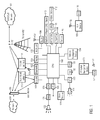
- An example of an automotive telematic system is shown in Figure 1 .
- Components 100 to 145 and 170 to 182 are installed in a vehicle, while components 150 to 161 are external components which are not part of the automotive telematic system but may interact with some of the telematic components of the vehicle.
- a vehicle equipped with a telematic system may contain a display 104, as a visual front end interface located in the vehicle.
- the user may also be able to interact with the interface via a touch sensitive screen, via pressing a button, via audible speech and speech synthesis, or other HMI (Human-Machine-Interaction) components known in the art.
- Interaction via audible speech and speech synthesis or analysis may be via a microphone 131 and an A/D converter 130 for receiving input from the user and via a D/A converter 120, an amplifier 121, and one or several speakers 122 for giving output to the user.
- the visual front end interface may be part of a head-unit for a centralized interaction of the user with the telematic system or separate from one or more dedicated head-units 105, e.g., for interaction of the user with audio or telephony components of the telematic system.
- a central processing unit 100 controls at least a portion of the operation of the telematic system.
- the current invention is not limited to this, but may provide at least one further processing unit assigned to a specific telematic component or a group of telematic components, as for instance a CPU 141 provided with a video display 142, possibly as part of a rear seat entertainment system for displaying movies from a storage device, like a hard disk drive 140.
- the processing unit allows on-board processing of instructions, commands, and routines, particularly as part of an application component of the telematic system.
- the processing unit 100 may further be connected to both non-persistent and persistent storage devices 140.
- the non-persistent storage device is random access memory (RAM) and the persistent storage device is a hard disk drive (HDD) or flash memory.
- the processing unit 100 may also be provided with a number of different inputs allowing the user to interface with the processing unit.
- a microphone 131, an auxiliary input 132, a USB input 123, a GPS input 133, and a Bluetooth input 102 are all provided.
- An input selector may be provided to allow the user to swap between various inputs. Input to the microphone 131 is converted from analog to digital by an A/D converter 130 before being passed to the processing unit.
- Outputs from the telematic system may include, but are not limited to, a video display 124 and a speaker 122 or stereo/surround system output.
- the speaker may be connected to an amplifier 121 and may receive its signal from the processing unit 100 through a digital-to-analog converter 120.
- Output can also be made via the Bluetooth transceiver 102 with a Bluetooth antenna 103 to a remote Bluetooth device such as a personal navigation device 170 with a Bluetooth antenna 172. Communication with a personal navigation device can also be achieved via USB connectors 123 and 171.
- the telematic system may further comprise a vehicle navigation device 134, which may interact with the GPS unit 133 and/or a mobile network 160 (provider network) via a base station 150 and a multi-band antenna 110 or a mobile terminal 111.
- the processing unit has not own access to a provider network but rather wireless data connection to the provider network is merely offered by wirelessly connected or fixedly installed NADs.
- the mobile terminal 111 being an example for an NAD, may particularly be a cell phone, smart phone, PDA, or the like and may be connected to the processing unit 100 either directly, via a USB connector 123, or via the Bluetooth transceiver 102 with its antenna 103.
- the multi-band antenna 110 may exchange data with the processing unit 100 either through a wire or wirelessly through a modem 101.
- the base station 150 and the network 160 are not part of the telematic system but provided outside the vehicle.
- the base station 150 may be a WiFi access point.
- Data may be communicated between the central processing unit 100 and the network 160 utilizing, for instance, a data-plan, data over voice, or DTMF tones associated with the mobile terminal.
- Both multi-band antenna 110 and the mobile terminal 111 may exchange data bi-directionally with the base station or WiFi access point 150.
- the modem 101 may also communicate directly with a network 160 through communications with a cellular tower 150.
- the modem 101 may be a USB cellular modem and the communication may be cellular communication.
- the processing unit 100 is provided with an operating system including an API to communicate with modem application software.
- the modem application software may access an embedded module or firmware on the Bluetooth transceiver 102 to complete wireless communication with a remote Bluetooth transceiver (such as that of the mobile terminal 111).
- the mobile terminal 111 may include a modem for voice band or broadband data communication. If the user has a data-plan associated with the mobile terminal 111, it is possible that the data-plan allows for broadband transmission and the telematic system could use a much wider bandwidth (speeding up data transfer).
- the mobile terminal 111 may be replaced with a cellular communication device (e.g., and without limitation, a modem 101), that is installed in the vehicle.
- the mobile terminal 111 may be replaced with a wireless local area network (LAN) device capable of communication over, for example, an 802.11g network (i.e., WiFi) or a WiMax network.
- LAN wireless local area network
- incoming data can be passed through the mobile terminal 111 via a data-over-voice or data-plan, through the on-board Bluetooth transceiver 102 and into the central processing unit 100.
- Data may be stored on the HDD 140 or in the RAM 140 or any other storage media until such time as the data is no longer needed.
- the HDD 140 or other storage media may in particular be used as the memory for storing generated log files until the reporter component transmits them to an external analyzer component. This transfer to an external analyzer component may be performed via the modem 101, the multi-band antenna 110, the Bluetooth transceiver 102, or the mobile terminal 111, e.g., to a mobile network 160 or a wireless network.
- the central processing unit may further be in communication with a variety of other auxiliary devices 180. These devices can be connected through wireless 182 or wired 181 connections (such as a USB connection). Also, or alternatively, the CPU 100 may be connected to a vehicle based wireless router 106, using for example a WiFi transceiver 107. This could allow the CPU to connect to remote networks in range of the local router 106.
- the processing unit 100 may further interact with a radio, a CD player, or a DVD player 143 to provide audio and/or video to the stereo system 122 and/or a video display 142.
- Audio and/or video may also be provided via the multi-band antenna 110 or the mobile terminal 111 from a mobile network 160, wireless network, or digital broadcast provider network 161 (Digital Audio Broadcast, Digital Video Broadcast) via a broadcast transmitter 151 outside the vehicle.
- Audio and video data may be downloaded or streamed through the above described connections. In the case of a download, the data may be temporarily or persistently stored in the HDD 140 or other storage device.
- a further processing unit 141 may later read the stored data from the HDD 140 and provide video and/or audio service through the vehicle's speaker system 122 or a video display 142.
- the processing unit 100 may further interact with a microphone 131 and the vehicle's speaker system 122 to provide hands-free telephony, e.g., via the mobile terminal 111. Similarly the processing unit 100 may interact with the mobile terminal 111 and vehicle diagnostics (not shown) to send an emergency call or a breakdown call (see further below).
- the processing unit 100 may also interact with an engine control unit (ECU) 144 to control engine parameters or monitor the vehicle's engine.
- the processing unit 100 may interact with a powertrain control module (PCM) 144 and a series of sensor systems 145, like for instance but without limitation, a tire pressure monitoring system, a road condition sensor, a parking sensor, a temperature sensor, an ambient light sensor, and the like.
- Wired communications within the automotive telematic system may be carried out using MOST (Media Oriented Systems Transport), CAN (Controller Area Network), IEEE 1394, or other technologies known in the art.
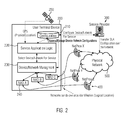
- FIG. 2 shows a particular kind of service network architecture wherein the invention can be implemented.
- a terminal system 200 installed in an automobile according to an example of the invention is provided.
- the terminal system 200 comprises a configuration database 210.
- a user of the terminal system 200 as well as a service provider 300 may upload management rules for applications to be run on NADs, NADs and provider networks 400 to the configuration database 210.
- these rules can be implemented in user configurations and provider SLAs, respectively.
- the terminal system 200 comprises some service application logic 220.
- the service application logic 220 may be comprised in a central processing unit and is configured to control associations between applications, NADs and provider networks based on the information stored in the configuration database 210.
- the service application logic 220 can control connection of NADs to provider networks 400 that are connected with the service provider 300 via a physical network 500.
- the provider networks 400 may comprise technologies like Wireless Local Area Network (WLAN) and/or a General Packet Radios Service (GPRS) network and/or a Global System for Mobile Communications (GSM) network and/or a Universal Mobile Telecommunications System (UMTS) and/or Long-Term-Evolution (LTE) network. All mentioned above technologies belong to IEEE (Institute of Electrical and Electronics Engineers) or 3GPP (3rd Generation Partnership Project) standardization efforts and details thereof can be referred to at the respective standardisation board/-s.
- WLAN Wireless Local Area Network
- GPRS General Packet Radios Service
- GSM Global System for Mobile Communications
- UMTS Universal Mobile Telecommunications System
- LTE Long-Term-Evolution
- the data exchanged via the provider networks 400 can be, in general, IP-data that can be static data like text or dynamic like voice, video, etc., or any digitally coded data like GSM-voice or SMS-text, depending on the used coding and protocols for these information types.
- the service provider 300 may upload configurations/rules in the configuration database 210 via a provider network 400 and the physical network 500.
- the service application logic 220 cooperates with a device/network management unit 230 in a way that it evaluates which networks are currently visible for the NADs and which NADs are currently available.
- the device/network management unit 230 collects the information on the NADs and Networks availability and reports this data to the application logic 220. It (230) also provides to the application logic (220) an interface whereby a specific network for an NAD and a specific NAD can be selected.
- the service application logic 220 may than select for its media the most suitable network and NAD as defined via the configuration rules of the service provider 300 by forcing the NAD to attach to a specific network and use the respectively selected NAD with the respectively selected network
- the device/network management unit 230 is directly connected with NADs 240, for example, mobile phones or PDAs.
- NADs 240 for example, mobile phones or PDAs.
- the service application logic 220 controls connection of NAD A with provider network Z, NAD B with provider network Y and NAD C with provider network X.
- the respective connections can particularly be controlled by the service application logic 220 based on information on the physical location obtained by a GPS means 250, for example, and the logical location provided by the provider networks in form of area identification (codes).
- the NADs 240 represent network access interfaces for connection with the provider networks 400 for applications running on the NADs 240 or a computational unit (for example, the central processing unit wherein the service application logic 220 is comprised in) of the terminal system.
- the NADs may belong to different service providers 300 and may be associated with different payment schemes and roaming rules.
- Both a user of the terminal system 200 and a service provider 300 providing services for the terminal system of the automobile can define rules for the optimal selection of the NADs for offered services depending on the physical area wherein the terminal system 200 is located and/or the available provider networks 400. These rules can be uploaded in the configuration database 210 and accessed by the service application logic 220 and device/network management unit 230.
- the individual NADs 240 may be provided with internally stored rules in form of or comprised in device/network configurations for the automatic selection of one of multiple network technologies (for example, GSM 3G or 4G).
- the NADs 240 can be configured to inform the service application logic 220 about their individual capabilities and configurations, for example, for the network management. Rules stored in the NADs 240 and the configuration database 210 can be matched by the service application logic 220.
- the service application logic 220 may modify rules stored in the NADs 240 according to rules stored in the configuration database 210 or vice versa.
- the service application logic 220 may take over full control of the NAD 240 and adapt it according to the rules uploaded in the configuration database 210 by a user and/or service provider 300. If a particular NAD 240 does not allow full management of the same from the service application logic 220, the service application logic 220 may adapt associations of applications, NADs 240 and provider networks 400 to the automatic network management rules stored in the NAD 240 or may exclude the NAD 240 from services, if its configuration does not fit to the configuration/SLAs stored in the configuration database 210 by a user and/or service provider 300 at least at particular physical locations of the terminal system 200.
- rules for the selection of associations of NADs 240 with provider networks 400 stored in the configuration database 210 by a user and/or service provider 300 are mentioned.
- exemplary rules may read:
- a purely negative logic defining only areas and provider networks that are not allowed to be used may be advantageous in terms of shorter descriptions.
- SLA devices are ordered due to their required order of application. It is up to the content provider and the user how to prioritize devices and networks, and it is up to the provided HMIs for such actions, how the respective data is input into the system.
- An exemplary formal format protocol of such an SLA is defined as it shall be applied within the system application logic after being translated from a HMI or Data-Base input of user or provider configuration. However, the format is general enough to be also applied in any software entity associated with device and network configurations.
- ABNF Augmented Backus-Naur Form
- Figure 3 represents a flow diagram illustrating an example of the inventive method for controlling a terminal system based on provider SLAs, user configurations and device/network configurations.
- Associations between applications, NADs and provider networks can be defined in the SLAs, user configurations and device/network configurations.
- the SLAs, user configurations and device/network configurations may give selection rules for selecting a particular NAD for a particular application in combination with a particular provider network depending on the physical and/or logical location of the terminal system.
- Figure 3 illustrates an algorithm for using SLAs (for example, provided by a service provider) for selecting NADs and provider networks for particular applications and possibly media.
- typical media include voice data and non-voice packet-based data, e.g. for any IP-transport purposes.
- the packet-based data can be considered also as different media types in consideration with the fact which coding mechanisms for the media is applied, e.g. Hypertext Transfer Protocol (HTTP) for any text and non-streaming data, or Real-Time Protocol (RTP) for streaming data like music or video, etc.
- HTTP Hypertext Transfer Protocol
- RTP Real-Time Protocol
- Typical applications include telephony, Internet browsing/uploading/downloading, mailing, navigating, etc.
- Mobile phones, mobile computers and Personal Digital Assistants are representative examples for the NADs.
- a service provider provides a provider SLA 1000 defining selection rules for applications, NADs and provider networks.
- a user of a terminal system as described with reference to Figures 1 and 2 for example, provides user configuration data 1010 defining selection rules for applications, NADs and provider networks.
- an NAD has its own device/network configuration 1020 stored therein.
- the provider SLA 1000 and user configuration data 1010 are matched with the device/network configuration 1020 of the NAD (for example, by the service application logic 220 shown in Figure 2 ).
- the device/network configuration 1020 of the NAD can be received for the matching process via the device/network management unit 230 of Figure 2 to which it is connected via an NAD interface. All relevant device/network association data are extracted 1030 for individual applications.
- the different configurations/rules provided by the provider, user and NAD may be prioritized. For example, according to the extracted configurations/rules the NAD may be forced 1040 to connect with a specific provider network when a particular physical location of the terminal system and thereby the NAD is determined and/or a particular area identification code of a provider network servicing the physical location is received by the terminal system (for example, via an NAD). If the NAD cannot be forced to exclusively connect to the provider network specified by the area identification it can be restricted in or excluded from a service.
- each application (and the used media) is associated with a least one NAD and at least one provider network.
- an NAD can be selected 1050 for a device/network association.
- the device/network association may include the above-mentioned rules of positive and negative logics, for example.
- the device/network association includes multiple associations of NADs and provider networks from which a particular one can be selected, for example, for a given physical location and/or a given received area identification of a provider network.
- the most suitable NAD with its device/network association can be selected from the multiple associations available.
- the selection can be based on a priorization scheme included in the device/network association (and the provider SLA 1000 and/or user configuration 1010 and/or device/network configuration 1020 of the NAD). Accordingly, the provider SLA 1000 and/or user configuration 1010 can enforce device/network associations for and restrictions of applications in a reliable manner.
- the priorization scheme may take into account costs of applications and demands for interrupt-free data transfer, etc.
Landscapes
- Engineering & Computer Science (AREA)
- Computer Networks & Wireless Communication (AREA)
- Signal Processing (AREA)
- Computer Security & Cryptography (AREA)
- Health & Medical Sciences (AREA)
- Computing Systems (AREA)
- General Health & Medical Sciences (AREA)
- Medical Informatics (AREA)
- Human Computer Interaction (AREA)
- Mobile Radio Communication Systems (AREA)
Abstract
Description
- The present invention relates to telematic systems, in particular, automotive telematic systems, wherein a plurality of Network Access Devices is provided for a variety of applications making use of one or more media in a multi-network environment.
- Telecommunication by mobile services becomes nowadays ubiquitously available in various environments. The general application of such services is indicated as telematics, which means the integrated application of telecommunications and informatics, whereby technologies for sending, receiving and storing information via telecommunication devices are put into operation for realization, for example, of home and business applications. For example, in the automotive environment vehicular infotainment and telematics are offered via multiple devices both installed in the vehicle and mobile devices carried by a user and possibly connected to a vehicle communication system. For example, mobile devices are Personal Digital Assistants and mobile phones.
- Current telematic systems installed in an automobile (automotive telematics systems) are adapted to control multiple network access devices (NADs) that are either installed in the automobile, for example, a built-in telephone, or mobile devices connectable with a computational unit of the telematic system via a wireless technology, for example, Bluetooth or WLAN. The NADs may belong to different providers proving services with different payment and roaming and availability schemes/rules. Furthermore, providers may apply rules among each other thus generating consortiums of networks which can be considered from the point of view of a single NAD as a "home network" or "preferable roaming network". The general management of the connections and usages of the multiple NADs and different provider networks is very involved and not realized in a satisfying manner nowadays considering the possible varieties of applying the above mentioned schemes and rules.
- General management and architectural concepts for controlling a network by some application logic of a specific service are known in the art. In order to apply different devices of a telematic system according to their individual capabilities, customer requirements and/or provider restrictions Quality of Service (QoS) strategies have been implemented in the past that, in particular, allow for end-to-end management of some terminal equipment. However, such known strategies do not concern the management of multiple individual telematic devices (Network Access Devices) comprised in a terminal equipment but rather treat the entire terminal equipment as a single network access device (NAD). Moreover, conventionally the selection of networks for applications is associated with handovers wherein a single NAD is associated with the service application logic of an individual provider.
- Thus, there is still a need for an improved kind of managing the usage of multiple telematic devices of a terminal equipment in order to optimize performance and costs of user applications.
- The above-mentioned objects are addressed by the method according to claim 1. The claimed computer-implemented method for controlling a terminal system, in particular, an automotive terminal system, connectable to multiple provider networks and comprising multiple network access devices (NADs) and a computer system, comprises the steps of
reading information on the physical and/or logical location of the terminal system;
reading user configurations and content provider service layer agreements (SLAs);
based on the read information, user configurations and content provider SLAs creating associations between applications to be run on the NADs, the NADs and the multiple provider networks; and
based on the created associations and the information on the physical and/or logical location of the terminal system selecting one of the NADs and one of the provider networks for running one of the applications on the selected NAD and connecting the selected NAD with the selected provider network. - The provider networks may comprise any wide-area network like the Universal Mobile Telecommunications System (UMTS) network and/or a Global System for Mobile (GSM) Communications network (for example, 3G or 4G), etc. In particular, the NADs may be connected to the Internet under the control of the computer system. NADs may comprise mobile device as mobile phones or built-in devices fixedly installed in the terminal system. "Running applications" and "running services" are used interchangeable in the present application. The application may include internet communication and telephony.
- The computer-implemented method may be implemented in a computer system installed in any kind of vehicle, for example, an automobile. In this case, the computer system is part of an in-vehicle communication system. The computer system may enable the possibility to connect multiple NADs which can be applied as a single modem from the point of view of the applications in the car thereby increasing the effective bandwidth for the applications running their data over the NADs and guaranteeing voice and packet-based (non-voice) data parallelism for applications associated with data and/or voice contents. Particularly, the computer system itself may not be enabled to establish a data communication connection with a provider network but may be configured to use the capability of the NADs to connect to the provider networks and manage the NADs as a bundled plurality of connections. Furthermore, the management logic for the NADs may be configured due to network consortium rules to select most suitable visible GSM or WLAN network of reach so that best performance for the application may be achieved at lowest cost.
- By the claimed method performance and costs of applications run on NADs can be optimized due to provider configurations by applying provider rules for the selection of NADs and provider networks, for example. Moreover, restrictions for the usage of NADs and provider networks due to certain area- or country specific regulations can be taken into account. For doing this, information on the physical location of the terminal system have to be provided. The physical location may be determined by a GPS means, for example. According to the inventive method not only the physical location can be considered when selecting NADs and provider networks but additionally or alternatively the logical location may be taken into account, i.e. the logical location is identified by the provider signature of the mobile networks visible for the NAD mobile networks, i.e. in GSM networks these are the Mobile Network Code (MNC) and the Mobile Country Code (MCC), in WLAN networks this is the Service Set Identifier (SSID). The logical location for the terminal system is defined by the area identifications sent by provider networks that can be received by the terminal system at a particular physical location, for example, via an NAD.
- When applying the SLAs and regulations for a specific country wherein the terminal system is located it may be advantageous not only to consider the physical location but also the logical provider network for connection associated with the specific country since otherwise the SLAs may wrongly be applied in areas of country borders where radio signals of foreign networks can be received in addition to radio signals of the provider network associated with the specific country. Thus, SLAs for foreign provider networks and agreements on the content providers with access providers at roaming can correctly be applied. If no matching of agreements can be achieved the involved NAD may be restricted in or even excluded from usage of services. Further similar application occurs in cases where restricted areas with own networks and services apply, e.g. in cases of WLAN networks in administrative, military, production or company areas, or airplane or ship environment, where the attachment to the area network shall be forced and shall apply only within the physical boarders of the area and the specific services and restrictions thereof within the area shall follow the specific SLA within the area when performing. As a simple example thereof, it is assumed that when an NAD leaves the physical area, e.g. a building, though being still attached to the network of the building some services associated with the physical area will be restricted or will not work, but will work normally as soon as the device is again inside the building, or when entering the building the NAD is in a public network valid outside the building, the NAD can be forced to re-switch to the network of the building though both networks RF signals are available in parallel.
- In order to efficiently manage operation of the terminal system associations between the applications, the NADs and provider networks are established. By association it is meant assignment of individual NADs to applications or mapping between individual NADs and applications to be run on them (and the respective media used by an application) and allowed connections of the NADs with the provider networks, respectively. According to the inventive method information included in the user configurations and SLAs is read that allow for assigning a particular one of the NADs to some particular application and media. The method may comprise generating for each of a plurality of applications and the associated media a list of operable NADs. The information comprises particular constraints that, in principle, can be provided by a manufacturer, a user and/or a provider of a service carried on the provider network. At least part of the information may be stored in a database of the terminal system. The information may particularly comprise a prioritization scheme of associations. For example, if more than one NAD is suitable for a particular application and media each of these NADs can be given some priority value such that in the case that all or some of these NADs are actually available for the application / media the available NAD with the highest priority can be selected.
- According to an embodiment, the associations between applications to be run on the NADs, the NADs and the multiple provider networks can be created based on device/network configurations stored in the NADs and read in addition to the user configurations and SLAs. The previously mentioned user configurations and SLAs that may be stored in a database of the terminal system can be matched with the device/network configurations stored in the NADs and rules for the selection of provider networks for individual NADs, for example, stored in the database can be modified in accordance with rules for the selection of provider networks stored in the NADs or vice versa. Rules of one of the user configurations, SLAs and device/network configurations may overrule rules of another one of the user configurations, SLAs and device/network configurations.
- User configurations, SLAs and device/network configurations stored in the NADs can include information on the identification of provider networks available in particular geographical areas and/or access providers associated with the NADs. They can include information on the identification of provider networks available in particular geographical areas and/or access providers associated with the NADs and may include defining that particularly ones of the NADs and/or particular one of the provider networks to be selected in particular countries. Device/network configurations can be provided by providers via the provider networks and can comprise SLAs.
- The inventive method may particularly allow for the selection of provider networks and NADs via service application logic comprised in the terminal system, for example, comprised in the computer system (see detailed description below). Thus, a plurality of NADs associated with different technologies and service layer agreements (SLAs) of different providers can effectively be managed. An SLA is part of the contract between the service consumer and service provider and formally defines the level of service. Desired functional requirements as well as quality attribute requirements can be described in a service level in the SLA. An SLA sets the expectations of both the service consumer and the service provider. It is common for service providers to deliver services at different levels of quality based on the cost paid for a service. An SLA is valuable for helping all parties understand the tradeoffs inherent between cost, schedule, and quality because their relationship is stated explicitly. A properly specified SLA describes each service offered and may addresses questions of how delivery of the service at the specified level of quality will become realized, which metrics will be collected, who will collect the metrics and how actions are to be taken when the service is not delivered at the specified level of quality and who is responsible for doing them, penalties for failure to deliver the service at the specified level of quality, how and whether the SLA will evolve as technology changes, etc.
- Particularly, SLAs may be assigned to applications defining whether an application is allowed by a particular provider. The terminal system understands and makes use of the SLAs. In addition, constraints with respect to the associations of NADs with providers are taken into account and particular applications and NADs are associated with each other based on the SLAs and such constraints. According to an example of the present invention it is the SLA that enforces NAD - provider network parameters/associations and restrictions to applications (and possibly media) of services provided by service provider via provider networks.
- A user may upload his/her own user configurations (rules) for the management of the NAD and provider network in the terminal system. Such user configurations comprise logics for associating applications, NADs and provider networks.
- In principle, a positive logic can be employed in the configurations and SLAs defining that particularly ones of the NADs and/or particular one of the provider networks are to be selected in particular countries. Alternatively or additionally, a negative logic can be employed in the configurations and SLAs defining that particularly ones of the NADs and/or particular ones of the provider networks are not to be selected in particular countries.
- Examples for selection rules include that a first NAD is selected and at least one second NAD is not selected when it is determined that the terminal system is in a first country and in all other countries at least one third NAD is selected or no NAD is selected at all. Other selection rules may include that
- a) a first NAD only is selected and a first provider network only is selected when it is determined that the terminal system is in a first country and at least one second NAD is selected in all other countries or
- b) it is not allowed to select the first provider network when the first NAD is selected when it is determined that the terminal system is in the first country; or
- c) it is not allowed to selected at least one third NAD when it is determined that the terminal system is in at least one first country and selecting at least one of the at least one third NADs when it is determined that the terminal system is in the first country.
- In the context of dynamically changing associations between NADs and provider networks the inventive method may comprise running an application on a first NAD connected to the provider network and subsequently changing connection of the provider network to a second NAD and continuing running the application on the second NAD. Users and providers can prioritize NADs and provider networks by means of the user configurations and SLAs, respectively.
- According to an embodiment, the above-described steps of claim 1 are performed at a first physical location and the method further comprises moving the terminal system from the first physical location to a second physical location different from the first physical location and newly selecting a particular NAD and a particular provider network for running a particular one of the applications on the newly selected NAD and connecting the newly selected NAD with the newly selected provider network based on the created associations and the information on the physical location and/or logical location of the terminal system. The selection of the NADs and provider networks can dynamically be changed according to the movement of the terminal system from one location to another, for example, from one country to another, and, thus, the temporally changing physical and logical locations.
- According to another embodiment, the following further steps are comprised in the computer-implemented method for controlling a terminal system: Based on the created associations and the information on the physical and/or logical location of the terminal system one of the NADs and one of the provider networks for running one of the applications on the selected NAD are selected. If allowed by an interface of the selected NAD, connection of the selected NAD with the selected provider network is enforced and if it is not allowed by the interface of the selected NAD, operation of the application on the selected NAD is forbidden or at least restricted.
- It is, furthermore, provided a computer program product, comprising one or more computer readable media having computer-executable instructions for performing the steps of the method according to one of the above-described examples.
- In addition, it is provided a terminal system, in particular, an automotive terminal system installed in a vehicle, configured for connection to multiple provider networks, comprising
multiple network access devices, NADs, configured for running applications;
a computer system configured for
reading information on the physical and/or logical location of the terminal system;
reading user configurations and content provider service layer agreements;
based on the read information, user configurations and content provider service layer agreements creating associations between applications to be run on the NADs, the NADs and the multiple provider networks; and
based on the created associations and the information on the physical and/or logical location of the terminal system selecting a particular NAD and a particular provider network for running a particular one of the applications on the selected NAD and connecting the selected NAD to the selected provider network. - The computer system may be further configured to create the associations based on device/network configurations stored in the NADs and read by the computer system.
- The terminal system may further comprise a database configured for storing at least part of the information and wherein the computer system is configured to read the at least part of the information from the database. In particular, the terminal system can be an automotive terminal system installed in an automobile. All examples of the method for controlling a terminal system described above can be implemented in the terminal system.
- Additional features and advantages of the present invention will be described with reference to the drawings. In the description, reference is made to the accompanying figures that are meant to illustrate preferred embodiments of the invention. It is understood that such embodiments do not represent the full scope of the invention.
-
Figure 1 illustrates an automotive telematics system configured for communicating with a provider network wherein the present invention can be implemented in an exemplary manner. -
Figure 2 illustrates a service and network architecture capable to be used according to an example of the present invention. -
Figure 3 represents a flow diagram illustrating an example of the inventive method for controlling a terminal system based on content provider SLA and user and device/network configurations. - The present invention can be incorporated in an automotive telematic system. An example of an automotive telematic system is shown in
Figure 1 . -
Components 100 to 145 and 170 to 182 are installed in a vehicle, whilecomponents 150 to 161 are external components which are not part of the automotive telematic system but may interact with some of the telematic components of the vehicle. - A vehicle equipped with a telematic system may contain a
display 104, as a visual front end interface located in the vehicle. The user may also be able to interact with the interface via a touch sensitive screen, via pressing a button, via audible speech and speech synthesis, or other HMI (Human-Machine-Interaction) components known in the art. Interaction via audible speech and speech synthesis or analysis may be via amicrophone 131 and an A/D converter 130 for receiving input from the user and via a D/A converter 120, anamplifier 121, and one orseveral speakers 122 for giving output to the user. The visual front end interface may be part of a head-unit for a centralized interaction of the user with the telematic system or separate from one or more dedicated head-units 105, e.g., for interaction of the user with audio or telephony components of the telematic system. - In the illustrative embodiment shown in
Fig. 1 , acentral processing unit 100, typically a CPU or GPU or an embedded system, controls at least a portion of the operation of the telematic system. However, the current invention is not limited to this, but may provide at least one further processing unit assigned to a specific telematic component or a group of telematic components, as for instance aCPU 141 provided with avideo display 142, possibly as part of a rear seat entertainment system for displaying movies from a storage device, like ahard disk drive 140. The processing unit allows on-board processing of instructions, commands, and routines, particularly as part of an application component of the telematic system. Theprocessing unit 100 may further be connected to both non-persistent andpersistent storage devices 140. In this illustrative embodiment, the non-persistent storage device is random access memory (RAM) and the persistent storage device is a hard disk drive (HDD) or flash memory. - The
processing unit 100 may also be provided with a number of different inputs allowing the user to interface with the processing unit. In this illustrative embodiment, amicrophone 131, an auxiliary input 132, aUSB input 123, a GPS input 133, and aBluetooth input 102 are all provided. An input selector may be provided to allow the user to swap between various inputs. Input to themicrophone 131 is converted from analog to digital by an A/D converter 130 before being passed to the processing unit. - Outputs from the telematic system may include, but are not limited to, a
video display 124 and aspeaker 122 or stereo/surround system output. The speaker may be connected to anamplifier 121 and may receive its signal from theprocessing unit 100 through a digital-to-analog converter 120. Output can also be made via theBluetooth transceiver 102 with aBluetooth antenna 103 to a remote Bluetooth device such as apersonal navigation device 170 with aBluetooth antenna 172. Communication with a personal navigation device can also be achieved viaUSB connectors 123 and 171. The telematic system may further comprise avehicle navigation device 134, which may interact with the GPS unit 133 and/or a mobile network 160 (provider network) via abase station 150 and amulti-band antenna 110 or amobile terminal 111. It should be noted, however, that according to an example of the inventive terminal system and method for controlling the same, the processing unit has not own access to a provider network but rather wireless data connection to the provider network is merely offered by wirelessly connected or fixedly installed NADs. Themobile terminal 111, being an example for an NAD, may particularly be a cell phone, smart phone, PDA, or the like and may be connected to theprocessing unit 100 either directly, via aUSB connector 123, or via theBluetooth transceiver 102 with itsantenna 103. Themulti-band antenna 110 may exchange data with theprocessing unit 100 either through a wire or wirelessly through amodem 101. Here, thebase station 150 and thenetwork 160 are not part of the telematic system but provided outside the vehicle. In some embodiment, thebase station 150 may be a WiFi access point. - Data may be communicated between the
central processing unit 100 and thenetwork 160 utilizing, for instance, a data-plan, data over voice, or DTMF tones associated with the mobile terminal. Bothmulti-band antenna 110 and themobile terminal 111 may exchange data bi-directionally with the base station orWiFi access point 150. Themodem 101 may also communicate directly with anetwork 160 through communications with acellular tower 150. As a non-limiting example, themodem 101 may be a USB cellular modem and the communication may be cellular communication. - In one illustrative embodiment, the
processing unit 100 is provided with an operating system including an API to communicate with modem application software. The modem application software may access an embedded module or firmware on theBluetooth transceiver 102 to complete wireless communication with a remote Bluetooth transceiver (such as that of the mobile terminal 111). In another embodiment, themobile terminal 111 may include a modem for voice band or broadband data communication. If the user has a data-plan associated with themobile terminal 111, it is possible that the data-plan allows for broadband transmission and the telematic system could use a much wider bandwidth (speeding up data transfer). In still another embodiment, themobile terminal 111 may be replaced with a cellular communication device (e.g., and without limitation, a modem 101), that is installed in the vehicle. In yet another embodiment, themobile terminal 111 may be replaced with a wireless local area network (LAN) device capable of communication over, for example, an 802.11g network (i.e., WiFi) or a WiMax network. In one embodiment, incoming data can be passed through themobile terminal 111 via a data-over-voice or data-plan, through the on-board Bluetooth transceiver 102 and into thecentral processing unit 100. - Data, whether incoming or outgoing or temporary, may be stored on the
HDD 140 or in theRAM 140 or any other storage media until such time as the data is no longer needed. TheHDD 140 or other storage media may in particular be used as the memory for storing generated log files until the reporter component transmits them to an external analyzer component. This transfer to an external analyzer component may be performed via themodem 101, themulti-band antenna 110, theBluetooth transceiver 102, or themobile terminal 111, e.g., to amobile network 160 or a wireless network. - The central processing unit may further be in communication with a variety of other
auxiliary devices 180. These devices can be connected throughwireless 182 or wired 181 connections (such as a USB connection). Also, or alternatively, theCPU 100 may be connected to a vehicle basedwireless router 106, using for example aWiFi transceiver 107. This could allow the CPU to connect to remote networks in range of thelocal router 106. - The
processing unit 100 may further interact with a radio, a CD player, or aDVD player 143 to provide audio and/or video to thestereo system 122 and/or avideo display 142. Audio and/or video may also be provided via themulti-band antenna 110 or the mobile terminal 111 from amobile network 160, wireless network, or digital broadcast provider network 161 (Digital Audio Broadcast, Digital Video Broadcast) via abroadcast transmitter 151 outside the vehicle. Audio and video data may be downloaded or streamed through the above described connections. In the case of a download, the data may be temporarily or persistently stored in theHDD 140 or other storage device. Afurther processing unit 141 may later read the stored data from theHDD 140 and provide video and/or audio service through the vehicle'sspeaker system 122 or avideo display 142. - The
processing unit 100 may further interact with amicrophone 131 and the vehicle'sspeaker system 122 to provide hands-free telephony, e.g., via themobile terminal 111. Similarly theprocessing unit 100 may interact with themobile terminal 111 and vehicle diagnostics (not shown) to send an emergency call or a breakdown call (see further below). - The
processing unit 100 may also interact with an engine control unit (ECU) 144 to control engine parameters or monitor the vehicle's engine. Similarly, theprocessing unit 100 may interact with a powertrain control module (PCM) 144 and a series ofsensor systems 145, like for instance but without limitation, a tire pressure monitoring system, a road condition sensor, a parking sensor, a temperature sensor, an ambient light sensor, and the like. Wired communications within the automotive telematic system may be carried out using MOST (Media Oriented Systems Transport), CAN (Controller Area Network), IEEE 1394, or other technologies known in the art. -
Figure 2 shows a particular kind of service network architecture wherein the invention can be implemented. Aterminal system 200 installed in an automobile according to an example of the invention is provided. Theterminal system 200 comprises aconfiguration database 210. A user of theterminal system 200 as well as aservice provider 300 may upload management rules for applications to be run on NADs, NADs andprovider networks 400 to theconfiguration database 210. In particular, these rules can be implemented in user configurations and provider SLAs, respectively. - Furthermore, the
terminal system 200 comprises someservice application logic 220. Theservice application logic 220 may be comprised in a central processing unit and is configured to control associations between applications, NADs and provider networks based on the information stored in theconfiguration database 210. For example, theservice application logic 220 can control connection of NADs toprovider networks 400 that are connected with theservice provider 300 via aphysical network 500. - The provider networks 400 may comprise technologies like Wireless Local Area Network (WLAN) and/or a General Packet Radios Service (GPRS) network and/or a Global System for Mobile Communications (GSM) network and/or a Universal Mobile Telecommunications System (UMTS) and/or Long-Term-Evolution (LTE) network. All mentioned above technologies belong to IEEE (Institute of Electrical and Electronics Engineers) or 3GPP (3rd Generation Partnership Project) standardization efforts and details thereof can be referred to at the respective standardisation board/-s. The data exchanged via the
provider networks 400 can be, in general, IP-data that can be static data like text or dynamic like voice, video, etc., or any digitally coded data like GSM-voice or SMS-text, depending on the used coding and protocols for these information types. - It is noted that the
service provider 300 may upload configurations/rules in theconfiguration database 210 via aprovider network 400 and thephysical network 500. Theservice application logic 220 cooperates with a device/network management unit 230 in a way that it evaluates which networks are currently visible for the NADs and which NADs are currently available. The device/network management unit 230 collects the information on the NADs and Networks availability and reports this data to theapplication logic 220. It (230) also provides to the application logic (220) an interface whereby a specific network for an NAD and a specific NAD can be selected. Theservice application logic 220 may than select for its media the most suitable network and NAD as defined via the configuration rules of theservice provider 300 by forcing the NAD to attach to a specific network and use the respectively selected NAD with the respectively selected network - The device/
network management unit 230 is directly connected withNADs 240, for example, mobile phones or PDAs. In the shown example, according to the information uploaded in theconfiguration database 210 theservice application logic 220 controls connection of NAD A with provider network Z, NAD B with provider network Y and NAD C with provider network X. The respective connections can particularly be controlled by theservice application logic 220 based on information on the physical location obtained by a GPS means 250, for example, and the logical location provided by the provider networks in form of area identification (codes). - It should be noted that in the example shown in
Figure 2 theNADs 240 represent network access interfaces for connection with theprovider networks 400 for applications running on theNADs 240 or a computational unit (for example, the central processing unit wherein theservice application logic 220 is comprised in) of the terminal system. The NADs may belong todifferent service providers 300 and may be associated with different payment schemes and roaming rules. Both a user of theterminal system 200 and aservice provider 300 providing services for the terminal system of the automobile can define rules for the optimal selection of the NADs for offered services depending on the physical area wherein theterminal system 200 is located and/or the available provider networks 400. These rules can be uploaded in theconfiguration database 210 and accessed by theservice application logic 220 and device/network management unit 230. Additionally, theindividual NADs 240 may be provided with internally stored rules in form of or comprised in device/network configurations for the automatic selection of one of multiple network technologies (for example, GSM 3G or 4G). In particular, theNADs 240 can be configured to inform theservice application logic 220 about their individual capabilities and configurations, for example, for the network management. Rules stored in theNADs 240 and theconfiguration database 210 can be matched by theservice application logic 220. Theservice application logic 220 may modify rules stored in theNADs 240 according to rules stored in theconfiguration database 210 or vice versa. - If a
particular NAD 240 allows full management of the same by theservice application logic 220, theservice application logic 220 may take over full control of theNAD 240 and adapt it according to the rules uploaded in theconfiguration database 210 by a user and/orservice provider 300. If aparticular NAD 240 does not allow full management of the same from theservice application logic 220, theservice application logic 220 may adapt associations of applications,NADs 240 andprovider networks 400 to the automatic network management rules stored in theNAD 240 or may exclude theNAD 240 from services, if its configuration does not fit to the configuration/SLAs stored in theconfiguration database 210 by a user and/orservice provider 300 at least at particular physical locations of theterminal system 200. - In the following, particular examples for rules for the selection of associations of
NADs 240 withprovider networks 400 stored in theconfiguration database 210 by a user and/orservice provider 300 are mentioned. For a particular application exemplary rules may read: - Select NADs A and B only for any provider network X, Y, Z
- If the physical location is country I, select NADs A and B only and if the physical location is country II, only NADs A and C; at all other physical locations do not allow the application to be run
- If the physical location is country I or II, select NADs A and B only, at all other physical locations select NAD C
- If the physical location is country I, select provider network X and NAD A and at all other physical locations select NADs B and C whatever provider network is available
- The above-mentioned rules positively define selection of
NADs 240 and provider networks 400 (positive logic). Alternatively and additionally purely negative rules (negative logic) may be applied, for example: - If the physical location is country I, never select provider network X for NAD A
- If the physical location is country I or 2, never select NADs B and C
- A purely negative logic defining only areas and provider networks that are not allowed to be used may be advantageous in terms of shorter descriptions.
- In the following, a concrete example for the definition and application of a network and device selection scheme is given in terms of a formal format protocol.
- A general term for the configuration of networks and devices reads as follows:
- (Ara_Network_ID(Network_Network_ID1,Network_Network_ID2,...,Network_Network_IDN ):Dev1,Dev2,...,DevX).
- In order to apply this scheme SLA devices are ordered due to their required order of application. It is up to the content provider and the user how to prioritize devices and networks, and it is up to the provided HMIs for such actions, how the respective data is input into the system. An exemplary formal format protocol of such an SLA is defined as it shall be applied within the system application logic after being translated from a HMI or Data-Base input of user or provider configuration. However, the format is general enough to be also applied in any software entity associated with device and network configurations.
- The protocol is specified using Augmented Backus-Naur Form (ABNF) and it is assumed that networks may use either single identification name or number, or 2 IDs (like GSM) to identify the logical network:
- multinet_environment_term = 1*( "(" (network_ids / negative_network_ids) ":" network_devices ")")
- name_symbols = ALPHA / DIGIT / mark
- mark= "-" / "_" / "." / "∼" / "§" / "<" / ">" / "|" / "\" / "°" / "!" / "$" / "&" / "+" / ";" / "=" / "/" / "?" "#" / "[" / "]" / "@"
- network_ids = network_id ["," 1*(network_id)]
- network_id = area_network_id ["(" network_network_ids ")"]
- network_network_ids = network_network_id ["," 1*(network_network_id)]
- area_network_id = "*" / 1*(name_symbols)
- network_network_id = 1*(name_symbols)
- negative_network_ids = negative_network_id ["," 1*(negative_network_id)]
- negative_network_id = "^" negative_area_network_id ["(" negative_network_network_ids ")"]
- negative_network_network_ids = "^" network_network_ids
- negative_area_network_id = 1*(name_symbols)
- network_devices = network_device ["," 1*(network_device)]
- network_device = 1*(name_symbols)
- Special values of the protocol are:
- Default Term for all or all the rest of networks is a wild-card "*", e.g. (*:Dev1,Dev2,Dev3), see "area_network_id".
- The term for forbidden device is expressed through not listing of the device in the specific configuration, e.g. Devices Dev1, Dev2 and Dev3 are available in the system but the configuration associated with an application or a media is (*:Dev2,Dev3), i.e. the meaning of this term for a specific application is "use for any network only devices Dev2 and Dev3".
- By not using a wild card for the network but listing the networks specifically, those networks that are not listed are not applicable for the respective application or media configuration. This rule applies both to the "area_network_id" and the "network_network_id" subparts of the "network_id", e.g.
- o Multi-Network configuration in different countries using GSM IDs (Area_Network_ID in GSM networks is named NMCC and Network_Network_ID in GSM networks is NMNC: (262:1,2,3)(204:2,3), i.e. in Germany (NMCC=262) use devices 1, 2 and 3 and in Holland (NMCC=204) use just devices 2 and 3. In all other countries the application is not allowed.
- ∘ Common configuration for multiple countries: (262,204:2,3)(*:1), i.e. in Germany and Holland use just devices 2 and 3, in all other countries use 1, for the application.
- ∘ Selection of specific networks in a country: (262(001,006):1)(*:2,3), i.e. in Germany use just the T-Mobile networks (NCNC=001 and 006) with device 1 and in all other countries devices 2 and 3 independently of the access-provider network.
- If the rule is valid in a complete area the usage of the specific provider-network definitions for the area can be omitted, hence the definition of "network_network_id" is optional in "network_d" (see the examples in the previous point of this list).
- As already mentioned in some cases and for the purpose of shorter description it is more convenient to express the network terms with negative logic, i.e. to describe only the area and provider networks which shall not be used. Note that it is not allowed to use the positive and the negative logic for expressing the area and provider networks in a mixed mode for one and the same area of application as this will cause ambiguities in the expression which networks are allowed and which forbidden. Furthermore, if using only the area term, it is not allowed to mix positive and negative logic in association with the same device, as this will also cause ambiguities. Examples for the negative logic are:
- ∘ (^262(^001,006):1) - In Germany it is not allowed to use the networks of T-Mobile for device 1, all other networks are allowed
- ∘ (^262,204:2,3) - Devices 2,3 shall not be used in Germany and Holland, in all other countries the devices are allowed.
-
Figure 3 represents a flow diagram illustrating an example of the inventive method for controlling a terminal system based on provider SLAs, user configurations and device/network configurations. Associations between applications, NADs and provider networks can be defined in the SLAs, user configurations and device/network configurations. The SLAs, user configurations and device/network configurations may give selection rules for selecting a particular NAD for a particular application in combination with a particular provider network depending on the physical and/or logical location of the terminal system. - Particularly,
Figure 3 illustrates an algorithm for using SLAs (for example, provided by a service provider) for selecting NADs and provider networks for particular applications and possibly media. In GSM networks typical media include voice data and non-voice packet-based data, e.g. for any IP-transport purposes. In general, the packet-based data can be considered also as different media types in consideration with the fact which coding mechanisms for the media is applied, e.g. Hypertext Transfer Protocol (HTTP) for any text and non-streaming data, or Real-Time Protocol (RTP) for streaming data like music or video, etc. Typical applications include telephony, Internet browsing/uploading/downloading, mailing, navigating, etc. Mobile phones, mobile computers and Personal Digital Assistants are representative examples for the NADs. - In order to obtain a singular selection of a particular NAD for a particular application using a particular provider network election and filtering has to be performed for multiple options given by configurations defining possible associations of applications, NADs and provider networks.
- As shown in
Figure 3 , a service provider provides aprovider SLA 1000 defining selection rules for applications, NADs and provider networks. A user of a terminal system as described with reference toFigures 1 and2 , for example, providesuser configuration data 1010 defining selection rules for applications, NADs and provider networks. Moreover, an NAD has its own device/network configuration 1020 stored therein. Theprovider SLA 1000 and user configuration data 1010 (for example, stored in theconfiguration database 210 ofFigure 2 ) are matched with the device/network configuration 1020 of the NAD (for example, by theservice application logic 220 shown inFigure 2 ). The device/network configuration 1020 of the NAD can be received for the matching process via the device/network management unit 230 ofFigure 2 to which it is connected via an NAD interface. All relevant device/network association data are extracted 1030 for individual applications. The different configurations/rules provided by the provider, user and NAD may be prioritized. For example, according to the extracted configurations/rules the NAD may be forced 1040 to connect with a specific provider network when a particular physical location of the terminal system and thereby the NAD is determined and/or a particular area identification code of a provider network servicing the physical location is received by the terminal system (for example, via an NAD). If the NAD cannot be forced to exclusively connect to the provider network specified by the area identification it can be restricted in or excluded from a service. - Based on the extracted device/
network association data 1030 each application (and the used media) is associated with a least one NAD and at least one provider network. For each application an NAD can be selected 1050 for a device/network association. The device/network association may include the above-mentioned rules of positive and negative logics, for example. Particularly, the device/network association includes multiple associations of NADs and provider networks from which a particular one can be selected, for example, for a given physical location and/or a given received area identification of a provider network. - When a particular application (and media) is activated the most suitable NAD with its device/network association can be selected from the multiple associations available. The selection can be based on a priorization scheme included in the device/network association (and the
provider SLA 1000 and/oruser configuration 1010 and/or device/network configuration 1020 of the NAD). Accordingly, theprovider SLA 1000 and/oruser configuration 1010 can enforce device/network associations for and restrictions of applications in a reliable manner. The priorization scheme may take into account costs of applications and demands for interrupt-free data transfer, etc. - All previously discussed embodiments are not intended as limitations but serve as examples illustrating features and advantages of the invention. It is to be understood that some or all of the above described features can also be combined in different ways.
Claims (14)
- A computer-implemented method for controlling a terminal system, in particular, an automotive terminal system, connectable to multiple provider networks and comprising multiple network access devices, NADs, and a computer system, comprises the steps of
reading information on the physical and/or logical location of the terminal system;
reading user configurations and provider service layer agreements;
based on the read information, user configurations and provider service layer agreements creating associations between applications to be run on the NADs, the NADs and the multiple provider networks; and
based on the created associations and the information on the physical and/or logical location of the terminal system selecting one of the NADs and one of the provider networks for running one of the applications on the selected NAD and connecting the selected NAD with the selected provider network. - Computer-implemented method according to claim 1, wherein the associations between applications to be run on the NADs, the NADs and the multiple provider networks are created based on device/network configurations stored in the NADs.
- Computer-implemented method according to claim 1 or 2, wherein the steps of claim 1 are performed at a first physical location and further comprising moving the terminal system from the first physical location to a second physical location different from the first physical location and newly selecting a particular NAD and a particular provider network for running a particular one of the applications on the newly selected NAD and connecting the newly selected NAD with the newly selected provider network based on the created associations and the information on the physical location and/or logical location of the terminal system.
- Computer-implemented method according to one of the preceding claims, further comprising based on the created associations and the information on the physical and/or logical location of the terminal system selecting one of the NADs and one of the provider networks for running one of the applications on the selected NAD and a) if allowed by an interface of the selected NAD, enforcing connection of the selected NAD with the selected provider network and b) if not allowed by the interface of the selected NAD, forbidding or restricting operation of the application on the selected NAD.
- Computer-implemented method according to one of the preceding claims, wherein the device/network configurations include information on the identification of provider networks available in particular geographical areas and/or access providers associated with the NADs.
- Computer-implemented method according to one of the preceding claims, wherein the device/network configurations specify selection and prioritization logics for NADs and provider networks for services provided by the provider networks.
- Computer-implemented method according to one of the preceding claims, wherein a positive logic is employed in the device/network configurations defining that particularly ones of the NADs and/or particular ones of the provider networks are to be selected in particular countries.
- Computer-implemented method according to one of the preceding claims, wherein a negative logic is employed in the device/network configurations defining that particularly ones of the NADs and/or particular ones of the provider networks are not to be selected in particular countries.
- Computer-implemented method according to one of the preceding claims, wherein a first NAD is selected and at least one second NAD is not selected when it is determined that the terminal system is in a first country and in all other countries at least one third NAD is selected or no NAD is selected at all.
- Computer-implemented method according to one of the preceding claims, whereina) a first NAD only is selected and a first provider network only is selected when it is determined that the terminal system is in a first country and at least one second NAD is selected in all other countries orb) it is not allowed to select the first provider network when the first NAD is selected when it is determined that the terminal system is in the first country; orc) it is not allowed to selected at least one third NAD when it is determined that the terminal system is in at least one first country and selecting at least one of the at least one third NADs when it is determined that the terminal system is in the first country ord) any other NAD and/or network selection or restriction rules are applied according to predefined positive or negative selection logic for the NADs and the provider networks
- The method according to one of the preceding claims, further comprising running an application on a first NAD connected to the provider network and subsequently changing connection of the provider network to a second NAD and continuing running the application on the second NAD.
- Computer program product, comprising one or more computer readable media having computer-executable instructions for performing the steps of the method according to one of the preceding claims.
- A terminal system, in particular, an automotive terminal system installed in a vehicle, configured for connection to multiple provider networks, comprising
multiple network access devices, NADs, configured for running applications;
a computer system configured for
reading information on the physical and/or logical location of the terminal system;
reading user configurations and provider service layer agreements;
based on the read information, user configurations and provider service layer agreements creating associations between applications to be run on the NADs, the NADs and the multiple provider networks; and
based on the created associations and the information on the physical and/or logical location of the terminal system selecting a particular NAD and a particular provider network for running a particular one of the applications on the selected NAD and connecting the selected NAD to the selected provider network. - The terminal system of claim 13, wherein the computer system is further configured to create the associations based on device/network configurations stored in the NADs.
Priority Applications (4)
| Application Number | Priority Date | Filing Date | Title |
|---|---|---|---|
| EP14184557.8A EP2996402B1 (en) | 2014-09-12 | 2014-09-12 | Telematic system with multiple network access devices in a multi-network environment |
| KR1020150123306A KR101787475B1 (en) | 2014-09-12 | 2015-09-01 | Telematic system with multiple network access devices in a multi-network environment |
| US14/852,377 US10051102B2 (en) | 2014-09-12 | 2015-09-11 | Telematic system with multiple network access devices in a multi-network environment |
| CN201510579097.0A CN105430036B (en) | 2014-09-12 | 2015-09-11 | Telematics system using multiple network access devices in a multiple network environment |
Applications Claiming Priority (1)
| Application Number | Priority Date | Filing Date | Title |
|---|---|---|---|
| EP14184557.8A EP2996402B1 (en) | 2014-09-12 | 2014-09-12 | Telematic system with multiple network access devices in a multi-network environment |
Publications (2)
| Publication Number | Publication Date |
|---|---|
| EP2996402A1 true EP2996402A1 (en) | 2016-03-16 |
| EP2996402B1 EP2996402B1 (en) | 2017-08-23 |
Family
ID=51609902
Family Applications (1)
| Application Number | Title | Priority Date | Filing Date |
|---|---|---|---|
| EP14184557.8A Active EP2996402B1 (en) | 2014-09-12 | 2014-09-12 | Telematic system with multiple network access devices in a multi-network environment |
Country Status (4)
| Country | Link |
|---|---|
| US (1) | US10051102B2 (en) |
| EP (1) | EP2996402B1 (en) |
| KR (1) | KR101787475B1 (en) |
| CN (1) | CN105430036B (en) |
Families Citing this family (2)
| Publication number | Priority date | Publication date | Assignee | Title |
|---|---|---|---|---|
| US10547502B2 (en) * | 2017-08-10 | 2020-01-28 | Ford Global Technologies, Llc | Vehicle communications |
| EP4097951B1 (en) * | 2020-05-04 | 2025-07-30 | Huawei Technologies Co., Ltd. | Method and device for service composition |
Citations (4)
| Publication number | Priority date | Publication date | Assignee | Title |
|---|---|---|---|---|
| US20050124338A1 (en) * | 2003-12-08 | 2005-06-09 | Benco David S. | Network supported selection of service provider when roaming |
| EP1921876A1 (en) * | 2005-09-01 | 2008-05-14 | SII Mobile Communications Inc. | Communication provider selecting method and mobile communication terminal apparatus |
| WO2011100269A1 (en) * | 2010-02-12 | 2011-08-18 | Alcatel-Lucent Usa Inc. | Method and apparatus for controlling access technology selection |
| EP2637380A1 (en) * | 2012-03-07 | 2013-09-11 | Harman Becker Automotive Systems GmbH | Telematic system |
Family Cites Families (21)
| Publication number | Priority date | Publication date | Assignee | Title |
|---|---|---|---|---|
| US7415102B2 (en) * | 1999-01-22 | 2008-08-19 | Pointset Corporation | Method and apparatus for setting programmable features of an appliance |
| US7936693B2 (en) * | 2001-05-18 | 2011-05-03 | Network Resonance, Inc. | System, method and computer program product for providing an IP datalink multiplexer |
| US20050049021A1 (en) * | 2003-08-26 | 2005-03-03 | Nedelcu Bogdan R. | Device and method for redirecting a wireless communication link based on location |
| US20070255797A1 (en) * | 2006-04-28 | 2007-11-01 | Dunn Douglas L | Method for selecting an air interface using an access list on a multi-mode wireless device |
| US20080268866A1 (en) * | 2007-04-24 | 2008-10-30 | Webtech Wireless Inc. | Configurable telematics and location-based system |
| US8811969B2 (en) * | 2009-06-08 | 2014-08-19 | Qualcomm Incorporated | Virtual SIM card for mobile handsets |
| US8526930B2 (en) * | 2011-07-07 | 2013-09-03 | GM Global Technology Operations LLC | Enhanced smartphone in-vehicle accommodation |
| WO2013184701A1 (en) * | 2012-06-05 | 2013-12-12 | Arun Raghupathy | Systems and methods for location positioning of user device |
| US20140164582A1 (en) * | 2012-12-06 | 2014-06-12 | SXCVS XM Connected Vehicle Services Inc. | Method and system for providing configurable communication network routing |
| US20140194149A1 (en) * | 2013-01-09 | 2014-07-10 | General Motors Llc | Single transceiver for use with multiple cellular networks |
| US9788189B2 (en) * | 2013-02-05 | 2017-10-10 | Knowroaming Ltd | Method and device for authenticating a mobile station on an alternative communications network |
| CN104038984A (en) * | 2013-03-08 | 2014-09-10 | 华为技术有限公司 | Wireless local area network access method and auxiliary device for wireless local area network access |
| US9268741B1 (en) * | 2013-06-07 | 2016-02-23 | Lytx, Inc. | Deleting unnecessary map data |
| US9161209B1 (en) * | 2013-08-21 | 2015-10-13 | Sprint Communications Company L.P. | Multi-step mobile device initiation with intermediate partial reset |
| WO2015092495A1 (en) * | 2013-12-20 | 2015-06-25 | Sony Corporation | Electronic device with frequency band scanning order |
| US9693225B2 (en) * | 2014-04-11 | 2017-06-27 | Blackberry Limited | Method and apparatus for a dual radio user equipment |
| CN105101157A (en) * | 2014-05-16 | 2015-11-25 | 中兴通讯股份有限公司 | Mobile terminal SIM control method and apparatus |
| US9521539B2 (en) * | 2014-06-05 | 2016-12-13 | Cisco Technology, Inc. | System and method for small cell gateway core network selection in a multi-operator core network environment |
| US9426641B1 (en) * | 2014-06-05 | 2016-08-23 | Sprint Communications Company L.P. | Multiple carrier partition dynamic access on a mobile device |
| EP3192298A4 (en) * | 2014-09-08 | 2018-02-28 | Liveu Ltd. | Methods and systems for managing bonded communications across multiple communication networks |
| US9705992B2 (en) * | 2014-11-06 | 2017-07-11 | General Motors Llc | Remote telematics unit band control with dynamic memory |
-
2014
- 2014-09-12 EP EP14184557.8A patent/EP2996402B1/en active Active
-
2015
- 2015-09-01 KR KR1020150123306A patent/KR101787475B1/en active Active
- 2015-09-11 CN CN201510579097.0A patent/CN105430036B/en active Active
- 2015-09-11 US US14/852,377 patent/US10051102B2/en active Active
Patent Citations (4)
| Publication number | Priority date | Publication date | Assignee | Title |
|---|---|---|---|---|
| US20050124338A1 (en) * | 2003-12-08 | 2005-06-09 | Benco David S. | Network supported selection of service provider when roaming |
| EP1921876A1 (en) * | 2005-09-01 | 2008-05-14 | SII Mobile Communications Inc. | Communication provider selecting method and mobile communication terminal apparatus |
| WO2011100269A1 (en) * | 2010-02-12 | 2011-08-18 | Alcatel-Lucent Usa Inc. | Method and apparatus for controlling access technology selection |
| EP2637380A1 (en) * | 2012-03-07 | 2013-09-11 | Harman Becker Automotive Systems GmbH | Telematic system |
Also Published As
| Publication number | Publication date |
|---|---|
| KR20160031411A (en) | 2016-03-22 |
| KR101787475B1 (en) | 2017-10-18 |
| CN105430036A (en) | 2016-03-23 |
| US10051102B2 (en) | 2018-08-14 |
| CN105430036B (en) | 2020-08-11 |
| EP2996402B1 (en) | 2017-08-23 |
| US20160080543A1 (en) | 2016-03-17 |
Similar Documents
| Publication | Publication Date | Title |
|---|---|---|
| US10560853B2 (en) | Configuring captive portals with a cloud service | |
| US8346310B2 (en) | Method and apparatus for communication between a vehicle based computing system and a remote application | |
| US20190274015A1 (en) | Method and apparatus for vehicular communication | |
| CN101399846B (en) | Method and system for configuring telematics device using two-way data messaging | |
| US11706689B2 (en) | Systems and methods for providing robust connectivity to vehicles | |
| CN103516786B (en) | The method and system of onboard system communication service | |
| US11012850B1 (en) | Method and apparatus for application data path selection on dual SIM device | |
| US9576474B2 (en) | Providing cellular data to a vehicle over different data channels | |
| JP2010501149A (en) | Remote function control of mobile devices | |
| US20130045677A1 (en) | Telematics System and Related Mobile Device and Method | |
| Martínez de Aragón et al. | How connectivity is transforming the automotive ecosystem | |
| CN105592437A (en) | Remote Telematics Unit Band Control With Dynamic Memory | |
| US20130029599A1 (en) | Method and Apparatus for Communication Between a Vehicle Based Computing System and a Remote Application | |
| US10979877B2 (en) | Vehicle application triggered network selection of telematics device system | |
| EP2996402B1 (en) | Telematic system with multiple network access devices in a multi-network environment | |
| US11582588B1 (en) | Systems and methods for providing robust connectivity to vehicles | |
| US9775138B1 (en) | Mechanism for moveable telematics services | |
| EP2637380B1 (en) | Telematic system | |
| US20140031023A1 (en) | Communication Device for a Vehicle | |
| Fasbender et al. | Cellular networking technologies in its solutions: opportunities and challenges | |
| CN107071868B (en) | Method and apparatus for distributed connectivity vehicle management | |
| CN112514302A (en) | Method and apparatus for dynamic carrier aggregation control | |
| Alonso et al. | How connectivity is transforming the automotive ecosystem |
Legal Events
| Date | Code | Title | Description |
|---|---|---|---|
| PUAI | Public reference made under article 153(3) epc to a published international application that has entered the european phase |
Free format text: ORIGINAL CODE: 0009012 |
|
| AK | Designated contracting states |
Kind code of ref document: A1 Designated state(s): AL AT BE BG CH CY CZ DE DK EE ES FI FR GB GR HR HU IE IS IT LI LT LU LV MC MK MT NL NO PL PT RO RS SE SI SK SM TR |
|
| AX | Request for extension of the european patent |
Extension state: BA ME |
|
| 17P | Request for examination filed |
Effective date: 20160916 |
|
| RBV | Designated contracting states (corrected) |
Designated state(s): AL AT BE BG CH CY CZ DE DK EE ES FI FR GB GR HR HU IE IS IT LI LT LU LV MC MK MT NL NO PL PT RO RS SE SI SK SM TR |
|
| GRAP | Despatch of communication of intention to grant a patent |
Free format text: ORIGINAL CODE: EPIDOSNIGR1 |
|
| INTG | Intention to grant announced |
Effective date: 20170317 |
|
| GRAS | Grant fee paid |
Free format text: ORIGINAL CODE: EPIDOSNIGR3 |
|
| GRAA | (expected) grant |
Free format text: ORIGINAL CODE: 0009210 |
|
| AK | Designated contracting states |
Kind code of ref document: B1 Designated state(s): AL AT BE BG CH CY CZ DE DK EE ES FI FR GB GR HR HU IE IS IT LI LT LU LV MC MK MT NL NO PL PT RO RS SE SI SK SM TR |
|
| REG | Reference to a national code |
Ref country code: GB Ref legal event code: FG4D |
|
| REG | Reference to a national code |
Ref country code: CH Ref legal event code: EP |
|
| REG | Reference to a national code |
Ref country code: AT Ref legal event code: REF Ref document number: 922546 Country of ref document: AT Kind code of ref document: T Effective date: 20170915 |
|
| REG | Reference to a national code |
Ref country code: IE Ref legal event code: FG4D |
|
| REG | Reference to a national code |
Ref country code: FR Ref legal event code: PLFP Year of fee payment: 4 |
|
| REG | Reference to a national code |
Ref country code: DE Ref legal event code: R096 Ref document number: 602014013402 Country of ref document: DE |
|
| REG | Reference to a national code |
Ref country code: NL Ref legal event code: MP Effective date: 20170823 |
|
| REG | Reference to a national code |
Ref country code: LT Ref legal event code: MG4D |
|
| REG | Reference to a national code |
Ref country code: AT Ref legal event code: MK05 Ref document number: 922546 Country of ref document: AT Kind code of ref document: T Effective date: 20170823 |
|
| PG25 | Lapsed in a contracting state [announced via postgrant information from national office to epo] |
Ref country code: NO Free format text: LAPSE BECAUSE OF FAILURE TO SUBMIT A TRANSLATION OF THE DESCRIPTION OR TO PAY THE FEE WITHIN THE PRESCRIBED TIME-LIMIT Effective date: 20171123 Ref country code: FI Free format text: LAPSE BECAUSE OF FAILURE TO SUBMIT A TRANSLATION OF THE DESCRIPTION OR TO PAY THE FEE WITHIN THE PRESCRIBED TIME-LIMIT Effective date: 20170823 Ref country code: AT Free format text: LAPSE BECAUSE OF FAILURE TO SUBMIT A TRANSLATION OF THE DESCRIPTION OR TO PAY THE FEE WITHIN THE PRESCRIBED TIME-LIMIT Effective date: 20170823 Ref country code: LT Free format text: LAPSE BECAUSE OF FAILURE TO SUBMIT A TRANSLATION OF THE DESCRIPTION OR TO PAY THE FEE WITHIN THE PRESCRIBED TIME-LIMIT Effective date: 20170823 Ref country code: NL Free format text: LAPSE BECAUSE OF FAILURE TO SUBMIT A TRANSLATION OF THE DESCRIPTION OR TO PAY THE FEE WITHIN THE PRESCRIBED TIME-LIMIT Effective date: 20170823 Ref country code: HR Free format text: LAPSE BECAUSE OF FAILURE TO SUBMIT A TRANSLATION OF THE DESCRIPTION OR TO PAY THE FEE WITHIN THE PRESCRIBED TIME-LIMIT Effective date: 20170823 Ref country code: SE Free format text: LAPSE BECAUSE OF FAILURE TO SUBMIT A TRANSLATION OF THE DESCRIPTION OR TO PAY THE FEE WITHIN THE PRESCRIBED TIME-LIMIT Effective date: 20170823 |
|
| PG25 | Lapsed in a contracting state [announced via postgrant information from national office to epo] |
Ref country code: RS Free format text: LAPSE BECAUSE OF FAILURE TO SUBMIT A TRANSLATION OF THE DESCRIPTION OR TO PAY THE FEE WITHIN THE PRESCRIBED TIME-LIMIT Effective date: 20170823 Ref country code: LV Free format text: LAPSE BECAUSE OF FAILURE TO SUBMIT A TRANSLATION OF THE DESCRIPTION OR TO PAY THE FEE WITHIN THE PRESCRIBED TIME-LIMIT Effective date: 20170823 Ref country code: GR Free format text: LAPSE BECAUSE OF FAILURE TO SUBMIT A TRANSLATION OF THE DESCRIPTION OR TO PAY THE FEE WITHIN THE PRESCRIBED TIME-LIMIT Effective date: 20171124 Ref country code: IS Free format text: LAPSE BECAUSE OF FAILURE TO SUBMIT A TRANSLATION OF THE DESCRIPTION OR TO PAY THE FEE WITHIN THE PRESCRIBED TIME-LIMIT Effective date: 20171223 Ref country code: BG Free format text: LAPSE BECAUSE OF FAILURE TO SUBMIT A TRANSLATION OF THE DESCRIPTION OR TO PAY THE FEE WITHIN THE PRESCRIBED TIME-LIMIT Effective date: 20171123 Ref country code: ES Free format text: LAPSE BECAUSE OF FAILURE TO SUBMIT A TRANSLATION OF THE DESCRIPTION OR TO PAY THE FEE WITHIN THE PRESCRIBED TIME-LIMIT Effective date: 20170823 Ref country code: PL Free format text: LAPSE BECAUSE OF FAILURE TO SUBMIT A TRANSLATION OF THE DESCRIPTION OR TO PAY THE FEE WITHIN THE PRESCRIBED TIME-LIMIT Effective date: 20170823 |
|
| PG25 | Lapsed in a contracting state [announced via postgrant information from national office to epo] |
Ref country code: DK Free format text: LAPSE BECAUSE OF FAILURE TO SUBMIT A TRANSLATION OF THE DESCRIPTION OR TO PAY THE FEE WITHIN THE PRESCRIBED TIME-LIMIT Effective date: 20170823 Ref country code: CZ Free format text: LAPSE BECAUSE OF FAILURE TO SUBMIT A TRANSLATION OF THE DESCRIPTION OR TO PAY THE FEE WITHIN THE PRESCRIBED TIME-LIMIT Effective date: 20170823 Ref country code: RO Free format text: LAPSE BECAUSE OF FAILURE TO SUBMIT A TRANSLATION OF THE DESCRIPTION OR TO PAY THE FEE WITHIN THE PRESCRIBED TIME-LIMIT Effective date: 20170823 |
|
| REG | Reference to a national code |
Ref country code: CH Ref legal event code: PL |
|
| REG | Reference to a national code |
Ref country code: DE Ref legal event code: R097 Ref document number: 602014013402 Country of ref document: DE |
|
| PG25 | Lapsed in a contracting state [announced via postgrant information from national office to epo] |
Ref country code: EE Free format text: LAPSE BECAUSE OF FAILURE TO SUBMIT A TRANSLATION OF THE DESCRIPTION OR TO PAY THE FEE WITHIN THE PRESCRIBED TIME-LIMIT Effective date: 20170823 Ref country code: SK Free format text: LAPSE BECAUSE OF FAILURE TO SUBMIT A TRANSLATION OF THE DESCRIPTION OR TO PAY THE FEE WITHIN THE PRESCRIBED TIME-LIMIT Effective date: 20170823 Ref country code: MC Free format text: LAPSE BECAUSE OF FAILURE TO SUBMIT A TRANSLATION OF THE DESCRIPTION OR TO PAY THE FEE WITHIN THE PRESCRIBED TIME-LIMIT Effective date: 20170823 Ref country code: SM Free format text: LAPSE BECAUSE OF FAILURE TO SUBMIT A TRANSLATION OF THE DESCRIPTION OR TO PAY THE FEE WITHIN THE PRESCRIBED TIME-LIMIT Effective date: 20170823 |
|
| REG | Reference to a national code |
Ref country code: IE Ref legal event code: MM4A |
|
| REG | Reference to a national code |
Ref country code: BE Ref legal event code: MM Effective date: 20170930 |
|
| PG25 | Lapsed in a contracting state [announced via postgrant information from national office to epo] |
Ref country code: LU Free format text: LAPSE BECAUSE OF NON-PAYMENT OF DUE FEES Effective date: 20170912 |
|
| PLBE | No opposition filed within time limit |
Free format text: ORIGINAL CODE: 0009261 |
|
| STAA | Information on the status of an ep patent application or granted ep patent |
Free format text: STATUS: NO OPPOSITION FILED WITHIN TIME LIMIT |
|
| PG25 | Lapsed in a contracting state [announced via postgrant information from national office to epo] |
Ref country code: LI Free format text: LAPSE BECAUSE OF NON-PAYMENT OF DUE FEES Effective date: 20170930 Ref country code: CH Free format text: LAPSE BECAUSE OF NON-PAYMENT OF DUE FEES Effective date: 20170930 Ref country code: IE Free format text: LAPSE BECAUSE OF NON-PAYMENT OF DUE FEES Effective date: 20170912 |
|
| 26N | No opposition filed |
Effective date: 20180524 |
|
| REG | Reference to a national code |
Ref country code: FR Ref legal event code: PLFP Year of fee payment: 5 |
|
| PG25 | Lapsed in a contracting state [announced via postgrant information from national office to epo] |
Ref country code: SI Free format text: LAPSE BECAUSE OF FAILURE TO SUBMIT A TRANSLATION OF THE DESCRIPTION OR TO PAY THE FEE WITHIN THE PRESCRIBED TIME-LIMIT Effective date: 20170823 Ref country code: BE Free format text: LAPSE BECAUSE OF NON-PAYMENT OF DUE FEES Effective date: 20170930 |
|
| PG25 | Lapsed in a contracting state [announced via postgrant information from national office to epo] |
Ref country code: MT Free format text: LAPSE BECAUSE OF NON-PAYMENT OF DUE FEES Effective date: 20170912 |
|
| PG25 | Lapsed in a contracting state [announced via postgrant information from national office to epo] |
Ref country code: HU Free format text: LAPSE BECAUSE OF FAILURE TO SUBMIT A TRANSLATION OF THE DESCRIPTION OR TO PAY THE FEE WITHIN THE PRESCRIBED TIME-LIMIT; INVALID AB INITIO Effective date: 20140912 |
|
| PG25 | Lapsed in a contracting state [announced via postgrant information from national office to epo] |
Ref country code: CY Free format text: LAPSE BECAUSE OF FAILURE TO SUBMIT A TRANSLATION OF THE DESCRIPTION OR TO PAY THE FEE WITHIN THE PRESCRIBED TIME-LIMIT Effective date: 20170823 |
|
| PG25 | Lapsed in a contracting state [announced via postgrant information from national office to epo] |
Ref country code: MK Free format text: LAPSE BECAUSE OF FAILURE TO SUBMIT A TRANSLATION OF THE DESCRIPTION OR TO PAY THE FEE WITHIN THE PRESCRIBED TIME-LIMIT Effective date: 20170823 |
|
| PG25 | Lapsed in a contracting state [announced via postgrant information from national office to epo] |
Ref country code: TR Free format text: LAPSE BECAUSE OF FAILURE TO SUBMIT A TRANSLATION OF THE DESCRIPTION OR TO PAY THE FEE WITHIN THE PRESCRIBED TIME-LIMIT Effective date: 20170823 |
|
| PG25 | Lapsed in a contracting state [announced via postgrant information from national office to epo] |
Ref country code: PT Free format text: LAPSE BECAUSE OF FAILURE TO SUBMIT A TRANSLATION OF THE DESCRIPTION OR TO PAY THE FEE WITHIN THE PRESCRIBED TIME-LIMIT Effective date: 20170823 |
|
| PG25 | Lapsed in a contracting state [announced via postgrant information from national office to epo] |
Ref country code: AL Free format text: LAPSE BECAUSE OF FAILURE TO SUBMIT A TRANSLATION OF THE DESCRIPTION OR TO PAY THE FEE WITHIN THE PRESCRIBED TIME-LIMIT Effective date: 20170823 |
|
| P01 | Opt-out of the competence of the unified patent court (upc) registered |
Effective date: 20230526 |
|
| PGFP | Annual fee paid to national office [announced via postgrant information from national office to epo] |
Ref country code: DE Payment date: 20250820 Year of fee payment: 12 |
|
| PGFP | Annual fee paid to national office [announced via postgrant information from national office to epo] |
Ref country code: IT Payment date: 20250820 Year of fee payment: 12 |
|
| PGFP | Annual fee paid to national office [announced via postgrant information from national office to epo] |
Ref country code: GB Payment date: 20250820 Year of fee payment: 12 |
|
| PGFP | Annual fee paid to national office [announced via postgrant information from national office to epo] |
Ref country code: FR Payment date: 20250820 Year of fee payment: 12 |