EP2996213A1 - RC Voltage Dividers used in common GIS gas compartment - Google Patents
RC Voltage Dividers used in common GIS gas compartment Download PDFInfo
- Publication number
- EP2996213A1 EP2996213A1 EP14184299.7A EP14184299A EP2996213A1 EP 2996213 A1 EP2996213 A1 EP 2996213A1 EP 14184299 A EP14184299 A EP 14184299A EP 2996213 A1 EP2996213 A1 EP 2996213A1
- Authority
- EP
- European Patent Office
- Prior art keywords
- voltage divider
- compartment
- divider
- gas
- insulated switchgear
- Prior art date
- Legal status (The legal status is an assumption and is not a legal conclusion. Google has not performed a legal analysis and makes no representation as to the accuracy of the status listed.)
- Granted
Links
Images

Classifications
-
- H—ELECTRICITY
- H02—GENERATION; CONVERSION OR DISTRIBUTION OF ELECTRIC POWER
- H02B—BOARDS, SUBSTATIONS OR SWITCHING ARRANGEMENTS FOR THE SUPPLY OR DISTRIBUTION OF ELECTRIC POWER
- H02B13/00—Arrangement of switchgear in which switches are enclosed in, or structurally associated with, a casing, e.g. cubicle
- H02B13/02—Arrangement of switchgear in which switches are enclosed in, or structurally associated with, a casing, e.g. cubicle with metal casing
- H02B13/035—Gas-insulated switchgear
- H02B13/0356—Mounting of monitoring devices, e.g. current transformers
-
- H—ELECTRICITY
- H02—GENERATION; CONVERSION OR DISTRIBUTION OF ELECTRIC POWER
- H02B—BOARDS, SUBSTATIONS OR SWITCHING ARRANGEMENTS FOR THE SUPPLY OR DISTRIBUTION OF ELECTRIC POWER
- H02B13/00—Arrangement of switchgear in which switches are enclosed in, or structurally associated with, a casing, e.g. cubicle
- H02B13/02—Arrangement of switchgear in which switches are enclosed in, or structurally associated with, a casing, e.g. cubicle with metal casing
- H02B13/035—Gas-insulated switchgear
-
- H—ELECTRICITY
- H01—ELECTRIC ELEMENTS
- H01H—ELECTRIC SWITCHES; RELAYS; SELECTORS; EMERGENCY PROTECTIVE DEVICES
- H01H11/00—Apparatus or processes specially adapted for the manufacture of electric switches
-
- H—ELECTRICITY
- H01—ELECTRIC ELEMENTS
- H01H—ELECTRIC SWITCHES; RELAYS; SELECTORS; EMERGENCY PROTECTIVE DEVICES
- H01H33/00—High-tension or heavy-current switches with arc-extinguishing or arc-preventing means
- H01H33/02—Details
- H01H33/53—Cases; Reservoirs, tanks, piping or valves, for arc-extinguishing fluid; Accessories therefor, e.g. safety arrangements, pressure relief devices
- H01H33/55—Oil reservoirs or tanks; Lowering means therefor
-
- H—ELECTRICITY
- H01—ELECTRIC ELEMENTS
- H01H—ELECTRIC SWITCHES; RELAYS; SELECTORS; EMERGENCY PROTECTIVE DEVICES
- H01H33/00—High-tension or heavy-current switches with arc-extinguishing or arc-preventing means
- H01H33/02—Details
- H01H33/53—Cases; Reservoirs, tanks, piping or valves, for arc-extinguishing fluid; Accessories therefor, e.g. safety arrangements, pressure relief devices
- H01H33/56—Gas reservoirs
-
- H—ELECTRICITY
- H01—ELECTRIC ELEMENTS
- H01H—ELECTRIC SWITCHES; RELAYS; SELECTORS; EMERGENCY PROTECTIVE DEVICES
- H01H33/00—High-tension or heavy-current switches with arc-extinguishing or arc-preventing means
- H01H33/02—Details
- H01H33/59—Circuit arrangements not adapted to a particular application of the switch and not otherwise provided for, e.g. for ensuring operation of the switch at a predetermined point in the AC cycle
Definitions
- the invention relates to the technical field of arrangements for a gas insulated switchgear (GIS) and a RC voltage divider.
- GIS gas insulated switchgear
- RC voltage divider a RC voltage divider
- an arrangement comprising a gas insulated switchgear and an RC voltage divider.
- the gas insulated switchgear comprises a switchgear compartment and a voltage divider compartment.
- the RC voltage divider and the gas insulated switchgear form together at least partially a hermetically sealed common gas compartment.
- a method for assembling an arrangement including a gas insulated switchgear and a RC voltage divider comprises a switchgear compartment.
- a RC voltage divider that does not comprise a hermetically sealed outer RC divider housing and/or that does not comprise a resin barrier adjacent a high voltage connection terminal of the RC voltage divider is provided.
- the RC voltage divider is tested. Then the RC voltage divider is mounted to the gas insulated switchgear, such that a gas insulated switchgear housing of the gas insulated switchgear and a terminal cover plate of the RC voltage divider form together at least partially a hermetically sealed common gas compartment.
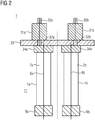
- Figure 2 shows a side view cut scheme of the three phase RC voltage divider 1 of figure 1 along the plane A.
- the three phase RC voltage divider 1 comprises a terminal cover plate 33, and three single phase RC voltage dividers 1a, 1b, 1c.
- FIG 2 only reference signs 1a, 1b are visible.
- the reference signs relating to the third single phase voltage divider 1c are also included in the following description.
- Each of the single phase RC voltage dividers 1a, 1b, 1c comprises a high voltage connection terminal 9a, 9b, 9c, an active part 8a, 8b, 8c, an inner compartment 7a, 7b, 7c, a connection flange 34a, 34b, 34c for ground connection, a secondary adjusting housing 31a, 31b, 31c, a bushing 32a, 32b, 32c between the active part 8a, 8b, 8c and the secondary adjusting housing 31a, 31b, 31c, and a secondary signal cable 30a, 30b, 30c.
- the RC voltage divider 1 does not comprise a resin barrier at the high voltage connection terminals 9a, 9b, 9c.
- the RC voltage divider of figure 1 is provided and tested, for example at the site of the RC voltage divider manufacturer.
- the RC voltage divider 1 is then transported to a gas insulated switchgear 3, for example at the premises of an electric power supplier.
- There the RC voltage divider 1 is mounted to the gas insulated switchgear 3, such that the terminal cover plate 33 of the voltage divider 1 and the a outer RC divider housing 19a, being part of a switchgear housing 19 or being mounted to a switchgear housing 19, are forming together a hermetically sealed common gas compartment 5.
- an insulating gas for example SF6, is filled into the common gas compartment 5. This way no resin barrier needs to be provided, and an embodiment of the arrangement 10 of figure 3 can be assembled more easily and overall cost can be reduced.
- Figure 3 shows the components of the three phase RC voltage divider 1 of figures 1 and 2 mounted together with the outer RC divider housing 19a being part of the switchgear housing 19 or being mounted to the switchgear housing 19.
- the RC voltage divider 1 is thus for example first provided without any outer RC divider housing 19a, e.g. at the premises of the voltage divider manufacturer. Only later, when the entire arrangement 10 is assembled, e.g. at a gas insulated switchgear site, the terminal cover plate 33 of the RC voltage divider 1 is mounted to the outer RC divider housing 19a of the gas insulated switchgear 3 in order to provide a common gas compartment 5.
- the high voltage connection terminals 9a, 9b, 9c of the RC voltage divider 1 are connected to GIS side connection terminals 6a, 6b, 6c of the GIS 3.
- the arrangement 10 comprises the gas insulated switchgear 3 and the RC voltage divider 1.
- the gas insulated switchgear 3 comprises a switchgear compartment 13, and the gas insulated switchgear housing 19, the RC voltage divider 1, and the voltage divider compartment 11.
- the GIS 3 and the RC voltage divider 1 are not hermetically sealed against each other.
- the single phase voltage dividers 1a, 1b, 1c each comprise a hermetically sealed inner compartment 7a, 7b, 7c filled with insulating oil or gas, and enclosing an active part of the respective single phase RC voltage divider 1a, 1b, 1c, such that the inner compartments are hermetically sealed.
- This allows to test each single phase voltage divider 1a, 1b, 1c, and to transport them as a pretested three phase RC voltage divider 1 to the site of the GIS, without a need to redo all tests at said site.
- the embodiments described on the basis of figure 3 show an arrangement where the three phase RC voltage divider 1 comprises three phases within one outer RC divider housing 19a being part of the gas insulated switchgear housing 19.
- another number of single phase voltage dividers can be packed into the outer RC divider housing 19a.
- the elimination of the resin barrier (closed support insulator) or the use of an open support insulator leads to the requirement for an encapsulated built up of the active part of the instrument transformers.
- the active parts of the RC Voltage Dividers are hermetical sealed in small FRP-tubes and therefore encapsulated from the GIS gas compartment.
- An advantage of an embodiment of the invention is the elimination of the support insulator.
- Another advantage is the simplifying of the overall housing of the GIS (cost reduction) by eliminating standard SF6-equipment (pressure control systems, burst pressure devices, humidity control systems and filling valves).
- Reduction of cost of the GIS is given by the possibility that the RC Voltage Divider can be delivered directly to the GIS-manufacturer without an outer hermetically sealed housing which includes also a support insulator and a transport cover for the support insulator.
- the RC Voltage Divider will be assembled directly to the housing of the GIS and finally tested together with the whole GIS.
Landscapes
- Engineering & Computer Science (AREA)
- Power Engineering (AREA)
- Manufacturing & Machinery (AREA)
- Gas-Insulated Switchgears (AREA)
- Patch Boards (AREA)
- Transformer Cooling (AREA)
- Feeding, Discharge, Calcimining, Fusing, And Gas-Generation Devices (AREA)
- Electron Tubes For Measurement (AREA)
- Electrostatic Separation (AREA)
- Transformers For Measuring Instruments (AREA)
Abstract
Description
- The invention relates to the technical field of arrangements for a gas insulated switchgear (GIS) and a RC voltage divider.
- To use a RC Voltage Divider in a common GIS gas compartment either the elimination of the resin barrier of the RC voltage divider (closed support insulator) or the use of an open support insulator is necessary.
- In order to deliver a pretested conventional gas insulated instrument transformer to the GIS manufacturer or on site, the active part must be assembled in a sealed and treated gas environment. Therefore all existing GIS instrument transformers need to be built in an own hermetical sealed and tested gas compartment.
- It is the objective of the present invention to simplify assembling and to reduce the overall cost of an arrangement that comprises a gas insulated switchgear and a RC voltage divider.
- This objective is solved by the measures taken in accordance with the independent claims. Further advantageous embodiments are proposed by the independent claims.
- According to an aspect, an arrangement comprising a gas insulated switchgear and an RC voltage divider is disclosed. The gas insulated switchgear comprises a switchgear compartment and a voltage divider compartment. The RC voltage divider and the gas insulated switchgear form together at least partially a hermetically sealed common gas compartment.
- According to a further aspect, a method for assembling an arrangement including a gas insulated switchgear and a RC voltage divider is disclosed. The gas insulated switchgear comprises a switchgear compartment. In a method step, a RC voltage divider that does not comprise a hermetically sealed outer RC divider housing and/or that does not comprise a resin barrier adjacent a high voltage connection terminal of the RC voltage divider is provided. In a further method step the RC voltage divider is tested. Then the RC voltage divider is mounted to the gas insulated switchgear, such that a gas insulated switchgear housing of the gas insulated switchgear and a terminal cover plate of the RC voltage divider form together at least partially a hermetically sealed common gas compartment.
- In the following the invention is described on the basis of embodiments illustrated by the figures.
-
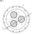
Figure 1 shows a top view scheme of a three phase RC voltage divider that can be used in an embodiment of the invention. -
Figure 2 shows a side view cut scheme of the three phase RC voltage divider offigure 1 . -
Figure 3 shows an assembly according to an embodiment of the invention. -
Figure 1 shows a top view of a threephase voltage divider 1, including three singlephase voltage dividers terminal cover plate 33. -
Figure 2 shows a side view cut scheme of the three phaseRC voltage divider 1 offigure 1 along the plane A. The three phaseRC voltage divider 1 comprises aterminal cover plate 33, and three single phaseRC voltage dividers figure 2 , onlyreference signs RC voltage dividers voltage connection terminal active part inner compartment connection flange secondary adjusting housing bushing active part housing secondary signal cable RC voltage divider 1 does not comprise a resin barrier at the highvoltage connection terminals - According to an embodiment, the RC voltage divider of
figure 1 is provided and tested, for example at the site of the RC voltage divider manufacturer. TheRC voltage divider 1 is then transported to a gas insulated switchgear 3, for example at the premises of an electric power supplier. There theRC voltage divider 1 is mounted to the gas insulated switchgear 3, such that theterminal cover plate 33 of thevoltage divider 1 and the a outerRC divider housing 19a, being part of aswitchgear housing 19 or being mounted to aswitchgear housing 19, are forming together a hermetically sealedcommon gas compartment 5. Then an insulating gas, for example SF6, is filled into thecommon gas compartment 5. This way no resin barrier needs to be provided, and an embodiment of thearrangement 10 offigure 3 can be assembled more easily and overall cost can be reduced. -
Figure 3 shows the components of the three phaseRC voltage divider 1 offigures 1 and2 mounted together with the outerRC divider housing 19a being part of theswitchgear housing 19 or being mounted to theswitchgear housing 19. According to this embodiment, theRC voltage divider 1 is thus for example first provided without any outerRC divider housing 19a, e.g. at the premises of the voltage divider manufacturer. Only later, when theentire arrangement 10 is assembled, e.g. at a gas insulated switchgear site, theterminal cover plate 33 of theRC voltage divider 1 is mounted to the outerRC divider housing 19a of the gas insulated switchgear 3 in order to provide acommon gas compartment 5. The highvoltage connection terminals RC voltage divider 1 are connected to GISside connection terminals - The
arrangement 10 comprises the gas insulated switchgear 3 and theRC voltage divider 1. The gas insulated switchgear 3 comprises aswitchgear compartment 13, and the gas insulatedswitchgear housing 19, theRC voltage divider 1, and thevoltage divider compartment 11. TheRC voltage divider 1 and the gas insulatedswitchgear housing 19, including the outerRC divider housing 19a, form together at least partially a hermetically sealedcommon gas compartment 5, such that gas within thecommon gas compartment 5 is allowed to be exchanged between theRC voltage divider 1 and thecommon gas compartment 5 of the gas insulatedswitchgear 10. In other words, the GIS 3 and theRC voltage divider 1 are not hermetically sealed against each other. - In the embodiments described on the basis of the figures, the single
phase voltage dividers inner compartment RC voltage divider phase voltage divider RC voltage divider 1 to the site of the GIS, without a need to redo all tests at said site. - The embodiments described on the basis of
figure 3 show an arrangement where the three phaseRC voltage divider 1 comprises three phases within one outerRC divider housing 19a being part of the gas insulatedswitchgear housing 19. Of course, also another number of single phase voltage dividers can be packed into the outerRC divider housing 19a. Particularly for very large voltages to be applied, in order to strongly insulate the phases from each other, it is advantageous to pack every single phase voltage divider into a separate outer RC divider housing. - In order to reduce overall costs of the GIS the requirement for an embodiment with just a pure RC Voltage Divider without separate SF6 filled housing including standard SF6-equipment (like pressure control systems, burst pressure devices, humidity control systems and filling valves) came up.
- According to an embodiment, the elimination of the resin barrier (closed support insulator) or the use of an open support insulator leads to the requirement for an encapsulated built up of the active part of the instrument transformers. The active parts of the RC Voltage Dividers are hermetical sealed in small FRP-tubes and therefore encapsulated from the GIS gas compartment.
- An advantage of an embodiment of the invention is the elimination of the support insulator. Another advantage is the simplifying of the overall housing of the GIS (cost reduction) by eliminating standard SF6-equipment (pressure control systems, burst pressure devices, humidity control systems and filling valves). Reduction of cost of the GIS is given by the possibility that the RC Voltage Divider can be delivered directly to the GIS-manufacturer without an outer hermetically sealed housing which includes also a support insulator and a transport cover for the support insulator. At GIS-manufacturer the RC Voltage Divider will be assembled directly to the housing of the GIS and finally tested together with the whole GIS.
- The pretesting, storing and shipping of the size reduced RC Voltage Dividers are simplified and therefore additional cost and time reduction results.
Claims (12)
- Arrangement (10), comprising a gas insulated switchgear (3) and a RC voltage divider (1), wherein the gas insulated switchgear (3) comprises a switchgear compartment (13) and a voltage divider compartment (11); and wherein
the RC voltage divider (1) and the gas insulated switchgear (3) form together at least partially a hermetically sealed common gas compartment (5). - The arrangement (10) of claim 1, wherein the arrangement (10) does not comprise a resin barrier hermetically separating the divider compartment (11) and the switchgear compartment (13).
- The arrangement (10) of any one of the preceding claims, wherein the voltage divider (1) comprises one phase or three phases.
- The arrangement (10) of any one of the preceding claims, wherein the RC voltage divider (1) comprises an inner compartment (7a, 7b, 7c) that is hermetically sealed against the divider compartment (11), wherein the inner compartment (7a, 7b, 7c) comprises an active part (8a, 8b, 8c) of the voltage divider (1).
- The arrangement (10) of claim 4, wherein the inner compartment (7) is filled with an insulating oil or an insulating gas.
- The arrangement (10) of any one of the preceding claims, wherein the common gas compartment (5) is filled with an insulating gas.
- Method for assembling an arrangement (10) including a gas insulated switchgear (3) and a RC voltage divider (1), wherein the gas insulated switchgear (3) comprises a switchgear compartment (13); the method comprising the steps of:(a) providing a RC voltage divider (1) that does not comprise a hermetically sealed outer RC divider housing (19a) and/or that does not comprise a resin barrier adjacent a high voltage connection terminal (9a, 9b, 9c) of the RC voltage divider (1);(b) testing the RC voltage divider (1);(c) mounting the RC voltage divider (1) to the gas insulated switchgear (3), such that a gas insulated switchgear housing (19) and a terminal cover plate (33) of the RC voltage divider (1) form together at least partially a hermetically sealed common gas compartment (5).
- The method of claim 7, wherein the method step (a) comprises providing the RC voltage divider (1) without a divider compartment (11), and wherein step (c) comprises mounting an outer RC divider housing (19a) to the gas insulated switchgear (3) in order to provide the divider compartment (11).
- The method of any one of claims 7 or 8, wherein the RC voltage divider (1) comprises one phase or three phases.
- The method of any one of claims 7 to 9, wherein the method step (a) comprises providing the RC voltage divider (1) with a hermetically sealed inner compartment (7a, 7b, 7c) enclosing an active part (8a, 8b, 8c) of the RC voltage divider (1).
- The method of claim 10, wherein method step (a) of providing the RC voltage divider comprises filling the inner compartment (7) with an insulating oil or an insulating gas.
- The method of any one of claims 7 to 11, wherein method step (c) comprises filling an insulating gas into the common gas compartment (5).
Priority Applications (9)
| Application Number | Priority Date | Filing Date | Title |
|---|---|---|---|
| EP14184299.7A EP2996213B1 (en) | 2014-09-10 | 2014-09-10 | RC Voltage Dividers used in common GIS gas compartment |
| ES14184299T ES2819188T3 (en) | 2014-09-10 | 2014-09-10 | RC voltage dividers used in a common GIS gas compartment |
| CN201580048331.5A CN106688153B (en) | 2014-09-10 | 2015-07-15 | Apparatus including gas insulated switchgear and RC voltage divider and method of assembling the same |
| RU2017111350A RU2674475C2 (en) | 2014-09-10 | 2015-07-15 | Rc voltage dividers used in general gas-insulated switch chamber |
| CA2960533A CA2960533C (en) | 2014-09-10 | 2015-07-15 | Rc voltage dividers used in common gis gas compartment |
| US15/510,349 US10103523B2 (en) | 2014-09-10 | 2015-07-15 | RC voltage dividers used in common GIS gas compartment |
| PCT/EP2015/066166 WO2016037742A1 (en) | 2014-09-10 | 2015-07-15 | Rc voltage dividers used in common gis gas compartment |
| BR112017003801A BR112017003801B8 (en) | 2014-09-10 | 2015-07-15 | ARRANGEMENT COMPRISING A GAS-INSULATED SWITCHBOARD AND AN RC VOLTAGE DIVIDER AND METHOD FOR ASSEMBLING AN ARRANGEMENT |
| HRP20201456TT HRP20201456T1 (en) | 2014-09-10 | 2020-09-11 | Rc voltage dividers used in common gis gas compartment |
Applications Claiming Priority (1)
| Application Number | Priority Date | Filing Date | Title |
|---|---|---|---|
| EP14184299.7A EP2996213B1 (en) | 2014-09-10 | 2014-09-10 | RC Voltage Dividers used in common GIS gas compartment |
Publications (2)
| Publication Number | Publication Date |
|---|---|
| EP2996213A1 true EP2996213A1 (en) | 2016-03-16 |
| EP2996213B1 EP2996213B1 (en) | 2020-08-05 |
Family
ID=51518637
Family Applications (1)
| Application Number | Title | Priority Date | Filing Date |
|---|---|---|---|
| EP14184299.7A Active EP2996213B1 (en) | 2014-09-10 | 2014-09-10 | RC Voltage Dividers used in common GIS gas compartment |
Country Status (9)
| Country | Link |
|---|---|
| US (1) | US10103523B2 (en) |
| EP (1) | EP2996213B1 (en) |
| CN (1) | CN106688153B (en) |
| BR (1) | BR112017003801B8 (en) |
| CA (1) | CA2960533C (en) |
| ES (1) | ES2819188T3 (en) |
| HR (1) | HRP20201456T1 (en) |
| RU (1) | RU2674475C2 (en) |
| WO (1) | WO2016037742A1 (en) |
Citations (3)
| Publication number | Priority date | Publication date | Assignee | Title |
|---|---|---|---|---|
| JPS5346060A (en) * | 1976-10-07 | 1978-04-25 | Toshiba Corp | Voltage divider for high voltage measurement |
| JPS5575654A (en) * | 1978-12-01 | 1980-06-07 | Mitsubishi Electric Corp | Voltage divider |
| FR2651889A1 (en) * | 1989-09-08 | 1991-03-15 | Alsthom Gec | Electronic capacitive voltage reducer |
Family Cites Families (15)
| Publication number | Priority date | Publication date | Assignee | Title |
|---|---|---|---|---|
| SU539544A3 (en) * | 1971-10-26 | 1976-12-15 | Фудзи Денки Сейзо Кабусики Кайся (Фирма) | Synchronous switch |
| DE2234055A1 (en) * | 1972-07-11 | 1974-01-24 | Siemens Ag | IGNITION VOLTAGE GENERATOR |
| US4034283A (en) * | 1975-08-28 | 1977-07-05 | The Machlett Laboratories, Incorporated | Compensated voltage divider |
| FR2328968A1 (en) * | 1975-10-23 | 1977-05-20 | Merlin Gerin | HV measuring system for multiphase installations - uses capacitively coupled voltage divider formed by coaxial electrodes in chambers screening out stray capacitance |
| JPS5257671U (en) * | 1975-10-23 | 1977-04-26 | ||
| JPS5736733A (en) * | 1980-08-14 | 1982-02-27 | Tokyo Shibaura Electric Co | |
| CA1325234C (en) * | 1988-03-28 | 1993-12-14 | Minori Sato | Circuit breaker |
| ATE93326T1 (en) * | 1989-03-22 | 1993-09-15 | Siemens Ag | MEASURING DEVICE WITH AN AUXILIARY ELECTRODE FOR A GAS-INSULATED, ENCLOSED HIGH-VOLTAGE SYSTEM. |
| FR2649245B1 (en) * | 1989-06-29 | 1994-02-25 | Gec Alsthom Sa | HIGH VOLTAGE CIRCUIT BREAKER WITH BUILT-IN VOLTAGE DETECTION DEVICES |
| FR2674984B1 (en) * | 1991-04-05 | 1993-06-11 | Alsthom Gec | SF6 CIRCUIT BREAKER WITH INCORPORATED CAPACITOR. |
| FR2770696B1 (en) * | 1997-11-06 | 1999-12-31 | Gec Alsthom T & D Sa | ELECTRICAL LINE WITH GAS INSULATION AND INCORPORATED POWER CAPACITOR |
| JP2003511704A (en) * | 1999-10-12 | 2003-03-25 | シーメンス アクチエンゲゼルシヤフト | Sensor for detecting high-frequency voltage oscillation and sensor arrangement |
| US7079004B2 (en) * | 2003-10-10 | 2006-07-18 | Agilent Technologies, Inc. | Precision thin film AC voltage divider |
| CN201829857U (en) * | 2010-11-01 | 2011-05-11 | 广东电网公司茂名供电局 | HGIS (Hybrid Gas Insulated Switchgear) high-voltage electrical apparatus combined with electronic mutual inductor |
| CN202119836U (en) * | 2011-05-12 | 2012-01-18 | 山东泰开高压开关有限公司 | Device for primary phase acquisition of GIS |
-
2014
- 2014-09-10 ES ES14184299T patent/ES2819188T3/en active Active
- 2014-09-10 EP EP14184299.7A patent/EP2996213B1/en active Active
-
2015
- 2015-07-15 WO PCT/EP2015/066166 patent/WO2016037742A1/en not_active Ceased
- 2015-07-15 CN CN201580048331.5A patent/CN106688153B/en active Active
- 2015-07-15 BR BR112017003801A patent/BR112017003801B8/en active IP Right Grant
- 2015-07-15 RU RU2017111350A patent/RU2674475C2/en active
- 2015-07-15 US US15/510,349 patent/US10103523B2/en active Active
- 2015-07-15 CA CA2960533A patent/CA2960533C/en active Active
-
2020
- 2020-09-11 HR HRP20201456TT patent/HRP20201456T1/en unknown
Patent Citations (3)
| Publication number | Priority date | Publication date | Assignee | Title |
|---|---|---|---|---|
| JPS5346060A (en) * | 1976-10-07 | 1978-04-25 | Toshiba Corp | Voltage divider for high voltage measurement |
| JPS5575654A (en) * | 1978-12-01 | 1980-06-07 | Mitsubishi Electric Corp | Voltage divider |
| FR2651889A1 (en) * | 1989-09-08 | 1991-03-15 | Alsthom Gec | Electronic capacitive voltage reducer |
Also Published As
| Publication number | Publication date |
|---|---|
| BR112017003801B8 (en) | 2023-04-25 |
| ES2819188T3 (en) | 2021-04-15 |
| CN106688153A (en) | 2017-05-17 |
| RU2017111350A (en) | 2018-10-10 |
| RU2017111350A3 (en) | 2018-10-10 |
| EP2996213B1 (en) | 2020-08-05 |
| BR112017003801A2 (en) | 2017-11-28 |
| CA2960533A1 (en) | 2016-03-17 |
| RU2674475C2 (en) | 2018-12-11 |
| US20170256924A1 (en) | 2017-09-07 |
| CA2960533C (en) | 2019-08-06 |
| WO2016037742A1 (en) | 2016-03-17 |
| HRP20201456T1 (en) | 2020-12-25 |
| US10103523B2 (en) | 2018-10-16 |
| CN106688153B (en) | 2019-06-04 |
| BR112017003801B1 (en) | 2022-09-06 |
Similar Documents
| Publication | Publication Date | Title |
|---|---|---|
| US10262791B2 (en) | Arrangement of single phase transformers | |
| EP3559963B1 (en) | Combined instrument transformer for hv applications. | |
| US20130250487A1 (en) | Switch bay for high-voltage switchgear assembly, and method for installation thereof | |
| US10514395B2 (en) | Method and system for insulating an RC voltage divider with an active part in oil and an outer part in gas | |
| KR101263411B1 (en) | Gas-insulated high-voltage measuring unit | |
| US9058926B2 (en) | Fluid insulated high voltage coil | |
| EP2996213B1 (en) | RC Voltage Dividers used in common GIS gas compartment | |
| WO2015166545A1 (en) | Gas-insulated switchgear | |
| JP4764139B2 (en) | Connection structure of gas insulated switchgear and oil-filled transformer | |
| CN204793699U (en) | GIS terminal box and GIS terminal box subassembly | |
| US10818434B2 (en) | Adaptor for a capacitor | |
| JP3203676U (en) | Gas insulated switchgear | |
| JP6190442B2 (en) | Gas insulated switchgear | |
| EP2570817A1 (en) | Optical current transformer for gas-insulated apparatus | |
| EP3391397B1 (en) | Current transformer for high voltage gas insulated switchgear substation | |
| JP2012231576A (en) | Gas insulated switchgear | |
| US20160134086A1 (en) | Gas-insulated medium-voltage switchgear assembly | |
| US9859178B2 (en) | Packaging for high-power microwave module | |
| JP2007158041A (en) | Arresta | |
| JP2017143637A (en) | Switchgear and switchgear assembling method |
Legal Events
| Date | Code | Title | Description |
|---|---|---|---|
| PUAI | Public reference made under article 153(3) epc to a published international application that has entered the european phase |
Free format text: ORIGINAL CODE: 0009012 |
|
| AK | Designated contracting states |
Kind code of ref document: A1 Designated state(s): AL AT BE BG CH CY CZ DE DK EE ES FI FR GB GR HR HU IE IS IT LI LT LU LV MC MK MT NL NO PL PT RO RS SE SI SK SM TR |
|
| AX | Request for extension of the european patent |
Extension state: BA ME |
|
| 17P | Request for examination filed |
Effective date: 20160819 |
|
| RBV | Designated contracting states (corrected) |
Designated state(s): AL AT BE BG CH CY CZ DE DK EE ES FI FR GB GR HR HU IE IS IT LI LT LU LV MC MK MT NL NO PL PT RO RS SE SI SK SM TR |
|
| RAP1 | Party data changed (applicant data changed or rights of an application transferred) |
Owner name: SIEMENS AKTIENGESELLSCHAFT |
|
| STAA | Information on the status of an ep patent application or granted ep patent |
Free format text: STATUS: EXAMINATION IS IN PROGRESS |
|
| 17Q | First examination report despatched |
Effective date: 20180925 |
|
| 17Q | First examination report despatched |
Effective date: 20181010 |
|
| GRAP | Despatch of communication of intention to grant a patent |
Free format text: ORIGINAL CODE: EPIDOSNIGR1 |
|
| STAA | Information on the status of an ep patent application or granted ep patent |
Free format text: STATUS: GRANT OF PATENT IS INTENDED |
|
| INTG | Intention to grant announced |
Effective date: 20200428 |
|
| GRAS | Grant fee paid |
Free format text: ORIGINAL CODE: EPIDOSNIGR3 |
|
| GRAA | (expected) grant |
Free format text: ORIGINAL CODE: 0009210 |
|
| STAA | Information on the status of an ep patent application or granted ep patent |
Free format text: STATUS: THE PATENT HAS BEEN GRANTED |
|
| AK | Designated contracting states |
Kind code of ref document: B1 Designated state(s): AL AT BE BG CH CY CZ DE DK EE ES FI FR GB GR HR HU IE IS IT LI LT LU LV MC MK MT NL NO PL PT RO RS SE SI SK SM TR |
|
| REG | Reference to a national code |
Ref country code: GB Ref legal event code: FG4D |
|
| REG | Reference to a national code |
Ref country code: CH Ref legal event code: EP |
|
| REG | Reference to a national code |
Ref country code: AT Ref legal event code: REF Ref document number: 1300061 Country of ref document: AT Kind code of ref document: T Effective date: 20200815 |
|
| REG | Reference to a national code |
Ref country code: DE Ref legal event code: R096 Ref document number: 602014068501 Country of ref document: DE |
|
| REG | Reference to a national code |
Ref country code: IE Ref legal event code: FG4D |
|
| REG | Reference to a national code |
Ref country code: HR Ref legal event code: TUEP Ref document number: P20201456 Country of ref document: HR |
|
| REG | Reference to a national code |
Ref country code: CH Ref legal event code: NV Representative=s name: SIEMENS SCHWEIZ AG, CH |
|
| REG | Reference to a national code |
Ref country code: SE Ref legal event code: TRGR |
|
| REG | Reference to a national code |
Ref country code: HR Ref legal event code: ODRP Ref document number: P20201456 Country of ref document: HR Payment date: 20200914 Year of fee payment: 7 |
|
| REG | Reference to a national code |
Ref country code: DE Ref legal event code: R081 Ref document number: 602014068501 Country of ref document: DE Owner name: HSP HOCHSPANNUNGSGERAETE GMBH, DE Free format text: FORMER OWNER: SIEMENS AKTIENGESELLSCHAFT, 80333 MUENCHEN, DE Ref country code: DE Ref legal event code: R081 Ref document number: 602014068501 Country of ref document: DE Owner name: SIEMENS ENERGY GLOBAL GMBH & CO. KG, DE Free format text: FORMER OWNER: SIEMENS AKTIENGESELLSCHAFT, 80333 MUENCHEN, DE |
|
| REG | Reference to a national code |
Ref country code: HR Ref legal event code: T1PR Ref document number: P20201456 Country of ref document: HR |
|
| REG | Reference to a national code |
Ref country code: LT Ref legal event code: MG4D |
|
| REG | Reference to a national code |
Ref country code: NL Ref legal event code: MP Effective date: 20200805 |
|
| REG | Reference to a national code |
Ref country code: AT Ref legal event code: MK05 Ref document number: 1300061 Country of ref document: AT Kind code of ref document: T Effective date: 20200805 |
|
| RAP2 | Party data changed (patent owner data changed or rights of a patent transferred) |
Owner name: SIEMENS ENERGY GLOBAL GMBH & CO. KG |
|
| PG25 | Lapsed in a contracting state [announced via postgrant information from national office to epo] |
Ref country code: AT Free format text: LAPSE BECAUSE OF FAILURE TO SUBMIT A TRANSLATION OF THE DESCRIPTION OR TO PAY THE FEE WITHIN THE PRESCRIBED TIME-LIMIT Effective date: 20200805 Ref country code: GR Free format text: LAPSE BECAUSE OF FAILURE TO SUBMIT A TRANSLATION OF THE DESCRIPTION OR TO PAY THE FEE WITHIN THE PRESCRIBED TIME-LIMIT Effective date: 20201106 Ref country code: PT Free format text: LAPSE BECAUSE OF FAILURE TO SUBMIT A TRANSLATION OF THE DESCRIPTION OR TO PAY THE FEE WITHIN THE PRESCRIBED TIME-LIMIT Effective date: 20201207 Ref country code: NO Free format text: LAPSE BECAUSE OF FAILURE TO SUBMIT A TRANSLATION OF THE DESCRIPTION OR TO PAY THE FEE WITHIN THE PRESCRIBED TIME-LIMIT Effective date: 20201105 Ref country code: LT Free format text: LAPSE BECAUSE OF FAILURE TO SUBMIT A TRANSLATION OF THE DESCRIPTION OR TO PAY THE FEE WITHIN THE PRESCRIBED TIME-LIMIT Effective date: 20200805 Ref country code: FI Free format text: LAPSE BECAUSE OF FAILURE TO SUBMIT A TRANSLATION OF THE DESCRIPTION OR TO PAY THE FEE WITHIN THE PRESCRIBED TIME-LIMIT Effective date: 20200805 |
|
| PG25 | Lapsed in a contracting state [announced via postgrant information from national office to epo] |
Ref country code: IS Free format text: LAPSE BECAUSE OF FAILURE TO SUBMIT A TRANSLATION OF THE DESCRIPTION OR TO PAY THE FEE WITHIN THE PRESCRIBED TIME-LIMIT Effective date: 20201205 Ref country code: RS Free format text: LAPSE BECAUSE OF FAILURE TO SUBMIT A TRANSLATION OF THE DESCRIPTION OR TO PAY THE FEE WITHIN THE PRESCRIBED TIME-LIMIT Effective date: 20200805 Ref country code: LV Free format text: LAPSE BECAUSE OF FAILURE TO SUBMIT A TRANSLATION OF THE DESCRIPTION OR TO PAY THE FEE WITHIN THE PRESCRIBED TIME-LIMIT Effective date: 20200805 Ref country code: NL Free format text: LAPSE BECAUSE OF FAILURE TO SUBMIT A TRANSLATION OF THE DESCRIPTION OR TO PAY THE FEE WITHIN THE PRESCRIBED TIME-LIMIT Effective date: 20200805 Ref country code: PL Free format text: LAPSE BECAUSE OF FAILURE TO SUBMIT A TRANSLATION OF THE DESCRIPTION OR TO PAY THE FEE WITHIN THE PRESCRIBED TIME-LIMIT Effective date: 20200805 |
|
| REG | Reference to a national code |
Ref country code: ES Ref legal event code: FG2A Ref document number: 2819188 Country of ref document: ES Kind code of ref document: T3 Effective date: 20210415 |
|
| PG25 | Lapsed in a contracting state [announced via postgrant information from national office to epo] |
Ref country code: EE Free format text: LAPSE BECAUSE OF FAILURE TO SUBMIT A TRANSLATION OF THE DESCRIPTION OR TO PAY THE FEE WITHIN THE PRESCRIBED TIME-LIMIT Effective date: 20200805 Ref country code: DK Free format text: LAPSE BECAUSE OF FAILURE TO SUBMIT A TRANSLATION OF THE DESCRIPTION OR TO PAY THE FEE WITHIN THE PRESCRIBED TIME-LIMIT Effective date: 20200805 Ref country code: SM Free format text: LAPSE BECAUSE OF FAILURE TO SUBMIT A TRANSLATION OF THE DESCRIPTION OR TO PAY THE FEE WITHIN THE PRESCRIBED TIME-LIMIT Effective date: 20200805 Ref country code: RO Free format text: LAPSE BECAUSE OF FAILURE TO SUBMIT A TRANSLATION OF THE DESCRIPTION OR TO PAY THE FEE WITHIN THE PRESCRIBED TIME-LIMIT Effective date: 20200805 |
|
| REG | Reference to a national code |
Ref country code: DE Ref legal event code: R097 Ref document number: 602014068501 Country of ref document: DE |
|
| PG25 | Lapsed in a contracting state [announced via postgrant information from national office to epo] |
Ref country code: MC Free format text: LAPSE BECAUSE OF FAILURE TO SUBMIT A TRANSLATION OF THE DESCRIPTION OR TO PAY THE FEE WITHIN THE PRESCRIBED TIME-LIMIT Effective date: 20200805 Ref country code: AL Free format text: LAPSE BECAUSE OF FAILURE TO SUBMIT A TRANSLATION OF THE DESCRIPTION OR TO PAY THE FEE WITHIN THE PRESCRIBED TIME-LIMIT Effective date: 20200805 |
|
| PLBE | No opposition filed within time limit |
Free format text: ORIGINAL CODE: 0009261 |
|
| STAA | Information on the status of an ep patent application or granted ep patent |
Free format text: STATUS: NO OPPOSITION FILED WITHIN TIME LIMIT |
|
| REG | Reference to a national code |
Ref country code: BE Ref legal event code: MM Effective date: 20200930 |
|
| PG25 | Lapsed in a contracting state [announced via postgrant information from national office to epo] |
Ref country code: LU Free format text: LAPSE BECAUSE OF NON-PAYMENT OF DUE FEES Effective date: 20200910 Ref country code: SK Free format text: LAPSE BECAUSE OF FAILURE TO SUBMIT A TRANSLATION OF THE DESCRIPTION OR TO PAY THE FEE WITHIN THE PRESCRIBED TIME-LIMIT Effective date: 20200805 |
|
| 26N | No opposition filed |
Effective date: 20210507 |
|
| GBPC | Gb: european patent ceased through non-payment of renewal fee |
Effective date: 20201105 |
|
| PG25 | Lapsed in a contracting state [announced via postgrant information from national office to epo] |
Ref country code: BE Free format text: LAPSE BECAUSE OF NON-PAYMENT OF DUE FEES Effective date: 20200930 Ref country code: SI Free format text: LAPSE BECAUSE OF FAILURE TO SUBMIT A TRANSLATION OF THE DESCRIPTION OR TO PAY THE FEE WITHIN THE PRESCRIBED TIME-LIMIT Effective date: 20200805 Ref country code: IE Free format text: LAPSE BECAUSE OF NON-PAYMENT OF DUE FEES Effective date: 20200910 |
|
| REG | Reference to a national code |
Ref country code: HR Ref legal event code: ODRP Ref document number: P20201456 Country of ref document: HR Payment date: 20210906 Year of fee payment: 8 |
|
| PG25 | Lapsed in a contracting state [announced via postgrant information from national office to epo] |
Ref country code: GB Free format text: LAPSE BECAUSE OF NON-PAYMENT OF DUE FEES Effective date: 20201105 |
|
| PG25 | Lapsed in a contracting state [announced via postgrant information from national office to epo] |
Ref country code: IS Free format text: LAPSE BECAUSE OF FAILURE TO SUBMIT A TRANSLATION OF THE DESCRIPTION OR TO PAY THE FEE WITHIN THE PRESCRIBED TIME-LIMIT Effective date: 20201205 Ref country code: MT Free format text: LAPSE BECAUSE OF FAILURE TO SUBMIT A TRANSLATION OF THE DESCRIPTION OR TO PAY THE FEE WITHIN THE PRESCRIBED TIME-LIMIT Effective date: 20200805 Ref country code: CY Free format text: LAPSE BECAUSE OF FAILURE TO SUBMIT A TRANSLATION OF THE DESCRIPTION OR TO PAY THE FEE WITHIN THE PRESCRIBED TIME-LIMIT Effective date: 20200805 |
|
| PG25 | Lapsed in a contracting state [announced via postgrant information from national office to epo] |
Ref country code: MK Free format text: LAPSE BECAUSE OF FAILURE TO SUBMIT A TRANSLATION OF THE DESCRIPTION OR TO PAY THE FEE WITHIN THE PRESCRIBED TIME-LIMIT Effective date: 20200805 |
|
| REG | Reference to a national code |
Ref country code: HR Ref legal event code: ODRP Ref document number: P20201456 Country of ref document: HR Payment date: 20220906 Year of fee payment: 9 |
|
| REG | Reference to a national code |
Ref country code: HR Ref legal event code: PPPP Ref document number: P20201456 Country of ref document: HR Owner name: SIEMENS ENERGY GLOBAL GMBH & CO. KG, DE |
|
| REG | Reference to a national code |
Ref country code: HR Ref legal event code: ODRP Ref document number: P20201456 Country of ref document: HR Payment date: 20230823 Year of fee payment: 10 |
|
| REG | Reference to a national code |
Ref country code: HR Ref legal event code: PPPP Ref document number: P20201456 Country of ref document: HR Owner name: HSP HOCHSPANNUNGSGERAETE GMBH, DE |
|
| REG | Reference to a national code |
Ref country code: DE Ref legal event code: R081 Ref document number: 602014068501 Country of ref document: DE Owner name: HSP HOCHSPANNUNGSGERAETE GMBH, DE Free format text: FORMER OWNER: SIEMENS ENERGY GLOBAL GMBH & CO. KG, 81739 MUENCHEN, DE |
|
| REG | Reference to a national code |
Ref country code: HR Ref legal event code: ODRP Ref document number: P20201456 Country of ref document: HR Payment date: 20240821 Year of fee payment: 11 |
|
| REG | Reference to a national code |
Ref country code: ES Ref legal event code: PC2A Owner name: HSP HOCHSPANNUNGSGERAETE GMBH Effective date: 20250206 |
|
| REG | Reference to a national code |
Ref country code: HR Ref legal event code: ODRP Ref document number: P20201456 Country of ref document: HR Payment date: 20250903 Year of fee payment: 12 |
|
| REG | Reference to a national code |
Ref country code: CH Ref legal event code: U11 Free format text: ST27 STATUS EVENT CODE: U-0-0-U10-U11 (AS PROVIDED BY THE NATIONAL OFFICE) Effective date: 20251001 |
|
| PGFP | Annual fee paid to national office [announced via postgrant information from national office to epo] |
Ref country code: DE Payment date: 20250929 Year of fee payment: 12 |
|
| PGFP | Annual fee paid to national office [announced via postgrant information from national office to epo] |
Ref country code: TR Payment date: 20250822 Year of fee payment: 12 Ref country code: IT Payment date: 20250919 Year of fee payment: 12 |
|
| PGFP | Annual fee paid to national office [announced via postgrant information from national office to epo] |
Ref country code: BG Payment date: 20250917 Year of fee payment: 12 |
|
| PGFP | Annual fee paid to national office [announced via postgrant information from national office to epo] |
Ref country code: HR Payment date: 20250903 Year of fee payment: 12 |
|
| PGFP | Annual fee paid to national office [announced via postgrant information from national office to epo] |
Ref country code: FR Payment date: 20250925 Year of fee payment: 12 |
|
| PGFP | Annual fee paid to national office [announced via postgrant information from national office to epo] |
Ref country code: SE Payment date: 20250927 Year of fee payment: 12 |
|
| PGFP | Annual fee paid to national office [announced via postgrant information from national office to epo] |
Ref country code: CZ Payment date: 20250826 Year of fee payment: 12 |
|
| PGFP | Annual fee paid to national office [announced via postgrant information from national office to epo] |
Ref country code: CH Payment date: 20251001 Year of fee payment: 12 |
|
| PGFP | Annual fee paid to national office [announced via postgrant information from national office to epo] |
Ref country code: ES Payment date: 20251001 Year of fee payment: 12 |