EP2996207A1 - Connector - Google Patents
Connector Download PDFInfo
- Publication number
- EP2996207A1 EP2996207A1 EP13884360.2A EP13884360A EP2996207A1 EP 2996207 A1 EP2996207 A1 EP 2996207A1 EP 13884360 A EP13884360 A EP 13884360A EP 2996207 A1 EP2996207 A1 EP 2996207A1
- Authority
- EP
- European Patent Office
- Prior art keywords
- slider
- position holding
- connection position
- housing
- initial position
- Prior art date
- Legal status (The legal status is an assumption and is not a legal conclusion. Google has not performed a legal analysis and makes no representation as to the accuracy of the status listed.)
- Withdrawn
Links
- 230000008878 coupling Effects 0.000 claims abstract description 25
- 238000010168 coupling process Methods 0.000 claims abstract description 25
- 238000005859 coupling reaction Methods 0.000 claims abstract description 25
- 238000000034 method Methods 0.000 description 11
- 230000001105 regulatory effect Effects 0.000 description 6
- 230000002093 peripheral effect Effects 0.000 description 5
- 229920003002 synthetic resin Polymers 0.000 description 3
- 239000000057 synthetic resin Substances 0.000 description 3
- 230000000717 retained effect Effects 0.000 description 2
- 230000004308 accommodation Effects 0.000 description 1
- 230000006835 compression Effects 0.000 description 1
- 238000007906 compression Methods 0.000 description 1
- 239000004020 conductor Substances 0.000 description 1
- 238000006073 displacement reaction Methods 0.000 description 1
- 230000000694 effects Effects 0.000 description 1
- 238000003780 insertion Methods 0.000 description 1
- 230000037431 insertion Effects 0.000 description 1
- 238000012423 maintenance Methods 0.000 description 1
- 238000007789 sealing Methods 0.000 description 1
Images


Classifications
-
- H—ELECTRICITY
- H01—ELECTRIC ELEMENTS
- H01R—ELECTRICALLY-CONDUCTIVE CONNECTIONS; STRUCTURAL ASSOCIATIONS OF A PLURALITY OF MUTUALLY-INSULATED ELECTRICAL CONNECTING ELEMENTS; COUPLING DEVICES; CURRENT COLLECTORS
- H01R13/00—Details of coupling devices of the kinds covered by groups H01R12/70 or H01R24/00 - H01R33/00
- H01R13/62—Means for facilitating engagement or disengagement of coupling parts or for holding them in engagement
- H01R13/627—Snap or like fastening
- H01R13/6271—Latching means integral with the housing
- H01R13/6272—Latching means integral with the housing comprising a single latching arm
-
- H—ELECTRICITY
- H01—ELECTRIC ELEMENTS
- H01R—ELECTRICALLY-CONDUCTIVE CONNECTIONS; STRUCTURAL ASSOCIATIONS OF A PLURALITY OF MUTUALLY-INSULATED ELECTRICAL CONNECTING ELEMENTS; COUPLING DEVICES; CURRENT COLLECTORS
- H01R13/00—Details of coupling devices of the kinds covered by groups H01R12/70 or H01R24/00 - H01R33/00
- H01R13/64—Means for preventing incorrect coupling
- H01R13/641—Means for preventing incorrect coupling by indicating incorrect coupling; by indicating correct or full engagement
-
- H—ELECTRICITY
- H01—ELECTRIC ELEMENTS
- H01R—ELECTRICALLY-CONDUCTIVE CONNECTIONS; STRUCTURAL ASSOCIATIONS OF A PLURALITY OF MUTUALLY-INSULATED ELECTRICAL CONNECTING ELEMENTS; COUPLING DEVICES; CURRENT COLLECTORS
- H01R13/00—Details of coupling devices of the kinds covered by groups H01R12/70 or H01R24/00 - H01R33/00
- H01R13/62—Means for facilitating engagement or disengagement of coupling parts or for holding them in engagement
- H01R13/639—Additional means for holding or locking coupling parts together, after engagement, e.g. separate keylock, retainer strap
Definitions
- the present invention relates to a connector.
- a connector disclosed in patent literature 1 includes first and second housings connectable to each other (called “male and female connectors” in patent literature 1) and a slider (called a “front slider and a rear slider” in patent literature 1) movably assembled with the first housing.
- a coil spring is incorporated into the slider.
- the first housing includes a tubular receptacle into which the second housing is fittable, and an accommodating chamber capable of accommodating the slider is provided on a ceiling part of the receptacle.
- an accommodating chamber capable of accommodating the slider is provided on a ceiling part of the receptacle.
- Patent literature 1 is a patent literature 1
- the ceiling wall is arranged to cover the slider from above, there is a problem of increasing a height of the connector by a thickness of the ceiling wall.
- the holding receiving portion is also eliminated if the ceiling wall is merely omitted, wherefore a detachment of the slider cannot be prevented. This is an unfavorable situation.
- the present invention was completed based on the above situation and aims to prevent a detachment of a slider while avoiding the enlargement of a connector.
- the present invention is directed to a connector with a second housing including a lock portion, a first housing connectable to the second housing, and a slider assembled with the first housing movably between an initial position and a connection position and configured to be moved from the initial position to the connection position as the first and second housings are properly connected
- the first housing includes a housing main body configured such that the second housing is externally fittable thereon and a lock arm configured to form a deflection space between the lock arm and the housing main body and hold the first and second housings in a connected state by resiliently locking the lock portion
- the lock arm includes a connection position holding receiving portion on a surface on a side opposite to a surface facing the housing main body
- the housing main body includes an initial position holding receiving portion on a surface facing the lock arm
- the slider includes a base portion extending along a width direction and to be inserted into the deflection space, a pair of arm portions projecting from opposite widthwise end parts of the base portion and a coupling portion coupling projecting end parts of the
- connection position holding portion provided on the coupling portion of the slider comes into contact with the connection position holding receiving portion of the lock arm to regulate a detachment of the slider. Further, when the slider is at the initial position, the initial position holding portion provided on the base portion of the slider resiliently locks the initial position holding receiving portion of the housing main body to regulate an inadvertent movement of the slider to the connection position.
- connection position holding receiving portion is not provided on a ceiling wall covering the slider in the above case, the ceiling wall can be omitted from the connector. Further, since the base portion is inserted into the deflection space, which is a dead space between the lock arm and the housing main body, it is not necessary to provide the connector with a dedicated insertion space for the base portion. Thus, the enlargement of the connector can be avoided.
- the first housing includes a pair of guide walls located at opposite widthwise sides of the lock arm and the both arm portions slide on the both guide walls to guide a movement of the slider. Since the movement of the slider is guided by the both arm portions connecting the coupling portion and the base portion, it is not necessary to provide the slider with a dedicated guide structure for guiding a movement and the configuration of the slider can be simplified.
- the slider is formed into a frame shape as a whole by the base portion, the both arm portions and the coupling portion, and the initial position holding portion projects into a frame defined by the slider. Since the entire slider is formed into the frame shape, the slider is structured to be excellent in shape stability. Further, since the initial position holding portion projects into the frame defined by the slider, the surrounding of the initial position holding portion is protected and a situation where the initial position holding portion is broken or fractured by interference with an external matter can be avoided.
- connection position holding receiving portion projects on a main body part of the lock arm, and the connection position holding portion is provided by recessing the coupling portion so that the connection position holding receiving portion is insertable thereinto. This prevents a contact state of the connection position holding portion and the connection position holding receiving portion from being inadvertently released at the connection position.
- FIGS. 1 to 12 One embodiment of the present invention is described with reference to FIGS. 1 to 12 .
- This embodiment includes first and second housings 10, 90 connectable to each other, a slider 60 to be assembled with the first housing 10, spring members 80 to be assembled with the slider 60, first terminal fittings 20 to be mounted into the first housing 10 and second terminal fittings 99 to be mounted into the second housing 90.
- connection surface sides of the first and second housings 10, 90 are referred to as front sides concerning a front-back direction and a vertical direction is based on FIG. 3 .
- the second housing 90 is made of synthetic resin and includes, as shown in FIG. 3 , a tubular receptacle 91. Tabs 95 of the second terminal fittings 99 are arranged to project into the receptacle 91. A lock portion 92 is provided to project on the upper surface of the upper wall of the receptacle 91. Further, as shown in FIG. 1 , a pair of guide projections 93 are formed to extend in the front-back direction at opposite widthwise sides of the lock portion 92 on the upper surface of the upper wall of the receptacle 91 and, further, a pair of pressing portions 94 are formed to extend in the front-back direction at opposite outer sides of the both guide projections 93. As shown in FIG. 4 , a releasing portion 96 capable of releasing locking between an initial position holding portion 76 and an initial position holding receiving portion 25 to be described later is formed on the opening edge of the front end of the upper wall of the receptacle 91.
- the first housing 10 is likewise made of synthetic resin and includes, as shown in FIGS. 3 and 7 , a block-like housing main body 11 and a tubular fitting tube portion 12 surrounding the housing main body 11.
- a connection space 13 into which the receptacle 91 is fittable is formed to be open forward between the housing main body 11 and the fitting tube portion 12.
- a plurality of cavities 14 are formed to penetrate through the housing main body 11 in the front-back direction.
- a pair of cavities 14 are arranged side by side and deflectable locking lances 15 are formed to project on the lower surfaces of the cavities 14.
- the first terminal fitting 20 is inserted into each cavity 14. As shown in FIG.
- the first terminal fitting 20 is crimped and connected to a conductor part of a wire 100 and crimped and connected to a rubber plug 200 fitted on the wire 100.
- the first terminal fitting 20 is resiliently locked and retained by the locking lance 15, the rubber plug 200 is inserted into a rear end part of the cavity 14 to seal the interior of the cavity 14 in a liquid-tight manner and the wire 100 is drawn out from the rear end of the housing main body 11.
- a step 16 is formed on the outer peripheral surface of the housing main body 11 and a front area before the step 16 is slightly recessed from a rear area behind the step 16.
- a seal ring 300 is fitted before the step 16 on the outer peripheral surface of the housing main body 11.
- the receptacle 91 is inserted into the connection space 13 and the seal ring 300 is resiliently compressed between the receptacle 91 and the housing main body 11 at the time of connecting the first and second housings 10, 90, thereby sealing between the first and second housings 10, 90 in a liquid-tight manner.
- a cap-like front member 400 is mounted on a front end part of the outer peripheral surface of the housing main body 11.
- the above seal ring 300 is prevented from coming out forward by the front member 400.
- a lock arm 17 is coupled to the upper end of the outer peripheral surface of the housing main body 11 as shown in FIG. 5 .
- the lock arm 17 includes an arm supporting point portion 18 standing upward from the outer peripheral surface of the housing main body 11 and an arm main body 19 extending both forward and backward from the upper end of the arm supporting point portion 18.
- a lock projection 21 is formed to project downward on a front end part of the arm main body 19 and a releasing portion 22 is formed to be slightly higher on a rear end part of the arm main body 19.
- the lock projection 21 interferes with the lock portion 92 and the arm main body 19 is deflected and deformed with the arm supporting point portion 18 as a supporting point in the process of connecting the first and second housings 10, 90.
- the arm main body 19 resiliently returns, the lock projection 21 is arranged to be able to lock the lock portion 92 and the first and second housings 10, 90 are held in a connected state.
- the releasing portion 22 is pushed down toward a deflection space 42 (see FIG. 3 ) located therebelow to separate the lock projection 21 from the lock portion 92 with the slider 60 pushed forward and retracted from the deflection space 42, whereby the first and second housings 10, 90 can be pulled apart from each other.
- a connection position holding receiving portion 23 for regulating a backward detachment of the slider 60 is formed on a front end part of the upper surface of the arm main body 19.
- the connection position holding receiving portion 23 is in the form of a rib extending in a width direction.
- a through hole 24 is formed in a widthwise central part of the arm supporting point portion 18.
- the initial position holding receiving portion 25 stepped from the upper surface of the housing main body 11 is formed below the through hole 24 on the arm supporting point portion 18 and behind the step 16.
- the later-described initial position holding portion 76 of the slider 60 can pass through the through hole 24 and a later-described locking projection 77 formed on a tip part of the initial position holding portion 76 passed through the through hole 24 is lockable to the initial position holding receiving portion 25 (see FIG. 3 ).
- the upper wall of the fitting tube portion 12 includes a pair of guide walls 26 at opposite sides of the lock arm 17.
- the both guide walls 26 extend backward from the front end of the housing main body 11 and a guide space 27 for guiding a movement of the slider 60 is formed by the both guide walls 26 and the housing main body 11.
- Rear parts of the both guide walls 26 have a substantially quarter-circular arcuate cross-section open upward and project further backward than the rear end of the housing main body 11. Front parts of the both guide walls 26 have a substantially quarter-circular arcuate cross-section open on a side facing the lock arm 17. As shown in FIG. 7 , a pair of guide ribs 31 are formed to stand on the front parts of the both guide walls 26. The both guide ribs 31 extend in the front-back direction along the inner edges of the both guide walls 26 and are arranged at positions facing opposite widthwise ends of a front part of the arm main body 19.
- a pair of stopper walls 32 for closing a front side of the guide space 27 are formed to protrude on the front ends of the both guide walls 26 (see FIG. 6 ). The front end of the slider 60 comes into contact with the stopper walls 32, thereby regulating any further forward movement of the slider 60.
- the slider 60 is described.
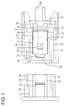
- the slider 60 is inserted into the guide space 27 of the first housing and assembled with the first housing 10 movably in the front-back direction between an initial position (position shown in FIGS. 1 , 3 , 4 and 6 ) and a connection position (position shown in FIGS. 2 and 5 ) while sliding on the guide walls 26.
- the slider 60 is made of synthetic resin, has a rectangular frame shape as a whole and includes a base portion 61 in the form of a plate piece extending along the width direction, a pair of arm portions 62 extending forward from opposite widthwise ends of the base portion 61 and a coupling portion 63 bridged between the front ends of the both arm portions 62 as shown in FIG. 9 .
- the coupling portion 63 is located above the base portion 61 and arranged in an offset manner so as not to overlap the base portion 61 in a front view as shown in FIG. 12 . Further, as shown in FIG. 3 , when the slider 60 is assembled with the first housing 10, the base portion 61 is located on the side of the deflection space 42 located below the releasing portion 22 of the lock arm 17 and the coupling portion 63 is located on an upper surface side of the front end part of the lock arm 17.
- connection position holding portion 64 substantially in the form of a rectangular recess is formed in a widthwise central part of the rear end of the coupling portion 63. As shown in FIG. 5 , when the slider 60 is at the connection position, the connection position holding receiving portion 23 of the lock arm 17 is inserted into the connection position holding portion 64 to rest thereon.
- a pair of spring accommodating portions 65 capable of accommodating the spring members 80 are formed below the both arm portions 62.
- the spring member 80 is formed by a known spring such as a compression coil spring and resiliently expandable and contractible in the front-back direction.
- the spring accommodating portion 65 is formed into a substantially hollow cylindrical shape and the spring member 80 can be entirely accommodated therein.
- the spring accommodating portion 65 includes first and second spring receiving portions 67, 68 on front and rear sides for receiving and supporting opposite front and rear ends of the spring member 80.
- the first and second spring receiving portions 67, 68 are arranged at positions not overlapping each other in a front view in consideration of the removal of a forming mold for the slider 60 in the front-back direction.
- an opening portion 66 open inward and downward is formed in a front part of the spring accommodating portion 65.
- the spring member 80 When the spring member 80 is mounted into the spring accommodating portion 65 as shown in FIG. 6 , a lower part of the front end of the spring member 80 is arranged in an exposed manner below the first spring receiving portion 67. This causes the pressing portions 94 of the second housing 90 to be introduced into the opening portions 66 while pushing the lower parts of the front ends of the spring members 80 in the process of connecting the first and second housings 10, 90. Further, the second spring receiving portion 68 can receive a spring force of the spring member 80 by coming into contact with the lower part of the front end of the spring member 80.
- the both arm portions 62 are formed with a pair of protection walls 73 standing substantially vertically upward from the spring accommodating portions 65. As shown in FIG. 6 , in the case of assembling the slider 60 with the first housing 10, the both protection walls 73 are located to cover opposite widthwise ends of the lock arm 17.
- pair of guide main bodies 74 capable of guiding a movement of the slider 60 are formed on upper end parts of the both arm portions 62.
- the guiding main bodies 74 have such a substantially arcuate cross-section as to protrude outwardly from the upper ends of the both protection walls 73 and then hang downwardly.
- push-in portions 75 inclined upwardly in a step-like manner from the rear end toward a front side are formed on the rear ends of the both arm portions 62.
- the push-in portions 75 are pressed forward, whereby the slider 60 can be moved toward the initial position.
- the initial position holding portion 76 capable of regulating a movement of the slider 60 to the connection position is deflectably formed on the base portion 61. As shown in FIG. 9 , the initial position holding portion 76 is cantilevered forward from a widthwise central part of the upper surface of the base portion 61. As shown in FIG. 11 , the locking projection 77 is formed to project downward on the tip part of the initial position holding portion 76. As shown in FIG. 3 , the locking projection 77 is hooked and locked to the initial position holding receiving portion 25 when the slider 60 is at the initial position. Further, an inclined surface 53 inclined obliquely downwardly is formed on the front surface of the tip part of the initial position holding portion 76. Further, the initial position holding portion 76 includes a base-like thickened portion 78 formed by gradually increasing a thickness of an upper part from a base end part coupled to the base portion 61 to a substantially central area in the front-back direction.
- the structure of the connector of this embodiment is as described above. Next, an assembling method and a connecting operation of the connector are described.
- the spring members 80 are accommodated into the spring accommodating portions 65 of the slider 60.
- the spring members 80 are inserted into the spring accommodating portions 65 through the opening portions 66.
- the front ends of the spring members 80 are supported on the first spring receiving portions 67 and the rear ends of the spring members 80 are supported on the second spring receiving portions 68.
- the slider 60 is inserted into the guide space 27 of the first housing 10 from behind.
- the base portion 61 is located in the deflection space 42 below the releasing portion 22 of the lock arm 17, the protection walls 73 enter clearances between the guide walls 26 and the lock arm 17, and the coupling portion 63 is located above the arm main body 19.
- the initial position holding portion 76 passes through the through hole 24 and, as shown in FIG. 3 , the locking projection 77 is arranged to be lockable to the initial position holding receiving portion 25 to prevent a backward detachment of the slider 60.
- the front ends of the spring accommodating portions 65 are arranged to be able to come into contact with the stopper walls 32 to regulate a forward displacement of the slider 60. In this way, the slider 60 is held at the initial position with respect to the first housing 10 with forward and backward movements thereof regulated.
- the front and rear ends of the spring members 80 are supported on the first and second spring receiving portions 67, 68 when the slider 60 is at the initial position. Further, at the initial position, the thickened portion 78 is located before the deflection space 42 on the side of the releasing portion 22 on the lock arm 17, thereby enabling the deflection of the lock arm 17. Furthermore, with the slider 60 assembled with the first housing 10, the upper surfaces of the base portion 61 and the both arm portions 62 are arranged in an exposed manner substantially at the same height positions as the upper end of the releasing portion 22.
- the receptacle 91 of the second housing 90 is fitted into the connection space 13 of the first housing 10.
- the pressing portions 94 of the second housing 90 enter the spring accommodating portions 65 to come into contact with the lower parts of the front ends of the spring members 80.
- the front ends of the spring members 80 are pressed by the pressing portions 94 to be separated from the first spring receiving portions 67 and the spring members 80 are resiliently compressed while being supported on the second spring receiving portions 68.
- the spring members 80 accumulate their spring forces while applying the spring forces to the slider 60.
- the releasing portion 96 of the second housing 90 comes into contact with the tip part of the initial position holding portion 76 and slides on the inclined surface 53 in a final stage of the connecting process of the first and second housings 10, 90 and, associated with that, the initial position holding portion 76 is deflected and deformed with the base end part thereof as a supporting point.
- first and second housings 10, 90 reach the proper connection position, locking between the locking projection 77 of the initial position holding portion 76 and the initial position holding receiving portion 25 is released. Associated with that, the spring forces accumulated in the spring members 80 are released and the spring members 80 are going to return to a natural state. According to such returning movements of the spring members 80, the second spring receiving portions 68 of the slider 60 are pressed by the spring members 80 and the entire slider 60 is moved backward.
- the spring accommodating portions 65 slide on the inner surfaces of the guide walls 26 and the guide ribs 31 slide on the protection walls 73 and the guiding main bodies 74, thereby guiding the movement of the slider 60.
- the spring members 80 substantially return to the natural state and the connection position holding receiving portion 23 of the lock arm 17 comes into contact with the connection position holding portion 64 of the slider 60, thereby regulating any further retracting movement of the slider 60.
- the thickened portion 78 is located in the deflection space 42 on the side of the releasing portion 22 of the lock arm 17 and arranged in proximity to the lower surface of the lock arm 17 on the side of the releasing portion 22 as shown in FIG. 5 . Even if an external matter (including a finger) accidentally comes into contact with the releasing portion 22 of the lock arm 17 from above in this state, the lock arm 17 comes into contact with the thickened portion 78, whereby any further deflection is regulated to prevent the releasing portion 22 from being operated inadvertently operated for unlocking.
- the push-in portions 75 are first pressed with fingers to push the slider 60 forward. Then, the spring members 80 are resiliently compressed and the pressing portions 94 are pressed by the spring members 80. As the slider 60 moves forward, the thickened portion 78 is retracted from its position below the releasing portion 22 and the deflection of the lock arm 17 is permitted. If the releasing portion 22 is pressed to lift up the front end part of the lock arm 17 in that state, the lock projection 21 is separated from the lock portion 92. As the locking state of the lock arm 17 is released in this way, the spring members 80 press the pressing portions 94 forward and the first housing 10 is separated from the second housing 90 by those pressing forces (spring forces).
- connection position holding portion 64 provided on the coupling portion 63 of the slider 60 comes into contact with the connection position holding receiving portion 23 of the lock arm 17 to prevent a detachment of the slider 60.
- the initial position holding portion 76 provided on the base portion 61 of the slider 60 resiliently locks the initial position holding receiving portion 25 of the housing main body 11 to regulate an inadvertent movement of the slider 60 to the connection position.
- the connection position holding receiving portion 23 is not provided on a ceiling wall covering the slider 60 unlike before and the ceiling wall is omitted from the connector.
- the base portion 61 is inserted into the deflection space 42, which is a dead space between the lock arm 17 and the housing main body 11, and an accommodation space for the base portion 61 is not specially provided in the connector. Thus, the enlargement of the connector can be avoided.
- the movement of the slider 60 is guided by the guiding main bodies 74 formed on the both arm portions 62 connecting the coupling portion 63 and the base portion 61, it is not necessary to provide the slider 60 with a dedicated guide structure for guiding a movement separately from the both arm portions 62 and the configuration of the slider 60 can be simplified.
- the slider 60 is excellent in shape stability.
- the initial position holding portion 76 projects into a frame defined by the slider 60, the surrounding of the initial position holding portion 76 is protected and a situation where the initial position holding portion 76 is broken or fractured due to interference with an external matter is avoided.
- connection position holding receiving portion 23 projects on the arm main body 19 of the lock arm 17 and the connection position holding portion 64 is provided by recessing the coupling portion 63, it is prevented that a contact state of the connection position holding portion 64 and the connection position holding receiving portion 23 is inadvertently released at the connection position.
Landscapes
- Details Of Connecting Devices For Male And Female Coupling (AREA)
- Connector Housings Or Holding Contact Members (AREA)
Abstract
Description
- The present invention relates to a connector.
- A connector disclosed in
patent literature 1 includes first and second housings connectable to each other (called "male and female connectors" in patent literature 1) and a slider (called a "front slider and a rear slider" in patent literature 1) movably assembled with the first housing. A coil spring is incorporated into the slider. When a connecting operation is stopped in the process of connecting the first and second housings, a spring force of the coil spring accumulated thus far is released and the first and second housings are moved and biased in directions separating from each other, thereby preventing the first and second housings from being left in an incompletely connected state. - Further, the first housing includes a tubular receptacle into which the second housing is fittable, and an accommodating chamber capable of accommodating the slider is provided on a ceiling part of the receptacle. When the slider is accommodated into the accommodating chamber, the ceiling wall of the accommodating chamber is located above the slider and a holding portion (called a "butting portion" in patent literature 1) is locked to a holding receiving portion (called a "locking step portion" in patent literature 1) formed on the ceiling wall, thereby preventing a detachment of the slider from the first housing.
- Patent literature 1:
- Japanese Unexamined Patent Publication No.
2002-184526 - In the above case, since the ceiling wall is arranged to cover the slider from above, there is a problem of increasing a height of the connector by a thickness of the ceiling wall. Thus, although it is desired to omit the ceiling wall from the first housing, the holding receiving portion is also eliminated if the ceiling wall is merely omitted, wherefore a detachment of the slider cannot be prevented. This is an unfavorable situation.
- The present invention was completed based on the above situation and aims to prevent a detachment of a slider while avoiding the enlargement of a connector.
- The present invention is directed to a connector with a second housing including a lock portion, a first housing connectable to the second housing, and a slider assembled with the first housing movably between an initial position and a connection position and configured to be moved from the initial position to the connection position as the first and second housings are properly connected, wherein the first housing includes a housing main body configured such that the second housing is externally fittable thereon and a lock arm configured to form a deflection space between the lock arm and the housing main body and hold the first and second housings in a connected state by resiliently locking the lock portion, the lock arm includes a connection position holding receiving portion on a surface on a side opposite to a surface facing the housing main body, the housing main body includes an initial position holding receiving portion on a surface facing the lock arm, the slider includes a base portion extending along a width direction and to be inserted into the deflection space, a pair of arm portions projecting from opposite widthwise end parts of the base portion and a coupling portion coupling projecting end parts of the both arm portions and facing the surface of the lock arm on the opposite side, an initial position holding portion configured to regulate a movement of the slider to the connection position by resiliently locking the initial position holding receiving portion at the initial position is deflectably provided on the base portion, and a connection position holding portion configured to regulate a detachment of the slider by coming into contact with the connection position holding receiving portion at the connection position is provided on the coupling portion.
- When the slider reaches the connection position, the connection position holding portion provided on the coupling portion of the slider comes into contact with the connection position holding receiving portion of the lock arm to regulate a detachment of the slider. Further, when the slider is at the initial position, the initial position holding portion provided on the base portion of the slider resiliently locks the initial position holding receiving portion of the housing main body to regulate an inadvertent movement of the slider to the connection position.
- Since the connection position holding receiving portion is not provided on a ceiling wall covering the slider in the above case, the ceiling wall can be omitted from the connector. Further, since the base portion is inserted into the deflection space, which is a dead space between the lock arm and the housing main body, it is not necessary to provide the connector with a dedicated insertion space for the base portion. Thus, the enlargement of the connector can be avoided.
-
-
FIG. 1 is a plan view showing a state where first and second housings are arranged right opposite to each other in a connector of one embodiment, -
FIG. 2 is a plan view showing a state where the first and second housings are properly connected to each other, -
FIG. 3 is a section showing the state where the first and second housings are arranged right opposite to each other, -
FIG. 4 is a section showing a state in a final stage of the process of connecting the first and second housings, -
FIG. 5 is a section showing the state where the first and second housings are properly connected to each other, -
FIG. 6 is a front view of the connector, -
FIG. 7 is a front view of the first housing, -
FIG. 8 is a plan view of the first housing, -
FIG. 9 is a plan view of a slider, -
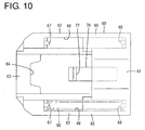
FIG. 10 is a bottom view of the slider, -
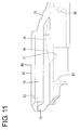
FIG. 11 is a side view of the slider, and -
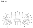
FIG. 12 is a front view of the slider. - Preferred embodiments of the present invention are described below.
- The first housing includes a pair of guide walls located at opposite widthwise sides of the lock arm and the both arm portions slide on the both guide walls to guide a movement of the slider. Since the movement of the slider is guided by the both arm portions connecting the coupling portion and the base portion, it is not necessary to provide the slider with a dedicated guide structure for guiding a movement and the configuration of the slider can be simplified.
- The slider is formed into a frame shape as a whole by the base portion, the both arm portions and the coupling portion, and the initial position holding portion projects into a frame defined by the slider. Since the entire slider is formed into the frame shape, the slider is structured to be excellent in shape stability. Further, since the initial position holding portion projects into the frame defined by the slider, the surrounding of the initial position holding portion is protected and a situation where the initial position holding portion is broken or fractured by interference with an external matter can be avoided.
- The connection position holding receiving portion projects on a main body part of the lock arm, and the connection position holding portion is provided by recessing the coupling portion so that the connection position holding receiving portion is insertable thereinto. This prevents a contact state of the connection position holding portion and the connection position holding receiving portion from being inadvertently released at the connection position.
- One embodiment of the present invention is described with reference to
FIGS. 1 to 12 . This embodiment includes first andsecond housings slider 60 to be assembled with thefirst housing 10,spring members 80 to be assembled with theslider 60,first terminal fittings 20 to be mounted into thefirst housing 10 andsecond terminal fittings 99 to be mounted into thesecond housing 90. Note that, in the following description, connection surface sides of the first andsecond housings FIG. 3 . - The
second housing 90 is made of synthetic resin and includes, as shown inFIG. 3 , atubular receptacle 91.Tabs 95 of thesecond terminal fittings 99 are arranged to project into thereceptacle 91. Alock portion 92 is provided to project on the upper surface of the upper wall of thereceptacle 91. Further, as shown inFIG. 1 , a pair ofguide projections 93 are formed to extend in the front-back direction at opposite widthwise sides of thelock portion 92 on the upper surface of the upper wall of thereceptacle 91 and, further, a pair ofpressing portions 94 are formed to extend in the front-back direction at opposite outer sides of the bothguide projections 93. As shown inFIG. 4 , a releasingportion 96 capable of releasing locking between an initialposition holding portion 76 and an initial position holding receivingportion 25 to be described later is formed on the opening edge of the front end of the upper wall of thereceptacle 91. - The
first housing 10 is likewise made of synthetic resin and includes, as shown inFIGS. 3 and7 , a block-like housingmain body 11 and a tubularfitting tube portion 12 surrounding the housingmain body 11. Aconnection space 13 into which thereceptacle 91 is fittable is formed to be open forward between the housingmain body 11 and thefitting tube portion 12. A plurality ofcavities 14 are formed to penetrate through the housingmain body 11 in the front-back direction. In the case of this embodiment, as shown inFIG. 7 , a pair ofcavities 14 are arranged side by side anddeflectable locking lances 15 are formed to project on the lower surfaces of thecavities 14. The firstterminal fitting 20 is inserted into eachcavity 14. As shown inFIG. 3 , thefirst terminal fitting 20 is crimped and connected to a conductor part of awire 100 and crimped and connected to arubber plug 200 fitted on thewire 100. When being properly inserted into eachcavity 14, thefirst terminal fitting 20 is resiliently locked and retained by thelocking lance 15, therubber plug 200 is inserted into a rear end part of thecavity 14 to seal the interior of thecavity 14 in a liquid-tight manner and thewire 100 is drawn out from the rear end of the housingmain body 11. - As shown in
FIG. 3 , astep 16 is formed on the outer peripheral surface of the housingmain body 11 and a front area before thestep 16 is slightly recessed from a rear area behind thestep 16. Aseal ring 300 is fitted before thestep 16 on the outer peripheral surface of the housingmain body 11. As shown inFIG. 5 , thereceptacle 91 is inserted into theconnection space 13 and theseal ring 300 is resiliently compressed between thereceptacle 91 and the housingmain body 11 at the time of connecting the first andsecond housings second housings - As shown in
FIG. 3 , a cap-like front member 400 is mounted on a front end part of the outer peripheral surface of the housingmain body 11. Theabove seal ring 300 is prevented from coming out forward by thefront member 400. - Further, a
lock arm 17 is coupled to the upper end of the outer peripheral surface of the housingmain body 11 as shown inFIG. 5 . Thelock arm 17 includes an arm supportingpoint portion 18 standing upward from the outer peripheral surface of the housingmain body 11 and an armmain body 19 extending both forward and backward from the upper end of the arm supportingpoint portion 18. Alock projection 21 is formed to project downward on a front end part of the armmain body 19 and a releasingportion 22 is formed to be slightly higher on a rear end part of the armmain body 19. - As shown in
FIG. 4 , thelock projection 21 interferes with thelock portion 92 and the armmain body 19 is deflected and deformed with the arm supportingpoint portion 18 as a supporting point in the process of connecting the first andsecond housings second housings FIG. 5 , the armmain body 19 resiliently returns, thelock projection 21 is arranged to be able to lock thelock portion 92 and the first andsecond housings second housings portion 22 is pushed down toward a deflection space 42 (seeFIG. 3 ) located therebelow to separate thelock projection 21 from thelock portion 92 with theslider 60 pushed forward and retracted from thedeflection space 42, whereby the first andsecond housings - Further, as shown in
FIG. 5 , a connection position holding receivingportion 23 for regulating a backward detachment of theslider 60 is formed on a front end part of the upper surface of the armmain body 19. As shown inFIG. 8 , the connection position holding receivingportion 23 is in the form of a rib extending in a width direction. Further, as shown inFIG. 7 , a throughhole 24 is formed in a widthwise central part of the arm supportingpoint portion 18. As shown inFIG. 5 , the initial position holding receivingportion 25 stepped from the upper surface of the housingmain body 11 is formed below the throughhole 24 on the arm supportingpoint portion 18 and behind thestep 16. The later-described initialposition holding portion 76 of theslider 60 can pass through the throughhole 24 and a later-describedlocking projection 77 formed on a tip part of the initialposition holding portion 76 passed through the throughhole 24 is lockable to the initial position holding receiving portion 25 (seeFIG. 3 ). - As shown in
FIG. 8 , a part of the upper wall of thefitting tube portion 12 facing thelock arm 17 is open and the upper surface of thelock arm 17 is exposed. Here, the upper wall of thefitting tube portion 12 includes a pair ofguide walls 26 at opposite sides of thelock arm 17. The bothguide walls 26 extend backward from the front end of the housingmain body 11 and aguide space 27 for guiding a movement of theslider 60 is formed by the bothguide walls 26 and the housingmain body 11. - Rear parts of the both
guide walls 26 have a substantially quarter-circular arcuate cross-section open upward and project further backward than the rear end of the housingmain body 11. Front parts of the bothguide walls 26 have a substantially quarter-circular arcuate cross-section open on a side facing thelock arm 17. As shown inFIG. 7 , a pair ofguide ribs 31 are formed to stand on the front parts of the bothguide walls 26. The both guideribs 31 extend in the front-back direction along the inner edges of the bothguide walls 26 and are arranged at positions facing opposite widthwise ends of a front part of the armmain body 19. - Further, a pair of
stopper walls 32 for closing a front side of theguide space 27 are formed to protrude on the front ends of the both guide walls 26 (seeFIG. 6 ). The front end of theslider 60 comes into contact with thestopper walls 32, thereby regulating any further forward movement of theslider 60. - Next, the
slider 60 is described. Theslider 60 is inserted into theguide space 27 of the first housing and assembled with thefirst housing 10 movably in the front-back direction between an initial position (position shown inFIGS. 1 ,3 ,4 and6 ) and a connection position (position shown inFIGS. 2 and5 ) while sliding on theguide walls 26. Specifically, theslider 60 is made of synthetic resin, has a rectangular frame shape as a whole and includes abase portion 61 in the form of a plate piece extending along the width direction, a pair ofarm portions 62 extending forward from opposite widthwise ends of thebase portion 61 and acoupling portion 63 bridged between the front ends of the botharm portions 62 as shown inFIG. 9 . - The
coupling portion 63 is located above thebase portion 61 and arranged in an offset manner so as not to overlap thebase portion 61 in a front view as shown inFIG. 12 . Further, as shown inFIG. 3 , when theslider 60 is assembled with thefirst housing 10, thebase portion 61 is located on the side of thedeflection space 42 located below the releasingportion 22 of thelock arm 17 and thecoupling portion 63 is located on an upper surface side of the front end part of thelock arm 17. - Further, as shown in
FIG. 9 , a connectionposition holding portion 64 substantially in the form of a rectangular recess is formed in a widthwise central part of the rear end of thecoupling portion 63. As shown inFIG. 5 , when theslider 60 is at the connection position, the connection position holding receivingportion 23 of thelock arm 17 is inserted into the connectionposition holding portion 64 to rest thereon. - As shown in
FIG. 10 , a pair ofspring accommodating portions 65 capable of accommodating thespring members 80 are formed below the botharm portions 62. Note that thespring member 80 is formed by a known spring such as a compression coil spring and resiliently expandable and contractible in the front-back direction. - The
spring accommodating portion 65 is formed into a substantially hollow cylindrical shape and thespring member 80 can be entirely accommodated therein. Thespring accommodating portion 65 includes first and secondspring receiving portions spring member 80. As shown inFIG. 12 , the first and secondspring receiving portions slider 60 in the front-back direction. Further, as shown inFIG. 10 , an openingportion 66 open inward and downward is formed in a front part of thespring accommodating portion 65. - When the
spring member 80 is mounted into thespring accommodating portion 65 as shown inFIG. 6 , a lower part of the front end of thespring member 80 is arranged in an exposed manner below the firstspring receiving portion 67. This causes thepressing portions 94 of thesecond housing 90 to be introduced into the openingportions 66 while pushing the lower parts of the front ends of thespring members 80 in the process of connecting the first andsecond housings spring receiving portion 68 can receive a spring force of thespring member 80 by coming into contact with the lower part of the front end of thespring member 80. - As shown in
FIG. 12 , the botharm portions 62 are formed with a pair ofprotection walls 73 standing substantially vertically upward from thespring accommodating portions 65. As shown inFIG. 6 , in the case of assembling theslider 60 with thefirst housing 10, the bothprotection walls 73 are located to cover opposite widthwise ends of thelock arm 17. - Further, pair of guide
main bodies 74 capable of guiding a movement of theslider 60 are formed on upper end parts of the botharm portions 62. The guidingmain bodies 74 have such a substantially arcuate cross-section as to protrude outwardly from the upper ends of the bothprotection walls 73 and then hang downwardly. When theslider 60 is assembled with thefirst housing 10, theguide ribs 31 are fitted and inserted into between the guidingmain bodies 74 and theprotection walls 73 as shown inFIG. 6 . In the process of moving theslider 60, theguide ribs 31 slide on the guidingmain bodies 74 and theprotection walls 73, thereby guiding a movement of theslider 60. - Further, as shown in
FIG. 11 , push-inportions 75 inclined upwardly in a step-like manner from the rear end toward a front side are formed on the rear ends of the botharm portions 62. The push-inportions 75 are pressed forward, whereby theslider 60 can be moved toward the initial position. - The initial
position holding portion 76 capable of regulating a movement of theslider 60 to the connection position is deflectably formed on thebase portion 61. As shown inFIG. 9 , the initialposition holding portion 76 is cantilevered forward from a widthwise central part of the upper surface of thebase portion 61. As shown inFIG. 11 , the lockingprojection 77 is formed to project downward on the tip part of the initialposition holding portion 76. As shown inFIG. 3 , the lockingprojection 77 is hooked and locked to the initial position holding receivingportion 25 when theslider 60 is at the initial position. Further, aninclined surface 53 inclined obliquely downwardly is formed on the front surface of the tip part of the initialposition holding portion 76. Further, the initialposition holding portion 76 includes a base-like thickenedportion 78 formed by gradually increasing a thickness of an upper part from a base end part coupled to thebase portion 61 to a substantially central area in the front-back direction. - The structure of the connector of this embodiment is as described above. Next, an assembling method and a connecting operation of the connector are described.
- First, the
spring members 80 are accommodated into thespring accommodating portions 65 of theslider 60. Thespring members 80 are inserted into thespring accommodating portions 65 through the openingportions 66. Then, the front ends of thespring members 80 are supported on the firstspring receiving portions 67 and the rear ends of thespring members 80 are supported on the secondspring receiving portions 68. - Subsequently, the
slider 60 is inserted into theguide space 27 of thefirst housing 10 from behind. In the process of inserting theslider 60, thebase portion 61 is located in thedeflection space 42 below the releasingportion 22 of thelock arm 17, theprotection walls 73 enter clearances between theguide walls 26 and thelock arm 17, and thecoupling portion 63 is located above the armmain body 19. When theslider 60 is properly assembled, the initialposition holding portion 76 passes through the throughhole 24 and, as shown inFIG. 3 , the lockingprojection 77 is arranged to be lockable to the initial position holding receivingportion 25 to prevent a backward detachment of theslider 60. Further, when theslider 60 is properly assembled, the front ends of thespring accommodating portions 65 are arranged to be able to come into contact with thestopper walls 32 to regulate a forward displacement of theslider 60. In this way, theslider 60 is held at the initial position with respect to thefirst housing 10 with forward and backward movements thereof regulated. - Note that the front and rear ends of the
spring members 80 are supported on the first and secondspring receiving portions slider 60 is at the initial position. Further, at the initial position, the thickenedportion 78 is located before thedeflection space 42 on the side of the releasingportion 22 on thelock arm 17, thereby enabling the deflection of thelock arm 17. Furthermore, with theslider 60 assembled with thefirst housing 10, the upper surfaces of thebase portion 61 and the botharm portions 62 are arranged in an exposed manner substantially at the same height positions as the upper end of the releasingportion 22. - Subsequently, the
receptacle 91 of thesecond housing 90 is fitted into theconnection space 13 of thefirst housing 10. In the connecting process, thepressing portions 94 of thesecond housing 90 enter thespring accommodating portions 65 to come into contact with the lower parts of the front ends of thespring members 80. As the connection further progresses, the front ends of thespring members 80 are pressed by thepressing portions 94 to be separated from the firstspring receiving portions 67 and thespring members 80 are resiliently compressed while being supported on the secondspring receiving portions 68. During this time, thespring members 80 accumulate their spring forces while applying the spring forces to theslider 60. - Further, as shown in
FIG. 4 , the releasingportion 96 of thesecond housing 90 comes into contact with the tip part of the initialposition holding portion 76 and slides on theinclined surface 53 in a final stage of the connecting process of the first andsecond housings position holding portion 76 is deflected and deformed with the base end part thereof as a supporting point. - Thereafter, when the first and
second housings lock arm 17 is resiliently locked to thelock portion 92 and the first andsecond housings FIG. 5 . Simultaneously, the first and secondterminal fittings - Further, when the first and
second housings projection 77 of the initialposition holding portion 76 and the initial position holding receivingportion 25 is released. Associated with that, the spring forces accumulated in thespring members 80 are released and thespring members 80 are going to return to a natural state. According to such returning movements of thespring members 80, the secondspring receiving portions 68 of theslider 60 are pressed by thespring members 80 and theentire slider 60 is moved backward. - In the process of moving the
slider 60, thespring accommodating portions 65 slide on the inner surfaces of theguide walls 26 and theguide ribs 31 slide on theprotection walls 73 and the guidingmain bodies 74, thereby guiding the movement of theslider 60. When theslider 60 reaches the connection position as shown inFIG. 5 , thespring members 80 substantially return to the natural state and the connection position holding receivingportion 23 of thelock arm 17 comes into contact with the connectionposition holding portion 64 of theslider 60, thereby regulating any further retracting movement of theslider 60. By visually confirming that theslider 60 has reached the connection position in this way, it can be known that the first andsecond housings - When the
slider 60 is at the connection position, the thickenedportion 78 is located in thedeflection space 42 on the side of the releasingportion 22 of thelock arm 17 and arranged in proximity to the lower surface of thelock arm 17 on the side of the releasingportion 22 as shown inFIG. 5 . Even if an external matter (including a finger) accidentally comes into contact with the releasingportion 22 of thelock arm 17 from above in this state, thelock arm 17 comes into contact with the thickenedportion 78, whereby any further deflection is regulated to prevent the releasingportion 22 from being operated inadvertently operated for unlocking. - On the other hand, if the connecting operation is stopped before the first and
second housings pressing portions 94 are pushed back by the spring forces of thespring members 80 accumulated in the connecting process and the first andsecond housings second housings - Further, in separating the first and
second housings portions 75 are first pressed with fingers to push theslider 60 forward. Then, thespring members 80 are resiliently compressed and thepressing portions 94 are pressed by thespring members 80. As theslider 60 moves forward, the thickenedportion 78 is retracted from its position below the releasingportion 22 and the deflection of thelock arm 17 is permitted. If the releasingportion 22 is pressed to lift up the front end part of thelock arm 17 in that state, thelock projection 21 is separated from thelock portion 92. As the locking state of thelock arm 17 is released in this way, thespring members 80 press thepressing portions 94 forward and thefirst housing 10 is separated from thesecond housing 90 by those pressing forces (spring forces). - As described above, when the
slider 60 reaches the connection position, the connectionposition holding portion 64 provided on thecoupling portion 63 of theslider 60 comes into contact with the connection position holding receivingportion 23 of thelock arm 17 to prevent a detachment of theslider 60. Further, when theslider 60 is at the initial position, the initialposition holding portion 76 provided on thebase portion 61 of theslider 60 resiliently locks the initial position holding receivingportion 25 of the housingmain body 11 to regulate an inadvertent movement of theslider 60 to the connection position. In this case, the connection position holding receivingportion 23 is not provided on a ceiling wall covering theslider 60 unlike before and the ceiling wall is omitted from the connector. Further, thebase portion 61 is inserted into thedeflection space 42, which is a dead space between thelock arm 17 and the housingmain body 11, and an accommodation space for thebase portion 61 is not specially provided in the connector. Thus, the enlargement of the connector can be avoided. - Further, since the movement of the
slider 60 is guided by the guidingmain bodies 74 formed on the botharm portions 62 connecting thecoupling portion 63 and thebase portion 61, it is not necessary to provide theslider 60 with a dedicated guide structure for guiding a movement separately from the botharm portions 62 and the configuration of theslider 60 can be simplified. - Further, since the
entire slider 60 is formed into a frame shape, theslider 60 is excellent in shape stability. In addition, since the initialposition holding portion 76 projects into a frame defined by theslider 60, the surrounding of the initialposition holding portion 76 is protected and a situation where the initialposition holding portion 76 is broken or fractured due to interference with an external matter is avoided. - Furthermore, since the connection position holding receiving
portion 23 projects on the armmain body 19 of thelock arm 17 and the connectionposition holding portion 64 is provided by recessing thecoupling portion 63, it is prevented that a contact state of the connectionposition holding portion 64 and the connection position holding receivingportion 23 is inadvertently released at the connection position. - The present invention is not limited to the above described and illustrated embodiment. For example, the following modes are also included in the technical scope of the present invention.
- (1) The spring members may be interposed between the first housing and the slider.
- (2) The slider may be configured to move forward from the initial position toward the connection position.
- (3) A locking recess may be formed instead of the locking projection on the tip part of the initial position holding portion and the initial position holding receiving portion may be in the form of a projection hookable to the locking recess instead of in the form of a recess.
- (4) Conversely to the above embodiment, the connection position holding portion may project on the coupling portion of the slider and the connection position holding receiving portion may be provided by recessing the tip part of the lock arm so that the projection-like connection position holding portion is insertable thereinto.
-
- 10
- first housing
- 11
- housing main body
- 17
- lock arm
- 23
- connection position holding receiving portion
- 25
- initial position holding receiving portion
- 42
- deflection space
- 60
- slider
- 61
- base portion
- 62
- arm portion
- 63
- coupling portion
- 64
- connection position holding portion
- 76
- initial position holding portion
- 80
- spring member
- 90
- second housing
- 91
- receptacle
- 92
- lock portion
- 96
- releasing portion
Claims (4)
- A connector, comprising:a second housing including a lock portion;a first housing connectable to the second housing; anda slider assembled with the first housing movably between an initial position and a connection position and configured to be moved from the initial position to the connection position as the first and second housings are properly connected;wherein:the first housing includes a housing main body configured such that the second housing is externally fittable thereon and a lock arm configured to form a deflection space between the lock arm and the housing main body and hold the first and second housings in a connected state by resiliently locking the lock portion;the lock arm includes a connection position holding receiving portion on a surface on a side opposite to a surface facing the housing main body;the housing main body includes an initial position holding receiving portion on a surface facing the lock arm;the slider includes a base portion extending along a width direction and to be inserted into the deflection space, a pair of arm portions projecting from opposite widthwise end parts of the base portion and a coupling portion coupling projecting end parts of the both arm portions and facing the surface of the lock arm on the opposite side;an initial position holding portion configured to regulate a movement of the slider to the connection position by resiliently locking the initial position holding receiving portion at the initial position is deflectably provided on the base portion; anda connection position holding portion configured to regulate a detachment of the slider by coming into contact with the connection position holding receiving portion at the connection position is provided on the coupling portion.
- A connector according to claim 1, wherein the first housing includes a pair of guide walls located at opposite widthwise sides of the lock arm and the both arm portions slide on the both guide walls to guide a movement of the slider.
- A connector according to claim 1 or 2, wherein the slider is formed into a frame shape as a whole by the base portion, the both arm portions and the coupling portion, and the initial position holding portion projects into a frame defined by the slider.
- A connector according to any one of claims 1 to 3, wherein the connection position holding receiving portion projects on a main body part of the lock arm, and the connection position holding portion is provided by recessing the coupling portion so that the connection position holding receiving portion is insertable thereinto.
Applications Claiming Priority (1)
| Application Number | Priority Date | Filing Date | Title |
|---|---|---|---|
| PCT/JP2013/062976 WO2014181415A1 (en) | 2013-05-08 | 2013-05-08 | Connector |
Publications (2)
| Publication Number | Publication Date |
|---|---|
| EP2996207A1 true EP2996207A1 (en) | 2016-03-16 |
| EP2996207A4 EP2996207A4 (en) | 2016-04-27 |
Family
ID=51866919
Family Applications (1)
| Application Number | Title | Priority Date | Filing Date |
|---|---|---|---|
| EP13884360.2A Withdrawn EP2996207A4 (en) | 2013-05-08 | 2013-05-08 | Connector |
Country Status (6)
| Country | Link |
|---|---|
| US (1) | US9543697B2 (en) |
| EP (1) | EP2996207A4 (en) |
| JP (1) | JP5863084B2 (en) |
| KR (1) | KR101740170B1 (en) |
| CN (1) | CN105191010B (en) |
| WO (1) | WO2014181415A1 (en) |
Families Citing this family (17)
| Publication number | Priority date | Publication date | Assignee | Title |
|---|---|---|---|---|
| DE102015201089A1 (en) * | 2015-01-22 | 2016-07-28 | Te Connectivity Germany Gmbh | Intermediate housing with a CPA receptacle and connector systems comprising such |
| JP6254982B2 (en) * | 2015-09-09 | 2017-12-27 | 矢崎総業株式会社 | connector |
| DE102016117219A1 (en) * | 2016-03-10 | 2017-09-14 | Voss Automotive Gmbh | Guided plug connection |
| CN106918080B (en) * | 2017-03-21 | 2018-01-09 | 绿瓴(北京)环保节能科技有限公司 | A kind of air cleaning unit |
| CN106731282B (en) * | 2017-03-24 | 2018-06-05 | 安徽原上草节能环保科技有限公司 | A kind of air cleaning unit |
| US10763615B2 (en) * | 2017-06-06 | 2020-09-01 | Nippon Tanshi Co., Ltd. | Connector structure having a longitudinal movement restricting protrusion |
| CN111066207B (en) * | 2017-08-31 | 2021-04-23 | 矢崎总业株式会社 | Part locking structure |
| JP2019050169A (en) * | 2017-09-12 | 2019-03-28 | 住友電装株式会社 | connector |
| JP6660409B2 (en) * | 2018-02-13 | 2020-03-11 | 矢崎総業株式会社 | connector |
| KR102647188B1 (en) * | 2018-11-14 | 2024-03-13 | 현대자동차주식회사 | Connector device |
| JP7066596B2 (en) * | 2018-11-16 | 2022-05-13 | ホシデン株式会社 | connector |
| JP6993377B2 (en) * | 2019-03-28 | 2022-01-13 | ヒロセ電機株式会社 | Connector device and board mounting method |
| JP6936280B2 (en) * | 2019-06-04 | 2021-09-15 | 矢崎総業株式会社 | connector |
| WO2021010261A1 (en) * | 2019-07-16 | 2021-01-21 | タイコエレクトロニクスジャパン合同会社 | Connector |
| JP7286086B2 (en) * | 2019-07-31 | 2023-06-05 | 日本圧着端子製造株式会社 | CONNECTOR HOUSING AND METHOD OF MANUFACTURING CONNECTOR HOUSING |
| KR102440790B1 (en) * | 2021-02-26 | 2022-09-07 | 주식회사 경신 | connector |
| CN115117669B (en) * | 2021-03-19 | 2025-07-04 | 泰科电子(上海)有限公司 | Connectors and Connector Assemblies |
Family Cites Families (12)
| Publication number | Priority date | Publication date | Assignee | Title |
|---|---|---|---|---|
| JPH08162215A (en) * | 1994-12-08 | 1996-06-21 | Yazaki Corp | Connector locking mechanism |
| JP4075288B2 (en) | 2000-06-16 | 2008-04-16 | 住友電装株式会社 | connector |
| JP3593959B2 (en) * | 2000-08-10 | 2004-11-24 | 住友電装株式会社 | connector |
| JP2002184526A (en) | 2000-12-11 | 2002-06-28 | Sumitomo Wiring Syst Ltd | Connector |
| JP3656830B2 (en) * | 2001-02-16 | 2005-06-08 | 住友電装株式会社 | connector |
| JP3862147B2 (en) | 2001-04-04 | 2006-12-27 | 矢崎総業株式会社 | Connector coupling detection device |
| JP3804491B2 (en) * | 2001-08-22 | 2006-08-02 | 住友電装株式会社 | connector |
| JP2006086090A (en) | 2004-09-17 | 2006-03-30 | Sumitomo Wiring Syst Ltd | Connector |
| JP4419875B2 (en) | 2005-03-14 | 2010-02-24 | 住友電装株式会社 | Mating detection connector |
| JP5050820B2 (en) | 2007-12-05 | 2012-10-17 | 住友電装株式会社 | connector |
| WO2014181416A1 (en) * | 2013-05-08 | 2014-11-13 | 住友電装株式会社 | Connector |
| WO2014181414A1 (en) * | 2013-05-08 | 2014-11-13 | 住友電装株式会社 | Connector |
-
2013
- 2013-05-08 CN CN201380076452.1A patent/CN105191010B/en active Active
- 2013-05-08 EP EP13884360.2A patent/EP2996207A4/en not_active Withdrawn
- 2013-05-08 KR KR1020157030477A patent/KR101740170B1/en active Active
- 2013-05-08 US US14/787,517 patent/US9543697B2/en active Active
- 2013-05-08 JP JP2015515685A patent/JP5863084B2/en active Active
- 2013-05-08 WO PCT/JP2013/062976 patent/WO2014181415A1/en not_active Ceased
Also Published As
| Publication number | Publication date |
|---|---|
| US9543697B2 (en) | 2017-01-10 |
| KR20150134399A (en) | 2015-12-01 |
| EP2996207A4 (en) | 2016-04-27 |
| WO2014181415A1 (en) | 2014-11-13 |
| CN105191010A (en) | 2015-12-23 |
| JPWO2014181415A1 (en) | 2017-02-23 |
| CN105191010B (en) | 2017-08-25 |
| JP5863084B2 (en) | 2016-02-16 |
| US20160079703A1 (en) | 2016-03-17 |
| KR101740170B1 (en) | 2017-05-25 |
Similar Documents
| Publication | Publication Date | Title |
|---|---|---|
| US9543697B2 (en) | Connector having a housing with a fitting tube with guide walls with a lock arm inbettween | |
| US9515410B2 (en) | Connector with a slider releasably locked to a housing by a resilient stopper having two points of support for resilient deflection | |
| US9543702B2 (en) | Connector | |
| US9231342B2 (en) | Connector | |
| US8523594B2 (en) | Connector | |
| JP5614369B2 (en) | Terminal fitting | |
| US9711915B2 (en) | Connector having a housing with a backlash preventing rib | |
| EP2637262A1 (en) | Connector, connector assembly and assembling/disassembling method therefor | |
| EP2637261A1 (en) | Connector, connector assembly and assembling method therefor | |
| EP1986288B1 (en) | A shorting terminal, a connector and an assembling method therefor | |
| US9614314B2 (en) | Connector with a deflectable locking lance exposed on an outer surface of a housing | |
| US9543687B2 (en) | Connector | |
| US9362652B2 (en) | Connector with at least one detector | |
| US20170352974A1 (en) | Connector | |
| EP2479849A1 (en) | Connector | |
| EP3324494B1 (en) | Connector | |
| US20160123361A1 (en) | Connector | |
| US12456836B2 (en) | Connector | |
| KR101723327B1 (en) | Connector | |
| EP3139451A1 (en) | Connector, connector assembly and method of assembling it | |
| KR101799098B1 (en) | Connector having holder |
Legal Events
| Date | Code | Title | Description |
|---|---|---|---|
| PUAI | Public reference made under article 153(3) epc to a published international application that has entered the european phase |
Free format text: ORIGINAL CODE: 0009012 |
|
| 17P | Request for examination filed |
Effective date: 20151022 |
|
| AK | Designated contracting states |
Kind code of ref document: A1 Designated state(s): AL AT BE BG CH CY CZ DE DK EE ES FI FR GB GR HR HU IE IS IT LI LT LU LV MC MK MT NL NO PL PT RO RS SE SI SK SM TR |
|
| AX | Request for extension of the european patent |
Extension state: BA ME |
|
| A4 | Supplementary search report drawn up and despatched |
Effective date: 20160330 |
|
| RIC1 | Information provided on ipc code assigned before grant |
Ipc: H01R 13/639 20060101AFI20160322BHEP Ipc: H01R 13/627 20060101ALI20160322BHEP Ipc: H01R 13/641 20060101ALI20160322BHEP |
|
| DAX | Request for extension of the european patent (deleted) | ||
| GRAP | Despatch of communication of intention to grant a patent |
Free format text: ORIGINAL CODE: EPIDOSNIGR1 |
|
| INTG | Intention to grant announced |
Effective date: 20170313 |
|
| STAA | Information on the status of an ep patent application or granted ep patent |
Free format text: STATUS: THE APPLICATION IS DEEMED TO BE WITHDRAWN |
|
| 18D | Application deemed to be withdrawn |
Effective date: 20170725 |