EP2995864A1 - Film cooling circuit for a combustor liner - Google Patents
Film cooling circuit for a combustor liner Download PDFInfo
- Publication number
- EP2995864A1 EP2995864A1 EP15183924.8A EP15183924A EP2995864A1 EP 2995864 A1 EP2995864 A1 EP 2995864A1 EP 15183924 A EP15183924 A EP 15183924A EP 2995864 A1 EP2995864 A1 EP 2995864A1
- Authority
- EP
- European Patent Office
- Prior art keywords
- channel
- substrate
- coating
- hole
- coat
- Prior art date
- Legal status (The legal status is an assumption and is not a legal conclusion. Google has not performed a legal analysis and makes no representation as to the accuracy of the status listed.)
- Granted
Links
Images




Classifications
-
- F—MECHANICAL ENGINEERING; LIGHTING; HEATING; WEAPONS; BLASTING
- F23—COMBUSTION APPARATUS; COMBUSTION PROCESSES
- F23R—GENERATING COMBUSTION PRODUCTS OF HIGH PRESSURE OR HIGH VELOCITY, e.g. GAS-TURBINE COMBUSTION CHAMBERS
- F23R3/00—Continuous combustion chambers using liquid or gaseous fuel
- F23R3/02—Continuous combustion chambers using liquid or gaseous fuel characterised by the air-flow or gas-flow configuration
- F23R3/04—Air inlet arrangements
- F23R3/06—Arrangement of apertures along the flame tube
-
- F—MECHANICAL ENGINEERING; LIGHTING; HEATING; WEAPONS; BLASTING
- F23—COMBUSTION APPARATUS; COMBUSTION PROCESSES
- F23R—GENERATING COMBUSTION PRODUCTS OF HIGH PRESSURE OR HIGH VELOCITY, e.g. GAS-TURBINE COMBUSTION CHAMBERS
- F23R3/00—Continuous combustion chambers using liquid or gaseous fuel
- F23R3/002—Wall structures
-
- F—MECHANICAL ENGINEERING; LIGHTING; HEATING; WEAPONS; BLASTING
- F05—INDEXING SCHEMES RELATING TO ENGINES OR PUMPS IN VARIOUS SUBCLASSES OF CLASSES F01-F04
- F05D—INDEXING SCHEME FOR ASPECTS RELATING TO NON-POSITIVE-DISPLACEMENT MACHINES OR ENGINES, GAS-TURBINES OR JET-PROPULSION PLANTS
- F05D2230/00—Manufacture
- F05D2230/10—Manufacture by removing material
- F05D2230/13—Manufacture by removing material using lasers
-
- F—MECHANICAL ENGINEERING; LIGHTING; HEATING; WEAPONS; BLASTING
- F05—INDEXING SCHEMES RELATING TO ENGINES OR PUMPS IN VARIOUS SUBCLASSES OF CLASSES F01-F04
- F05D—INDEXING SCHEME FOR ASPECTS RELATING TO NON-POSITIVE-DISPLACEMENT MACHINES OR ENGINES, GAS-TURBINES OR JET-PROPULSION PLANTS
- F05D2230/00—Manufacture
- F05D2230/30—Manufacture with deposition of material
-
- F—MECHANICAL ENGINEERING; LIGHTING; HEATING; WEAPONS; BLASTING
- F05—INDEXING SCHEMES RELATING TO ENGINES OR PUMPS IN VARIOUS SUBCLASSES OF CLASSES F01-F04
- F05D—INDEXING SCHEME FOR ASPECTS RELATING TO NON-POSITIVE-DISPLACEMENT MACHINES OR ENGINES, GAS-TURBINES OR JET-PROPULSION PLANTS
- F05D2230/00—Manufacture
- F05D2230/90—Coating; Surface treatment
-
- F—MECHANICAL ENGINEERING; LIGHTING; HEATING; WEAPONS; BLASTING
- F05—INDEXING SCHEMES RELATING TO ENGINES OR PUMPS IN VARIOUS SUBCLASSES OF CLASSES F01-F04
- F05D—INDEXING SCHEME FOR ASPECTS RELATING TO NON-POSITIVE-DISPLACEMENT MACHINES OR ENGINES, GAS-TURBINES OR JET-PROPULSION PLANTS
- F05D2260/00—Function
- F05D2260/20—Heat transfer, e.g. cooling
- F05D2260/202—Heat transfer, e.g. cooling by film cooling
-
- F—MECHANICAL ENGINEERING; LIGHTING; HEATING; WEAPONS; BLASTING
- F23—COMBUSTION APPARATUS; COMBUSTION PROCESSES
- F23R—GENERATING COMBUSTION PRODUCTS OF HIGH PRESSURE OR HIGH VELOCITY, e.g. GAS-TURBINE COMBUSTION CHAMBERS
- F23R2900/00—Special features of, or arrangements for continuous combustion chambers; Combustion processes therefor
- F23R2900/00018—Manufacturing combustion chamber liners or subparts
-
- F—MECHANICAL ENGINEERING; LIGHTING; HEATING; WEAPONS; BLASTING
- F23—COMBUSTION APPARATUS; COMBUSTION PROCESSES
- F23R—GENERATING COMBUSTION PRODUCTS OF HIGH PRESSURE OR HIGH VELOCITY, e.g. GAS-TURBINE COMBUSTION CHAMBERS
- F23R2900/00—Special features of, or arrangements for continuous combustion chambers; Combustion processes therefor
- F23R2900/03041—Effusion cooled combustion chamber walls or domes
-
- F—MECHANICAL ENGINEERING; LIGHTING; HEATING; WEAPONS; BLASTING
- F23—COMBUSTION APPARATUS; COMBUSTION PROCESSES
- F23R—GENERATING COMBUSTION PRODUCTS OF HIGH PRESSURE OR HIGH VELOCITY, e.g. GAS-TURBINE COMBUSTION CHAMBERS
- F23R2900/00—Special features of, or arrangements for continuous combustion chambers; Combustion processes therefor
- F23R2900/03042—Film cooled combustion chamber walls or domes
-
- F—MECHANICAL ENGINEERING; LIGHTING; HEATING; WEAPONS; BLASTING
- F23—COMBUSTION APPARATUS; COMBUSTION PROCESSES
- F23R—GENERATING COMBUSTION PRODUCTS OF HIGH PRESSURE OR HIGH VELOCITY, e.g. GAS-TURBINE COMBUSTION CHAMBERS
- F23R2900/00—Special features of, or arrangements for continuous combustion chambers; Combustion processes therefor
- F23R2900/03043—Convection cooled combustion chamber walls with means for guiding the cooling air flow
-
- Y—GENERAL TAGGING OF NEW TECHNOLOGICAL DEVELOPMENTS; GENERAL TAGGING OF CROSS-SECTIONAL TECHNOLOGIES SPANNING OVER SEVERAL SECTIONS OF THE IPC; TECHNICAL SUBJECTS COVERED BY FORMER USPC CROSS-REFERENCE ART COLLECTIONS [XRACs] AND DIGESTS
- Y02—TECHNOLOGIES OR APPLICATIONS FOR MITIGATION OR ADAPTATION AGAINST CLIMATE CHANGE
- Y02T—CLIMATE CHANGE MITIGATION TECHNOLOGIES RELATED TO TRANSPORTATION
- Y02T50/00—Aeronautics or air transport
- Y02T50/60—Efficient propulsion technologies, e.g. for aircraft
Definitions
- the present disclosure relates to a gas turbine engine and, more particularly, to a combustor liner having film cooling circuits.
- Gas turbine engines such as those that power modern commercial and military aircraft, include a fan section to propel the aircraft, compressor section to pressurize a supply of air from the fan section, a combustor section to bum a hydrocarbon fuel in the presence of the pressurized air, and a turbine section to extract energy from the resultant combustion gases and generate thrust.
- the combustor section may have an annular wall having inner and outer shells that support respective inner and outer heat shielding liners.
- the liners may be comprised of a plurality of floating heat shields or panels that together define an annular combustion chamber.
- An annular cooling plenum is defined between the respective shells and liners for supplying cooling air to an opposite hot side of the panels through a plurality of strategically placed film cooling holes.
- the film cooling holes are generally orientated to create a protective blanket, or, air film over the hot side of the panels, thereby protecting the panels from the hot combustion gases in the chamber.
- a combustor liner defining a combustion chamber and according to one, non-limiting, embodiment of the present disclosure includes a substrate having a hot face and an opposite cold face with a channel communicating through the hot face and an aperture in fluid communication with the channel and extending through the cold face; and a coating disposed over the hot face and defining in-part the channel with a hole in the coating and in fluid communication between the combustion chamber and the channel.
- the coating includes a bond coat in contact with the hot face and defining in-part the channel.
- the coating includes a thermal barrier coat covering the bond coat, and the hole communicates through the bond coat and the thermal barrier coat.
- the hole is a film cooling hole.
- a direction of flow through the aperture is substantially normal to a direction of flow through the channel.
- the direction of flow through the channel is substantially planar to the substrate and angled with a direction of flow through the hole.
- the hole is one of a plurality of holes.
- the channel is defined by a surface of the substrate that substantially faces the combustion chamber and a peripheral side of the substrate that surrounds the bottom surface and spans between the bottom surface and the coating.
- the aperture communicates through the surface.
- the liner includes a pedestal in the channel and extending between and engaged to the surface and the coating.
- a combustor wall assembly includes a liner defining at least in-part a combustion chamber; a shell with a cooling cavity defined between the liner and the shell; and a film cooling circuit extending through the liner and communicating between the cavity and the combustion chamber.
- the liner has a substrate having a first face defining in-part the cooling cavity and an opposite second face, and a coating covering the second face and defining the combustion chamber.
- the film cooling circuit has a channel generally in the substrate and defined by the substrate and the coating, an aperture defined by the substrate and in fluid communication between the cooling cavity and the channel, and at least one film hole in the coating and in fluid communication between the channel and the combustion chamber.
- cooling air flow is diverted from the aperture and to the channel, and is diverted from the channel and to the hole.
- the assembly includes a pedestal in the channel and spanning between the coating and the substrate.
- the coating has a first coat secured to the substrate and a thermal barrier coat secured to the first coat and exposed to the combustion chamber.
- the hole is a laser drilled hole and extends through the first coat and the thermal barrier coat.
- a method of manufacturing a film cooling circuit for a combustor includes the steps of casting a substrate of a panel with a channel of the circuit; placing an insert into the channel; securing a coating over the substrate and the insert; removing the insert; and forming a film hole through the coating that is in fluid communication with the channel.
- the casted substrate has an aperture in fluid communication with the channel and the insert is removed through the aperture.
- the step of securing a coating includes securing a first coat over the substrate and insert then securing a thermal barrier coat over the first coat.
- FIG. 1 schematically illustrates a gas turbine engine 20.
- the gas turbine engine 20 is disclosed herein as a two-spool turbo fan that generally incorporates a fan section 22, a compressor section 24, a combustor section 26 and a turbine section 28.
- Alternative engines might include an augmentor section (not shown) among other systems or features.
- the fan section 22 drives air along a bypass flowpath while the compressor section 24 drives air along a core flowpath for compression and communication into the combustor section 26 then expansion through the turbine section 28.
- an intermediate spool includes an intermediate pressure compressor ("IPC") between a Low Pressure Compressor (“LPC”) and a High Pressure Compressor (“HPC”), and an Intermediate Pressure Turbine (“IPT”) between the High Pressure Turbine (“HPT”) and the Low Pressure Turbine (“LPT”).
- IPC intermediate pressure compressor
- LPC Low Pressure Compressor
- HPC High Pressure Compressor
- IPT Intermediate Pressure Turbine
- the engine 20 generally includes a low spool 30 and a high spool 32 mounted for rotation about an engine central longitudinal axis A relative to an engine static structure 36 or engine case via several bearing structures 38.
- the low spool 30 generally includes an inner shaft 40 that interconnects a fan 42 of the fan section 22, a LPC 44 of the compressor section 24 and a LPT 46 of the turbine section 28.
- the inner shaft 40 drives the fan 42 directly or through a geared architecture 48 to drive the fan 42 at a lower speed than the low spool 30.
- An exemplary reduction transmission is an epicyclic transmission, namely a planetary or star gear system.
- the high spool 32 includes an outer shaft 50 that interconnects a HPC 52 of the compressor section 24 and HPT 54 of the turbine section 28.
- a combustor 56 of the combustor section 26 is arranged between the HPC 52 and the HPT 54.
- the inner shaft 40 and the outer shaft 50 are concentric and rotate about the engine central longitudinal axis A that is collinear with their longitudinal axes. Core airflow is compressed by the LPC 44 then the HPC 52, mixed with the fuel and burned in the combustor 56, then expanded over the HPT 54 and the LPT 46.
- the LPT 46 and HPT 54 rotationally drive the respective low spool 30 and high spool 32 in response to the expansion.
- the gas turbine engine 20 is a high-bypass geared aircraft engine.
- the gas turbine engine 20 bypass ratio is greater than about six (6:1).
- the geared architecture 48 can include an epicyclic gear train, such as a planetary gear system or other gear system.
- the example epicyclic gear train has a gear reduction ratio of greater than about 2.3:1, and in another example is greater than about 2.5:1.
- the geared turbofan enables operation of the low spool 30 at higher speeds that can increase the operational efficiency of the LPC 44 and LPT 46 and render increased pressure in a fewer number of stages.
- a pressure ratio associated with the LPT 46 is pressure measured prior to the inlet of the LPT 46 as related to the pressure at the outlet of the LPT 46 prior to an exhaust nozzle of the gas turbine engine 20.
- the bypass ratio of the gas turbine engine 20 is greater than about ten (10:1)
- the fan diameter is significantly larger than that of the LPC 44
- the LPT 46 has a pressure ratio that is greater than about five (5:1). It should be understood; however, that the above parameters are only exemplary of one embodiment of a geared architecture engine and that the present disclosure is applicable to other gas turbine engines including direct drive turbofans.
- a significant amount of thrust is provided by the bypass flow path B due to the high bypass ratio.
- the fan section 22 of the gas turbine engine 20 is designed for a particular flight condition - typically cruise at about 0.8 Mach and about 35,000 feet (10,668 meters). This flight condition, with the gas turbine engine 20 at its best fuel consumption, is also known as Thrust Specific Fuel Consumption (TSFC).
- TSFC Thrust Specific Fuel Consumption
- Fan Pressure Ratio is the pressure ratio across a blade of the fan section 22 without the use of a Fan Exit Guide Vane System.
- the low Fan Pressure Ratio according to one, non-limiting, embodiment of the example gas turbine engine 20 is less than 1.45.
- Low Corrected Fan Tip Speed is the actual fan tip speed divided by an industry standard temperature correction of ("T" / 518.7) 0.5 in which "T" represents the ambient temperature in degrees Rankine.
- the Low Corrected Fan Tip Speed according to one non-limiting embodiment of the example gas turbine engine 20 is less than about 1,150 feet per second (351 meters per second).
- the combustor section 26 generally includes a combustor 56 with an outer combustor wall assembly 60, an inner combustor wall assembly 62 and a diffuser case module 64 that encases assemblies 60, 62.
- the outer combustor wall assembly 60 and the inner combustor wall assembly 62 are radially spaced apart such that an annular combustion chamber 66 is defined therebetween.
- the outer combustor wall assembly 60 is spaced radially inward from an outer diffuser case 64A of the diffuser case module 64 to define an outer annular plenum 76.
- the inner combustor wall assembly 62 is spaced radially outward from an inner diffuser case 64B of the diffuser case module 64 to define an inner annular plenum 78. It should be understood that although a particular combustor is illustrated, other combustor types with various combustor liner arrangements will also benefit. It should be further understood that the disclosed cooling flow paths are but an illustrated embodiment and should not be limited.
- Each combustor wall assembly 60, 62 generally includes a respective support shell 68, 70 that supports one or more liners 72, 74 mounted thereto.
- Each of the liners 72, 74 may be formed of a plurality of floating heat shields or panels that are generally rectilinear and manufactured of, for example, a nickel based super alloy that may be coated with a ceramic, or other temperature resistant material, and are arranged to form a liner array.
- Each liner may have a plurality of forward panels 72A and a plurality of aft panels 72B that line the outer shell 68.
- a plurality of forward panels 74A and a plurality of aft panels 74B also line the inner shell 70. It should be appreciated that the liner array may alternatively include but a single panel rather than the illustrated axial forward and axial aft panels.
- the combustor 56 further includes a forward assembly 80 immediately downstream of the compressor section 24 to receive compressed airflow therefrom.
- the forward assembly 80 generally includes an annular hood 82, a bulkhead assembly 84, and a plurality of swirlers 90 (one shown).
- Each of the swirlers 90 is circumferentially aligned with one of a plurality of fuel nozzles 86 (one shown) and a respective one of a plurality of hood ports 94.
- the bulkhead assembly 84 includes a bulkhead support shell 96 secured to the combustor walls 60, 62, and a plurality of circumferentially distributed bulkhead heat shields or panels 98 secured to the bulkhead support shell 96 around each of a respective swirler opening 92.
- the bulkhead support shell 96 is generally annular and the plurality of circumferentially distributed bulkhead panels 98 are segmented, typically one to each fuel nozzle 86 and swirler 90.
- the annular hood 82 extends radially between, and is secured to, the forwardmost ends of the combustor wall assemblies 60, 62.
- Each one of the plurality of circumferentially distributed hood ports 94 receives a respective one of the plurality of fuel nozzles 86 and facilitates the direction of compressed air into the forward end of the combustion chamber 66 through the swirler opening 92.
- Each fuel nozzle 86 may be secured to the diffuser case module 64 and projects through one of the hood ports 94 into the respective swirler opening 92.
- the forward assembly 80 introduces core combustion air into the forward section of the combustion chamber 66 while the remainder enters the outer annular plenum 76 and the inner annular plenum 78.
- the plurality of fuel nozzles 86 and adjacent structure generate a blended fuel-air mixture that supports stable combustion in the combustion chamber 66.
- the outer and inner support shells 68, 70 may be mounted adjacent to a first row of Nozzle Guide Vanes (NGVs) 54A in the HPT 54.
- the NGVs 54A are static engine components which direct core airflow combustion gases onto the turbine blades of the first turbine rotor in the turbine section 28 to facilitate the conversion of pressure energy into kinetic energy.
- the core airflow combustion gases are also accelerated by the NGVs 54A because of their convergent shape and are typically given a "spin” or a "swirl” in the direction of turbine rotor rotation.
- the turbine rotor blades absorb this energy to drive the turbine rotor at high speed.
- the heat shield or panel 74B of liner 74 has a generally planar panel substrate 100 covered by a thermal barrier coating 102 that defines a boundary of the annular combustion chamber 66.
- the substrate 100 has a hot or first face 104 covered and thermally protected by the coating 102, and an opposite cold or second face 106.
- An annular cooling cavity 108 of wall assembly 62 is radially defined between the cold side 106 of liner 74 and the shell 70 for generally receiving cooling air from the inner plenum 78 via a plurality of holes 110 (that may be impingement holes) in the shell. Air flowing through the holes 110 may impinge upon the cold face 106 of liner 74.
- the coating 102 may include a bond coat 112 secured directly to the first face 104 of the substrate 100, and a thermal barrier coat 114 that covers the bond coat 112 and is directly exposed to the combustion chamber 66.
- the substrate 100 may be made of a nickel-based super alloy, such as PWA 1455, or other suitable super alloys capable of withstanding elevated temperatures.
- Other materials and/or processes may include equiax, directionally-solidified single-crystal castings, metal powder or forged materials, composites, ceramics and hybrid combinations thereof.
- the bond coat 112 may be associated with a thermal, corrosion prevention, and/or environmental coating system; may be made of any variety of materials including nickel, cobalt, chromium, aluminum, and others; and, may be applied to the substrate via plating, plasma spray, electron beam, vapor deposition cathodic arc, sputtering, or other means.
- the thermal barrier coat 114 may be one or more layers and may be made of ceramic based materials and/or any combination of yttria, zirconium and others. It is further contemplated and understood that the bond coat may be any coat and not necessarily needed for bonding of the thermal barrier coat. For instance, the coat 112 may be made of the same material as the substrate 100.
- the bond coat 112 may have a thickness within the range of 0.002 inches to 0.010 inches (0.051 millimeters to 0.254 millimeters) and preferably within the range of 0.007 inches to 0.010 inches (0.178 millimeters to 0.254 millimeters) to facilitate structural integrity.
- the thermal barrier coat 114 may have a thickness within the range of 0.005 inches to 0.050 inches (0.127 millimeters to 1.27 millimeters).
- the panel 74B of liner 74 further includes a plurality of film cooling circuits 116 for flowing cooling air from the cavity 108, through the panel 74B and into the combustion chamber 66 for generally forming a film of cooling air over the thermal coat 114 for additional thermal protection from the hot combustion gases.
- the film cooling circuit 116 has an aperture 118, a film cooling hole 120 and a channel 122 in fluid communication between the aperture 118 and the hole 120.
- the channel 122 is generally in the substrate 100, and is defined by a bottom surface 124 of the substrate 100 that generally faces toward the combustion chamber 66, a continuous, peripheral, side 126 of the substrate 100 that spans between the surface 124 and the hot face 104 and surrounds the bottom surface 124, and a portion 128 of the bond coat 112 of the coating 102 that spans above or over the channel 122.
- the aperture 118 of the film cooling circuit 116 is in and defined by the substrate 100, and extends through the cold face 106 and the bottom surface 124 to communicate directly between the cavity 108 and the channel 122.
- the hole 120 is in and defined by the coating 102 and extends through the bond coat 112 and the thermal coat 114 to communicate directly between the channel 122 and the combustion chamber 66.
- the aperture 118 is generally offset from the hole 120. That is, the aperture 118 may communicate with one end of the channel 122 and the hole 120 may communicate with an opposite end of the channel.
- the orientations of the aperture 118, the channel 122 and the hole 120 are such that a direction of flow (see arrow 130) in the aperture 118 may be substantially normal to a direction of flow (see arrow 132) in the channel 122, and a direction of flow (see arrow 134) in the hole 120 may be angled with respect to the direction of flow 132.
- the direction of flow 134 may be angled by about thirty degrees to enhance the formation of a film of cooling air across the thermal barrier coat 114. It is further contemplated and understood that this angle may be within a range of about twenty degrees to ninety degrees depending upon a particular location and cooling need.
- cooling circuit 116 may be located anywhere on the panel 74B, location of the circuit near or about specific areas of the panel that are difficult to cool through more traditional film cooling holes, may be particularly advantageous. Such areas may include dilution holes and/or associated grommets 136, panel structural support studs 138, peripheral panel rims 140, and igniter holes 142 (see FIGS. 2 and 3 ). Moreover, the panel 74B application may not be limited to the liner(s) 72, 74 but may also include the bulkhead panels 98.
- the substrate 100 of the panel 74B may be cast by conventional means with the aperture 118 and the channel 122 cast into the substrate.
- a sacrificial insert 144 e.g. wax and/or masking
- the bond coat 112 may be placed over the hot face 104 of the substrate 100 and the insert 144 via metal coating or plating.
- the insert 144 may be removed through the aperture 118 by conventional means.
- the thermal barrier coat 114 may be added over the bond coat 112 via plasma spray or a deposition method as two, non-limiting, examples.
- the film hole 120 may be laser drilled through the coats 112, 114 or machined by other mechanical means. It is further contemplated and understood that the cooling circuit 116, or any portion thereof, may be manufactured by other methods such as additive manufacturing. It is further contemplated and understood that removal of the insert 144 may be achieved through the film cooling holes or a combination of the holes and apertures.
- FIGS. 8 and 9 a second embodiment of a film cooling circuit is illustrated wherein like elements have like identifying numerals except with the addition of a prime symbol.
- the circuit 116' of the second embodiment has an aperture 118', a plurality of film cooling holes 120' (two illustrated as one, non-limiting, example) and a channel 122' in fluid communication between the aperture 118' and the holes 120'.
- the channel 122' is generally in a substrate 100', and is defined by a bottom surface 124' of the substrate 100' that generally faces toward a combustion chamber, a continuous, peripheral, side 126' of the substrate 100' that spans between the bottom surface 124' and a hot face 104' of the substrate 100' and surrounds the surface 124', and a portion 128' of a bond coat 112' of a coating 102' that spans above or over the channel 122'.
- the circuit 116' may further include a stanchion or pedestal 146 that contacts and spans between the bottom surface 124' and the portion 128' of the bond coat 112' for providing additional bond coat support.
- the pedestal 146 may generally be any shape that provides sufficient structural integrity and may further be shaped to guide and distribute cooling air flow from the aperture 118' and to the holes 120'.
- the pedestal 146 may further be cast as one unitary piece with the substrate 100', machined, or later added in a manufacturing operation. It is further contemplated and understood that more than one pedestal 138 may be added for additional structural support and/or flow distribution. It is further contemplated and understood that the pedestals 146 may further be a pin, a wall, or any variety of other structural shapes. Such shapes, or portions thereof, may only facilitate flow distribution, and thus may project from the bottom surface 124' but may fall short of and do not connect to the bond coat 112'.
Landscapes
- Engineering & Computer Science (AREA)
- Chemical & Material Sciences (AREA)
- Combustion & Propulsion (AREA)
- Mechanical Engineering (AREA)
- General Engineering & Computer Science (AREA)
- Turbine Rotor Nozzle Sealing (AREA)
Abstract
Description
- The present disclosure relates to a gas turbine engine and, more particularly, to a combustor liner having film cooling circuits.
- Gas turbine engines, such as those that power modern commercial and military aircraft, include a fan section to propel the aircraft, compressor section to pressurize a supply of air from the fan section, a combustor section to bum a hydrocarbon fuel in the presence of the pressurized air, and a turbine section to extract energy from the resultant combustion gases and generate thrust.
- The combustor section may have an annular wall having inner and outer shells that support respective inner and outer heat shielding liners. The liners may be comprised of a plurality of floating heat shields or panels that together define an annular combustion chamber. An annular cooling plenum is defined between the respective shells and liners for supplying cooling air to an opposite hot side of the panels through a plurality of strategically placed film cooling holes. The film cooling holes are generally orientated to create a protective blanket, or, air film over the hot side of the panels, thereby protecting the panels from the hot combustion gases in the chamber.
- Unfortunately, placing and/or distributing known film cooling holes across the panel to achieve an even temperature distribution is difficult. This difficulty is further aggravated due to structural obstacles and/or panel features that disrupt the formation of the cooling air film. Uneven temperature distributions or panel hotspots create thermal mechanical stresses that lead to cracking and a shortened panel lifespan.
- A combustor liner defining a combustion chamber and according to one, non-limiting, embodiment of the present disclosure includes a substrate having a hot face and an opposite cold face with a channel communicating through the hot face and an aperture in fluid communication with the channel and extending through the cold face; and a coating disposed over the hot face and defining in-part the channel with a hole in the coating and in fluid communication between the combustion chamber and the channel.
- Additionally to the foregoing embodiment, the coating includes a bond coat in contact with the hot face and defining in-part the channel.
- In the alternative or additionally thereto, in the foregoing embodiment, the coating includes a thermal barrier coat covering the bond coat, and the hole communicates through the bond coat and the thermal barrier coat.
- In the alternative or additionally thereto, in the foregoing embodiment, the hole is a film cooling hole.
- In the alternative or additionally thereto, in the foregoing embodiment, a direction of flow through the aperture is substantially normal to a direction of flow through the channel.
- In the alternative or additionally thereto, in the foregoing embodiment, the direction of flow through the channel is substantially planar to the substrate and angled with a direction of flow through the hole.
- In the alternative or additionally thereto, in the foregoing embodiment, the hole is one of a plurality of holes.
- In the alternative or additionally thereto, in the foregoing embodiment, the channel is defined by a surface of the substrate that substantially faces the combustion chamber and a peripheral side of the substrate that surrounds the bottom surface and spans between the bottom surface and the coating.
- In the alternative or additionally thereto, in the foregoing embodiment, the aperture communicates through the surface.
- In the alternative or additionally thereto, in the foregoing embodiment, the liner includes a pedestal in the channel and extending between and engaged to the surface and the coating.
- A combustor wall assembly according to another, non-limiting, embodiment includes a liner defining at least in-part a combustion chamber; a shell with a cooling cavity defined between the liner and the shell; and a film cooling circuit extending through the liner and communicating between the cavity and the combustion chamber.
- Additionally to the foregoing embodiment, the liner has a substrate having a first face defining in-part the cooling cavity and an opposite second face, and a coating covering the second face and defining the combustion chamber.
- In the alternative or additionally thereto, in the foregoing embodiment, the film cooling circuit has a channel generally in the substrate and defined by the substrate and the coating, an aperture defined by the substrate and in fluid communication between the cooling cavity and the channel, and at least one film hole in the coating and in fluid communication between the channel and the combustion chamber.
- In the alternative or additionally thereto, in the foregoing embodiment, cooling air flow is diverted from the aperture and to the channel, and is diverted from the channel and to the hole.
- In the alternative or additionally thereto, in the foregoing embodiment, the assembly includes a pedestal in the channel and spanning between the coating and the substrate.
- In the alternative or additionally thereto, in the foregoing embodiment, the coating has a first coat secured to the substrate and a thermal barrier coat secured to the first coat and exposed to the combustion chamber.
- In the alternative or additionally thereto, in the foregoing embodiment, the hole is a laser drilled hole and extends through the first coat and the thermal barrier coat.
- A method of manufacturing a film cooling circuit for a combustor according to another, non-limiting, embodiment includes the steps of casting a substrate of a panel with a channel of the circuit; placing an insert into the channel; securing a coating over the substrate and the insert; removing the insert; and forming a film hole through the coating that is in fluid communication with the channel.
- Additionally to the foregoing embodiment, the casted substrate has an aperture in fluid communication with the channel and the insert is removed through the aperture.
- In the alternative or additionally thereto, in the foregoing embodiment, the step of securing a coating includes securing a first coat over the substrate and insert then securing a thermal barrier coat over the first coat.
- The foregoing features and elements may be combined in various combinations without exclusivity, unless expressly indicated otherwise. These features and elements as well as the operation thereof will become more apparent in light of the following description and the accompanying drawings. It should be understood, however, the following description and drawings are intended to be exemplary in nature and non-limiting.
- Various features will become apparent to those skilled in the art from the following detailed description of the disclosed non-limiting embodiments. The drawings that accompany the detailed description can be briefly described as follows:
-
FIG. 1 is a schematic cross-section of a gas turbine engine; -
FIG. 2 is a cross-section of a combustor section; -
FIG. 3 is a perspective view of a panel of a liner of the combustor section; -
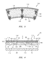
FIG. 4 is a cross section of a combustor wall assembly of the combustor section illustrating film cooling circuits; -
FIG. 5 is a partial plan view of the panel; -
FIG. 6 is a series of cross sections of the film cooling circuit during various stages of manufacturing; -
FIG. 7 is a flow chart of a manufacturing method of the film cooling circuit; -
FIG. 8 is a partial plan view of a panel illustrating a second embodiment of a film cooling circuit; and -
FIG. 9 is a partial cross section of the film cooling circuit taken along line 9-9 ofFIG. 8 . -
FIG. 1 schematically illustrates agas turbine engine 20. Thegas turbine engine 20 is disclosed herein as a two-spool turbo fan that generally incorporates afan section 22, acompressor section 24, acombustor section 26 and aturbine section 28. Alternative engines might include an augmentor section (not shown) among other systems or features. Thefan section 22 drives air along a bypass flowpath while thecompressor section 24 drives air along a core flowpath for compression and communication into thecombustor section 26 then expansion through theturbine section 28. Although depicted as a turbofan in the disclosed non-limiting embodiment, it should be understood that the concepts described herein are not limited to use with turbofans as the teachings may be applied to other types of turbine engines such as a turbojets, turboshafts, and three-spool (plus fan) turbofans wherein an intermediate spool includes an intermediate pressure compressor ("IPC") between a Low Pressure Compressor ("LPC") and a High Pressure Compressor ("HPC"), and an Intermediate Pressure Turbine ("IPT") between the High Pressure Turbine ("HPT") and the Low Pressure Turbine ("LPT"). - The
engine 20 generally includes alow spool 30 and ahigh spool 32 mounted for rotation about an engine central longitudinal axis A relative to an enginestatic structure 36 or engine case viaseveral bearing structures 38. Thelow spool 30 generally includes aninner shaft 40 that interconnects afan 42 of thefan section 22, aLPC 44 of thecompressor section 24 and aLPT 46 of theturbine section 28. Theinner shaft 40 drives thefan 42 directly or through a gearedarchitecture 48 to drive thefan 42 at a lower speed than thelow spool 30. An exemplary reduction transmission is an epicyclic transmission, namely a planetary or star gear system. - The
high spool 32 includes anouter shaft 50 that interconnects aHPC 52 of thecompressor section 24 andHPT 54 of theturbine section 28. Acombustor 56 of thecombustor section 26 is arranged between the HPC 52 and the HPT 54. Theinner shaft 40 and theouter shaft 50 are concentric and rotate about the engine central longitudinal axis A that is collinear with their longitudinal axes. Core airflow is compressed by theLPC 44 then the HPC 52, mixed with the fuel and burned in thecombustor 56, then expanded over the HPT 54 and theLPT 46. TheLPT 46 and HPT 54 rotationally drive the respectivelow spool 30 andhigh spool 32 in response to the expansion. - In one non-limiting example, the
gas turbine engine 20 is a high-bypass geared aircraft engine. In a further example, thegas turbine engine 20 bypass ratio is greater than about six (6:1). The gearedarchitecture 48 can include an epicyclic gear train, such as a planetary gear system or other gear system. The example epicyclic gear train has a gear reduction ratio of greater than about 2.3:1, and in another example is greater than about 2.5:1. The geared turbofan enables operation of thelow spool 30 at higher speeds that can increase the operational efficiency of theLPC 44 andLPT 46 and render increased pressure in a fewer number of stages. - A pressure ratio associated with the
LPT 46 is pressure measured prior to the inlet of theLPT 46 as related to the pressure at the outlet of theLPT 46 prior to an exhaust nozzle of thegas turbine engine 20. In one non-limiting embodiment, the bypass ratio of thegas turbine engine 20 is greater than about ten (10:1), the fan diameter is significantly larger than that of theLPC 44, and theLPT 46 has a pressure ratio that is greater than about five (5:1). It should be understood; however, that the above parameters are only exemplary of one embodiment of a geared architecture engine and that the present disclosure is applicable to other gas turbine engines including direct drive turbofans. - In one embodiment, a significant amount of thrust is provided by the bypass flow path B due to the high bypass ratio. The
fan section 22 of thegas turbine engine 20 is designed for a particular flight condition - typically cruise at about 0.8 Mach and about 35,000 feet (10,668 meters). This flight condition, with thegas turbine engine 20 at its best fuel consumption, is also known as Thrust Specific Fuel Consumption (TSFC). TSFC is an industry standard parameter of fuel consumption per unit of thrust. - Fan Pressure Ratio is the pressure ratio across a blade of the
fan section 22 without the use of a Fan Exit Guide Vane System. The low Fan Pressure Ratio according to one, non-limiting, embodiment of the examplegas turbine engine 20 is less than 1.45. Low Corrected Fan Tip Speed is the actual fan tip speed divided by an industry standard temperature correction of ("T" / 518.7)0.5 in which "T" represents the ambient temperature in degrees Rankine. The Low Corrected Fan Tip Speed according to one non-limiting embodiment of the examplegas turbine engine 20 is less than about 1,150 feet per second (351 meters per second). - With reference to
FIG. 2 , thecombustor section 26 generally includes acombustor 56 with an outercombustor wall assembly 60, an innercombustor wall assembly 62 and adiffuser case module 64 that encasesassemblies combustor wall assembly 60 and the innercombustor wall assembly 62 are radially spaced apart such that anannular combustion chamber 66 is defined therebetween. - The outer
combustor wall assembly 60 is spaced radially inward from anouter diffuser case 64A of thediffuser case module 64 to define an outerannular plenum 76. The innercombustor wall assembly 62 is spaced radially outward from aninner diffuser case 64B of thediffuser case module 64 to define an innerannular plenum 78. It should be understood that although a particular combustor is illustrated, other combustor types with various combustor liner arrangements will also benefit. It should be further understood that the disclosed cooling flow paths are but an illustrated embodiment and should not be limited. - The
combustion chamber 66 contains the combustion products that flow axially toward theturbine section 28. Eachcombustor wall assembly respective support shell more liners liners forward panels 72A and a plurality ofaft panels 72B that line theouter shell 68. A plurality offorward panels 74A and a plurality ofaft panels 74B also line theinner shell 70. It should be appreciated that the liner array may alternatively include but a single panel rather than the illustrated axial forward and axial aft panels. - The
combustor 56 further includes aforward assembly 80 immediately downstream of thecompressor section 24 to receive compressed airflow therefrom. Theforward assembly 80 generally includes anannular hood 82, abulkhead assembly 84, and a plurality of swirlers 90 (one shown). Each of theswirlers 90 is circumferentially aligned with one of a plurality of fuel nozzles 86 (one shown) and a respective one of a plurality ofhood ports 94. Thebulkhead assembly 84 includes abulkhead support shell 96 secured to thecombustor walls panels 98 secured to thebulkhead support shell 96 around each of arespective swirler opening 92. Thebulkhead support shell 96 is generally annular and the plurality of circumferentially distributedbulkhead panels 98 are segmented, typically one to eachfuel nozzle 86 andswirler 90. - The
annular hood 82 extends radially between, and is secured to, the forwardmost ends of thecombustor wall assemblies hood ports 94 receives a respective one of the plurality offuel nozzles 86 and facilitates the direction of compressed air into the forward end of thecombustion chamber 66 through theswirler opening 92. Eachfuel nozzle 86 may be secured to thediffuser case module 64 and projects through one of thehood ports 94 into therespective swirler opening 92. - The
forward assembly 80 introduces core combustion air into the forward section of thecombustion chamber 66 while the remainder enters the outerannular plenum 76 and the innerannular plenum 78. The plurality offuel nozzles 86 and adjacent structure generate a blended fuel-air mixture that supports stable combustion in thecombustion chamber 66. - Opposite the
forward assembly 80, the outer andinner support shells HPT 54. TheNGVs 54A are static engine components which direct core airflow combustion gases onto the turbine blades of the first turbine rotor in theturbine section 28 to facilitate the conversion of pressure energy into kinetic energy. The core airflow combustion gases are also accelerated by theNGVs 54A because of their convergent shape and are typically given a "spin" or a "swirl" in the direction of turbine rotor rotation. The turbine rotor blades absorb this energy to drive the turbine rotor at high speed. - Referring to
FIGS. 3 and 4 , theinner liner 74 andinner shell 70 of theinner wall assembly 62 is illustrated to show one, non-limiting, embodiment of the disclosure; however, it is understood that the same teachings may apply to theouter wall assembly 60. The heat shield orpanel 74B ofliner 74 has a generallyplanar panel substrate 100 covered by athermal barrier coating 102 that defines a boundary of theannular combustion chamber 66. Thesubstrate 100 has a hot orfirst face 104 covered and thermally protected by thecoating 102, and an opposite cold orsecond face 106. Anannular cooling cavity 108 ofwall assembly 62 is radially defined between thecold side 106 ofliner 74 and theshell 70 for generally receiving cooling air from theinner plenum 78 via a plurality of holes 110 (that may be impingement holes) in the shell. Air flowing through theholes 110 may impinge upon thecold face 106 ofliner 74. - The
coating 102 may include abond coat 112 secured directly to thefirst face 104 of thesubstrate 100, and athermal barrier coat 114 that covers thebond coat 112 and is directly exposed to thecombustion chamber 66. Thesubstrate 100 may be made of a nickel-based super alloy, such as PWA 1455, or other suitable super alloys capable of withstanding elevated temperatures. Other materials and/or processes may include equiax, directionally-solidified single-crystal castings, metal powder or forged materials, composites, ceramics and hybrid combinations thereof. Thebond coat 112 may be associated with a thermal, corrosion prevention, and/or environmental coating system; may be made of any variety of materials including nickel, cobalt, chromium, aluminum, and others; and, may be applied to the substrate via plating, plasma spray, electron beam, vapor deposition cathodic arc, sputtering, or other means. Thethermal barrier coat 114 may be one or more layers and may be made of ceramic based materials and/or any combination of yttria, zirconium and others. It is further contemplated and understood that the bond coat may be any coat and not necessarily needed for bonding of the thermal barrier coat. For instance, thecoat 112 may be made of the same material as thesubstrate 100. - The
bond coat 112 may have a thickness within the range of 0.002 inches to 0.010 inches (0.051 millimeters to 0.254 millimeters) and preferably within the range of 0.007 inches to 0.010 inches (0.178 millimeters to 0.254 millimeters) to facilitate structural integrity. Thethermal barrier coat 114 may have a thickness within the range of 0.005 inches to 0.050 inches (0.127 millimeters to 1.27 millimeters). - The
panel 74B ofliner 74 further includes a plurality offilm cooling circuits 116 for flowing cooling air from thecavity 108, through thepanel 74B and into thecombustion chamber 66 for generally forming a film of cooling air over thethermal coat 114 for additional thermal protection from the hot combustion gases. Thefilm cooling circuit 116 has anaperture 118, afilm cooling hole 120 and achannel 122 in fluid communication between theaperture 118 and thehole 120. Thechannel 122 is generally in thesubstrate 100, and is defined by abottom surface 124 of thesubstrate 100 that generally faces toward thecombustion chamber 66, a continuous, peripheral,side 126 of thesubstrate 100 that spans between thesurface 124 and thehot face 104 and surrounds thebottom surface 124, and aportion 128 of thebond coat 112 of thecoating 102 that spans above or over thechannel 122. - Referring to
FIGS. 4 and5 , theaperture 118 of thefilm cooling circuit 116 is in and defined by thesubstrate 100, and extends through thecold face 106 and thebottom surface 124 to communicate directly between thecavity 108 and thechannel 122. Thehole 120 is in and defined by thecoating 102 and extends through thebond coat 112 and thethermal coat 114 to communicate directly between thechannel 122 and thecombustion chamber 66. Theaperture 118 is generally offset from thehole 120. That is, theaperture 118 may communicate with one end of thechannel 122 and thehole 120 may communicate with an opposite end of the channel. The orientations of theaperture 118, thechannel 122 and thehole 120 are such that a direction of flow (see arrow 130) in theaperture 118 may be substantially normal to a direction of flow (see arrow 132) in thechannel 122, and a direction of flow (see arrow 134) in thehole 120 may be angled with respect to the direction offlow 132. The direction of flow 134 may be angled by about thirty degrees to enhance the formation of a film of cooling air across thethermal barrier coat 114. It is further contemplated and understood that this angle may be within a range of about twenty degrees to ninety degrees depending upon a particular location and cooling need. - Although the
cooling circuit 116 may be located anywhere on thepanel 74B, location of the circuit near or about specific areas of the panel that are difficult to cool through more traditional film cooling holes, may be particularly advantageous. Such areas may include dilution holes and/or associatedgrommets 136, panelstructural support studs 138, peripheral panel rims 140, and igniter holes 142 (seeFIGS. 2 and3 ). Moreover, thepanel 74B application may not be limited to the liner(s) 72, 74 but may also include thebulkhead panels 98. - Referring to
FIGS. 6 and7 , a method of manufacturing thefilm cooling circuit 116 is generally illustrated. Asstep 200, thesubstrate 100 of thepanel 74B may be cast by conventional means with theaperture 118 and thechannel 122 cast into the substrate. Asstep 202, a sacrificial insert 144 (e.g. wax and/or masking) may be placed into thechannel 122. Asstep 204, thebond coat 112 may be placed over thehot face 104 of thesubstrate 100 and theinsert 144 via metal coating or plating. Asstep 206, theinsert 144 may be removed through theaperture 118 by conventional means. Asstep 208, thethermal barrier coat 114 may be added over thebond coat 112 via plasma spray or a deposition method as two, non-limiting, examples. As afinal step 210, thefilm hole 120 may be laser drilled through thecoats cooling circuit 116, or any portion thereof, may be manufactured by other methods such as additive manufacturing. It is further contemplated and understood that removal of theinsert 144 may be achieved through the film cooling holes or a combination of the holes and apertures. - Referring to
FIGS. 8 and9 , a second embodiment of a film cooling circuit is illustrated wherein like elements have like identifying numerals except with the addition of a prime symbol. The circuit 116' of the second embodiment has an aperture 118', a plurality of film cooling holes 120' (two illustrated as one, non-limiting, example) and a channel 122' in fluid communication between the aperture 118' and the holes 120'. The channel 122' is generally in a substrate 100', and is defined by a bottom surface 124' of the substrate 100' that generally faces toward a combustion chamber, a continuous, peripheral, side 126' of the substrate 100' that spans between the bottom surface 124' and a hot face 104' of the substrate 100' and surrounds the surface 124', and a portion 128' of a bond coat 112' of a coating 102' that spans above or over the channel 122'. - The circuit 116' may further include a stanchion or
pedestal 146 that contacts and spans between the bottom surface 124' and the portion 128' of the bond coat 112' for providing additional bond coat support. Thepedestal 146 may generally be any shape that provides sufficient structural integrity and may further be shaped to guide and distribute cooling air flow from the aperture 118' and to the holes 120'. Thepedestal 146 may further be cast as one unitary piece with the substrate 100', machined, or later added in a manufacturing operation. It is further contemplated and understood that more than onepedestal 138 may be added for additional structural support and/or flow distribution. It is further contemplated and understood that thepedestals 146 may further be a pin, a wall, or any variety of other structural shapes. Such shapes, or portions thereof, may only facilitate flow distribution, and thus may project from the bottom surface 124' but may fall short of and do not connect to the bond coat 112'. - It is understood that relative positional terms such as "forward," "aft," "upper," "lower," "above," "below," and the like are with reference to the normal operational attitude and should not be considered otherwise limiting. It should be understood that like reference numerals identify corresponding or similar elements throughout the several drawings. It should also be understood that although a particular component arrangement is disclosed in the illustrated embodiment, other arrangements will benefit herefrom. Although particular step sequences are shown, described, and claimed, it should be understood that steps may be performed in any order, separated or combined unless otherwise indicated and will still benefit from the present disclosure.
- The foregoing description is exemplary rather than defined by the limitations within. Various non-limiting embodiments are disclosed herein, however, one of ordinary skill in the art would recognize that various modifications and variations in light of the above teachings will fall within the scope of the appended claims. It is therefore to be understood that within the scope of the appended claims, the disclosure may be practiced other than as specifically described. For that reason the appended claims should be studied to determine true scope and content.
Claims (15)
- A combustor liner defining a combustion chamber, the liner comprising:a substrate (100) having a hot face (104) and an opposite cold face (106) with a channel (122) communicating through the hot face (104) and an aperture (118) in fluid communication with the channel (122) and extending through the cold face (106); anda coating (102) disposed over the hot face (104) and defining in-part the channel (122) with a hole (120) in the coating (102) and in fluid communication between the combustion chamber (66) and the channel (122).
- The combustor liner set forth in claim 1, wherein the coating (102) includes a bond coat (112) in contact with the hot face (104) and defining in-part the channel (122).
- The combustor liner set forth in claim 2, wherein the coating (102) includes a thermal barrier coat (114) covering the bond coat (112), and the hole (120) communicates through the bond coat (112) and the thermal barrier coat (114).
- The combustor liner set forth in claim 1, 2 or 3, wherein the hole (120) is a film cooling hole.
- The combustor liner set forth in any preceding claim, wherein a direction of flow through the aperture (118) is substantially normal to a direction of flow through the channel (122).
- The combustor liner set forth in any preceding claim, wherein the direction of flow through the channel (122) is substantially planar to the substrate (100) and angled with a direction of flow through the hole (120).
- The combustor liner set forth in any preceding claim, wherein the hole (120) is one of a plurality of holes.
- The combustor liner set forth in any preceding claim, wherein the channel (122) is defined by a bottom surface (124) of the substrate (100) that substantially faces the combustion chamber (66) and a peripheral side (126) of the substrate (100) that surrounds the bottom surface (124) and spans between the bottom surface (124) and the coating (102).
- The combustor liner set forth in claim 8, wherein the aperture (118) communicates through the bottom surface (124).
- The combustor liner set forth in claim 8 or 9 further comprising:a pedestal in the channel and extending between and engaged to the bottom surface (124) and the coating (102).
- A combustor wall assembly comprising:a liner (74) defining at least in-part a combustion chamber (66);a shell (70) with a cooling cavity (108) defined between the liner (74) and the shell (70); anda film cooling circuit (116) extending through the liner (74) and communicating between the cavity (108) and the combustion chamber (66).
- The combustor wall assembly set forth in claim 11, wherein the liner (74) has a substrate (100) having a first face (106) defining in-part the cooling cavity (108) and an opposite second face (104), and a coating (102) covering the second face (104) and defining the combustion chamber (66), wherein optionally the film cooling circuit (116) has a channel (122) generally in the substrate (100) and defined by the substrate (100) and the coating (102), an aperture (118) defined by the substrate (100) and in fluid communication between the cooling cavity (108) and the channel (122), and at least one film hole (120) in the coating (102) and in fluid communication between the channel (122) and the combustion chamber (66), wherein optionally cooling air flow is diverted from the aperture (118) and to the channel (102), and is diverted from the channel (102) and to the hole (120); and/or
the combustor wall assembly further comprises a pedestal (146) in the channel (122) and spanning between the coating (102) and the substrate (100). - The combustor wall assembly set forth in claim 12, wherein the coating (102) has a first coat (112) secured to the substrate (100) and a thermal barrier coat (114) secured to the first coat (112) and exposed to the combustion chamber (66);
wherein optionally the hole (120) is a laser drilled hole and extends through the first coat (112) and the thermal barrier coat (114). - A method of manufacturing a film cooling circuit for a combustor comprising the steps of:casting a substrate (100) of a panel (74B) with a channel (122) of the circuit (116);placing an insert (144) into the channel (122);securing a coating (112) over the substrate (100) and the insert (144);removing the insert (144); andforming a film hole (120) through the coating (112) that is in fluid communication with the channel (122).
- The method of manufacturing set forth in claim 14, wherein the casted substrate (100) has an aperture (118) in fluid communication with the channel (122) and the insert (144) is removed through the aperture (118);
wherein the step of securing a coating optionally includes securing a first coat (112) over the substrate (100) and insert (144) then securing a thermal barrier coat (114) over the first coat (112).
Applications Claiming Priority (1)
| Application Number | Priority Date | Filing Date | Title |
|---|---|---|---|
| US201462048055P | 2014-09-09 | 2014-09-09 |
Publications (2)
| Publication Number | Publication Date |
|---|---|
| EP2995864A1 true EP2995864A1 (en) | 2016-03-16 |
| EP2995864B1 EP2995864B1 (en) | 2018-06-06 |
Family
ID=54064233
Family Applications (1)
| Application Number | Title | Priority Date | Filing Date |
|---|---|---|---|
| EP15183924.8A Active EP2995864B1 (en) | 2014-09-09 | 2015-09-04 | Film cooling circuit for a combustor liner and method of manufacturing the film cooling circuit |
Country Status (2)
| Country | Link |
|---|---|
| US (1) | US10731857B2 (en) |
| EP (1) | EP2995864B1 (en) |
Cited By (3)
| Publication number | Priority date | Publication date | Assignee | Title |
|---|---|---|---|---|
| EP3361157A1 (en) * | 2017-02-10 | 2018-08-15 | Rolls-Royce Deutschland Ltd & Co KG | Wall component of a gas turbine with improved cooling |
| EP3453964A1 (en) * | 2017-09-06 | 2019-03-13 | United Technologies Corporation | Dirt collector system |
| EP3734161A1 (en) * | 2019-05-03 | 2020-11-04 | Raytheon Technologies Corporation | Combustor liner panel with micro-circuit core cooling |
Families Citing this family (5)
| Publication number | Priority date | Publication date | Assignee | Title |
|---|---|---|---|---|
| US10132498B2 (en) * | 2015-01-20 | 2018-11-20 | United Technologies Corporation | Thermal barrier coating of a combustor dilution hole |
| WO2019006067A1 (en) * | 2017-06-29 | 2019-01-03 | Siemens Aktiengesellschaft | Method for constructing impingement/effusion cooling features in a component of a combustion turbine engine |
| US10731855B2 (en) | 2017-08-23 | 2020-08-04 | Raytheon Technologies Corporation | Combustor panel cooling arrangements |
| JP6972328B2 (en) * | 2017-10-13 | 2021-11-24 | ゼネラル・エレクトリック・カンパニイ | Coated components with adaptive cooling openings and methods of their manufacture |
| GB202312718D0 (en) | 2023-08-21 | 2023-10-04 | Rolls Royce Plc | Tile for a gas turbine engine combustor |
Citations (5)
| Publication number | Priority date | Publication date | Assignee | Title |
|---|---|---|---|---|
| US5130163A (en) * | 1991-04-26 | 1992-07-14 | General Motors Corporation | Porous laminate surface coating method |
| US20010001897A1 (en) * | 1998-11-12 | 2001-05-31 | Ji Cheng Zhao | Method of forming hollow channels within a component |
| EP1435489A2 (en) * | 2002-12-31 | 2004-07-07 | General Electric Company | High temperature combustor wall and process for manufacturing |
| EP2518270A2 (en) * | 2011-04-27 | 2012-10-31 | General Electric Company | Component and methods of fabricating a coated component using multiple types of fillers |
| EP2584150A2 (en) * | 2011-10-21 | 2013-04-24 | General Electric Company | Components with laser cladding and methods of manufacture |
Family Cites Families (31)
| Publication number | Priority date | Publication date | Assignee | Title |
|---|---|---|---|---|
| US3741824A (en) * | 1970-10-29 | 1973-06-26 | United Aircraft Corp | Method to improve the weldability and formability of nickel-base superalloys |
| US5419681A (en) * | 1993-01-25 | 1995-05-30 | General Electric Company | Film cooled wall |
| US5421158A (en) * | 1994-10-21 | 1995-06-06 | General Electric Company | Segmented centerbody for a double annular combustor |
| US6402470B1 (en) * | 1999-10-05 | 2002-06-11 | United Technologies Corporation | Method and apparatus for cooling a wall within a gas turbine engine |
| US6896487B2 (en) * | 2003-08-08 | 2005-05-24 | United Technologies Corporation | Microcircuit airfoil mainbody |
| US7363763B2 (en) * | 2003-10-23 | 2008-04-29 | United Technologies Corporation | Combustor |
| US7270175B2 (en) | 2004-01-09 | 2007-09-18 | United Technologies Corporation | Extended impingement cooling device and method |
| US6868675B1 (en) * | 2004-01-09 | 2005-03-22 | Honeywell International Inc. | Apparatus and method for controlling combustor liner carbon formation |
| US20060016191A1 (en) * | 2004-07-23 | 2006-01-26 | Honeywell International Inc. | Combined effusion and thick TBC cooling method |
| US7464554B2 (en) | 2004-09-09 | 2008-12-16 | United Technologies Corporation | Gas turbine combustor heat shield panel or exhaust panel including a cooling device |
| US7413808B2 (en) | 2004-10-18 | 2008-08-19 | United Technologies Corporation | Thermal barrier coating |
| US7785076B2 (en) * | 2005-08-30 | 2010-08-31 | Siemens Energy, Inc. | Refractory component with ceramic matrix composite skeleton |
| US20070116972A1 (en) * | 2005-11-21 | 2007-05-24 | United Technologies Corporation | Barrier coating system for refractory metal core |
| US8359866B2 (en) | 2010-02-04 | 2013-01-29 | United Technologies Corporation | Combustor liner segment seal member |
| US8359865B2 (en) | 2010-02-04 | 2013-01-29 | United Technologies Corporation | Combustor liner segment seal member |
| US8499566B2 (en) * | 2010-08-12 | 2013-08-06 | General Electric Company | Combustor liner cooling system |
| US20120114868A1 (en) * | 2010-11-10 | 2012-05-10 | General Electric Company | Method of fabricating a component using a fugitive coating |
| US8739404B2 (en) * | 2010-11-23 | 2014-06-03 | General Electric Company | Turbine components with cooling features and methods of manufacturing the same |
| US8753071B2 (en) * | 2010-12-22 | 2014-06-17 | General Electric Company | Cooling channel systems for high-temperature components covered by coatings, and related processes |
| US8475945B2 (en) | 2011-06-23 | 2013-07-02 | United Technologies Corporation | Composite article including silicon oxycarbide layer |
| US9057523B2 (en) * | 2011-07-29 | 2015-06-16 | United Technologies Corporation | Microcircuit cooling for gas turbine engine combustor |
| US8978385B2 (en) * | 2011-07-29 | 2015-03-17 | United Technologies Corporation | Distributed cooling for gas turbine engine combustor |
| US9021675B2 (en) | 2011-08-15 | 2015-05-05 | United Technologies Corporation | Method for repairing fuel nozzle guides for gas turbine engine combustors using cold metal transfer weld technology |
| US8683814B2 (en) | 2012-02-15 | 2014-04-01 | United Technologies Corporation | Gas turbine engine component with impingement and lobed cooling hole |
| US9243801B2 (en) * | 2012-06-07 | 2016-01-26 | United Technologies Corporation | Combustor liner with improved film cooling |
| US9194585B2 (en) * | 2012-10-04 | 2015-11-24 | United Technologies Corporation | Cooling for combustor liners with accelerating channels |
| US9080447B2 (en) * | 2013-03-21 | 2015-07-14 | General Electric Company | Transition duct with divided upstream and downstream portions |
| US20160281204A1 (en) * | 2013-11-18 | 2016-09-29 | United Technologies Corporation | Thermal barrier coating repair |
| US9476306B2 (en) * | 2013-11-26 | 2016-10-25 | General Electric Company | Components with multi-layered cooling features and methods of manufacture |
| EP3018415B1 (en) * | 2014-11-07 | 2020-01-01 | United Technologies Corporation | Combustor dilution hole cooling |
| US10508809B2 (en) * | 2016-10-31 | 2019-12-17 | General Electric Company | Articles for high temperature service and methods for making |
-
2015
- 2015-09-02 US US14/843,578 patent/US10731857B2/en active Active
- 2015-09-04 EP EP15183924.8A patent/EP2995864B1/en active Active
Patent Citations (5)
| Publication number | Priority date | Publication date | Assignee | Title |
|---|---|---|---|---|
| US5130163A (en) * | 1991-04-26 | 1992-07-14 | General Motors Corporation | Porous laminate surface coating method |
| US20010001897A1 (en) * | 1998-11-12 | 2001-05-31 | Ji Cheng Zhao | Method of forming hollow channels within a component |
| EP1435489A2 (en) * | 2002-12-31 | 2004-07-07 | General Electric Company | High temperature combustor wall and process for manufacturing |
| EP2518270A2 (en) * | 2011-04-27 | 2012-10-31 | General Electric Company | Component and methods of fabricating a coated component using multiple types of fillers |
| EP2584150A2 (en) * | 2011-10-21 | 2013-04-24 | General Electric Company | Components with laser cladding and methods of manufacture |
Cited By (4)
| Publication number | Priority date | Publication date | Assignee | Title |
|---|---|---|---|---|
| EP3361157A1 (en) * | 2017-02-10 | 2018-08-15 | Rolls-Royce Deutschland Ltd & Co KG | Wall component of a gas turbine with improved cooling |
| EP3453964A1 (en) * | 2017-09-06 | 2019-03-13 | United Technologies Corporation | Dirt collector system |
| US11187413B2 (en) | 2017-09-06 | 2021-11-30 | Raytheon Technologies Corporation | Dirt collector system |
| EP3734161A1 (en) * | 2019-05-03 | 2020-11-04 | Raytheon Technologies Corporation | Combustor liner panel with micro-circuit core cooling |
Also Published As
| Publication number | Publication date |
|---|---|
| US20160069569A1 (en) | 2016-03-10 |
| US10731857B2 (en) | 2020-08-04 |
| EP2995864B1 (en) | 2018-06-06 |
Similar Documents
| Publication | Publication Date | Title |
|---|---|---|
| EP2995864B1 (en) | Film cooling circuit for a combustor liner and method of manufacturing the film cooling circuit | |
| US11073284B2 (en) | Cooled grommet for a combustor wall assembly | |
| US10247419B2 (en) | Combustor liner panel with a multiple of heat transfer ribs for a gas turbine engine combustor | |
| EP2995863B1 (en) | Single-walled combustor for a gas turbine engine and method of manufacture | |
| EP3032175B1 (en) | A cooled wall assembly for a combustor and method of design | |
| EP3077728B1 (en) | Gas turbine engine combustor having co-swirl orientation of combustor effusion passages, and method | |
| EP3018415B1 (en) | Combustor dilution hole cooling | |
| US10830448B2 (en) | Combustor liner panel with a multiple of heat transfer augmentors for a gas turbine engine combustor | |
| EP3321586B1 (en) | Gas turbine engine combustor having a coated combustor panel shell and method for manufacturing the combustor | |
| US20140174091A1 (en) | Repair procedure for a gas turbine engine via variable polarity welding | |
| US10669939B2 (en) | Combustor seal for a gas turbine engine combustor | |
| EP4328488B1 (en) | Gas turbine combustor with liner panel having a radiused gate | |
| EP3318803B1 (en) | Stud arrangement for gas turbine engine combustor | |
| EP3315862B1 (en) | Cast combustor liner panel with a radius edge for gas turbine engine combustor | |
| EP3315864B1 (en) | Cast combustor liner panel with radiused dilution passage grommet for a gas turbine engine combustor |
Legal Events
| Date | Code | Title | Description |
|---|---|---|---|
| PUAI | Public reference made under article 153(3) epc to a published international application that has entered the european phase |
Free format text: ORIGINAL CODE: 0009012 |
|
| AK | Designated contracting states |
Kind code of ref document: A1 Designated state(s): AL AT BE BG CH CY CZ DE DK EE ES FI FR GB GR HR HU IE IS IT LI LT LU LV MC MK MT NL NO PL PT RO RS SE SI SK SM TR |
|
| AX | Request for extension of the european patent |
Extension state: BA ME |
|
| 17P | Request for examination filed |
Effective date: 20160915 |
|
| RAP1 | Party data changed (applicant data changed or rights of an application transferred) |
Owner name: UNITED TECHNOLOGIES CORPORATION |
|
| RBV | Designated contracting states (corrected) |
Designated state(s): AL AT BE BG CH CY CZ DE DK EE ES FI FR GB GR HR HU IE IS IT LI LT LU LV MC MK MT NL NO PL PT RO RS SE SI SK SM TR |
|
| GRAP | Despatch of communication of intention to grant a patent |
Free format text: ORIGINAL CODE: EPIDOSNIGR1 |
|
| STAA | Information on the status of an ep patent application or granted ep patent |
Free format text: STATUS: GRANT OF PATENT IS INTENDED |
|
| INTG | Intention to grant announced |
Effective date: 20171208 |
|
| GRAS | Grant fee paid |
Free format text: ORIGINAL CODE: EPIDOSNIGR3 |
|
| GRAA | (expected) grant |
Free format text: ORIGINAL CODE: 0009210 |
|
| STAA | Information on the status of an ep patent application or granted ep patent |
Free format text: STATUS: THE PATENT HAS BEEN GRANTED |
|
| AK | Designated contracting states |
Kind code of ref document: B1 Designated state(s): AL AT BE BG CH CY CZ DE DK EE ES FI FR GB GR HR HU IE IS IT LI LT LU LV MC MK MT NL NO PL PT RO RS SE SI SK SM TR |
|
| REG | Reference to a national code |
Ref country code: GB Ref legal event code: FG4D |
|
| REG | Reference to a national code |
Ref country code: CH Ref legal event code: EP Ref country code: AT Ref legal event code: REF Ref document number: 1006511 Country of ref document: AT Kind code of ref document: T Effective date: 20180615 |
|
| REG | Reference to a national code |
Ref country code: IE Ref legal event code: FG4D |
|
| REG | Reference to a national code |
Ref country code: DE Ref legal event code: R096 Ref document number: 602015011682 Country of ref document: DE |
|
| REG | Reference to a national code |
Ref country code: FR Ref legal event code: PLFP Year of fee payment: 4 |
|
| REG | Reference to a national code |
Ref country code: NL Ref legal event code: MP Effective date: 20180606 |
|
| REG | Reference to a national code |
Ref country code: LT Ref legal event code: MG4D |
|
| PG25 | Lapsed in a contracting state [announced via postgrant information from national office to epo] |
Ref country code: CY Free format text: LAPSE BECAUSE OF FAILURE TO SUBMIT A TRANSLATION OF THE DESCRIPTION OR TO PAY THE FEE WITHIN THE PRESCRIBED TIME-LIMIT Effective date: 20180606 Ref country code: LT Free format text: LAPSE BECAUSE OF FAILURE TO SUBMIT A TRANSLATION OF THE DESCRIPTION OR TO PAY THE FEE WITHIN THE PRESCRIBED TIME-LIMIT Effective date: 20180606 Ref country code: FI Free format text: LAPSE BECAUSE OF FAILURE TO SUBMIT A TRANSLATION OF THE DESCRIPTION OR TO PAY THE FEE WITHIN THE PRESCRIBED TIME-LIMIT Effective date: 20180606 Ref country code: BG Free format text: LAPSE BECAUSE OF FAILURE TO SUBMIT A TRANSLATION OF THE DESCRIPTION OR TO PAY THE FEE WITHIN THE PRESCRIBED TIME-LIMIT Effective date: 20180906 Ref country code: SE Free format text: LAPSE BECAUSE OF FAILURE TO SUBMIT A TRANSLATION OF THE DESCRIPTION OR TO PAY THE FEE WITHIN THE PRESCRIBED TIME-LIMIT Effective date: 20180606 Ref country code: ES Free format text: LAPSE BECAUSE OF FAILURE TO SUBMIT A TRANSLATION OF THE DESCRIPTION OR TO PAY THE FEE WITHIN THE PRESCRIBED TIME-LIMIT Effective date: 20180606 Ref country code: NO Free format text: LAPSE BECAUSE OF FAILURE TO SUBMIT A TRANSLATION OF THE DESCRIPTION OR TO PAY THE FEE WITHIN THE PRESCRIBED TIME-LIMIT Effective date: 20180906 |
|
| PG25 | Lapsed in a contracting state [announced via postgrant information from national office to epo] |
Ref country code: LV Free format text: LAPSE BECAUSE OF FAILURE TO SUBMIT A TRANSLATION OF THE DESCRIPTION OR TO PAY THE FEE WITHIN THE PRESCRIBED TIME-LIMIT Effective date: 20180606 Ref country code: HR Free format text: LAPSE BECAUSE OF FAILURE TO SUBMIT A TRANSLATION OF THE DESCRIPTION OR TO PAY THE FEE WITHIN THE PRESCRIBED TIME-LIMIT Effective date: 20180606 Ref country code: GR Free format text: LAPSE BECAUSE OF FAILURE TO SUBMIT A TRANSLATION OF THE DESCRIPTION OR TO PAY THE FEE WITHIN THE PRESCRIBED TIME-LIMIT Effective date: 20180907 Ref country code: RS Free format text: LAPSE BECAUSE OF FAILURE TO SUBMIT A TRANSLATION OF THE DESCRIPTION OR TO PAY THE FEE WITHIN THE PRESCRIBED TIME-LIMIT Effective date: 20180606 |
|
| REG | Reference to a national code |
Ref country code: AT Ref legal event code: MK05 Ref document number: 1006511 Country of ref document: AT Kind code of ref document: T Effective date: 20180606 |
|
| PG25 | Lapsed in a contracting state [announced via postgrant information from national office to epo] |
Ref country code: NL Free format text: LAPSE BECAUSE OF FAILURE TO SUBMIT A TRANSLATION OF THE DESCRIPTION OR TO PAY THE FEE WITHIN THE PRESCRIBED TIME-LIMIT Effective date: 20180606 |
|
| PG25 | Lapsed in a contracting state [announced via postgrant information from national office to epo] |
Ref country code: IS Free format text: LAPSE BECAUSE OF FAILURE TO SUBMIT A TRANSLATION OF THE DESCRIPTION OR TO PAY THE FEE WITHIN THE PRESCRIBED TIME-LIMIT Effective date: 20181006 Ref country code: AT Free format text: LAPSE BECAUSE OF FAILURE TO SUBMIT A TRANSLATION OF THE DESCRIPTION OR TO PAY THE FEE WITHIN THE PRESCRIBED TIME-LIMIT Effective date: 20180606 Ref country code: PL Free format text: LAPSE BECAUSE OF FAILURE TO SUBMIT A TRANSLATION OF THE DESCRIPTION OR TO PAY THE FEE WITHIN THE PRESCRIBED TIME-LIMIT Effective date: 20180606 Ref country code: CZ Free format text: LAPSE BECAUSE OF FAILURE TO SUBMIT A TRANSLATION OF THE DESCRIPTION OR TO PAY THE FEE WITHIN THE PRESCRIBED TIME-LIMIT Effective date: 20180606 Ref country code: SK Free format text: LAPSE BECAUSE OF FAILURE TO SUBMIT A TRANSLATION OF THE DESCRIPTION OR TO PAY THE FEE WITHIN THE PRESCRIBED TIME-LIMIT Effective date: 20180606 Ref country code: RO Free format text: LAPSE BECAUSE OF FAILURE TO SUBMIT A TRANSLATION OF THE DESCRIPTION OR TO PAY THE FEE WITHIN THE PRESCRIBED TIME-LIMIT Effective date: 20180606 Ref country code: EE Free format text: LAPSE BECAUSE OF FAILURE TO SUBMIT A TRANSLATION OF THE DESCRIPTION OR TO PAY THE FEE WITHIN THE PRESCRIBED TIME-LIMIT Effective date: 20180606 |
|
| PG25 | Lapsed in a contracting state [announced via postgrant information from national office to epo] |
Ref country code: SM Free format text: LAPSE BECAUSE OF FAILURE TO SUBMIT A TRANSLATION OF THE DESCRIPTION OR TO PAY THE FEE WITHIN THE PRESCRIBED TIME-LIMIT Effective date: 20180606 Ref country code: IT Free format text: LAPSE BECAUSE OF FAILURE TO SUBMIT A TRANSLATION OF THE DESCRIPTION OR TO PAY THE FEE WITHIN THE PRESCRIBED TIME-LIMIT Effective date: 20180606 |
|
| REG | Reference to a national code |
Ref country code: DE Ref legal event code: R097 Ref document number: 602015011682 Country of ref document: DE |
|
| PLBE | No opposition filed within time limit |
Free format text: ORIGINAL CODE: 0009261 |
|
| STAA | Information on the status of an ep patent application or granted ep patent |
Free format text: STATUS: NO OPPOSITION FILED WITHIN TIME LIMIT |
|
| PG25 | Lapsed in a contracting state [announced via postgrant information from national office to epo] |
Ref country code: MC Free format text: LAPSE BECAUSE OF FAILURE TO SUBMIT A TRANSLATION OF THE DESCRIPTION OR TO PAY THE FEE WITHIN THE PRESCRIBED TIME-LIMIT Effective date: 20180606 |
|
| REG | Reference to a national code |
Ref country code: CH Ref legal event code: PL |
|
| 26N | No opposition filed |
Effective date: 20190307 |
|
| PG25 | Lapsed in a contracting state [announced via postgrant information from national office to epo] |
Ref country code: SI Free format text: LAPSE BECAUSE OF FAILURE TO SUBMIT A TRANSLATION OF THE DESCRIPTION OR TO PAY THE FEE WITHIN THE PRESCRIBED TIME-LIMIT Effective date: 20180606 Ref country code: DK Free format text: LAPSE BECAUSE OF FAILURE TO SUBMIT A TRANSLATION OF THE DESCRIPTION OR TO PAY THE FEE WITHIN THE PRESCRIBED TIME-LIMIT Effective date: 20180606 |
|
| REG | Reference to a national code |
Ref country code: BE Ref legal event code: MM Effective date: 20180930 |
|
| REG | Reference to a national code |
Ref country code: IE Ref legal event code: MM4A |
|
| PG25 | Lapsed in a contracting state [announced via postgrant information from national office to epo] |
Ref country code: LU Free format text: LAPSE BECAUSE OF NON-PAYMENT OF DUE FEES Effective date: 20180904 |
|
| PG25 | Lapsed in a contracting state [announced via postgrant information from national office to epo] |
Ref country code: IE Free format text: LAPSE BECAUSE OF NON-PAYMENT OF DUE FEES Effective date: 20180904 |
|
| PG25 | Lapsed in a contracting state [announced via postgrant information from national office to epo] |
Ref country code: BE Free format text: LAPSE BECAUSE OF NON-PAYMENT OF DUE FEES Effective date: 20180930 Ref country code: CH Free format text: LAPSE BECAUSE OF NON-PAYMENT OF DUE FEES Effective date: 20180930 Ref country code: LI Free format text: LAPSE BECAUSE OF NON-PAYMENT OF DUE FEES Effective date: 20180930 |
|
| PG25 | Lapsed in a contracting state [announced via postgrant information from national office to epo] |
Ref country code: AL Free format text: LAPSE BECAUSE OF FAILURE TO SUBMIT A TRANSLATION OF THE DESCRIPTION OR TO PAY THE FEE WITHIN THE PRESCRIBED TIME-LIMIT Effective date: 20180606 |
|
| PG25 | Lapsed in a contracting state [announced via postgrant information from national office to epo] |
Ref country code: MT Free format text: LAPSE BECAUSE OF NON-PAYMENT OF DUE FEES Effective date: 20180904 |
|
| PG25 | Lapsed in a contracting state [announced via postgrant information from national office to epo] |
Ref country code: TR Free format text: LAPSE BECAUSE OF FAILURE TO SUBMIT A TRANSLATION OF THE DESCRIPTION OR TO PAY THE FEE WITHIN THE PRESCRIBED TIME-LIMIT Effective date: 20180606 |
|
| PG25 | Lapsed in a contracting state [announced via postgrant information from national office to epo] |
Ref country code: PT Free format text: LAPSE BECAUSE OF FAILURE TO SUBMIT A TRANSLATION OF THE DESCRIPTION OR TO PAY THE FEE WITHIN THE PRESCRIBED TIME-LIMIT Effective date: 20180606 |
|
| PG25 | Lapsed in a contracting state [announced via postgrant information from national office to epo] |
Ref country code: HU Free format text: LAPSE BECAUSE OF FAILURE TO SUBMIT A TRANSLATION OF THE DESCRIPTION OR TO PAY THE FEE WITHIN THE PRESCRIBED TIME-LIMIT; INVALID AB INITIO Effective date: 20150904 Ref country code: MK Free format text: LAPSE BECAUSE OF NON-PAYMENT OF DUE FEES Effective date: 20180606 |
|
| REG | Reference to a national code |
Ref country code: DE Ref legal event code: R081 Ref document number: 602015011682 Country of ref document: DE Owner name: RAYTHEON TECHNOLOGIES CORPORATION (N.D.GES.D.S, US Free format text: FORMER OWNER: UNITED TECHNOLOGIES CORPORATION, FARMINGTON, CONN., US Ref country code: DE Ref legal event code: R081 Ref document number: 602015011682 Country of ref document: DE Owner name: RTX CORPORATION (N.D.GES.D. STAATES DELAWARE),, US Free format text: FORMER OWNER: UNITED TECHNOLOGIES CORPORATION, FARMINGTON, CONN., US |
|
| P01 | Opt-out of the competence of the unified patent court (upc) registered |
Effective date: 20230520 |
|
| PGFP | Annual fee paid to national office [announced via postgrant information from national office to epo] |
Ref country code: DE Payment date: 20250820 Year of fee payment: 11 |
|
| PGFP | Annual fee paid to national office [announced via postgrant information from national office to epo] |
Ref country code: GB Payment date: 20250822 Year of fee payment: 11 |
|
| PGFP | Annual fee paid to national office [announced via postgrant information from national office to epo] |
Ref country code: FR Payment date: 20250821 Year of fee payment: 11 |
|
| REG | Reference to a national code |
Ref country code: DE Ref legal event code: R081 Ref document number: 602015011682 Country of ref document: DE Owner name: RTX CORPORATION (N.D.GES.D. STAATES DELAWARE),, US Free format text: FORMER OWNER: RAYTHEON TECHNOLOGIES CORPORATION (N.D.GES.D.STAATES DELAWARE), ARLINGTON, VA, US |